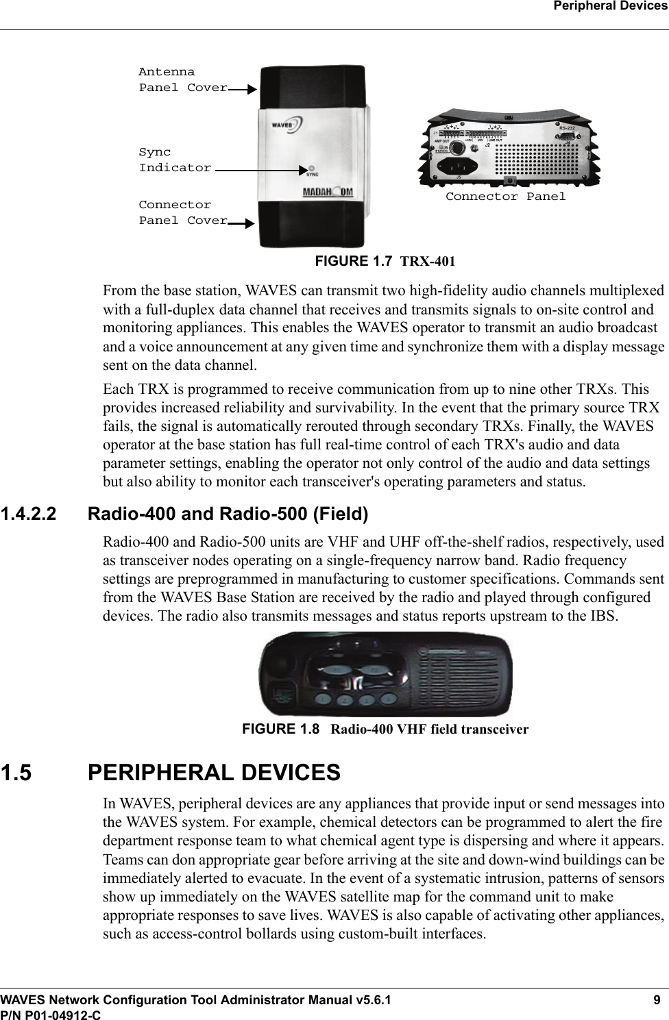
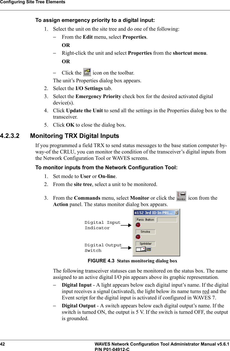
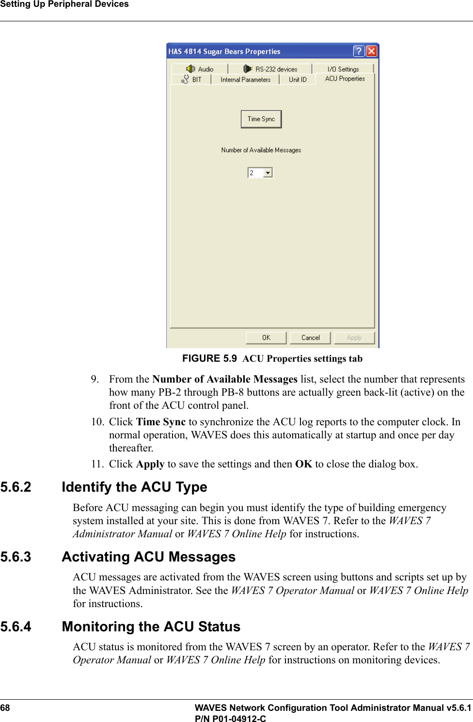
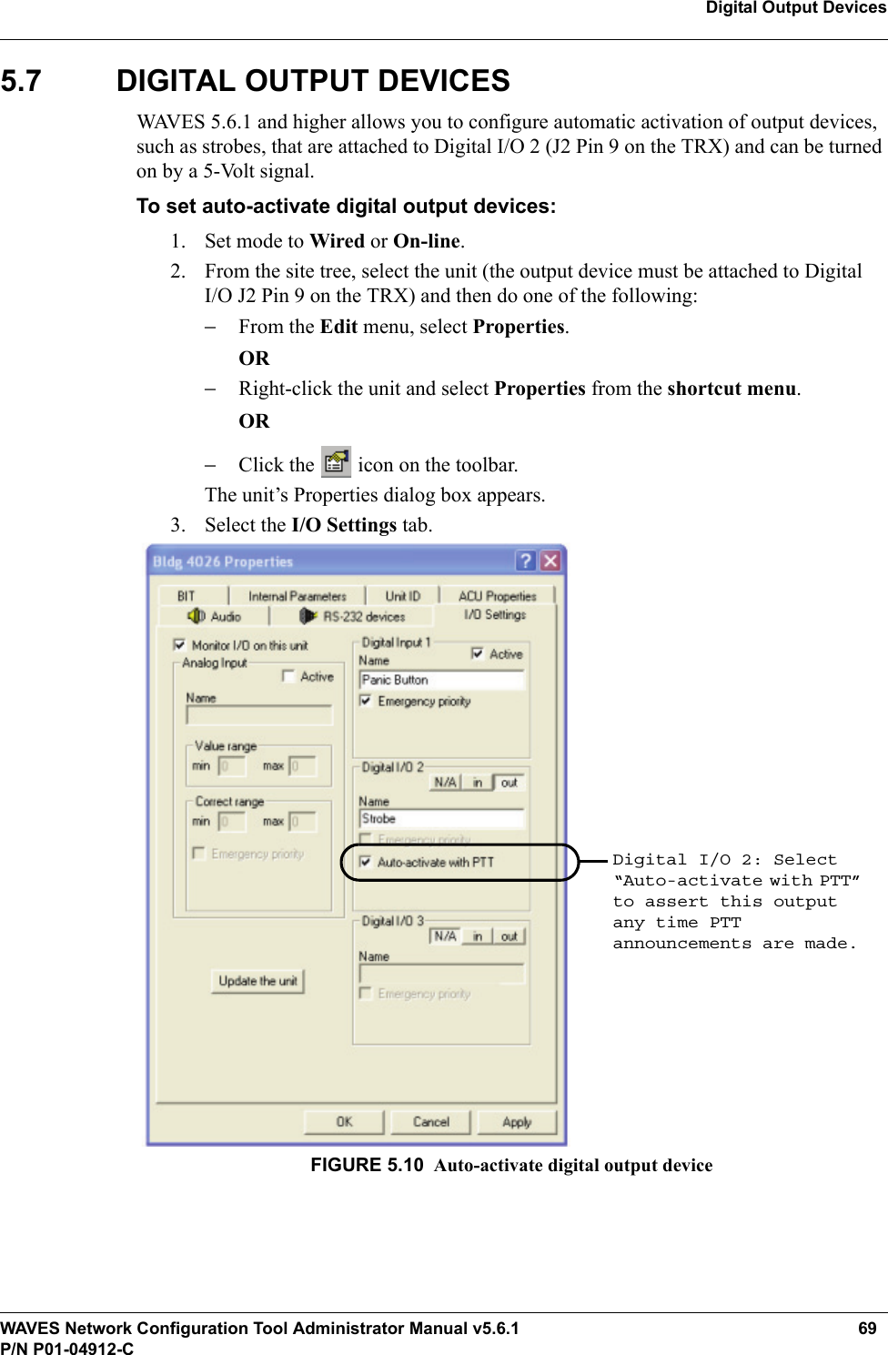
Cooper Notification TRX-401 EMERGENCY NOTIFICATION SYSTEM User Manual WAVES Network Configuration Tool v5 6 1
Cooper Notification, Inc. EMERGENCY NOTIFICATION SYSTEM WAVES Network Configuration Tool v5 6 1
UserManual.wiki
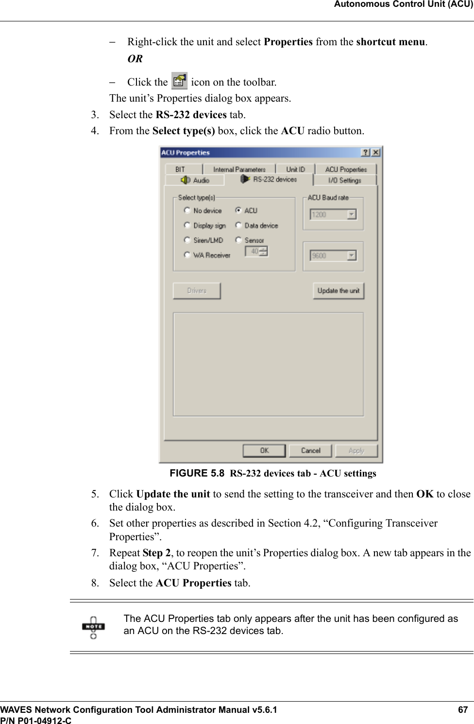
>
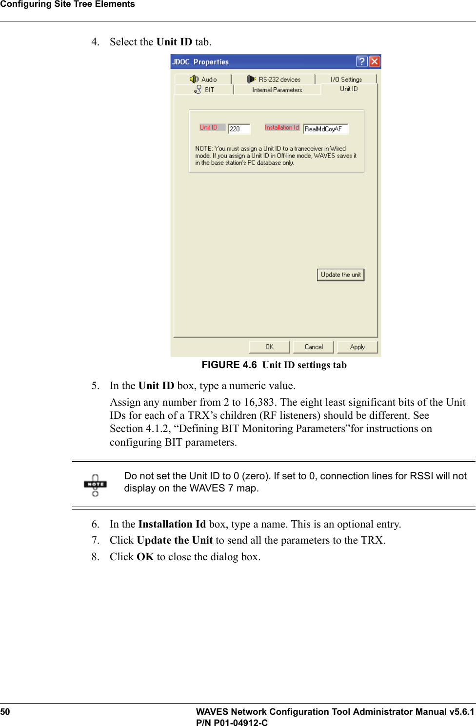
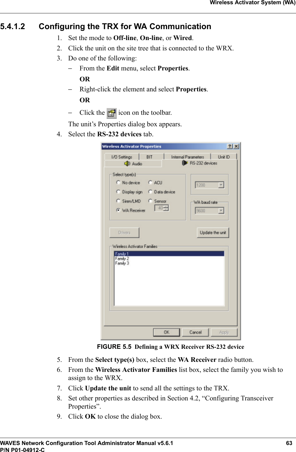
Cooper Notification
>
TRX 401 User Manual
Users Manual
Navigation menu
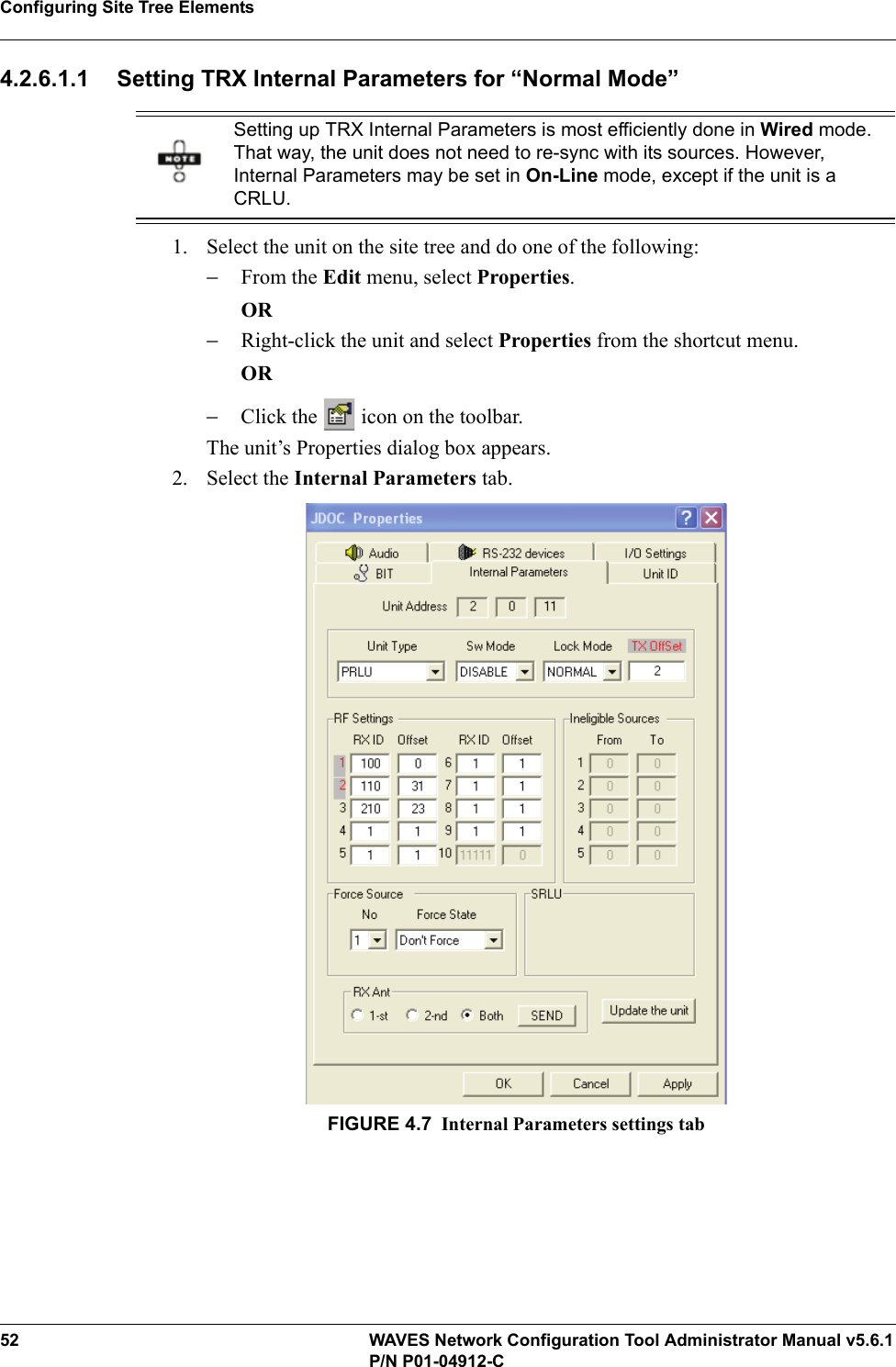
Upload a User Manual
Namespaces
Wiki Guide
HTML
PDF
Info
Views
User Manual
Discussion / Help
Navigation
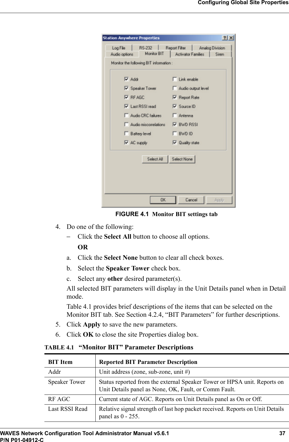
![WAVES Network Configuration Tool Administrator Manual v5.6.1 iP/N P01-04912-CCOPYRIGHTCopyright © 2010, Cooper Notification, Inc. All rights reserved. Cooper Notification and its logo are trademarks of Cooper Notification, Inc.Cooper Notification, Inc., a premier supplier of MNS to the Department of Defense and U.S. government, is part of the Cooper Notification business which also includes Cooper Wheelock, Inc., Roam Secure, Inc., and MEDC.Under the copyright laws, this manual may not be reproduced in any form without the prior written consent of Cooper Notification, Inc. No patent liability is assumed with respect to the use of the information contained herein.Any use of WAVES Software is subject to and conditioned upon [your] acceptance of the Cooper Notification, Inc. software licensing agreement.TRADEMARKSWAVES and the WAVES logo are trademarks of Cooper Notification, Inc. RSAN and RSIX are products of Roam Secure, Inc. dba Cooper Notification protected by U.S. patent 7,409,428; other patents pending. HPSA, SPT, and LMD are trademarks of Cooper Notification, Inc. in the U.S.A. and other countries. Windows is a registered trademark of Microsoft, Inc. Other brands and their products are trademarks or registered trademarks of their respective holders and should be noted as such.EXPORTThis document contains technical data that may be controlled under the U.S. Export Administration Regulations and may be subject to the approval of the U.S. Department of Commerce prior to export. Any export, directly or indirectly, in contravention of the U.S. Export Administration Regulation is prohibited.DISCLAIMERThis manual has been reviewed for accuracy when used in conjunction with Cooper Notification authorized administrator and/or operator training. The information contained herein was accurate for the software at the time of this manual's production. Cooper Notification assumes no liability for damages incurred directly or indirectly from errors, omissions, or discrepancies between WAVES and the manual.](https://usermanual.wiki/Cooper-Notification/TRX-401/User-Guide-1273404-Page-3.png)