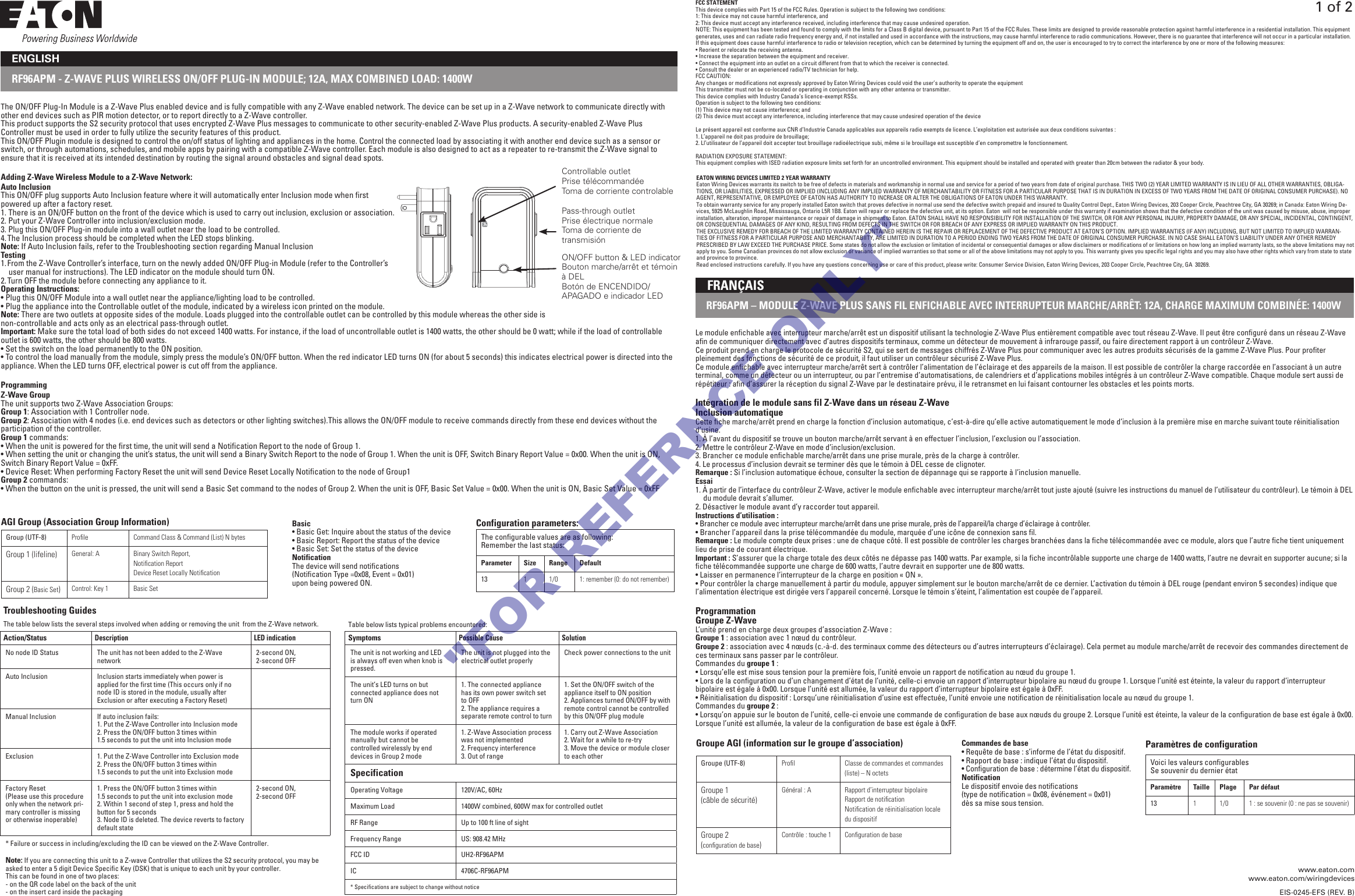
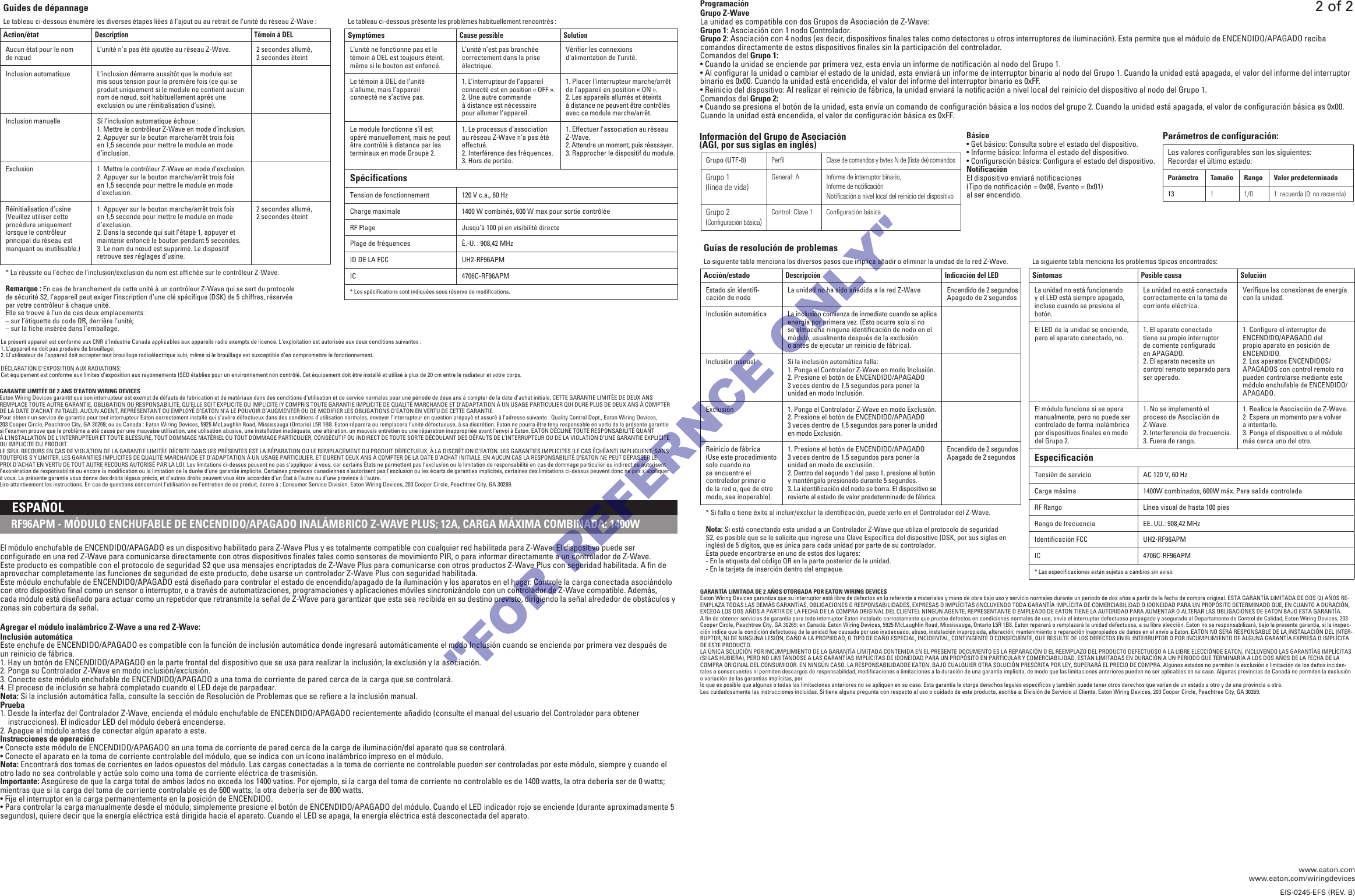
Cooper Wiring Devices RF96APM Z-WAVE PLUS WIRELESS ON/OFF PLUG-IN MODULE User Manual

Cooper Wiring Devices Inc Z-WAVE PLUS WIRELESS ON/OFF PLUG-IN MODULE Users Manual

Users Manual.pdf

RF96APM - Z-WAVE PLUS WIRELESS ON/OFF PLUG-IN MODULE; 12A, MAX COMBINED LOAD: 1400WENGLISHThe ON/OFF Plug-In Module is a Z-Wave Plus enabled device and is fully compatible with any Z-Wave enabled network. The device can be set up in a Z-Wave network to communicate directly with other end devices such as PIR motion detector, or to report directly to a Z-Wave controller.This product supports the S2 security protocol that uses encrypted Z-Wave Plus messages to communicate to other security-enabled Z-Wave Plus products. A security-enabled Z-Wave Plus Controller must be used in order to fully utilize the security features of this product.This ON/OFF Plugin module is designed to control the on/off status of lighting and appliances in the home. Control the connected load by associating it with another end device such as a sensor or switch, or through automations, schedules, and mobile apps by pairing with a compatible Z-Wave controller. Each module is also designed to act as a repeater to re-transmit the Z-Wave signal to ensure that it is received at its intended destination by routing the signal around obstacles and signal dead spots.Adding Z-Wave Wireless Module to a Z-Wave Network:Auto InclusionThis ON/OFF plug supports Auto Inclusion feature where it will automatically enter Inclusion mode when first powered up after a factory reset.1. There is an ON/OFF button on the front of the device which is used to carry out inclusion, exclusion or association.2. Put your Z-Wave Controller into inclusion/exclusion mode.3. Plug this ON/OFF Plug-in module into a wall outlet near the load to be controlled.4. The Inclusion process should be completed when the LED stops blinking.Note: If Auto Inclusion fails, refer to the Troubleshooting section regarding Manual InclusionTesting1. From the Z-Wave Controller’s interface, turn on the newly added ON/OFF Plug-in Module (refer to the Controller’s user manual for instructions). The LED indicator on the module should turn ON.2. Turn OFF the module before connecting any appliance to it. Operating Instructions:• Plug this ON/OFF Module into a wall outlet near the appliance/lighting load to be controlled.• Plug the appliance into the Controllable outlet of the module, indicated by a wireless icon printed on the module.Note: There are two outlets at opposite sides of the module. Loads plugged into the controllable outlet can be controlled by this module whereas the other side is non-controllable and acts only as an electrical pass-through outlet.Important: Make sure the total load of both sides do not exceed 1400 watts. For instance, if the load of uncontrollable outlet is 1400 watts, the other should be 0 watt; while if the load of controllable outlet is 600 watts, the other should be 800 watts. • Set the switch on the load permanently to the ON position.• To control the load manually from the module, simply press the module’s ON/OFF button. When the red indicator LED turns ON (for about 5 seconds) this indicates electrical power is directed into the appliance. When the LED turns OFF, electrical power is cut off from the appliance.ProgrammingZ-Wave GroupThe unit supports two Z-Wave Association Groups:Group 1: Association with 1 Controller node.Group 2: Association with 4 nodes (i.e. end devices such as detectors or other lighting switches).This allows the ON/OFF module to receive commands directly from these end devices without the participation of the controller.Group 1 commands:• When the unit is powered for the first time, the unit will send a Notification Report to the node of Group 1. • When setting the unit or changing the unit’s status, the unit will send a Binary Switch Report to the node of Group 1. When the unit is OFF, Switch Binary Report Value = 0x00. When the unit is ON, Switch Binary Report Value = 0xFF.• Device Reset: When performing Factory Reset the unit will send Device Reset Locally Notification to the node of Group1Group 2 commands:• When the button on the unit is pressed, the unit will send a Basic Set command to the nodes of Group 2. When the unit is OFF, Basic Set Value = 0x00. When the unit is ON, Basic Set Value = 0xFF Controllable outletPrise télécommandéeToma de corriente controlablePass-through outletPrise électrique normale Toma de corriente de  transmisiónConfiguration parameters:The configurable values are as following:Remember the last status:Parameter Size Range Default13 1 1/0 1: remember (0: do not remember)Group (UTF-8) Profile Command Class & Command (List) N bytesGroup 1 (lifeline) General: A Binary Switch Report,Notification ReportDevice Reset Locally NotificationGroup 2 (Basic Set)Control: Key 1 Basic SetAGI Group (Association Group Information) Basic• Basic Get: Inquire about the status of the device• Basic Report: Report the status of the device• Basic Set: Set the status of the deviceNotificationThe device will send notifications (Notification Type =0x08, Event = 0x01) upon being powered ON.FCC STATEMENTThis device complies with Part 15 of the FCC Rules. Operation is subject to the following two conditions:1: This device may not cause harmful interference, and2: This device must accept any interference received, including interference that may cause undesired operation.NOTE: This equipment has been tested and found to comply with the limits for a Class B digital device, pursuant to Part 15 of the FCC Rules. These limits are designed to provide reasonable protection against harmful interference in a residential installation. This equipment generates, uses and can radiate radio frequency energy and, if not installed and used in accordance with the instructions, may cause harmful interference to radio communications. However, there is no guarantee that interference will not occur in a particular installation. If this equipment does cause harmful interference to radio or television reception, which can be determined by turning the equipment off and on, the user is encouraged to try to correct the interference by one or more of the following measures:• Reorient or relocate the receiving antenna.• Increase the separation between the equipment and receiver.• Connect the equipment into an outlet on a circuit different from that to which the receiver is connected.• Consult the dealer or an experienced radio/TV technician for help.FCC CAUTION:Any changes or modifications not expressly approved by Eaton Wiring Devices could void the user’s authority to operate the equipment This transmitter must not be co-located or operating in conjunction with any other antenna or transmitter.This device complies with Industry Canada’s licence-exempt RSSs. Operation is subject to the following two conditions:(1) This device may not cause interference; and(2) This device must accept any interference, including interference that may cause undesired operation of the deviceLe présent appareil est conforme aux CNR d’Industrie Canada applicables aux appareils radio exempts de licence. L’exploitation est autorisée aux deux conditions suivantes :1. L’appareil ne doit pas produire de brouillage;2. Ll’utilisateur de l’appareil doit accepter tout brouillage radioélectrique subi, même si le brouillage est susceptible d’en compromettre le fonctionnement.RADIATION EXPOSURE STATEMENT:This equipment complies with ISED radiation exposure limits set forth for an uncontrolled environment. This equipment should be installed and operated with greater than 20cm between the radiator & your body.ON/OFF button & LED indicatorBouton marche/arrêt et témoin à DELBotón de ENCENDIDO/APAGADO e indicador LEDTroubleshooting GuidesThe table below lists the several steps involved when adding or removing the unit  from the Z-Wave network.Action/StatusDescription LED indicationNo node ID Status The unit has not been added to the Z-Wave network 2-second ON,2-second OFFAuto Inclusion Inclusion starts immediately when power is applied for the first time (This occurs only if no node ID is stored in the module, usually after  Exclusion or after executing a Factory Reset) Manual Inclusion If auto inclusion fails: 1. Put the Z-Wave Controller into Inclusion mode2. Press the ON/OFF button 3 times within1.5 seconds to put the unit into Inclusion modeExclusion 1. Put the Z-Wave Controller into Exclusion mode2. Press the ON/OFF button 3 times within1.5 seconds to put the unit into Exclusion modeFactory Reset(Please use this procedure only when the network pri-mary controller is missing or otherwise inoperable)1. Press the ON/OFF button 3 times within1.5 seconds to put the unit into exclusion mode 2. Within 1 second of step 1, press and hold the button for 5 seconds3. Node ID is deleted. The device reverts to factory default state2-second ON,2-second OFF* Failure or success in including/excluding the ID can be viewed on the Z-Wave Controller.Note: If you are connecting this unit to a Z-wave Controller that utilizes the S2 security protocol, you may be asked to enter a 5 digit Device Specific Key (DSK) that is unique to each unit by your controller.  This can be found in one of two places:- on the QR code label on the back of the unit- on the insert card inside the packagingEATON WIRING DEVICES LIMITED 2 YEAR WARRANTYEaton Wiring Devices warrants its switch to be free of defects in materials and workmanship in normal use and service for a period of two years from date of original purchase. THIS TWO (2) YEAR LIMITED WARRANTY IS IN LIEU OF ALL OTHER WARRANTIES, OBLIGA-TIONS, OR LIABILITIES, EXPRESSED OR IMPLIED (INCLUDING ANY IMPLIED WARRANTY OF MERCHANTABILITY OR FITNESS FOR A PARTICULAR PURPOSE THAT IS IN DURATION IN EXCESS OF TWO YEARS FROM THE DATE OF ORIGINAL CONSUMER PURCHASE). NO AGENT, REPRESENTATIVE, OR EMPLOYEE OF EATON HAS AUTHORITY TO INCREASE OR ALTER THE OBLIGATIONS OF EATON UNDER THIS WARRANTY.To obtain warranty service for any properly installed Eaton switch that proves defective in normal use send the defective switch prepaid and insured to Quality Control Dept., Eaton Wiring Devices, 203 Cooper Circle, Peachtree City, GA 30269; in Canada: Eaton Wiring De-vices, 5925 McLaughlin Road, Mississauga, Ontario L5R 1B8. Eaton will repair or replace the defective unit, at its option. Eaton  will not be responsible under this warranty if examination shows that the defective condition of the unit was caused by misuse, abuse, improper installation, alteration, improper maintenance or repair of damage in shipment to Eaton. EATON SHALL HAVE NO RESPONSIBILITY FOR INSTALLATION OF THE SWITCH, OR FOR ANY PERSONAL INJURY, PROPERTY DAMAGE, OR ANY SPECIAL, INCIDENTAL, CONTINGENT, OR CONSEQUENTIAL DAMAGES OF ANY KIND, RESULTING FROM DEFECTS IN THE SWITCH OR FOR BREACH OF ANY EXPRESS OR IMPLIED WARRANTY ON THIS PRODUCT.THE EXCLUSIVE REMEDY FOR BREACH OF THE LIMITED WARRANTY CONTAINED HEREIN IS THE REPAIR OR REPLACEMENT OF THE DEFECTIVE PRODUCT AT EATON’S OPTION. IMPLIED WARRANTIES (IF ANY) INCLUDING, BUT NOT LIMITED TO IMPLIED WARRAN-TIES OF FITNESS FOR A PARTICULAR PURPOSE AND MERCHANTABIITY, ARE LIMITED IN DURATION TO A PERIOD ENDING TWO YEARS FROM THE DATE OF ORIGINAL CONSUMER PURCHASE. IN NO CASE SHALL EATON’S LIABILITY UNDER ANY OTHER REMEDY PRESCRIBED BY LAW EXCEED THE PURCHASE PRICE. Some states do not allow the exclusion or limitation of incidental or consequential damages or allow disclaimers or modifications of or limitations on how long an implied warranty lasts, so the above limitations may not apply to you. Some Canadian provinces do not allow exclusion or variance of implied warranties so that some or all of the above limitations may not apply to you. This warranty gives you specific legal rights and you may also have other rights which vary from state to state and province to province.Read enclosed instructions carefully. If you have any questions concerning use or care of this product, please write: Consumer Service Division, Eaton Wiring Devices, 203 Cooper Circle, Peachtree City, GA  30269.Table below lists typical problems encountered:SymptomsPossible Cause SolutionThe unit is not working and LED is always off even when knob is pressed.The unit is not plugged into the electrical outlet properly Check power connections to the unitThe unit’s LED turns on but connected appliance does not turn ON1. The connected appliance has its own power switch set to OFF2. The appliance requires a separate remote control to turn1. Set the ON/OFF switch of theappliance itself to ON position2. Appliances turned ON/OFF by with remote control cannot be controlled by this ON/OFF plug moduleThe module works if operated manually but cannot be controlled wirelessly by end  devices in Group 2 mode1. Z-Wave Association process was not implemented2. Frequency interference3. Out of range1. Carry out Z-Wave Association2. Wait for a while to re-try3. Move the device or module closer to each otherSpecificationOperating Voltage 120V/AC, 60HzMaximum Load 1400W combined, 600W max for controlled outletRF Range Up to 100 ft line of sightFrequency Range US: 908.42 MHzFCC ID UH2-RF96APMIC 4706C-RF96APM* Specifications are subject to change without noticewww.eaton.comwww.eaton.com/wiringdevicesEIS-0245-EFS (REV. B)Le module enfichable avec interrupteur marche/arrêt est un dispositif utilisant la technologie Z-Wave Plus entièrement compatible avec tout réseau Z-Wave. Il peut être configuré dans un réseau Z-Wave afin decommuniquer directement avec d’autres dispositifs terminaux, comme un détecteur de mouvement à infrarouge passif, ou faire directement rapport à un contrôleur Z-Wave.Ce produit prend en charge le protocole de sécuritéS2, qui se sert de messages chiffrés Z-Wave Plus pour communiquer avec les autres produits sécurisés de la gamme Z-Wave Plus. Pour profiter pleinement des fonctions de sécurité de ce produit, il faut utiliser un contrôleur sécurisé Z-Wave Plus.Ce module enfichable avec interrupteur marche/arrêt sert à contrôler l’alimentation de l’éclairage et des appareils de la maison. Il est possible de contrôler la charge raccordée en l’associant à un autre terminal, comme un détecteur ou un interrupteur, ou par l’entremise d’automatisations, de calendriers et d’applications mobiles intégrés à un contrôleur Z-Wave compatible. Chaque module sert aussi de répétiteur: afin d’assurer la réception du signal Z-Wave par le destinataire prévu, il le retransmet en lui faisant contourner les obstacles et les points morts.Intégration de le module sans fil Z-Wave dans un réseau Z-WaveInclusion automatiqueCette fiche marche/arrêt prend en charge la fonction d’inclusion automatique, c’est-à-dire qu’elle active automatiquement le mode d’inclusion à la première mise en marche suivant toute réinitialisation d’usine.1. À l’avant du dispositif se trouve un bouton marche/arrêt servant à en effectuer l’inclusion, l’exclusion ou l’association.2. Mettre le contrôleur Z-Wave en mode d’inclusion/exclusion.3. Brancher ce module enfichable marche/arrêt dans une prise murale, près de la charge à contrôler.4. Le processus d’inclusion devrait se terminer dès que le témoin à DEL cesse de clignoter.Remarque: Si l’inclusion automatique échoue, consulter la section de dépannage qui se rapporte à l’inclusion manuelle.Essai1. À partir de l’interface du contrôleur Z-Wave, activer le module enfichable avec interrupteur marche/arrêt tout juste ajouté (suivre les instructions du manuel de l’utilisateur du contrôleur). Le témoin à DEL du module devrait s’allumer.2. Désactiver le module avant d’y raccorder tout appareil. Instructions d’utilisation:• Brancher ce module avec interrupteur marche/arrêt dans une prise murale, près de l’appareil/la charge d’éclairage à contrôler.• Brancher l’appareil dans la prise télécommandée du module, marquée d’une icône de connexion sans fil.Remarque: Le module compte deux prises: une de chaque côté. Il est possible de contrôler les charges branchées dans la fiche télécommandée avec ce module, alors que l’autre fiche tient uniquement lieu de prise de courant électrique.Important: S’assurer que la charge totale des deux côtés ne dépasse pas 1400watts. Par example, si la fiche incontrôlable supporte une charge de 1400 watts, l’autre ne devrait en supporter aucune; si la fiche télécommandée supporte une charge de 600 watts, l’autre devrait en supporter une de 800 watts. • Laisser en permanence l’interrupteur de la charge en position «ON».• Pour contrôler la charge manuellement à partir du module, appuyer simplement sur le bouton marche/arrêt de ce dernier. L’activation du témoin à DEL rouge (pendant environ 5secondes) indique que l’alimentation électrique est dirigée vers l’appareil concerné. Lorsque le témoin s’éteint, l’alimentation est coupée de l’appareil.ProgrammationGroupe Z-WaveL’unité prend en charge deux groupes d’association Z-Wave:Groupe1: association avec 1nœud du contrôleur.Groupe2: association avec 4nœuds (c.-à-d. des terminaux comme des détecteurs ou d’autres interrupteurs d’éclairage). Cela permet au module marche/arrêt de recevoir des commandes directement de ces terminaux sans passer par le contrôleur.Commandes du groupe1:• Lorsqu’elle est mise sous tension pour la première fois, l’unité envoie un rapport de notification au nœud du groupe1. • Lors de la configuration ou d’un changement d’état de l’unité, celle-ci envoie un rapport d’interrupteur bipolaire au nœud du groupe1. Lorsque l’unité est éteinte, la valeur du rapport d’interrupteur bipolaire est égale à 0x00. Lorsque l’unité est allumée, la valeur du rapport d’interrupteur bipolaire est égale à 0xFF.• Réinitialisation du dispositif: Lorsqu’une réinitialisation d’usine est effectuée, l’unité envoie une notification de réinitialisation locale au nœud du groupe1.Commandes du groupe2:•Lorsqu’on appuie sur le bouton de l’unité, celle-ci envoie une commande de configuration de base aux nœuds du groupe2. Lorsque l’unité est éteinte, la valeur de la configuration de base est égale à 0x00. Lorsque l’unité est allumée, la valeur de la configuration de base est égale à 0xFF. RF96APM–MODULE Z-WAVE PLUS SANS FIL ENFICHABLE AVEC INTERRUPTEUR MARCHE/ARRÊT: 12A, CHARGE MAXIMUM COMBINÉE: 1400W    FRANÇAISParamètres de configurationVoici les valeurs configurablesSe souvenir du dernier étatParamètre Taille Plage Par défaut13 1 1/0 1: se souvenir (0: ne pas sesouvenir)Groupe (UTF-8) Profil Classe de commandes et commandes (liste)– NoctetsGroupe1 (câbledesécurité)Général: A Rapport d’interrupteur bipolaireRapport de notificationNotification de réinitialisation locale du dispositifGroupe2 (configurationdebase)Contrôle: touche1 Configuration de baseGroupe AGI (information sur le groupe d’association) Commandes de base•Requête de base: s’informe de l’état du dispositif.•Rapport de base: indique l’état du dispositif.•Configuration de base: détermine l’état du dispositif.NotificationLe dispositif envoie des notifications (type de notification=0x08, événement=0x01) dès sa mise sous tension.1 of 2"FOR REFERNCE ONLY"
Le présent appareil est conforme aux CNR d’Industrie Canada applicables aux appareils radio exempts de licence. L’exploitation est autorisée aux deux conditions suivantes :1. L’appareil ne doit pas produire de brouillage;2. Ll’utilisateur de l’appareil doit accepter tout brouillage radioélectrique subi, même si le brouillage est susceptible d’en compromettre le fonctionnement.DÉCLARATION D’EXPOSITION AUX RADIATIONS:Cet équipement est conforme aux limites d’exposition aux rayonnements ISED établies pour un environnement non contrôlé. Cet équipement doit être installé et utilisé à plus de 20 cm entre le radiateur et votre corps.GARANTIE LIMITÉE DE 2ANS D’EATONWIRINGDEVICESEatonWiringDevices garantit que son interrupteur est exempt de défauts de fabrication et de matériaux dans des conditions d’utilisation et de service normales pour une période de deux ans à compter de la date d’achat initiale. CETTE GARANTIE LIMITÉE DE DEUX ANS REMPLACE TOUTE AUTRE GARANTIE, OBLIGATION OU RESPONSABILITÉ, QU’ELLE SOIT EXPLICITE OU IMPLICITE (Y COMPRIS TOUTE GARANTIE IMPLICITE DE QUALITÉ MARCHANDE ET D’ADAPTATION À UN USAGE PARTICULIER QUI DURE PLUS DE DEUX ANS À COMPTER DELA DATE D’ACHAT INITIALE). AUCUN AGENT, REPRÉSENTANT OU EMPLOYÉ D’EATON N’A LE POUVOIR D’AUGMENTER OU DE MODIFIER LES OBLIGATIONS D’EATON EN VERTU DE CETTE GARANTIE.Pour obtenir un service de garantie pour tout interrupteur Eaton correctement installé qui s’avère défectueux dans des conditions d’utilisation normales, envoyer l’interrupteur en question prépayé et assuré à l’adresse suivante: Quality Control Dept., EatonWiringDevices, 203CooperCircle, PeachtreeCity, GA30269; ou au Canada: EatonWiringDevices, 5925McLaughlinRoad, Mississauga (Ontario) L5R1B8. Eaton réparera ou remplacera l’unité défectueuse, à sa discrétion. Eaton ne pourra être tenu responsable en vertu de la présente garantie si l’examen prouve que le problème a été causé par une mauvaise utilisation, une utilisation abusive, une installation inadéquate, une altération, un mauvais entretien ou une réparation inappropriée avant l’envoi à Eaton. EATON DÉCLINE TOUTE RESPONSABILITÉ QUANT ÀL’INSTALLATION DE L’INTERRUPTEUR ET TOUTE BLESSURE, TOUT DOMMAGE MATÉRIEL OU TOUT DOMMAGE PARTICULIER, CONSÉCUTIF OU INDIRECT DE TOUTE SORTE DÉCOULANT DES DÉFAUTS DE L’INTERRUPTEUR OU DE LA VIOLATION D’UNE GARANTIE EXPLICITE OU IMPLICITE DU PRODUIT.LE SEUL RECOURS EN CAS DE VIOLATION DE LA GARANTIE LIMITÉE DÉCRITE DANS LES PRÉSENTES EST LA RÉPARATION OU LE REMPLACEMENT DU PRODUIT DÉFECTUEUX, À LA DISCRÉTION D’EATON. LES GARANTIES IMPLICITES (LE CAS ÉCHÉANT) IMPLIQUENT, SANS TOUTEFOIS S’Y LIMITER, LES GARANTIES IMPLICITES DE QUALITÉ MARCHANDE ET D’ADAPTATION À UN USAGE PARTICULIER, ET DURENT DEUX ANS À COMPTER DE LA DATE D’ACHAT INITIALE. EN AUCUN CAS LA RESPONSABILITÉ D’EATON NE PEUT DÉPASSER LE PRIX D’ACHAT EN VERTU DE TOUT AUTRE RECOURS AUTORISÉ PAR LA LOI. Les limitations ci-dessus peuvent ne pas s’appliquer à vous, car certains États ne permettent pas l’exclusion ou la limitation de responsabilité en cas de dommage particulier ou indirect ou autorisent l’exonération de responsabilité ou encore la modification ou la limitation de la durée d’une garantie implicite. Certaines provinces canadiennes n’autorisent pas l’exclusion ou les écarts de garanties implicites, certaines des limitations ci-dessus peuvent donc ne pas s’appliquer àvous. La présente garantie vous donne des droits légaux précis, et d’autres droits peuvent vous être accordés d’un État à l’autre ou d’une province à l’autre.Lire attentivement les instructions. En cas de questions concernant l’utilisation ou l’entretien de ce produit, écrire à: ConsumerServiceDivision, EatonWiringDevices, 203Cooper Circle, PeachtreeCity, GA30269.Guides de dépannageLe tableau ci-dessous énumère les diverses étapes liées à l’ajout ou au retrait de l’unité du réseau Z-Wave :Action/étatDescription Témoin à DELAucun état pour le nom de nœud L’unité n’a pas été ajoutée au réseau Z-Wave. 2secondes allumé, 2secondes éteintInclusion automatique L’inclusion démarre aussitôt que le module est mis sous tension pour la première fois (ce qui se produit uniquement si le module ne contient aucun nom de nœud, soit habituellement après une exclusion ou une réinitialisation d’usine). Inclusion manuelle Si l’inclusion automatique échoue:1. Mettre le contrôleur Z-Wave en mode d’inclusion.2. Appuyer sur le bouton marche/arrêt trois fois en 1,5seconde pour mettre le module en mode d’inclusion.Exclusion 1. Mettre le contrôleur Z-Wave en mode d’exclusion.2. Appuyer sur le bouton marche/arrêt trois fois en 1,5seconde pour mettre le module en mode d’exclusion.Réinitialisation d’usine (Veuillez utiliser cette procédure uniquement lorsque le contrôleur principal du réseau est manquant ou inutilisable.)1. Appuyer sur le bouton marche/arrêt trois fois en 1,5seconde pour mettre le module en mode d’exclusion. 2. Dans la seconde qui suit l’étape1, appuyer et maintenir enfoncé le bouton pendant 5secondes.3. Le nom du nœud est supprimé. Le dispositif retrouve ses réglages d’usine.2secondes allumé, 2secondes éteint*La réussite ou l’échec de l’inclusion/exclusion du nom est affichée sur le contrôleur Z-Wave.Remarque: En cas de branchement de cette unité à un contrôleur Z-Wave qui se sert du protocole desécuritéS2, l’appareil peut exiger l’inscription d’une clé spécifique (DSK) de 5chiffres, réservée parvotrecontrôleur à chaque unité. Elle se trouve à l’un de ces deux emplacements:– sur l’étiquette du codeQR, derrière l’unité;– sur la fiche insérée dans l’emballage.Le tableau ci-dessous présente les problèmes habituellement rencontrés:SymptômesCause possible SolutionL’unité ne fonctionne pas et le témoin à DEL est toujours éteint, même si le bouton est enfoncé.L’unité n’est pas branchée correctement dans la prise électrique.Vérifier les connexions d’alimentation de l’unité.Le témoin à DEL de l’unité s’allume, mais l’appareil connecténe s’active pas.1. L’interrupteur de l’appareil connecté est en position «OFF».2. Une autre commande àdistance est nécessaire pourallumer l’appareil.1. Placer l’interrupteur marche/arrêt de l’appareil en position «ON».2. Les appareils allumés et éteints àdistance ne peuvent être contrôlés avec ce module marche/arrêt.Le module fonctionne s’il est opéré manuellement, mais ne peut être contrôlé à distance par les terminaux en mode Groupe2.1. Le processus d’association au réseau Z-Wave n’a pas été effectué.2. Interférence des fréquences.3. Hors de portée.1. Effectuer l’association au réseau Z-Wave.2. Attendre un moment, puis réessayer.3. Rapprocher le dispositif du module.SpécificationsTension de fonctionnement 120V c.a., 60HzCharge maximale 1400 W combinés, 600 W max pour sortie contrôléeRF Plage Jusqu’à 100 pi en visibilité directePlage de fréquences É.-U.: 908,42MHzID DE LA FCC UH2-RF96APMIC 4706C-RF96APM*Les spécifications sont indiquées sous réserve de modifications.  RF96APM - MÓDULO ENCHUFABLE DE ENCENDIDO/APAGADO INALÁMBRICO Z-WAVE PLUS; 12A, CARGA MÁXIMA COMBINADA: 1400W     ESPAÑOLEl módulo enchufable de ENCENDIDO/APAGADO es un dispositivo habilitado para Z-Wave Plus y es totalmente compatible con cualquier red habilitada para Z-Wave. El dispositivo puede ser configurado en una red Z-Wave para comunicarse directamente con otros dispositivos finales tales como sensores de movimiento PIR, o para informar directamente a un controlador de Z-Wave.Este producto es compatible con el protocolo de seguridad S2 que usa mensajes encriptados de Z-Wave Plus para comunicarse con otros productos Z-Wave Plus con seguridad habilitada. A fin de aprovechar completamente las funciones de seguridad de este producto, debe usarse un controlador Z-Wave Plus con seguridad habilitada.Este módulo enchufable de ENCENDIDO/APAGADO está diseñado para controlar el estado de encendido/apagado de la iluminación y los aparatos en el hogar. Controle la carga conectada asociándolo con otro dispositivo final como un sensor o interruptor, o a través de automatizaciones, programaciones y aplicaciones móviles sincronizándolo con un controlador de Z-Wave compatible. Además, cada módulo está diseñado para actuar como un repetidor que retransmite la señal de Z-Wave para garantizar que esta sea recibida en su destino previsto, dirigiendo la señal alrededor de obstáculos y zonas sin cobertura de señal.Agregar el módulo inalámbrico Z-Wave a una red Z-Wave:Inclusión automáticaEste enchufe de ENCENDIDO/APAGADO es compatible con la función de inclusión automática donde ingresará automáticamente el modo Inclusión cuando se encienda por primera vez después de un reinicio de fábrica.1. Hay un botón de ENCENDIDO/APAGADO en la parte frontal del dispositivo que se usa para realizar la inclusión, la exclusión y la asociación.2. Ponga su Controlador Z-Wave en modo inclusión/exclusión.3. Conecte este módulo enchufable de ENCENDIDO/APAGADO a una toma de corriente de pared cerca de la carga que se controlará.4. El proceso de inclusión se habrá completado cuando el LED deje de parpadear.Nota: Si la inclusión automática falla, consulte la sección de Resolución de Problemas que se refiere a la inclusión manual.Prueba1. Desde la interfaz del Controlador Z-Wave, encienda el módulo enchufable de ENCENDIDO/APAGADO recientemente añadido (consulte el manual del usuario del Controlador para obtener instrucciones). El indicador LED del módulo deberá encenderse.2. Apague el módulo antes de conectar algún aparato a este. Instrucciones de operación• Conecte este módulo de ENCENDIDO/APAGADO en una toma de corriente de pared cerca de la carga de iluminación/del aparato que se controlará.• Conecte el aparato en la toma de corriente controlable del módulo, que se indica con un ícono inalámbrico impreso en el módulo.Nota: Encontrará dos tomas de corrientes en lados opuestos del módulo. Las cargas conectadas a la toma de corriente no controlable pueden ser controladas por este módulo, siempre y cuando el otro lado no sea controlable y actúe solo como una toma de corriente eléctrica de trasmisión.Importante: Asegúrese de que la carga total de ambos lados no exceda los 1400 vatios. Por ejemplo, si la carga del toma de corriente no controlable es de 1400 watts, la otra debería ser de 0 watts; mientras que si la carga del toma de corriente controlable es de 600 watts, la otra debería ser de 800 watts. • Fije el interruptor en la carga permanentemente en la posición de ENCENDIDO.• Para controlar la carga manualmente desde el módulo, simplemente presione el botón de ENCENDIDO/APAGADO del módulo. Cuando el LED indicador rojo se enciende (durante aproximadamente 5 segundos), quiere decir que la energía eléctrica está dirigida hacia el aparato. Cuando el LED se apaga, la energía eléctrica está desconectada del aparato.Grupo (UTF-8) Perfil Clase de comandos y bytes N de (lista de) comandosGrupo 1  (línea de vida) General: A Informe de interruptor binario,Informe de notificaciónNotificación a nivel local del reinicio del dispositivoGrupo 2  (Configuración básica)Control: Clave 1 Configuración básicaParámetros de configuración:Los valores configurables son los siguientes:Recordar el último estado:Parámetro Tamaño Rango Valor predeterminado13 1 1/0 1: recuerda (0: no recuerda)Información del Grupo de Asociación  (AGI, por sus siglas en inglés) Básico•  Get básico: Consulta sobre el estado del dispositivo.• Informe básico: Informa el estado del dispositivo.• Configuración básica: Configura el estado del dispositivo.NotificaciónEl dispositivo enviará notificaciones  (Tipo de notificación = 0x08, Evento = 0x01) al ser encendido.Guías de resolución de problemasLa siguiente tabla menciona los diversos pasos que implica añadir o eliminar la unidad de la red Z-Wave.Acción/estadoDescripción Indicación del LEDEstado sin identifi-cación de nodo La unidad no ha sido añadida a la red Z-Wave Encendido de 2 segundos Apagado de 2 segundosInclusión automática La inclusión comienza de inmediato cuando se aplicaenergía por primera vez. (Esto ocurre solo si no se almacena ninguna identificación de nodo en el módulo, usualmente después de la exclusión  o antes de ejecutar un reinicio de fábrica). Inclusión manual Si la inclusión automática falla:1. Ponga el Controlador Z-Wave en modo Inclusión.2. Presione el botón de ENCENDIDO/APAGADO 3veces dentro de 1,5 segundos para poner la unidad en modo Inclusión.Exclusión 1. Ponga el Controlador Z-Wave en modo Exclusión.2. Presione el botón de ENCENDIDO/APAGADO 3veces dentro de 1,5 segundos para poner la unidad en modo Exclusión.Reinicio de fábrica(Use este procedimiento solo cuando no se encuentre el controlador primario de la red o, que de otro modo, sea inoperable).1. Presione el botón de ENCENDIDO/APAGADO 3veces dentro de 1,5 segundos para poner la  unidad en modo de exclusión. 2. Dentro del segundo 1 del paso 1, presione el botón ymanténgalo presionado durante 5 segundos.3. La identificación del nodo se borra. El dispositivo se revierte al estado de valor predeterminado de fábrica.Encendido de 2 segundos Apagado de 2 segundos* Si falla o tiene éxito al incluir/excluir la identificación, puede verlo en el Controlador del Z-Wave.Nota: Si está conectando esta unidad a un Controlador Z-Wave que utiliza el protocolo de seguridad S2, es posible que se le solicite que ingrese una Clave Específica del dispositivo (DSK, por sus siglas en inglés) de 5dígitos, que es única para cada unidad por parte de su controlador.  Esta puede encontrarse en uno de estos dos lugares:- En la etiqueta del código QR en la parte posterior de la unidad.- En la tarjeta de inserción dentro del empaque.La siguiente tabla menciona los problemas típicos encontrados:SíntomasPosible causa SoluciónLa unidad no está funcionando y el LED está siempre apagado, incluso cuando se presiona el botón.La unidad no está conectada correctamente en la toma de corriente eléctrica.Verifique las conexiones de energía con la unidad.El LED de la unidad se enciende, pero el aparato conectado, no. 1. El aparato conectado tiene su propio interruptor de corriente configurado enAPAGADO.2. El aparato necesita un control remoto separado para ser operado.1. Configure el interruptor de  ENCENDIDO/APAGADO del propio aparato en posición de ENCENDIDO.2. Los aparatos ENCENDIDOS/APAGADOS con control remoto no pueden controlarse mediante este módulo enchufable de ENCENDIDO/APAGADO.El módulo funciona si se opera manualmente, pero no puede ser controlado de forma inalámbrica por dispositivos finales en modo del Grupo 2.1. No se implementó el proceso de Asociación de Z-Wave.2. Interferencia de frecuencia.3. Fuera de rango.1. Realice la Asociación de Z-Wave.2. Espere un momento para volver a intentarlo.3. Ponga el dispositivo o el módulo más cerca uno del otro.EspecificaciónTensión de servicio AC 120 V, 60 HzCarga máxima 1400W combinados, 600W máx. Para salida controladaRF Rango Línea visual de hasta 100 piesRango de frecuencia EE.UU.: 908,42 MHzIdentificación FCC UH2-RF96APMIC 4706C-RF96APM* Las especificaciones están sujetas a cambios sin aviso.GARANTÍA LIMITADA DE 2 AÑOS OTORGADA POR EATON WIRING DEVICESEaton Wiring Devices garantiza que su interruptor está libre de defectos en lo referente a materiales y mano de obra bajo uso y servicio normales durante un periodo de dos años a partir de la fecha de compra original. ESTA GARANTÍA LIMITADA DE DOS (2) AÑOS RE-EMPLAZA TODAS LAS DEMÁS GARANTÍAS, OBLIGACIONES O RESPONSABILIDADES, EXPRESAS O IMPLÍCITAS (INCLUYENDO TODA GARANTÍA IMPLÍCITA DE COMERCIABILIDAD O IDONEIDAD PARA UN PROPÓSITO DETERMINADO QUE, EN CUANTO A DURACIÓN, EXCEDA LOS DOS AÑOS A PARTIR DE LA FECHA DE LA COMPRA ORIGINAL DEL CLIENTE). NINGÚN AGENTE, REPRESENTANTE O EMPLEADO DE EATON TIENE LA AUTORIDAD PARA AUMENTAR O ALTERAR LAS OBLIGACIONES DE EATON BAJO ESTA GARANTÍA.A fin de obtener servicios de garantía para todo interruptor Eaton instalado correctamente que pruebe defectos en condiciones normales de uso, envíe el interruptor defectuoso prepagado y asegurado al Departamento de Control de Calidad, Eaton Wiring Devices, 203 Cooper Circle, Peachtree City, GA 30269; en Canadá: Eaton Wiring Devices, 5925 McLaughlin Road, Mississauga, Ontario L5R 1B8. Eaton reparará o remplazará la unidad defectuosa, a su libre elección. Eaton no se responsabilizará, bajo la presente garantía, si la inspec-ción indica que la condición defectuosa de la unidad fue causada por uso inadecuado, abuso, instalación inapropiada, alteración, mantenimiento o reparación inapropiados de daños en el envío a Eaton. EATON NO SERÁ RESPONSABLE DE LA INSTALACIÓN DEL INTER-RUPTOR, NI DE NINGUNA LESIÓN, DAÑO A LA PROPIEDAD, O TIPO DE DAÑO ESPECIAL, INCIDENTAL, CONTINGENTE O CONSECUENTE, QUE RESULTE DE LOS DEFECTOS EN EL INTERRUPTOR O POR INCUMPLIMIENTO DE ALGUNA GARANTÍA EXPRESA O IMPLÍCITA DE ESTE PRODUCTO.LA ÚNICA SOLUCIÓN POR INCUMPLIMIENTO DE LA GARANTÍA LIMITADA CONTENIDA EN EL PRESENTE DOCUMENTO ES LA REPARACIÓN O EL REEMPLAZO DEL PRODUCTO DEFECTUOSO A LA LIBRE ELECCIÓNDE EATON. INCLUYENDO LAS GARANTÍAS IMPLÍCITAS (SI LAS HUBIERA), PERO NO LIMITÁNDOSE A LAS GARANTÍAS IMPLÍCITAS DE IDONEIDAD PARA UN PROPÓSITO EN PARTICULAR Y COMERCIABILIDAD, ESTÁN LIMITADAS EN DURACIÓN A UN PERIODO QUE TERMINARÍA A LOS DOS AÑOS DE LA FECHA DE LA COMPRA ORIGINAL DEL CONSUMIDOR. EN NINGÚN CASO, LA RESPONSABILIDADDE EATON, BAJO CUALQUIER OTRA SOLUCIÓN PRESCRITA POR LEY, SUPERARÁ EL PRECIO DE COMPRA. Algunos estados no permiten la exclusión o limitación de los daños inciden-tales o consecuentes ni permiten descargos de responsabilidad, modificaciones o limitaciones a la duración de una garantía implícita, de modo que las limitaciones anteriores pueden no ser aplicables en su caso. Algunas provincias de Canadá no permiten la exclusión o variación de las garantías implícitas, por  lo que es posible que algunas o todas las limitaciones anteriores no se apliquen en su caso. Esta garantía le otorga derechos legales específicos y también puede tener otros derechos que varían de un estado a otro y de una provincia a otra.Lea cuidadosamente las instrucciones incluidas. Si tiene alguna pregunta con respecto al uso o cuidado de este producto, escriba a: División de Servicio al Cliente, Eaton Wiring Devices, 203 Cooper Circle, Peachtree City, GA 30269.ProgramaciónGrupo Z-WaveLa unidad es compatible con dos Grupos de Asociación de Z-Wave:Grupo 1: Asociación con 1 nodo Controlador.Grupo 2: Asociación con 4 nodos (es decir, dispositivos finales tales como detectores u otros interruptores de iluminación). Esta permite que el módulo de ENCENDIDO/APAGADO reciba comandos directamente de estos dispositivos finales sin la participación del controlador.Comandos del Grupo 1:• Cuando la unidad se enciende por primera vez, esta envía un informe de notificación al nodo del Grupo 1. • Al configurar la unidad o cambiar el estado de la unidad, esta enviará un informe de interruptor binario al nodo del Grupo 1. Cuando la unidad está apagada, el valor del informe del interruptor binario es 0x00. Cuando la unidad está encendida, el valor del informe del interruptor binario es 0xFF.• Reinicio del dispositivo: Al realizar el reinicio de fábrica, la unidad enviará la notificación a nivel local del reinicio del dispositivo al nodo del Grupo 1.Comandos del Grupo 2:• Cuando se presiona el botón de la unidad, esta envía un comando de configuración básica a los nodos del grupo 2. Cuando la unidad está apagada, el valor de configuración básica es 0x00. Cuando la unidad está encendida, el valor de configuración básica es 0xFF. www.eaton.comwww.eaton.com/wiringdevicesEIS-0245-EFS (REV. B)2 of 2"FOR REFERNCE ONLY"

Navigation menu