Coretronic PBP2 Interactive Pen User Manual DDP2000 User Guide
Coretronic Corp. Interactive Pen DDP2000 User Guide
User Manual

DLP® Products for Optoma
Interactive Pen -- AirDraw II
Interactive Module -- PBM
User's Guide
Product Specification
Preliminary
TI Confidential - NDA Restrictions
Interactive Pen and Interactive Module user manual

PointBlank Product Specification, Rev A
Contents
CONTENTS .................................................................................................................................... IV
TABLES .......................................................................................................................................... V
FIGURES......................................................................................................................................... V
1 SCOPE ..................................................................................................................................... 1
2 APPLICABLE DOCUMENTS .................................................................................................. 1
3 OVERVIEW .............................................................................................................................. 2
4 DETAILED DESCRIPTION...................................................................................................... 3
4.1 POINTBLANK HARDWARE..................................................................................................... 3
4.1.1 PointBlank FPGA....................................................................................................... 5
4.1.2 PointBlank Radio Transceiver .(PBM)........................................................................ 5
4.1.3 PointBlank Pointing Device .(AirDraw II).......................................................................... 5
4.2 POINTBLANK WIRELESS....................................................................................................... 6
4.3 POINTBLANK SOFTWARE ..................................................................................................... 6
4.4 OPERATING CONDITIONS ..................................................................................................... 7
TI Confidential – NDA Restrictions IV

PointBlank Product Specification, Rev A
Tables
TABLE 1 POINTBLANK OPERATING CONDITIONS ................................................................... 7
Figures
FIGURE 1 POINTBLANK SYSTEM DIAGRAM ............................................................................. 2
FIGURE 2 POINTBLANK DDP2431 ELECTRONICS DIAGRAM.................................................. 3
FIGURE 3 POINTBLANK DDP2230 ELECTRONICS DIAGRAM.................................................. 4
TI Confidential – NDA Restrictions V
Federal Communication Commission Interference Statement
This equipment has been tested and found to comply with the limits for
a Class B digital device, pursuant to Part 15 of the FCC Rules. These
limits are designed to provide reasonable protection against harmful
interference in a residential installation. This equipment generates,
uses and can radiate radio frequency energy and, if not installed and
used in accordance with the instructions, may cause harmful
interference to radio communications. However, there is no guarantee
that interference will not occur in a particular installation. If this
equipment does cause harmful interference to radio or television
reception, which can be determined by turning the equipment off and
on, the user is encouraged to try to correct the interference by one of
the following measures:
- Reorient or relocate the receiving antenna.
- Increase the separation between the equipment and receiver.
- Connect the equipment into an outlet on a circuit different from that
to which the receiver is connected.
- Consult the dealer or an experienced radio/TV technician for help.
FCC Caution: Any changes or modifications not expressly approved by
the party responsible for compliance could void the user's authority to
operate this equipment.
This device complies with Part 15 of the FCC Rules. Operation is
subject to the following two conditions: (1) This device may not cause
harmful interference, and (2) this device must accept any interference
received, including interference that may cause undesired operation.
Industry Canada Statement
This device complies with RSS-210 of the Industry Canada Rules. Operation
is subject to the following two conditions:
1) this device may not cause interference and
2) this device must accept any interference, including interference that may
cause undesired operation of the device
IMPORTANT NOTE:
IC Radiation Exposure Statement:
This equipment complies with IC radiation exposure limits set forth for an
uncontrolled environment. This equipment should be installed and operated
with minimum distance 20cm between the radiator & your body.
i
NCC :
FORPBM
ID
FORAirDraw II
PointBlank Product Specification, Rev A
1 Scope
This document specifies the functional and performance parameters of the PointBlank enabled
DLP® component set. PointBlank is supported on DDP2230 and DDP243x platforms by adding
additional hardware and software components to the reference design. These additions are
defined in this document.
2 Applicable Documents
• DDP2230 Reference Design Documentation
• DDP2431 Reference Design Documentation
TI Confidential – NDA Restrictions 1
PointBlank Product Specification, Rev A
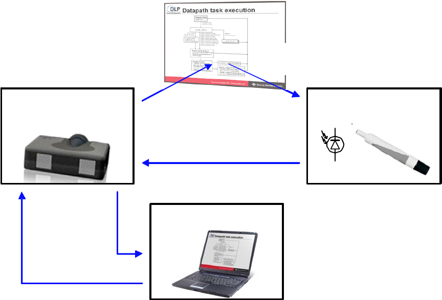
3 Overview
A PointBlank enabled DLP® projector provides an interactive white board capability without
requiring a white board or special screen. The PointBlank system is comprised of a laptop or
desktop computer with USB mouse capability, a PointBlank enabled DLP® projector and a
pointing device with a light sensor and RF transmitter. The PointBlank™ system is depicted in
Figure 1.
PointBlank-enabled
DLP® projector PBM AirDraw II
PC or laptop
feedback via RF
mouse via
USB HID
projected image
with proprietary
PointBlank encoding light sensor
measurement
image source
(VGA, DVI)
pointing oint
DLP® projector
PC or laptop
feedback via RF
mouse via
USB HID
projected image
with proprietary
PointBlank encoding light sensor
measurement
image source
(VGA, DVI)
pointing denvice
PointBlank-enabled
DLP® projector
PC or laptop
feedback via RF
mouse via
USB HID
projected image
with proprietary
PointBlank encoding light sensor
measurement
image source
(VGA, DVI)
pointing nen vce
PointBlank-enabled
DLP® projector
PC or laptop
feedback via RF
mouse via
USB HID
projected image
with proprietary
PointBlank encoding light sensor
measurement
image source
(VGA, DVI)
Interactive Pen
Figure 1 PointBlank System Diagram
The computer sources an image to the projector over VGA, DVI/HDMI or another interface. The
PointBlank enabled projector displays the source image with special encoded patterns that the
pointing device measures and transmits back to the projector over the RF link. These
measurements allow the PointBlank projector to determine the screen location that the pointing
device is directed at. Once the pointer location is known, the projector software sends it to the
computer using the USB Human Interface Device (HID) interface. Standard Microsoft drivers
intercept these coordinates just as a standard mouse device would send them and interacts with
the application being projected accordingly. While any mouse driven application can interact with
the PointBlank projector, additional application software can be developed to enhance how the
pointing device can interact with the computer.
The system does not require any calibration and can work over a wide range of screen lumens,
screen sizes, pointing device distance from screen and ambient lighting conditions. It also works
TI Confidential – NDA Restrictions 2
PointBlank Product Specification, Rev A
for any input computer source supported by the projector and independent of projector settings
such as keystone, scaling mode, etc.
The PointBlank patterns are not visible to the viewer, except for an increase in the black level and
a small decrease in the red, green and blue lumens. Depending on the DLP sequence approach,
there can be some color distortion of the black level as well. Since the PointBlank patterns affect
the projector contrast and lumens, a non PointBlank mode can also be supported and is
recommended to maintain projector specifications relative to brightness, contrast and color
points.
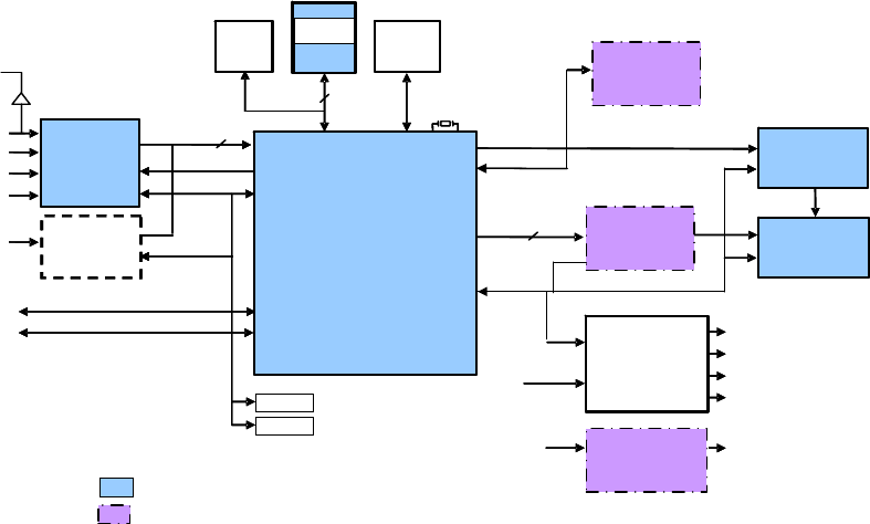
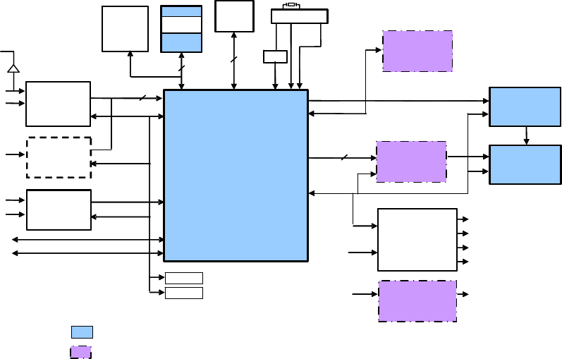
4 Detailed Description
4.1 PointBlank Hardware
The PointBlank hardware additions to the DDP2431 and DDP2230 reference designs are shown
in Figure 2 and Figure 3, respectively. They include a PointBlank FPGA inserted between the
DDP ASIC and the DMD, a RF radio transceiver and some changes to the GPIOs. Due to the
additional software memory required for the PointBlank functionality either SRAM or SDRAM is
required for DDP2230 and SRAM is required for DDP2431.
DAD2000
Control
16 pair
32
12V
EEPROM
Data
VGA
Composite
HDMI/DVI
Component
S- Video AFE1000
32MHz
Fan #1, #2, #3
POSENSE, PWRGOOD
Included in DLP Component Set along with DMD
Sequence
FLASH
TI ARM
Software
OEM ARM
Software
16
I2C
SRAM
CSP
30
Monitor
Video
Temp
HDMI/DVI
Receiver
PMD1000
DDP2431
DDR2
DMD
Motor Drive
SPI_0
SPI_1, GPIO
USB
RS-232 1.2, 2.5, 3.3, 5, 1.8, 1.8PLL
1.2, 2.5
3.3
DAD2000
Control
16 pair
32
12V
EEPROM
VGA
Composite
HDMI/DVI
Component
S- Video AFE1000
32MHz32MHz
Fan #1, #2, #3
POSENSE, PWRGOOD
Sequence
FLASH
TI ARM
Software
16
I2C
30
Monitor
Video
Temp
HDMI/DVI
Receiver
DDP2431
DMD
Motor Drive
USB
RS-232 1.2, 2.5, 3.3, 5, 1.8, 1.8PLL
1.2, 2.5
3.3
PointBlank
Radio
Transceiver
PointBlank
FPGA
Regulators
PointBlank
FPGA
Components Added for PointBlank
Figure 2 PointBlank DDP2431 Electronics Diagram
TI Confidential – NDA Restrictions 3
PointBlank Product Specification, Rev A
DAD2000
Control
16 pair
32
EEPROM
Data
VGA
Composite
HDMI/DVI
Component
S- Video
ADC
Fan #1, #2, #3
POSENSE, PWRGOOD
Included in DLP Component Set along with DMD
Sequence
FLASH
TI ARM
Software
OEM ARM
Software
16
I2C
SDRAM
Or
SRAM
BT656
27
Monitor
Video
Temp
HDMI/DVI
Receiver
PMD1000
& 1.8V
Regulator
DDP2230
DMD
Motor Drive
SPI_0
SPI_1, GPIO
USB
RS-232
DC Supplies
1.2, 2.5
3.3
Video
Decoder
XDR
DRAM
8
20MHz
CDCDLP223
320MHz
400MHz
20MHz
XCG
100MHz
DAD2000
Control
16 pair
32
EEPROM
Data
S-
ADC
Sequence
FLASH
TI ARM
Software
16
I2C
BT656
Temp
HDMI/DVI
Receiver
DDP2230
DMD
SPI_0
SPI_1, GPIO
-
Video
Decoder
12V
XDR
DRAM
8
PointBlank
Radio
Transceiver
PointBlank
FPGA
Regulators
PointBlank
FPGA
Components Added for PointBlank
Figure 3 PointBlank DDP2230 Electronics Diagram
TI Confidential – NDA Restrictions 4
PointBlank Product Specification, Rev A
4.1.1 PointBlank FPGA
The PointBlank FPGA receives LVDS image data from the DDP ASIC. Under control of the
software and sequences in the DDP ASIC, it inserts the PointBlank patterns into the normal
image data and outputs it to the DMD.
The LVDS inputs in the FPGA do not have internal termination resistors so external parallel
termination must be added on the PCB. TI recommends using filled vias for these signals at the
FPGA so the termination resistors can be placed across the vias.
The FPGA is a LFE2-12E-5FN256CB9 made by Lattice Semiconductor. Firmware and an I/O
spec for the part are available on the PointBlank Knowledge Base. Further information on the
FPGA is available on the Lattice Semiconductor website.
The FPGA requires 3.3V, 2.5V and 1.2V. The 3.3V is powered directly from the 3.3V from the
PMD1000. The 2.5V and 1.2V should be generated with linear regulators from the 3.3V. See the
reference design for details.
4.1.2 PointBlank Radio Transceiver (PBM)
The TI reference design uses an eZ430-RF2500 2.4GHz radio transceiver development board.
This board’s main components are a TI CC2500 2.4GHz transceiver and a TI MSP430F2274.
Documentation for this board and its components is available on the TI website (www.ti.com).
Additional information on antenna selection is also available.
The DDP ASIC communicates with the radio board with a SSP (SPI) bus 1. The MSP430 is the
master and the DDP ASIC is the slave. The DDP ASIC can request data from the MSP430 by
asserting a GPIO pin (request to send). See the DDP2230 PointBlank reference design
schematic for details on the connections between the DDP2230 and the eZ430-RF2500 board.
4.1.3 PointBlank Pointing Device (AirDraw II)
The PointBlank pointing device utilizes a photodiode to sense the amount of light in the projected
image. Optics in the pointing device reduces the field of view of the photodiode so the pointing
device sees a relatively small portion of the screen from a typical user distance. TI uses a 36mm
lens with a 2mm aperture located at the focal length of the lens just in front of the photodiode.
For a 75in diagonal XGA image and the pointing device located 55 in from the screen the spot
size has a horizontal diameter of about 3.7in or 62 pixels. It is important to minimize any light
reflections inside the optics housing as these can degrade performance at the edges of the
screen.
Current from the photodiode is converted to a voltage with a trans-impedance amplifier. The
output of the trans-impedance amplifier is high passed filtered to reject DC and 120Hz ambient
light sources. After filtering the signal is gained up with a programmable gain amplifier. The
output is then sampled with an ADC in a MSP430. The measurements are sent to the projector
over a 2.4GHz wireless link. The pointing device utilizes a TI CC2500 radio transceiver to
transmit messages and receive configuration. See the reference design for more details on the
pointing device electronics.
TI Confidential – NDA Restrictions 5
PointBlank Product Specification, Rev A
4.2 PointBlank Wireless
The PointBlank wireless interface is a peer to peer protocol between the projector and one or
more pointing devices. The radio operates in the 2.4GHz ISM band and is based on TI’s
SimpliciTI network protocol. At the start of operation the projector and pointing device are put in a
pairing mode to establish a link. Once linked the radio transceiver in the projector receives
measurement data from the PointBlank pointing device and can send configuration data to the
PointBlank pointing device.
Since the radio uses the 2.4GHz ISM band there is potential for interference from other wireless
devices operating in the same band such as wireless LAN (WLAN), Zigbee, Bluetooth, Wireless
USB, wireless phones, microwave ovens and others. The PointBlank wireless protocol utilizes
multiple channels and automatically selects the channel with the least interference.
4.3 PointBlank Software
The PointBlank software includes special versions of the DDP ASIC API and application software
and DLP composer libraries. In addition, software API and application code are provided for the
MSP430 in the pointing device and projector.
TI Confidential – NDA Restrictions 6