CornerTurn MRI3000A Satellite Transceiver User Manual MRI 3000 Installation Manual
CornerTurn, LLC Satellite Transceiver MRI 3000 Installation Manual
users Manaul

MRI-3000
Remote Meter Reading Interface
Installation Manual
CT1001-015
Version 0.1
25 February 2010
Use or disclosure of data contained in this document is subject to the following
statement: The data shall not be duplicated, used, or disclosed in whole or in
part, without written permission of CornerTurn, LLC. Any authorized
reproduction of technical data, or portion thereof marked with this legend must
also reproduce these markings. The U. S. Government regulates export of this
technology or software. Diversion contrary to U.S. law is prohibited.
Copyright © CornerTurn, LLC, 2010
All rights reserved. Printed in the United States of America.
Installation Guide for MRI-3000
CT1001-015, v0.1
2

Installation Guide for MRI-3000
CT1001-015, v0.1
3
Table of Contents
Table of Contents................................................................................................ 3!
Tables................................................................................................................... 3!
Figures ................................................................................................................. 4!
Introduction ......................................................................................................... 5!
Scope ........................................................................................................................... 5!
Revision History of Installation Guide ...................................................................... 5!
Contact Information.................................................................................................... 5!
Safety Information............................................................................................... 5!
FCC Notice................................................................................................................... 5!
Product Description............................................................................................ 6!
MRI-3000 Installation Overview ......................................................................... 8!
Supplies and Equipment Needed for MRI-3000 Installation ................................... 9!
Safety Considerations ...................................................................................... 11!
Installation Plan.................................................................................................12!
Complete Site Surey .................................................................................................12!
Antenna Installation.......................................................................................... 13!
MRI-3000 Controller Unit Installation .............................................................. 15!
Attaching Input Power.............................................................................................. 16!
Ethernet Installation.......................................................................................... 20!
System Power-up and Test .............................................................................. 22!
Overview of the MRI Self Test Mode ....................................................................... 22!
System Verification........................................................................................... 23!
Operation ........................................................................................................... 26!
Overview of the MRI Startup Process ..................................................................... 26!
Customer Care / Warranty................................................................................ 27!
Troubleshooting................................................................................................ 29!
CPU Operation Test – Fail........................................................................................ 29!
LAN Connectivity Test – Fail ................................................................................... 29!
Modem Power Test – Fail ......................................................................................... 29!
Modem Line of Sight Test – Fail .............................................................................. 29!
Modem Connectivity Test – Fail .............................................................................. 29!
MRI-3000 Installation Record........................................................................... 30!
Tables
Table 1: MRI-3000 Components........................................................................... 8!
Table 2: Mounting Antenna on a Pole.................................................................13!

Installation Guide for MRI-3000
CT1001-015, v0.1
4
Table 3: Mounting Antenna on a Wall.................................................................13!
Table 4: Mounting Antenna on a Roof ................................................................ 14!
Table 5: Mounting MRI-3000 Controller Unit ...................................................... 15!
Table 6: Attaching RF Cables ............................................................................. 15!
Table 7: Using MRI-3000 Power Cord ................................................................ 16!
Table 8: Using Custom Length Power Cord ....................................................... 17!
Table 9: Attaching Ethernet Cable ...................................................................... 20!
Table 10: System Verification ............................................................................. 23!
Figures
Figure 1 - MRI-3000 System Block Diagram ........................................................ 7!
Figure 2: Overview of the MRI Startup Test........................................................ 26!
Installation Guide for MRI-3000
CT1001-015, v0.1
5
Introduction
Scope
This document describes the installation and checkout procedures for the MRI-
3000 antennas and cables.
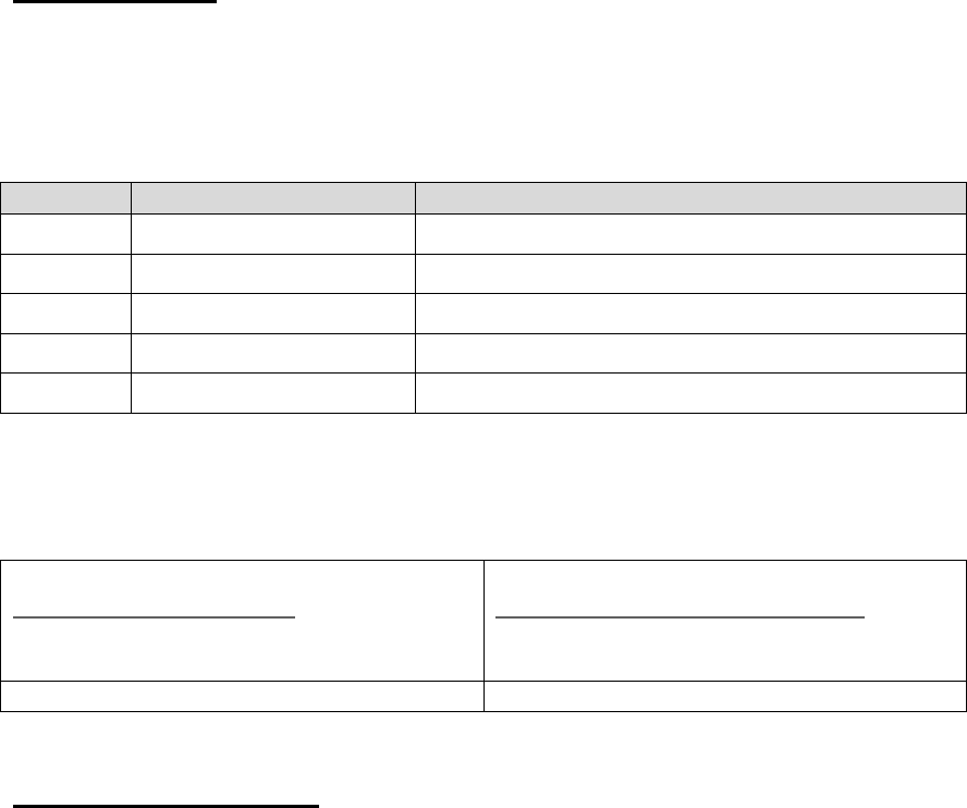
Revision History of Installation Guide
Rev No.
Date Issued
Comments
0.1
2 July 2010
First Cut Draft
0.2
19 August 2010
Second Draft
Contact Information
Please direct any questions regarding this manual to the following:
Kevin Pratt
khpratt@cornerturn.com
951-256-4206
951-735-2910 (Fax)
Scott Morgenthaler
smorgenthaler@cornerturn.com
951-256-4920
951-735-2910 (Fax)
Safety Information
FCC Notice
This equipment has been tested and found to comply with the limits for a Class A
digital device, pursuant to part 15 of the FCC Rules. These limits are designed to
provide reasonable protection against harmful interference when the equipment
is operated in a commercial environment. This equipment generates, uses, and
can radiate radio frequency energy and, if not installed and used in accordance
with the instruction manual, may cause harmful interference to radio
communications. Operation of this equipment in a residential area is likely to
cause harmful interference in which case the user will be required to correct the
interference at their expense.

Installation Guide for MRI-3000
CT1001-015, v0.1
6
DANGER! Avoid Power Lines!
When following instructions in this
guide to install and connect the
antenna and connections, take extreme
care to avoid contact with overhead
power lines, lights, and other power
circuits.
Contact with these items may be fatal.
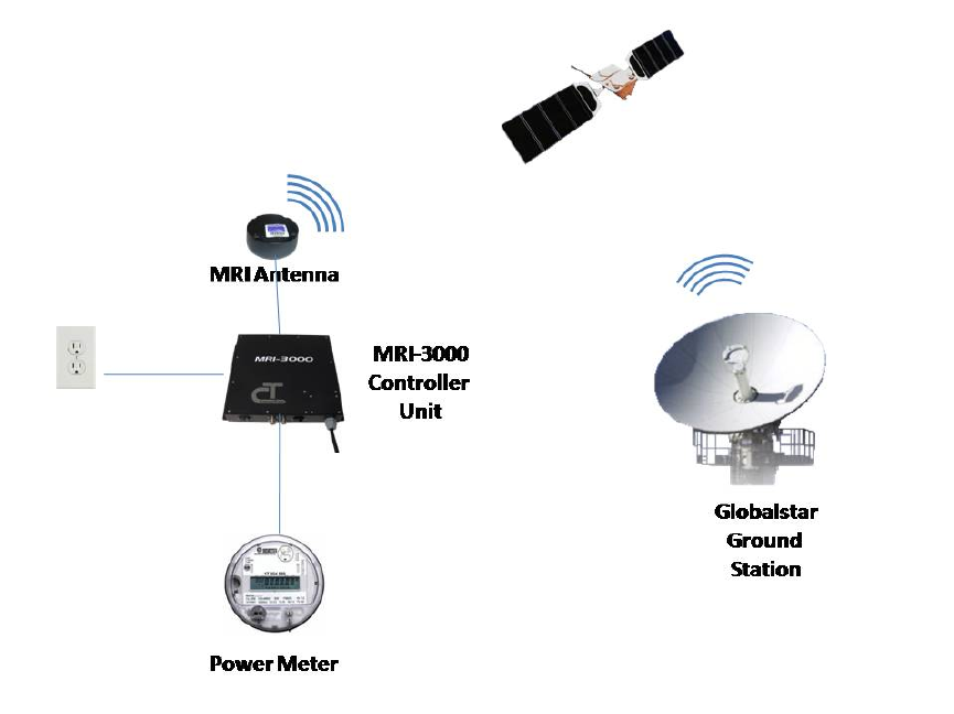
Product Description
The MRI-3000 system provides a satellite-based path to communicate with
Ethernet equipped remotely installed metering / logging equipment. (see Figure
1) The system consists of an Antenna mounted high to provide an unobstructed
view of the sky, the MRI-3000 Controller Unit, and interconnection cabling.
The MRI-3000 Controller Unit provides a single point to attach the Ethernet cable
from the metering equipment, as well as 110vac to power the system. Two coax
cables connect the MRI-3000 Controller Unit to the Antenna.
An external system, such as an MV-90 server, can retrieve meter information by
connecting to an IP address representing the remote metering equipment. When
satellite coverage is established, a TCP/IP connection is established between the
remote metering equipment and the external system as if the meter was
connected directly to the external system.
This product is designed for use with Globalstar-approved antennas only. As of
the publication date of this manual, approved antennas include the Globalstar
Active Magnetic Patch Antenna (GAT-17MP), Globalstar Passive Patch Antenna
(GAT-17PP), and Globalstar Maritime Mount Antenna (GAZT-17MR). Note that
the antenna cables provided with this product are specifically tuned for the MRI-
3000. Please contact CornerTurn if you would like to use a different antenna or
antenna cables different than those available with the product. Failure to do so
will void the warranty. Contact information is provided on the front of this manual.
Installation Guide for MRI-3000
CT1001-015, v0.1
7
Figure 1 - MRI-3000 System Block Diagram
Installation Guide for MRI-3000
CT1001-015, v0.1
8
MRI-3000 Installation Overview
This procedure covers the installation of the Antenna, MRI-3000 Controller Unit
and interconnecting cables. It can be easily adapted to different types of
installation sites.
This procedure assumes the system will be installed in accordance with all local
electrical and building codes, including requirements for grounding and lightning
protection.
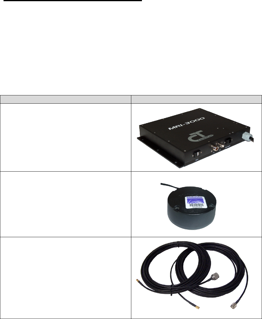
Table 1: MRI-3000 Components
Item
Description
MRI-3000 Controller Unit
Globalstar Antenna
GAT-17MP – Active Magnetic Patch
Antenna
GAT-17PP – Passive Patch Antenna
GAZT-17MR – Maritime Mount
Antenna
Coax Antenna Cable Sets
1’ Xmit & Rcv cables (passive
antenna only)
-or-
36’ Xmit & Rcv cables
-or-
66’ Xmit & Rcv cables
-or-
contact CornerTurn for other lengths
Installation Guide for MRI-3000
CT1001-015, v0.1
9
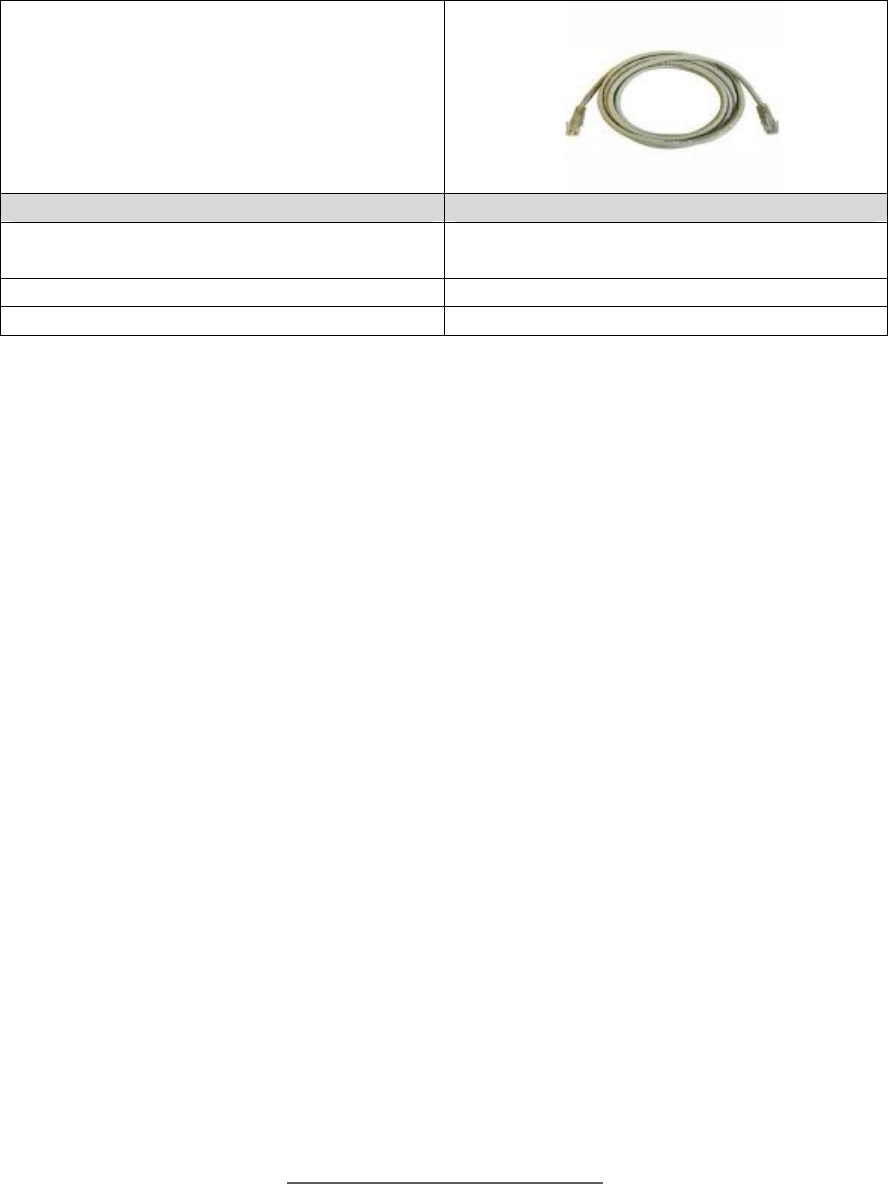
Ethernet cable to user metering
equipment (<100 meters long)
Optional Items
Description
USB Null Modem Cable
Used for System Verification at time of
installation.
Antenna Mount (various configurations)
Supplies and Equipment Needed for MRI-3000 Installation
We recommend the installer bring the following additional items to the installation
site to carry out the installation:
REQUIRED
· Tools
o (2) 5/16” open end wrench for SMA connectors on cables
o Cordless drill with screwdriver attachment
o Drill bits (various sizes for wood and/or concrete)
o Caulking gun
o Fish tape
o Side cutters
o Screwdriver, phillips head #2
o Adjustable crescent wrench (opens to 1”)
· Material
o Mounting screws or other fasteners (qty 6) for MRI-3000 box
o Mounting screws or other fasteners (qty 4) for Globalstar antenna
o Caulking Compound
RECOMMENDED
· Support Equipment
o Printout of Globalstar Call Times for the installation site (within 200
miles) Obtain from http://calltimes.globalstar.com
o Globalstar GSP-1600 Mobile Satellite phone
o Laptop with available USB port and Terminal SW (WinTerm, PuTTY, or
equivalent)

Installation Guide for MRI-3000
CT1001-015, v0.1
10
o Obtain PuTTY software from
http://www.chiark.greenend.org.uk/~sgtatham/putty/download.html
o USB Null Modem Cable, Type A to Type A (CAUTION: DO NOT use a
standard USB Type A to Type A cable to connect to the MRI-3000
Controller Unit. Equipment damage may occur.)
o Camera (phone camera is okay)
· Tools
o Electric drill
o Screwdriver, Phillips #1
o Torque wrench for SMA connector, 5/16” open end (3-5 in/lbs)
o Marking pen
o Extension ladder
o Step ladder, 6 foot
o Utility knife
o Cable stripper 16 awg
o Tape measure
o Cable tie tension tool
o Extension cord
o Drop Light
o Flash Light
· Material
o Electrical Tape
o Butyl Rubber Sealing Tape
o Concrete anchors
o Drywall anchors
o Cable tie mounts
o Cable ties
o EMT conduit
o Conduit clamps
o Caulking compound
o Wire nuts (Required if replacing supplied power cord)
o 16 awg, 3 conductor power cable (Required if replacing supplied power
cord)

Installation Guide for MRI-3000
CT1001-015, v0.1
11
Safety Considerations
When mounting the antenna or junction box, take extreme care to avoid contact
with overhead power lines, electric lights, and power circuits. Contact with power
lines, electric lights, or power circuits can be fatal. It is recommended to mount
the antenna at least 10 feet away from any overhead power lines.
DO NOT connect a standard USB cable to the MRI-3000 Controller Unit Test
port for any purpose. Use only a USB Null Modem Cable when connecting to the
Test port. Connecting any USB cable other than the one specified in Table 1
may damage the MRI-3000 Controller Unit.

Installation Guide for MRI-3000
CT1001-015, v0.1
12
Installation Plan
Complete Site Survey
Conduct a site survey and determine the optimal mounting location for the
antenna and the MRI-3000 Controller Unit. The antenna needs to be mounted to
provide the best, unimpeded view of the entire sky down to an elevation of 10
degrees above the horizon. The antenna performance will be the best from
higher elevation angles and progressively worse toward the horizon. It should be
at least 5 feet away from other transmitting antennas. Trees, leaves, limbs, hills,
and walls are all obstructions that will block the antenna signal. The selected
antenna mounting location should be high enough to provide a clear line of sight
above those obstructions.
The MRI-3000 Controller Unit is not waterproof and must be mounted in an
enclosed area. The Ethernet cable that connects the Controller Unit to the user
equipment must be less than 100 meters in length. The MRI-3000 Controller
Unit must also be mounted close enough to the antenna, to safely run the RF
cables (36 or 66 feet) that were ordered with the system. The MRI-3000
Controller Unit requires a 110VAC input. The Unit comes with an attached 6 foot
power cord with a NEMA 5-15 plug. If a longer power cord is required, one can
be easily installed to replace the supplied cable. This procedure is discussed in
greater detail in Step 4, Attaching Input Power.

Installation Guide for MRI-3000
CT1001-015, v0.1
13
Antenna Installation
Table 2: Mounting Antenna on a Pole
Procedure
Comments
1. Select a mounting location on the
pole so that the antenna will be
clear of any obstacles and power
lines.
In general, mounting the antenna as far
up the pole as possible will minimize
obstructions.
2. Select the mounting hardware to
be used to mount the bracket to
the pole.
3. Using a template or the bracket,
mark the hole locations on the
pole where the bracket will be
mounted.
For wood poles, drill pilot holes for the
lag bolts.
For concrete poles, appropriately sized
concrete anchors should be used.
4. Drill the holes for the mounting
bolts/hardware.
5. Anchor the bracket into the pole
with the mounting hardware that
was selected in step 2.
Table 3: Mounting Antenna on a Wall
Procedure
Comments
1. Select a mounting location on the
building wall so that the antenna
will be above the roof line and
provide a clear view of the sky
down to 10 degrees above the
horizon in all directions.
On buildings with flat roofs, any wall
can be used.
On buildings with gabled roofs, the
antenna must be mounted near the
top of the gabled wall.
2. Select the mounting hardware to
be used to mount the bracket to
the wall.
3. Using a template or the bracket,
mark the hole locations on the wall
where the bracket will be mounted.
For wood walls, drill pilot holes for the
lag bolts.
For concrete walls, appropriately sized
concrete anchors should be used.
4. Drill the holes for the mounting
bolts/hardware.
5. Anchor the bracket into the wall
with the mounting hardware that
was selected in step 2.

Installation Guide for MRI-3000
CT1001-015, v0.1
14
6. Caulk all wall penetrations to
prevent water intrusion.
Table 4: Mounting Antenna on a Roof
Procedure
Comments
1. Select a mounting location on the
roof so that the antenna will have a
clear view of the sky down to 10
degrees above the horizon in all
directions.
2. Select the mounting hardware to be
used to mount the bracket to the
roof.
3. Using a template or the bracket,
mark the hole locations on the roof
where the bracket will be mounted.
For wood roofs, drill pilot holes for the
lag bolts.
For concrete roofs, appropriately sized
concrete anchors should be used.
4. Drill the holes for the mounting
bolts/hardware.
5. Anchor the bracket into the wall with
the mounting hardware that was
selected in step 2.
6. Caulk all roof penetrations to
prevent water intrusion.

Installation Guide for MRI-3000
CT1001-015, v0.1
15
MRI-3000 Controller Unit Installation
Table 5: Mounting MRI-3000 Controller Unit
Procedure
Comments
1. Determine mounting location for
MRI-3000 Controller Unit in the
enclosed area.
The MRI-3000 is not weatherproof and
must be mounted in an enclosed area.
The unit can be mounted horizontally
on a flat surface or vertically on a wall.
2. Mark the mounting hole locations of
the Controller Unit on the mounting
surface.
3. Drill holes for mounting screws or
anchors.
4. Mount the MRI-3000 and secure
with screws and appropriate
anchors where required.
Use concrete anchors in concrete and
drywall anchors if mounting to drywall
between studs.
Table 6: Attaching RF Cables
Procedure
Comments
1. Connect and hand tighten the N
male connector of the transmit
cable to the TX connector on the
MRI-3000 Controller Unit.
The transmit cable has a type N male
connector on one end and an SMA
male connector on the other end.
2. Connect and hand tighten the TNC
male connector of the receive cable
to the RX connector on the MRI-
3000 Controller Unit.
The receive cable has a TNC male
connector on one end and SMA female
connector on the other end.
3. Drill a hole where you plan to run
the RF cables out of the enclosed
area.
If using conduit, drill the hole large
enough for the conduit to penetrate the
enclosed area. If not using conduit,
drill the hole just large enough to feed
the cables through.
4. If conduit is required, make your
conduit run from the antenna into
the wall penetration.
If weatherproof RF cabling is being
used, conduit may not be required.

Installation Guide for MRI-3000
CT1001-015, v0.1
16
5. From the antenna end, feed fish
tape through the conduit back to the
exposed RF cables.
NOTE: If conduit is not used, feed
the fish tape through the hole in the
enclosed area.
6. Tape the cables to the fish tape so
that the strain is not directly on the
connectors when pulling the cables
through.
7. Pull the RF cables through the
conduit or the opening and up to the
antenna.
NOTE: The antenna cables are
connected to the MRI-3000 Controller
Unit. Be careful not to pull them too far
and damage the cables or the
connectors.
8. Connect the transmit cable (male
SMA) connector to the antenna’s
SMA female connector.
NOTE: SMA connectors should be
tightened to 3-5 in/lbs
Do not over tighten
9. Connect the receive cable (female
SMA) connector to the antenna’s
SMA male connector.
NOTE: SMA connectors should be
tightened to 3-5 in/lbs
Do not over tighten
10. If the cable connections will be
exposed to the weather, wrap them
with butyl rubber sealing tape.
11. Go to the outside of the enclosed
area where the RF cable
penetration was made and caulk
the opening to prevent water
intrusion.
Attaching Input Power
Table 7: Using MRI-3000 Power Cord
Procedure
Comments
1. No action is necessary if the
supplied power cord will reach a
110VAC receptacle.
Unit is prewired with a 6 foot power
cord.
Installation Guide for MRI-3000
CT1001-015, v0.1
17
Table 8: Using Custom Length Power Cord
Procedure
Comments
1. Make sure the MRI-3000 Controller
Unit is unplugged.
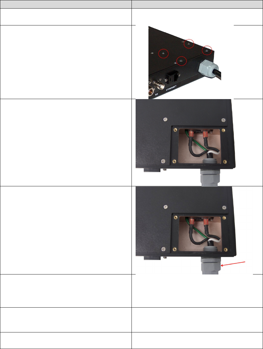
2. Remove the 4 screws from the top
corner access cover on the MRI-
3000 Controller Unit.
3. Remove the access cover to
expose the AC input wiring.
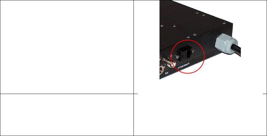
4. With an open ended crescent
wrench, loosen the outer plastic nut
on the power cord so that the cord
can slide in and out of the Controller
Unit.
5. Gently push the power cord into the
Controller Unit until each lead has
approximately 4” of length inside
the access cover.
6. Cut the Line, Neutral, and Ground
wires inside the access cover to
approximately 4” in length.
7. Remove the supplied power cord
from the coupler and discard.

Installation Guide for MRI-3000
CT1001-015, v0.1
18
8. Strip 1” off the ends of the Line,
Neutral, and Ground wires that
remain inside the access cover.
9. Strip off approximately 2” of
insulation from the customer
supplied power cable.
10. Strip 1” off the ends of the Line,
Neutral, and Ground wires of the
customer supplied power cable.
11. Feed the power cable through the
nut and into the access cover area.
12. Twist the two ground wires (green
or green & yellow) together with
pliers.
13. Trim the cable if necessary so that
the wire nut will cover the exposed
wire.
14. Apply a wire nut to the grounds and
tighten securely.
15. Wrap the wire nut and wires with
electrical tape.
16. Twist the two neutral wires (white or
blue) together with pliers.
17. Trim the cable if necessary so that
the wire nut will cover the exposed
wire.
18. Apply a wire nut to the neutrals and
tighten securely.
19. Wrap the wire nut and wires with
electrical tape.
20. Twist the two hot wires (black or
brown) together with pliers.
21. Trim the cable if necessary so that
the wire nut will cover the exposed
wire.
22. Apply a wire nut to the hot wires
and tighten securely.
23. Wrap the wire nut and wires with
electrical tape.
24. Push the wires down into the cable
access area.
25. With an open ended crescent
wrench, tighten the outer plastic nut
around the power cord so that it
cannot slide in and out of the
Controller Unit.

Installation Guide for MRI-3000
CT1001-015, v0.1
19
26. Insert the cable access cover and
secure with the 4 screws removed
earlier.

Installation Guide for MRI-3000
CT1001-015, v0.1
20
Ethernet Installation
Note: For outside Ethernet cable runs, it is recommended to use conduit.
Exterior grade or direct burial cable should be used outdoors if not using conduit.
Direct burial cable should be buried 6-8 inches into the ground and at least that
far away from power lines and other electrical noise sources.
Table 9: Attaching Ethernet Cable
Procedure
Comments
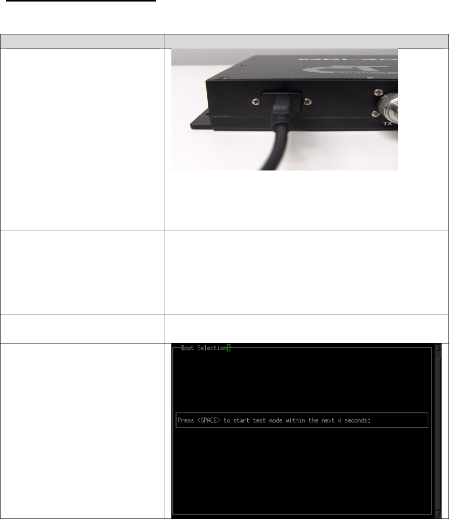
1. Determine where the Ethernet cable
will penetrate the enclosed area.
NOTE: If the user device and the MRI-
3000 Controller Unit are co-located in
the enclosed area, connect the
Ethernet cable between the user
device Ethernet port and the Controller
Unit Ethernet Port and continue to
Section 6, System Power Up and Test.
2. Drill a hole in the enclosed area for
the Ethernet cable.
If using conduit, drill the hole large
enough for the conduit to penetrate the
enclosed area. If not using conduit,
drill the hole just large enough to feed
the Ethernet cable through.
3. If you’re using conduit between the
user device and the enclosed area,
install the conduit run from the user
device and into the hole just drilled.
4. Feed the fish tape through the hole
from outside the enclosed area.
5. Tape the Ethernet cable to the fish
tape so that the strain is not directly
on the connector when pulling the
cable through.
6. Pull the Ethernet cable to the user
device and attach it to the user
device Ethernet port, leaving an 8-
12 inch service loop.
If you need to terminate the cable with
an RJ-45 connector, wire it straight-
through using either the T-568A or T-
568B standard. The same standard
must be applied to each end.
7. If you’re using direct burial cable,
bury it in the ground at the
recommended depth.
Installation Guide for MRI-3000
CT1001-015, v0.1
21
8. Go back to the enclosed area and
connect the Ethernet cable to the
Ethernet port on the MRI-3000
Controller Unit.
9. Go to the outside of the enclosed
area where the Ethernet cable
penetration was made and caulk
the opening to prevent water
intrusion.

Installation Guide for MRI-3000
CT1001-015, v0.1
22
System Power-up and Test
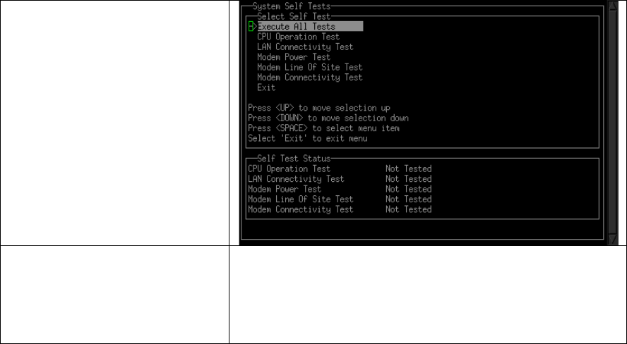
Overview of the MRI Self Test Mode
The MRI Self Test Mode has 5 tests that can be used to check out the MRI-3000
system. The tests can be run individually or as a group to verify a successful
installation.
1. Execute All Tests – This test runs each of the 5 individual tests
sequentially.
2. CPU Operation Test – Verifies CPU booted properly by checking last boot
log for errors. Status will be either Pass or Fail.
3. LAN Connectivity Test – Verifies network connectivity to the user device.
Status will be either Pass or Fail.
4. Modem Power Test – Cycles power on the modem and checks that the
modem self test is okay. Status will be either Pass or Fail.
5. Modem Line Of Sight Test – Checks to see if all modems have signal
strength (RSSI) greater than 0 and can establish contact with satellite.
Can take up to 1 minute to complete. Status will be either Pass or Fail.
NOTE: Requires a satellite to be visible in order to pass.
6. Modem Connectivity Test – Checks to see if the MRI-3000 can connect to
the ground based MRI Server via the satellite. Status will be either Pass
or Fail.
NOTE: Requires a satellite to be visible in order to pass.
Installation Guide for MRI-3000
CT1001-015, v0.1
23
System Verification
Table 10: System Verification
Procedure
Comments
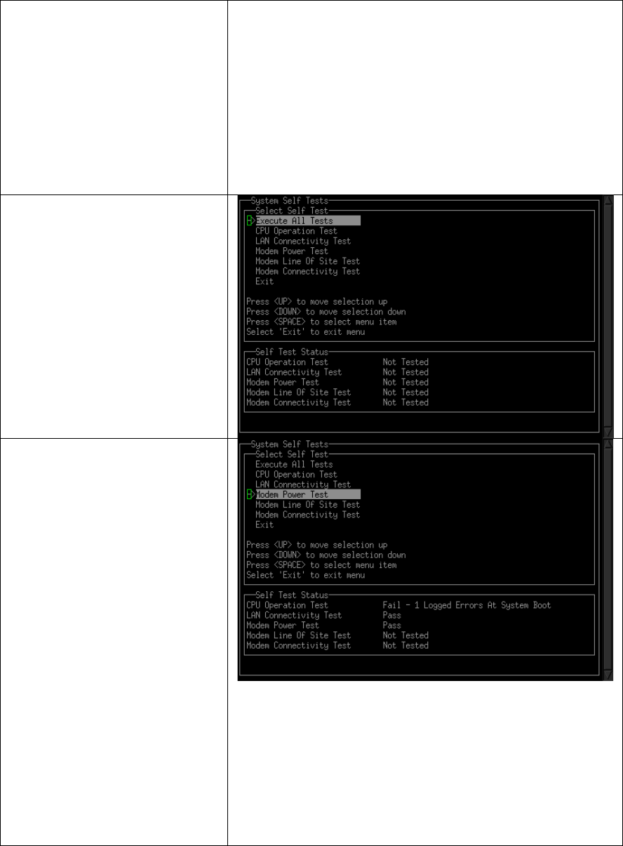
1. Using the USB Null
Modem cable
specified in Table 1,
connect a Laptop to
MRI-3000 Controller
Unit diagnostic Test
port.
CAUTION: Use of
any standard USB to
USB cable may
result in equipment
damage.
2. On the laptop, start
the Terminal
Program and
configure the serial
port.
Serial Settings:
Baud (speed): 115,200
Data Bits: 8
Stop Bits: 1
Parity: No Parity
Flow Control: XON/XOFF
3. Plug in the MRI-3000
Controller Unit.
4. In terminal window,
initiate the self test
by pressing the
<SPACE> bar within
5 seconds after the
Boot Selection is
displayed.
Installation Guide for MRI-3000
CT1001-015, v0.1
24
5. Review the
Globalstar OSAT Call
Times and find the
next available
satellite pass. The
test should be run
with at least 2
minutes of satellite
visibility remaining.
6. Select the Execute
All Tests using the
<Up> or <Down>
arrows to highlight
and then pressing
the <SPACE> bar.
7. Monitor the Self Test
Status window and
verify that each Test
Status shows a
status of Pass. If any
test indicates Fail,
refer to the
Troubleshooting
section to repair the
failure and then
return to step 3 of
System Verification.
If all tests Pass,
continue to the next
step.
NOTE: A satellite
must be in view for
the Modem Line of
Site Test and the
Modem Connectivity
Test to Pass.
Installation Guide for MRI-3000
CT1001-015, v0.1
25
8. Select Exit by using
the <Down> arrow to
highlight and then
press the <SPACE>
bar. This will reboot
the MRI-3000
Controller Unit.
9. Disconnect the USB
transfer cable from
the MRI-3000
Controller Unit and
turn off the laptop.
The MRI-3000 installation was successful and is
now configured for unattended operation.
Installation Guide for MRI-3000
CT1001-015, v0.1
26
Operation
The MRI-3000 System is now configured and ready for operation. It
requires no further action by an installer or operator to function. If power is lost,
the MRI-3000 will startup automatically when power is restored.
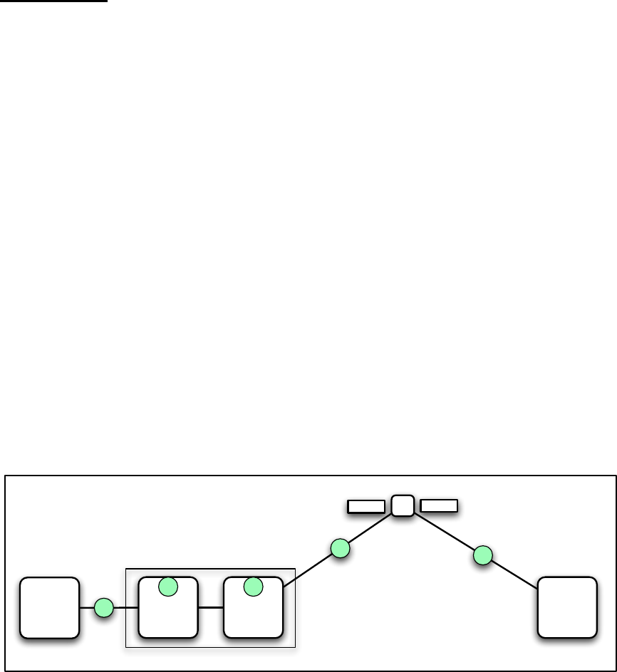
Overview of the MRI Startup Process
Five basic things are verified every time the MRI-3000 starts up:
1. The internal processor
2. The satellite modem
3. Ethernet connectivity to the User Device
4. That the MRI-3000 can see / contact the satellite
5. That the MRI-3000 can contact the MRI router at the other end of the
Satellite path
Figure 2: Overview of the MRI Startup Test
Proc
User
Device Modem MRI
Router
MRI-3000 5
1 2
3
4

Installation Guide for MRI-3000
CT1001-015, v0.1
27
Customer Care / Warranty
Call Customer Care (1-877-452-5782) for all Subscription Related and Warranty
Issues. The ESN and MDN numbers of the unit will be required, along with the
Subscriber Account Name
The MRI-3000 comes with the following Product Warranty.
LIMITED WARRANTY. CornerTurn provides a one (1) year Limited Product
Warranty that the Meter Reading Interface (MRI) Terminal (the "Terminal") shall
be free from defects in workmanship and materials under normal use and
service. CornerTurn’s obligation under this warranty is limited to repairing and
replacing, at CornerTurn’s election, any Terminal, that within twelve (12) months
of initial date of shipment is determined to be defective in material or
workmanship upon examination by CornerTurn, without charge for parts or labor.
CornerTurn reserves the right to use new or refurbished parts and/or the current
technology for any repairs/replacements, provided that they maintain form, fit,
function compatibility. Customer is to provide CornerTurn with notice of the
defect, including all reasonable available details regarding the nature of the
nonconformity or defect, and request a Returned Merchandise Authorization. Any
Terminal must be returned to CornerTurn; no field repairs will be performed. This
warranty shall not apply to repair or replacement necessitated by accident,
disaster, customer supplied interfacing, unauthorized modification or repairs,
misuse or abuse. Except where prohibited by law, any Terminal or part replaced
under warranty by CornerTurn shall become the property of CornerTurn. The
performance of this limited warranty does not extend the warranty period for any
Terminal beyond the original limited warranty period. ALL OTHER STATUTORY
AND IMPLIED WARRANTIES (INCLUDING IMPLIED WARRANTY OF
MERCHANTIBILITY AND FITNESS FOR A PARTICULAR PURPOSE) ARE
EXCLUDED except warranty of title.
For$Warranty$Issues$contact$Customer$Care
Installation Guide for MRI-3000
CT1001-015, v0.1
28
MRI-3000 Installation Checklist
Antenna located with a clear view of sky down to 10 degrees elevation
Antenna mounted
MRI-3000 Controller Unit mounted
RF cables connected to Antenna
RF cables connected to MRI-3000 Controller Unit
Power Cable connected to MRI-3000 Controller Unit
Ethernet cable connected to MRI-3000 Controller Unit
Ethernet cable connected to user equipment
System Verification testing passed with all tests having status of Pass
All building/enclosure penetrations caulked and/or sealed.
All cables securely mounted
Site cleanup completed

Installation Guide for MRI-3000
CT1001-015, v0.1
29
Troubleshooting
Find the Failure Condition that you are troubleshooting. Start with the first step
and continue in order until you find the cause of the failure. Once you’ve
corrected the failure, return to the System Verification testing.
CPU Operation Test – Fail
1. Cycle power on MRI-3000 Controller Unit.
2. Call Customer Support Center.
LAN Connectivity Test – Fail
1. Verify Ethernet Cable is connected to end user equipment.
2. Verify Ethernet Cable is connected to MRI-3000 Controller Unit.
3. Verify Ethernet Cable is wired straight through.
4. Cycle power on MRI-3000 Controller Unit.
5. Replace Ethernet Cable
6. Call Customer Support Center.
Modem Power Test – Fail
1. Cycle power on MRI-3000 Controller Unit.
2. Call Customer Support Center.
Modem Line of Sight Test – Fail
1. Check OSAT Globalstar Call Times and make sure test is run during an
available call time.
2. Cycle power on MRI-3000 Controller Unit.
3. Call Customer Support Center.
Modem Connectivity Test – Fail
1. Check OSAT Globalstar Call Times and make sure test is run during an
available call time and the test has time to complete.
2. Record the status information from the failed test and call Customer
Support Center.

Installation Guide for MRI-3000
CT1001-015, v0.1
30
MRI-3000 Installation Record
1. Date
2. Globalstar Phone Number
3. MRI-3000 Serial Number
4. Built-In Test Completion
1 – CPU Operation _______
2 – LAN Connect _________
3 – Modem Power ________
4 – Modem LOS _________
5 – Modem Conn._________
Time of Completion _______
5. Name of Installer
6. Pictures taken of the
installation
Antenna __________
MRI-3000 ___________
User Equipment __________
7. Pictures of the location
taken from the Antenna
looking in all directions
8. Describe any other
antennas or equipment
nearby