Corning Optical Communication Wireless 1C85P19L70A17 OPTICAL NETWORK EVOLUTION DAS User Manual GENII
Corning Optical Communication Wireless OPTICAL NETWORK EVOLUTION DAS GENII
UserManual.wiki
>
Corning Optical Communication Wireless
>
1C85P19L70A17 User Manual
>
User Manual
Contents
1.
User Manual
2.
Users Manual
User Manual
Navigation menu
Upload a User Manual
Namespaces
Wiki Guide
HTML
PDF
Info
Views
User Manual
Discussion / Help
Navigation
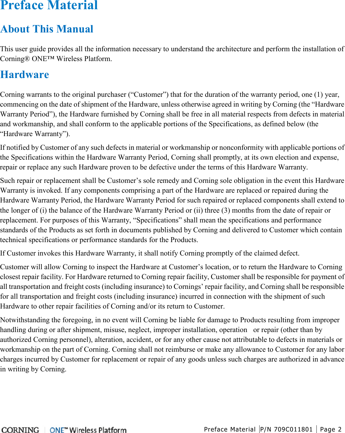
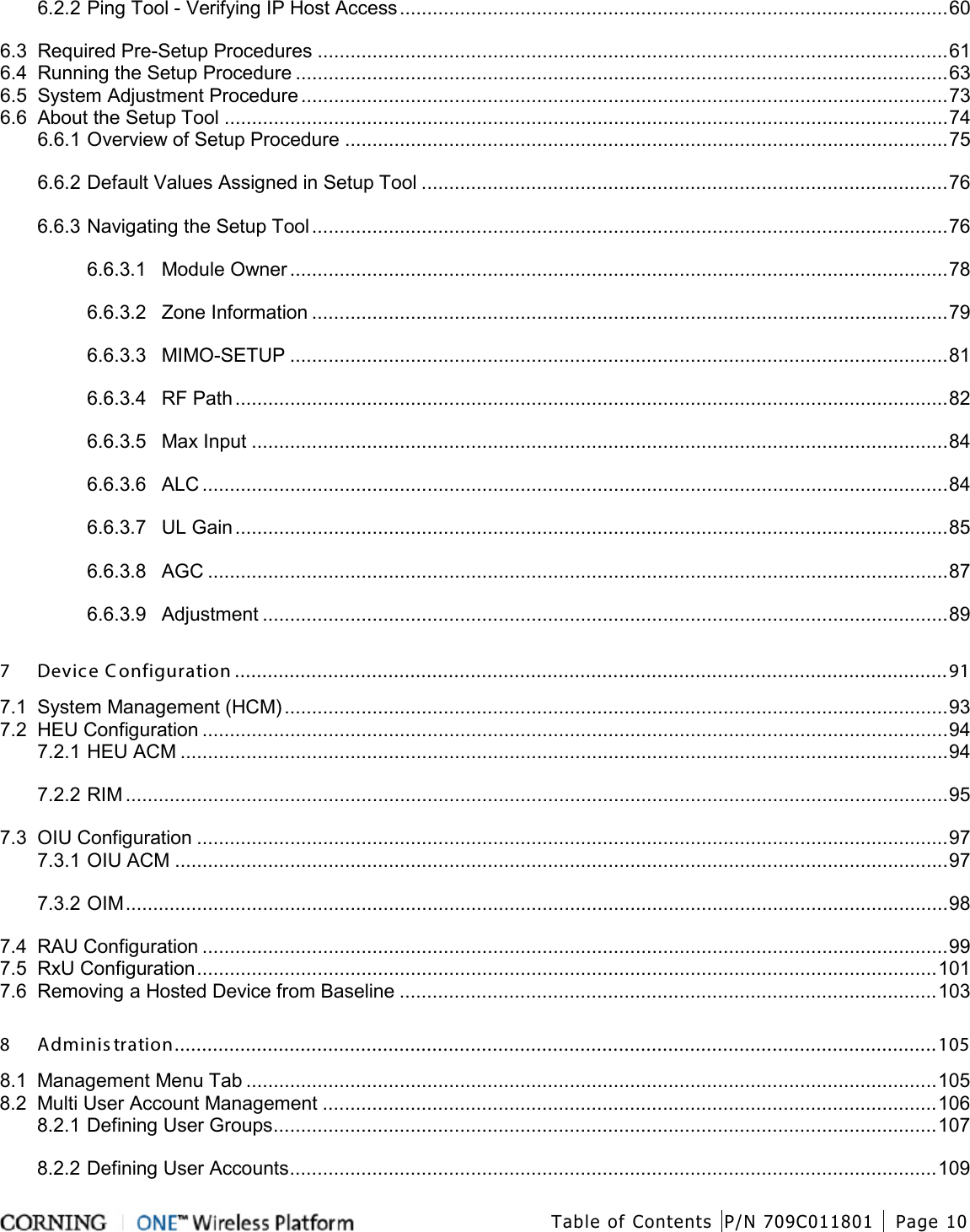
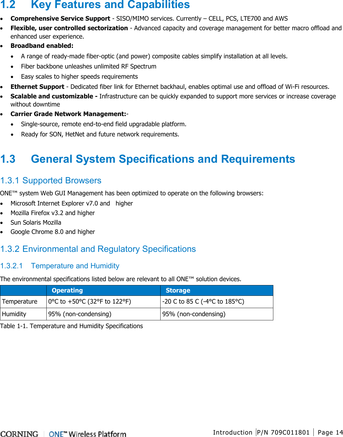
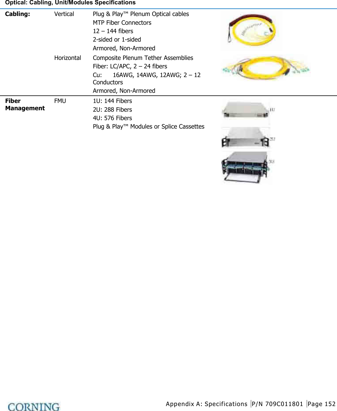
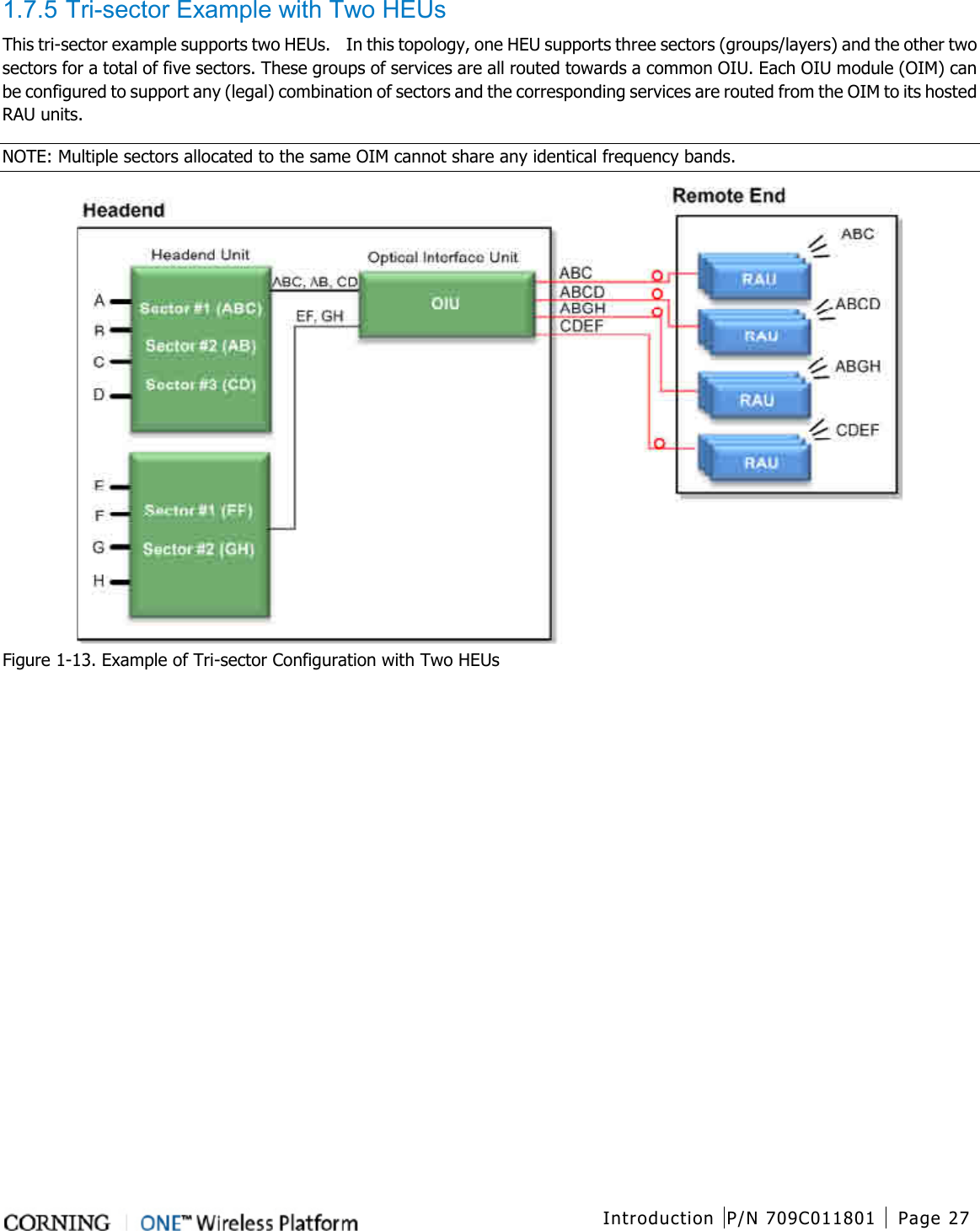
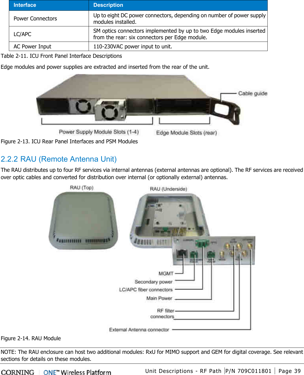
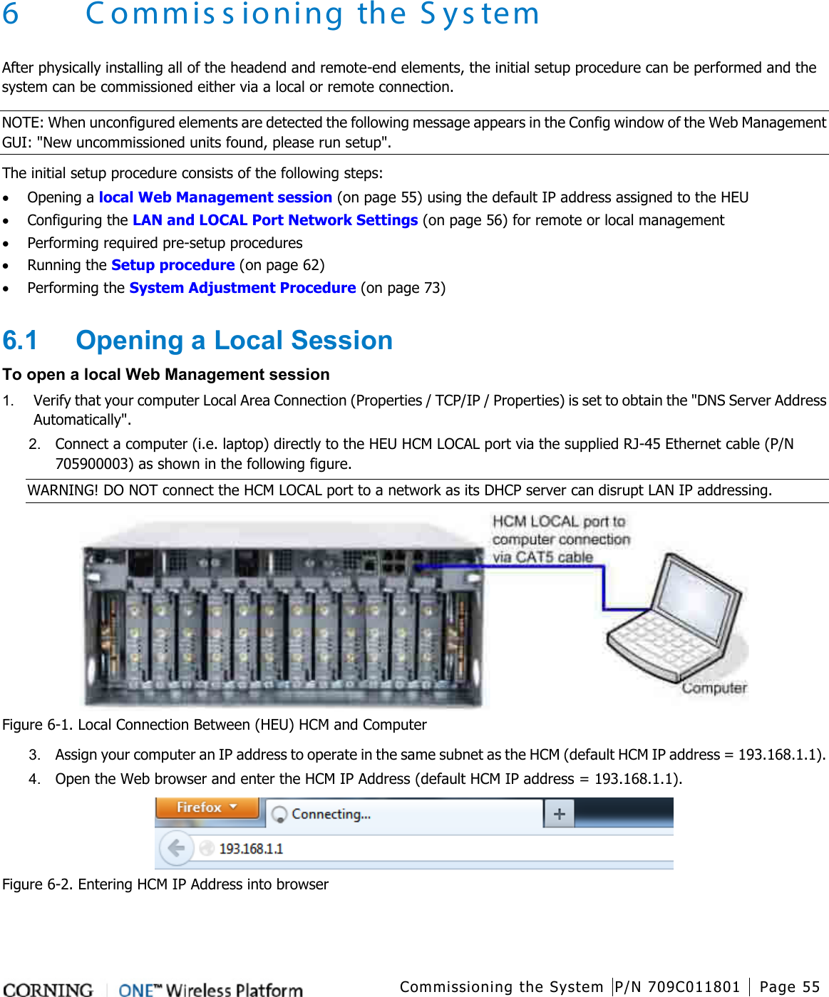
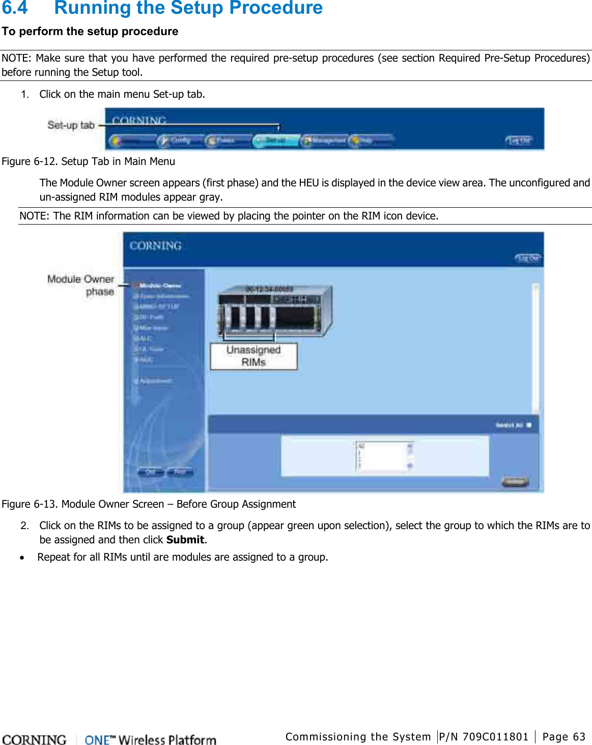
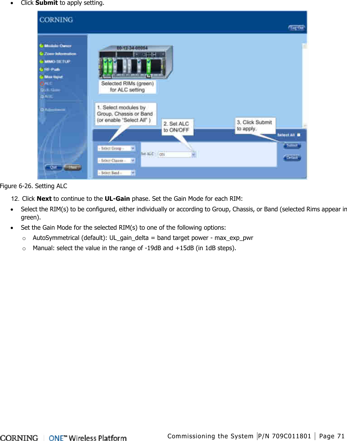
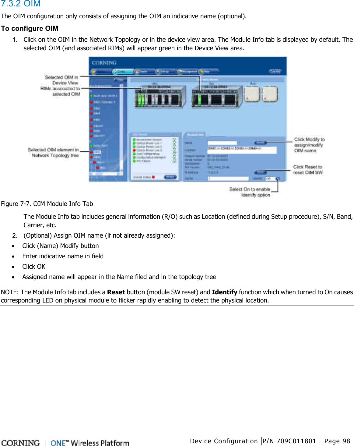
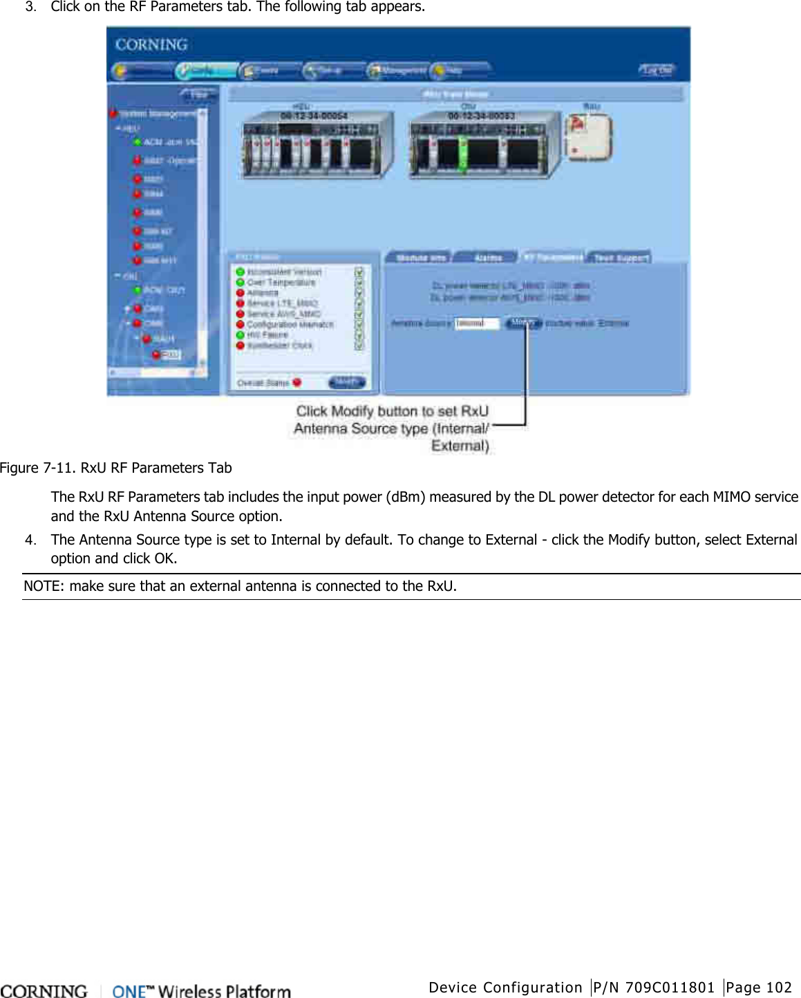
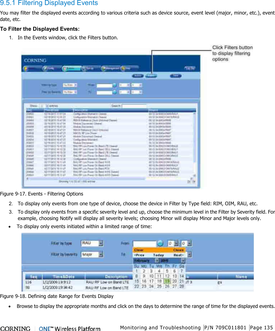
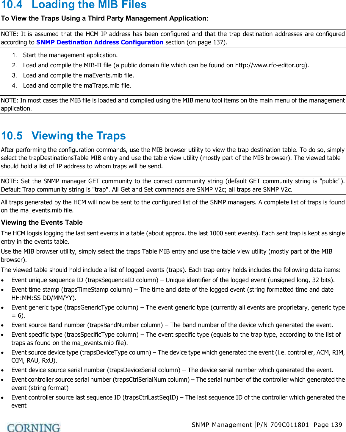
![Introduction P/N 709C011801 Page 16 1.3.4 Dimensions and Weight of Units The tables below describe the physical specifications of the ONE™ units. Table 1-6. RF Path Headend Units Unit Dimensions (H x W x D) US [International] Weight: lbs [kg] HEU 7 x 17.3 x 18.95 in [177.8 x 440 x 481.7 mm] Chassis: 37 lbs [16.8 kg] Per RIM: 1.9 lbs [0.9 kg] Per RIX: 1.54 lbs [0.7 kg] HCM: 2.2 lbs [1.0 kg] PSM: 1.98 lbs [0.9 kg] OIU 7 x 17.3 x 18.95 in [177.8 x 440 x 481.7 mm] Chassis: : 37 lbs [16.8 kg] Per OIM: 0.7Kg [1.5lbs] Per OIX: 1.54 lbs [0.7 kg] ACM: 2.2 lbs [1.0 kg] PSM: 1.98 lbs [0.9 kg] Table 1-7. RF Path Remote Units Unit Dimensions (H x W x D) US [International] Weight: lbs [kg] ICU 17 x 15 x 19.2 in [430.5 x 379.8 x 488 mm] 5.5 lbs [2.5 kg] – without PSM RAU (including mounting bracket) 13.1 x 13.1 x 4 in [332.7 x 332.7 x 101.6 mm] RAU only = 7.05 lbs [3.2Kg]; RAU+RxU+GEM = 14 lbs [5.5 Kg] Table 1-8. Digital Path Units Unit Dimensions (H x W x D) US [International] Weight: lbs [kg] GEM 1.28 x 3.79 x 5.95 in [32.7 x 96.3 x 151.3 mm] 1.1 lbs [0.5 kg] GEU-S 5.01 x 10.51 x 3.26 in (including mounting bracket) [127.5 x 267 x 83 mm] 2.64 lbs [1.2 kg] 1.3.5 Optical Specifications Parameter Specification Optical Output Power <9 dBm Max. Optical Budget 5 dB Optical Connector OIM: MTP connector RAU: LC/APC SM Fiber Type Corning SMF-28 or Compatible Wavelength 1310±10nm (Standard) Maximum Distance (headend to remote end) 2Km (SMF) Table 1-9. Optical Specifications](https://usermanual.wiki/Corning-Optical-Communication-Wireless/1C85P19L70A17.User-Manual/User-Guide-2036299-Page-16.png)
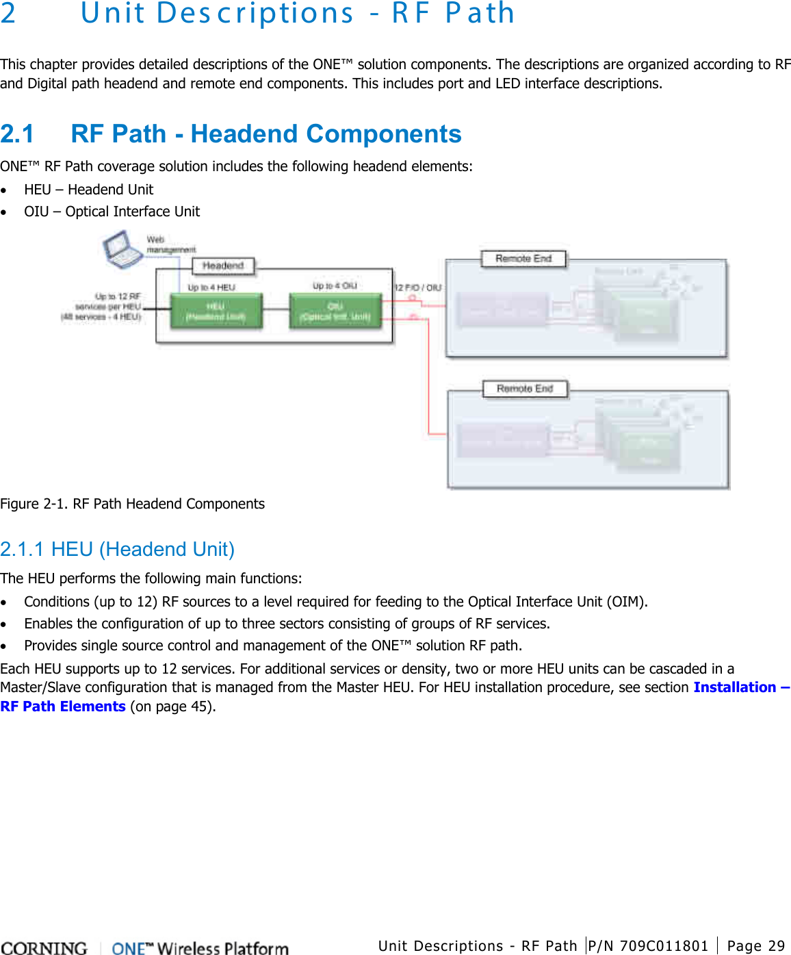
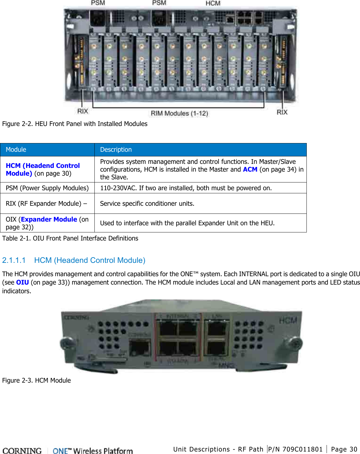
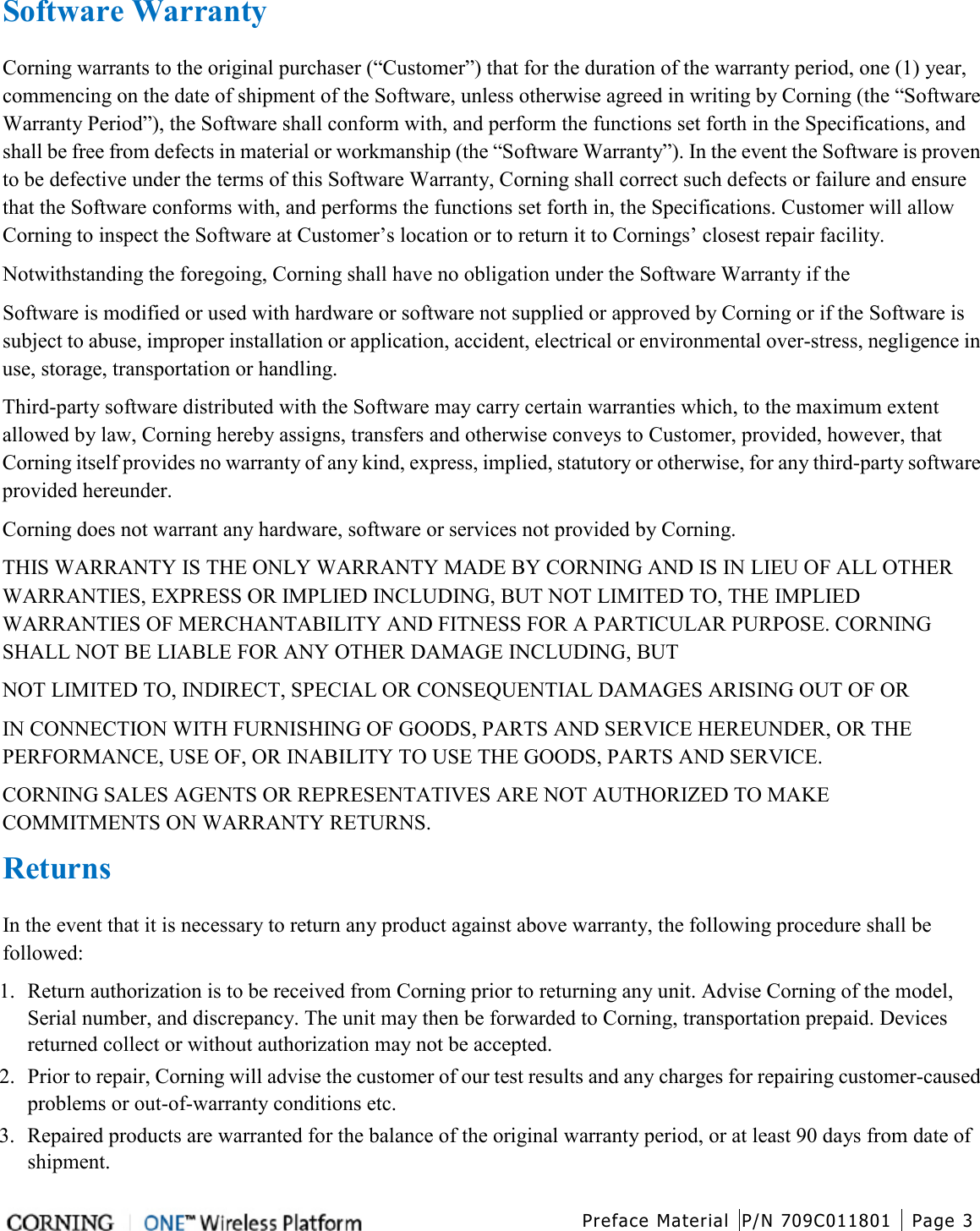
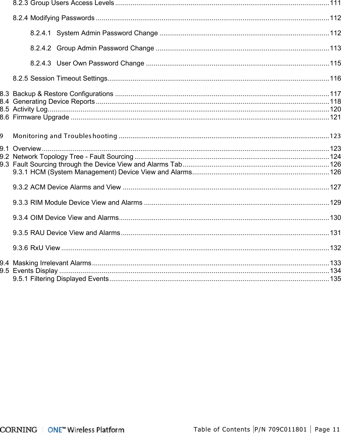
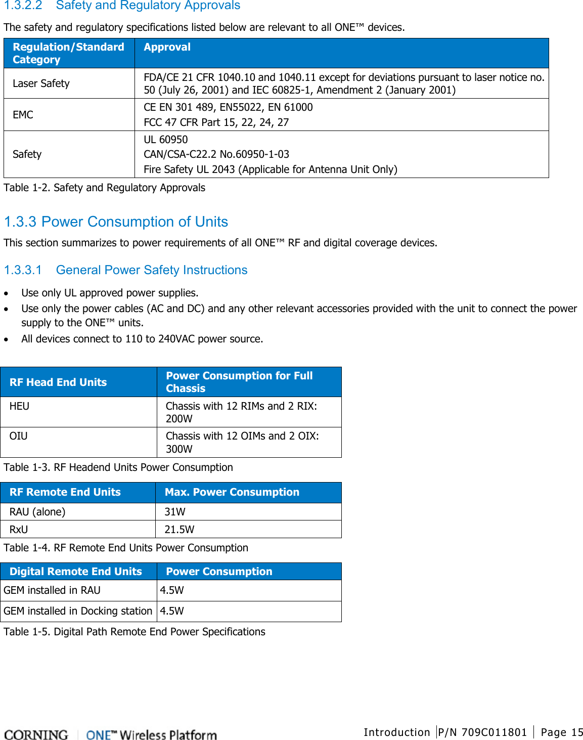
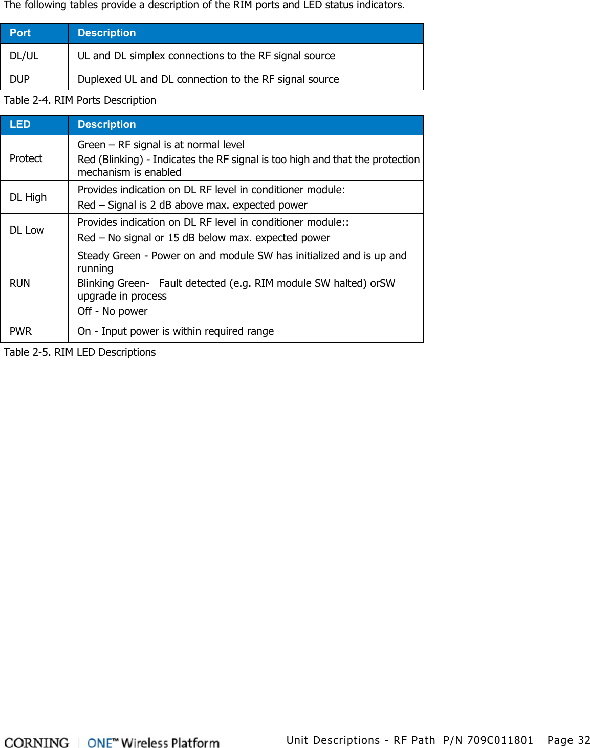
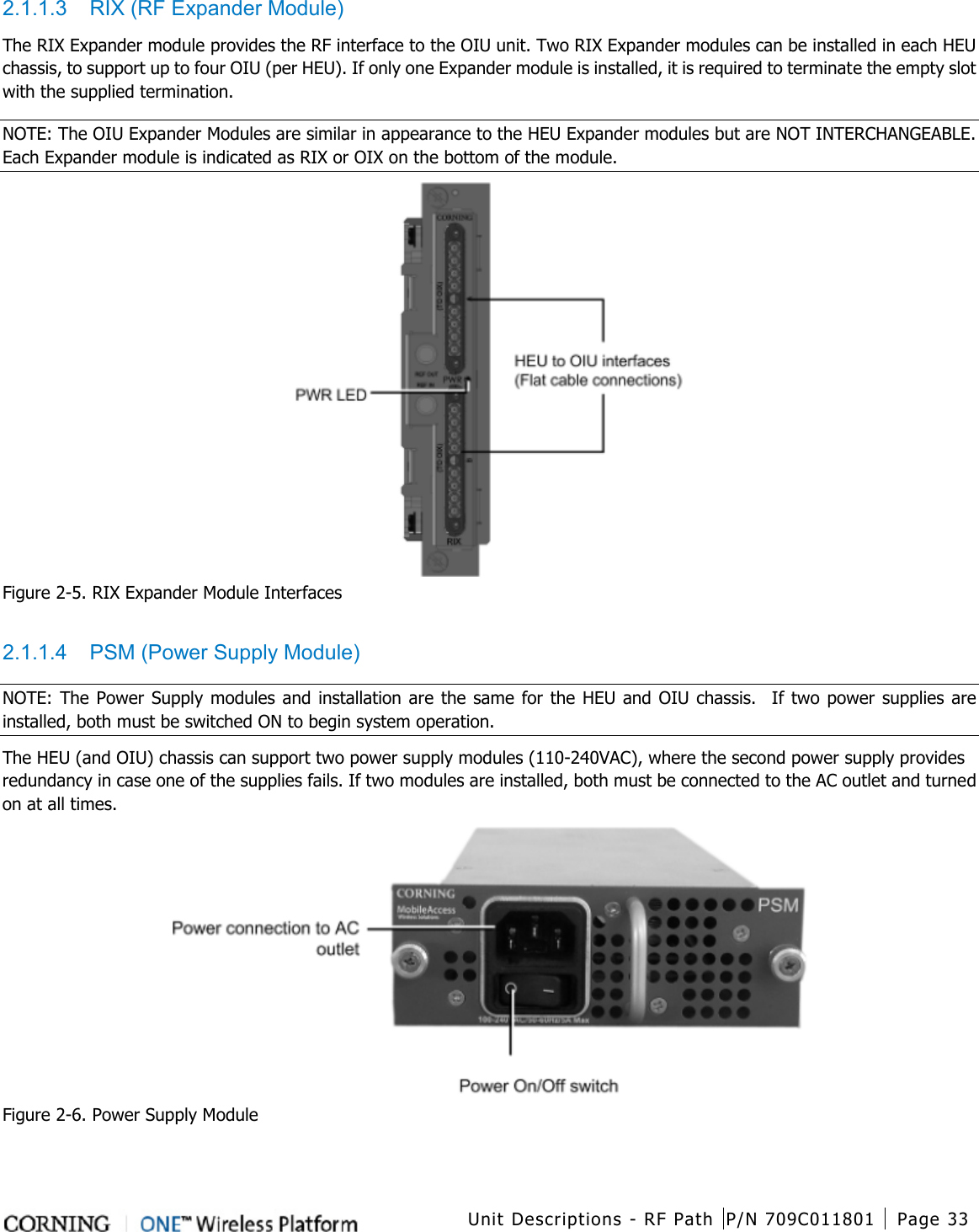
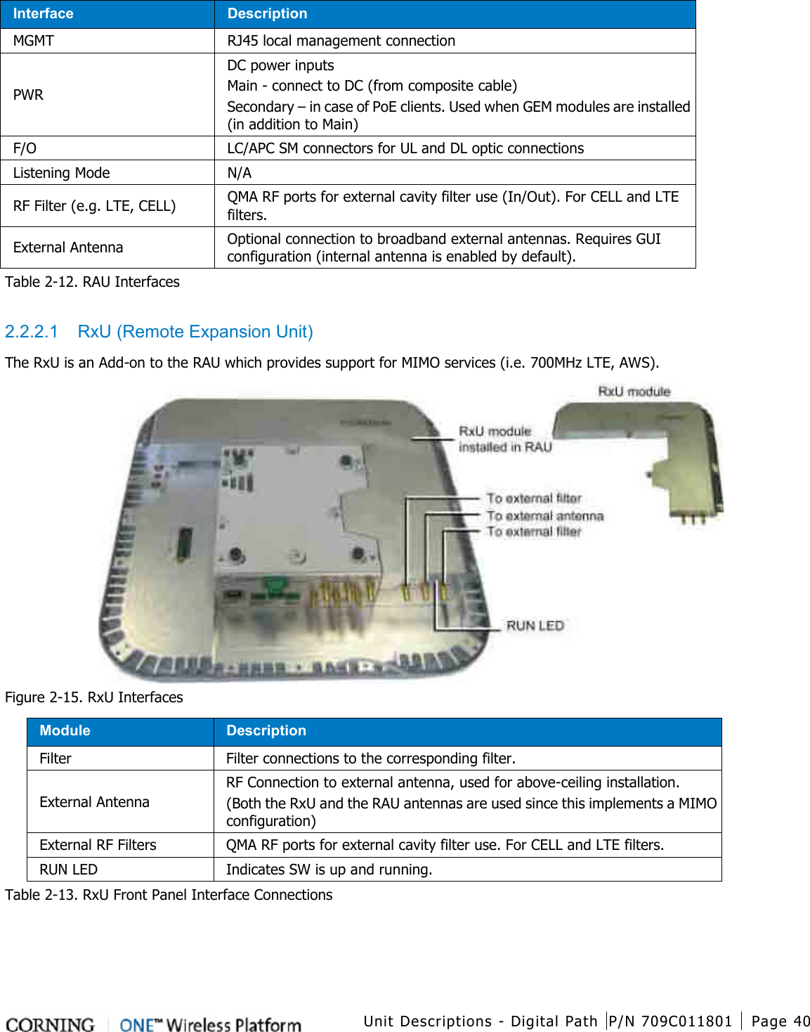
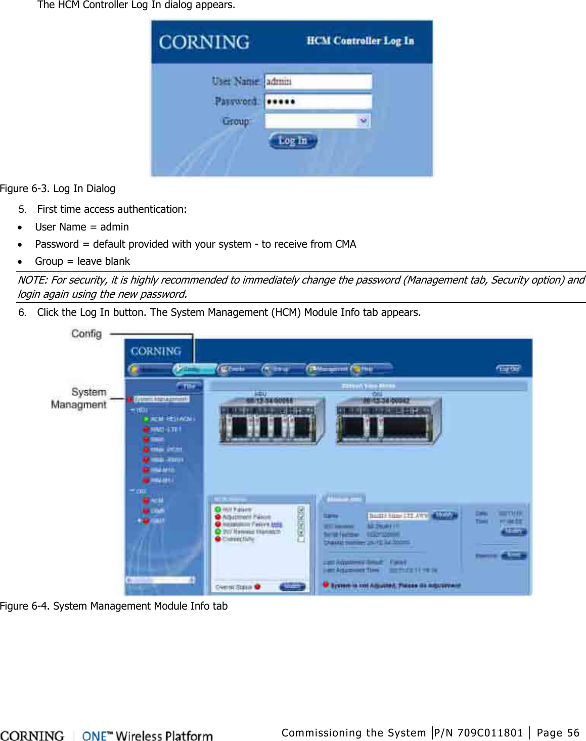
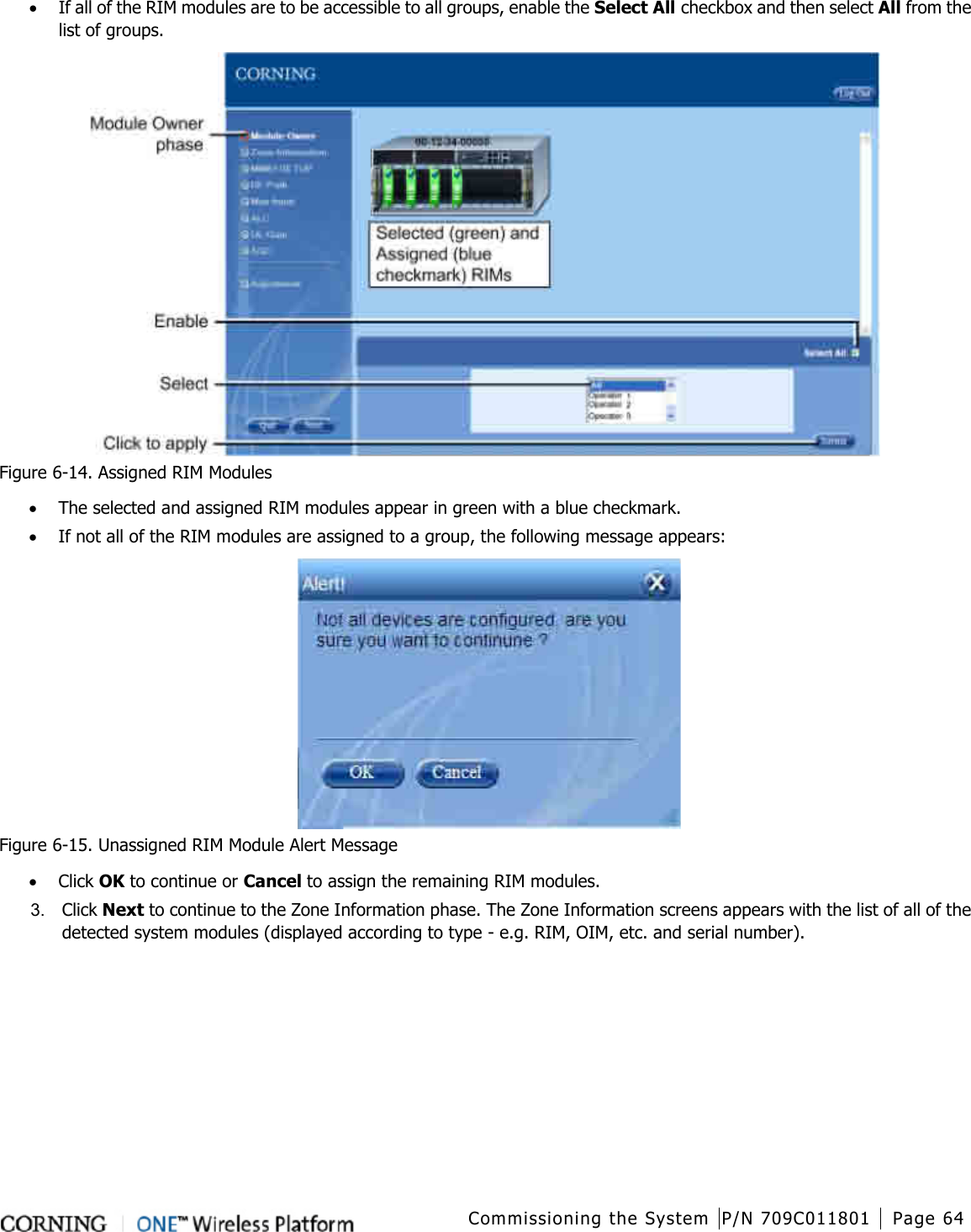
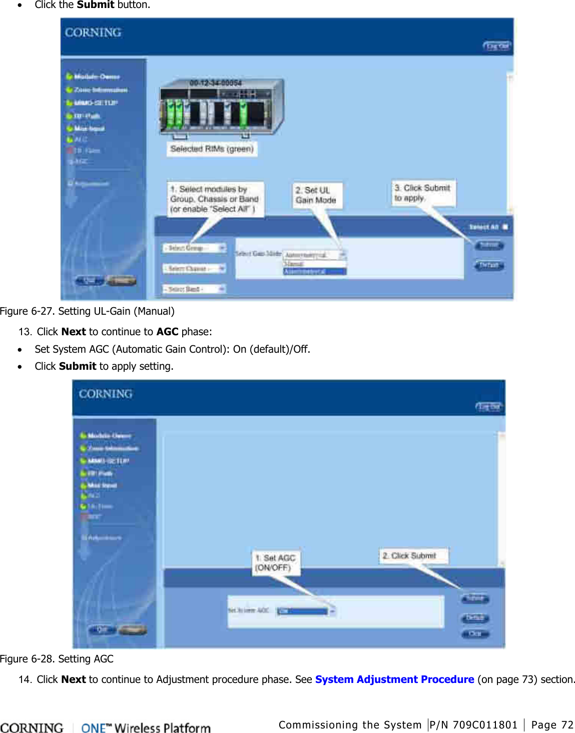
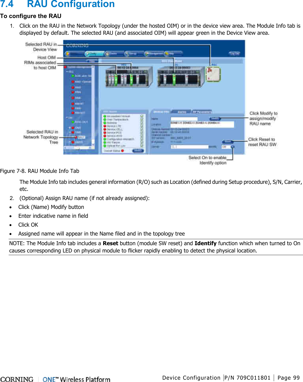
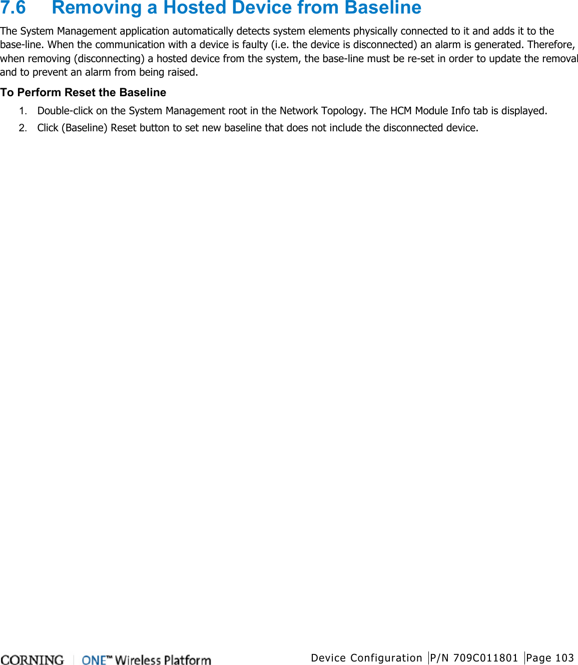
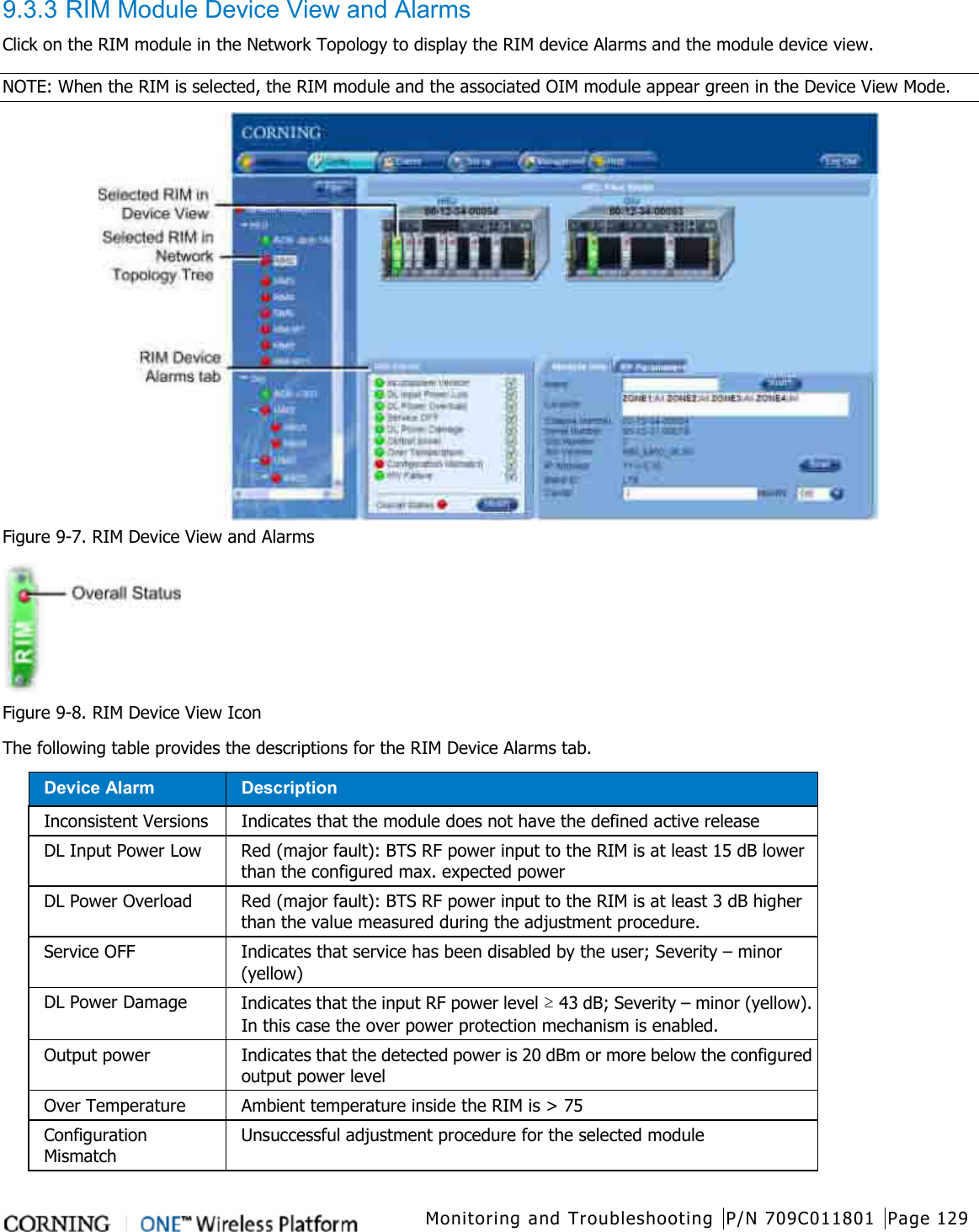
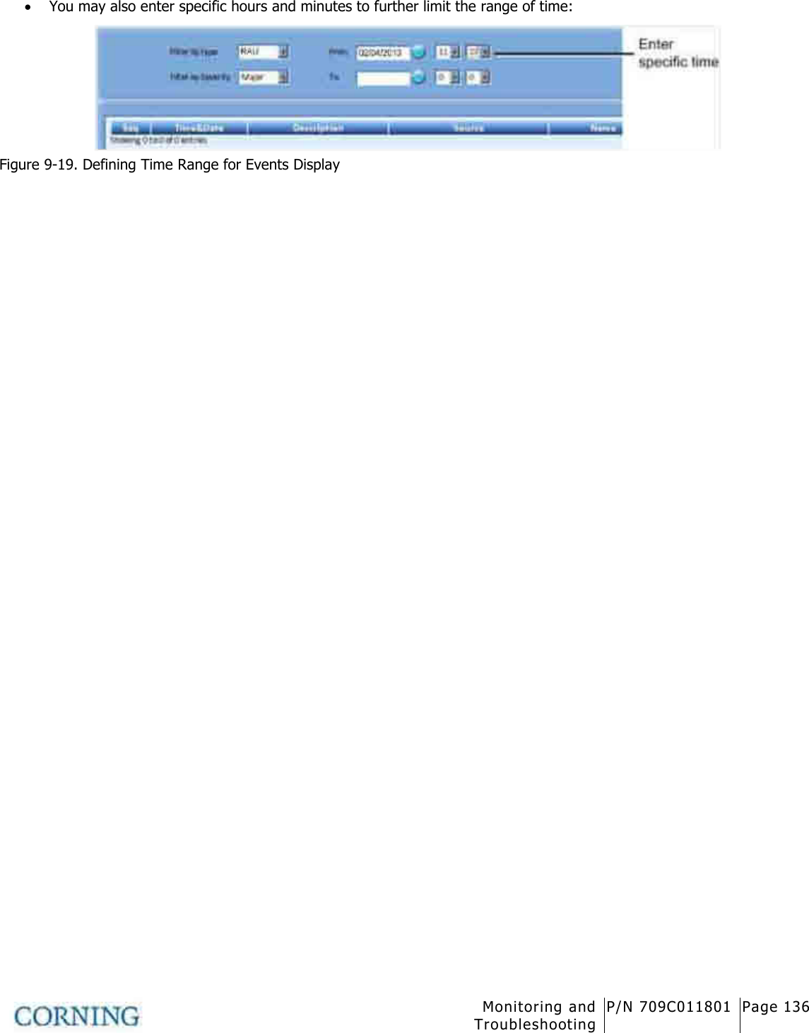
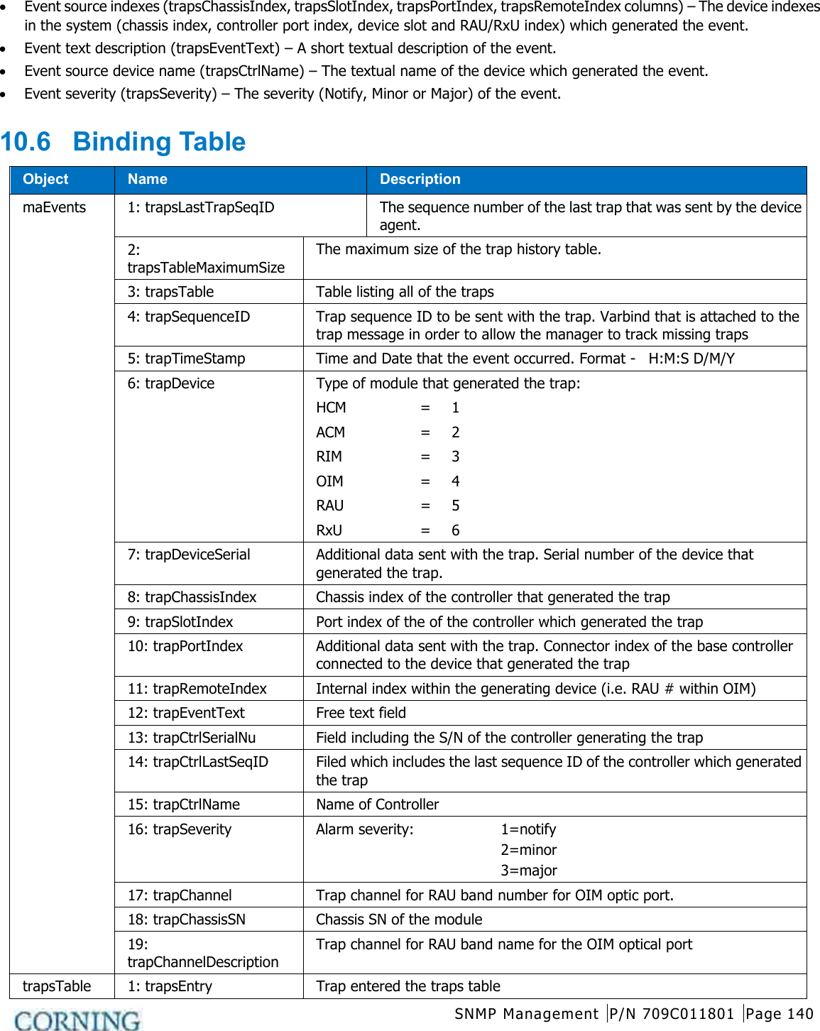
![Unit Descriptions - RF Path P/N 709C011801 Page 31 Port Description INTERNAL (TO ACM) [4] RJ45, 100Mb Ethernet ports - used for management of connected OIU systems (and/or HEU Slaves). LAN RJ45, 1Gb Ethernet port - connects to the corporate LAN for remote management LOCAL RJ45, 1Gb Ethernet port - local configuration and management CONSOLE RJ45, serial port - local configuration for service personnel SD Card Slot Supports uSD cards up to 32GB (used for example for saving configuration files) Table 2-2. HCM Ports LED Description PWR Steady Green - Power supplied to unit Off – No power is supplied to the unit RUN Steady Green – HCM Boot up sequence complete and functioning Blinking Green – HCM Boot up sequence in process Off – No power supplied to the unit SYS Indicates overall status of the managed system FAN Green – Normal operation status Red – Faulty fan (s) Table 2-3. LED Description 2.1.1.2 RIM/RIM-M (RF Interface Module) Up to 12 service specific conditioning modules are installed in the HEU chassis. Each RIM supports both Simplex and Duplex RF connectors. RIM-M modules support MIMO services (e.g.700 MHz LTE, AWS). LEDs provide status indications on signal level and module operation. Figure 2-4. RIM Module](https://usermanual.wiki/Corning-Optical-Communication-Wireless/1C85P19L70A17.User-Manual/User-Guide-2036299-Page-31.png)
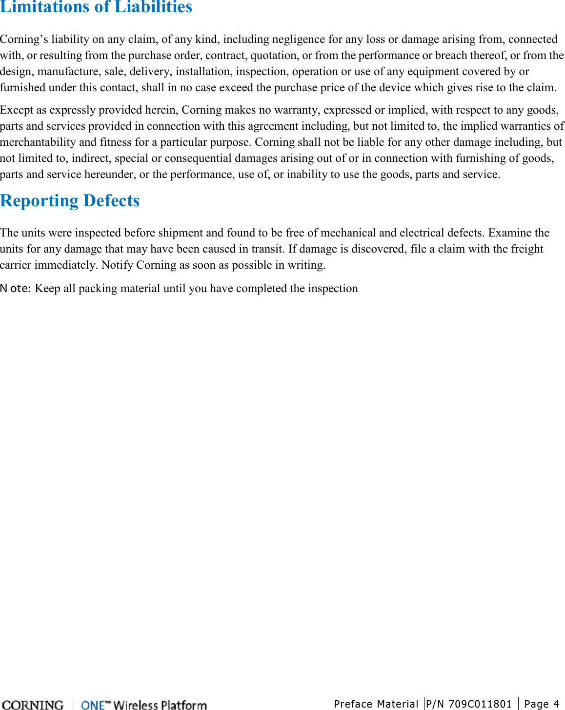
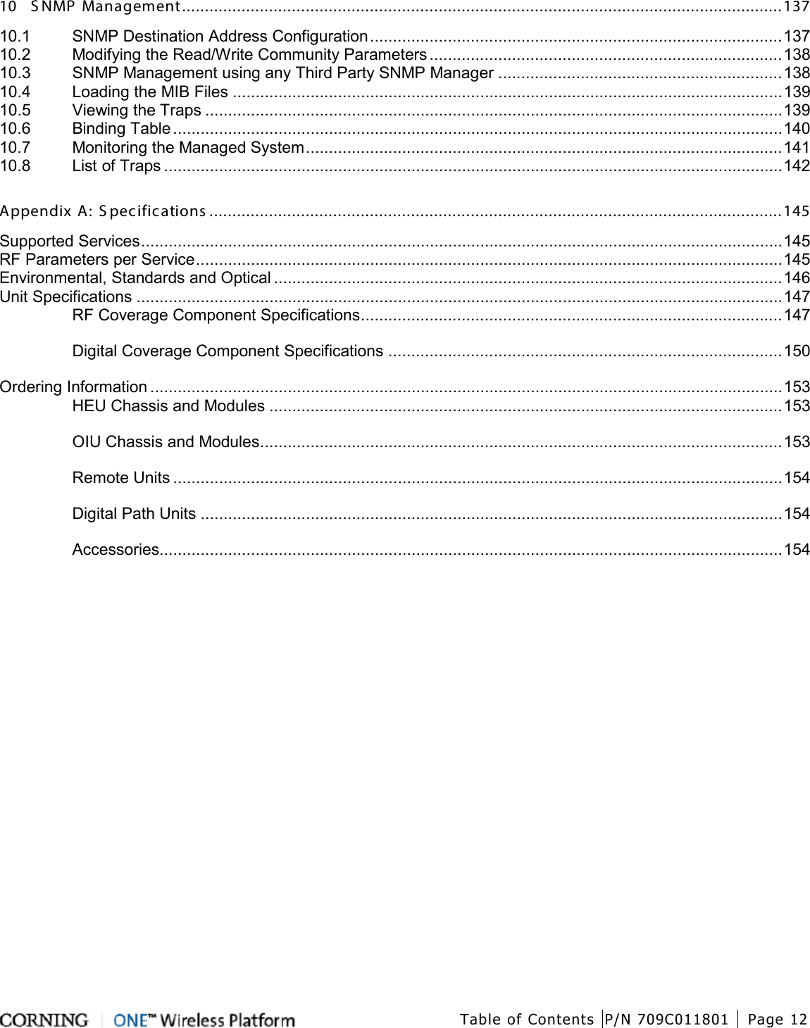
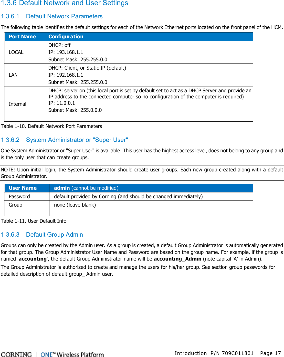
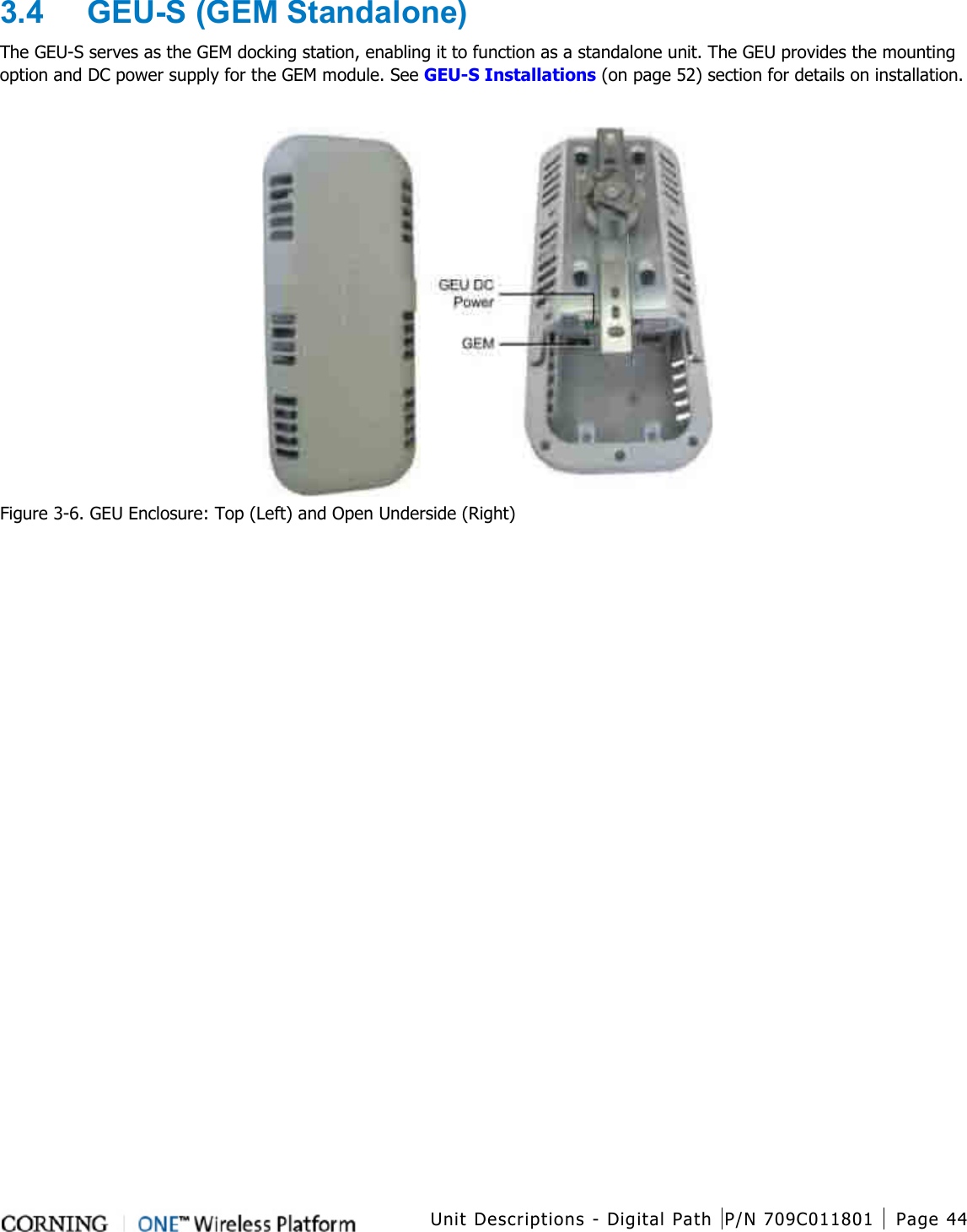
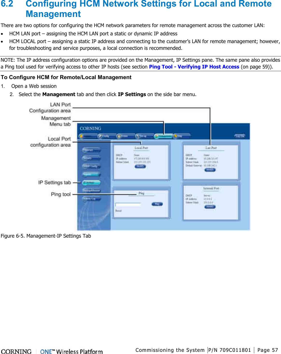
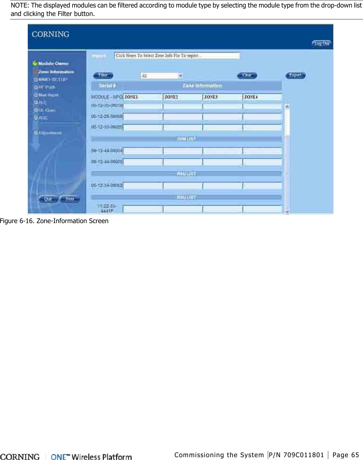
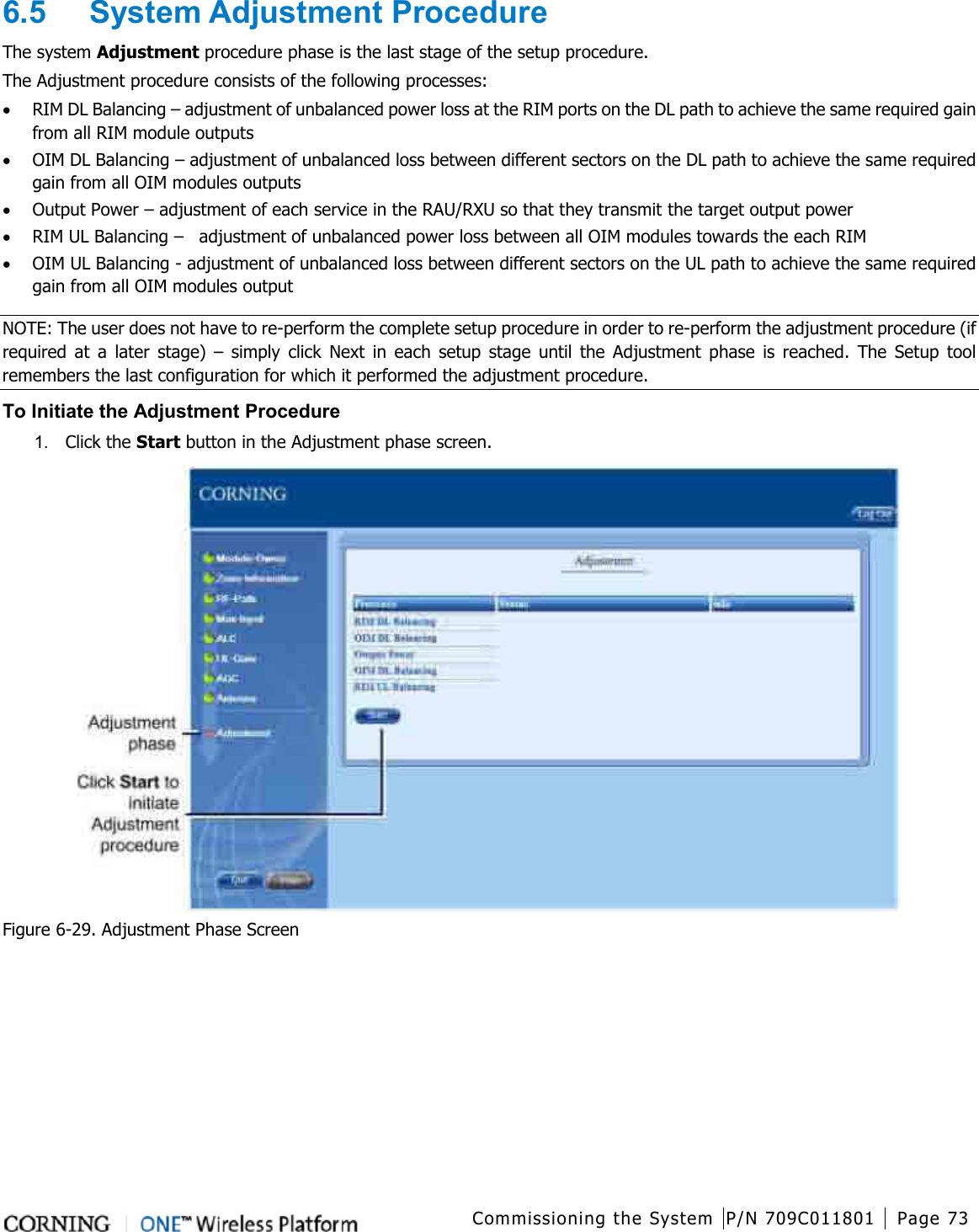
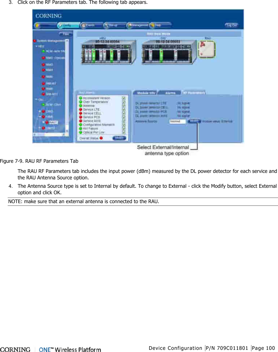
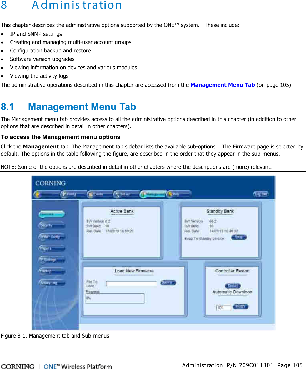
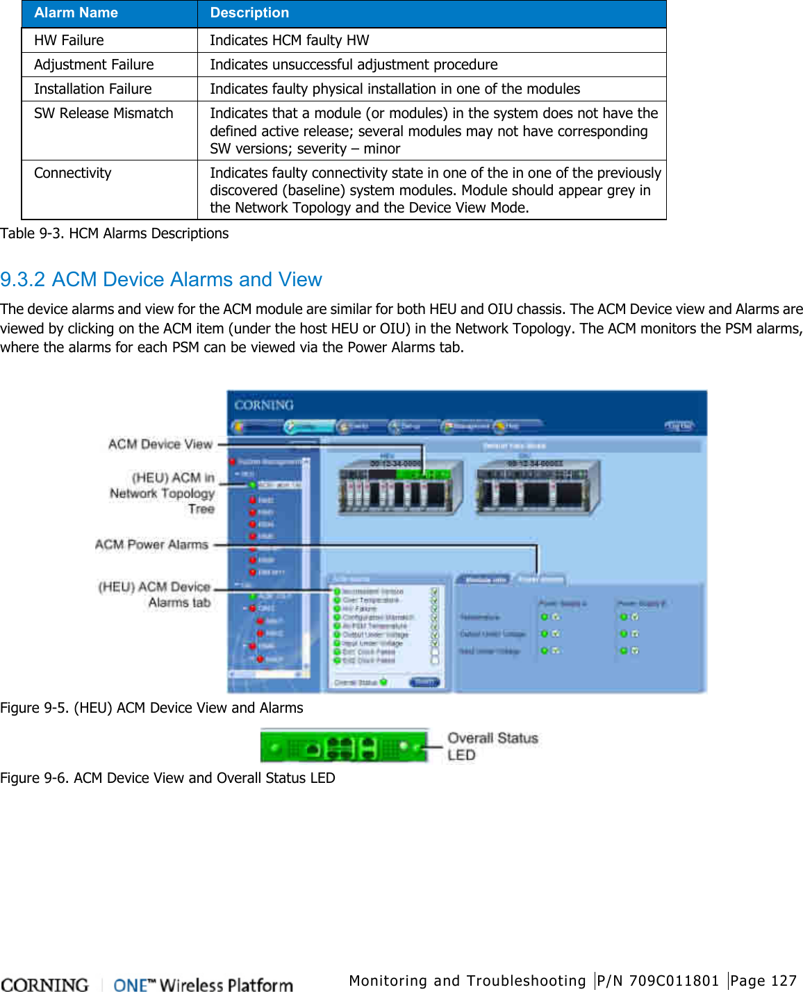
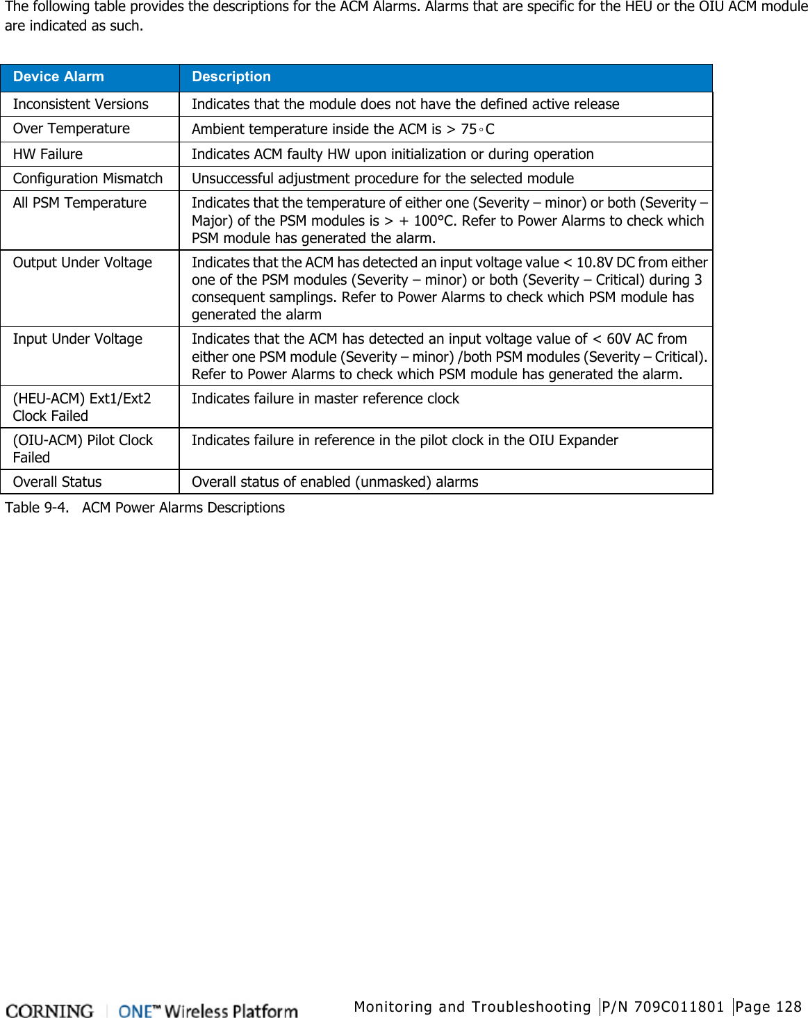
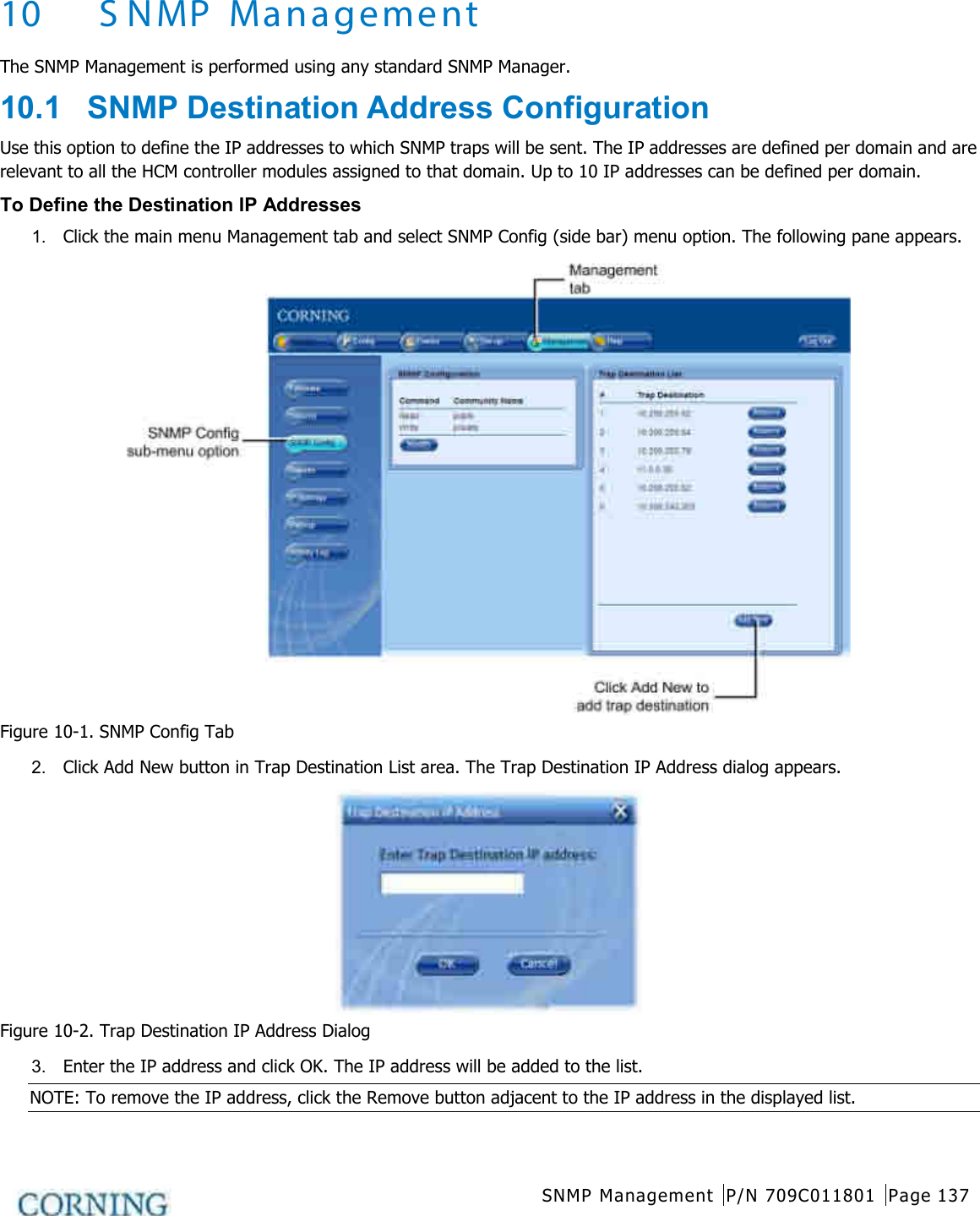
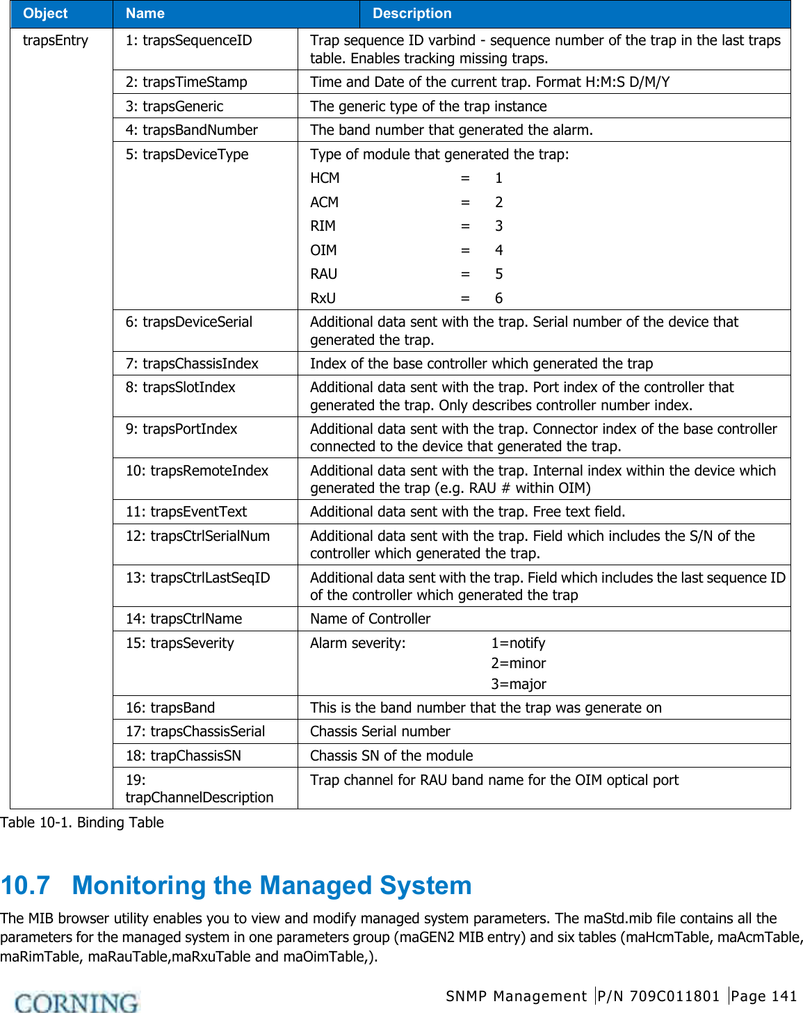
![Unit Descriptions - RF Path P/N 709C011801 Page 35 2.1.2.1 ACM (Auxiliary Control Module) The ACM provides basic control functions (only) for the host chassis via a local connection. The ACM module can be remotely managed via an HCM (on page 30) connection. Figure 2-8. ACM Module Port Description INTERNAL (TO HCM) [4] RJ45, 100Mb Ethernet ports used for OIU and/or HEU slave management connections Console [1] RJ45, serial port used for basic IP configuration and local connection for service personnel Table 2-7. ACM Ports Description LED Description PWR Steady Green - Power supplied to unit Off – No power is supplied to the unit RUN Steady Green – HCM Boot up sequence complete and functioning Blinking Green – HCM Boot up sequence in process Off – No power supplied to the unit SYS Indicates overall status of the managed system FAN Green – Normal operation status Red – Faulty fan (s) Table 2-8. ACM LED Indicators Description](https://usermanual.wiki/Corning-Optical-Communication-Wireless/1C85P19L70A17.User-Manual/User-Guide-2036299-Page-35.png)
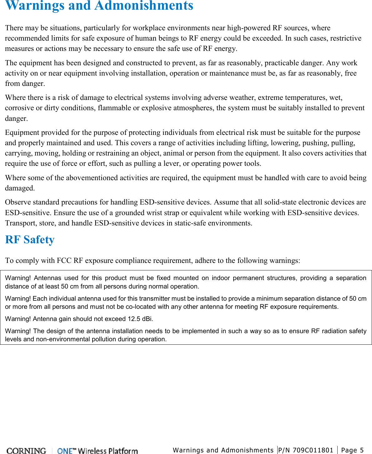
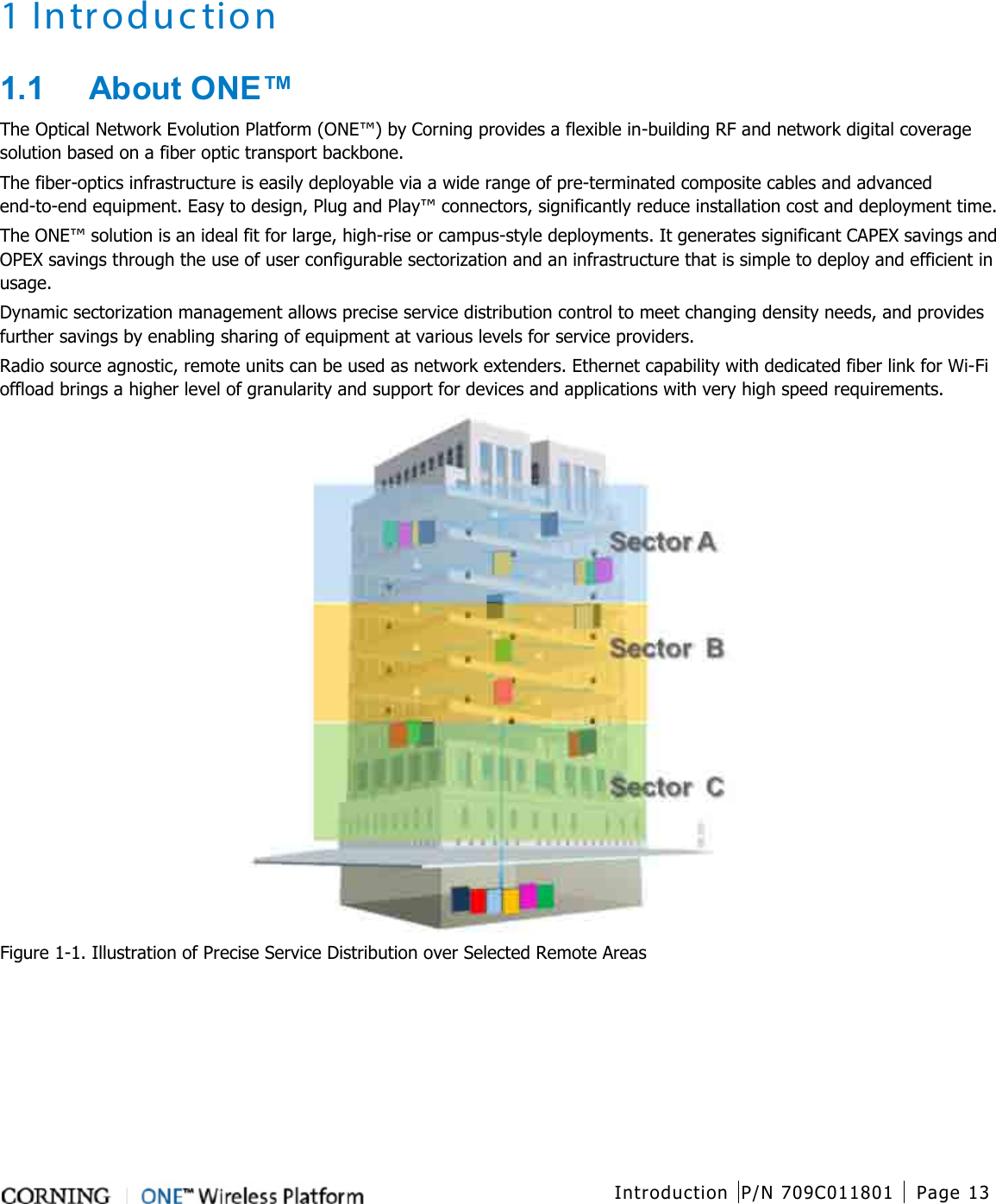
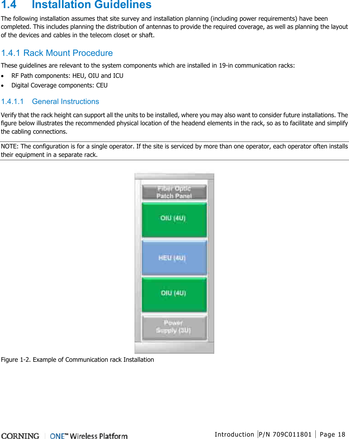
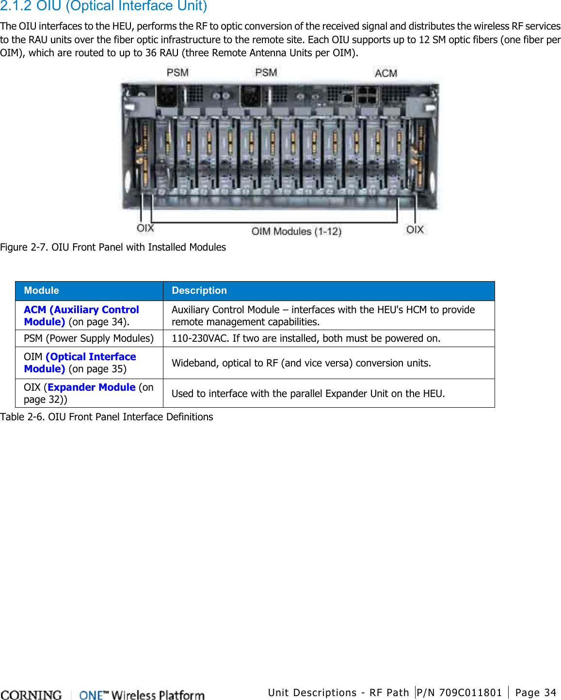
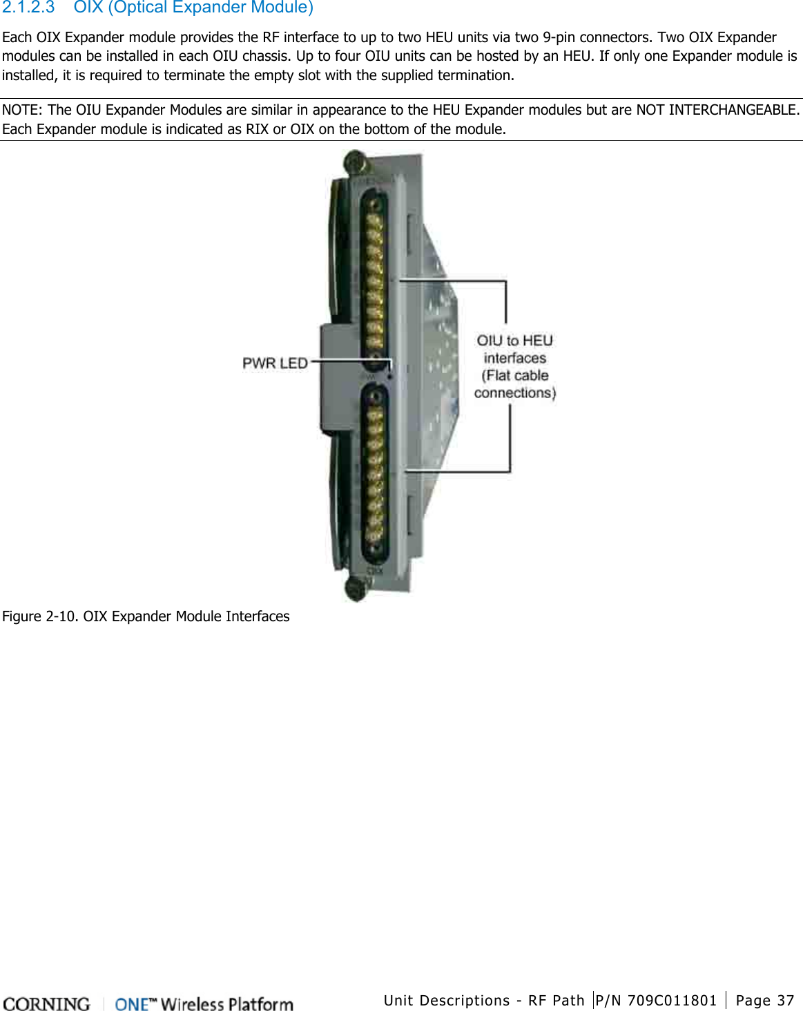
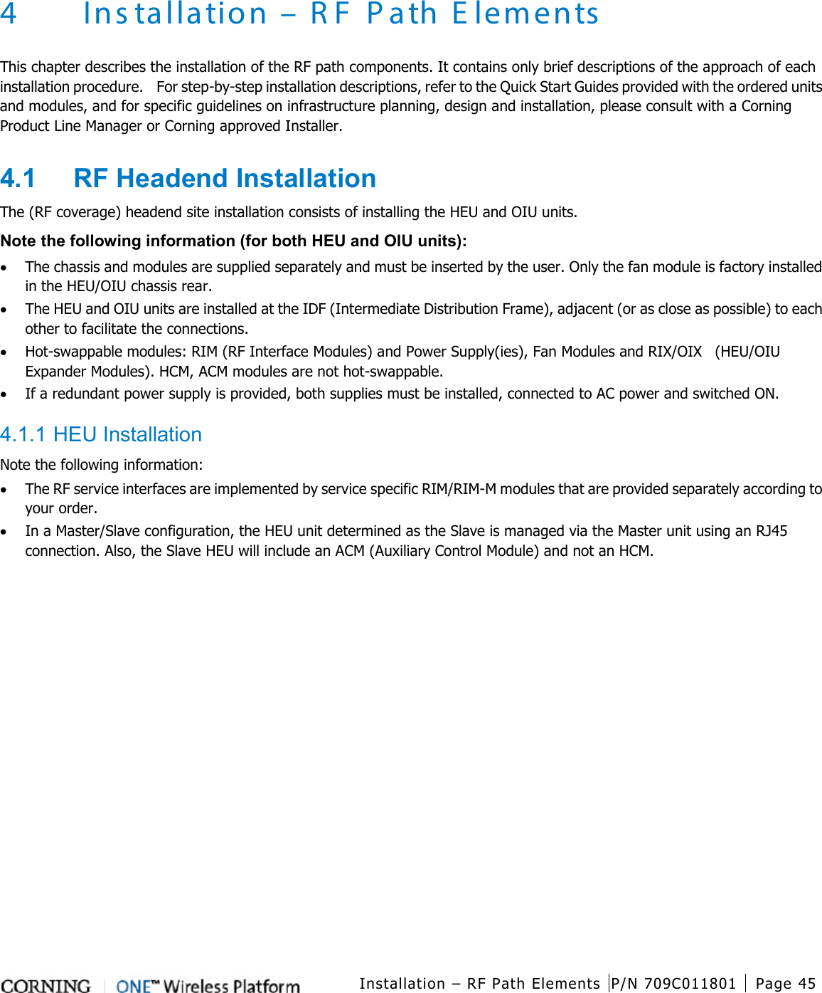
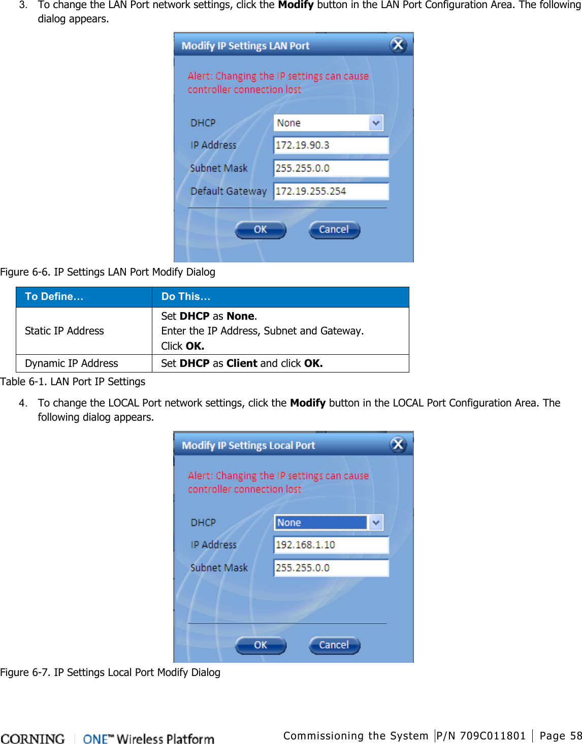
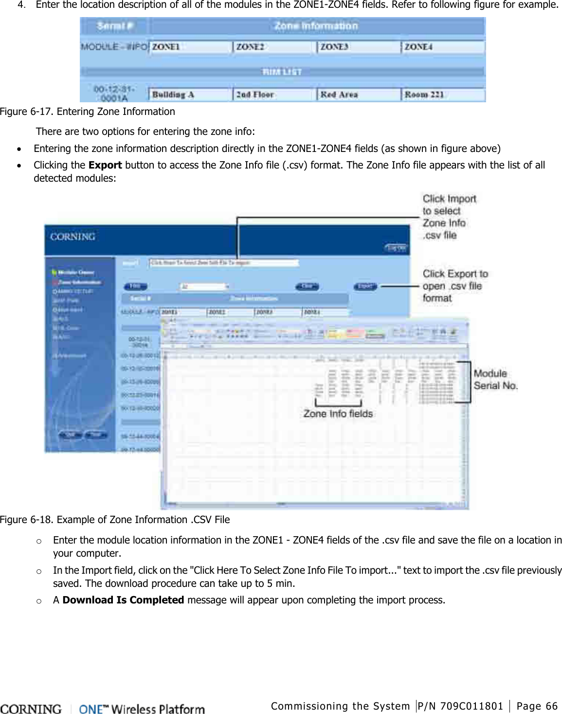
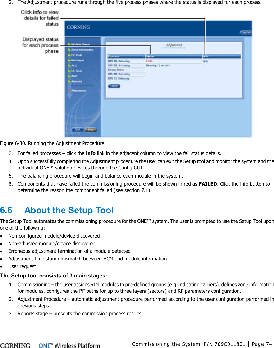
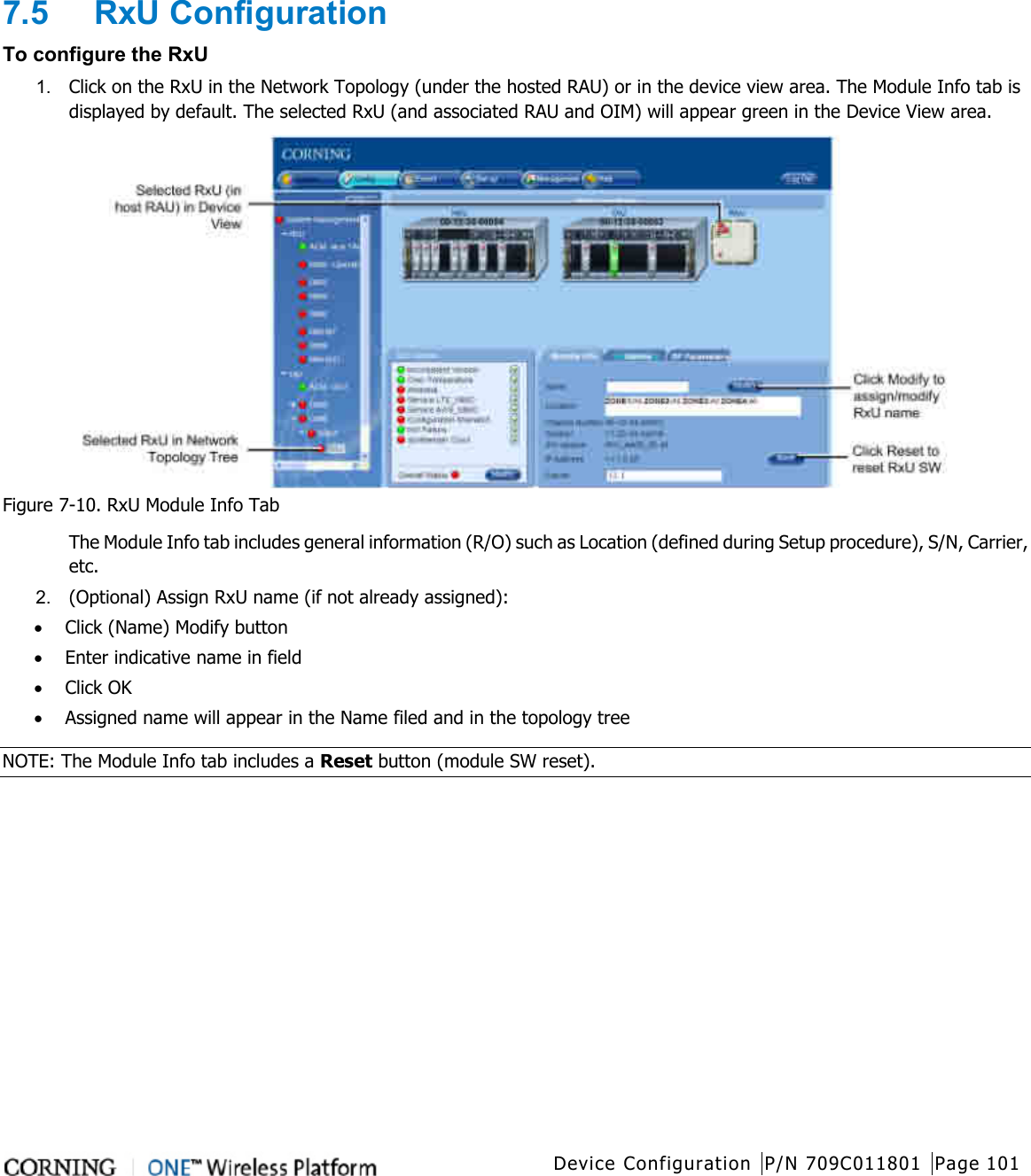
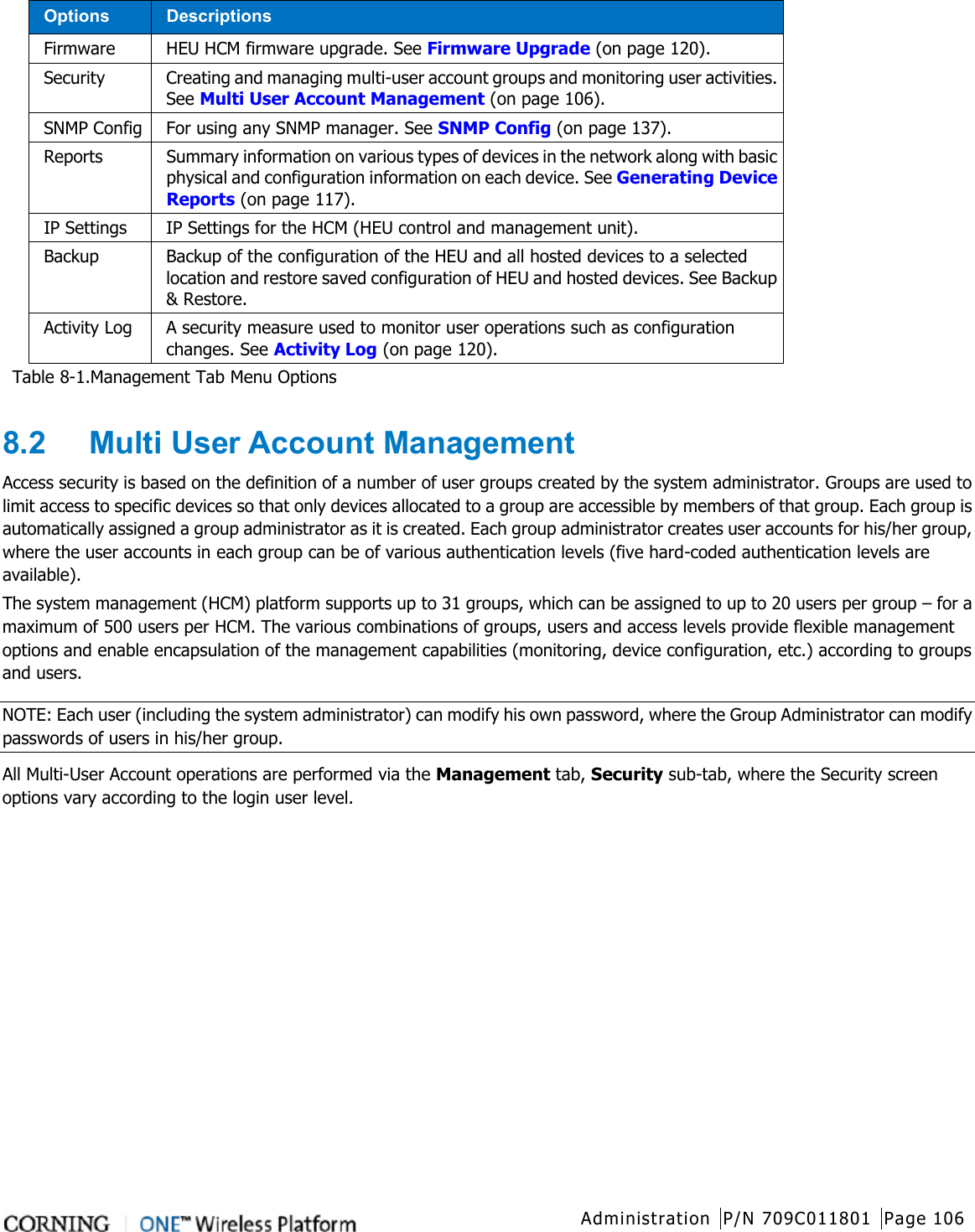
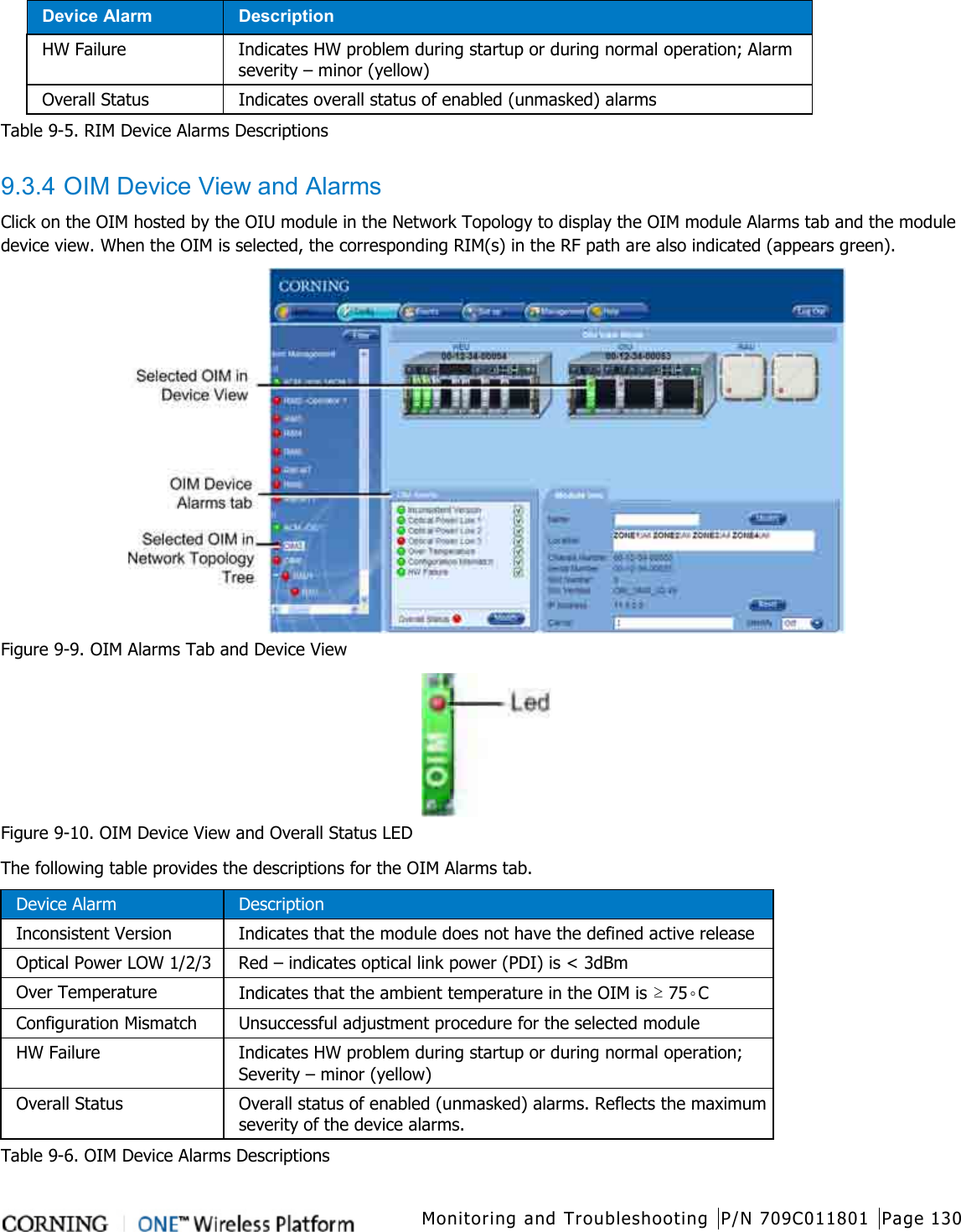
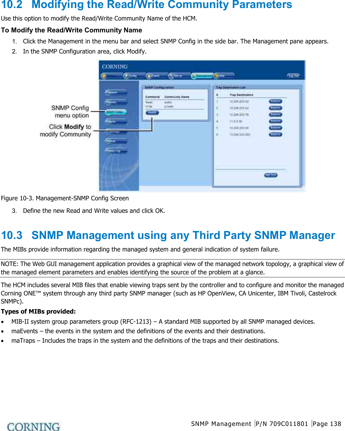
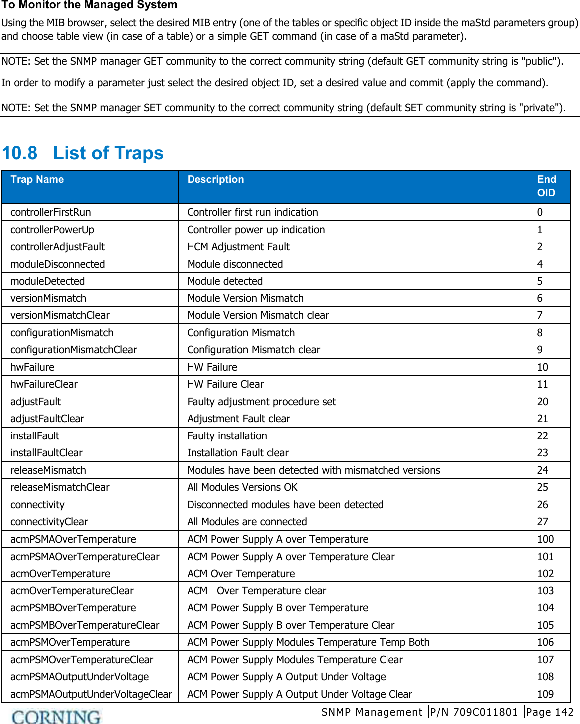
![Unit Descriptions - RF Path P/N 709C011801 Page 36 2.1.2.2 OIM (Optical Interface Module) The OIM is a wideband RF to F/O (and vice-versa) media conversion module. Up to 12 OIM units can be installed in each OIU, where each OIM can support up to three Remote Antenna Unit (RAU) connections. Figure 2-9. Optical Interface Module Port Description Optical Link MTP Connector for optical interface connection; SMF Expansion [6] Kenpole connector for 1:1 direct signal transportation, 3 UL and 3 for DL Enables (DL and UL) broad band connection to each optical link Table 2-9. OIM Ports Description LED Description Link 1-3 ON - the optical link to/from the connected remote functions within the specifications in both directions. Blinking - optical power from remote is lower than required RUN Steady Green – SW Boot up sequence complete and functioning PWR Steady Green – Power input detected for corresponding module Table 2-10. OIM LED Descriptions](https://usermanual.wiki/Corning-Optical-Communication-Wireless/1C85P19L70A17.User-Manual/User-Guide-2036299-Page-36.png)
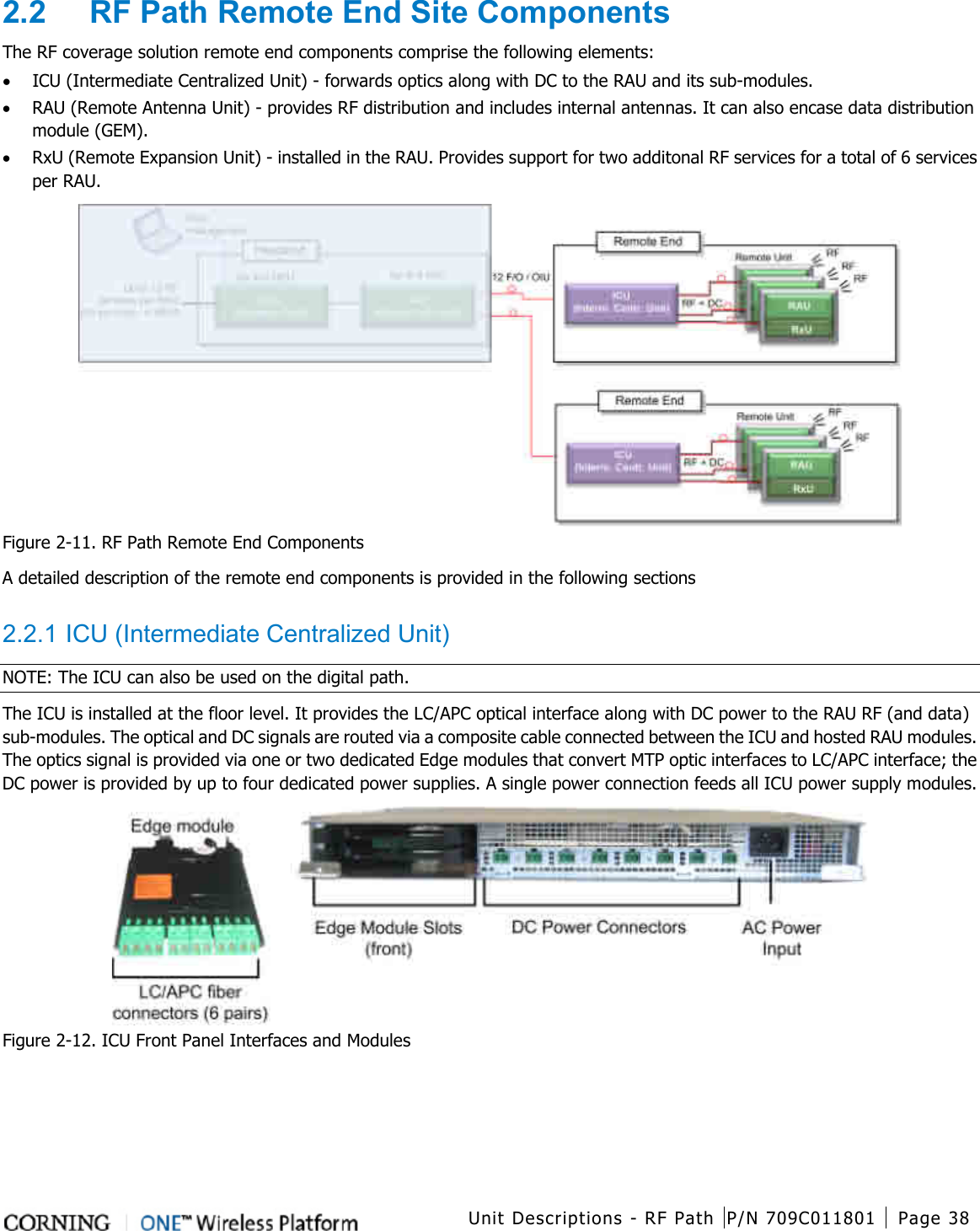
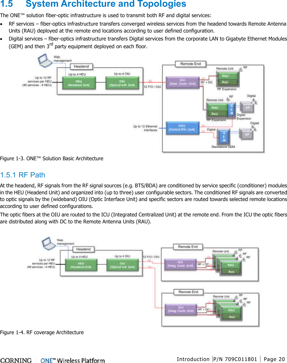
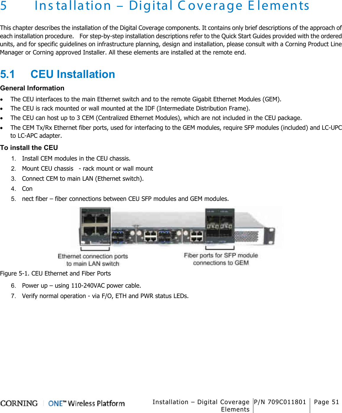
![Unit Descriptions - Digital Path P/N 709C011801 Page 41 3 Unit Descriptions - Digital Path This chapter provides detailed descriptions of the Digital Path components. 3.1 Digital Path Components The digital path comprises the following elements - located at the remote end • CEU – Centralized Ethernet Unit • GEM – Gigabit Ethernet Module - NOTE: The GEM module can be installed in two configurations: in the RAU enclosure or (as illustrated below) as a standalone unit in a Docking Station. Figure 3-1. ONE™ Digital Path Architecture 3.2 CEU (Centralized Ethernet Unit) The CEU is a Centralized Ethernet-over-Fiber Media Converter Unit. Located at the remote end, it converts Ethernet media (from a LAN switch) to fiber media for routing towards GEM modules. The CEU hosts three Centralized Media Converter Modules [CEMs]. Each module supports four Ethernet ports (LAN switch connections) and four F/O connectors (towards GEM modules). Figure 3-2. CEU Front Panel with Installed CEM Module Figure 3-3. CEU Rear Panel](https://usermanual.wiki/Corning-Optical-Communication-Wireless/1C85P19L70A17.User-Manual/User-Guide-2036299-Page-41.png)
![Unit Descriptions - Digital Path P/N 709C011801 Page 42 3.2.1 CEM (Centralized Ethernet Module) The CEU supports up to three CEM modules, where each CEM supports four Ethernet ports (LAN switch connections) and four F/O connectors (towards GEM modules). All interfaces (except for power) are located on the front panel (see section CEM). Figure 3-4. CEM Interfaces (Installed in CEU) The CEM module interfaces include Ethernet connections to the Ethernet switch, F/O connections and LED status indicators. The following table provides a description of the CEM ports. Port Description ETH Four ETH connections to LAN switch F/O [4] 10/100/1000BASE-T RJ-45 connectors to [4] LC/UPC fiber connectors (using SFP –small-form pluggable module) USB port USB serial port - service port PWR Steady Green – Power input detected for corresponding module Table 3-1. Ports Description](https://usermanual.wiki/Corning-Optical-Communication-Wireless/1C85P19L70A17.User-Manual/User-Guide-2036299-Page-42.png)
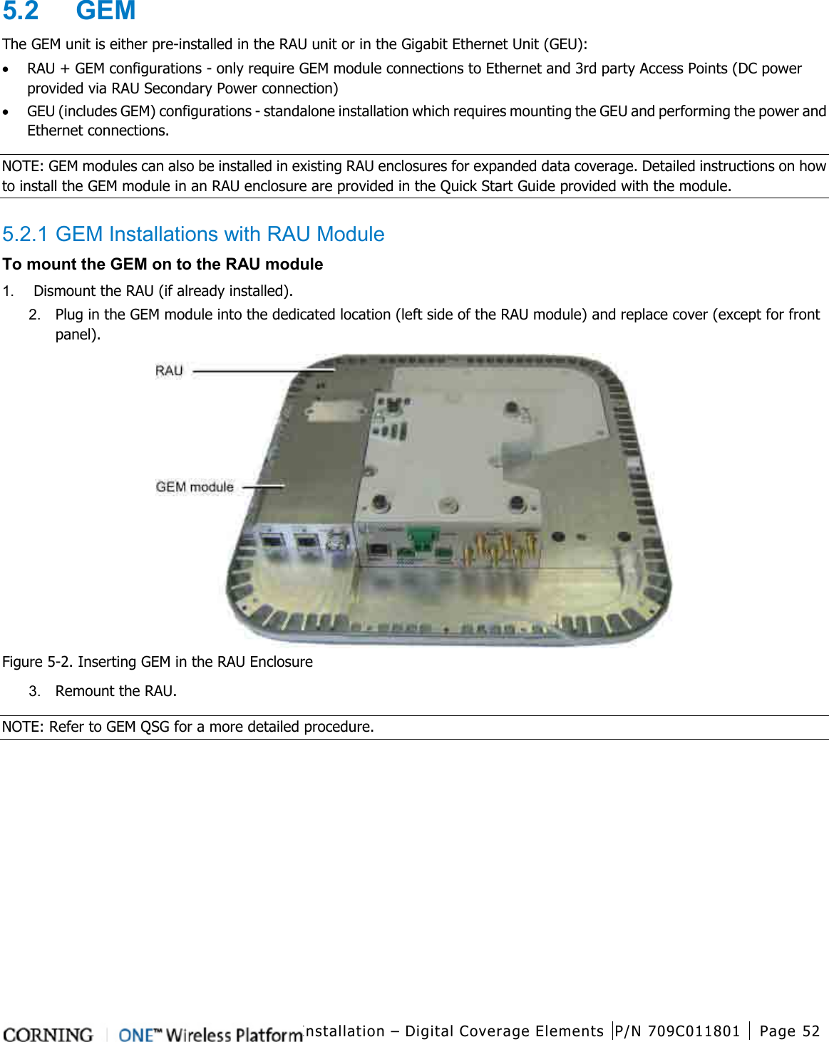
![Unit Descriptions - Digital Path P/N 709C011801 Page 43 3.3 GEM (Gigabit Ethernet Module) The GEM converts the received optical signal to two Ethernet digital connections, which are then routed along with PoE to two remote access points. The GEM module can be installed in the following configurations: • Installed in RAU - as an optional plug-in module (see RAU (on page 39)) • As a standalone module (GEU-S) - (see section GEU-S Installations (on page 52)) Figure 3-5. GEM Interfaces The following tables provide descriptions of the ports and LED indicators. Port Description PORT A/PORT B [2] RJ45 ports supporting 10/100/1000Base-T copper interface with PoE+ 802.3at PSE capability for connections to remote access points FC/APC [1] LC/UPC Fiber optic port Table 3-2. GEM Port Interfaces LED Description PoE (PORT A/PORT B) Indicates power supplied to connected AP Link ON - the optical link to/from the connected remote functions within the specifications in both directions. Blinking - optical power from remote is lower than required RUN Steady Green – GEM module SW is up and running Table 3-3. GEM LED Indicator Descriptions](https://usermanual.wiki/Corning-Optical-Communication-Wireless/1C85P19L70A17.User-Manual/User-Guide-2036299-Page-43.png)

![Appendix A: Specifications P/N 709C011801 Page 145 Appendix A: S pecifications Supported Services Technology Frequency Range (MHz) Service/Band Uplink (UL) Downlink (DL) LTE 700MHz 698-716 777-787 728-746 746-756 CDMA/WCDMA**/ TDMA/GSM/LTE* CELL800 824-849 869-894 CDMA/WCDMA**/TDMA/GSM/LTE* PCS1900 1850-1915 1930-1995 WCDMA**/LTE* AWS2100 1710-1755 2110-2155 RF Parameters per Service Service/Band LTE 700 MHz CELL 800 MHz PCS 1900 MHz AWS 2100 MHz RF Parameter DL UL DL UL DL UL DL UL Frequency Range [MHz] 728-746 746-756 698-716 777-787 869-894 824-849 1930-1995 1850-1910 2110-2155 1710-1755 Max Output Power Per Antenna Port 14 14 17 17 Max Input Power [dBm] 0 to 37 15 to 37 0 to 37 0 to 37 Mean Gain [dB] -19 to 10 -19 to 10 -19 to 10 -19 to 10 Input IP3 [dBm] AGC OFF Min -7 -7 -7 -7 Input IP3 [dBm] AGC ON Min 5 5 5 5 SFDR** [dB] 59 63 63 59 Max Intermod Distortion [dBm] -13 -13 -13 -13 UL NF*[dB] 12 12 12 12 Gain Flatness/Ripple [dB] ±2.0 ±2.0 ±2.0 ±2.0 *Typical for single remote antenna ** SFDR calculated with BW of 1.23MHz for the CELL and PCS and with 5MHz for the LTE and AWS](https://usermanual.wiki/Corning-Optical-Communication-Wireless/1C85P19L70A17.User-Manual/User-Guide-2036299-Page-145.png)
![Appendix A: Specifications P/N 709C011801 Page 146 Environmental, Standards and Optical Environmental Operating Temperature 0°C to +50°C (32°F to 122°F) Storage -20°C to 85°C (-4°F to 185°F) Standards and Approvals Laser Safety FDA/CE 21 CFR 1040.10 and 1040.11 except for deviations pursuant to laser notice no. 50 (July 26, 2001) and IEC 60825-1, Amendment 2 (January 2001) EMC CE EN 301 489, EN55022, EN 61000 FCC 47 CFR Part 15, 22, 24, 27 Safety Optical Optical Output Power <9dBm Max. Optical Budget 5 dB Optical Connector OIM: MTP connector RAU: LC/APC SM Fiber Type Corning SMF-28 or Compatible Wavelength 1310±10nm [@25 degrees C] Maximum Distance (Headend to Remote End) 2Km [SMF]](https://usermanual.wiki/Corning-Optical-Communication-Wireless/1C85P19L70A17.User-Manual/User-Guide-2036299-Page-146.png)
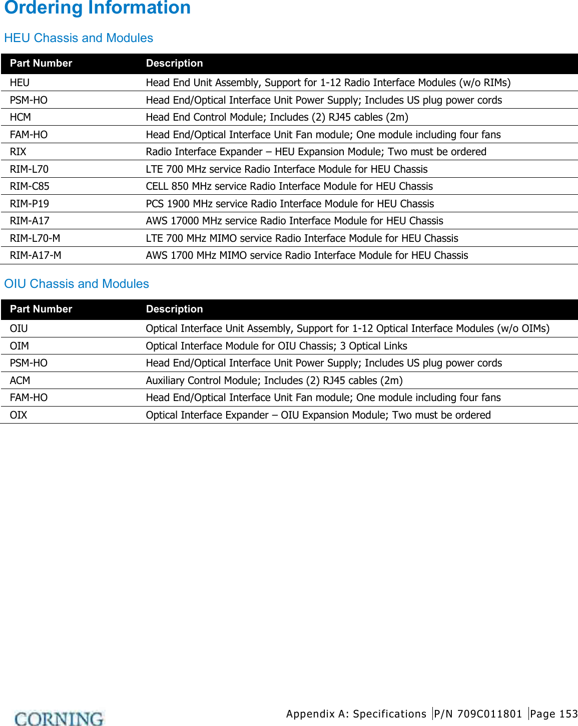
![Appendix A: Specifications P/N 709C011801 Page 147 Unit Specifications RF Coverage Component Specifications Head End Unit (HEU) HEU will host the following modules: • RIM - Radio Interface Module; RF source conditioner. Up to 12 RIMs can be hosted by the HEU. • RIX - Radio Interface Expander; HEU to OIU interface module • HCM - Headend Control Module; Overall system management module • PSM - Power Supply Module; AC Power Supply RIM Interfaces [3] QMA RF ports; UL, DL and Duplex RIX Interfaces [2] 9-pin connectors [ one per OIX] HCM Interfaces [HEU Control Module] ACM Interfaces: [4] RJ45 INTERNAL ports Remote management: [1] RJ45 LAN port Local Management: [1] RJ45 LOCAL port Local Configuration: [1] CONSOLE port System LEDs – PWR, RUN, SYS, FAN PSM Input: AC 100-220v Power Consumption [Full Chassis]: 200W ON/Off Switch Optional: Additional PSM for redundancy Physical Characteristics [Chassis] Rackmount - 19" and 4U Dimensions [H x W X D] US [International]: 7 x 17.3 x 18.95 in [177.8 x 440 x 481.7 mm] Weight lbs [kg]: Chassis: 37 lbs [16.8 kg] Per RIM: 1.9 lbs [0.9 kg] Per RIX: 1.54 lbs [0.7 kg] HCM: 2.2 lbs [1.0 kg] PSM: 1.98 lbs [0.9 kg] Optical Interface Unit [OIU] OIU will host the following modules: • OIM - Optical Interface Modules; Converts the RF to 3 optical links • OIX - Optical Interface Expander; OIU to HEU interface module • ACM - Auxiliary Control Module; Manages unit domestic modules, "Slave" controller to the HCM • PSM - Power Supply Module; Powers the unit • ERFC85 - RF interface cable, 9-PIN 85 cm](https://usermanual.wiki/Corning-Optical-Communication-Wireless/1C85P19L70A17.User-Manual/User-Guide-2036299-Page-147.png)
![Appendix A: Specifications P/N 709C011801 Page 148 OIM Interfaces Optical Interface: [1] MTP Connector [6] Kenpole connector for 1:1 direct signal transportation, 3 UL and 3 for DL OIX Interfaces RF Interface – [2] 9-pin connectors ACM Interfaces [4] RJ45 INTERNAL ports [1] RJ-45 CONSOLE port System LEDs – PWR, RUN, SYS, FAN PSM (See PSM in HEU section for interfaces) Power Consumption [Full Chassis]: 300W Physical Characteristics [Chassis] Mounting: Rackmount - 19" and 4U Dimensions [H x W X D] US [International]: Chassis: 7 x 17.3 x 18.95 in [177.8 x 440 x 481.7 mm] Cable Management tray: 6.96 x 20.02 x 4.35 in [176.9 x 508.6 x 110.6 mm] Weight lbs [kg]: Chassis : 37 lbs [16.8 kg] Per OIM:1.5 lbs [0.7 kg] Per OIX: 1.54 lbs [0.7 kg] ACM: 2.2 lbs [1.0 kg] PSM: 1.98 lbs [0.9 kg]](https://usermanual.wiki/Corning-Optical-Communication-Wireless/1C85P19L70A17.User-Manual/User-Guide-2036299-Page-148.png)
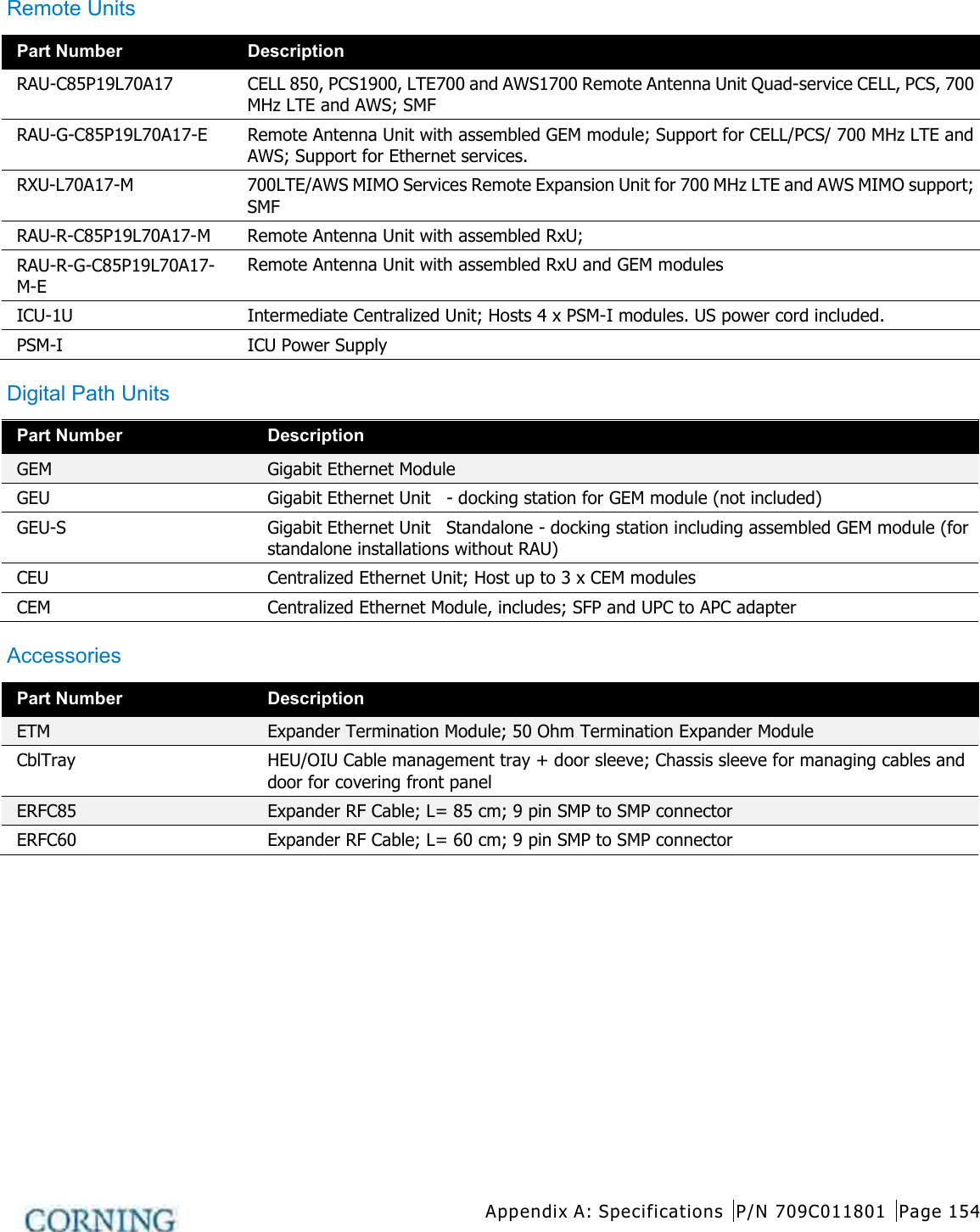
![Appendix A: Specifications P/N 709C011801 Page 149 Intermediate Centralized Unit [ICU] Chassis Interfaces Power Input: 110-240V AC, 50-60 Hz power Output: [8] DC ports- 57V DC, Max. 60V [UL limit] Edge Module Interfaces [1] MTP SM fiber port to [6] LC/APC SM Physical Characteristics Mounting: Rackmount - 19" 1U Dimensions [HxWxD]: US [International] 17 x 15 x 19.2 in [430.5 x 379.8 x 488 mm] Weight lbs [kg]: 5.5 lbs [2.5 kg] – without PSM Remote Antenna Unit [RAU] Supported Services SISO: CELL, PCS, AWS, 700LTE MIMO: AWS/ 700LTE (with Expansion Module - RxU) Interface Connections [2] LC/APC SM fiber connectors; UL and DL [2] DC power Inputs ports; Main and secondary incase of PoE clients. [2] QMA RF Ports; for External cavity filter (In/Out) use LTE and CELL filters [1] External antenna [1] RJ45 MGMT [local] connection RxU module interface – Power, Digital and RF GEM module Interface – Power and Digital Antenna Omni Directional; 0dBi (15 Deg down from horizon) Broadband External antenna QMA Connector Management Managed via the HCM Physical Characteristics Mounting: Horizontal mount above or below Acoustic Ceiling Dimensions [H x W X D] US [International]: 13.1 x 13.1 x 4 in (including mounting bracket) [332.7 x 332.7 x 101.6 mm] Weight lbs [kg]: RAU only: 7.93 lbs [3.6 kg] RAU + RXU + GEM: 12.12 lbs [5.5 kg] Environment Ambient Temperature: Wall-mount installations: 45◦C [113◦F] Ceiling-mount installations: 50◦C [122◦F] *Mounting below acoustic ceiling requires the appropriate support bracket (not supplied). **Second connection used when a GEM module is installed](https://usermanual.wiki/Corning-Optical-Communication-Wireless/1C85P19L70A17.User-Manual/User-Guide-2036299-Page-149.png)
![Appendix A: Specifications P/N 709C011801 Page 150 Remote Expansion Unit (RxU) Services Add-on unit supporting two service AWS MIMO and LTE700) MIMO Interfaces [3] pins for integration with RAU [power, control and RF] Management Management via host RAU Physical Characteristics Mounting: Installed in the RAU enclosure Dimensions [H x W X D] US [International]: 1.09 x 12.8 x 9.8 in [27.7 x 327.5 x 250 mm] Weight lbs [kg]: 3.08 lbs [1.4 kg] Digital Coverage Component Specifications Centralized Ethernet Unit (CEU) Services Centralized Media Converter Unit Ethernet over Fiber Hosts Three Media Converter Modules [CEMs] CEM Interfaces [Centralized Ethernet Module] CEM supports [4] 10/100/1000BASE-T RJ-45 connectors to [4] LC/UPC fiber connectors [4] 10/100/1000BASE-T Copper ports [4] 1000BASE-X fiber [1] USB serial port – service port Power Input: 110-240vac, 50-60 Hz power Physical Characteristics Mounting: Rackmount 19-in; 1U](https://usermanual.wiki/Corning-Optical-Communication-Wireless/1C85P19L70A17.User-Manual/User-Guide-2036299-Page-150.png)
![Appendix A: Specifications P/N 709C011801 Page 151 Gigabit Ethernet Module/Unit [GEM]/GEU] Services GEM – Media converter, Ethernet over fiber to Copper. 10/100/1000BASE-T Ethernet 1000BASE-X fiber. [2] 802.3at compliant Power over Ethernet [PoE] PSE ports Interfaces [1] LC/UPC Fiber optic port [2] RJ45 ports supporting 10/100/1000BASE-T copper interface with PoE + 802.3at PSE capability Physical Characteristics Mounting: Standalone: GEU Add-on: RAU Upgrade Module Dimensions [HxWxD] US [International]: 1.28 x 3.79 x 5.95 in [32.7 x 96.3 x 151.3 mm] Weight lbs [kg]: 1.1 lbs [0.5 kg] Gigabit Ethernet Unit [GEU-S] GEU-S will host the following module: GEM; Gigabit Ethernet Module; Media converter, Ethernet over fiber to Copper. Services Supplies power and management port for hosted modules. When it hosts a GEM it allows it to perform media conversion services from Fiber to Copper and to supply PoE+ PSE services Interfaces DC PWR connector Service Port – RJ45 (to GEM) Physical Characteristics Mounting: Wall/Ceiling mount Dimensions [HxWxD] US [International]: 5.01 x 10.51 x 3.26 in (including mounting bracket) [127.5 x 267 x 83 mm] Weight lbs [kg]: 2.64 lbs [1.2 kg]](https://usermanual.wiki/Corning-Optical-Communication-Wireless/1C85P19L70A17.User-Manual/User-Guide-2036299-Page-151.png)