Corning Optical Communication Wireless 1C85P19L70A17 OPTICAL NETWORK EVOLUTION DAS User Manual ONE Wireless Platform
Corning Optical Communication Wireless OPTICAL NETWORK EVOLUTION DAS ONE Wireless Platform
Contents
- 1. User Manual
- 2. Users Manual
Users Manual

FEBRUARY 2014
DRAFT
Corning
ONE™ Wireless Platform
User Manual

Preface Material P/N 709C011801 Page 2
DRAFT
Preface Material
About This Manual
This user guide provides all the information necessary to understand the architecture and general installation procedures and
requirements of Corning® ONE™ Wireless Platform.
Note: The commissioning procedure, monitoring and management capabilities and configuration options of the ONE™
Wireless Platform elements are described in a dedicated User Manual (ONE™ HCM User Manual).
Hardware
Corning warrants to the original purchaser (“Customer”) that for the duration of the warranty period, one (1) year, commencing
on the date of shipment of the Hardware, unless otherwise agreed in writing by Corning (the “Hardware Warranty Period”), the
Hardware furnished by Corning shall be free in all material respects from defects in material and workmanship, and shall
conform to the applicable portions of the Specifications, as defined below (the “Hardware Warranty”).
If notified by Customer of any such defects in material or workmanship or nonconformity with applicable portions of the
Specifications within the Hardware Warranty Period, Corning shall promptly, at its own election and expense, repair or replace
any such Hardware proven to be defective under the terms of this Hardware Warranty.
Such repair or replacement shall be Customer’s sole remedy and Corning sole obligation in the event this Hardware Warranty is
invoked. If any components comprising a part of the Hardware are replaced or repaired during the Hardware Warranty Period,
the Hardware Warranty Period for such repaired or replaced components shall extend to the longer of (i) the balance of the
Hardware Warranty Period or (ii) three (3) months from the date of repair or replacement. For purposes of this Warranty,
“Specifications” shall mean the specifications and performance standards of the Products as set forth in documents published
by Corning and delivered to Customer which contain technical specifications or performance standards for the Products.
If Customer invokes this Hardware Warranty, it shall notify Corning promptly of the claimed defect.
Customer will allow Corning to inspect the Hardware at Customer’s location, or to return the Hardware to Corning closest repair
facility. For Hardware returned to Corning repair facility, Customer shall be responsible for payment of all transportation and
freight costs (including insurance) to Cornings’ repair facility, and Corning shall be responsible for all transportation and freight
costs (including insurance) incurred in connection with the shipment of such Hardware to other repair facilities of Corning and/or
its return to Customer.
Notwithstanding the foregoing, in no event will Corning be liable for damage to Products resulting from improper handling during
or after shipment, misuse, neglect, improper installation, operation or repair (other than by authorized Corning personnel),
alteration, accident, or for any other cause not attributable to defects in materials or workmanship on the part of Corning.
Corning shall not reimburse or make any allowance to Customer for any labor charges incurred by Customer for replacement or
repair of any goods unless such charges are authorized in advance in writing by Corning.

Preface Material P/N 709C011801 Page 3
DRAFT
Software Warranty
Corning warrants to the original purchaser (“Customer”) that for the duration of the warranty period, one (1) year, commencing
on the date of shipment of the Software, unless otherwise agreed in writing by Corning (the “Software Warranty Period”), the
Software shall conform with, and perform the functions set forth in the Specifications, and shall be free from defects in material
or workmanship (the “Software Warranty”). In the event the Software is proven to be defective under the terms of this Software
Warranty, Corning shall correct such defects or failure and ensure that the Software conforms with, and performs the functions
set forth in, the Specifications. Customer will allow Corning to inspect the Software at Customer’s location or to return it to
Cornings’ closest repair facility.
Notwithstanding the foregoing, Corning shall have no obligation under the Software Warranty if the Software is modified or used
with hardware or software not supplied or approved by Corning or if the Software is subject to abuse, improper installation or
application, accident, electrical or environmental over-stress, negligence in use, storage, transportation or handling.
Third-party software distributed with the Software may carry certain warranties which, to the maximum extent allowed by law,
Corning hereby assigns, transfers and otherwise conveys to Customer, provided, however, that Corning itself provides no
warranty of any kind, express, implied, statutory or otherwise, for any third-party software provided hereunder.
Corning does not warrant any hardware, software or services not provided by Corning.
THIS WARRANTY IS THE ONLY WARRANTY MADE BY CORNING AND IS IN LIEU OF ALL OTHER WARRANTIES,
EXPRESS OR IMPLIED INCLUDING, BUT NOT LIMITED TO, THE IMPLIED WARRANTIES OF MERCHANTABILITY AND
FITNESS FOR A PARTICULAR PURPOSE. CORNING SHALL NOT BE LIABLE FOR ANY OTHER DAMAGE INCLUDING,
BUT
NOT LIMITED TO, INDIRECT, SPECIAL OR CONSEQUENTIAL DAMAGES ARISING OUT OF OR
IN CONNECTION WITH FURNISHING OF GOODS, PARTS AND SERVICE HEREUNDER, OR THE PERFORMANCE, USE
OF, OR INABILITY TO USE THE GOODS, PARTS AND SERVICE.
CORNING SALES AGENTS OR REPRESENTATIVES ARE NOT AUTHORIZED TO MAKE COMMITMENTS ON
WARRANTY RETURNS.
Returns
In the event that it is necessary to return any product against above warranty, the following procedure shall be followed:
1. Return authorization is to be received from Corning prior to returning any unit. Advise Corning of the model, Serial number,
and discrepancy. The unit may then be forwarded to Corning, transportation prepaid. Devices returned collect or without
authorization may not be accepted.
2. Prior to repair, Corning will advise the customer of our test results and any charges for repairing customer-caused problems
or out-of-warranty conditions etc.
3. Repaired products are warranted for the balance of the original warranty period, or at least 90 days from date of shipment.
Preface Material P/N 709C011801 Page 4
DRAFT
Limitations of Liabilities
Corning’s liability on any claim, of any kind, including negligence for any loss or damage arising from, connected with, or
resulting from the purchase order, contract, quotation, or from the performance or breach thereof, or from the design,
manufacture, sale, delivery, installation, inspection, operation or use of any equipment covered by or furnished under this
contact, shall in no case exceed the purchase price of the device which gives rise to the claim.
Except as expressly provided herein, Corning makes no warranty, expressed or implied, with respect to any goods, parts and
services provided in connection with this agreement including, but not limited to, the implied warranties of merchantability and
fitness for a particular purpose. Corning shall not be liable for any other damage including, but not limited to, indirect, special or
consequential damages arising out of or in connection with furnishing of goods, parts and service hereunder, or the
performance, use of, or inability to use the goods, parts and service.
Reporting Defects
The units were inspected before shipment and found to be free of mechanical and electrical defects. Examine the units for any
damage that may have been caused in transit. If damage is discovered, file a claim with the freight carrier immediately. Notify
Corning as soon as possible in writing.
N ote: Keep all packing material until you have completed the inspection
Warnings and Admonishments
There may be situations, particularly for workplace environments near high-powered RF sources, where recommended limits
for safe exposure of human beings to RF energy could be exceeded. In such cases, restrictive measures or actions may be
necessary to ensure the safe use of RF energy.
The equipment has been designed and constructed to prevent, as far as reasonably, practicable danger. Any work activity on or
near equipment involving installation, operation or maintenance must be, as far as reasonably, free from danger.
Where there is a risk of damage to electrical systems involving adverse weather, extreme temperatures, wet, corrosive or dirty
conditions, flammable or explosive atmospheres, the system must be suitably installed to prevent danger.
Equipment provided for the purpose of protecting individuals from electrical risk must be suitable for the purpose and properly
maintained and used. This covers a range of activities including lifting, lowering, pushing, pulling, carrying, moving, holding or
restraining an object, animal or person from the equipment. It also covers activities that require the use of force or effort, such as
pulling a lever, or operating power tools.
Where some of the above mentioned activities are required, the equipment must be handled with care to avoid being damaged.
Observe standard precautions for handling ESD-sensitive devices. Assume that all solid-state electronic devices are
ESD-sensitive. Ensure the use of a grounded wrist strap or equivalent while working with ESD-sensitive devices. Transport,
store, and handle ESD-sensitive devices in static-safe environments.
Regulatory Compliance Information
WARNINGS!
• This is NOT a CONSUMER device. It is designed for installation by FCC LICENCEES and QUALIFIED INSTALLERS. You
MUST have an FCC LICENSE or express consent of an FCC Licensee to operate this device. Unauthorized use may result
in significant forfeiture penalties, including penalties in excess of $100,000 for each continuing violation.
• ANTENNAS: Use only authorized and approved antennas, cables and/or coupling devices! The use of unapproved
antennas, cables or coupling devices could cause damage and may be of violation of FCC regulations. The use of
unapproved antennas, cables and/or coupling devices is illegal under FCC regulations and may subject the user to fines.
See section 4.7 of this document.
Preface Material P/N 709C011801 Page 5
DRAFT
RF Safety
To comply with FCC RF exposure compliance requirement, adhere to the following warnings:
Warning! Antennas used for this product must be fixed mounted on indoor permanent structures, providing a separation
distance of at least 50 cm from all persons during normal operation.
Warning! Each individual antenna used for this transmitter must be installed to provide a minimum separation distance of 50 cm
or more from all persons and must not be co-located with any other antenna for meeting RF exposure requirements.
Warning! Antenna gain should not exceed 12.5 dBi.
Warning! The design of the antenna installation needs to be implemented in such a way so as to ensure RF radiation safety
levels and non-environmental pollution during operation.
ATTENTION!
Compliance with RF safety requirements:
• Corning products have no inherent significant RF radiation
• The RF level on the downlink is very low at the downlink ports. Therefore, there is no dangerous RF radiation when the
antenna is not connected.
CAUTION!
Use of controls, adjustments or performance of procedures other than those specified herein may result in hazardous radiation
exposure.
Laser Safety
• Fiber optic ports of the ONE™ system emit invisible laser radiation at the 1310/1550 nm wavelength window.
• External optical power is less than 10 mW, Internal optical power is less than 500 mW.
• To avoid eye injury never look directly into the optical ports, patchcords or optical cables. Do not stare into beam or view
directly with optical instruments. Always assume that optical outputs are on.
• Only technicians familiar with fiber optic safety practices and procedures should perform optical fiber connections and
disconnections of ONE™ devices and the associated cables.
• ONE™ has been tested and certified as a Class 1 Laser product to IEC/EN 60825-1 (2007). It also meets the requirements
for a Hazard Level 1 laser product to IEC/EN 60825-2: 2004 to the same degree.
• ONE™ complies with 21 CFR 1040.10 and 1040.11 except for deviations pursuant to Laser Notice NO. 50 (2007).
Care of Fiber Optic Connectors
• Do not remove the protective covers on the fiber optic connectors until a connection is ready to be made. Do not leave
connectors uncovered when not connected.
• The tip of the fiber optic connector should not come into contact with any object or dust.
• Refer to the cleaning procedure for information on the cleaning of the fiber tip.

Preface Material P/N 709C011801 Page 6
DRAFT
Company Certification
ISO 9001: 2000 and ISO 13485: 2003
Licensee Contact Information
Industrial Boosters may only be used by FCC licensees or those given express (individualized) consent of license. Corning
MobileAccess certifies all of the VARs listed as licensed installers for CMA. For the list of licensed VARs, please contact the
CMA Tech Support Hotline: (US) 410-553-2086 or 800-787-1266.

Table of Contents
P/N 709C011801
Page 7
T
Ta
ab
bl
le
e
o
of
f
C
Co
on
nt
te
en
nt
ts
s
Preface Material ..................................................................................................................................................... 2
About This Manual ................................................................................................................................................. 2
Hardware ............................................................................................................................................................... 2
Software Warranty ................................................................................................................................................. 3
Returns .................................................................................................................................................................. 3
Limitations of Liabilities .......................................................................................................................................... 4
Reporting Defects .................................................................................................................................................. 4
Warnings and Admonishments .............................................................................................................................. 4
Regulatory Compliance Information ....................................................................................................................... 4
RF Safety ............................................................................................................................................................... 5
Laser Safety ........................................................................................................................................................... 5
Company Certification ............................................................................................................................................ 6
Licensee Contact Information ................................................................................................................................. 6
Table of Contents ................................................................................................................................................... 7
1 Introduction ................................................................................................................................................. 15
1.1 About ONE™ .............................................................................................................................................. 15
1.2 Key Features and Capabilities .................................................................................................................... 16
1.3 General System Specifications and Requirements ...................................................................................... 16
1.3.1 Supported Browsers ........................................................................................................................ 16
1.3.2 Environmental and Regulatory Specifications .................................................................................. 16
1.3.2.1 Temperature and Humidity ....................................................................................................... 16
1.3.2.2 Safety and Regulatory Approvals .............................................................................................. 17
1.3.3 Power Specifications ....................................................................................................................... 17
1.3.3.1 Power Input and Consumption .................................................................................................. 17
1.3.3.2 Cable Gauge Requirements ..................................................................................................... 18
1.3.3.3 Power, Heat and Rack Specifications ....................................................................................... 18
1.3.3.4 Remote End Distance and Power Draw Matrix ......................................................................... 19
1.3.4 Dimensions and Weight of Units ...................................................................................................... 21
1.3.5 Optical Specifications ...................................................................................................................... 22
1.3.6 System Architecture and Topologies ............................................................................................... 23
1.3.6.1 RF Path .................................................................................................................................... 24
1.3.6.2 Digital Path ............................................................................................................................... 25

Table of Contents P/N 709C011801 Page 8
DRAFT
1.4 ONE™ WEB Management Application ....................................................................................................... 26
1.4.1 Overall Device Display - Configuration Tab ..................................................................................... 27
1.5 User Controlled Service Group Distribution ................................................................................................. 28
1.5.1 MIMO Configurations ....................................................................................................................... 29
1.5.2 Single Service Group Example ........................................................................................................ 29
1.5.3 Dual Service Group Example........................................................................................................... 30
1.5.4 Tri Service Group Example .............................................................................................................. 30
1.5.5 Tri Service Group Example with Two HEUs ..................................................................................... 31
2 Unit Descriptions - RF Path ......................................................................................................................... 33
2.1 RF Path - Headend Components ................................................................................................................ 33
2.1.1 HEU (Headend Unit) ........................................................................................................................ 35
2.1.1.1 HCM (Headend Control Module) ............................................................................................... 35
2.1.1.2 ACM (Auxiliary Control Module) ................................................................................................ 37
2.1.1.3 RIM/RIM-M (RF Interface Module) ............................................................................................ 38
2.1.1.4 RIX (RF Expander Module) ....................................................................................................... 39
2.1.1.5 PSM (Power Supply Module) .................................................................................................... 40
2.1.1.6 PSM-AC (Power Supply Module-AC Power Source) ................................................................. 40
2.1.1.7 PSM-DC (Power Supply Module-DC Power Source) ................................................................ 40
2.2 OIU (Optical Interface Unit) ......................................................................................................................... 41
2.2.1 ACM (Auxiliary Control Module) ....................................................................................................... 42
2.2.2 OIM (Optical Interface Module) ........................................................................................................ 42
2.2.3 OIX (Optical Expander Module) ....................................................................................................... 43
2.3 RF Path Remote End Site Components ...................................................................................................... 44
2.3.1 ICU (Intermediate Centralized Unit) ................................................................................................. 45
2.3.2 RAU (Remote Access Unit) ............................................................................................................. 46
2.3.3 RxU (Remote Expansion Unit) ......................................................................................................... 48
3 Unit Descriptions - Digital Path .................................................................................................................... 49
3.1 Digital Path Components ............................................................................................................................ 49
3.2 CEU (Centralized Ethernet Unit) ................................................................................................................. 50
3.2.1 CEM (Centralized Ethernet Module) ................................................................................................ 50

Table of Contents P/N 709C011801 Page 9
DRAFT
3.3 GEM (Gigabit Ethernet Module) .................................................................................................................. 51
3.4 GEU-S (GEM Standalone) .......................................................................................................................... 52
4 Installation Guidelines ................................................................................................................................. 53
4.1 Infrastructure Preparation ........................................................................................................................... 53
4.2 Installation Requirements ............................................................................................................................ 53
4.3 Safety Guidelines ........................................................................................................................................ 53
4.4 Rack Installation Guidelines ........................................................................................................................ 54
4.4.1 Rack Safety Instructions .................................................................................................................. 54
4.5 Power Requirements .................................................................................................................................. 55
4.5.1 Power Safety Instructions ................................................................................................................ 55
4.5.2 Types of Power Supplies ................................................................................................................. 55
4.5.3 Circuit Breakers ............................................................................................................................... 55
4.6 RF Coaxial Cable Guidelines ...................................................................................................................... 56
4.6.1 General Cable Installation Procedures ............................................................................................ 56
4.6.2 RF Rules ......................................................................................................................................... 56
4.6.3 Coax Cable Lengths and Losses ..................................................................................................... 57
4.7 Antenna Specifications and Guidelines ....................................................................................................... 58
4.7.1 Authorized Antennas and Required Specifications .......................................................................... 58
4.7.2 General Installation Guidelines ........................................................................................................ 58
4.8 Fiber Optic Requirements ........................................................................................................................... 59
4.8.1 Authorized Optic Cables .................................................................................................................. 59
4.8.2 Fiber Optic Rules ............................................................................................................................. 59
4.9 Power Safety Instructions ........................................................................................................................... 60
5 Installation – RF Path Elements .................................................................................................................. 61
5.1 Headend Elements ..................................................................................................................................... 61
5.1.1 HEU Main and Auxiliary Configurations ........................................................................................... 62
5.1.2 HEU Installation ............................................................................................................................... 63
5.1.2.1 Unpacking and Inspection ......................................................................................................... 63
5.1.2.2 Mounting the HEU Chassis ....................................................................................................... 65
5.1.2.3 Installing all Modules ................................................................................................................ 66
5.1.2.4 Grounding HEU Chassis ........................................................................................................... 67
5.1.2.5 RIM Connections to RF Source ................................................................................................ 68

Table of Contents P/N 709C011801 Page 10
DRAFT
5.1.2.6 RIX to OIX Connections ............................................................................................................ 68
5.1.2.7 Coax Connections for HEU-OIU 4X4 Installation Configurations ............................................... 69
5.1.2.8 RIX Pilot Clock Connections ..................................................................................................... 71
5.1.2.9 Management Connections ........................................................................................................ 72
5.1.2.10 Power Up .................................................................................................................................. 74
5.1.2.11 Verify Normal operation ............................................................................................................ 76
5.1.3 OIU Installation ................................................................................................................................ 77
5.1.3.1 Items Required for OIU Installation ........................................................................................... 77
5.1.3.2 Mounting Chassis in 19-in Rack ................................................................................................ 79
5.1.3.3 Installing All Modules ................................................................................................................ 81
5.1.3.4 Grounding Chassis ................................................................................................................... 82
5.1.3.5 Fiber Connections ..................................................................................................................... 83
5.1.3.6 RF Connections to HEU ............................................................................................................ 84
5.1.3.7 Management connections ......................................................................................................... 85
5.1.3.8 Power Up .................................................................................................................................. 86
5.1.4 HEU/OIU Cable Management Tray ................................................................................................. 87
5.2 RF Remote-End Installation ........................................................................................................................ 91
5.2.1 ICU Installation ................................................................................................................................ 91
5.2.1.1 Items Required for ICU Installation ........................................................................................... 91
5.2.1.2 Installing Power Supply Module ................................................................................................ 92
5.2.1.3 Installing Edge Module ............................................................................................................. 93
5.2.1.4 Mounting ICU in 19-IN Rack ..................................................................................................... 94
5.2.1.5 Mounting ICU on Wall ............................................................................................................... 95
5.2.1.6 Connect MTP Fiber ................................................................................................................... 95
5.2.1.7 Composite Cable Connections .................................................................................................. 95
5.2.1.8 Power Up .................................................................................................................................. 96
5.2.2 RAU Installation ............................................................................................................................... 97
5.2.2.1 General Information .................................................................................................................. 97

Table of Contents P/N 709C011801 Page 11
DRAFT
5.2.2.2 Package Contents .................................................................................................................... 97
5.2.2.3 Routing Connection Cables ...................................................................................................... 98
5.2.2.4 Mounting RAU Installation Bracket (Wall/Concrete Ceiling) ...................................................... 99
5.2.2.5 Additional Bracket Installation Options .................................................................................... 100
5.2.2.6 RAU Mid-Mount Installation Option ......................................................................................... 102
5.2.2.7 Cable Connections ................................................................................................................. 106
5.2.2.8 Mounting RAU onto Mounting Bracket .................................................................................... 111
5.2.2.9 Verify Normal Operation ......................................................................................................... 112
5.2.3 RAU Cavity Filter Installation ......................................................................................................... 113
5.2.3.1 Package Contents .................................................................................................................. 114
5.2.3.2 (Concrete) Ceiling Mounting Option ........................................................................................ 114
5.2.3.3 Acoustic Ceiling Mount Installation ......................................................................................... 115
5.2.3.4 Wall Mount Installation ............................................................................................................ 115
5.2.3.5 Filter Connections ................................................................................................................... 116
6 Installation – Digital Coverage Elements ................................................................................................... 118
6.1 CEU Installation ........................................................................................................................................ 118
6.1.1 Items Required for CEU Installation ............................................................................................... 118
6.1.2 Installing CEM Module(s) ............................................................................................................... 119
6.1.3 Mounting CEU in 19-IN Rack ......................................................................................................... 119
6.1.4 Mounting CEU on Wall .................................................................................................................. 119
6.1.5 Connecting CEM to Main LAN ....................................................................................................... 119
6.1.6 Connecting Fiber ........................................................................................................................... 120
6.1.7 Power Up ...................................................................................................................................... 120
6.1.8 Verifying Normal Operation Status ................................................................................................ 120
6.2 GEU-S Installation .................................................................................................................................... 121
6.2.1 Package Contents ......................................................................................................................... 121
6.2.2 Routing Connection Cables ........................................................................................................... 121
6.2.3 Installing the Mounting Bracket ...................................................................................................... 122

Table of Contents P/N 709C011801 Page 12
DRAFT
6.2.4 Additional Bracket Installation Options ........................................................................................... 124
6.2.5 Assembling the GEU-S onto the Bracket ....................................................................................... 125
6.2.6 Connecting Cables ........................................................................................................................ 126
6.2.7 Verify Normal Operation ................................................................................................................ 127
6.2.8 Replace Front Panel Cover ........................................................................................................... 128
Appendix A: RAU Upgrades ............................................................................................................................... 129
Upgrading RAU with an RxU .............................................................................................................................. 129
General Information .................................................................................................................................. 129
Package Contents ..................................................................................................................................... 129
Installing the RxU Module in the RAU ....................................................................................................... 130
Upgrading RAU GEM Installation (Upgrade) ...................................................................................................... 133
Package Contents ..................................................................................................................................... 133
Installing the GEM module in the RAU ...................................................................................................... 134
Appendix B: Specifications ................................................................................................................................. 137
Supported Services ............................................................................................................................................ 137
RF Parameters per Service ................................................................................................................................ 137
Environmental, Standards and Optical ............................................................................................................... 138
RF Path: Coverage Component Specifications .................................................................................................. 139
Headend Unit (HEU) ................................................................................................................................. 139
Headend Unit (HEU) (continued) .............................................................................................................. 140
Optical Interface Unit (OIU) ....................................................................................................................... 140
Optical Interface Unit (OIU) (continued) .................................................................................................... 141
Intermediate Centralized Unit (ICU) .......................................................................................................... 141
Remote Access Unit (RAU) ....................................................................................................................... 142
Digital Coverage Component Specifications ...................................................................................................... 143
Centralized Ethernet Unit (CEU) ............................................................................................................... 143
Gigabit Ethernet Module (GEM) ................................................................................................................ 144
Standalone Gigabit Ethernet Unit (GEU-S) ............................................................................................... 144
Optical: Cabling, Unit/Modules Specifications .................................................................................................... 145
Cabling ..................................................................................................................................................... 145
Fiber Management .................................................................................................................................... 145

Table of Contents P/N 709C011801 Page 13
DRAFT
Appendix B: Ordering Information ...................................................................................................................... 146
HEU and OIU Assemblies and Modules ............................................................................................................. 146
Remote Units ..................................................................................................................................................... 147
Digital Path Units ............................................................................................................................................... 147
Accessories ....................................................................................................................................................... 148
Hardware ........................................................................................................................................................... 148
Cable Ordering Information ................................................................................................................................ 149
Introduction P/N 709C011801 Page 15
DRAFT
1 Introduction
1.1 About ONE™
The Optical Network Evolution Platform (ONE™) by Corning provides a flexible in-building RF and network digital coverage
solution based on a fiber optic transport backbone.
The fiber-optics infrastructure is easily deployable via a wide range of pre-terminated composite cables and advanced
end-to-end equipment. Easy to design, Plug and Play™ connectors, significantly reduce installation cost and deployment time.
The ONE™ solution is an ideal fit for large, high-rise or campus-style deployments. It generates significant CAPEX savings and
OPEX savings through the use of user configurable service distribution groups and an infrastructure that is simple to deploy and
efficient in usage.
Dynamic service distribution group management allows precise service distribution control to meet changing density needs,
and provides further savings by enabling sharing of equipment at various levels for service providers.
Radio source agnostic, remote units can be used as network extenders. Ethernet capability with dedicated fiber link for Wi-Fi
offload brings a higher level of granularity and support for devices and applications with very high speed requirements.
ONE™ fiber-optics infrastructure allows various combinations of SISO and MIMO services to be routed from the headend to
specified remote locations on each floor, according to user defined configurations (via the Web Management GUI). This allows
optimizing service coverage and provides equipment savings. While the fiber-optics infrastructure is common, the services can
be routed via service provider shared or dedicated equipment. By default, the system is configured to support a single service
group: all services are transferred to all remote locations. This default configuration can be easily modified according to site
requirements.
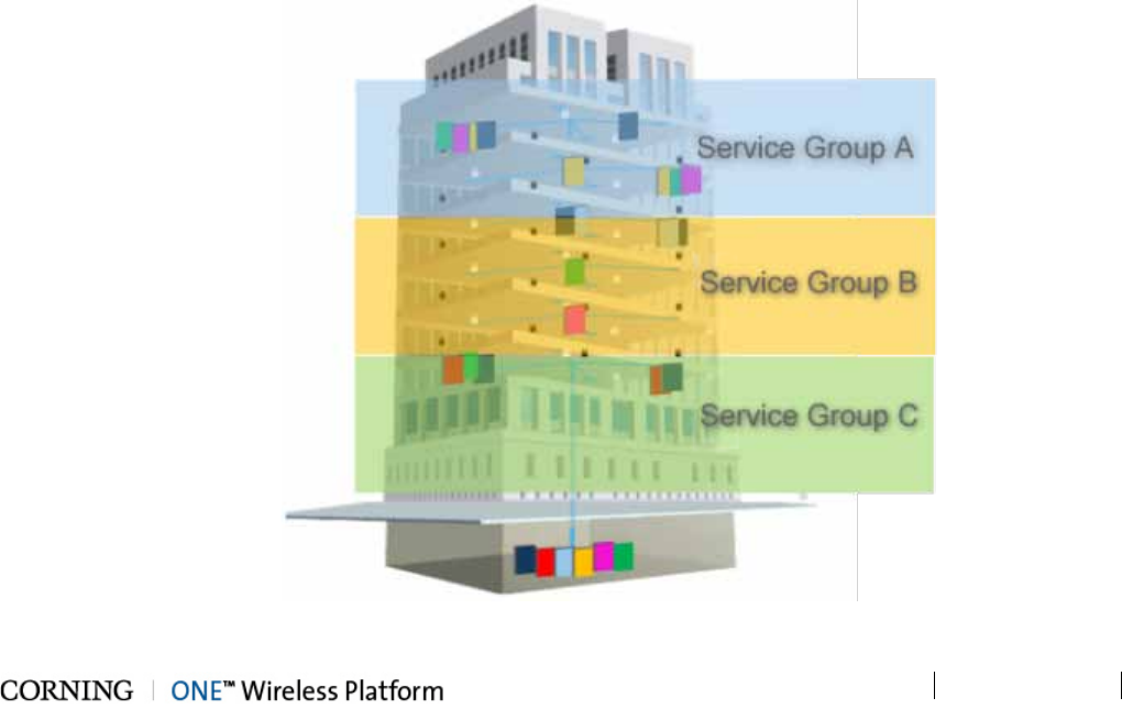
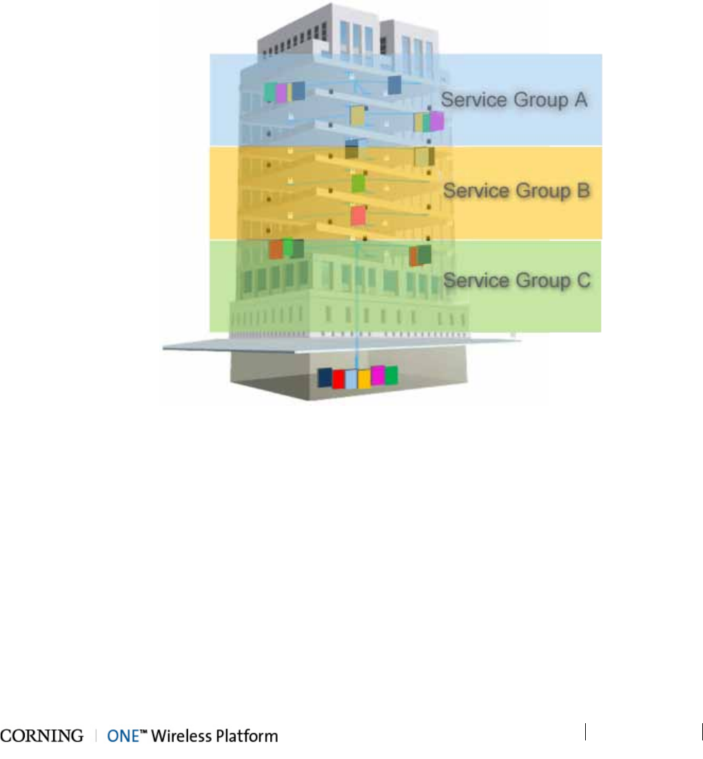
The following figure illustrates service distribution from the head-end to various locations on each remote floor. Each color
represents a specific service, where different combinations of services are distributed at various locations on the same floor
according to coverage requirements.
Figure 1-1. Illustration of Precise Service Distribution over Selected Remote Areas
Introduction P/N 709C011801 Page 16
DRAFT
1.2 Key Features and Capabilities
• Comprehensive service support - SISO/MIMO services.
• Supported services - CELL, PCS, LTE700 and AWS
• Flexible, configurable service distribution - advanced capacity and coverage management for better macro offload and
enhanced user experience.
• Broadband enabled:
• A range of ready-made fiber-optic (and power) composite cables simplify installation at all levels
• Fiber backbone unleashes unlimited RF Spectrum
• Easy scales to higher speeds requirements
• Ethernet Support - dedicated fiber link for Ethernet backhaul, enables optimal use and offload of Wi-Fi® resources.
• Scalable and customizable - infrastructure can be quickly expanded to support more services or increase coverage without
downtime
• Carrier-grade network management:
• Single-source, remote end-to-end field upgradable platform
• Ready for SON, HetNet and future network requirements.
1.3 General System Specifications and Requirements
1.3.1 Supported Browsers
ONE™ system Web GUI Management has been optimized to operate on the following browsers:
• Microsoft Internet Explorer v7.0 and higher
• Mozilla Firefox v3.2 and higher
• Sun Solaris Mozilla
• Google Chrome 8.0 and higher
1.3.2 Environmental and Regulatory Specifications
1.3.2.1 Temperature and Humidity
The environmental specifications listed below are relevant to all ONE™ solution devices.
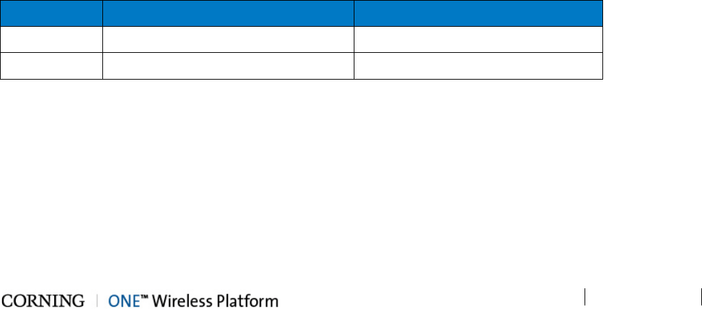
Operating
Storage
Temperature 0°C to +50°C (32°F to 122°F) -20° C to 85° C (-4°F to 185°F)
Humidity 95% (non-condensing) 95% (non-condensing)
Table 1-1. Temperature and Humidity Specifications
Introduction P/N 709C011801 Page 17
DRAFT
1.3.2.2 Safety and Regulatory Approvals
The safety and regulatory specifications listed below are relevant to all ONE™ devices.
Regulation/Standard
Category
Approval
Laser Safety FDA/CE 21 CFR 1040.10 and 1040.11 except for deviations pursuant to laser notice
no. 50 and IEC 60825-1
EMC CE EN 301 489, EN55022, EN 61000
FCC 47 CFR Part 15, 22, 24, 27
Safety
UL 60950
IEC 60825-1:2007
IEC 60825-2:2010
CAN/CSA-C22.2 No.60950-1-03
Fire Safety UL 2043 (applicable for Access Unit only)
Table 1-2. Safety and Regulatory Approvals
1.3.3 Power Specifications
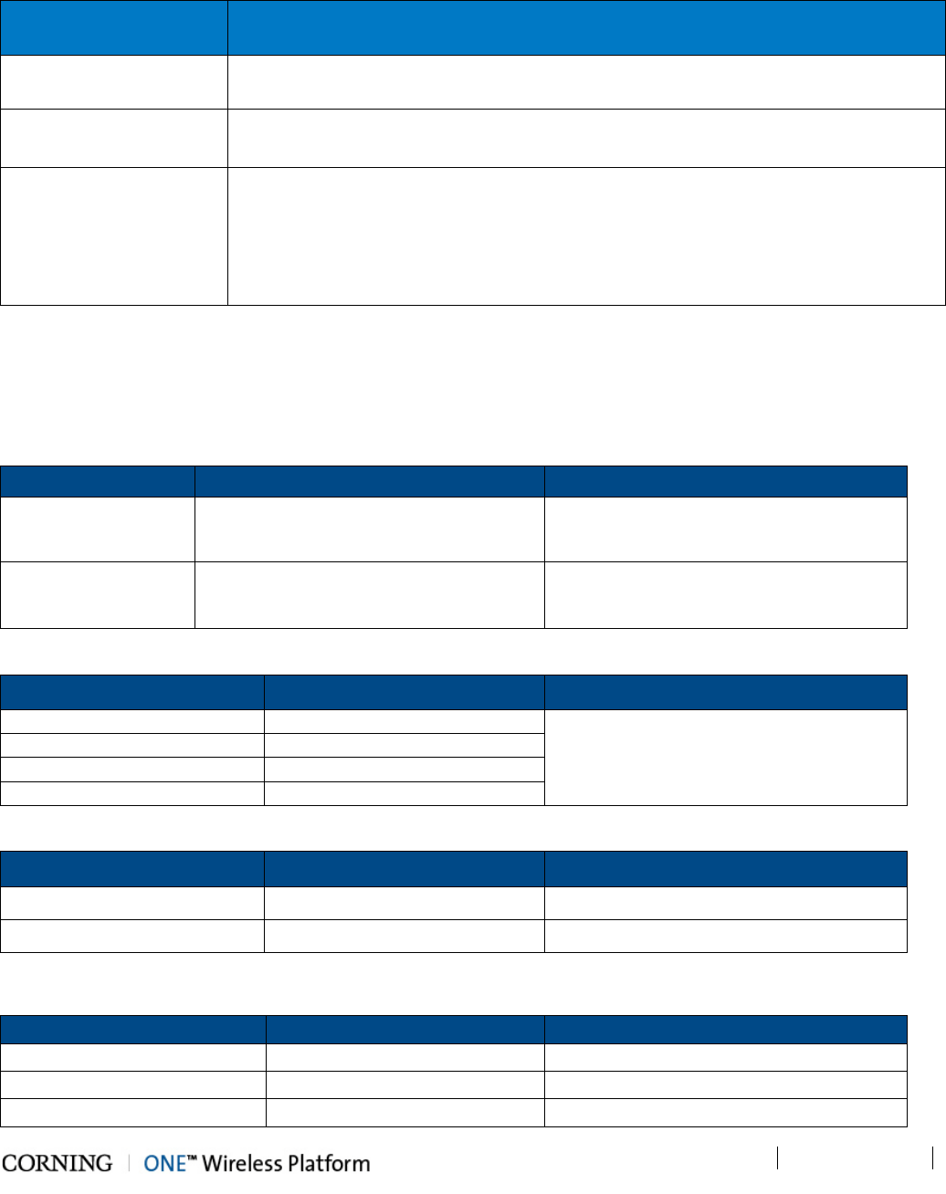
1.3.3.1 Power Input and Consumption
RF Head End Units Power Input Power Consumption for Full Chassis
HEU AC power source: 100 to 220 V AC Chassis with 12 RIMs and two RIX: 200 W
DC power source: 48 V DC
OIU AC power source: 100 to 220 V AC Chassis with 12 OIMs and two OIX: 300 W
DC power source: 48 V DC
Table 1-3. RF Headend Units Power Consumption
RAU + Add-On Modules
Max. Power Consumption
Power Input Range
RAU (alone)
37 V; 35 W
35 – 57 V DC
RAU + RxU
37 V; 60 W
RAU + GEM
37 V; 39 W
RAU + RxU + GEM 37 V; 64 W
Table 1-4. RAU Power and Current Consumption for Main Power Input
Device Input Range Power Consumption
For two PoE ports of 802.3af 43- 57 V DC 43 V; 30 W
For two PoE ports of 802.3at 52- 57 V DC 52 V; 62 W
Table 1-5. RAU Power and Current Consumption for Main Secondary Input
Digital Remote End Units Power Input Range Power Consumption
CEU 110 to 240 V AC (Fully occupied) 50 W
GEM installed in RAU See Table 1-4 See Table 1-4
GEU-S 42-57 V DC 4.5 W
Introduction P/N 709C011801 Page 18
DRAFT
Table 1-6. Digital Path Remote End Power Specifications
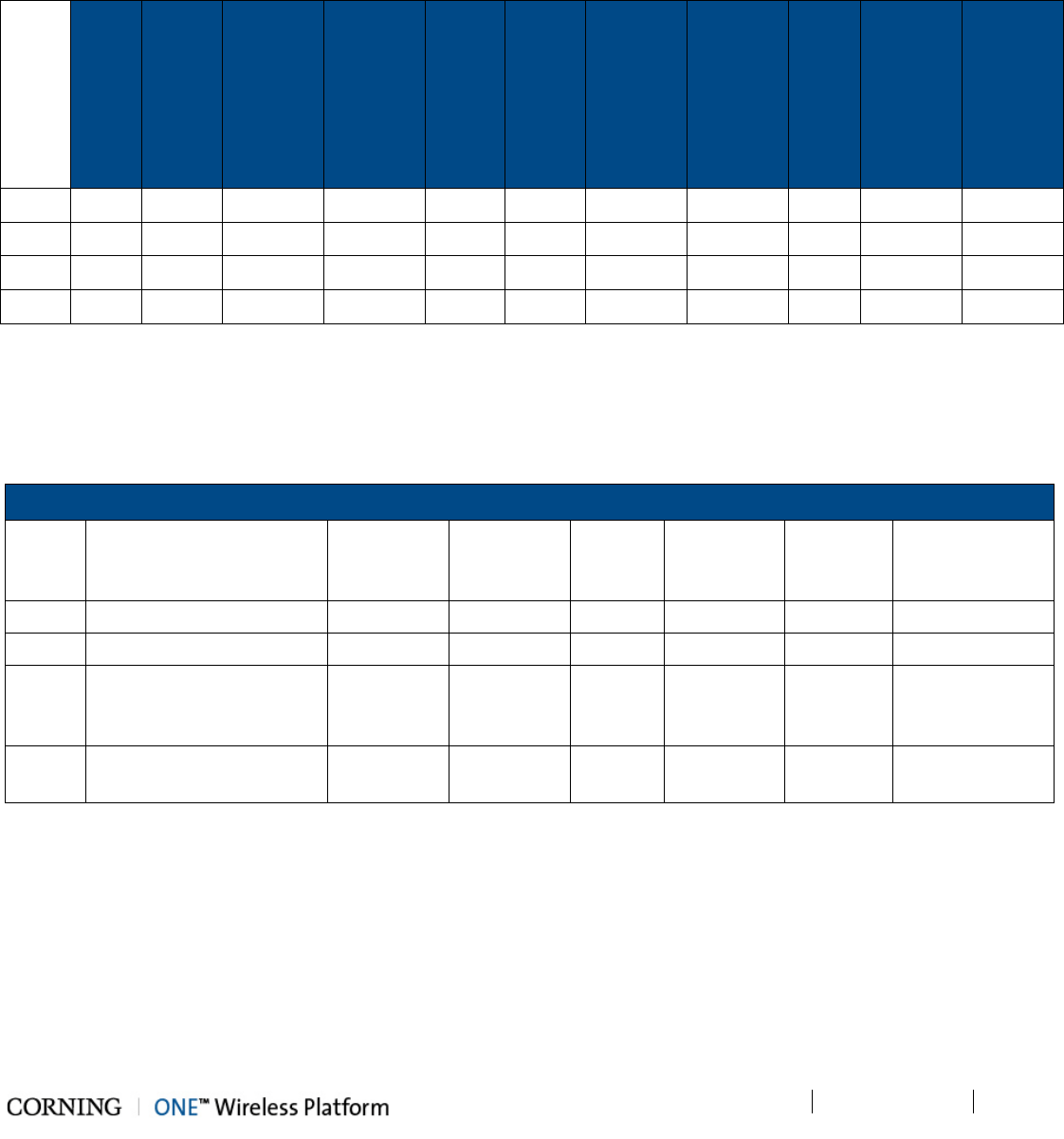
1.3.3.2 Cable Gauge Requirements
Table 1-7 provides the information required to calculate the required power supply for the remote units.
RAU
SISO
(ft)
RAU
SISO
+
GEM
(ft)
RAU SISO
+
GEM
Supporting
PoE
RAU SISO
+
GEM
Supporting
PoE+
(ft)
RAU
MIMO
(ft)
RAU
MIMO
+
GEM
(no
PoE)
(ft)
RAU
MIMO
+
GEM
Supporting
PoE
(ft)
RAU
MIMO
+
GEM
Supporting
PoE+
(ft)
GEU-S
(ft)
GEU-S
Supporting
PoE
(ft)
GEU-S
Supporting
PoE+
(ft)
22AWG 540 490 410 100 310 290 290 100 2000 310 80
20AWG 870 780 650 160 500 460 460 160 3200 500 130
16AWG 2200 1900 1600 400 1200 1100 1100 400 8200 1200 350
14AWG 3500 3100 2650 650 2010 1800 1800 650 1350 2000 550
Table 1-7. Required Cable Gauge
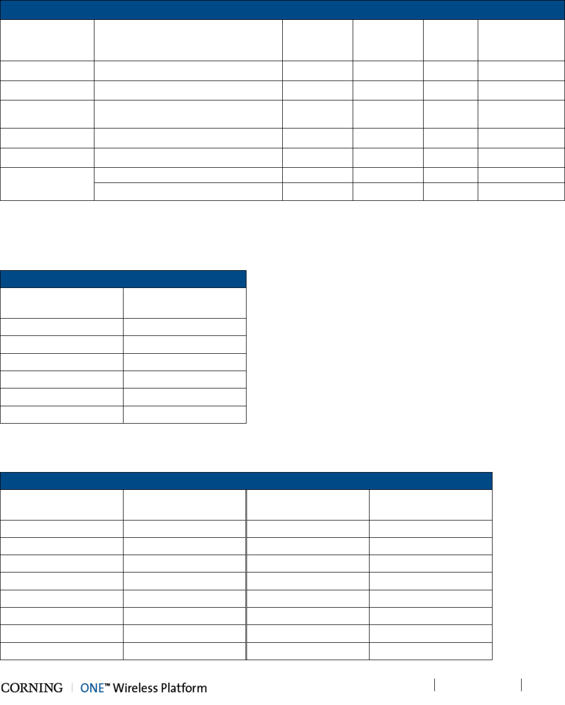
1.3.3.3 Power, Heat and Rack Specifications
Table 1-8 and Table 1-9 provide the power, heat and rack specifications for the headend and remote end ceiling equipment.
Headend/Telco Rms
P/N
Description
Min-Max
Voltage
(VAC)
Max Power
Draw
(Watts)
No. of
Units
Heat
(BTU/hr)
Rack
Space
19-in (RU)
Dimensions (in)
HEU Headend Unit 100 -220 200 1 680 4 7 x 17.3 x 18.9
OIU Optical Interface Unit 100 - 220 300 1 1020 4 7 x 17.3 x 18.9
CEU Centralized Ethernet Unit
(3 x CEMs – Centralized
Ethernet Modules)
110 - 240 50 1 170 1 1.75 x 17 x 8.5
ICU Intermediate Centralized
Unit (4 x 200 W PSMs)
110 - 240 930 1 442 1 1.75 x 17 x 19.2
Table 1-8. Power, Heat and Rack Specifications for Headend Equipment
Introduction P/N 709C011801 Page 19
DRAFT
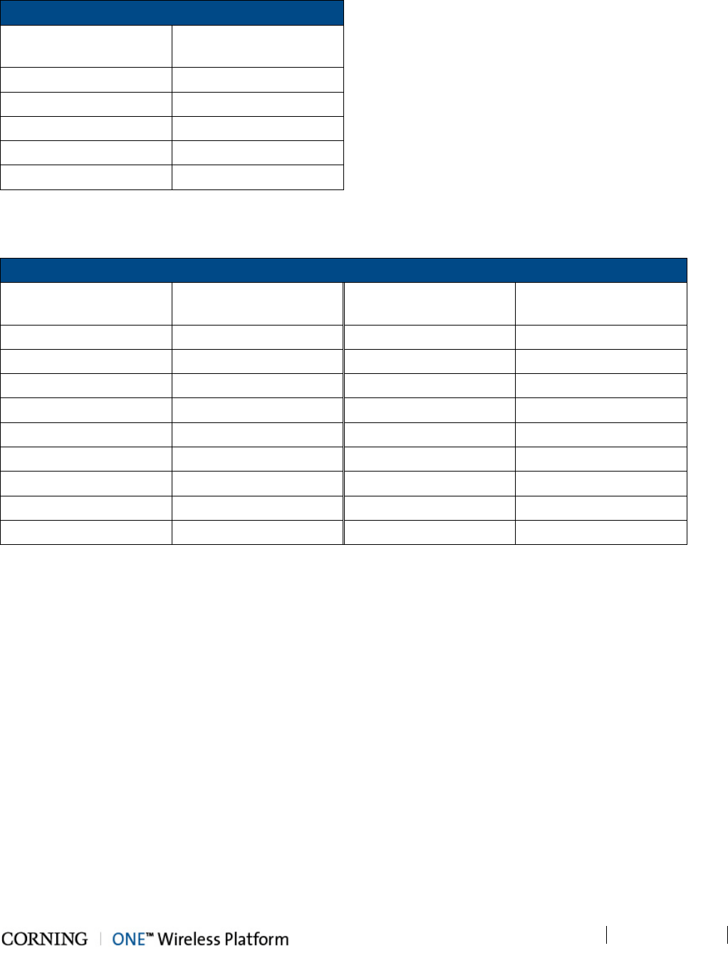
Ceilings
P/N
Description
Min-Max
Voltage
(VDC)
Max Power
Draw (Watts)
Heat
(BTU/hr)
Dimensions (in)
RAU Remote Access Unit 37 - 57 35 119 13.1 x 13.1 x 4
RxU Remote Expansion Unit 37 - 57 25 85 1.1 x 12.8 x 9.8
RAU + RxU Remote Access Unit + Remote
Expansion Unit 37 - 57 60 204 13.1 x 13.1 x 4
GEM Gigabit Ethernet Module 37 - 57 4 14 1.3 x 3.8 x 5.9
GEU-S Gigabit Ethernet Unit - Standalone 37 - 57 4 14 5 x 10.5 x 3.3
GEM Supporting
PoE
For two PoE ports of 802.3af: 43V; 30W
For two PoE ports of 802.3at: 52V; 62W
Table 1-9. Power, Heat and Rack Specifications for Ceiling Equipment (Remote End)
1.3.3.4 Remote End Distance and Power Draw Matrix
Table 1-10, Table 1-11, Table 1-12 and Table 1-13 provide the distance and power draw specifications for the remote end units.
RAU SISO
Composite 16 AWG
Tether Distance (ft.)
Draw (Watts)
10 - 50 36
60 - 270 37
280 - 480 38
490 - 690 39
700 - 850 40
860 - 900 41
*Min/Max VDC = 37/57 @ 1.49 Amps, 85% efficiency
Table 1-10. Remote End Distance and Power Draw for (Standalone) RAU SISO
RAU + RxU (MIMO)
Composite 16 AWG
Tether Distance (ft.)
Draw (Watts)
Composite 16 AWG
Tether Distance (ft.)
Draw (Watts)
10 – 100 62 570 – 610 70
110 – 170 63 620 – 660 71
180 – 240 64 670 – 710 72
250 – 320 65 730 – 750 73
330 – 380 66 760 – 790 74
390 - 440 67 800 – 830 75
450 - 510 68 840 – 860 76
520 - 560 69 870 - 900 77
*Min/Max VDC = 37/57@ 1.49 Amps, 85% efficiency
Introduction P/N 709C011801 Page 20
DRAFT
Table 1-11. Remote End Distance and Power Draw for RAU + RxU (MIMO)
GEM Supporting PoE 802.3af
Composite 16 AWG
Tether Distance (ft.)
Draw (Watts)
10 - 40 31
50 - 340 32
350 - 660 33
670 - 890 34
900 35
*Min/Max VDC = 43/57 @ 1.49 Amps, 85% efficiency
Table 1-12. Remote End Distance and Power Draw for GEM w/PoE.3af
GEM Supporting PoE 802.3at
Composite 16 AWG
Tether Distance (ft.)
Draw (Watts)
Composite 16 AWG
Tether Distance (ft.)
Draw (Watts)
10 - 80 64 590 - 620 73
90 - 170 65 630 - 670 74
180 - 230 66 680 - 710 75
240 - 300 67 720 – 750 76
310 - 370 68 760 – 790 77
380 - 420 69 800 - 820 78
430 - 470 70 830 - 850 79
480 - 530 71 860 - 890 80
540 - 580 72 900 81
*Min/Max VDC = 52/57 @ 1.49 Amps, 85% efficiency
Table 1-13. Remote End Distance and Power Draw for GEM w/PoE.3at
Introduction P/N 709C011801 Page 21
DRAFT
1.3.4 Dimensions and Weight of Units
Table 1-14, Table 1-15 and Table 1-16 describe the physical specifications of the ONE™ headend and remote end units.
Unit Dimensions (H x W x D) Weight:
HEU 7 x 17.3 x 18.95 in (177.8 x 440 x 481.7 mm) Chassis: 37 lbs (16.8 kg)
Per RIM: 1.9 lbs (0.9 kg)
Per RIX: 1.54 lbs (0.7 kg)
HCM: 2.2 lbs (1.0 kg)
PSM: 1.98 lbs (0.9 kg)
OIU 7 x 17.3 x 18.95 in [177.8 x 440 x 481.7 mm] Chassis: : 37 lbs (16.8 kg)
Per OIM: 1.5 lb (0.7 kg)
Per OIX: 1.54 lb (0.7 kg)
ACM: 2.2 lb (1.0 kg)
PSM: 1.98 lb (0.9 kg)
Table 1-14. RF Path Headend Units
Unit Dimensions (H x W x D) Weight:
ICU 1.74 x 17 x 19.2 in (44.4 x 431.8 x 11.96 mm) 5.5 lb (2.5 kg) – without PSM
RAU (including
mounting bracket)
13.1 x 13.1 x 4 in (332.7 x 332.7 x 101.6 mm) RAU only = 7.93 lb (3.6 kg);
RAU + RxU + GEM = 12.2 lb (5.5 kg)
Table 1-15. RF Path Remote Units
Unit Dimensions (H x W x D) Weight: lbs [kg]
CEU 1.71 x 17 x 8.5 in (43.65 x 431.8 x 216 mm) -
GEM 1.28 x 3.79 x 5.95 in (32.7 x 96.3 x 151.3 mm) 1.1 lb (0.5 kg)
GEU-S 5.01 x 10.51 x 3.26 in (including mounting bracket)
(127.5 x 267 x 83 mm)
2.64 lb (1.2 kg)
Table 1-16. Digital Path Units
Introduction P/N 709C011801 Page 22
DRAFT
1.3.5 Optical Specifications
Parameter Specification
Optical Output Power < 9 dBm
Max. Optical Budget 5 dB
Optical Connector OIM: MTP® connector
RAU: LC APC SM
Fiber Type Corning® SMF-28® or Compatible
Wavelength 1310±10 nm (Standard)
Maximum Distance (headend to remote end) 2 km (SMF)
Table 1-17. Optical Specifications
Introduction P/N 709C011801 Page 23
DRAFT
1.3.6 System Architecture and Topologies
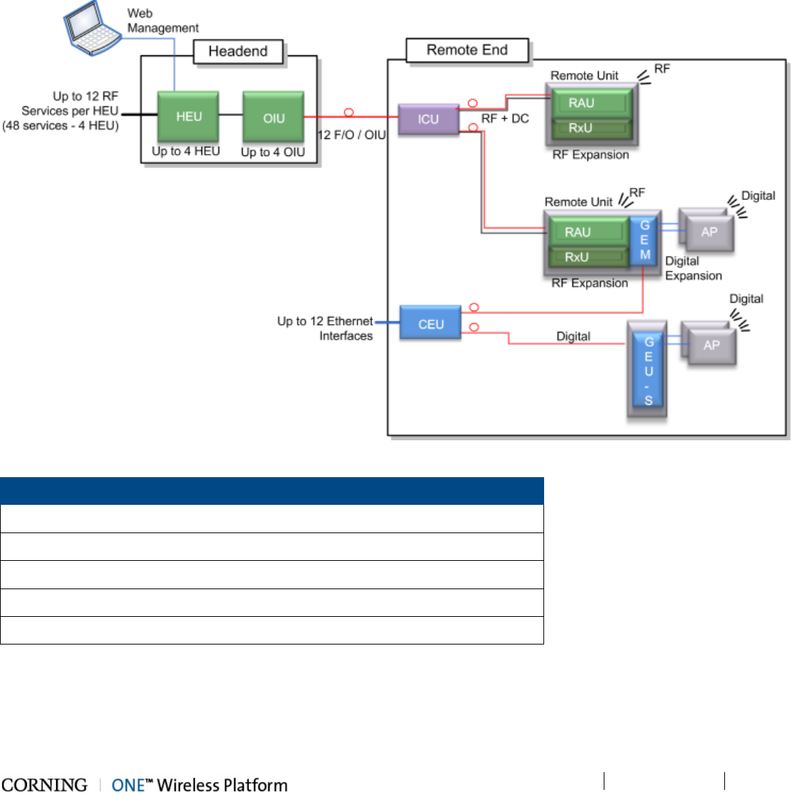
The ONE™ solution fiber-optic infrastructure is used to transmit both RF and digital services:
• RF services – Broadband RF distribution over fiber-optics infrastructure transfers converged wireless services from the
headend towards Remote Access Units (RAU) deployed at the remote end locations according to user defined
configuration.
• Digital services – fiber-optics infrastructure transfers digital services from the corporate LAN to Gigabyte Ethernet Modules
(GEM) and then 3rd party equipment deployed on each floor.
Figure 1-2. ONE™ Solution Basic Architecture
Acronyms
HEU = Headend Unit GEU-S = Gigabit Ethernet Unit-Standalone
RIM = Radio Interface Module ICU = Intermediate Centralized Unit
RAU = Remote Access Unit CEU = Centralized Ethernet Unit
RxU = Remote Expansion Unit OIU = Optical Interface Unit
GEM = Gigabit Ethernet Module OIM = Optical Interface Module
Table 1-18. Acronyms in System Architecture
Introduction P/N 709C011801 Page 24
DRAFT
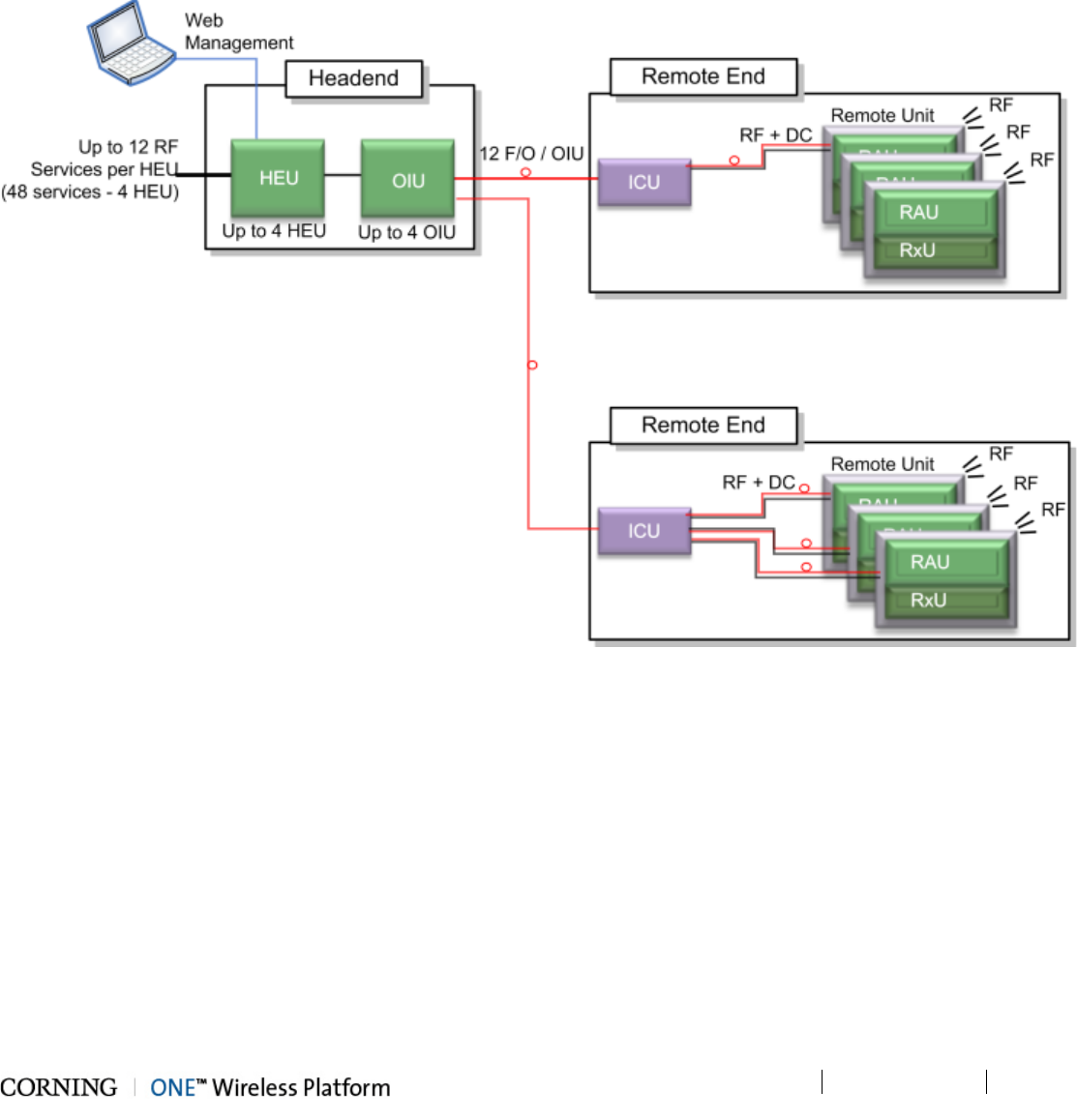
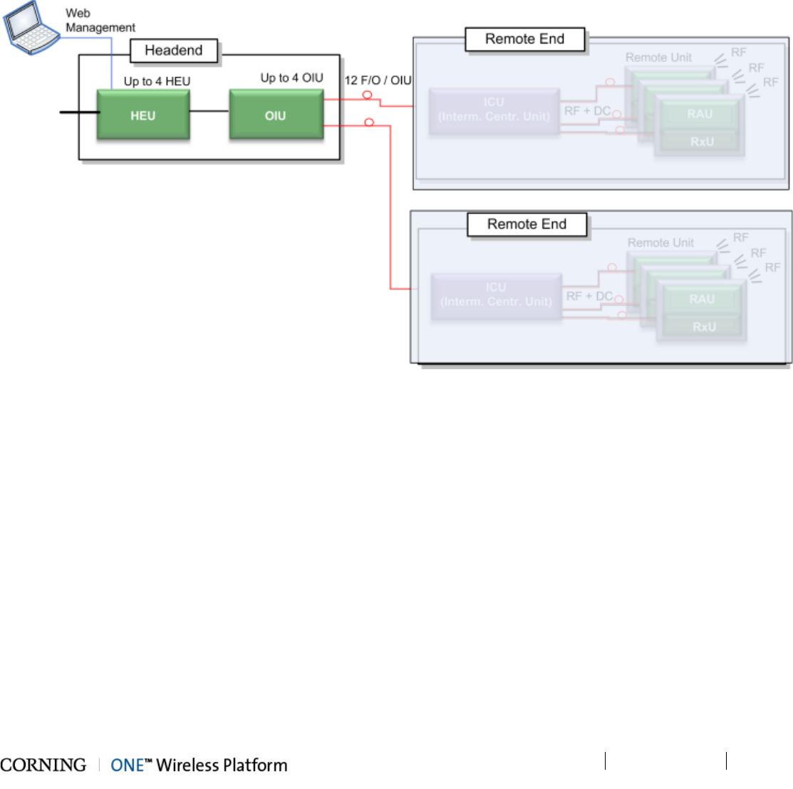
1.3.6.1 RF Path
At the headend, RF signals from the RF signal sources (e.g. BTS/BDA) are conditioned by service specific (conditioner)
modules in the HEU (Headend Unit) and organized into (up to three) user configurable sectors. The conditioned RF signals are
converted to optic signals by the (wideband) OIU (Optic Interface Unit) and specific sectors are routed towards selected remote
locations according to user defined configurations.
The optic fibers at the OIU are routed to the ICU (Integrated Centralized Unit) at the remote end. From the ICU the optic fibers
are distributed along with DC to the Remote Access Units (RAU).
Figure 1-3. ONE™ Solution RF Path Architecture
Introduction P/N 709C011801 Page 25
DRAFT
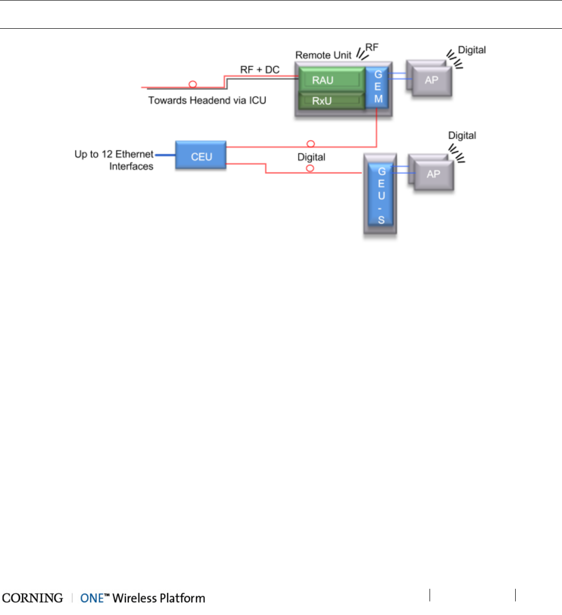
1.3.6.2 Digital Path
The Digital services from the corporate LAN (received via Ethernet Switch) are converted to optic signals by the CEU
(Centralized Ethernet Unit) and routed over optic fibers towards the GEM units. The optical traffic is then converted to 1GbE by
the GEM (Gigabit Ethernet Modules) modules and distributed to two third party equipment such as Access Points, Ethernet
switch, etc.
Note: GEMs can be connected to the CEU either directly, or via an ICU (described in section 1.3.6.1 ). In that case, the ICU can
also provide DC to the GEMs.
Figure 1-4. ONE™ Solution Digital Path Architecture
Introduction P/N 709C011801 Page 26
DRAFT
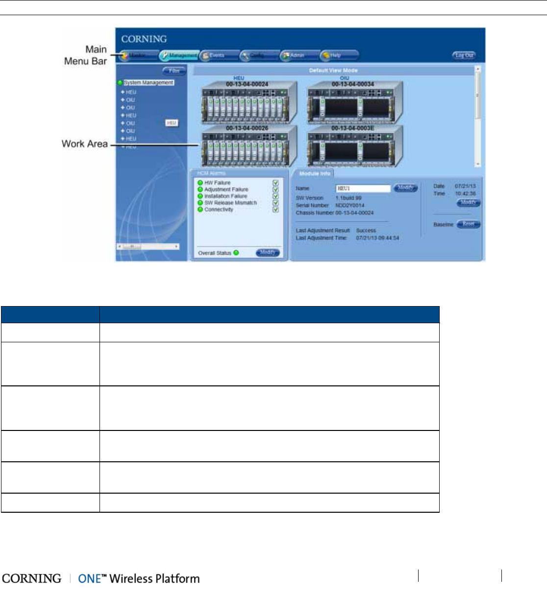
1.4 ONE™ WEB Management Application
The ONE™ solution consisting of the HEU and its hosted elements is managed via a WEB session to the HEU. The GUI based
WEB management application provides all the required configuration, management and monitoring options for the ONE™
system. The ONE™ Web management application consists of the Main Menu bar, where the displayed side-bar and work area
options vary according to the selected menu option.
Note: Refer to the ONE™ HCM User Manual for a complete description of the Web Management application.
Figure 1-5. Main Window (Config Tab - Default Display)
The Main Menu Bar includes the following tabs:
Tab Description
Monitor N/A
Management Displayed upon login by default. Displays general module information and
device alarms and provides the configuration options for the available
selected site devices. A general overview is given in section 1.4.1.
Events Displays the events that occurred on the monitored devices and enables
generating reports. Configuration changes that are initiated by the network
manager are not considered events display. See Events Display section.
Config Set-up tool used for initial system set-up, commissioning of system devices
and adjustment procedure.
Admin Provides administration options such as firmware upgrade, user
management options and IP settings required for receiving traps.
Help Provides access to Online Help
Table 1-19. Main Menu Tabs
Introduction P/N 709C011801 Page 27
DRAFT
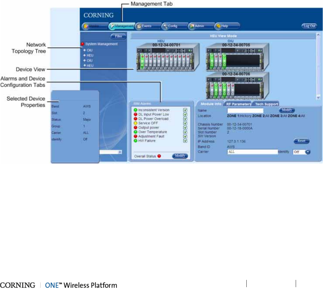
1.4.1 Overall Device Display - Configuration Tab
The Config window is displayed by default upon login and includes the following for each selected element:
• Network Topology Tree - hierarchically displays the connected and available site devices and their status.
• Device Configuration Tabs - device specific which include the configurable parameters (e.g. service control, RF parameters)
and general information (e.g. device name, Firmware version)
• Device View - visualization of device, with LEDs corresponding to the device status. Device view can be used for fault
sourcing at a glance.
• Alarms - displays the device alarms for fault sourcing and provides alarm masking options
Note the following:
• The device selected in the Network Topology Tree appears green in the Device View Mode area
• Point to module in Device View to display property info
Figure 1-6. Config Tab
Introduction P/N 709C011801 Page 28
DRAFT
1.5 User Controlled Service Group Distribution
ONE™ fiber-optics infrastructure allows various combinations of SISO and MIMO services to be routed from the headend to
specified remote locations on each floor, according to user defined configurations. This allows optimizing service coverage and
provides equipment savings. While the fiber-optics infrastructure is common, the services can be routed via service provider
shared or dedicated equipment. By default, the system is configured to support a single service group: all services are
transferred to all remote locations. This default configuration can be easily modified according to site requirements.
The following figure illustrates service distribution from the head-end to various locations on each remote floor. Each color
represents a specific service, where different combinations of services are distributed at various locations on the same floor
according to coverage requirements.
Figure 1-7. Illustration of Service Group Distribution
Introduction P/N 709C011801 Page 29
DRAFT
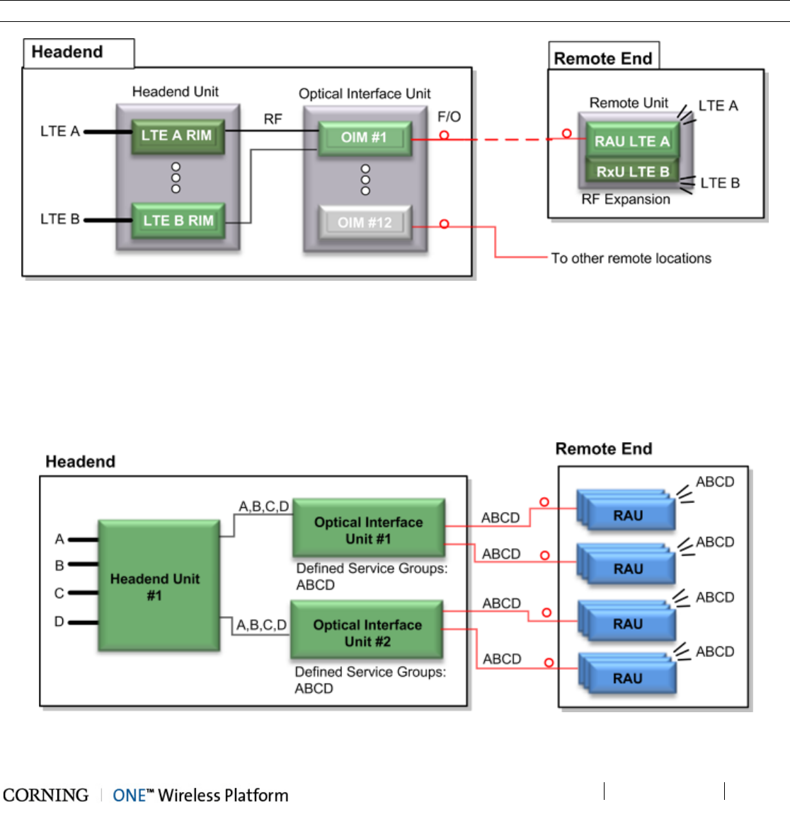
1.5.1 MIMO Configurations
MIMO topologies provide more density by using two independent RF paths for the same service, where the independent paths
are implemented by dedicated modules along the path.
MIMO configuration is implemented by routing the two RF bands over dedicated RF paths at both the entry point (in the
Headend Unit) and at the exit point (at the Remote Unit). Note that the Optical Interface Unit is wideband and the services are
combined in a single OIM for routing to the same Remote End Unit. At the Remote End Unit, the services are distributed by two
dedicated modules.
Note: MIMO configuration can also be implemented by two separate Remote End Units.
Figure 1-8. Example of MIMO Configuration
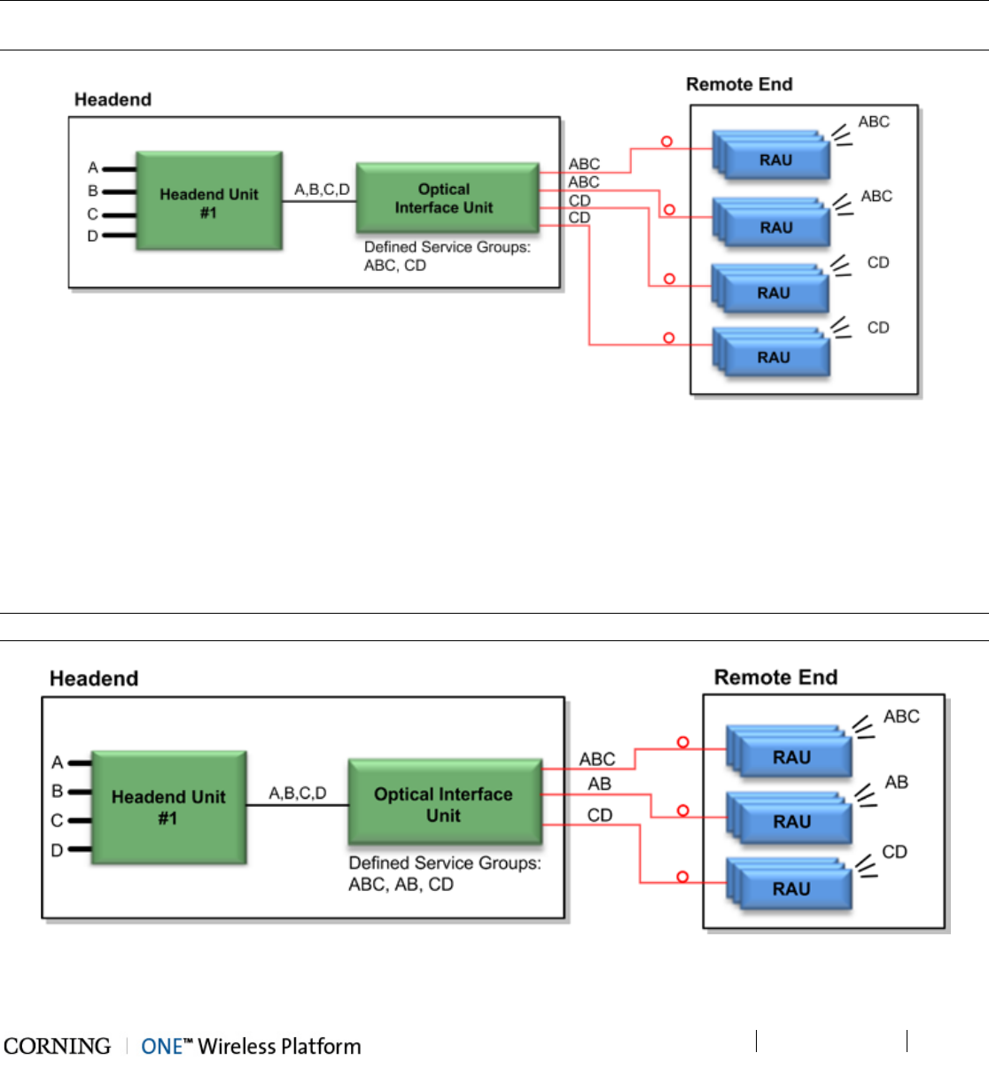
1.5.2 Single Service Group Example
In this example, all four services (A,B,C,D) are routed to all (up to 72) remote locations. In the illustrated topology, a single HEU
conditions the services and feeds them to two OIU systems for conversion to optic signals. Each OIU supports up to 36 RAU
(Remote Access Units).
Figure 1-9. Single Service Group Configuration
Introduction P/N 709C011801 Page 30
DRAFT
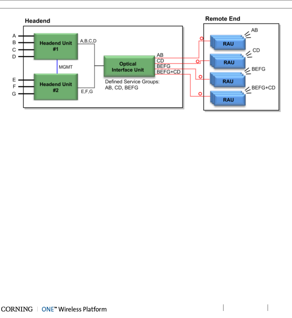
1.5.3 Dual Service Group Example
In this example, two service groups are defined: A,B,C and C,D. Note that a service can be allocated to any of the service
groups at the same time. For example, service C is allocated to both service groups. Both service groups are routed to the OIU
for optic conversion. Each OIU module (OIM) can be configured to support either one or (if they do not have a common band) to
both service groups and the corresponding services are routed from the OIM to its hosted RAU units.
NOTE: In the example below, band C is common to both Service groups #1 and #2; therefore, an OIM cannot be assigned both
service groups (i.e. ABC + CD).
Figure 1-10. Example of Dual service group Configuration
1.5.4 Tri Service Group Example
In this example, three service groups are defined: ABC, AB, CD. Note that a service can be allocated to any of the service
groups at the same time. For example, services C and B are allocated to two of the service groups. The services are routed to
the OIU for optic conversion. Each Optical Interface Module (OIM) can be configured to be included in either one, two or three
service groups in any combination and the corresponding services are routed from the OIM to its hosted RAU units.
Note: An OIM cannot support two service groups that have a common band (e.g. ABC and BC, or ABC and CD).
Figure 1-11. Example of Three Service Group Configuration
Introduction P/N 709C011801 Page 31
DRAFT
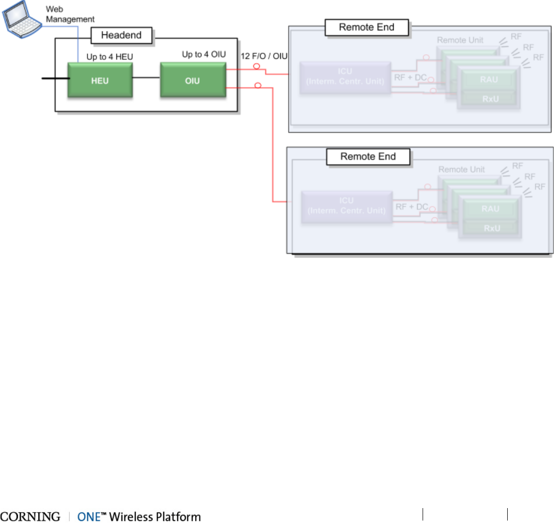
1.5.5 Tri Service Group Example with Two HEUs
This tri-service group example supports two HEUs. In this topology, the services routed via the two HEUs can be grouped in any
combination between the two, providing up to three service groups. These groups of services are all routed towards a common
OIU. Each OIU module (OIM) can be configured to support any (legal) combination of service groups and the corresponding
services are routed from the OIM to its hosted RAU units.
Note: Multiple service groups allocated to the same OIM cannot share any identical frequency bands.
Figure 1-12. Example of Tri-Service Group Configuration with Two HEUs
Unit Descriptions - RF Path P/N 709C011801 Page 33
DRAFT
2 Unit Descriptions - RF Path
This chapter provides detailed descriptions of the ONE™ solution components. The descriptions are organized according to RF
and Digital path headend and remote end components. This includes port and LED interface descriptions.
2.1 RF Path - Headend Components
ONE™ RF Path coverage solution includes the following headend elements:
• HEU – Headend Unit
• OIU – Optical Interface Unit
Figure 2-1. RF Path Headend Components
Unit Descriptions - RF Path P/N 709C011801 Page 34
DRAFT
HEU (Headend Unit)
The HEU performs the following main functions:
• Conditions (up to 12) RF sources to a level required for feeding to the Optical Interface Unit (OIM).
• Enables the configuration of up to three sectors consisting of groups of RF services.
• Main HEU – includes HCM module enabling single source control and management of the ONE™ solution RF path
• Auxiliary HEU – includes ACM modules and is managed via the HCM in the Main HEU
Note: Only one HEU per system can be installed with an HCM module and serves as the “Main HEU”. Any additional HEU
chassis are installed with ACM modules and are considered “Auxiliary HEUs”.
Each HEU supports up to 12 services. For additional services or density, two or more HEU units can be cascaded so that the
Auxiliary HEUs are managed from the Main HEU (via the HCM). For HEU installation procedure, see section 5.1.2.
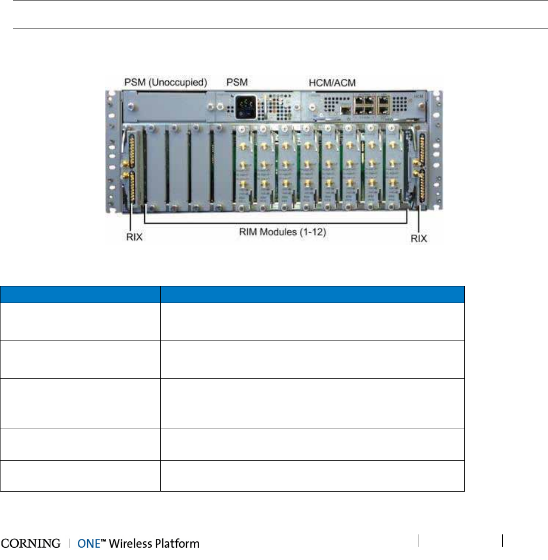
Figure 2-2. HEU Front Panel with Installed Modules
Module Description
HCM (Headend Control Module)
Provides system management and control functions. The HEU in
which the HCM is installed serves as the Main HEU. See
section 2.1.1.1.
ACM (Auxiliary Control Module)
Provides management connections to the HCM. HEU chassis with
ACM modules are considered Auxiliary HEUs and are managed via
the HCM.
PSM (Power Supply Modules)
PSM-AC:100 - 240 V AC
PSM-DC: 48 V DC
Note: If two are installed, both must be powered on. See
sections 2.1.1.6. (PSM-AC) and 2.1.1.7 (PSM-DC).
RIM (RF Interface Module) Provides the service specific RF interface to the RF source. See
section 2.1.1.3.
RIX (RF Expander Module) Service specific conditioner units. See section 2.1.1.4.
Table 2-1. HEU Front Panel Interface Definitions
Unit Descriptions - RF Path P/N 709C011801 Page 35
DRAFT
2.1.1 HEU (Headend Unit)
HEU hosts the following modules:
1. HCM- Headend Control Module; overall system management module (see section 2.1.1.1)
2. ACM – Auxiliary Control Module; provides interfaces for management of domestic modules via HCM; installed in HEUs’ in
configurations with more than one HEU (see section 2.1.1.2)
3. RIM - Radio Interface Module; RF source conditioner (see section 2.1.1.3)
Up to 12 RIMs can be hosted by the HEU
4. RIX - Radio Interface Expander; HEU to OIU interface module (see section 2.1.1.4).
Note: For configurations with one RIX an ETM is required for terminating the unused Expander slot.
5. PSM- Power Supply Module; AC or DC power supply (see section 2.1.1.5).
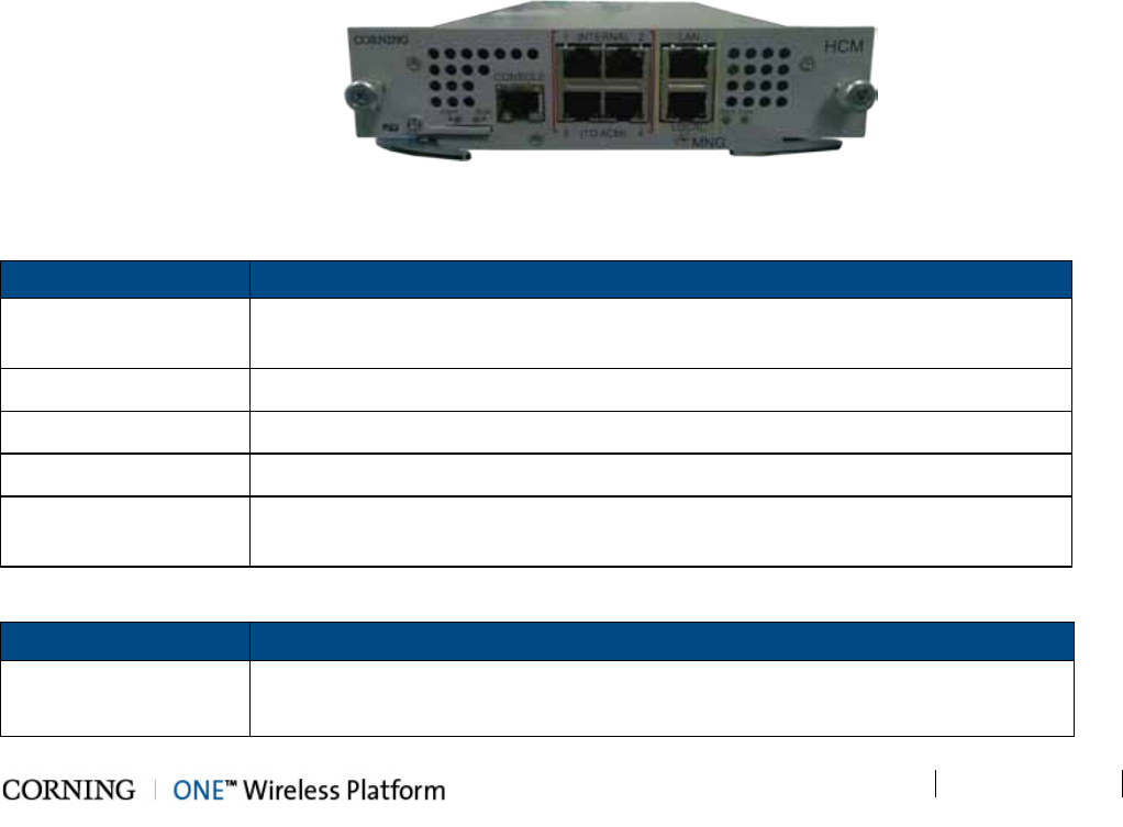
2.1.1.1 HCM (Headend Control Module)
Overall system management and control capabilities are performed via the HCM, which is installed in an HEU chassis (one
HCM per system installation). The HEU hosting the HCM module serves as the Main HEU (any additional HEU chassis is
installed with an ACM).
The HCM interfaces to the corporate LAN and to up to four ACM modules installed in any additional HEU and in OIU chassis
(see section 2.2). The HCM includes Local and LAN management ports and LED status indicators.
Figure 2-3. HCM Module
Table 2-2 and Table 2-3 provide a description of the HCM ports and LED status indicators.
Port Description
INTERNAL (TO ACM) Four RJ45, 100Mb Ethernet ports - used for management of connected OIU
systems (and/or HEU Slaves).
LAN RJ-45, 1Gb Ethernet port - connects to the corporate LAN for remote management
LOCAL RJ-45, 1Gb Ethernet port - local configuration and management
CONSOLE RJ-45, serial port - local configuration for service personnel
SD Card Slot Supports uSD cards up to 32 GB (used for saving and importing configuration files
between different HEU chassis)
Table 2-2. HCM Ports
LED Description
PWR Steady Green - Power input detected by HCM
Off – No power is supplied to the unit
Unit Descriptions - RF Path P/N 709C011801 Page 36
DRAFT
LED Description
RUN
Steady Green – HCM Boot up sequence complete and module SW up and running
Blinking Green – HCM Boot up sequence in process
Off – No power supplied to the unit
SYS Steady Green – Overall status of the managed system is ok
FAN Steady Green – Normal operation status for all fans
Red – Fault indicated in at least one fan
Table 2-3. LED Description
Unit Descriptions - RF Path P/N 709C011801 Page 37
DRAFT
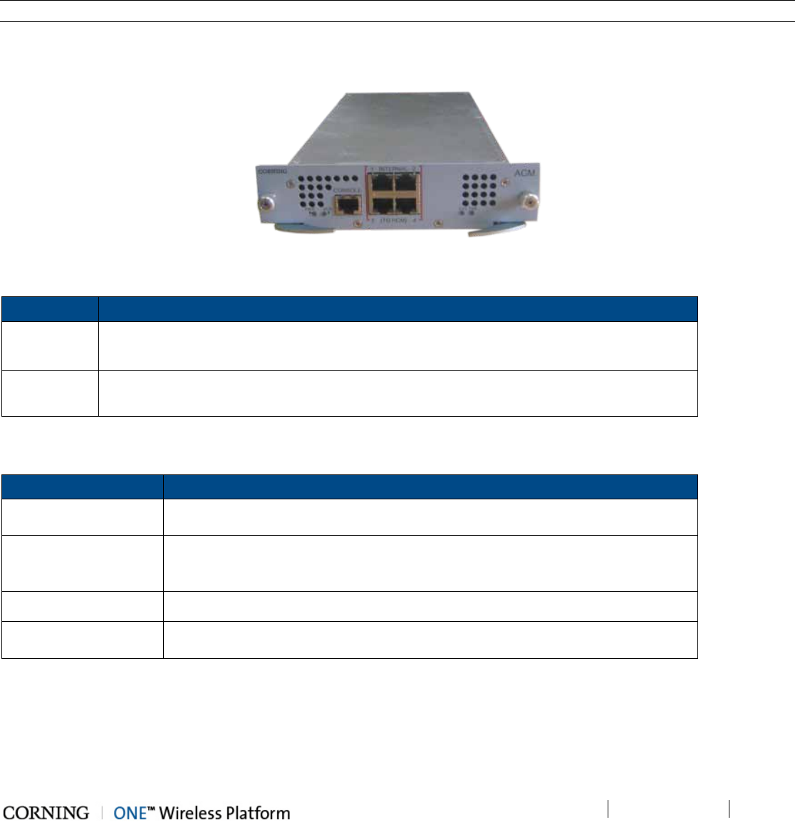
2.1.1.2 ACM (Auxiliary Control Module)
The ACM is installed in any additional HEU chassis in installations with more than one HEU (one HEU is installed with the
HCM).
The ACM provides the interfaces for remote management and control capabilities of the host chassis and connected modules
via a local connection to the HCM (see section 2.1.1.1).
Note: The ACM is also installed in each OIU chassis.
Figure 2-4. ACM Module
Table 2-4 and Table 2-5 provide a description of the ACM ports and LED status indicators.
Port Description
INTERNAL
(TO HCM) Four RJ45, 100Mb Ethernet ports used for OIU and/or HEU slave management connections
Console One RJ45, serial port used for basic IP configuration and local connection for service
personnel
Table 2-4. ACM Ports Description
LED Description
PWR
Steady Green - Power input detected by ACM
Off – No power is supplied to the unit
RUN
Steady Green – ACM Boot up sequence complete and module SW up and running
Blinking Green – ACM Boot up sequence in process
Off – No power supplied to the unit
SYS Steady Green – Overall status of the managed system is ok
FAN
Steady Green – Normal operation status for all fans
Red – Fault indicated in at least one fan
Table 2-5. ACM LED Indicators Description
Unit Descriptions - RF Path P/N 709C011801 Page 38
DRAFT
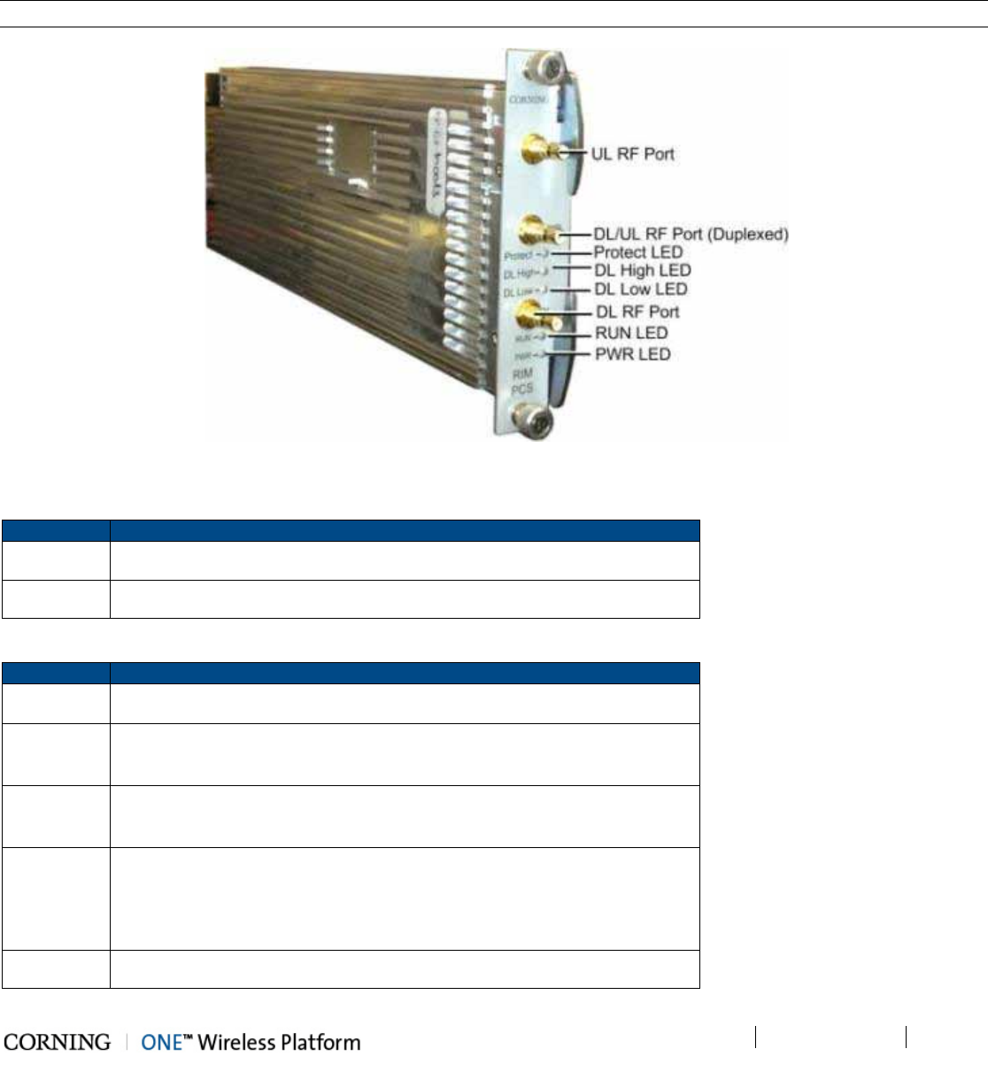
2.1.1.3 RIM/RIM-M (RF Interface Module)
The RIM/RIM-M module is a service specific RF conditioning module (up to 12 are installed in an HEU chassis) which interfaces
to the RF signal source. Each RIM supports both Simplex and Duplex RF connectors. LEDs provide status indications on signal
level and module operation.
Note: RIM-M modules support MIMO services (e.g.700 MHz LTE, AWS).
Figure 2-5. RIM Module
Table 2-6 and Table 2-7 provide a description of the RIM ports and LED status indicators.
Port
Description
DL/UL UL and DL simplex connections to the RF signal source
DUP Duplexed UL and DL connection to the RF signal source
Table 2-6. RIM Ports Description
LED
Description
Protect N/A
DL High Provides indication on DL RF level in conditioner module:
Off - DL RF input level in threshold range
Steady Red – Signal is 3 dB above max. expected power
DL Low
Provides indication on DL RF level in conditioner module:
Off - DL RF input level in threshold range
Steady Red – No signal or 15 dB below max. expected power
RUN
Steady Green - Power on and module SW has initialized and is up and
running
Blinking Green- Fault detected (e.g. RIM module SW halted) or SW
upgrade in process
Off - No power
PWR On - Input power is within required range
Table 2-7. RIM LED Descriptions
Unit Descriptions - RF Path P/N 709C011801 Page 39
DRAFT
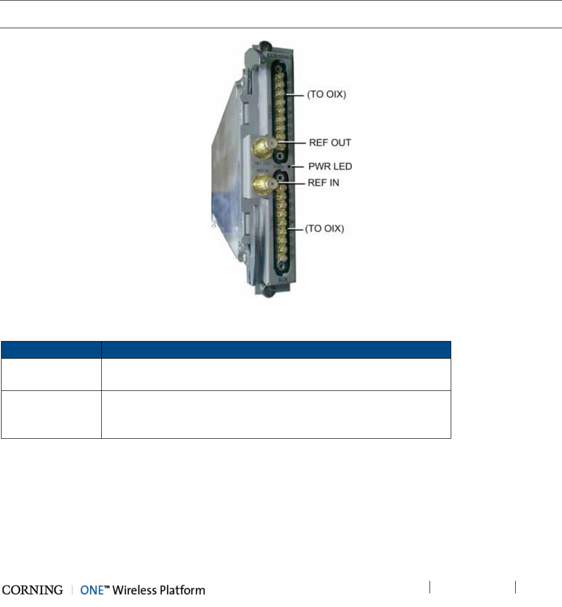
2.1.1.4 RIX (RF Expander Module)
The RIX Expander module provides the RF interface to the OIU unit. Up to two RIX Expander modules are installed in each
HEU chassis, providing support for up to four OIU (via OIU Expander modules - OIX).
IMPORTANT! An unoccupied Expander slot must be terminated with an (Expander Termination Module)
Note: The RIX and OIX Expander modules are similar in appearance but are NOT INTERCHANGEABLE. Each Expander
module is indicated as RIX or OIX on the bottom of the module.
Figure 2-6. RIX Expander Module Interfaces
Port Description
(TO OIX) Two 9 – pin connectors which serve as the RF interfaces to the OIX (in the
OIU). RIX supports connections to two OIXs via an Expander cable (ERFC).
REF OUT/REF IN
Two QMA connectors used for reference clock signal connections between
RIX modules.
Note: The reference clock passes from the Main HEU to all Auxiliary chassis.
Table 2-8. RIX Ports Description
Unit Descriptions - RF Path P/N 709C011801 Page 40
DRAFT
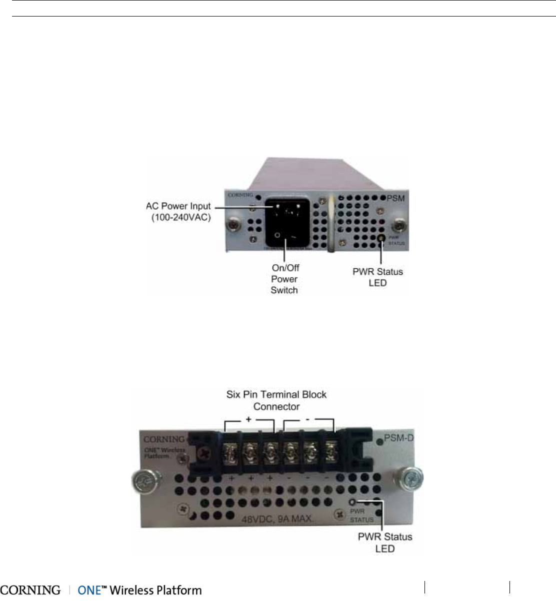
2.1.1.5 PSM (Power Supply Module)
Two types of Power Supply Modules are available:
• PSM-AC: 100 – 240 VAC;
• PSM-DC: 48 V DC; 9 A Max.
Note: The power rating for both PSM types is 300 W.
• The PSM modules are installed in HEU and in OIU chassis.
• Each HEU and OIU chassis can support two PSM modules, where the second PSM provides redundancy in case one of the
supplies fails.
• Both types of PSM modules (AC and DC) can be installed in the same chassis.
• If two modules are installed, both must be connected to their respective power source (AC or DC) and turned on at all times.
2.1.1.6 PSM-AC (Power Supply Module-AC Power Source)
The PSM-AC includes an AC power connector, on/off switch and Power Status LED. See Figure 2-7.
Figure 2-7. PSM-AC Power Supply Module
2.1.1.7 PSM-DC (Power Supply Module-DC Power Source)
The PSM-DC power source rating is 48 V DC; 9 A Max.; 300 W. The PSM-DC includes a six pin terminal block connector,
supporting up to three DC wire pairs.
Figure 2-8. DC Power Supply Module
Unit Descriptions - RF Path P/N 709C011801 Page 41
DRAFT
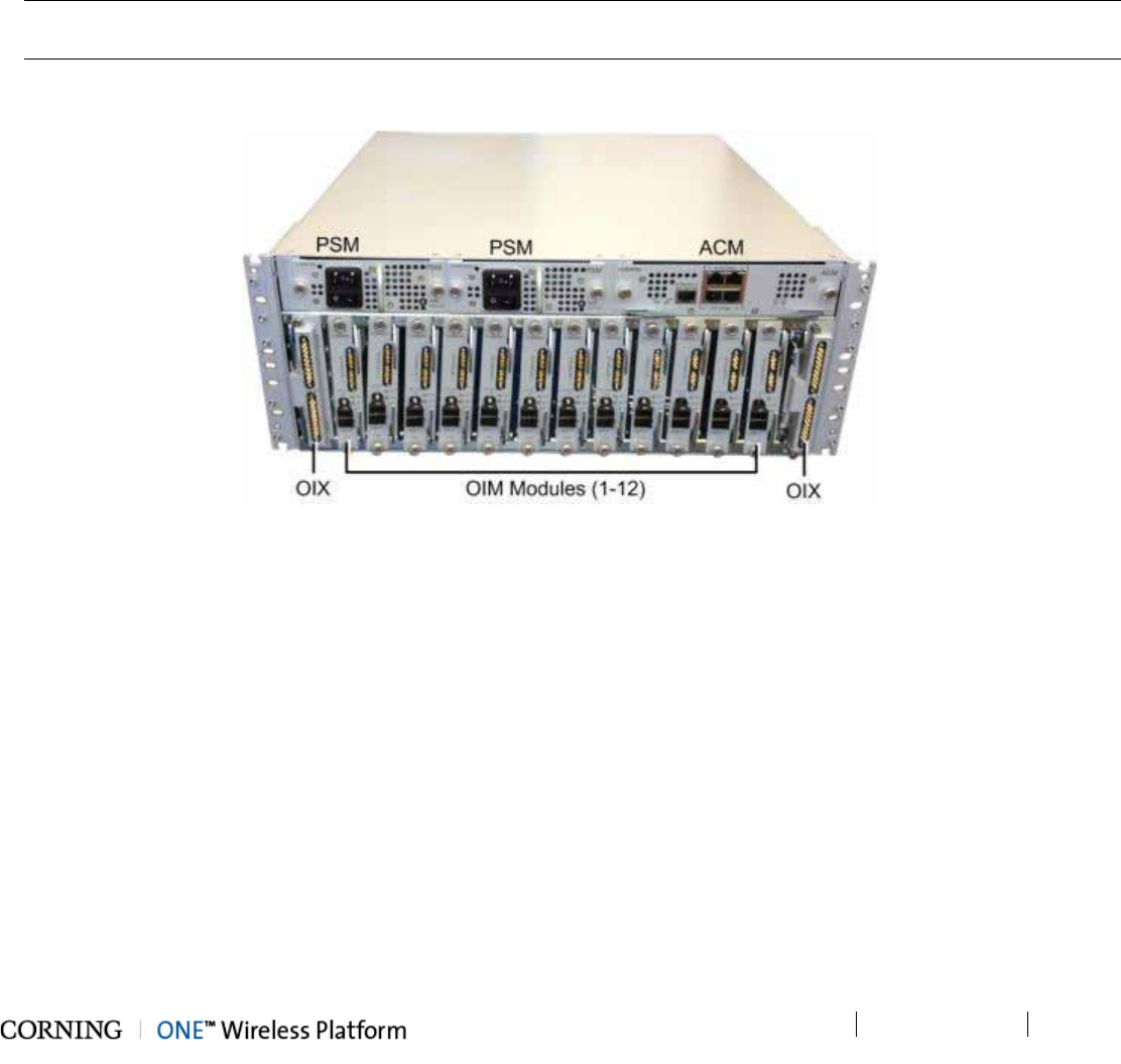
2.2 OIU (Optical Interface Unit)
The OIU interfaces to the HEU, performs the RF to optic conversion of the received signal and distributes the wireless RF
services to the RAU units over the fiber optic infrastructure to the remote site. Each OIU supports up to 12 SM optic fibers (one
fiber per OIM), which are routed to up to 36 RAU (three Remote Access Units per OIM).
OIU hosts the following modules:
• ACM - Auxiliary Control Unit; provides interfaces for management of OIU modules via HCM (see section 2.2.1)
• OIM- Optical Interface Modules; converts the RF to three Optical links (see section 2.2.2)
• OIX- Optical Interface Expander; OIU to HEU interface Module (see section 2.2.3)
Note: For configurations with one OIX an ETM (Expander termination module) is required for terminating the unoccupied
OIX slot.
• PSM (AC/DC) - Power Supply Module; powers the unit (see section 2.1.1.5)
Figure 2-9. OIU Front Panel with Installed Modules
Unit Descriptions - RF Path P/N 709C011801 Page 42
DRAFT
2.2.1 ACM (Auxiliary Control Module)
See section 2.1.1.2.
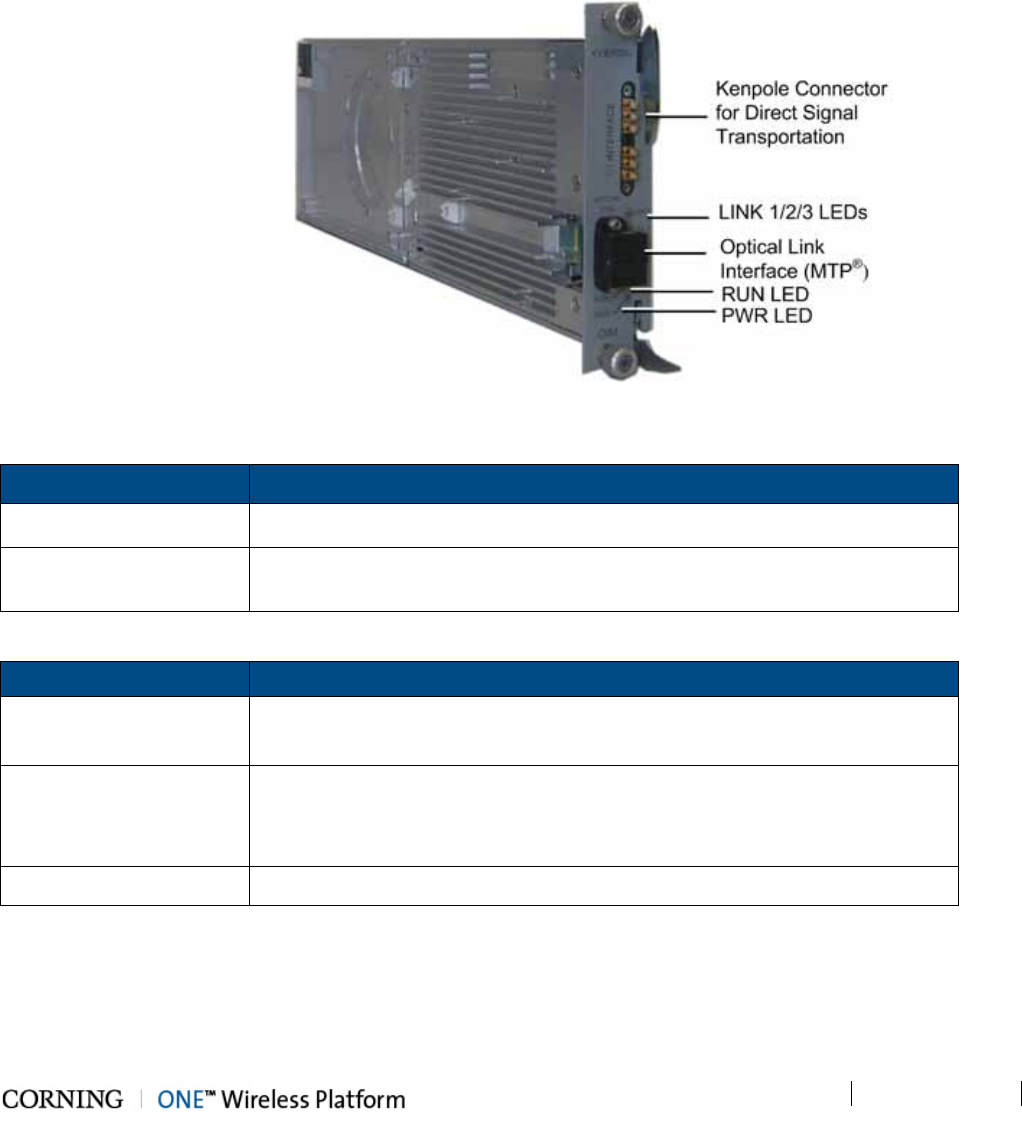
2.2.2 OIM (Optical Interface Module)
The OIM is a wideband RF to F/O (and vice-versa) media conversion module. Up to 12 OIM units can be installed in each OIU,
where each OIM can support up to three Remote Access Unit (RAU) connections.
Figure 2-10. Optical Interface Module
Port Description
OPTICAL LINK Female MTP® Connector for optical interface connection; SMF
1:1 INTERFACE Six Kenpole connector for 1:1 direct signal transportation, three UL and three
for DL Enables (DL and UL) broad band connection to each optical link
Table 2-9. OIM Ports Description
LED Description
Link 1-3 Steady Green - optical link power to/from the connected remote is normal
Blinking Green - optical power from remote is lower than required
RUN
Steady Green – OIM module SW has initialized and is up and running
Blinking Green - Fault detected
Off – Power off
PWR Steady Green – Input power detected in OIM
Table 2-10. OIM LED Descriptions
Unit Descriptions - RF Path P/N 709C011801 Page 43
DRAFT
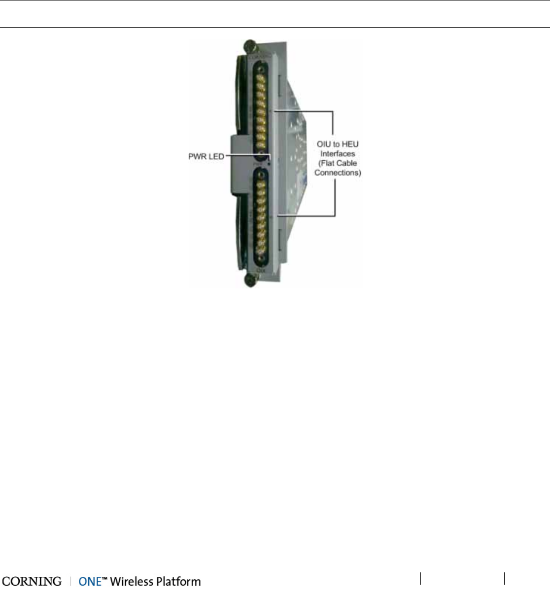
2.2.3 OIX (Optical Expander Module)
Each OIX Expander module provides the RF interface to up to two HEU units via two 9-pin connectors. Two OIX Expander
modules are installed in each OIU chassis. Up to four OIU units can be hosted by an HEU.
Note: The OIU Expander Modules are similar in appearance to the HEU Expander modules but are NOT
INTERCHANGEABLE. Each Expander module is indicated as RIX or OIX on the bottom of the module.
Figure 2-11. OIX Expander Module Interfaces
Unit Descriptions - RF Path P/N 709C011801 Page 44
DRAFT
2.3 RF Path Remote End Site Components
The RF coverage solution remote end components comprise the following elements:
• ICU (Intermediate Centralized Unit) - forwards optics along with DC to the RAU and its sub-modules.
• RAU (Remote Access Unit) - provides RF distribution and includes internal antennas. It can also encase data distribution
module (GEM).
• RxU (Remote Expansion Unit) - installed in the RAU. Provides support for two additional RF services for a total of 6 services
per RAU.
Figure 2-12. RF Path Remote End Components
A detailed description of the remote end components is provided in the following sections
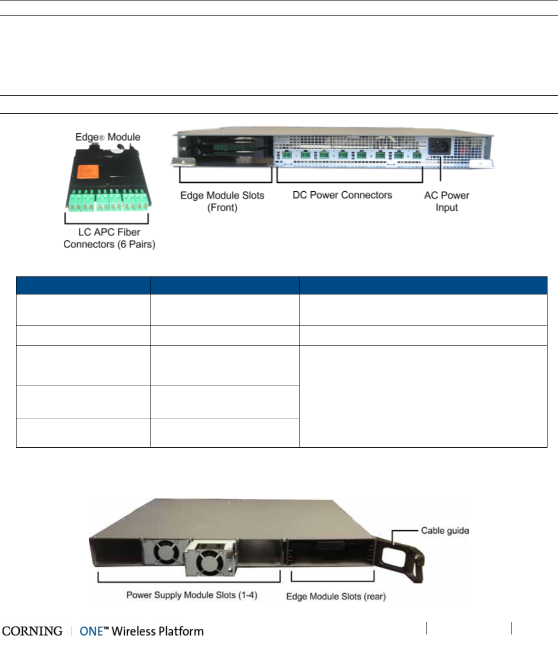
Unit Descriptions - RF Path P/N 709C011801 Page 45
DRAFT
2.3.1 ICU (Intermediate Centralized Unit)
Note: The ICU unit is common for the RF and Digital path components.
The ICU is installed at the floor level. It provides the LC APC optical interface along with DC power to the RAU RF (and data)
sub-modules. The optical and DC signals are routed via a composite cable connected between the ICU and hosted RAU
modules. The optics signal is provided via one or two dedicated Edge® modules that convert MTP optic interfaces to LC/APC
interface; the DC power is provided by up to four dedicated power supplies. A single power connection feeds all ICU power
supply modules.
Note: Pretium EDGE® Module – MTP® to LC APC splice module/cassette/field-term cassette
Figure 2-13. ICU Front Panel Interfaces and Modules
Chassis/Module Interface Description
ICU Chassis Power Connectors Up to eight DC power connectors, depending on
number of power supply modules installed.
PSM AC Power Input 110-240 V AC power input to unit
Edge® Module LC APC SM Optic connectors implemented by up to two Edge®
modules inserted from the rear: six connectors per
Edge® module.
MTP® SM fiber port
Edge® Splice Cassette LC APC to a (twelve x 250µm
single fiber) pigtail
Edge® Field-Term Cassette LC APC to LC APC
Table 2-11. ICU Front Panel Interface Descriptions
Edge® modules and power supplies are extracted and inserted from the rear of the unit.
Figure 2-14. ICU Rear Panel Interfaces and PSM Modules
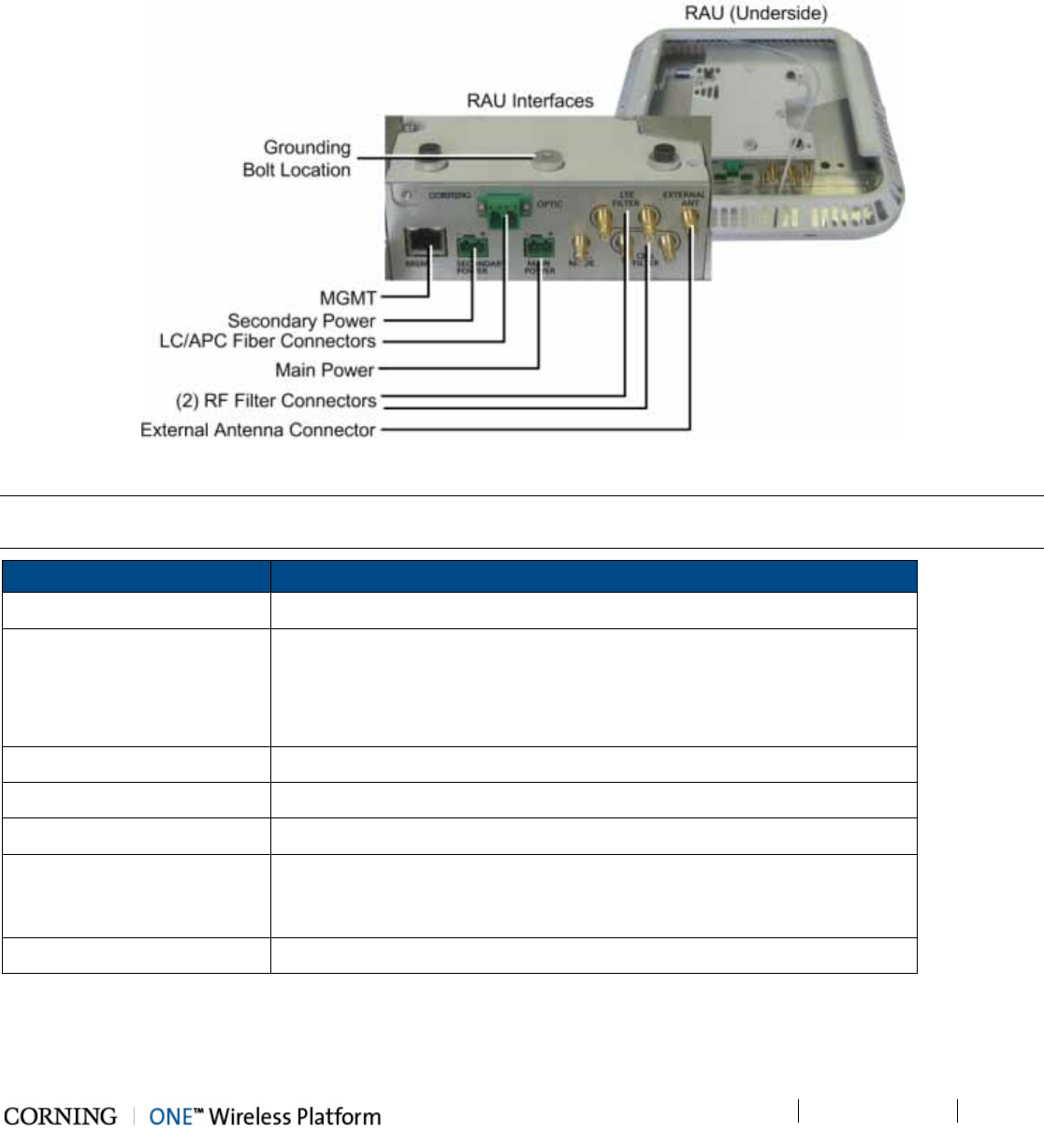
Unit Descriptions - RF Path P/N 709C011801 Page 46
DRAFT
2.3.2 RAU (Remote Access Unit)
The RAU distributes up to four RF services via internal antennas (external antennas are optional). The RF services are received
over optic cables and converted for distribution over internal (or optionally, external) antennas.
Figure 2-15. RAU Module Interfaces
Note: The RAU enclosure can host two additional modules: RxU for MIMO support (e.g. LTE700 and AWS) and GEM for digital
coverage. See relevant sections for details on these modules.
Interface Description
MGMT RJ-45 local management connection
PWR
DC power inputs
Main - connect to DC (from composite cable)
Secondary – in case of PoE clients. Used when GEM modules are installed
(in addition to Main)
F/O LC APC SM connectors for UL and DL optic connections
Listening Mode N/A
RF Filter (e.g. LTE, CELL) QMA RF ports for external cavity filter use (In/Out). For CELL and LTE filters.
External Antenna
Optional connection to broadband external antennas. Antenna must have a
return loss of 12dB. Requires GUI configuration (internal antenna is enabled
by default).
Grounding Bolt Location Use the 8-32X3/8 bolt (supplied with RAU) to connect RAU to earth ground
Table 2-12. RAU Interfaces
The RAU status LEDs are located on the top left (see Figure 2-16).
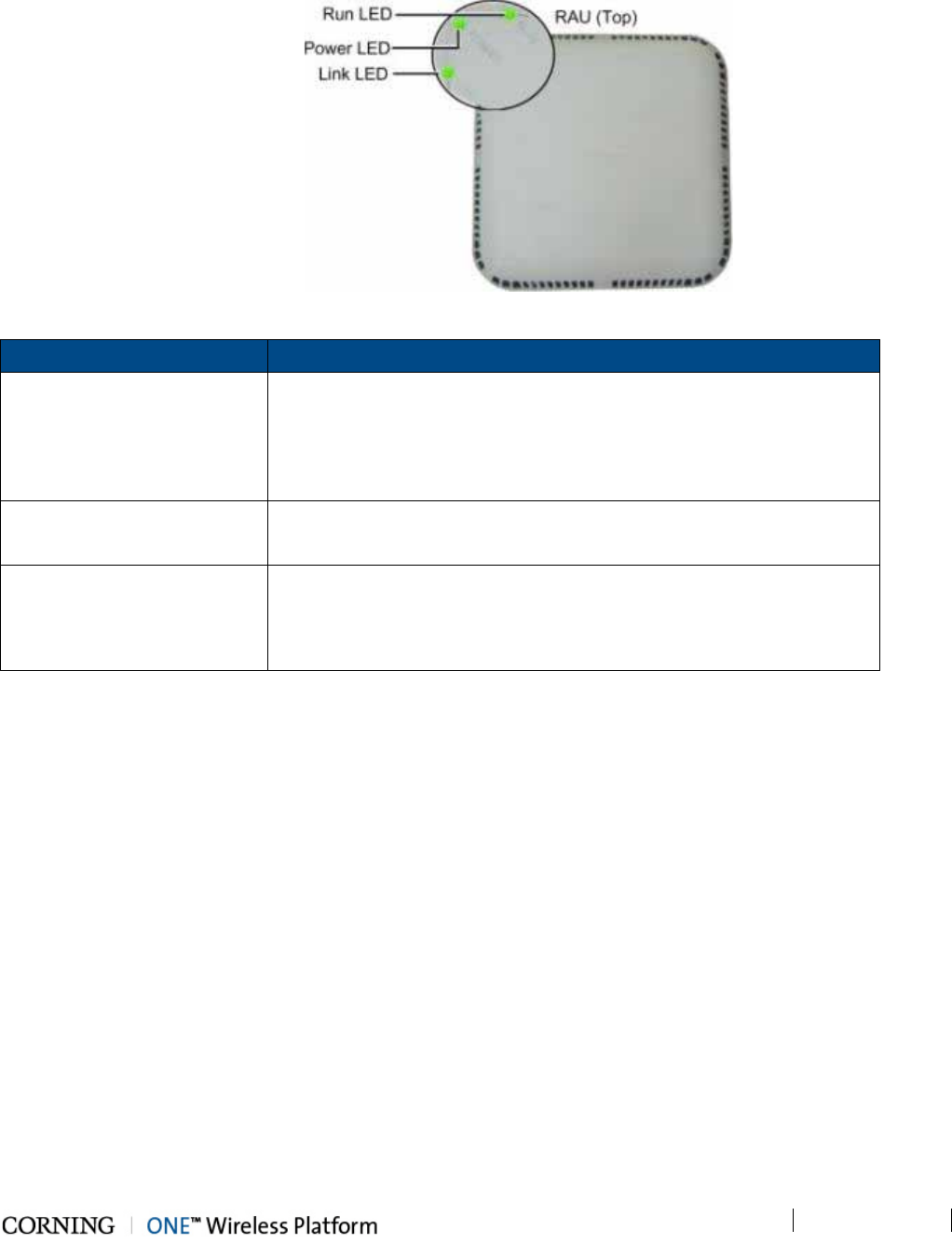
Unit Descriptions - RF Path P/N 709C011801 Page 47
DRAFT
Figure 2-16. RAU LEDs
LED Description
RUN Blinking Green Blinking – RAU Initializing
Steady Green – RAU boot up sequence complete and module SW up an
running
Off – No power supplied to unit
POWER Steady Green - Power input detected by RAU
Off - No power supplied to RAU
LINK Steady Green – Optical link power to/from the RAU is normal
Blinking green – Optical power from remote is lower than required
Off – No optical link is detected
Table 2-13. RAU Status LEDs Description
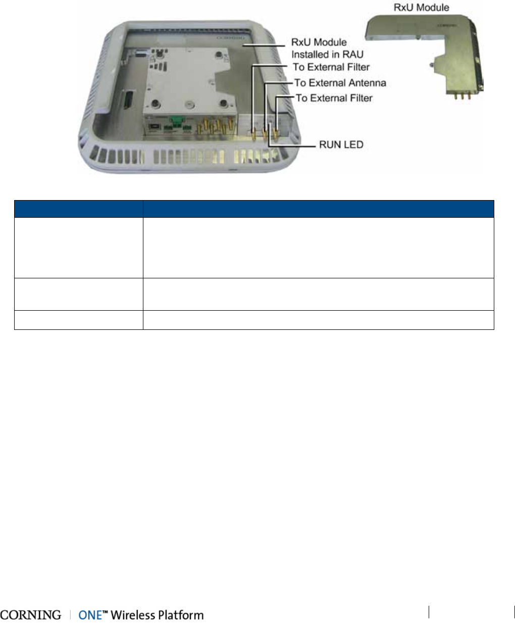
Unit Descriptions - RF Path P/N 709C011801 Page 48
DRAFT
2.3.3 RxU (Remote Expansion Unit)
The RxU is an Add-on to the RAU which provides support for MIMO services (i.e. 700MHz LTE, AWS).
Figure 2-17. RxU Interfaces
Module Description
External Antenna
RF Connection to external antenna, used for above-ceiling installation.
Antenna must have a return loss of 12 dB.
(Both the RxU and the RAU antennas are used since this implements a
MIMO configuration)
External RF Filters QMA RF ports for external cavity filter use (if required by site planner). For
CELL and LTE filters.
RUN LED Indicates SW is up and running.
Table 2-14. RxU Front Panel Interface Connections
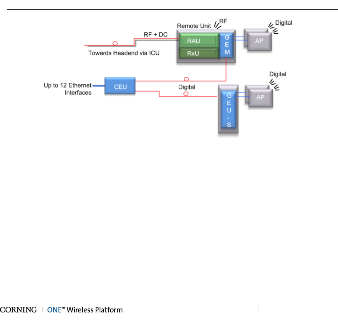
Unit Descriptions - Digital Path P/N 709C011801 Page 49
DRAFT
3 Unit Descriptions - Digital Path
This chapter provides detailed descriptions of the Digital Path components.
3.1 Digital Path Components
The digital path comprises the following elements - located at the remote end
• CEU – Centralized Ethernet Unit
• GEU-S – Standalone Gigabit Ethernet Unit
Note: The GEM module can also be installed in the RAU enclosure so that the RAU provides both RF and digital services.
Figure 3-1. ONE™ Digital Path Architecture
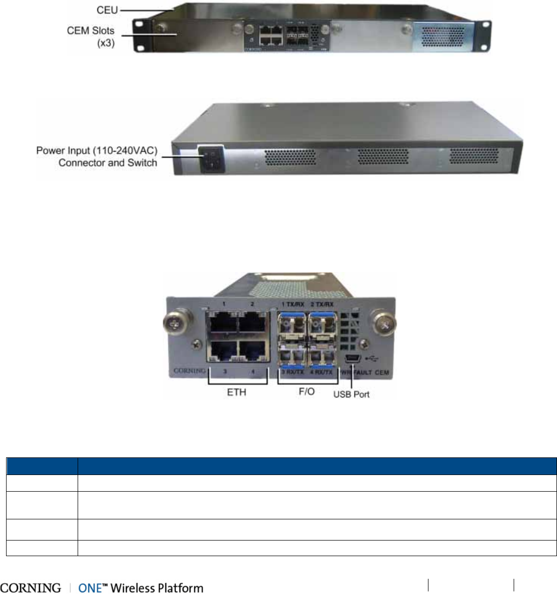
Unit Descriptions - Digital Path P/N 709C011801 Page 50
DRAFT
3.2 CEU (Centralized Ethernet Unit)
The CEU is a Centralized Ethernet-over-Fiber media and rate converter unit. Located at the remote end, it converts Ethernet
media (from a LAN switch) to fiber media for routing towards GEM modules. The CEU hosts three Centralized Media Converter
Modules (CEMs).
Figure 3-2. CEU Front Panel with Installed CEM Module
Figure 3-3. CEU Rear Panel
3.2.1 CEM (Centralized Ethernet Module)
The CEU supports up to three CEM modules, where each CEM supports four Ethernet ports (LAN switch connections) and four
F/O connectors (towards GEM modules). All interfaces (except for power) are located on the front panel.
Figure 3-4. CEM Interfaces (Installed in CEU)
The CEM module interfaces include Ethernet connections to the Ethernet switch, F/O connections and LED status indicators.
The following table provides a description of the CEM ports.
Port Description
ETH Four 10/100/1000BASE-T RJ-45 connectors (LAN switch connections) to four LC UPC fiber connectors
F/O Four 10/100/1000BASE-T Copper ports to four LC UPC fiber connectors (using SFP –small-form
pluggable module) towards GEM modules
USB port USB serial port - service port
PWR Steady Green – Power input detected for corresponding module
Table 3-1. Ports Description
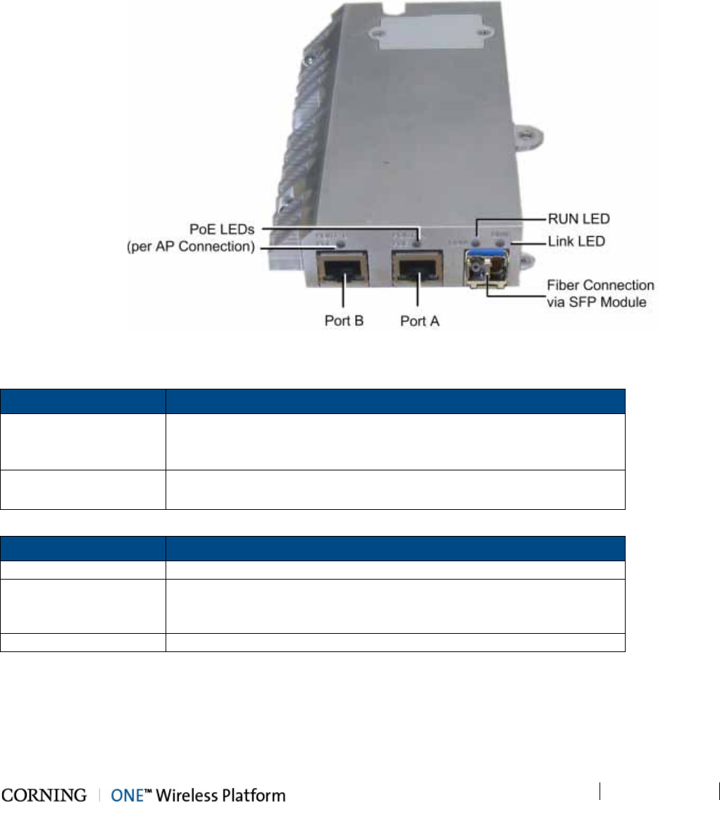
Unit Descriptions - Digital Path P/N 709C011801 Page 51
DRAFT
3.3 GEM (Gigabit Ethernet Module)
The GEM converts the received optical signal to two Ethernet digital connections, which are then routed along with PoE to two
remote access points. The GEM module can be installed in the following configurations:
• Installed in RAU - as an optional plug-in module (see section 5.2.2)
• As a standalone module (GEU-S) - (see section 6.2)
Figure 3-5. GEM Interfaces
Table 3-2 and Table 3-3 provide descriptions of the ports and LED indicators.
Port Description
PORT A/PORT B
Two 10/100/1000Base-T copper interface with 802.3at compliant Power
over Ethernet (PoE+) PSE ports capability for connections to remote
access points
FC APC One 1000BASE-X T Copper port to LC UPC fiber connectors (using
SFP –small-form pluggable module) towards CEM module
Table 3-2. GEM Port Interfaces
LED Description
PoE (PORT A/PORT B)
Indicates power supplied to connected AP
LINK
Steady Green - the optical link to/from the connected remote functions
within the specifications in both directions.
Blinking Green - optical power from remote is lower than required
RUN Steady Green – GEM module SW is up and running
Table 3-3. GEM LED Indicator Descriptions
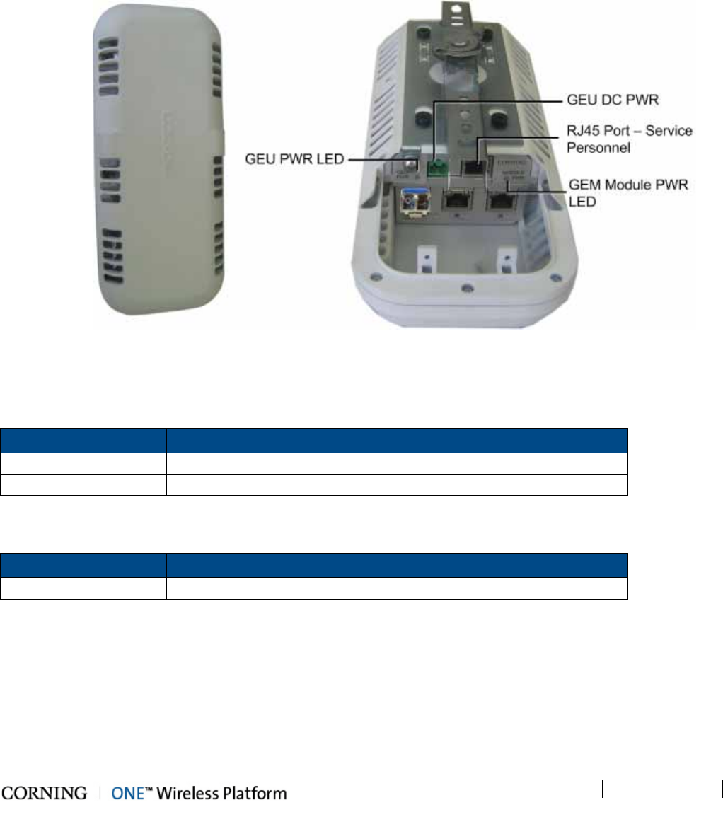
Unit Descriptions - Digital Path P/N 709C011801 Page 52
DRAFT
3.4 GEU-S (Standalone Gigabit Ethernet Unit)
The GEU-S is a GEM Standalone unit and includes the mounting option and DC power supply for the GEM module. See 6.2 for
details on the installation procedure. Allows for the GEM to perform media conversion services from Fiber to Copper and to
supply PoE and PSE services
Figure 3-6. GEU Enclosure: Top (Left) and Open Underside (Right)
Table 3-4 and Table 3-5 provide descriptions of the ports and LED indicators for the GEU module of GEU-S unit. Refer to
section 3.3 for the GEM module ports and LED descriptions.
Port Description
DC Power Connector Connector for DC wire pairs (42-57 V DC)
Ethernet RJ-45 port used for Ethernet connection
Table 3-4. GEM Port Interfaces
LED Description
GEU PWR Steady Green – Power input detected in GEU module
Table 3-5. GEU LED Indicator Descriptions

Installation Guidelines P/N 709C011801 Page 53
DRAFT
4 Installation Guidelines
The following installation assumes that site survey and installation planning (including power requirements) have been
completed. This includes planning the distribution of antennas to provide the required coverage, as well as planning the layout
of the devices and cables in the telecom closet or shaft.
4.1 Infrastructure Preparation
The following installation rules are based on the assumption that the site survey and installation planning (including power
requirements) have been completed.
4.2 Installation Requirements
The infrastructure preparation consists of two main phases:
A. Floor Planning: Planning the distribution of the Remote Access Units (RAUs) on each floor to provide the required
coverage.
B. Telecom Closet Planning: Planning the layout of the devices and cables in the telecom closet or shaft. This includes all
cabling and other voice service and digital coverage distribution systems that are relevant to the specific installation.
4.3 Safety Guidelines
Before installing the equipment review the following safety information:
• Follow all local safety regulations when installing the equipment.
• Only qualified personnel are authorized to install and maintain the Repeater.
• Ground specified equipment with the provided grounding bolt
• Do not use the grounding bolt to connect external devices.
• Follow Electro-Static Discharge (ESD) precautions.
• Use low loss cables to connect the antennas
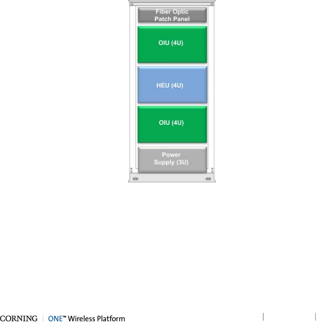
Installation Guidelines P/N 709C011801 Page 54
DRAFT
4.4 Rack Installation Guidelines
These guidelines are relevant to the system components which are installed in 19-inch communication racks: RF Path
components: HEU, OIU and ICU; Digital Coverage components: CEU
• Verify that the rack height can support all the units to be installed, where you may also want to consider future installations.
Figure 4-1 shows an example of a rack configuration for the RF path components at the headend which facilitates and
simplifies the cabling connections.
• The configuration is for a single operator. If the site is serviced by more than one operator, each operator often installs their
equipment in a separate rack. Refer to section 0 for 4x4 HEU-OIU rack installation configurations (maximum configuration
including four HEU and four OIU units).
Figure 4-1. Example of Communication Rack Installation
4.4.1 Rack Safety Instructions
The following guidelines are relevant to the rack installed units. Review the following guidelines to help ensure your safety and
protect the equipment from damage during the installation.
• Only trained and qualified personnel should be allowed to install or replace this equipment.
• Verify that ambient temperature of the environment does not exceed 50°C (122° F)
• To maintain a low center of gravity, ensure that heavier equipment is installed near the bottom of the rack and load the rack
from the bottom to the top.
• Ensure that adequate airflow and ventilation within the rack and around the installed components so that the safety of the
equipment is not compromised. It is recommended to allow for at least about 2 cm of airspace between devices in the rack.
• Verify that the equipment is grounded as required – especially the supply connections.

Installation Guidelines P/N 709C011801 Page 55
DRAFT
4.5 Power Requirements
This section summarizes the power requirements of all ONE™ RF and digital coverage devices.
4.5.1 Power Safety Instructions
SAFETY WARNINGS!!!! When installing or selecting the power supplies:
• Use only the power cables (AC and DC) and any other relevant accessories provided with the unit to connect the power
supply to the ONE™ units.
• Be sure to disconnect all power sources before servicing.
• Calculate the required power according to the requirements of the specific installation and then determine the configuration
of the power supplies. The required DC cables will then be determined by the selected PS configuration.
• Use only UL approved power supplies
• Install external over-current protective devices for the system according to the requirements described in section 1.3.3 -
Power .
• For GEU-S units – 3rd party equipment (PoE clients) intended for connection to the PoE outputs must meet the “Resistance
to Fire” requirement (clause 4.7) of the IEC/EN/UL60950-1 standard.
4.5.2 Types of Power Supplies
CMA supplies various power supplies that can be installed in a rack or mounted on a wall, depending on your configuration.
4.5.3 Circuit Breakers
Calculate the required fuse protection while referring to section 1.3.3 - Power . Also, when Install fuse protections for the system
taking into account that there may be other CMA system elements that require external fuse protection.

Installation Guidelines P/N 709C011801 Page 56
DRAFT
4.6 RF Coaxial Cable Guidelines
4.6.1 General Cable Installation Procedures
Note: The installer should be familiar with the ANSI/TIA/EIS-568 Cabling Standard guidelines.
Observe the general cable installation procedures that meet with the building codes in your area. The building code requires
that all cabling be installed above ceiling level (where applicable). The length of cable from the risers to each antenna must be
concealed above the ceiling.
The cable must be properly supported and maintained straight using velcro cable ties, cable trays and clamps or hangers every
10 feet (where practical above ceiling level). Where this is not practical, the following should be observed:
• The minimum bending radius of the supplied ½” coax cable should be 7”.
• Cable that is kinked or has a bending radius smaller than 7” must be replaced.
• Cable runs that span less than two floors should be secured to suitably located mechanical structures.
• The cables should be supported only from the building structure.
• All cables shall be weather-resistant type.
• Cable length - determined by the system installation plan. When calculating the cable length, take into account excess cable
slack so as not to limit the insertion paths.
4.6.2 RF Rules
• Use coax RG-223, 50ohm, male-to-male N-type to QMA for RF connections from the RIMs to the BTS/RBS and to the
RAUs.
• When using the Corning system in an environment in which other indoor coverage systems are installed, it is recommended
(where possible) that the antennas are placed at least two meters apart
• When bending coax cables, verify that the bending radius does not exceed the coax specifications.
• Use a VSWR meter (i.e. Site Master or equivalent) for checking coax cables, including the antennas. (<2). The VSWR must
be measured prior to terminating the RAUs at the remote locations

Installation Guidelines P/N 709C011801 Page 57
DRAFT
4.6.3 Coax Cable Lengths and Losses
Use coax ½”, 50ohm, male-to-male QMA type, for connecting to RAU and external antenna ports.
Note: The required distance between the antennas (installed in the ceiling) depends on the infrastructure and calculated
path-loss. For example, if there is free space-loss between the antennas, a minimum distance of 100 ft is required; if
there are partitions (loss) between the antennas, a distance of less than 100 ft between them is allowed.
Coax Length
Coax Loss
(900 MHz)
Connector
Loss
Total Loss
30 0.7 1.5 2.2
40 0.9 1.5 2.4
50 1.1 1.5 2.6
60 1.3 1.5 2.8
70 1.5 1.5 3
80 1.7 1.5 3.2
90 1.9 1.5 3.4
100 2.1 1.5 3.6
110 2.3 1.5 3.8
120 2.5 1.5 4
130 2.7 1.5 4.2
140 2.9 1.5 4.4
150 3.1 1.5 4.6
160 3.3 1.5 4.8
170 3.5 1.5 5
180 3.7 1.5 5.2
190 3.9 1.5 5.4
200 4.1 1.5 5.6

Installation Guidelines P/N 709C011801 Page 58
DRAFT
4.7 Antenna Specifications and Guidelines
Determine the antenna installation configuration, according to the transmission and coverage requirements and the installation
site conditions.
4.7.1 Authorized Antennas and Required Specifications
• ONE™ RAU (Remote Access Unit) is equipped with an Omni Directional integrated antenna; 0 dBi (15 deg. down from
horizon)
• External antennas - No limitation on any vendor of available external antennas with respect to the following requirements:
• Omni Directional or Directional
• Supported frequency range: wideband antennas supporting a range of 700 MHz to 2600 MHz
• Gain: up to 12.5 dBi
• Impedance: 50 Ohm
• Return Loss: +12 dB
• Number of antennas that can be connected (with cables/splitters) – it is not recommended to connect more than one
antenna per connector since 1:1 connectivity is reduced with each split.
• Types of couplers/splitters – depends on number of splits (not recommended)
4.7.2 General Installation Guidelines
• The RAU should be installed at a convenient location, free of metallic obstruction (can also be installed in plenum spaces).
• Install the RAU at the designated height and tune it roughly toward the Service coverage area.
• Installation of this antenna must provide a minimum separation distance of 20 cm from any personnel within the area.
• Cable and jumper loss is at least 2 dB.
Installation Guidelines P/N 709C011801 Page 59
DRAFT
4.8 Fiber Optic Requirements
4.8.1 Authorized Optic Cables
The following specified optic cables are authorized for use with ONE™ products:
Vertical
Horizontal
Plug & Play™ Plenum Optical cables
MTP Fiber Connectors
12 – 144 fibers
2-sided or 1-sided
Armored, non-armored
Composite Plenum Tether Assemblies
Fiber: LC APC, 2 – 24 fibers
Cu: 16AWG, 14AWG, 12AWG; 2 – 12 Conductors
Armored, non-armored
4.8.2 Fiber Optic Rules
• Use only MTP® or LC APC connectors
• UniCam connectors can be used for field termination
• Use only fusion splice for connecting two fibers
• Use minimum splicing/connectors to achieve minimum losses on the fibers (< 0.5 dB)
• Use precaution while installing, bending, or connecting fiber optic cables:
• Fiber optic cable is sensitive to excessive pulling, bending and crushing forces. Consult the cable specification sheet for
the cable you are installing.
• Do not bend cable more sharply than the minimum recommended bend radius.
• Do not apply more pulling force to the cable than specified.
• Do not crush the cable or allow it to kink. Doing so may cause damage that can alter the transmission characteristics of
the cable. The cable may have to be replaced.
• Use an optical power meter and light source for checking the fiber optic cables
• Make sure the environment is clean while connecting/splicing fiber optic cables
• All fiber optic connectors should be cleaned prior to connecting to the system
• Fiber connector protective caps should be installed on all non-terminated fibers and removed just before they are
terminated.
• Pay special attention while connecting the MTP® and/or LC APC connectors – ensure that you hear a “click”, indicating a
secure connection
• Never look directly into the end of a fiber that may be carrying laser light. Laser light can be invisible and can damage your
eyes.
Installation Guidelines P/N 709C011801 Page 60
DRAFT
4.9 Power Safety Instructions
SAFETY WARNINGS
• When installing or selecting the power supplies:
• Be sure to disconnect all power sources before servicing.
• Calculate the required power according to the requirements of the specific installation and then determine the configuration
of the power supplies. The required DC cables will then be determined by the selected PS configuration.
• Use only UL approved power supplies
• AC and DC power supply cables – only use the power cords supplied with the units
• Install external over-current protective devices for the system according to the requirements described in section 1.3.3.
Types of Power Supplies
Corning supplies various power supplies that can be installed in a rack or mounted on a wall, depending on your configuration.

Installation – RF Path Elements P/N 709C011801 Page 61
DRAFT
5 Installation – RF Path Elements
This chapter describes the installation of the RF path components. For specific guidelines on infrastructure planning, design
and installation, please consult with a Corning Product Line Manager or Corning approved Installer.
5.1 Headend Elements
The (RF coverage) headend site installation consists of installing the HEU and OIU units.
Note the following information (for both HEU and OIU units):
• The chassis and modules are supplied separately and must be inserted by the user. Only the fan module is factory installed
in the HEU/OIU chassis rear.
• The HEU and OIU units are installed at the IDF (Intermediate Distribution Frame), adjacent (or as close as possible) to each
other to facilitate the connections. See section 5.1.2.2 for an optimal 4x4 HEU-OIU rack configuration – in terms of location
in rack where each OIU is connected to each HEU.
• The ERFC cable (Expander Cable interconnecting the (OIU) OIX and (HEU) RIX modules) are provided in lengths ranging
from 16 to 59 in so as to accommodate a range of HEU-OIU rack installation configurations.
• Hot-swappable modules: RIM (RF Interface Modules) and Power Supply(ies), Fan Modules and RIX/OIX (HEU/OIU
Expander Modules). HCM, ACM modules are not hot-swappable.
• If a redundant power supply is provided, both supplies must be installed, connected to respective AC or DC power and
switched on.
• The 4x4 configuration includes four HEU units connected to four OIU units. This is the maximum number of headend units
that can be managed by a single HCM.
• The components of each system installation are control and managed via a single HCM which is installed in an HEU chassis.
In configurations with more than one HEU chassis, the HEU installed with an HCM module serves as the “Main” HEU,
whereas each additional HEU unit (Auxiliary) is installed with an ACM (see section 5.1.1).
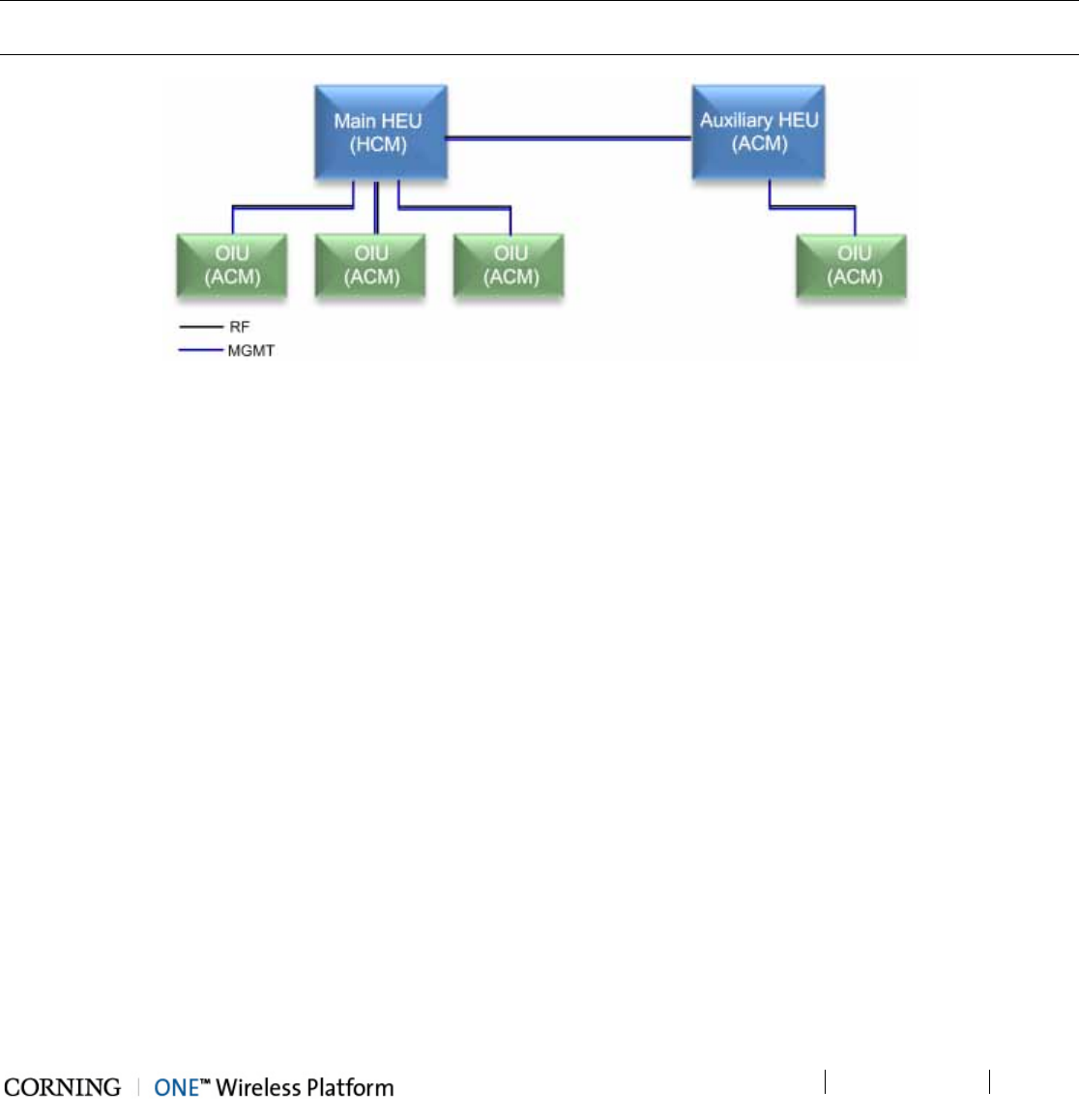
Installation – RF Path Elements P/N 709C011801 Page 62
DRAFT
5.1.1 HEU Main and Auxiliary Configurations
In a configuration with more than one HEU chassis, one HEU (Main) is installed with an HCM module whereas, the additional
HEU units (Auxiliary) are installed with ACM modules, enabling single source management of the ONE™ Wireless Platform
from a single HCM. Figure 5-1 provides an example of the management and RF connections between the Main and Auxiliary
HEU chassis and connected OIUs.
Each OIU is connected to its host HEU through two connections: MGMT (ETH to INTERNAL port) and RF (RIX/OIX ports). For
standalone configurations, up to four OIU chassis can be connected to an HEU.
Note: The maximum configuration is a 4x4 configuration including four HEU connected to four OIU (see section 5.1.2.6 for
RIX-OIX connections; see 0 for management connections).
Figure 5-1. Example of Management and RF Connections for Main and Auxiliary HEU Units
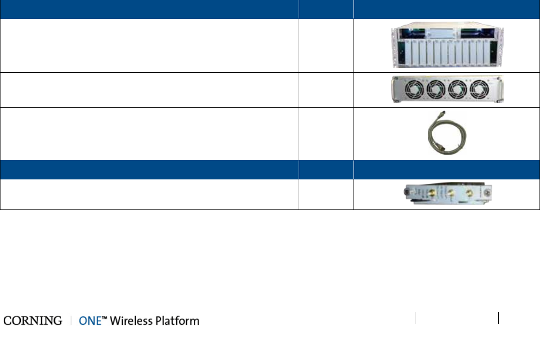
Installation – RF Path Elements P/N 709C011801 Page 63
DRAFT
5.1.2 HEU Installation
Note the following information:
• The HEU chassis is supplied empty and only includes the factory assembled FAN Module (FAM). All other modules are
ordered separately and must be installed.
• The RF service interfaces are implemented by service specific RIM/RIM-M modules that are provided separately according
to your order.
• In installations with more than one HEU, the HEU in which the HCM module is installed is determined as the “Main HEU”.
Any additional HEU unit is installed with an ACM module and is managed via the HCM in the Main HEU through an
RJ45/RJ45 connection (see section 5.1.1).
• One HEU supports connections to up to four OIU units
• The Cable management Tray can be assembled either before or after the unit is installed (see section 5.1.4 - HEU/OIU
Cable Management Tray).
5.1.2.1 Unpacking and Inspection
This section describes the installation procedure for the ONE™ Headend Unit (HEU) and relevant modules.
Unpack and inspect the cartons according as follows:
6. Open the shipping cartons and carefully unpack each unit from the protective packing material.
7. Verify that all the items required for installing the ONE™ HEU according to the items listed in Table 5-1. If any of the listed
items are missing, contact your Corning Cable Systems representative.
8. Check for signs of external damage. If there is any damage, call your Corning Cable Systems representative.
Items required for installing the HEU:
HEU Kit
Quantity
Item
Headend Unit Chassis (with blank panels on RIM and one PSM slots
)
– includes factory installed Fan Module (FAM) in chassis rear
1
Fan Module (FAM) – single unit hosting 4 fans
(factory installed in chassis rear)
1
RJ45/RJ45 communication cable L=2m-2.15m (P/N 705900003) –
HCM management cable
1
RIM Kit (1-12 according to order)
Quantity
Item
Radio Interface Module (service specific) 1
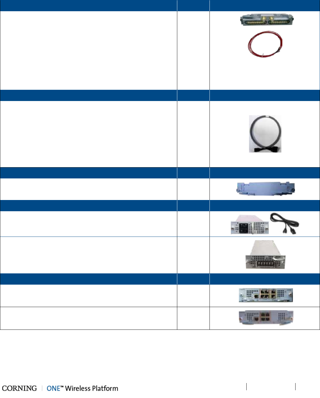
Installation – RF Path Elements P/N 709C011801 Page 64
DRAFT
RIX Module Kit (1 or 2 according to order)
Quantity
Item
Radio Expander Module – expands the RF sources to the OIU 1
Item
Pilot Transport Cable (P/N: PCKC47*) – Single QMA to QMA cable;
L = 47 in; used for passing reference clock signal connections
between RIX modules.
*Additional lengths can be ordered:
• PCKC20: L=20 in
• PCKC63: L=63 in
• PCKC79: L=79 in
1
ERFC Cable Kit (according to order)
Quantity
Item
ERFC (Expander Cable) - RF interface cable to HEU; 9 pin SMP to
SMP connector
Available in five different lengths:
• ERFC16: L= 16 in
• ERFC24: L= 24 in
• ERFC34: L= 34 in
• ERFC40: L= 40 in
• ERFC59: L= 59 in
1
ETM Kit (according to order)
Quantity
Item
ETM Expander Termination Module (for unoccupied Expander slot) 1
PSM Kit (AC or DC modules - 1 or 2 kits according to order)
Quantity
Item
PSM-AC: 100-240 VAC Power Supply Module including s
tandard
IEC 60320-1 C13 cable
1
PSM-DC: 48 V DC Power Supply Module; 9 A Max.; six pin DC input
terminal block connector
; includes six terminal rings used for
crimping onto the DC wires
1
Controller Module Kit (HCM or ACM - according to order)
Quantity
Item
HCM Kit (Headend Control Module) –
installed in Main HEU unit;
enables remote/local management of all hosted units
1
ACM Kit (Auxiliary Control Module) – installed in Auxiliary HEU units;
provides management connections for the Auxiliary HEU.
1
Table 5-1. Items Required for HEU Installation
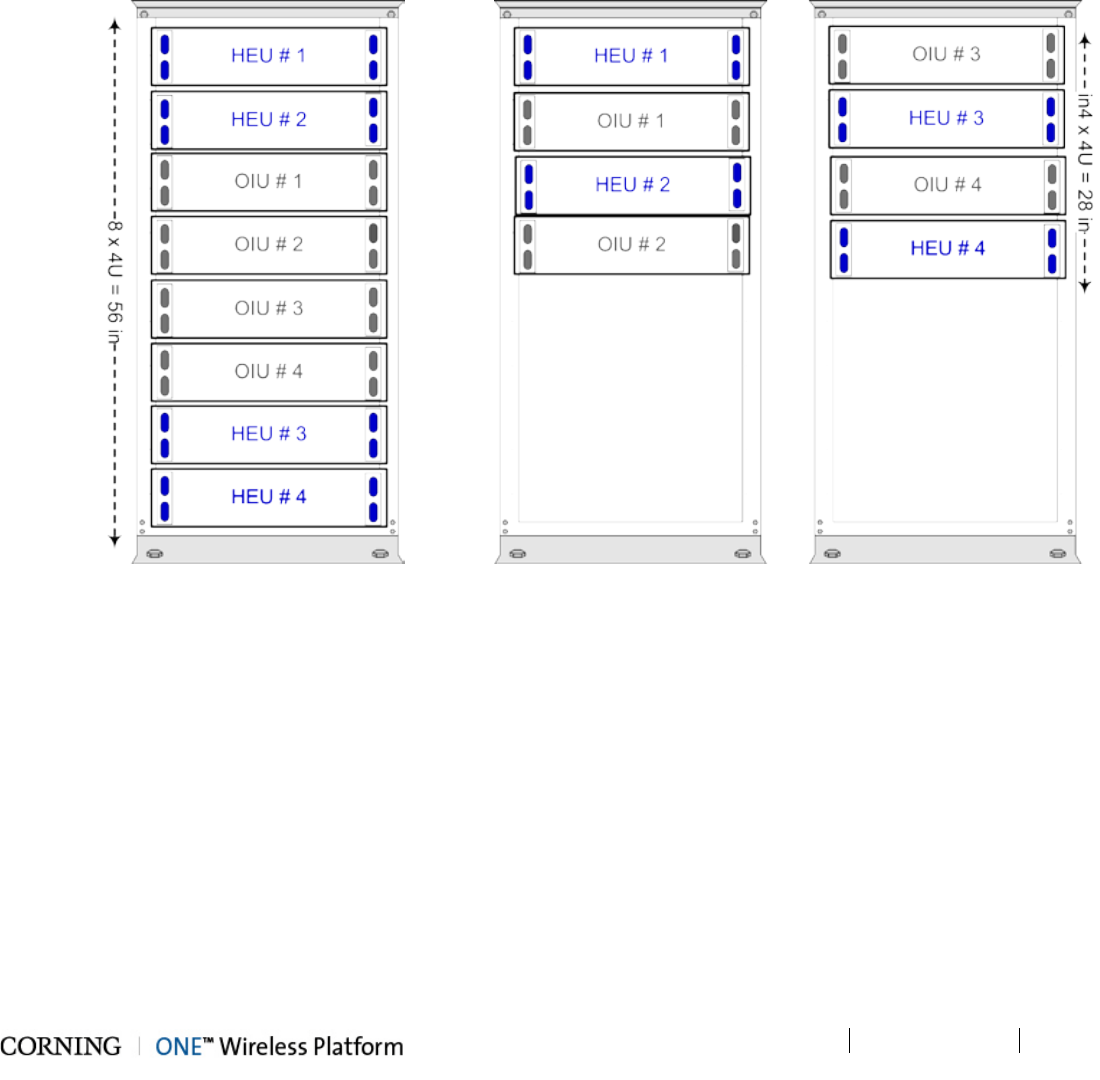
Installation – RF Path Elements P/N 709C011801 Page 65
DRAFT
5.1.2.2 Mounting the HEU Chassis
Note the following:
• HEU chassis requires 4U rack height availability
• Rack nuts and screws not provided (depend on rack type)
To mount the HEU chassis (in 19-in rack)
1. Determine the location of the HEU in the rack while considering additional HEU and OIU units and the lengths of the
available ERFC cables. Figure 5-2 and Figure 5-3 illustrate the optimal rack installations for a maximum 4x4 HEU-OIU
configuration in shared and dedicated equipment scenarios.
Figure 5-2. 4x4 Installation Diagram – Dedicated Figure 5-3. 4x4 Installation Diagram – Shared
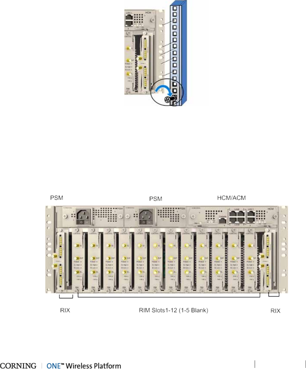
Installation – RF Path Elements P/N 709C011801 Page 66
DRAFT
2. Referring to Figure 5-4 secure the units’ rack ears to the rack frame as follows:
• Insert two screws half-way into the rack frame.
• Position the chassis on to the screws using the handles and the top and bottom half slots of the rack ears.
• Secure the unit in the rack via all applicable bracket holes using the appropriate rack nuts and screws.
Figure 5-4. Installing Chassis in Rack
5.1.2.3 Installing all Modules
Note that for modules with ejectors (i.e. RIM, RIX and HCM/ACM) – verify that the ejectors are completely open when inserting
in dedicated slot and then push in until the module clicks in to the backplane. Figure 5-4 shows example of module type captive
screws and ejectors.
To install the HEU modules:
3. Refer to Figure 5-5 for module locations. Remove blank panel and slide in the relevant module (chassis slots are 100%
mistake proof) as shown in Table 5-2 :
Figure 5-5. Example of occupied HEU
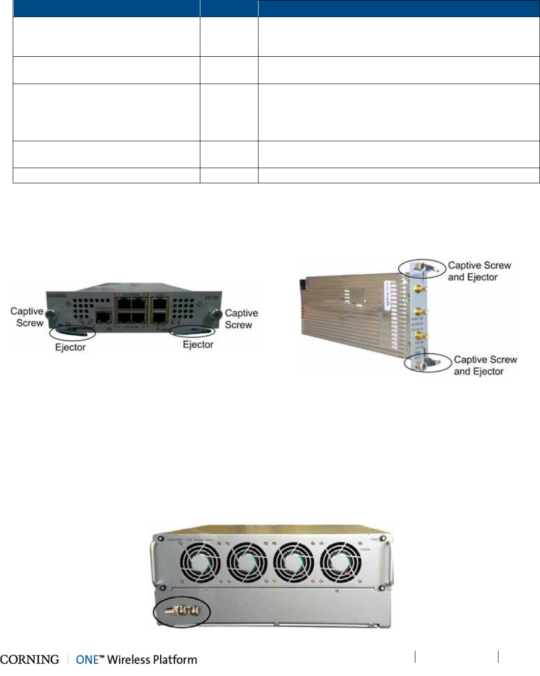
Installation – RF Path Elements P/N 709C011801 Page 67
DRAFT
Module
Quantity
Comment
HCM (for Main HEU units) 1 In installations with more than one HEU, the HCM is installed in
one of the chassis which will be referred to as the “Main” HEU;
One HCM per system installation.
ACM (for Auxiliary HEU units) 1 Installed in the HEU in configurations consisting of more than
one HEU chassis
PSM 1 - 2 • For installations with one PSM module – install module in
left most slot
• For installations with two PSM modules – remove blank
panel from middle slot and insert additional PSM module
RIX 1 - 2 In installations with only one RIX, the unoccupied RIX slot must
be terminated with an ETM.
RIM 1 - 12 No need to terminate unoccupied RIM slot – leave blank panel
Table 5-2. Modules Required for HEU Installation
4. Referring to examples of modules shown in Figure 5-6 and Figure 5-7 secure the modules to the backplane by:
• Closing the ejectors (for relevant modules)
• Tightening the captive screws
Figure 5-6. HCM Ejectors and captive Screws Figure 5-7. RIM Ejectors and captive Screws
5.1.2.4 Grounding HEU Chassis
The grounding connection is performed via a two-hole, standard barrel grounding lug located on the HEU rear panel (see
Figure 5-8):
• For use with stranded copper wire conductors
• 10-14 AWG
• Holes - 1/4 inch
Figure 5-8. Grounding lug (HEU Chassis Rear)
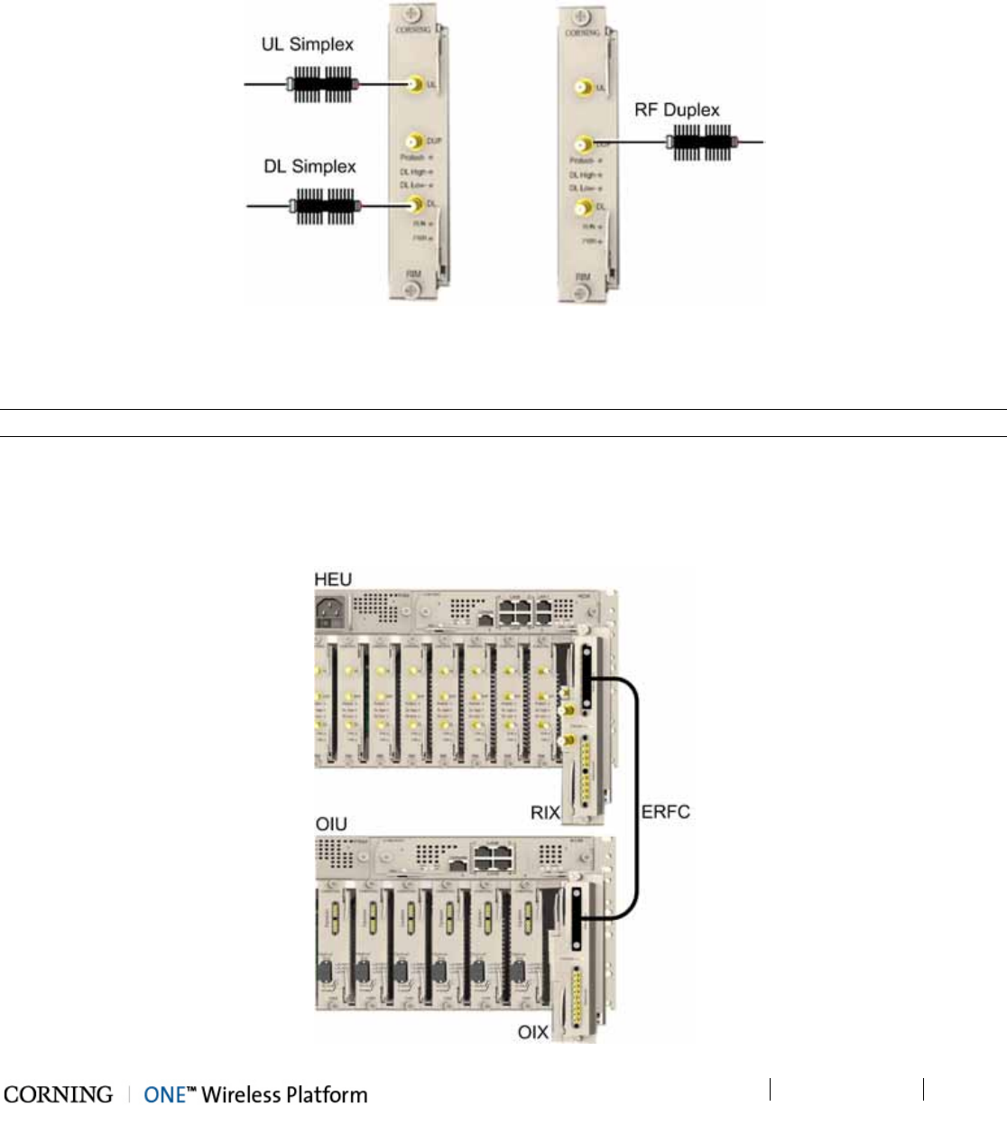
Installation – RF Path Elements P/N 709C011801 Page 68
DRAFT
5.1.2.5 RIM Connections to RF Source
For each service specific RIM - connect (Simplex or Duplex) RF QMA connectors to the service providers’ external RF source.
See Figure 5-9.
Figure 5-9. RIM RF Source Interfaces
5.1.2.6 RIX to OIX Connections
Note: Each RIX module supports connections to up to two OIUs.
Using the appropriate length ERFC cable (according to distance of available OIX port) connect the HEU RIX module 9-Pin
connector to the corresponding connector on the OIU OIX module. See Figure 5-10.
Refer to Section 5.1.2.7 for schematic diagram of coax connections in a maximum HEU-OIU configuration of 4x4 where all HEU
units are connected to all OIU units.
Figure 5-10. HEU to OIU Coax Connections
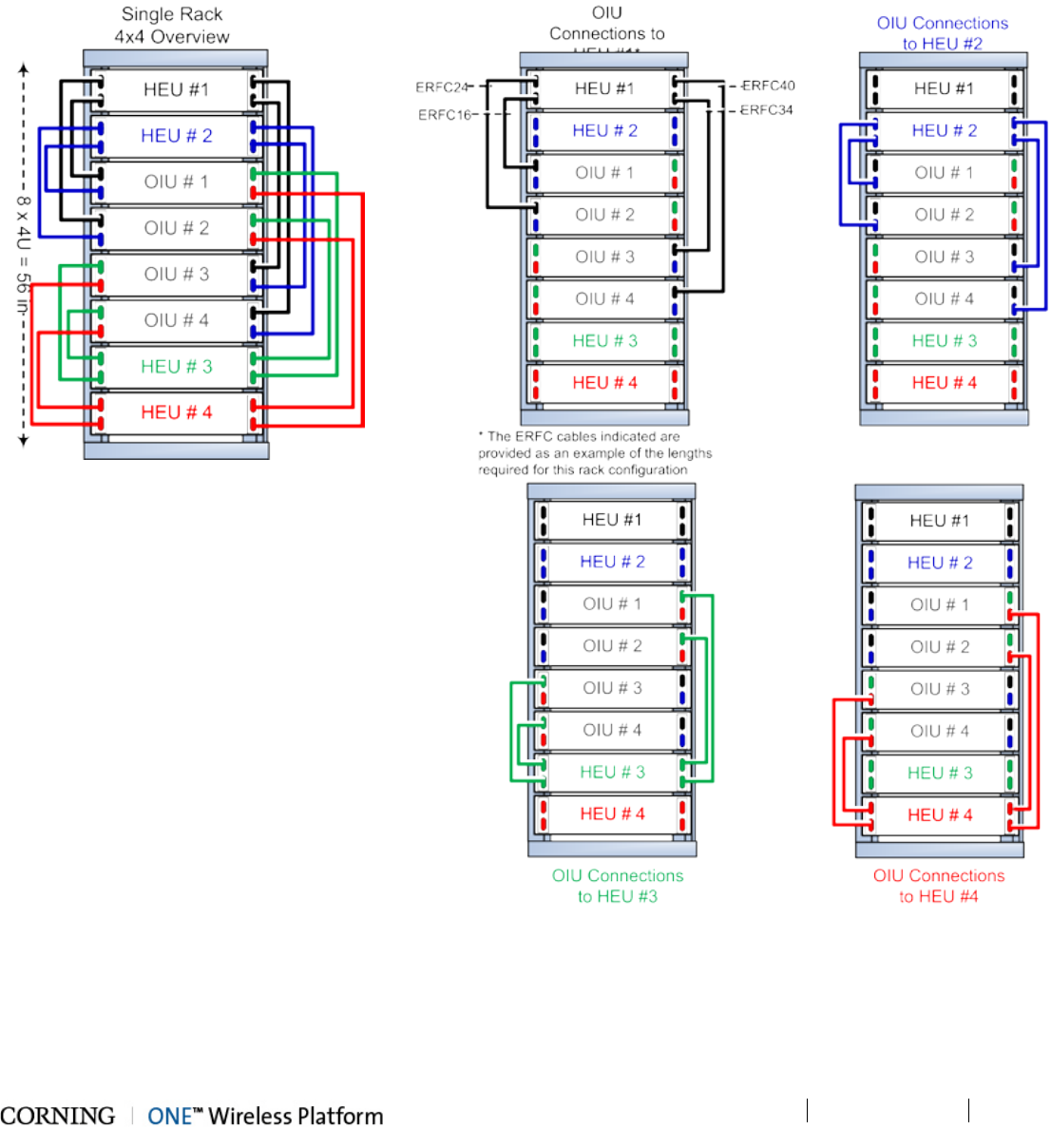
Installation – RF Path Elements P/N 709C011801 Page 69
DRAFT
5.1.2.7 Coax Connections for HEU-OIU 4X4 Installation Configurations
Figure 5-11 and Figure 5-12 illustrate the optimal installation configurations when installing four HEU and four OIU chassis in a
rack so that all HEU units can be connected to all OIU units. The optimal configuration takes into consideration the minimum
and maximum ERFC cable lengths (provided with OIX modules) in either a single 19-inch rack (shared rack equipment
scenario) or two separate racks (dedicated rack per operator).
Figure 5-11. HEU-OIU 4x4 Installation
Configuration for Shared
Provider
Equipment
Figure 5-12. HEU-OIU 4x4 Installation Configuration for Dedicated
Provider Equipment
Figure 5-11 illustrates how each HEU is connected to each OIU in a dedicated equipment (single rack) scenario. In Figure 5-12
the port numbers (1-4) indicated on each HEU correspond to the OIUs in the rack and vice versa for the OIU port numbers. For
example, Port 3 in HEU #1 indicates the connection to OIU #3, whereas Port 1 in OIU #3 indicates the connection to HEU #1.
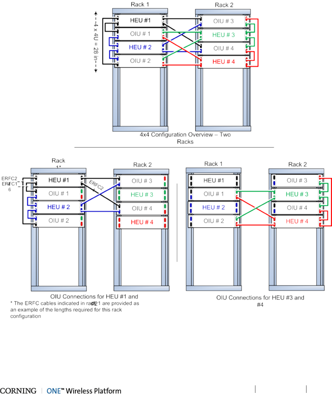
Installation – RF Path Elements P/N 709C011801 Page 70
DRAFT
Figure 5-13. 4x4 HEU-OIU Two Rack Configurations
Figure 5-13 illustrates how each HEU is connected to each OIU in a shared equipment (dual rack) scenario. In Figure 5-13. the
port numbers (1-4) indicated on each HEU correspond to the OIUs in the racks and vice versa for the OIU port numbers. For
example, Port 3 in HEU #1 indicates the connection to OIU #3, whereas Port 1 in OIU #3 indicates the connection to HEU #1.
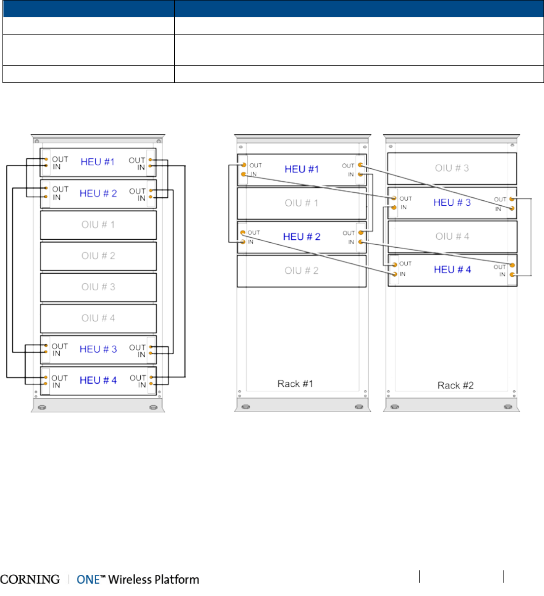
Installation – RF Path Elements P/N 709C011801 Page 71
DRAFT
5.1.2.8 RIX Pilot Clock Connections
Referring to Figure 5-14 (Shared Rack), use the QMA/QMA jumper cable to connect the REF OUT and REF IN ports of each of
the RIX modules in the HEU chassis.
Note that The REF IN and REF OUT pilot clock ports must be connected in a closed loop as shown in Figure 5-14 and
Figure 5-15 and that both RIX modules of each chassis must be connected.
From To
Main HEU RIX
REF OUT
1
st
Auxiliary HEU RIX
REF
IN
(For additional Auxiliary HEUs)
1st Auxiliary HEU RIX
REF
OUT
2nd Auxiliary HEU RIX
REF
IN
2
nd
Auxiliary HEU RIX
REF
OUT
3rd
Auxiliary HEU RIX
REF
IN
Table 5-3.IX Pilot Clock Connections
Figure 5-14 and Figure 5-15 show an example of the required pilot clock connections in 4x4 configurations.
Figure 5-14. Pilot Clock Connections Diagram
– (4x4) Shared Rack
Figure 5-15 Pilot Clock Connections Diagram – (4x4) Dedicated Rack
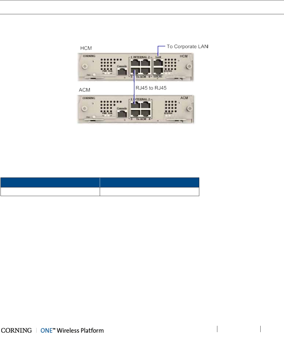
Installation – RF Path Elements P/N 709C011801 Page 72
DRAFT
5.1.2.9 Management Connections
Note 1: One RJ45/RJ45 management cable is provided with each HEU and OIU chassis.
Note 2: The management connections are also described in the HCM User Manual.
HCM to LAN connection
Using the provided RJ45/RJ45 communication cable, connect the HCM LAN port to the corporate LAN as shown in Figure 5-16.
Figure 5-16 HCM LOCAL Port to ACM Port LOCAL Management Connection
HCM to ACM Management Connections
Direct Management Connections (to up to four ACMs):
Referring to Figure 5-16, use RJ45/RJ45 communication cables to perform the Headend management connections according
to Table 5-4:
From (any) HCM… To (any) ACM…
INTERNAL (TO ACM) Port 1/2/3/4 INTERNAL (TO HCM) Port 1/2/3/4
Table 5-4. Direct Management Connections
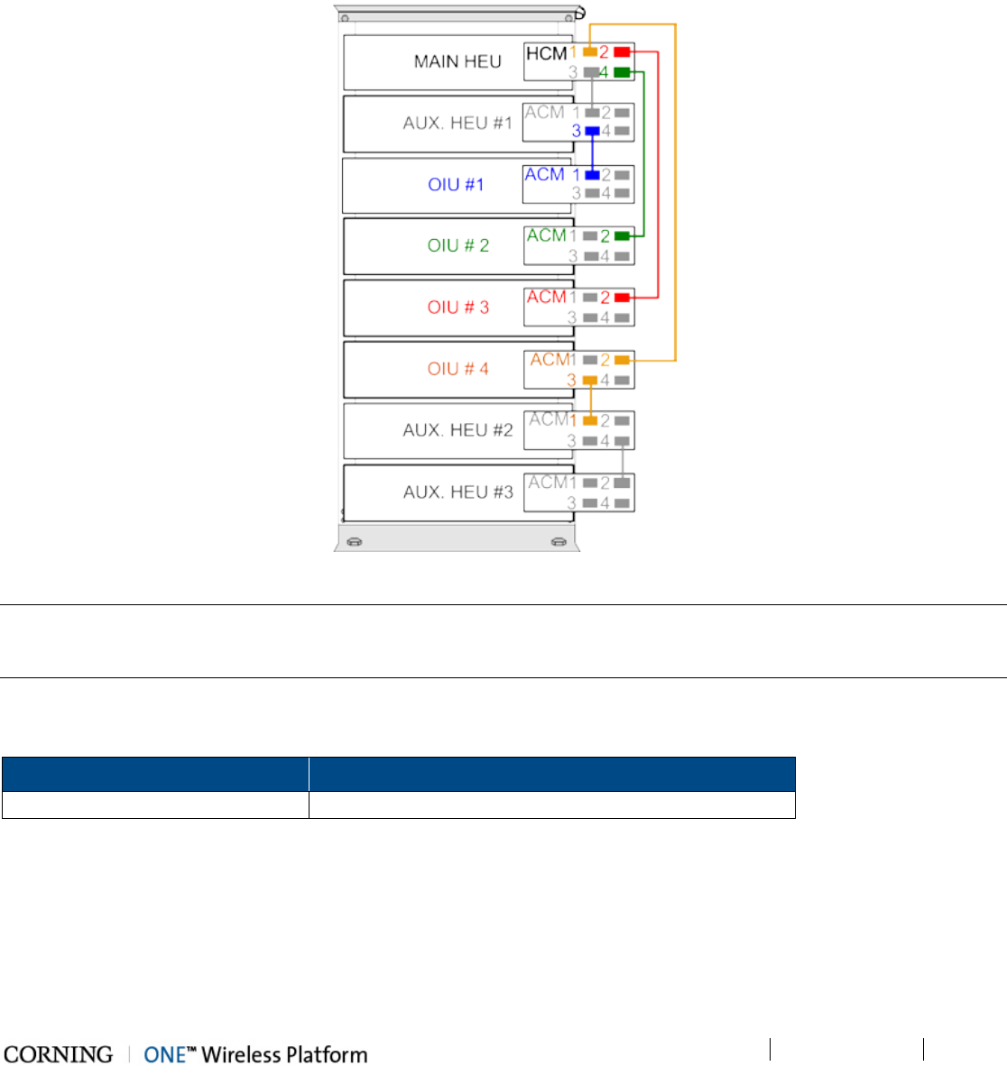
Installation – RF Path Elements P/N 709C011801 Page 73
DRAFT
Cascaded Management Connections:
The HCM supports cascaded management connections between ACM modules in cases where the system configuration
includes more than four ACM modules (e.g. 4x4 HEU-OIU configurations), where additional ACM modules and managed
devices are managed by the HCM via an indirect connection.
Figure 5-17 shows an example of how to cascade management connections in installations with more than four ACM modules.
Figure 5-17. Schematic Example of 4x4 Management Connections
Note: The management connections between the HCM and ACM modules are performed using CAT5 communication cables.
Make sure that an ACM which is directly connected to the HCM is done so via a single network connection, as to avoid
network conflicts (i.e. do not perform more than one connection between an ACM and HCM).
Where only HCM INTERNAL ports are available, use RJ45/RJ45 communication cables to perform the Headend management
connections as in Table 5-5:
From (any) HCM To (any) ACM
INTERNAL (TO ACM)
Port 1/2/3/4 Other available ACM module ‘INTERNAL (TO ACM)” port
Table 5-5. Indirect Management Connections
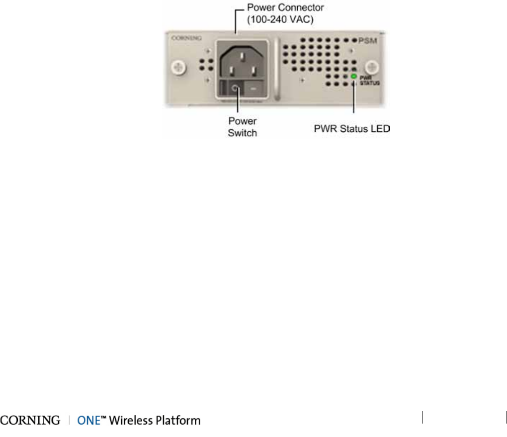
Installation – RF Path Elements P/N 709C011801 Page 74
DRAFT
5.1.2.10 Power Up
Note the following:
• The PSM modules are installed in the HEU and OIU chassis in one or both of the dedicated PSM slots (top left and middle)
• Two power supplies can be installed in the same chassis in order to provide redundancy.
• PSM-DC can be installed in the same chassis along with a PSM-AC module.
• If two modules are installed, both must be connected to their respective power source (AC or DC) and turned on at all times
after installation.
• For installations with two PSM modules, both modules must be:
• connected to the AC outlet
• switched ON to begin system operation
• turned on at all times
For PSM-AC modules
1. Connect power cable (100-240 VAC) supplied with module to the PSM-AC input connector and to the AC outlet and switch
on. See Figure 5-18
2. Verify that the Power Status LED on each PSM shows green. See Figure 5-18 for PSM-AC LED.
Figure 5-18. AC Power Supply Module LEDs
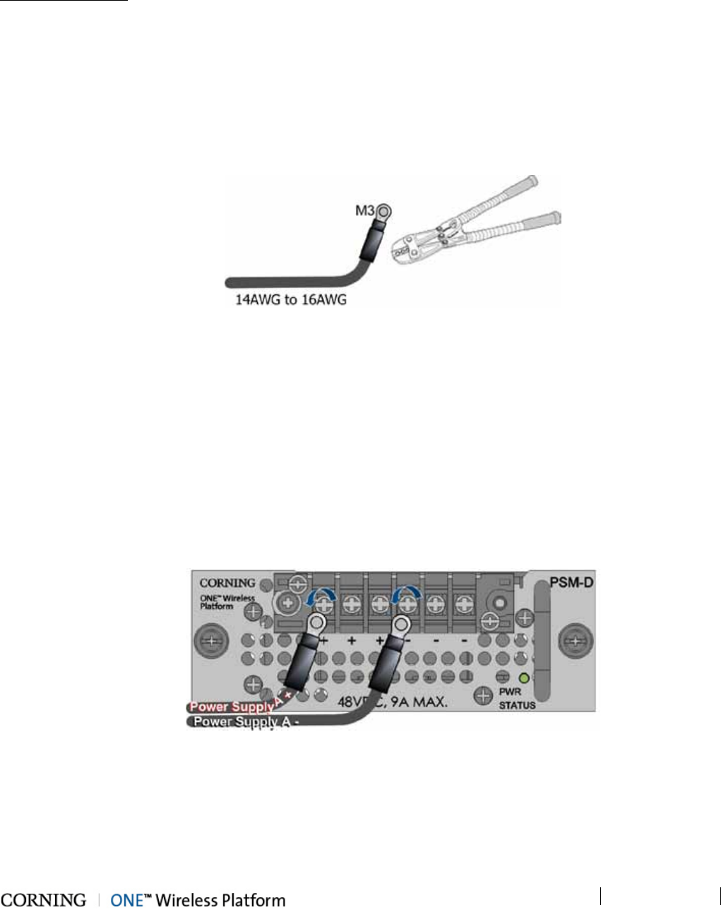
Installation – RF Path Elements P/N 709C011801 Page 75
DRAFT
For PSM-DC
General information:
• The PSM-DC is provided with six terminal rings (PN: 708A043001)
• Type of terminal ring provided: PMNF2-3R-C or PMV2-3RB-3K (depending on availability)
• PSM-DC power source rating: 48 V DC; 9A max.
To power up the PSM-DC module:
1. Crimp the provided terminal rings onto the DC wire pairs.
IMPORTANT! Make sure to use an appropriate crimper – do not use a plier!
Figure 5-19. Crimping the Terminal Rings onto the DC Wire
Required information:
• Type of terminal ring crimped onto DC wires – PANDUIT ring terminal:
• Compatible wire size: 1.5 – 2.5mm² wire range/14AWG to 16AWG
• M3 stud size
• No. of required wire pairs:
• Remote feed - three pairs; 100 W max. per pair
• Local Plant feed - two pairs; 100 W max. per pair
2. Connect crimped terminal rings to DC connectors.
IMPORTANT! Verify that the DC power source is OFF before connecting the wire pairs!
Figure 5-20. Connecting PSM-DC Wire Pairs
• Max. current consumption per pair:
• Remote feed = 1.55 A
• Plant feed = 4.65 A
• For optimal cable management, route all wire pairs to the left side of the rack
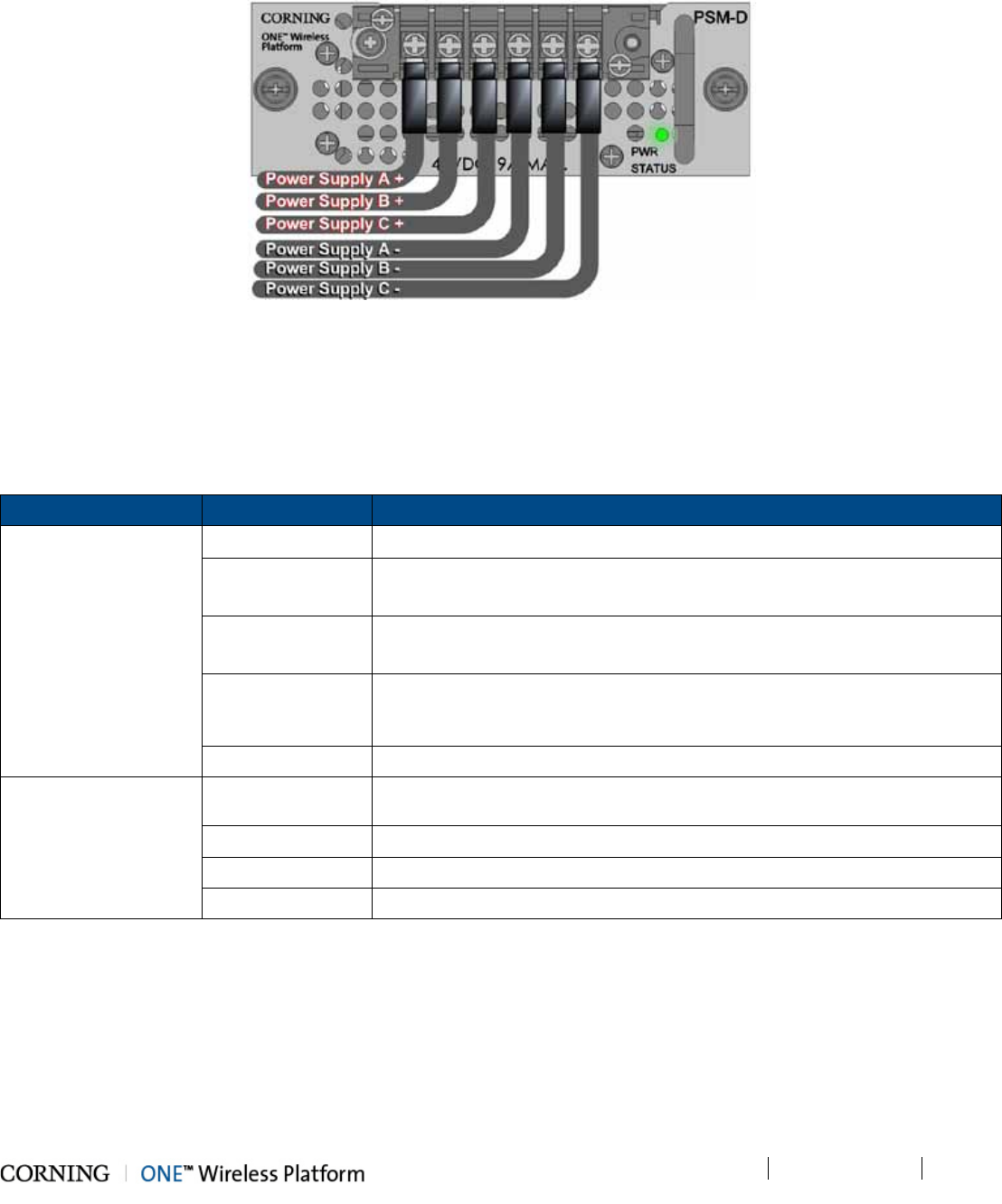
Installation – RF Path Elements P/N 709C011801 Page 76
DRAFT
3. Turn on DC source and verify that power status LED is green.
Figure 5-21. Connected DC Wire Pairs and Green Power LED
5.1.2.11 Verify Normal operation
1. Verify that the Power Status LED on each PSM shows green. See Figure 5-18 (PSM-AC) and Figure 5-21 (PSM-DC).
2. If RF source is operational, verify that the RIM (see Figure 5-22) and HCM/ACM (see Figure 5-23) LEDs indicate normal
operation according to Table 5-6:
Module LED Description
RIM Protect N/A
DL High Off - DL RF input level in threshold range
Steady Red – DL RF input level is 3dB above max expected power
DL Low Off - DL RF input level in threshold range
Steady Red - DL RF input level is 15dB below max expected power
RUN Blinking Green - RIM module SW has initialized and is up and running
Off – Power off
PWR Steady green - Input power is within required range
HCM/ACM PWR Steady Green - Power input detected by HCM/ACM
RUN Blinking Green – HCM module SW up and running
SYS Steady Green - Overall status of the managed system is ok
FAN Steady Green – Normal operation status for all fans
Table 5-6. RIM and HCM/ACM LED Descriptions
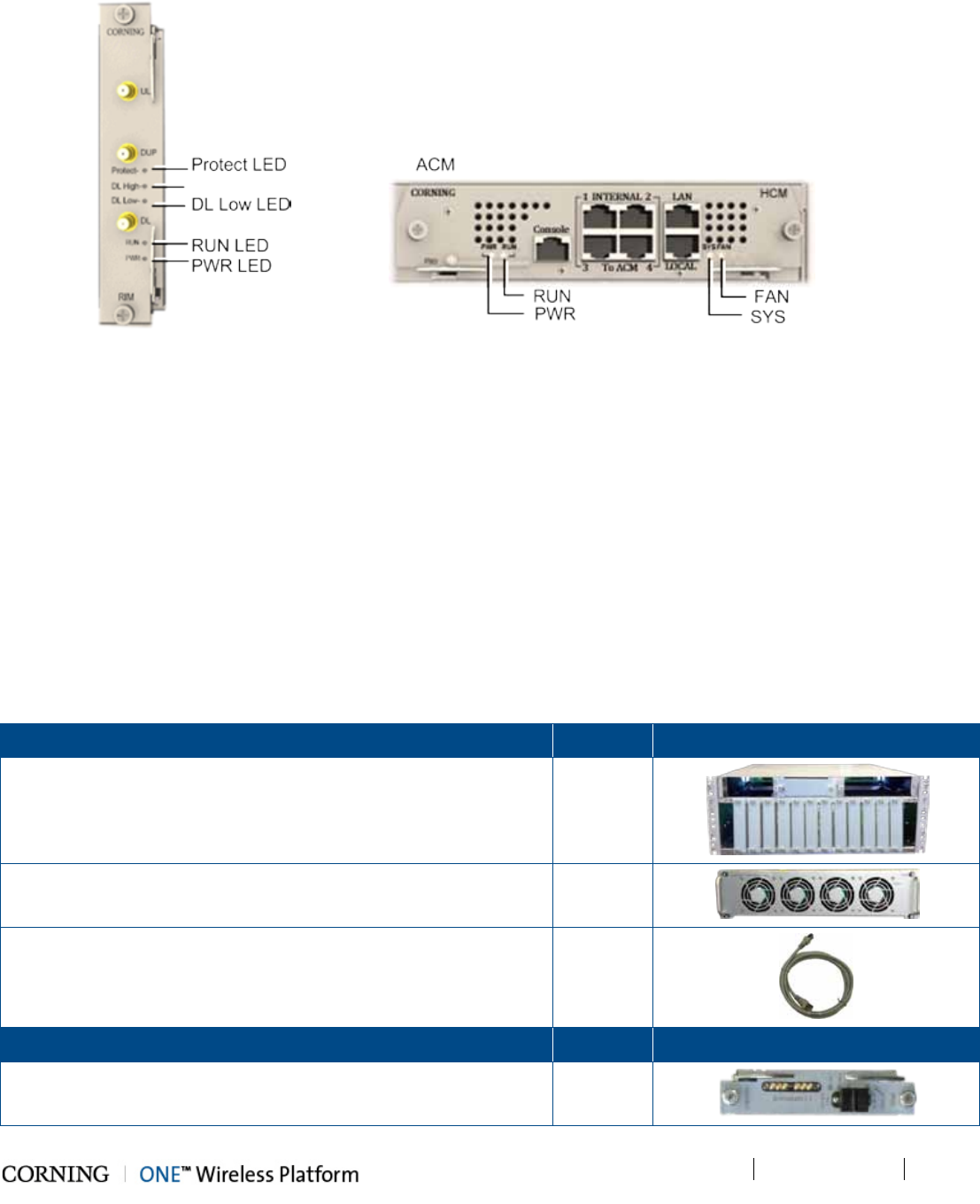
Installation – RF Path Elements P/N 709C011801 Page 77
DRAFT
Figure 5-22. RIM LEDs Figure 5-23. HCM/ACM LEDs
5.1.3 OIU Installation
Note the following:
• OIU chassis is supplied empty and only includes the factory assembled FAN Module (FAM). All other modules are ordered
separately and must be installed.
• The Cable management Tray can be assembled either before or after the unit is installed (see section 5.1.4 - HEU/OIU
Cable Management Tray).
5.1.3.1 Items Required for OIU Installation
The following items are required for installing the ONE™ OIU. If any of the listed items are missing, contact your Corning
representative.
OIU Kit
Quantity
Item
OIU Chassis (with blank panels) - with FAM Unit on the rear side of
the chassis
1
Fan Module (FAM) – one unit hosting four fans
(factory installed in chassis rear)
1
RJ45/RJ45 communication cable L=2m-2.15m (P/N 705900003) –
ACM management cable
1
OIM Kit (1-12 according to order)
Quantity
Item
Optical Interface Module (OIM)
1
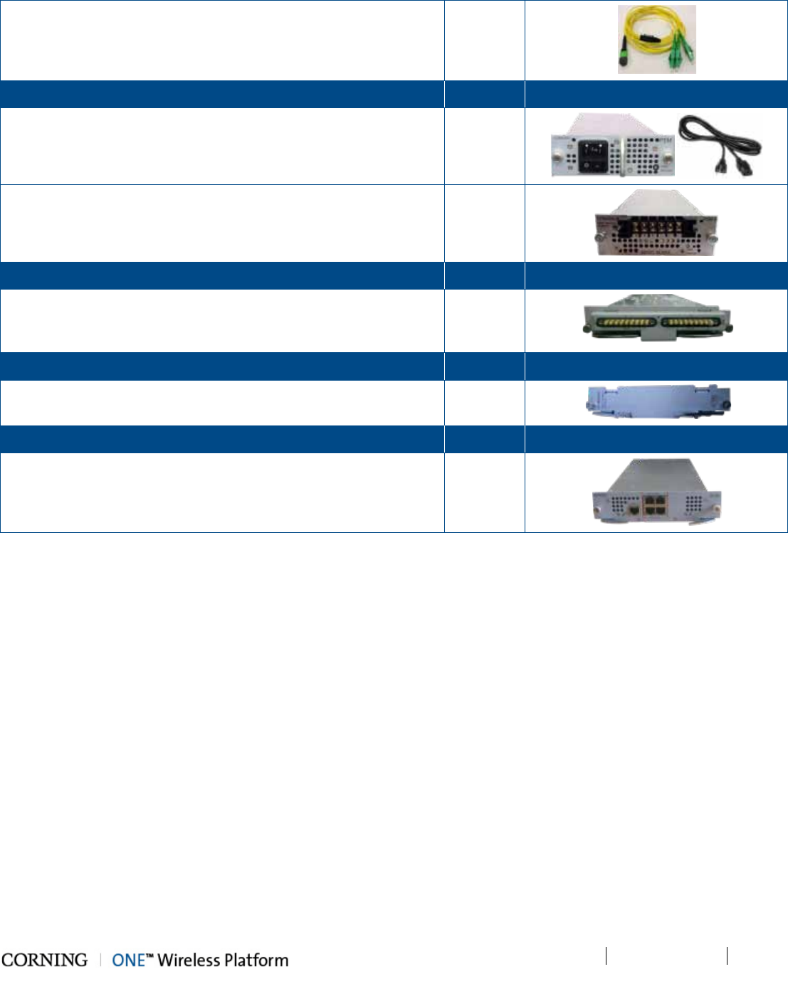
Installation – RF Path Elements P/N 709C011801 Page 78
DRAFT
MTP-LC APC Harness Cable (P/N 37HP900162-06F) - connector for
splitting fibers (6) leading from OIM to (FMU) Edge module
1
PSM Kit (AC or DC modules - 1 or 2 kits according to order)
Quantity
Item
PSM-AC: 100-240 VAC Power Supply Module including standard
IEC 60320-1 C13 cable
1
PSM-DC: 48 V DC Power Supply Module; 9 A Max.; Includes six pin
terminal block connector
1
OIU Expander Module Kit (1 or 2 according to order) Quantity Item
OIX (Optical Interface Expander Module) – connects to the HEU RIX
Expander module; provides RF interface to HEU
1
ETM Kit (according to order) Quantity Item
ETM (Expander Termination Module) - used for terminating unused
Expander slot
1
ACM Kit Quantity Item
ACM (Auxiliary Control Module) – enables remote (via HCM)/local
management of all hosted units
1
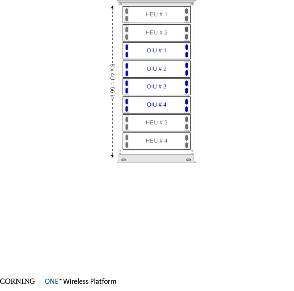
Installation – RF Path Elements P/N 709C011801 Page 79
DRAFT
5.1.3.2 Mounting Chassis in 19-in Rack
Note the following:
• Up to four OIU chassis can be connected to a single HEU
• OIU chassis requires 4U rack height availability
• Rack nuts and screws not provided (depend on rack type)
To mount OIU chassis
1. Determine the location of the OIU in the rack while considering additional HEU and OIU units and the lengths of the ERFC
cables (described in HEU Quick Start Guide).
2. Figure 5-24 and Figure 5-25 describe the optimal rack installations for 4x4 HEU-OIU configurations in dedicated or shared
equipment scenarios.
Figure 5-24. 4x4 Rack Installation Diagram – Dedicated.
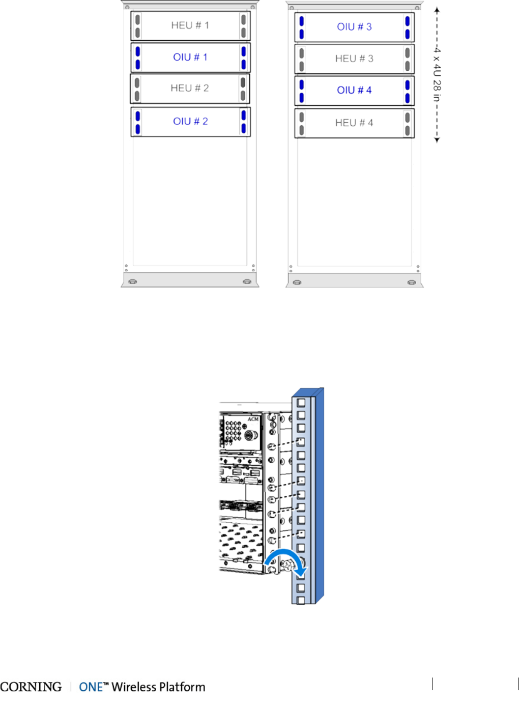
Installation – RF Path Elements P/N 709C011801 Page 80
DRAFT
Figure 5-25. 4x4 Rack Installation Diagram – Shared
3. Referring to Figure 5-26 secure the units’ rack ears to the rack frame as follows:
• Insert two screws half-way into the rack frame.
• Position the chassis on to the screws using the handles and the top and bottom half slots of the rack ears.
4. Secure the unit in the rack via all applicable bracket holes using the appropriate rack nuts and screws.
Figure 5-26. Installing Chassis in Rack
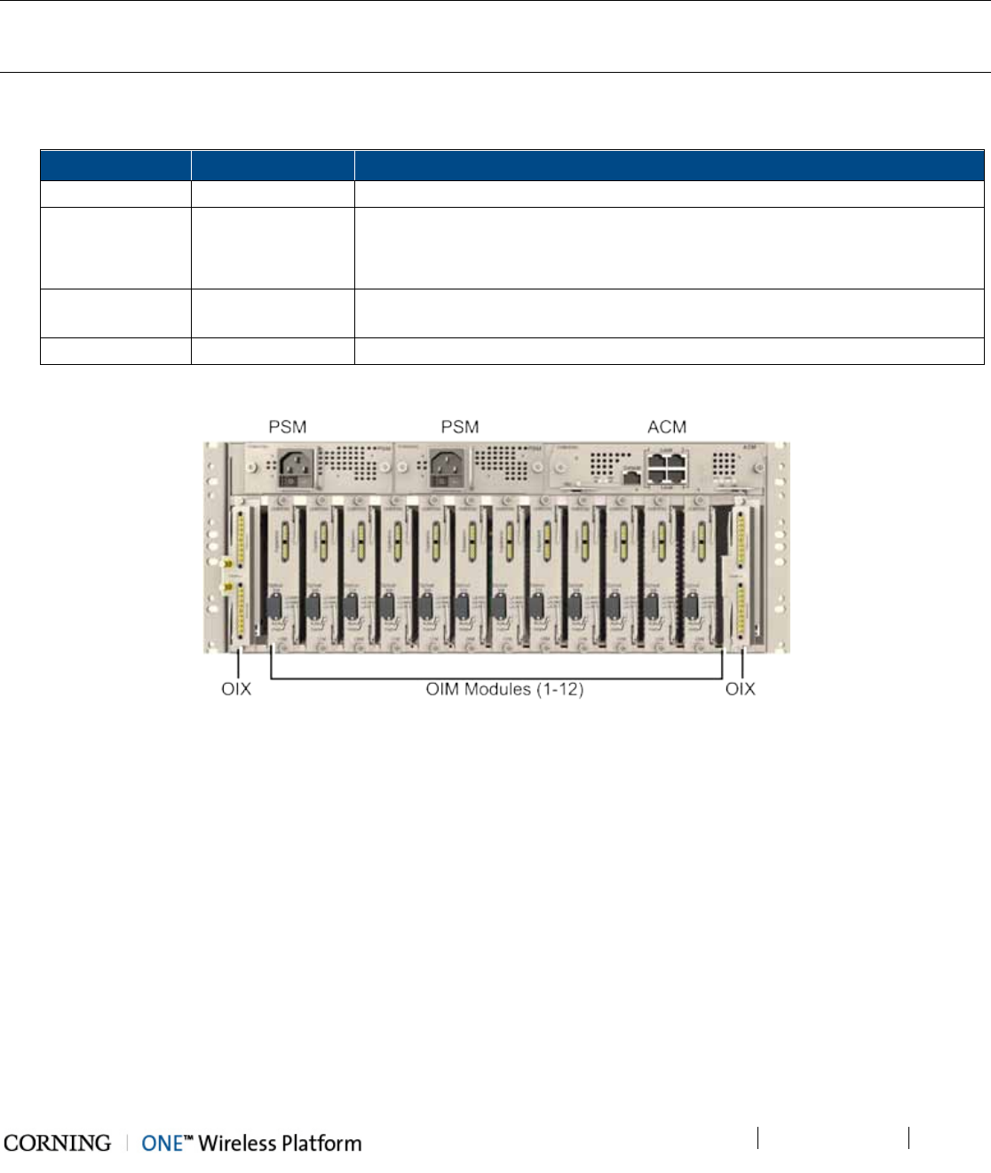
Installation – RF Path Elements P/N 709C011801 Page 81
DRAFT
5.1.3.3 Installing All Modules
Note: For modules with ejectors (i.e. OIM, OIX and ACM) – verify that the ejectors are completely open when inserting in
dedicated slot and then push in until the module clicks in to the backplane. Figure 5-28 shows example of module type
captive screws and ejectors.
1. Refer to Figure 5-27 for module locations. Remove blank panel (where relevant) and slide in the relevant module (chassis
slots are 100% mistake proof):
Module
Quantity
Comment
ACM 1 -
PSM 1 - 2 • For installations with one PSM module – install module in left most slot
• For installations with two PSM modules – remove blank panel from middle
slot and insert additional PSM module
OIX 1 - 2 For single OIX installations, the second OIX slot must be occupied with an
Expander Termination Module (ETM).
OIM 1 - 12 No need to terminate unoccupied OIM slot – leave blank panel
Figure 5-27. Location of OIU Front Panel Modules in Chassis
2. Secure modules into the OIU backplane by:
• Closing ejectors firmly (for relevant modules)
• Tightening the captive screws
See Figure 5-28.
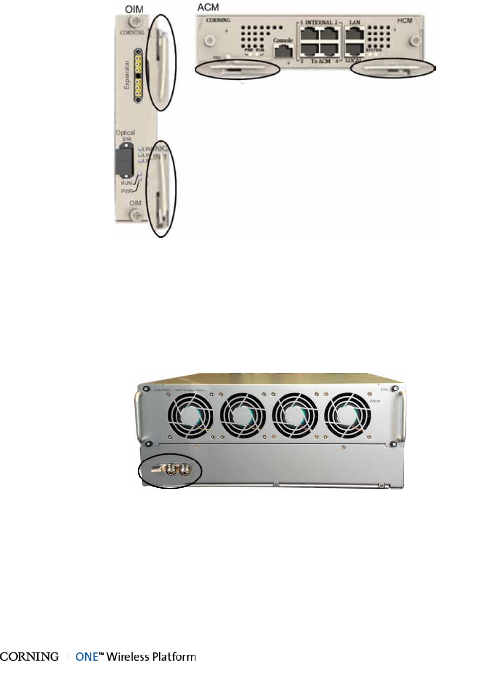
Installation – RF Path Elements P/N 709C011801 Page 82
DRAFT
Figure 5-28. Example of Module Type Captive Screws and Ejectors
5.1.3.4 Grounding Chassis
1. The grounding connection is performed via a two-hole, standard barrel grounding lug located on the HEU rear panel (see
Figure 5-29).
• For use with stranded copper wire conductors
• 10-14 AWG
• Holes - 1/4 inch.
Figure 5-29. OIU Grounding Lug (Chassis Rear)
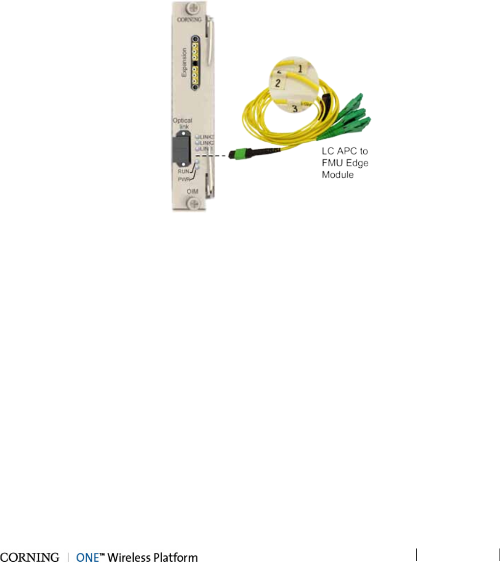
Installation – RF Path Elements P/N 709C011801 Page 83
DRAFT
5.1.3.5 Fiber Connections
1. Using the provided Corning MTP-LC APC Harness Cable:
• Connect the cable MTP® connector to the OIM MTP® connector
• Remove the protective plastic covers and connect the (3) LC APC connection fibers to the FMU Edge module LC APC
connections. See Figure 5-30.
2. Take note of the fiber numbering (1/2/3). See Figure 5-30.
Figure 5-30. OIM Fiber Connections
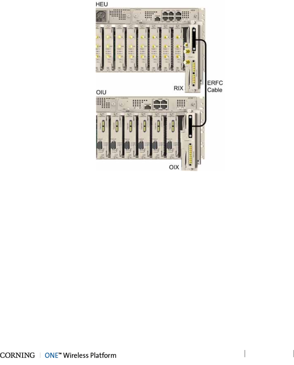
Installation – RF Path Elements P/N 709C011801 Page 84
DRAFT
5.1.3.6 RF Connections to HEU
RF connections between the OIU and HEU are performed using the ERFC cable (included in HEU order) and are described in
section 5.1.2.6 - RIX to OIX Connections. See Figure 5-31 for general view of connections.
Figure 5-31. OIX to RIX RF Connection
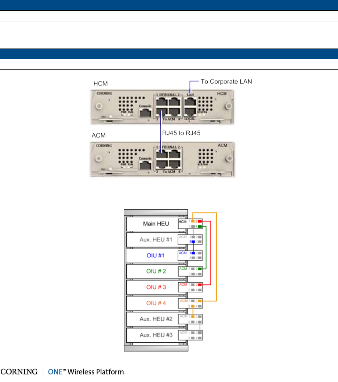
Installation – RF Path Elements P/N 709C011801 Page 85
DRAFT
5.1.3.7 Management connections
Using the provided RJ45/RJ45 communication cable, connect the OIU ACM control module as follows:
• Referring to Figure 5-32- for configurations with one HCM and up to four ACM modules (e.g. one HEU and four OIU units),
directly connect:
From any …. To any…
ACM ‘INTERNAL (TO HCM)’ port HCM ‘INTERNAL (TO ACM)” port
• For configurations with one HCM and more than four ACM modules (e.g. 4x4 HEU-OIU configurations) where there are only
four available HCM INTERNAL ports:
From any …. To any…
ACM ‘INTERNAL (TO ACM)’ port Other available ACM module INTERNAL (TO ACM)” port
Figure 5-32. Direct OIU to HEU Management Connection and ACM LEDS
Refer to Figure 5-33 for schematic example of management connections.
Figure 5-33. Schematic Example of 4x4 Management Connections
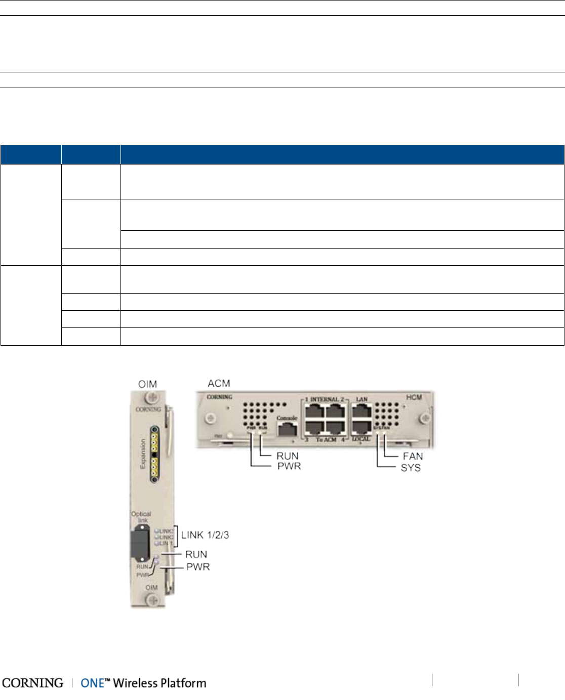
Installation – RF Path Elements P/N 709C011801 Page 86
DRAFT
Note: Main HEU refers to HEU with HCM, whereas HEU units with ACM modules are referred to as Auxiliary HEUs.
5.1.3.8 Power Up
Refer to HEU section 5.1.2.10 for details on connecting the AC/DC PSM modules.
Note: The PSM modules are common for both HEU and OIU chassis.
Verifying Normal Operation
If OIU chassis is powered on, verify that the OIM and ACM (see Figure 5-34) module LEDs indicate normal operation:
Module LED Description
OIM LINK 1/2/3 Steady Green - Optical link power to/from the connected remote is normal
Blinking Green - Optical power from remote is lower than required
RUN Blinking Green - OIM module SW has initialized and is up and running
Off – Power off
PWR Steady Green - Power input detected in OIM
ACM PWR Steady Green - Power input detected by ACM
RUN Blinking Green – ACM module SW up and running
SYS Steady Green - Overall status of the managed system is ok
FAN Steady Green – Normal operation status for all fans
Table 5-7. OIM and ACM LED Descriptions
Figure 5-34. OIM and ACM Module Status LEDs
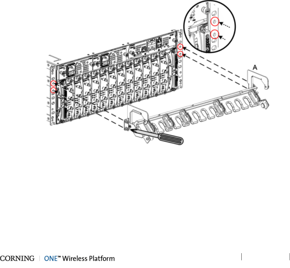
Installation – RF Path Elements P/N 709C011801 Page 87
DRAFT
5.1.4 HEU/OIU Cable Management Tray
The HEU/OIU Cable Management tray is an optional accessory that can be assembled onto the HEU and OIU chassis,
facilitating cable management and providing an aesthetic solution for organizing cable slack.
Note the following:
• The accessory can be assembled either before or after the HEU/OIU module cables are connected.
• The Cable Management Tray consists of two items:
• Cable Management Tray (P/N707A011301) – Item A in Step 1
• Door Sleeve (P/N 707A011201) – Item B in Step 4
• A Phillips screwdriver is required.
Assemble the Cable Management Tray as follows:
1. Assemble Cable Tray Onto Chassis
Figure 5-35. Assembling Cable Tray
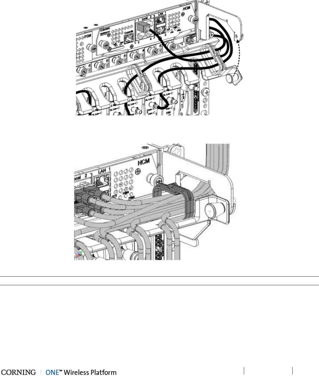
Installation – RF Path Elements P/N 709C011801 Page 88
DRAFT
2. Route Connection Cables Through Cable Tray (From the Middle Leftwards/Rightwards) and Pull Up Tray
Figure 5-36. Assembling Cable Tray
3. Close Management Tray (as shown in figure)
Figure 5-37. Assembling Cable Tray
Note: The tray pin must first be pulled towards the left and then released into the hole (shown in figure above).
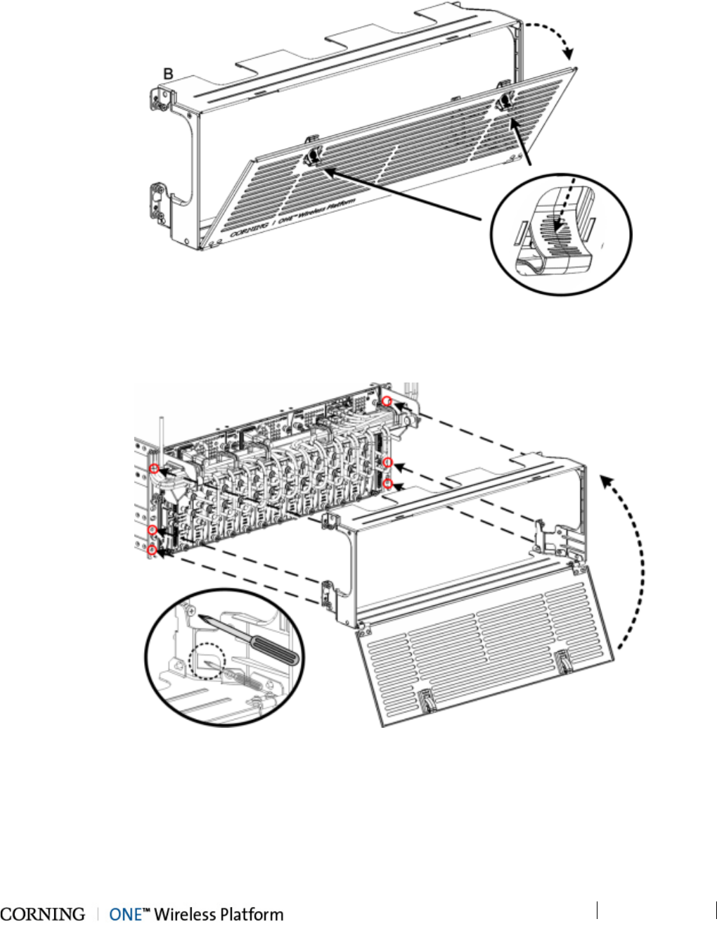
Installation – RF Path Elements P/N 709C011801 Page 89
DRAFT
4. Pull Down the Cover Door
Figure 5-38. Assembling Cable Tray
5. Assemble Cover onto Chassis
Figure 5-39. Assembling Cable Tray
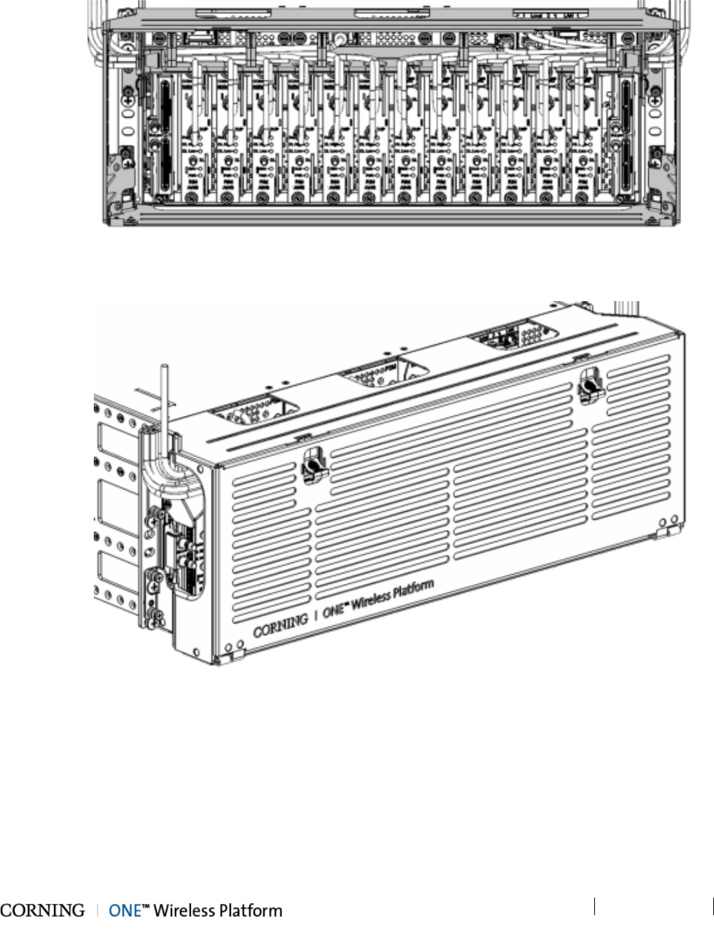
Installation – RF Path Elements P/N 709C011801 Page 90
DRAFT
6. View of Assembled Chassis and Cover – Open
Figure 5-40. Assembling Cable Tray
7. View of Assembled Chassis and Cover – Closed
Figure 5-41. Assembling Cable Tray
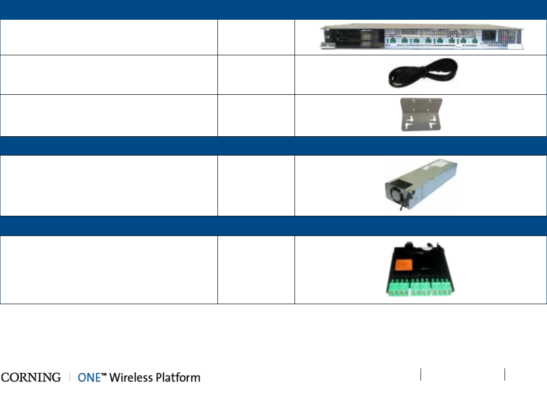
Installation – RF Path Elements P/N 709C011801 Page 91
DRAFT
5.2 RF Remote-End Installation
The remote end site (RF coverage) installation consists of installing the ICU and RAU module(s).
5.2.1 ICU Installation
Note the following:
• The ICU is a passive unit installed at the floor level and provides the power and fiber interfaces to the RAU units (and to the
GEU for the digital path).
• Connections between the ICU and the RAU units are performed via Corning composite cables (ordered separately)
consisting of:
• two DC wires
• three LC APC pairs
• The chassis and modules are supplied separately and must be inserted by the user.
• All ICU modules (i.e. PS and Edge) are hot-swappable
• Each ICU chassis hosts up to four Power Supply modules and up to two Edge modules
5.2.1.1 Items Required for ICU Installation
The following kits and included items are required for installing the ICU. If any of the listed items are missing, contact your CMA
representative.
ICU Chassis Kit Quantity Item
ICU Chassis 1
IEC 60320-1 C13 right angled, AC power cable
110-240V AC, 50-60
1
Wall mount bracket 2
Power Supply Kit (1 to 4 according to order) Quantity Item
Power supply module 1
Edge Module Kit (1to 2 according to order) Quantity Item
Edge Module 1
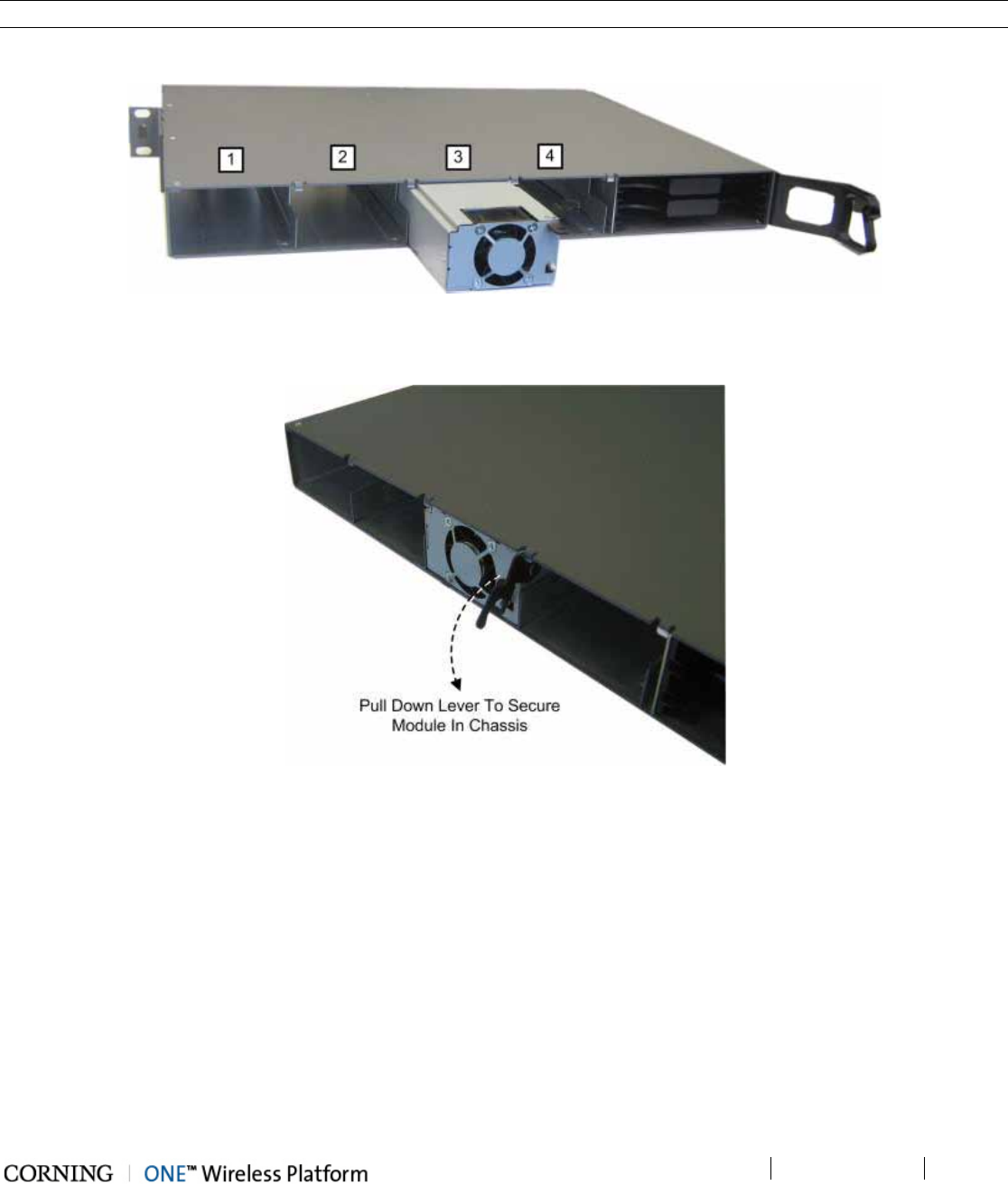
Installation – RF Path Elements P/N 709C011801 Page 92
DRAFT
5.2.1.2 Installing Power Supply Module
Note: The power supply modules are hot-swappable and can be installed/extracted either before or after power-up.
1. With the lever up, slide the power supply module into any of 1-4 PS slots on the ICU chassis rear (Figure Figure 5-42).
Figure 5-42. Inserting Power Supply Module
2. Push in the module until the lever meets the chassis (Figure 5-43).
Figure 5-43. Securing PS Module in ICU Chassis
3. Secure by pulling the lever downward until it “clicks" and module is flush with chassis rear.
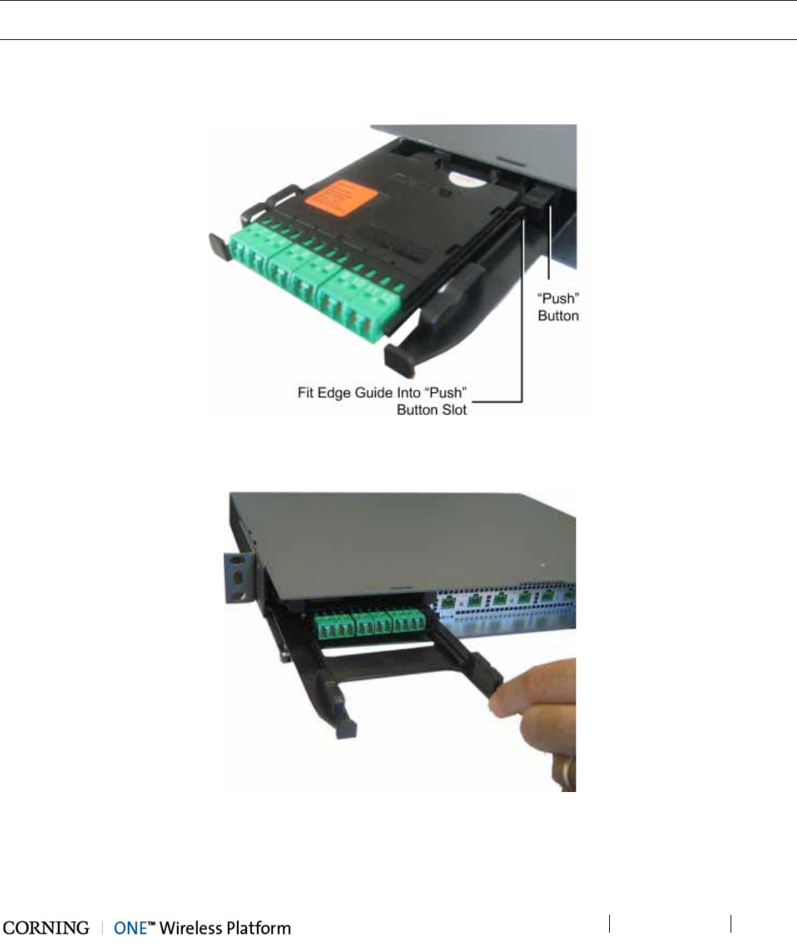
Installation – RF Path Elements P/N 709C011801 Page 93
DRAFT
5.2.1.3 Installing Edge Module
Note: The Edge module can be installed from either the front or the rear of the ICU chassis. This procedure illustrates a front
side installation.
1. Pull one of the Edge module trays all the way out – until it “clicks”.
2. Slide in the Edge module between the guides and fit the module guide into the tray “Push” button slot, as shown in
Figure 5-44.
Figure 5-44. Inserting Edge Module (Chassis Front)
3. Push the module gently in until it “clicks” and is “flush” with the ICU panel - leaving the tray in place. See Figure 5-45.
Figure 5-45. Edge Module Flush with Panel (Chassis Front)
4. Push the tray back in place.
5. Repeat Steps 1-4 for additional Edge module.
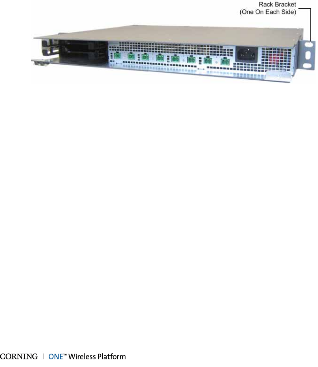
Installation – RF Path Elements P/N 709C011801 Page 94
DRAFT
5.2.1.4 Mounting ICU in 19-IN Rack
Note the following:
• Continue to next section if ICU is to be mounted on wall.
• If the ICU is rack mounted, the modules can be inserted either before or after the unit is mounted.
1. Mount the ICU in the 19-in communication rack and secure using pre-assembled bracket.
Figure 5-46. ICU Rack Brackets
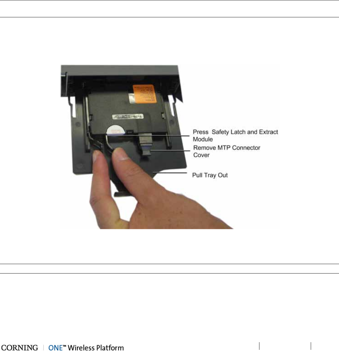
Installation – RF Path Elements P/N 709C011801 Page 95
DRAFT
5.2.1.5 Mounting ICU on Wall
1. Remove the rack mounting brackets and set the screws aside.
2. Using the screws (previously set aside), assemble the wall mount brackets onto the sides of the ICU.
3. Using the wall mount bracket holes as a guide, mark the holes to be drilled on the wall.
5.2.1.6 Connect MTP Fiber
Note: The fiber connection is performed between the Edge module MTP connector and the FMU (Fiber Management Unit)
using a trunk cable.
4. From the rear panel, pull the tray with the Edge module all the way out.
5. Gently extract the edge module by pressing on the safety latch and pulling slowly outwards. Refer to Figure 5-47.
6. Remove the MTP connector cover and connect the MTP fiber cable.
7. Push in the module tray.
Figure 5-47. Extracting Edge Module
5.2.1.7 Composite Cable Connections
Note: The composite cable connections are connected towards the RAU and/or GEU units.
1. Connect one side of the composite cable DC wiring to any of the ICU DC power connectors (1-8) on the front panel. See
Figure 5-48.
2. Extract the Edge module (see Steps 1-4 of 5.2.1.6), remove the tip covers from the composite cable fiber pairs and
connect to the Edge module LC/APC fiber connectors. See Figure 5-48.
3. Note the cable coding on the fibers.
4. Push Edge module and tray back in place.
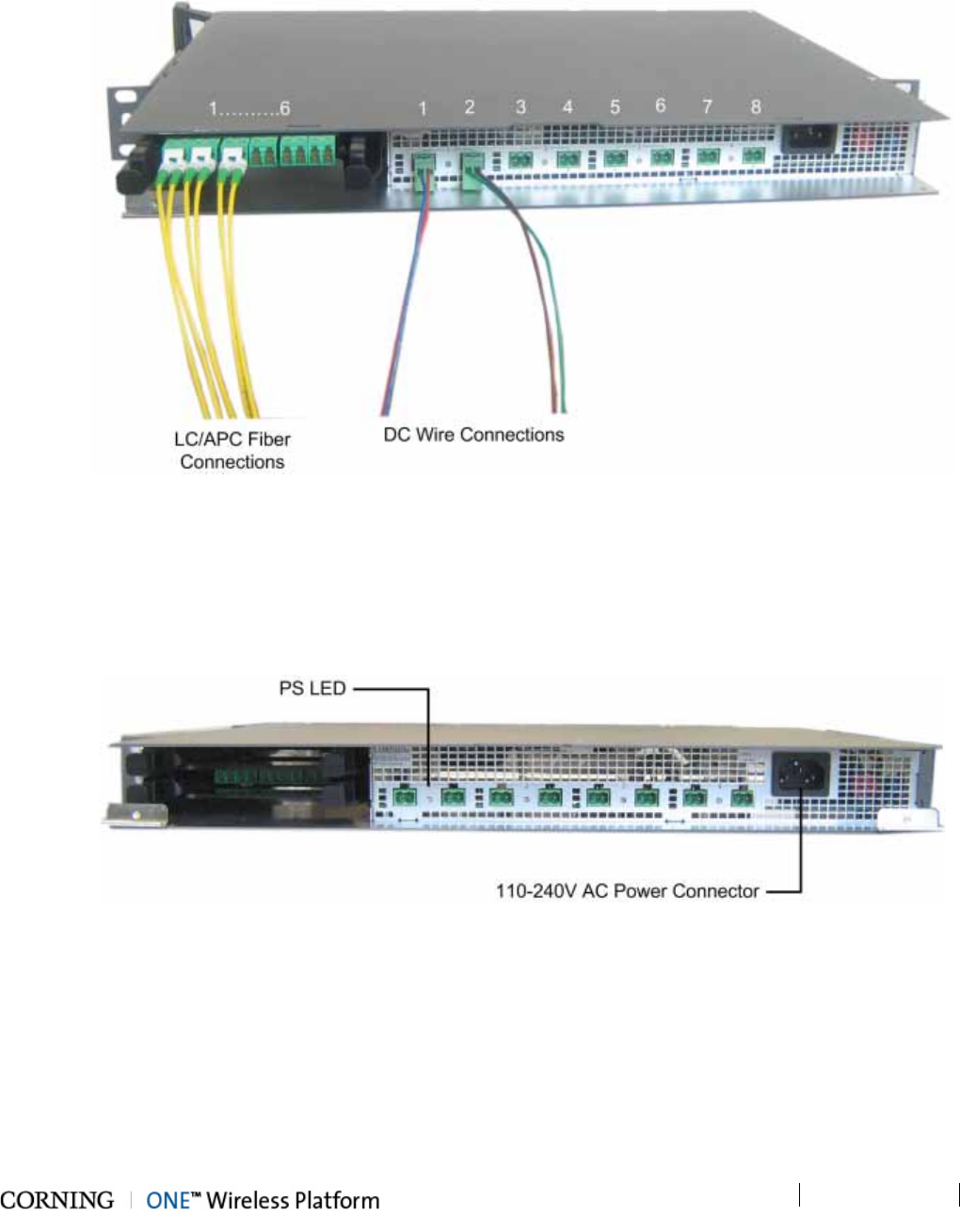
Installation – RF Path Elements P/N 709C011801 Page 96
DRAFT
5. Connect the DC wiring and fibers from the opposite end of the composite cable to the RAU/GEU units - described in
corresponding QSG documents.
Figure 5-48. ICU Fiber and DC Connectors
5.2.1.8 Power Up
1. Connect the ICU power connector (front panel) to the AC power outlet using the provided power cable.
2. Verify that the PS LED indicators (located between the corresponding DC connectors on the front panel) show green. Refer
to Figure 5-49.
Figure 5-49. AC Power Connection and LEDs
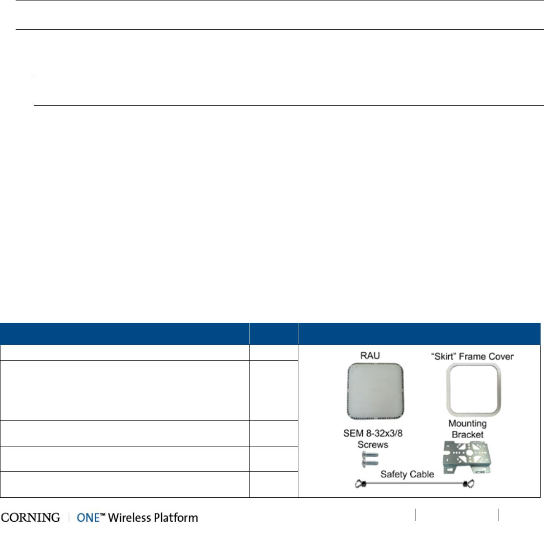
Installation – RF Path Elements P/N 709C011801 Page 97
DRAFT
5.2.2 RAU Installation
5.2.2.1 General Information
• The RAU modules are deployed on the floor level and interface to the RF antennas.
• The RAU can be provided in a number of configurations:
• RAU (without RxU and GEM)
• RAU + RxU
• RAU + GEM
• RAU + RxU + GEM
Note: Existing RAU units can be upgraded with RxU (for MIMO support) and/or GEM modules (for Ethernet services) – see
Appendix A for instructions on how to upgrade the RAU with these modules.
• The RAU supports various mounting installation options:
• Wall
• Ceiling/acoustic ceiling
Note: If the RAU is installed below or mid-mount an acoustic ceiling, a support bar (T-Bar) is required (not included).
Acoustical ceiling grid work is not designed to support the weight of the enclosure.
• Required ambient temperature:
• Wall-mount installations (vertical): 45◦C [113◦F]
• Ceiling-mount installations (horizontal): 50◦C [122◦F]
• RAU weight:
• RAU Alone: 7.93 (3.6 kg)
• RAU + RxU + GEM: 12.12 lbs (5.5 kg)
• RAU optic fiber connections and DC power are provided via a Corning Composite cable (ordered separately).
• External cavity filters are required for installations in which RAU/RXU modules supporting the corresponding CELL and LTE
bands are deployed alongside units supporting the public safety service. See section 5.2.3.
5.2.2.2 Package Contents
Check your package contents to verify that the items in the packing list are included. If any of the listed items are missing,
contact your Corning representative.
Item Quantity Image
Remote Antenna Unit (RAU)
1
Mounting Bracket (factory assembled on RAU
underside)
Note: Mounting Bracket includes holes in various sizes
and locations for flexible installation options. Mounting
screws not provided.
1
Screw, SEM 8-32X3/8 , Pan Head, Philips - used for
grounding and to secure bracket to RAU
2
“Skirt” Frame Cover – used for acoustic ceiling cut-out
template and for aesthetic installation
1
Safety Cable – used to secure RAU to permanent
structure in acoustic ceiling installations
1
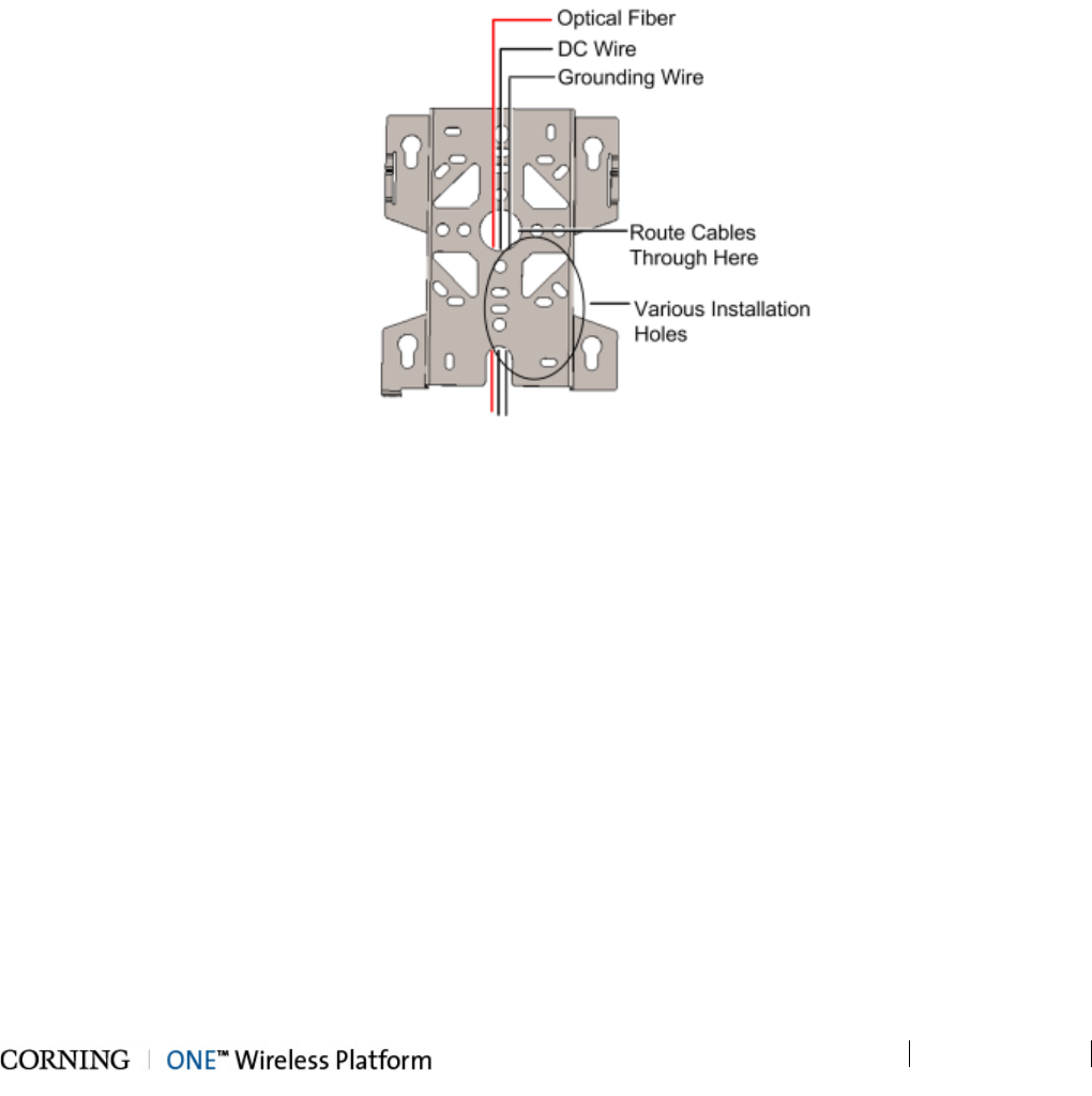
Installation – RF Path Elements P/N 709C011801 Page 98
DRAFT
5.2.2.3 Routing Connection Cables
1. Locate the following connection cables:
• DC wiring:
o One pair for MAIN POWER connection
o One pair for SECONDARY POWER connection (for RAU models including GEM module)
• Fiber pairs:
o One fiber pair for RAU module
o One fiber pair for GEM module (for RAU models including GEM)
• Grounding wire
2. Route the connection cables through center of the Mounting Bracket. See Figure 5-50.
Figure 5-50. Routing Connection Cables through Bracket
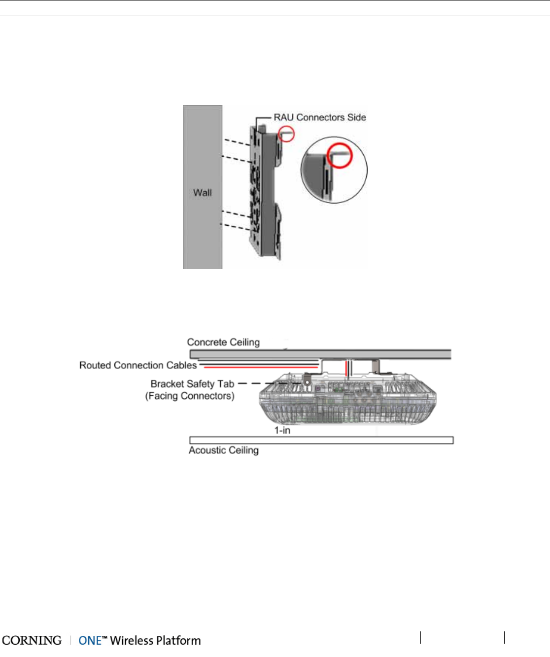
Installation – RF Path Elements P/N 709C011801 Page 99
DRAFT
5.2.2.4 Mounting RAU Installation Bracket (Wall/Concrete Ceiling)
Note: If using the RAU mid-mount bracket accessory kit – refer to section 5.2.2.6.
Note the following:
• When mounting the bracket, the Safety tab (circled in Figure 5-51 and Figure 5-52) should always be positioned to face the
same direction as the RAU connectors (up or down).
• When installing above acoustic ceiling, allow for at least 1 inch above the acoustic ceiling for air flow cooling. See
Figure 5-52.
Figure 5-51. Wall Mount Bracket Installation
Remove mounting bracket from RAU underside and mount the bracket on the wall (Figure 5-51) or concrete ceiling
(Figure 5-52) using any of the applicable screw holes (screws not provided).
Figure 5-52. Above Acoustic Ceiling Installation
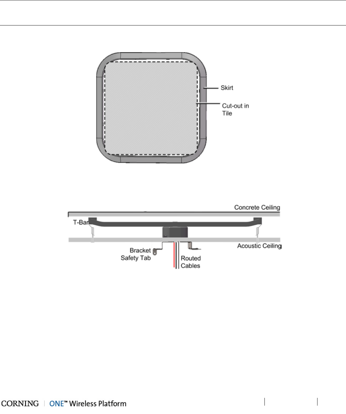
Installation – RF Path Elements P/N 709C011801 Page 100
DRAFT
5.2.2.5 Additional Bracket Installation Options
Note 1: A T-Bar Mounting Bracket can be used (not provided) to mount the RAU below or mid-mount an acoustic ceiling.
Note 2: A mid-mount installation option including a panel for replacing acoustic tile is available using the separately ordered
RAU mid-mount accessory kit (P/N: AK-RAU-BRCK-MM) – refer to section 5.2.2.6.
1. For mid-mount only - using the inner circumference of the RAU Skirt (provided) as a template, cut out an opening in the
acoustic ceiling tile for the RAU. See Figure 5-53.
Figure 5-53. Skirt for Mid-Mount Cut-Out
2. Install the T-Bar on the ceiling above the acoustic tiles (according to manufacturers’ instructions) and route the previously
located connections cables through the center of the RAU Mounting Bracket. See Figure 5-55.
Figure 5-54. Routed Cables and Mounting Bracket Installed on T-Bar (Below Ceiling)
3. Install RAU bracket on the T-Bar, using any of the applicable bracket installation holes.
Note the following:
• Safety tab should face the direction of the RAU connectors
• Below Ceiling – 1-in minimum between ceiling tile and RAU (shown in Figure 5-56)
• Mid-Mount – 2.5 in (63.5 mm) between ceiling and lowest part of RAU (shown in Figure 5-56)
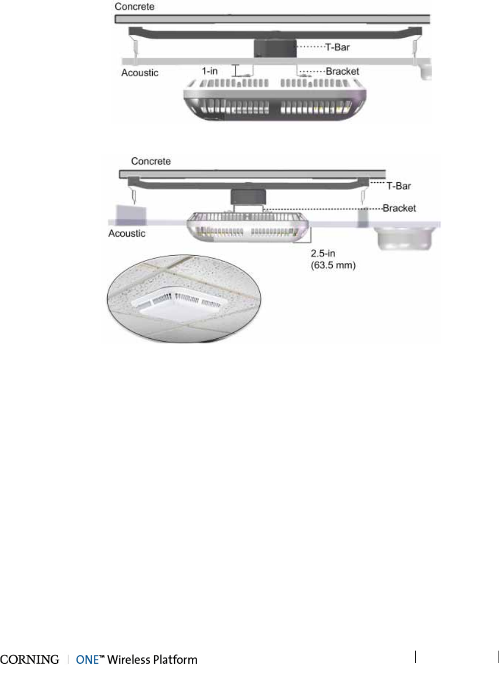
Installation – RF Path Elements P/N 709C011801 Page 101
DRAFT
Figure 5-55. Below Acoustic Ceiling Installation
Figure 5-56. Mid-Mount Acoustic Ceiling Installation
4. Route the connections cables (previously located) through the center of the RAU Mounting Bracket.
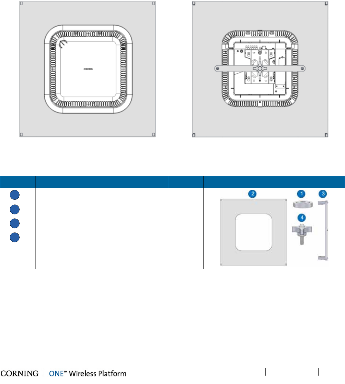
Installation – RF Path Elements P/N 709C011801 Page 102
DRAFT
5.2.2.6 RAU Mid-Mount Installation Option
The RAU mid-mount bracket accessory kit (AK-RAU-BRCK-MM; ordered separately) provide an aesthetic solution for a
installing the RAU in mid-mount of an acoustic ceiling. The kit includes a tile like panel onto which the RAU is mounted and
which replaces a standard acoustic ceiling tile.
Figure 5-57. RAU Mid-Mount Complete Assembly – Top (Right) and Bottom (Left) View
RAU Mid-Mount Bracket Accessory kit Items
Item No. Description Quantity
1
Plate
1
2
Spacer
1
3
Assembled flat bar
1
4
Nylon four arm knob with threaded stud
1
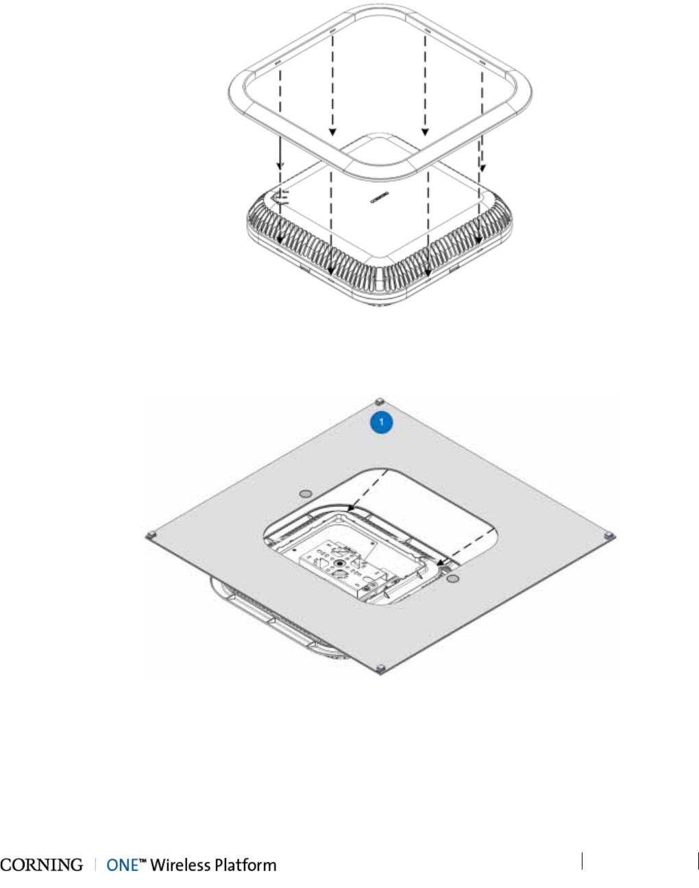
Installation – RF Path Elements P/N 709C011801 Page 103
DRAFT
To install the mid-mount option:
5. Referring to Figure 5-58, assemble the RAU Frame Cover (provided with the RAU) onto the RAU.
Figure 5-58. Assembling RAU Frame Cover
6. Position the RAU on a flat surface with the mounting bracket facing upwards and lower the plate (Item 1) onto the RAU, as
shown in Figure 5-59.
Figure 5-59. Lowering Plate onto RAU
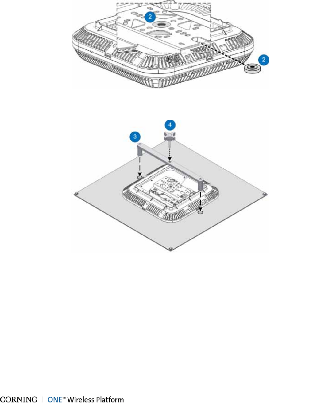
Installation – RF Path Elements P/N 709C011801 Page 104
DRAFT
7. Slide the Spacer (Item 2) in through the RAU mounting bracket and insert into bracket middle hole. Refer to Figure 5-60.
Figure 5-60. Inserting Spacer into RAU Mounting Bracket
8. Assemble Flat Bar (Item 3) and Knob (Item 4) as shown in Figure 5-61.
Figure 5-61. Assembling Flat Bar and Knob onto Plate
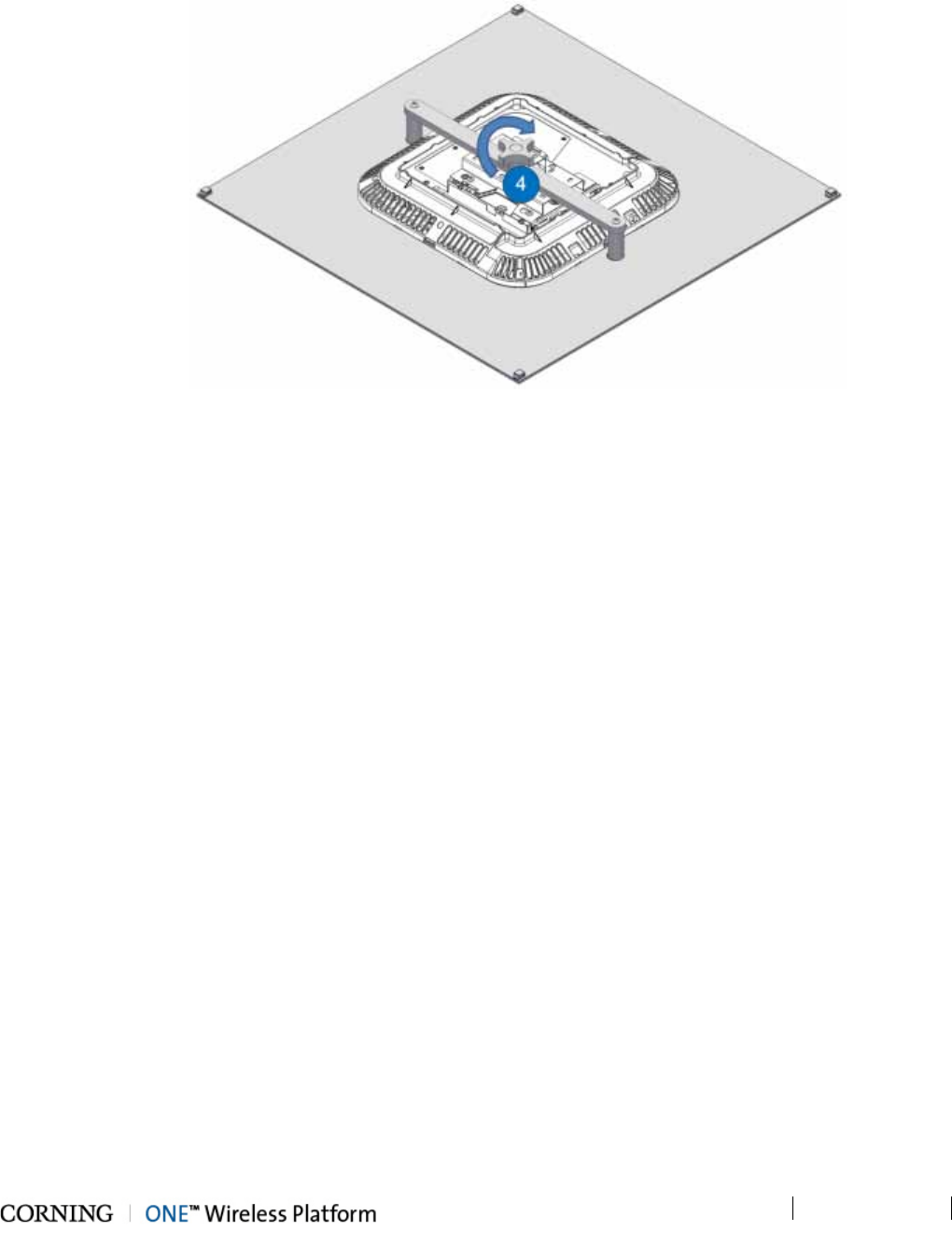
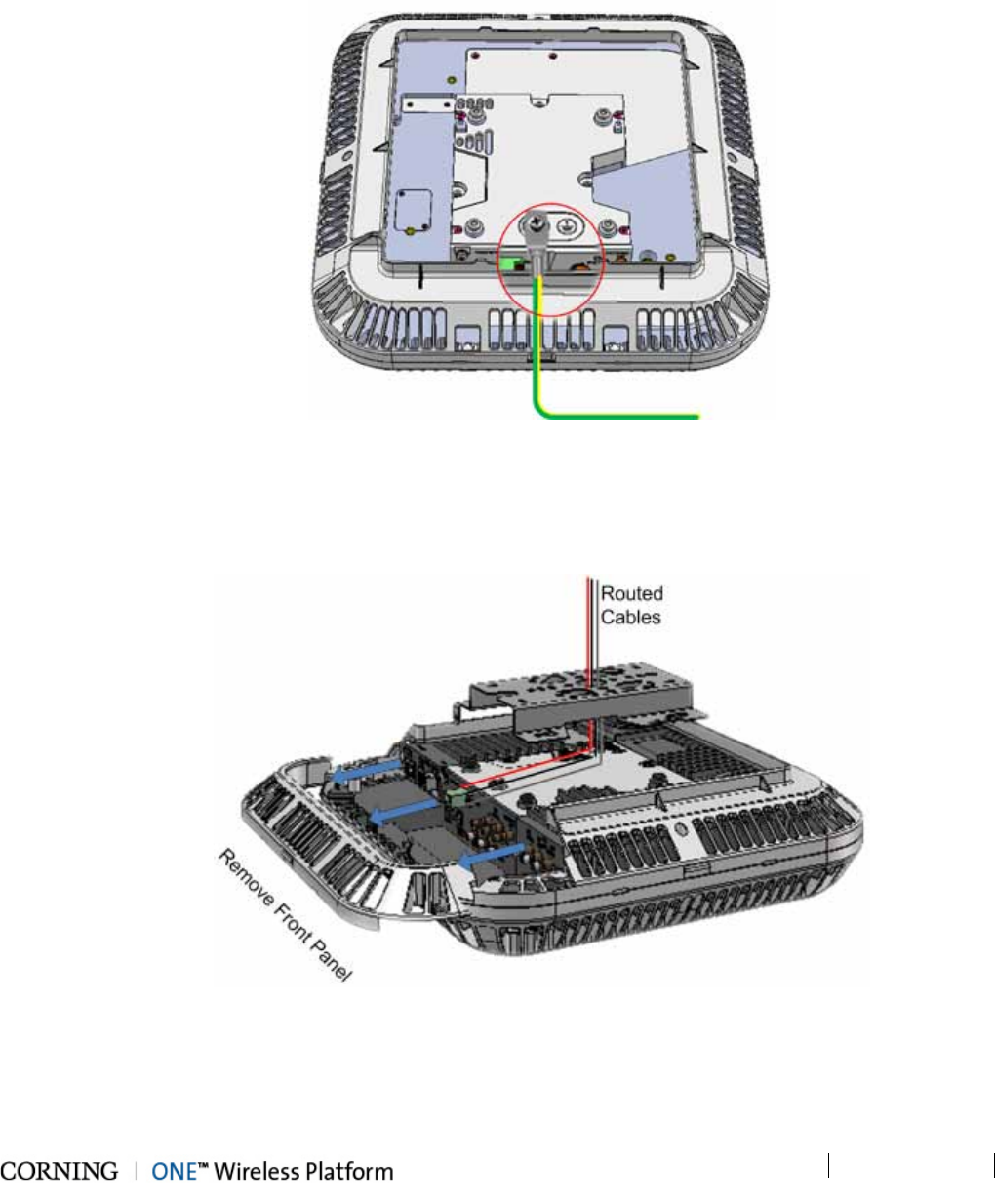
Installation – RF Path Elements P/N 709C011801 Page 106
DRAFT
5.2.2.7 Cable Connections
1. Hold the RAU near the mounting bracket and routed cables.
2. Connect the earth ground to the RAU using one of the provided 8-32X3/8 screws. See grounding bolt location circled in
Figure 5-63.
Figure 5-63. Grounding Bolt Location
3. Pull the front panel and remove to access connectors. See Figure 5-64.
4. Route the cables over the top of the RAU and towards the front panel connectors, where the bracket will be located. (The
cables will be routed between the RAU and the bracket). See Figure 5-64.
Figure 5-64. Route Cables towards RAU Connectors
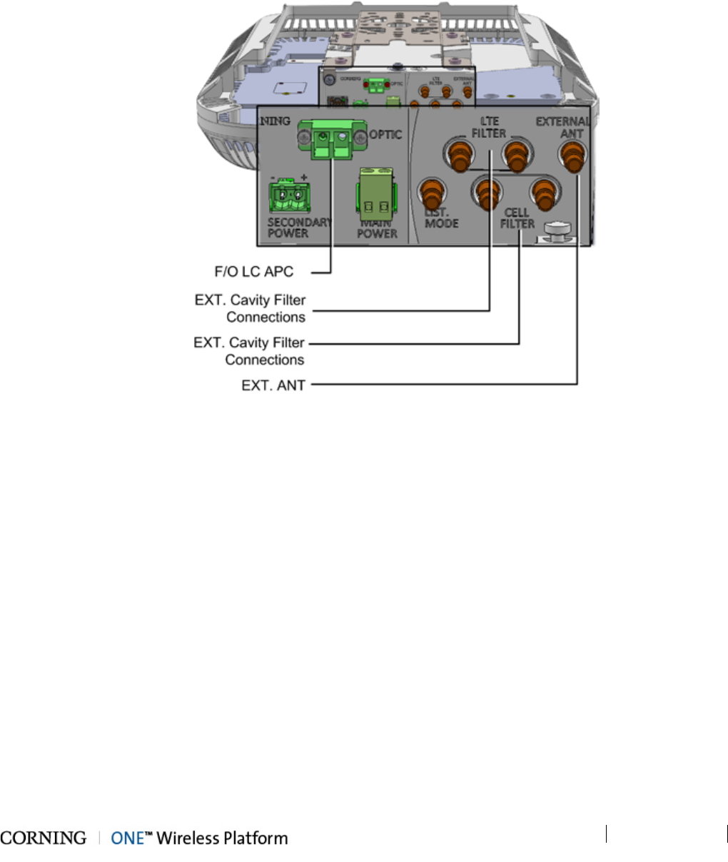
Installation – RF Path Elements P/N 709C011801 Page 107
DRAFT
5. Pull the front panel and remove to access connectors. See Figure 5-64.
6. Connect optic fiber pair to RAU module LC APC connector. See Figure 5-65.
7. RAU optional RF connections:
• EXTERNAL ANT. – for RAU installations above acoustic ceiling requiring external antennas; QMA connector
• RF FILTER – (QMA) External Filter connections (if required by site planner; refer to section 5.2.3).
Figure 5-65. RAU Front Panel Connections
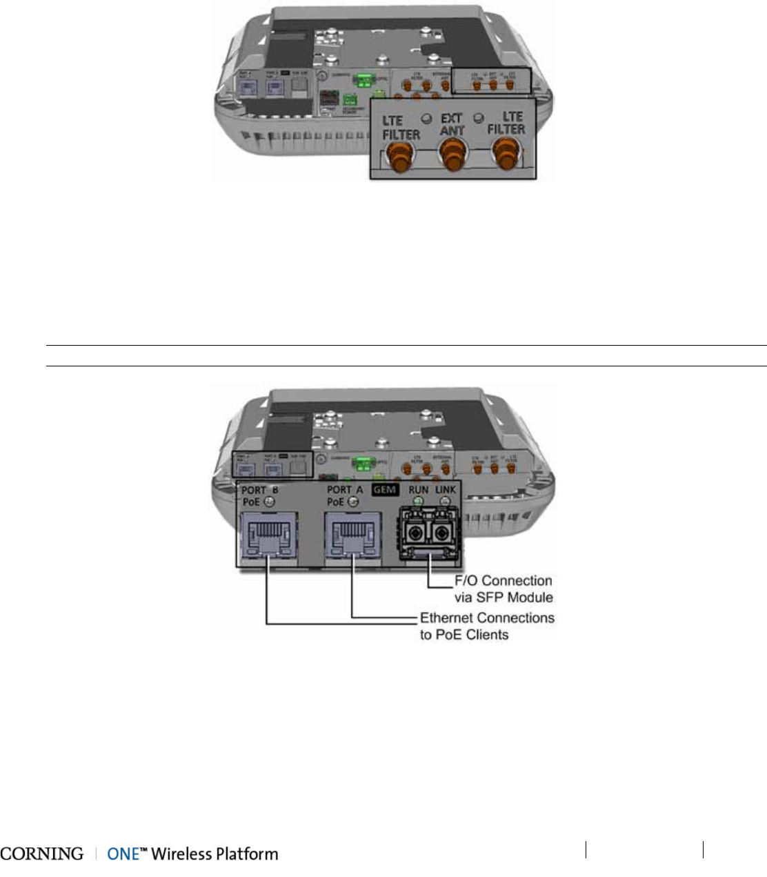
Installation – RF Path Elements P/N 709C011801 Page 108
DRAFT
8. For RAU configurations with RxU module (see Figure 5-66) :
• EXTERNAL ANT. – for installations above acoustic ceiling requiring external antennas; QMA connector;
• RF FILTER – (QMA) External Filter connections (if required by site planner; refer to section 5.2.3)
Figure 5-66. RxU module Interfaces
9. For configurations with GEM module (see Figure 5-71):
• Fiber connections - connect fiber to SFP module ports as follows:
o If using fiber terminated with LC APC (green) – connect to pre-inserted APC to UPC adapters
o If using fiber terminated with LC UPC connector (blue) – remove pre-inserted APC to UPC adapters and connect
directly to SFP module ports
• Connect the A and B Ethernet ports to the PoE clients using Ethernet cables.
Note: A and B Ethernet ports - 10/100/1000BASE-T with 802.3at compliant Power over Ethernet (PoE+) PSE port
Figure 5-67. GEM Module Interfaces (SFP Module Shown without Adapters)
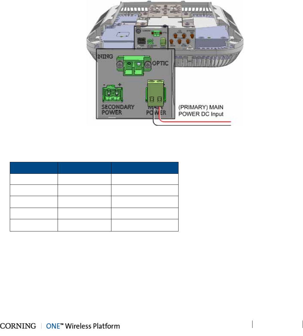
Installation – RF Path Elements P/N 709C011801 Page 109
DRAFT
10. RAU MAIN POWER (for RAU/RAU+RxU) DC input power connections (see Figure 5-68) – connect DC wire pair to the
terminal block connector:
• Power input range: 37 to 57 VDC
• Wire size: 12-30 AWG
• Max. consumption:
o RAU: 35 W
o RAU + RxU: 60 W
o RAU + GEM: 39 W
o RAU + RxU + GEM: 64 W
Figure 5-68. RAU MAIN POWER DC Input Connection
11. For configurations with the GEM module only - power-up and verify normal operation as follows:
A. After the RAU MAIN POWER is connected to the 48V feed, wait 1-2 seconds and verify the status of the GEM LEDs:
LED
Indication
Expected
(GEM) RUN OK/Fault/Run Flashing Amber 1/Sec)
Ethernet LINK Link Off
Ethernet ACT Activity Off
(SFP) LINK Link\Activity Off
PoE PoE Status Steady Amber
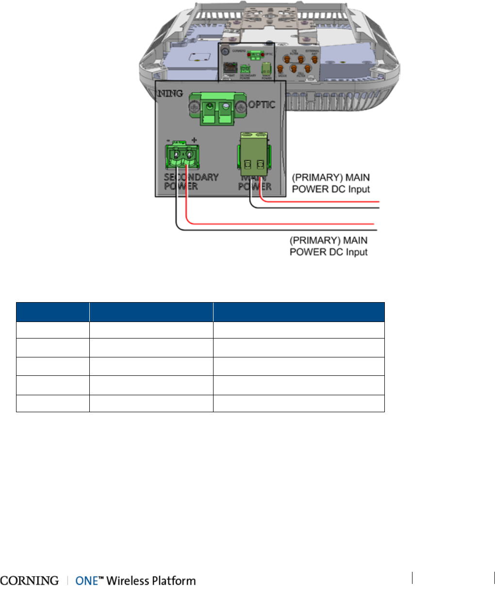
Installation – RF Path Elements P/N 709C011801 Page 110
DRAFT
B. Connect DC wire pair to the RAU SECONDARY POWER DC input connector:
o Wire size: 12-30 AWG
o For 2 PoE ports of 802.3af: 43V; 30 W (Input range: 43 - 57 V DC)
o For 2 PoE ports of 802.3at: 52V; 62 W (Input range: 52 - 57 V DC)
Figure 5-69. RAU MAIN and SECONDARY POWER DC Input Connections
C. After SECONDARY POWER is connected, wait 1-2 seconds and verify GEM LEDs:
LED Behavior Indication
(GEM) RUN Flashing Green (10/Sec) SW and CPU running normally
Ethernet LINK Off Link
Ethernet ACT Off Activity
(SFP) LINK Off Link\Activity
PoE Off POE status
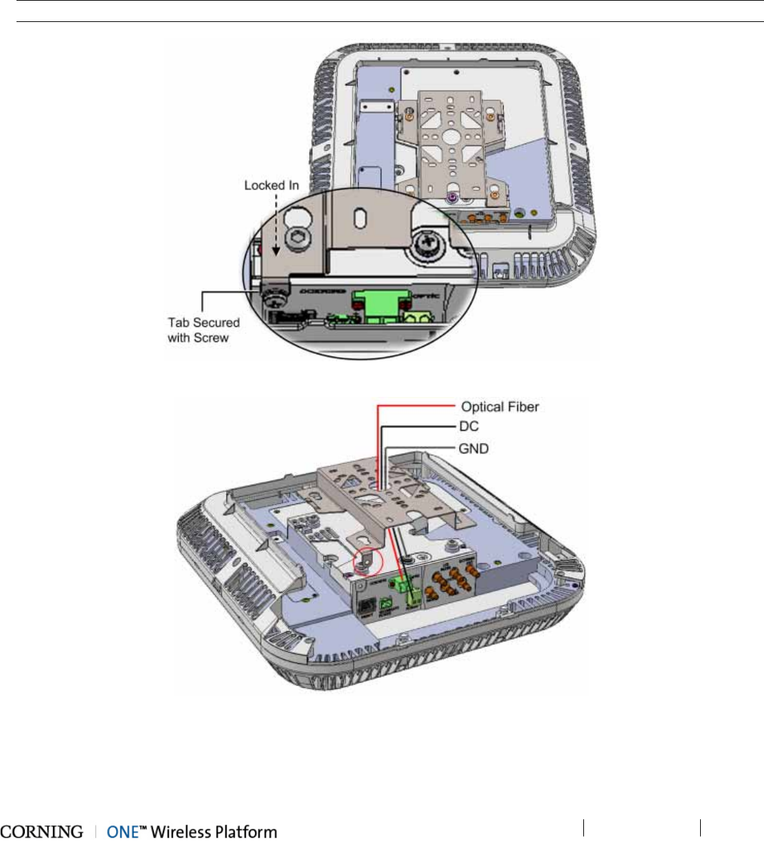
Installation – RF Path Elements P/N 709C011801 Page 111
DRAFT
5.2.2.8 Mounting RAU onto Mounting Bracket
1. For Mid-Mount acoustic ceiling installations (not including installations using the Corning dedicated RAU Mid-Mount
installation option) – attach the RAU Skirt (provided) to the enclosure to cover the rigid edges of the cut-out panel.
2. Referring to Figure 5-71 and Figure 5-70, insert the RAU pins (four) into the bracket key-holes and lock in.
Note: The safety screw tab (circled in Figure 5-71) should be in the same direction of the RAU connectors.
Figure 5-70. RAU and Bracket Assembly
Figure 5-71. Mounting RAU onto Mounting Bracket
3. Secure the bracket safety screw tab to the RAU using an 8-32X3/8, Pan Head, Philips screw (provided). See Figure 5-70.
4. Fit the front panel cover back on.
5. For Acoustic Ceiling Mounts - using the supplied security cable, attach the RAU to a permanent structure within the ceiling
(e.g. acoustic ceiling grid or concrete ceiling above).
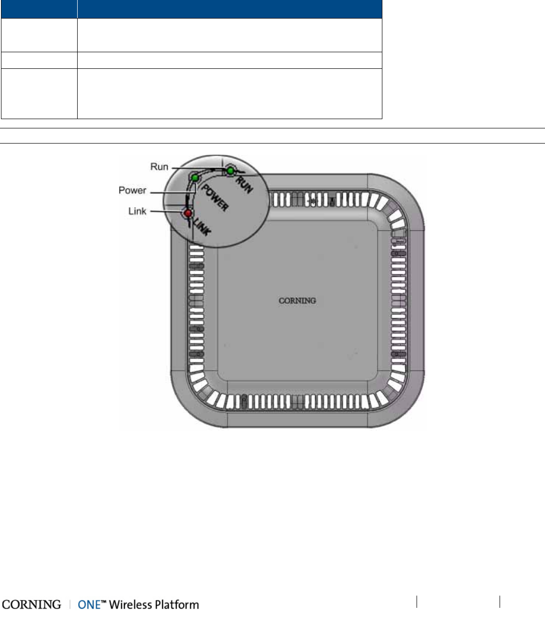
Installation – RF Path Elements P/N 709C011801 Page 112
DRAFT
5.2.2.9 Verify Normal Operation
Verify normal operation via RAU LEDs (located on enclosure cover – see Figure 5-72):
LED Description
LINK RAU Only: Blinking Green
RAU + RxU Installed: Steady Green
POWER Steady Green - Input power within required range detected
RUN Steady Green - Module SW has initialized and is up and running
Blinking Green – Fault detected
Off – Power off
Note: Refer to section 2.3.2 for complete description of LEDs.
Figure 5-72. RAU LEDs
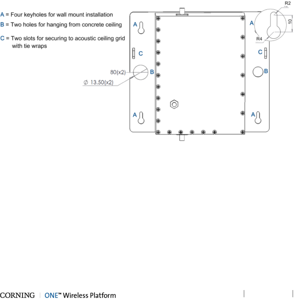
Installation – RF Path Elements P/N 709C011801 Page 113
DRAFT
5.2.3 RAU Cavity Filter Installation
The external cavity filters are required when the RAU/RXU modules supporting the corresponding CELL and LTE bands are
deployed alongside units supporting the public safety service.
• The RAU supports connections to External CELL and LTE Filters
• The RxU supports connections to an External LTE Filter.
• In cases where an LTE External Filter is required and the RAU includes the RxU module – both modules must be connected
to an external LTE filter.
Note the following:
• The Cavity Filter mounting bracket supports wall/ceiling/acoustic ceiling installations. See Figure 5-73.
Figure 5-73.Cavity Filter Dimensions and Mounting Holes
• Consider the length of the RF jumpers (3m) and the distance from the RAU when determining the installation location.
• For acoustic ceiling installations – use provided safety cable to secure the filter assembly to a permanent structure within the
ceiling (e.g. acoustic ceiling grid or concrete ceiling above).
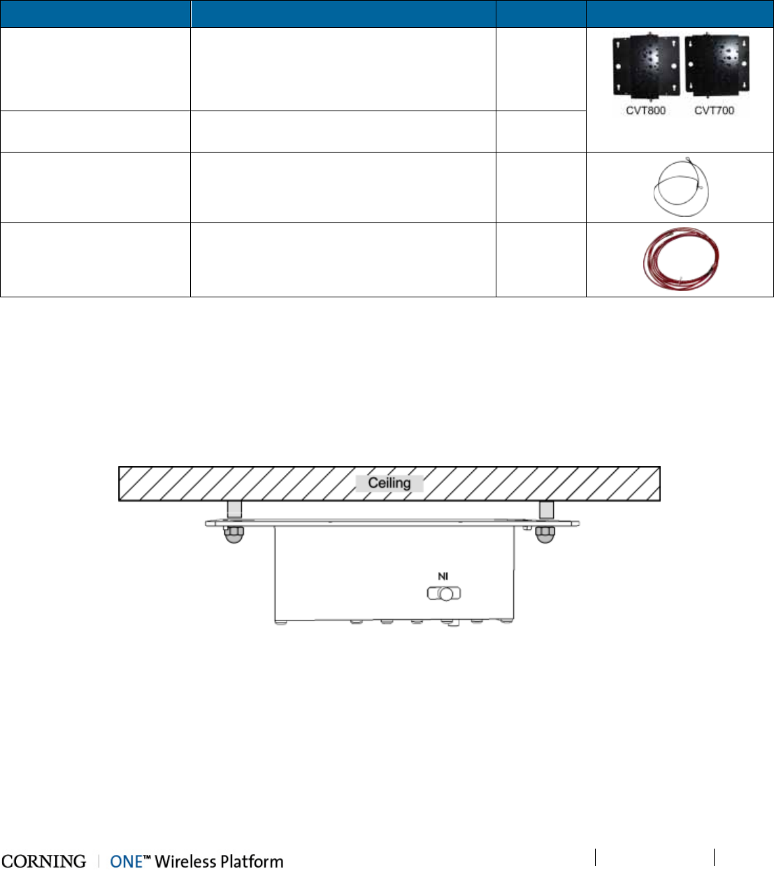
Installation – RF Path Elements P/N 709C011801 Page 114
DRAFT
5.2.3.1 Package Contents
Check your package contents to verify that the items in the packing list are included. If any of the listed items are missing,
contact your Corning representative.
Item Description Quantity
Cavity Filter (depends on
order)
CVT800 - 836.5MHz; 0.5W; 824-849MHz;
IL=1.6 dB max.; SMA
1
CVT700 – LTE; 0.5W; 698-716MHz;
777-787MHz; IL=1.5 dB; SMA
Mounting Bracket Provides wall mount and ceiling mount
installation options (pre-assembled with filter)
1
Safety Cable Required for acoustic ceiling installations 1
RF Jumpers SMA to QMA RF jumpers; L=3m; Used for
RAU/RxU filter connections
2
5.2.3.2 (Concrete) Ceiling Mounting Option
To mount Cavity Filter on Concrete Ceiling
1. Using the two holes (Item B in Figure 5-73) as a guide, mark the location of the holes to be drilled in the ceiling.
2. Drill the holes in ceiling corresponding to the diameter of the toggle anchors to be used (not provided).
3. Mount the Cavity Filter as shown in Figure 5-74.
Figure 5-74. Illustration of Cavity Filter Mounted on Ceiling
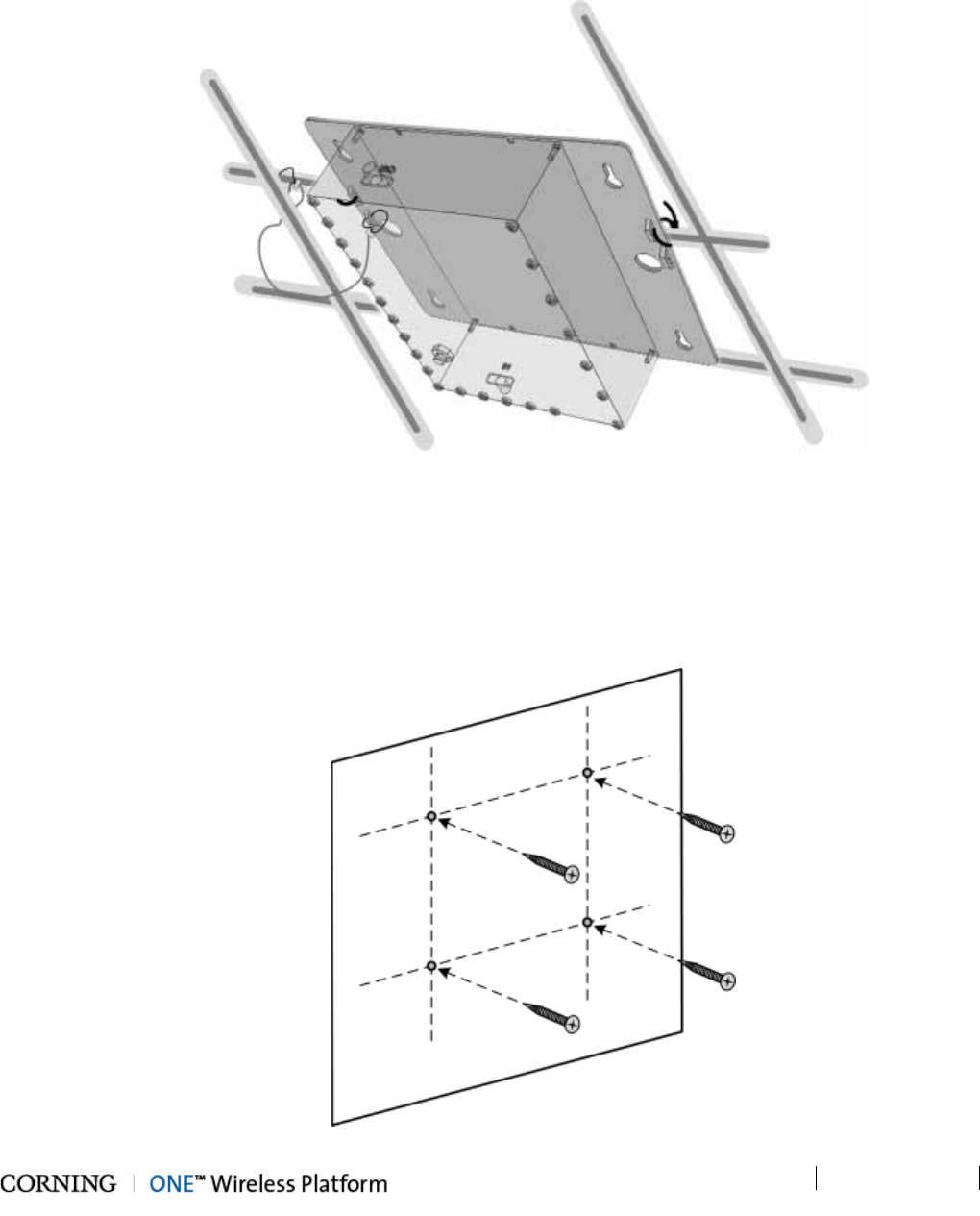
Installation – RF Path Elements P/N 709C011801 Page 115
DRAFT
5.2.3.3 Acoustic Ceiling Mount Installation
In acoustic ceiling mount installations, the Cavity Filter can be fastened to the grid by slipping tie wraps through slits on the
bracket (Item C in Figure 5-73) and securing the assembly to the grid with the provided safety cable. Refer to Figure 5-75.
Figure 5-75. Illustration of Cavity Filter Mounted on Acoustic Ceiling Grid
5.2.3.4 Wall Mount Installation
To mount Cavity Filter on Wall
1. Using the four key holes (Item A in Figure 5-73) as a guide, mark the location of the holes to be drilled in the wall.
2. Drill the holes in the wall corresponding to the diameter of the anchors to be used (not provided).
Figure 5-76. Marking and Inserting Anchors in Wall
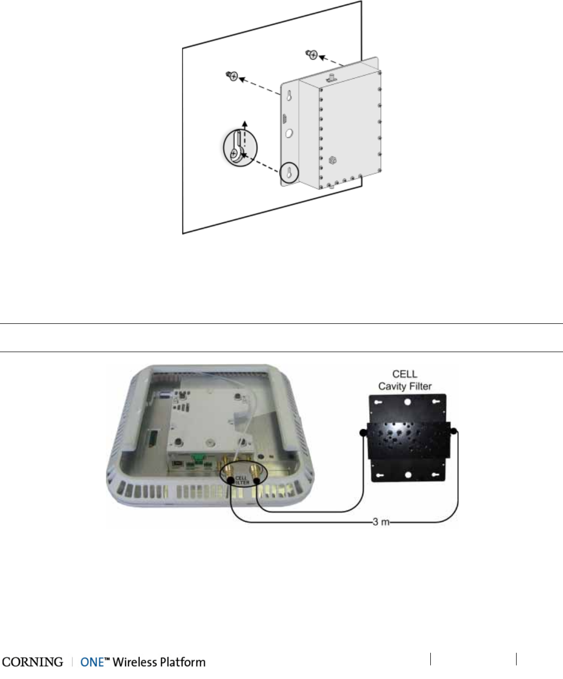
Installation – RF Path Elements P/N 709C011801 Page 116
DRAFT
3. Hang the Cavity Filter on the anchors/screws and pull down to lock in narrow end of key hole. Refer to Figure 5-77.
Figure 5-77. Mounting Cavity Filter on Wall
5.2.3.5 Filter Connections
Using the provided SMA to QMA RF jumpers, connect the Cavity Filter IN and OUT QMA ports to the corresponding filter
(CELL/LTE) SMA connectors on the RAU/RxU module.
Note: In installations where additional units are deployed which support the 700MHz band and the RAU is installed with an RxU
– both RAU and RxU modules must be connected to an external LTE filter. See Figure 5-79.
Figure 5-78. Example of External CELL Filter Connections
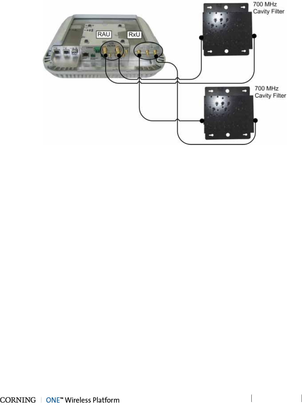
Installation – RF Path Elements P/N 709C011801 Page 117
DRAFT
Figure 5-79. Example of External LTE Filter Connections to RAU and RxU
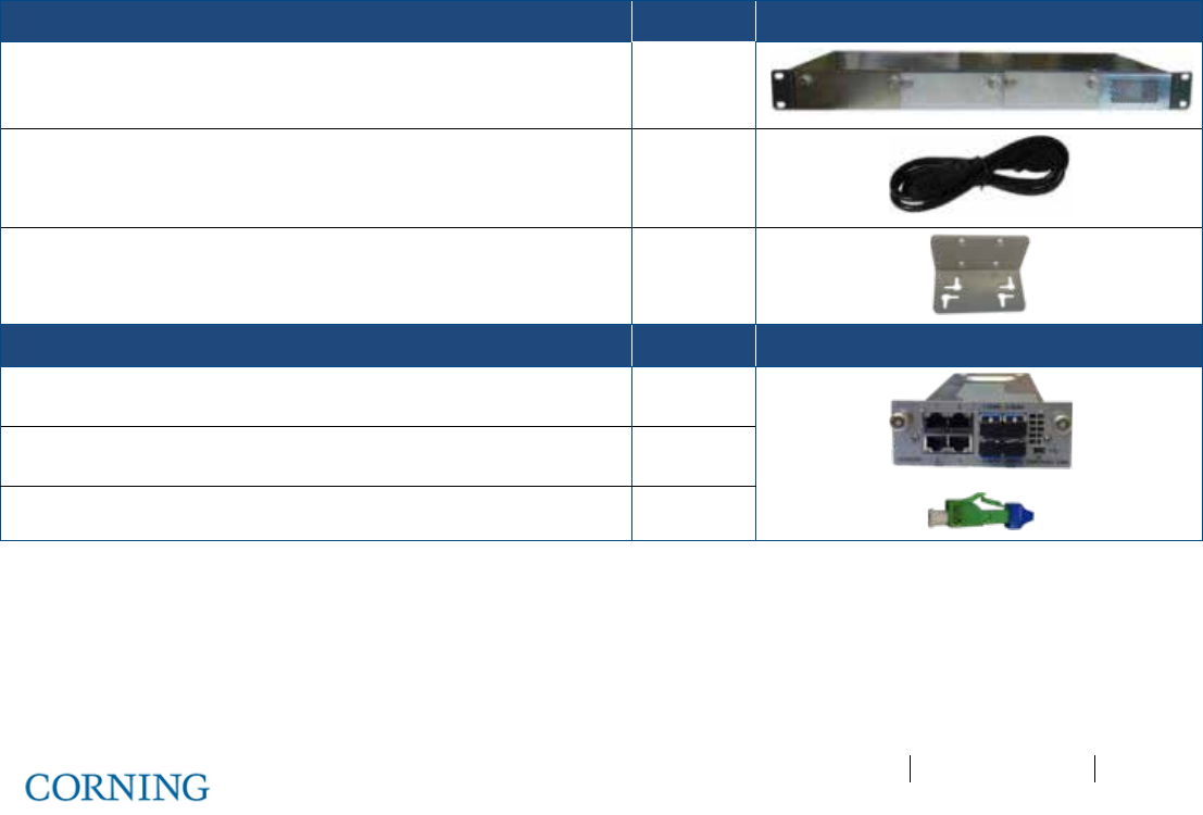
Appendix A: RAU Upgrades P/N 709C011801 Page 118
DRAFT
6 Installation – Digital Coverage Elements
This chapter describes the installation procedures for each of the Digital Coverage components. It contains only brief
descriptions of the approach of each installation procedure. For specific guidelines on infrastructure planning, design and
installation, please consult with a Corning Product Line Manager or Corning approved Installer. All these elements are installed
at the remote end.
6.1 CEU Installation
General Information
• The CEU interfaces to the main Ethernet switch and to the remote Gigabit Ethernet Modules (GEM).
• The CEU is rack mounted or wall mounted at the IDF (Intermediate Distribution Frame).
• The CEU can host up to three Centralized Ethernet Modules (CEMs), which are not included in the CEU package (ordered
separately).
• The CEM Tx/Rx Ethernet fiber ports, used for interfacing to the GEM modules, require SFP modules (included) and LC-UPC
to LC APC adapter if using LC/APC fiber.
6.1.1 Items Required for CEU Installation
The following items are required for installing the ONE™ CEU. If any of the listed items are missing, contact your Corning
representative.
CEU KIT Quantity
Central Ethernet Unit (CEU) with power supply 1
Standard IEC right angle 110-240VAC, 50-60 Hz cable 1
Wall mount brackets 2
CEM KIT Quantity
Central Ethernet Module (CEM) 1
SFP modules (pre-inserted in Tx/Rx ports) 4
ATT. LC/HAP 0dB – used for APC cable 8
Table 6-1. Items Required for CEU Installation
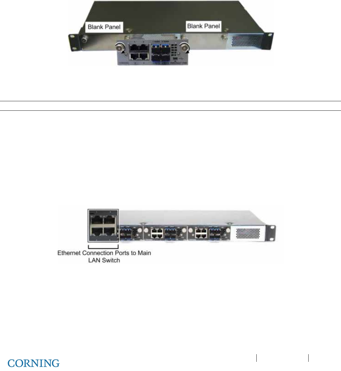
Appendix A: RAU Upgrades P/N 709C011801 Page 119
DRAFT
6.1.2 Installing CEM Module(s)
1. Remove the blank panel.
2. Slide in the CEM and hand tighten the captive screws. Refer to Figure 6-1.
Figure 6-1. Inserting CEM Module(s)
6.1.3 Mounting CEU in 19-IN Rack
Note: Continue to next section if CEU is to be mounted on wall.
Mount the CEU in the 19-in communication rack and secure using pre-assembled brackets.
6.1.4 Mounting CEU on Wall
1. Remove the rack mounting brackets and set aside screws.
2. Assemble wall mount brackets on to the sides of the CEU using the screws.
3. Using the bracket holes as a guide, mark the holes to be drilled on the wall and mount with appropriate screws.
6.1.5 Connecting CEM to Main LAN
Connect any of the CEM RJ45 (1-4) Ethernet ports to the Main LAN Ethernet switch. See Figure 6-2.
Figure 6-2. CEM LAN and Fiber Connection Ports
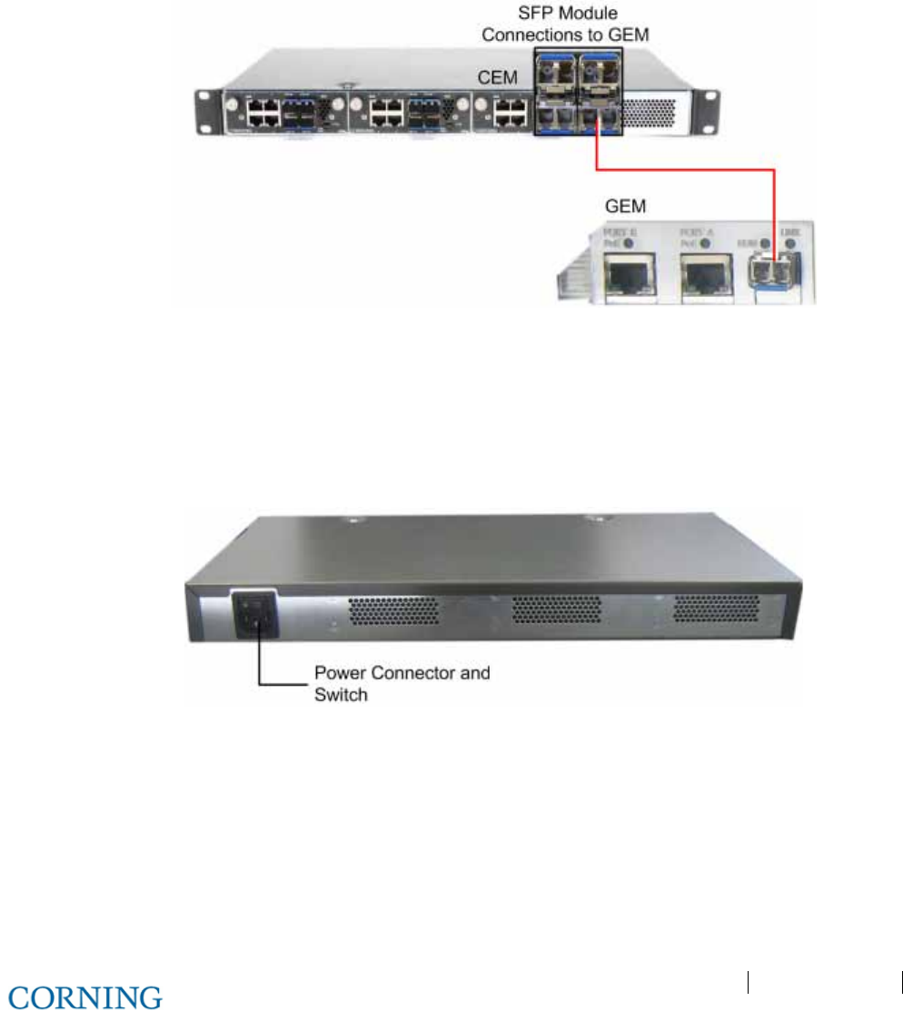
Appendix A: RAU Upgrades P/N 709C011801 Page 120
DRAFT
6.1.6 Connecting Fiber
1. Verify the fiber type:
• If LC/APC (Green), use an LC-APC to UPC adapter
• If LC/UPC (Blue), no adapter is needed
2. Connect the corresponding SFP module connectors (i.e. Tx/Rx port 1 corresponds to fiber port 1) to the GEM LC/APC fiber
connector. See Figure 6-3.
Figure 6-3. CEM to GEM Fiber Connections
6.1.7 Power Up
1. Make sure the power switch is off.
2. Connect supplied 110-240 VAC power cable to the power connector located at the rear of the unit. See Figure 6-4.
3. Switch power on.
Figure 6-4. CEM Power Connector
6.1.8 Verifying Normal Operation Status
Verify F/O, ETH and PWR LED status on CEM module.
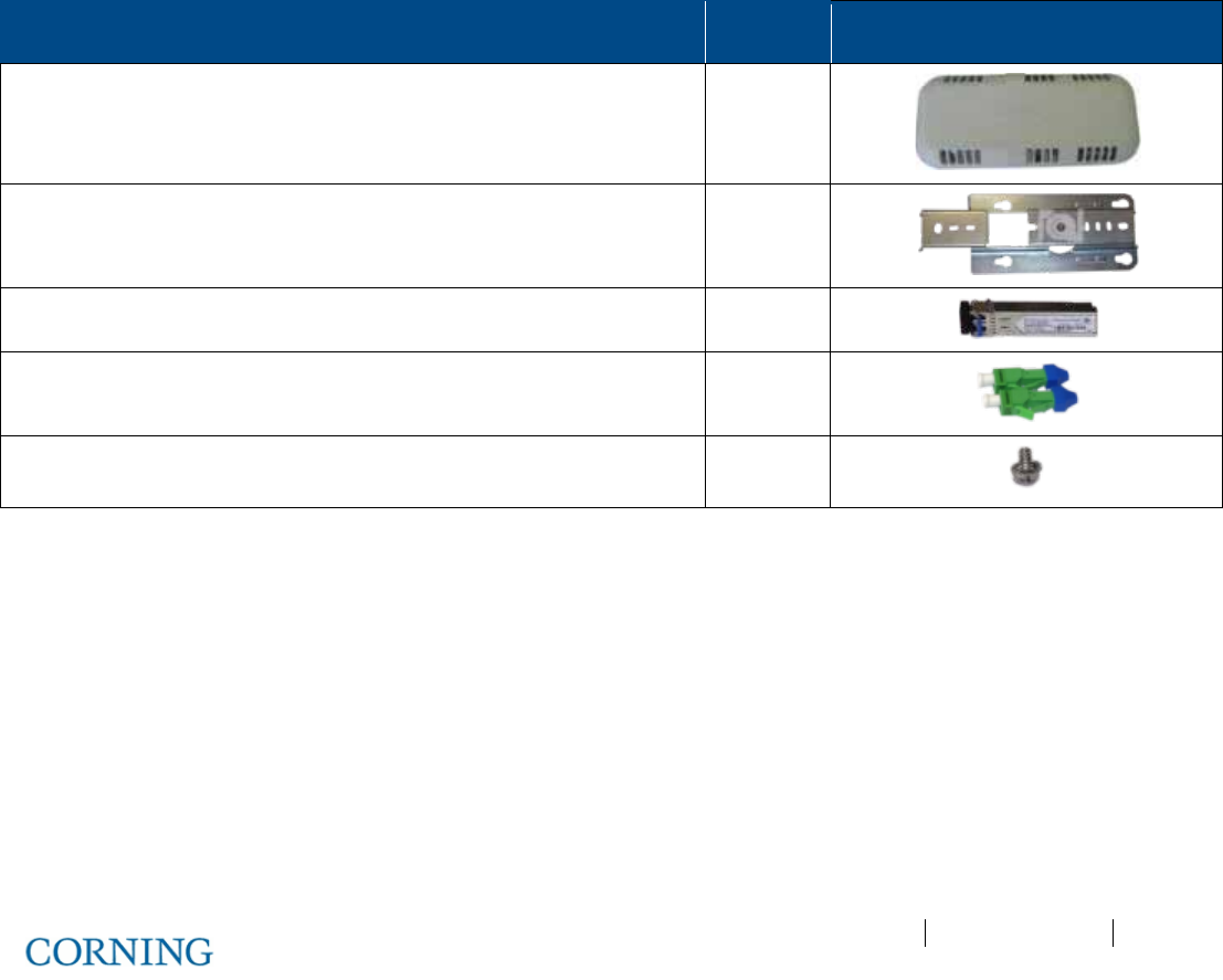
Appendix A: RAU Upgrades P/N 709C011801 Page 121
DRAFT
6.2 GEU-S Installation
This section describes the installation procedure for the GEU-S installed at the remote site.
Note the following:
• The GEU-S unit must always be mounted parallel to the ceiling or wall with a 1-in (minimum) clearance from the surface on
the back and front to allow for proper airflow cooling and heat dissipation.
• The GEU- is provided with a mounting bracket used for mounting on the wall or concrete ceilings (including above acoustic
ceiling mounts). Additional below/mid-mount acoustic ceiling mounting options are possible using a T-Bar mounting bracket
(not provided).
• GEU-S weight: 2.64 lbs (1.2 kg)
6.2.1 Package Contents
Check your package contents to verify that the items in the packing list are included. If any of the listed items are missing,
contact your Corning representative.
Description Quantity
Gigabit Ethernet Unit Standalone (GEU-S) 1
Mounting Bracket with CADDY® “Twist On” Fixture Support 1
SFP – Fiber UPC Module (pre-inserted) 1
UPC to APC Adapter 2
Screw, SEM 8-32X3/8 , Pan Head, Philips - used to secure bracket to
GEU-S
1
Table 6-2.GEU-S Package Contens
6.2.2 Routing Connection Cables
1. Locate DC, fiber, Ethernet and grounding wiring connections.
2. Route the connection cables through the center of the Mounting Bracket. See Figure 6-5.
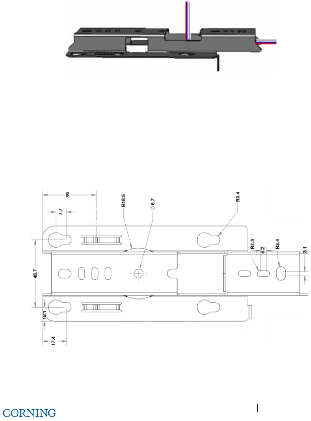
Appendix A: RAU Upgrades P/N 709C011801 Page 122
DRAFT
Figure 6-5: Mounting Bracket on Wall
6.2.3 Installing the Mounting Bracket
Note the following:
• For wall mount installations - GEU-S must be installed parallel to the wall with the connectors facing downwards. See
Figure 6-7
• For above acoustic ceiling installations:
• Allow for at least 1 inch above the acoustic ceiling for air flow cooling.
• Safety screw tab (shown in Figure 6-8) should be positioned to face the same direction as the GEU-S connectors.
• Refer to Figure 6-6 for bracket dimensions.
Figure 6-6: Mounting Bracket Dimensions
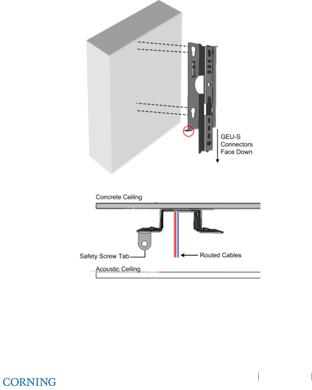
Appendix A: RAU Upgrades P/N 709C011801 Page 123
DRAFT
To install the mounting bracket
Mount the bracket on the wall (Figure 6-7) or concrete ceiling (Figure 6-8) using any of the screw hole sets and the appropriate
screws (not provided).
Figure 6-7: Mounting Bracket on Wall (Routed Cables Not Shown)
Figure 6-8: Bracket Installation and Routed Cables
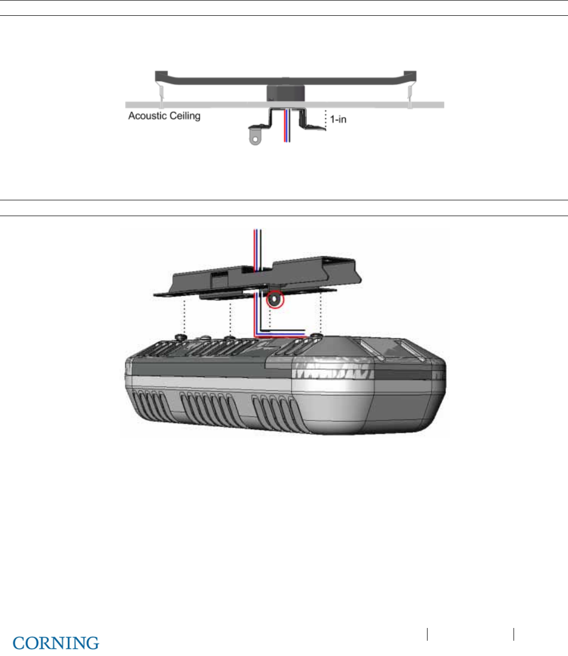
Appendix A: RAU Upgrades P/N 709C011801 Page 124
DRAFT
6.2.4 Additional Bracket Installation Options
Note: A T-Bar Mounting Bracket can be used (not provided) to mount the GEU-S below an acoustic ceiling.
1. Referring to Figure 6-9, install the T-Bar on the ceiling above the acoustic tiles (according to manufacturers’ instructions).
2. Make sure to allow for a minimum of 1-in between ceiling tile and GEU-S.
Figure 6-9: Below Ceiling Installation
3. Route the connections cables through the center of the GEU-S Mounting Bracket.
Note: The safety screw tab (circled in Figure 6-10) should face the same direction as the GEU-S connectors.
Figure 6-10: Routing Cables and Mounting GEU-S on Bracket
4. Install GEU-S bracket on the T-Bar, using any of the appropriate bracket installation holes.
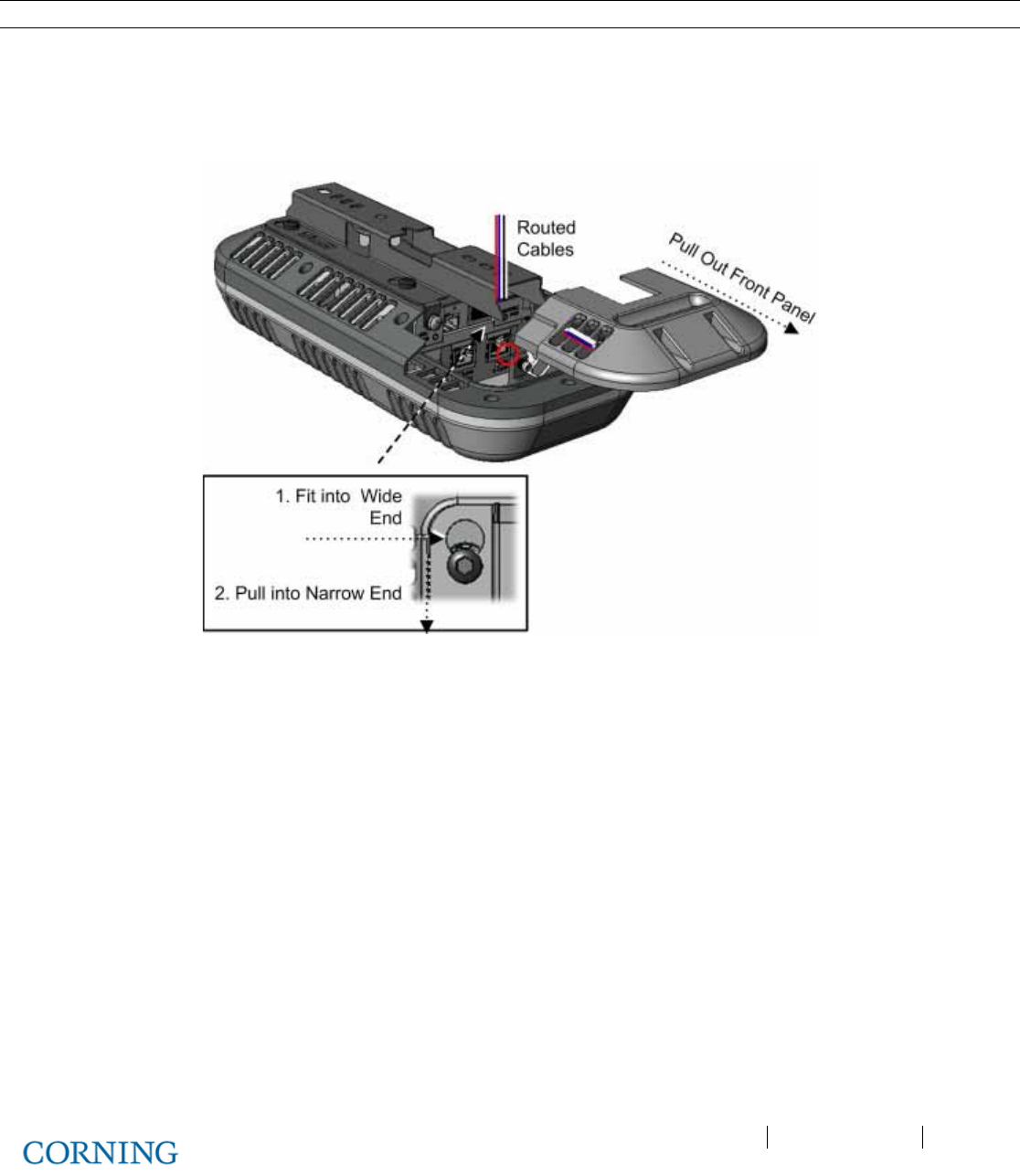
Appendix A: RAU Upgrades P/N 709C011801 Page 125
DRAFT
6.2.5 Assembling the GEU-S onto the Bracket
Note: The safety screw tab (circled in Figure 6-11) should be in the same direction of the connectors.
1. Hold the GEU-S near the mounting bracket and routed cables.
2. Route the cables towards the front panel connectors, where the bracket will be located as shown in Figure 6-11.
3. Insert the four GEU-S pins into the wide end of the bracket holes and then pull towards the narrow end to lock in.
4. Using the provided screw (SEM 8-32X3/8), secure the bracket to the GEU-S via the safety screw tab.
Figure 6-11: Locking GEU-S
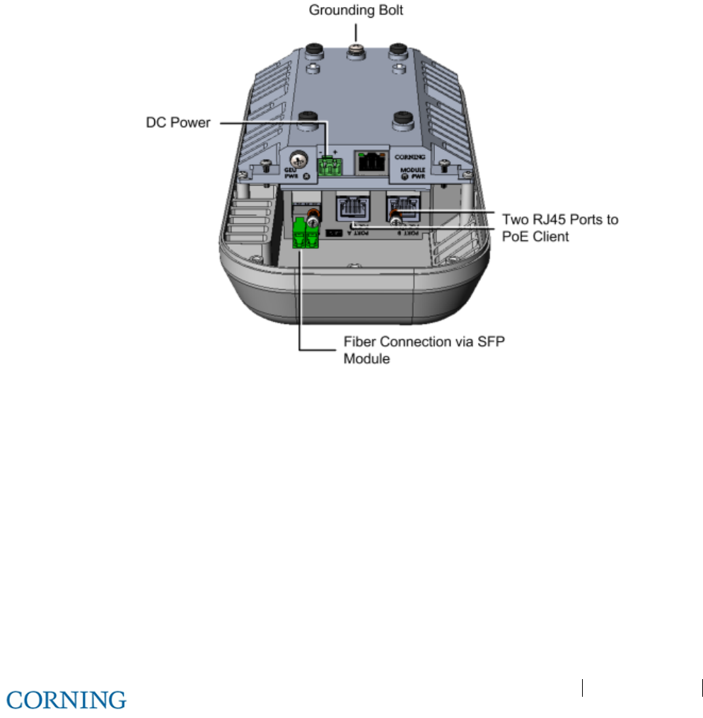
Appendix A: RAU Upgrades P/N 709C011801 Page 126
DRAFT
6.2.6 Connecting Cables
Referring to Figure 6-12, connect as follows:
1. Pull out front panel cover to access connectors. See Figure 6-11.
2. Connect the optic fiber to the SFP module:
• Fiber terminated with LC UPC connector (blue) – connect directly to SFP module
• Fiber terminated with LC APC (green) – connect using the provided APC to UPC adapters
3. Connect the RJ45 PoE output ports to (2) PoE clients using Ethernet cables.
4. Reach under bracket, and connect the earth ground to the GEU-S grounding bolt (32 x 3/8 screw).
5. Connect DC wire pairs (46 – 57 VDC).
Figure 6-12: GEU-S Connection Ports (Bracket Not Shown)
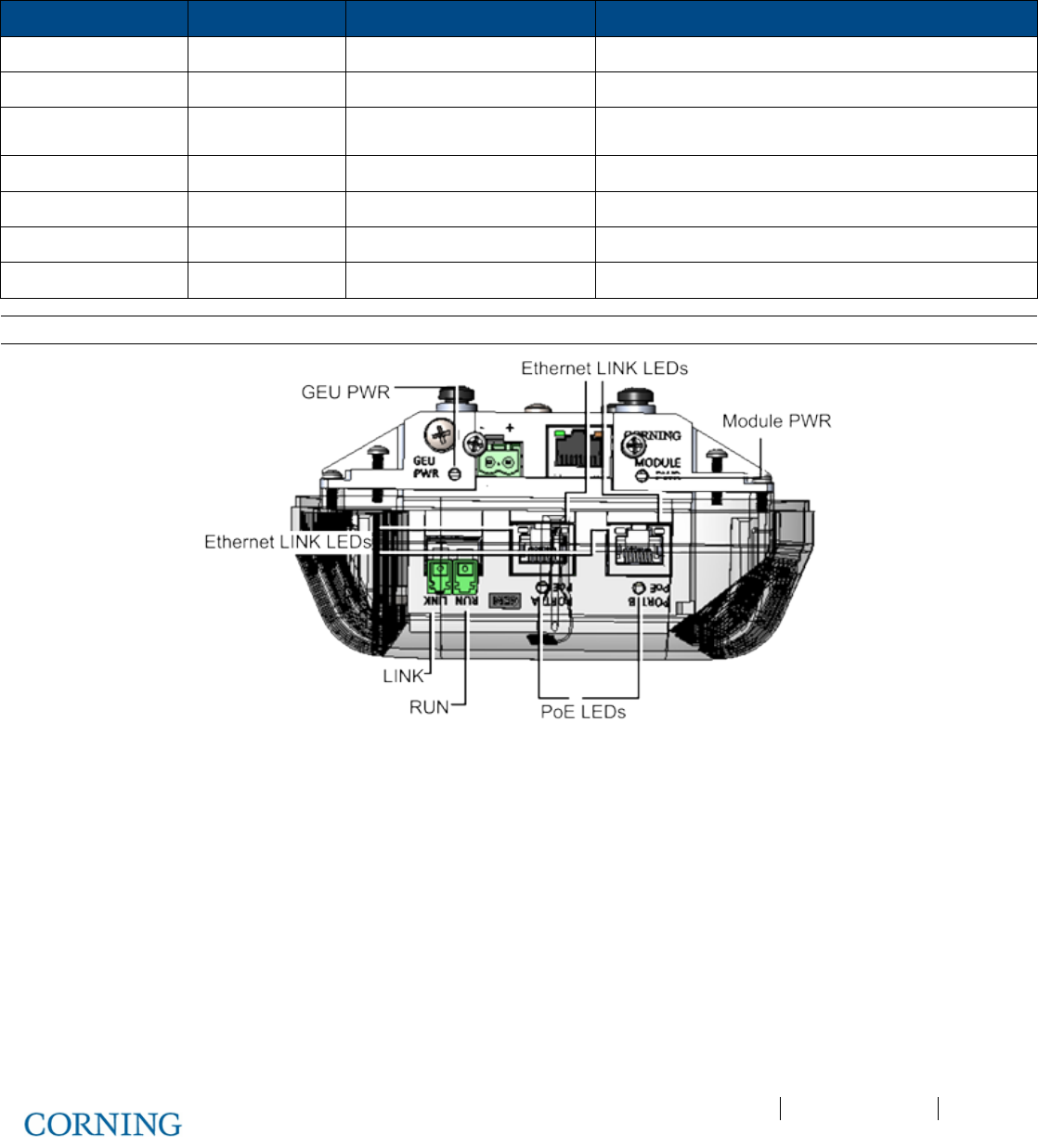
Appendix A: RAU Upgrades P/N 709C011801 Page 127
DRAFT
6.2.7 Verify Normal Operation
Referring to Figure 6-13, verify normal operation via GEU-S (GEM and GEU modules) LEDs - located adjacent to the respective
connectors:
LED Indication Expected Description of expected indication
RUN OK\Fault\Run Flashing
GREEN
(10/Sec) SW & CPU running normally, GEM OK, no Fault
Ethernet LINK Link Off
Ethernet ACTIVITY Activity Off
SFP LINK link from CEU Off
POE POE status Off 48V feed to PoE circuitry exist and PoE OFF
GEU PWR GEU power Steady
GREEN
GEU input power detected
Module PWR module power Steady
GREEN
GEU input power detected
Note: For complete description of GEM and GEU-S LEDs, refer to section 3.3 (GEM) and 3.4 (GEU-S).
Figure 6-13: GEU-S LEDs
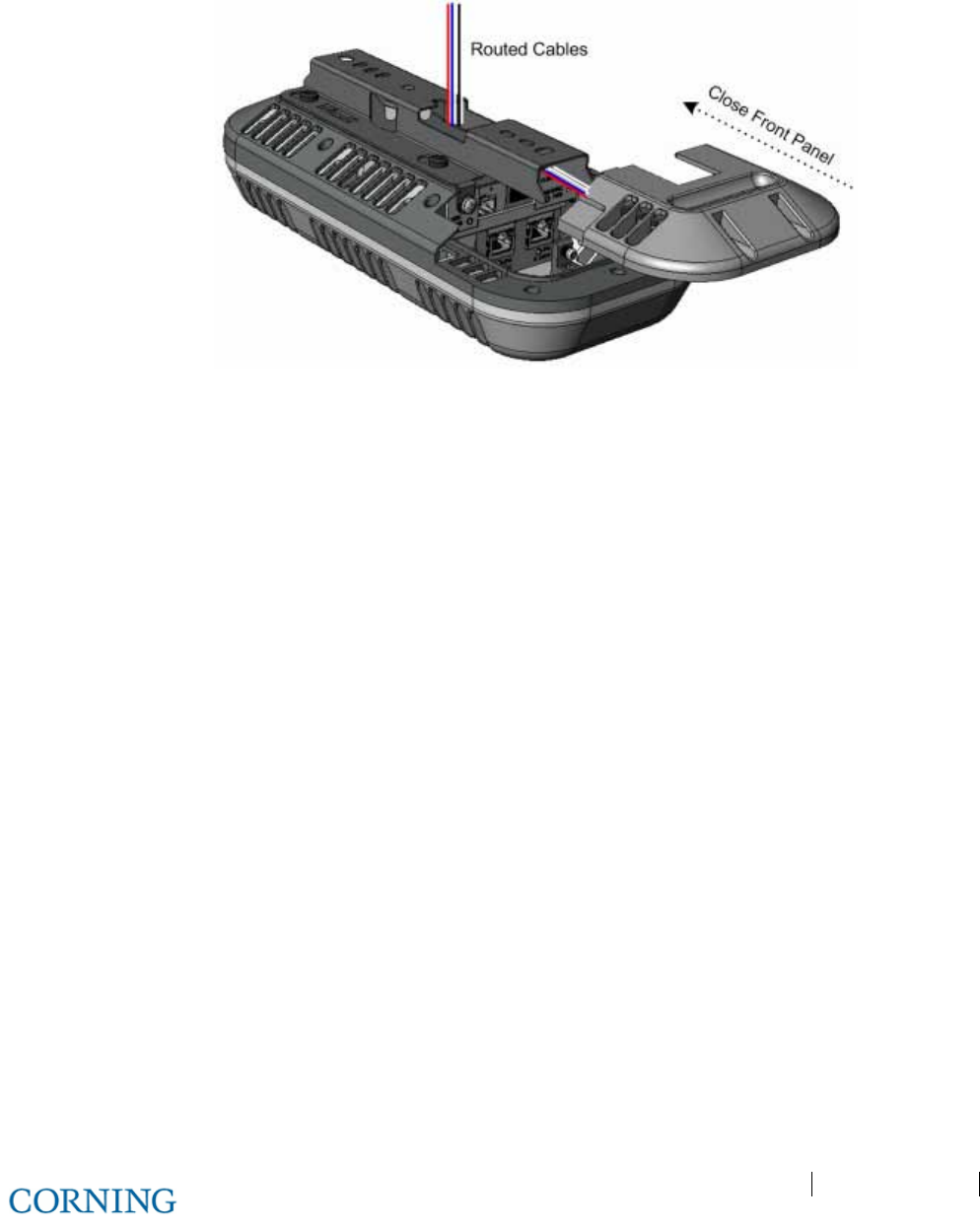
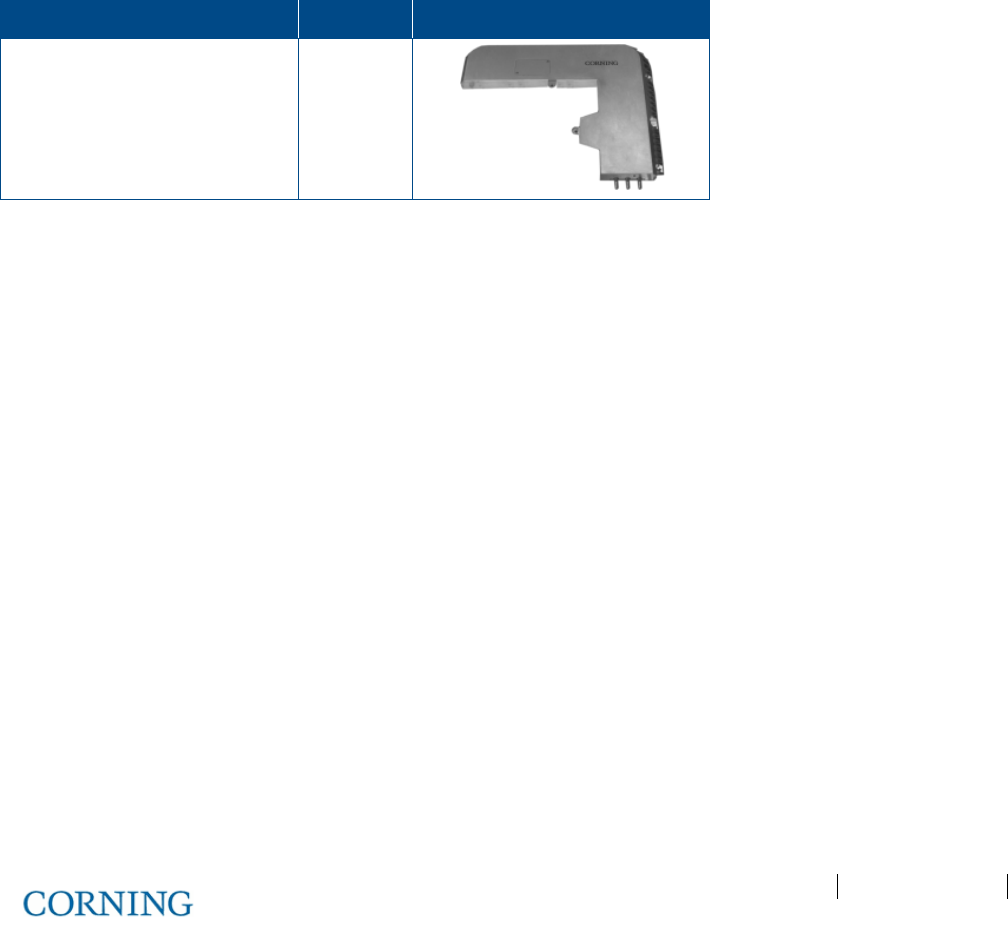
Appendix A: RAU Upgrades P/N 709C011801 Page 129
DRAFT
Appendix A: RAU Upgrades
Upgrading RAU with an RxU
This section describes how to upgrade an RAU with an RxU, providing MIMO support for the LTE700 and AWS bands..
General Information
• The RxU expands the RAU band support to additional two MIMO bands.
• The RxU can either be pre-installed in the RAU module (according to order) or easily added at a later stage when required.
• The installation of the RxU module is hot-swappable and does not require disconnecting cables or power.
Package Contents
Check your package contents to verify that the items in the packing list are included. If any of the listed items are missing,
contact your Corning representative.
Item Quantity Image
Remote Expansion Unit (RxU) 1
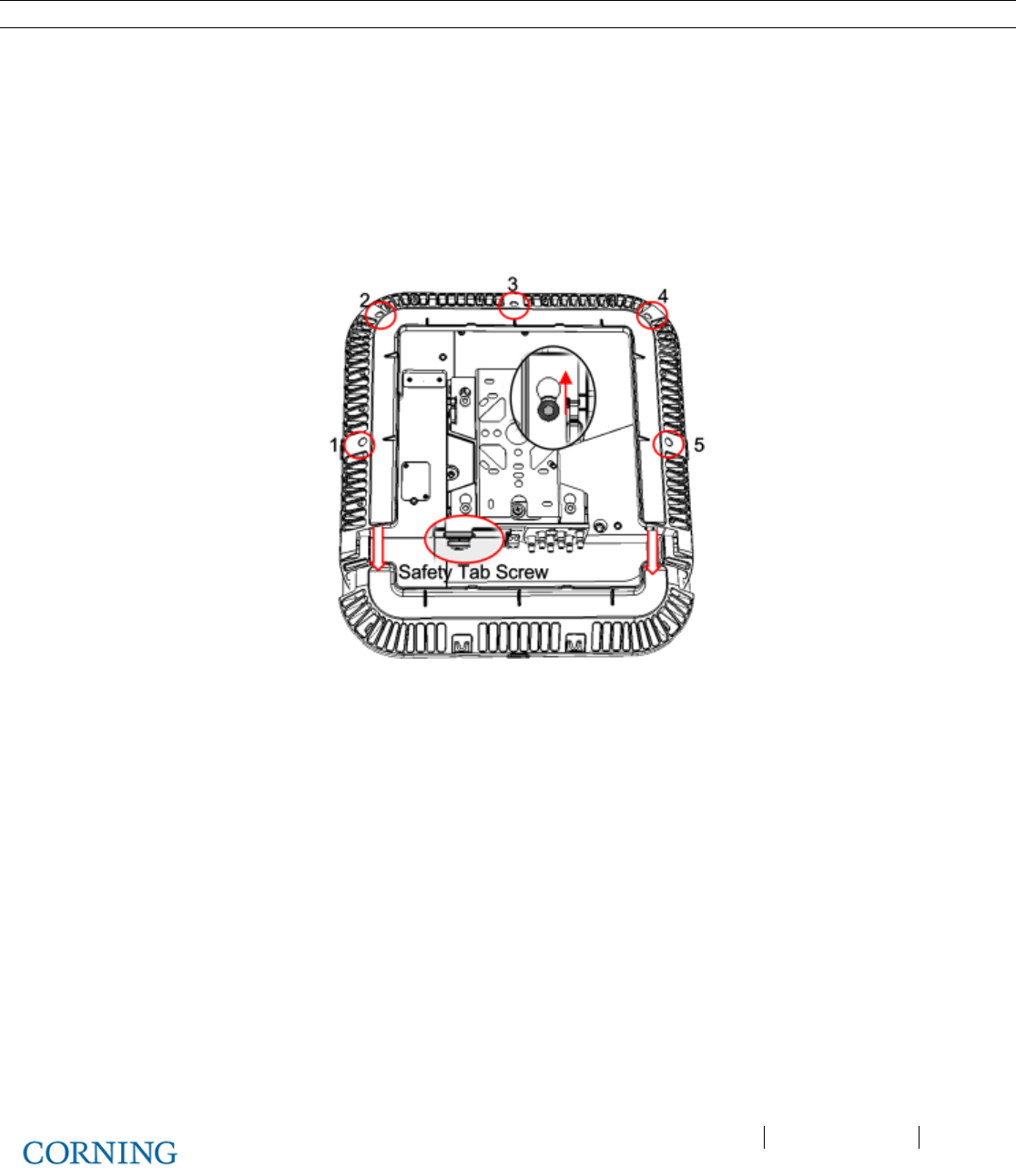
Appendix A: RAU Upgrades P/N 709C011801 Page 130
DRAFT
Installing the RxU Module in the RAU
Note: There is no need to disconnect the cables leading from the ceiling.
To install RxU module in RAU enclosure:
1. Referring to Figure 6-15, remove RAU enclosure cover:
A. Remove the Safety Tab Screw, securing the bracket to the RAU (located above MGMT port).
B. Slide the RAU back into wide end of bracket screw holes, so that it “clicks” and remove unit.
C. Unscrew (5) screws securing the RAU enclosure cover and remove cover..
D. Remove front flap in direction of arrows.
Figure 6-15. Removing RAU Enclosure Cover
2. Assemble the RxU in the RAU enclosure:
A. Plug the RxU in to the right side of the RAU as indicated in Figure 6-16.
B. RxU and RAU interface ports should face the same direction.
C. Replace the cover except for the front access panel.
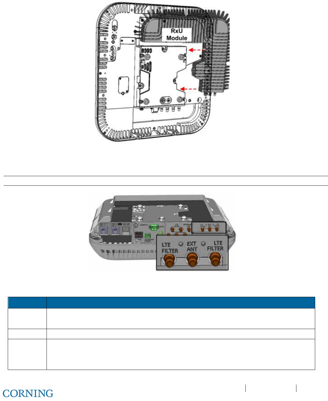
Appendix A: RAU Upgrades P/N 709C011801 Page 131
DRAFT
Figure 6-16. RxU Module Assembly
3. If required by site planner - connect the filter to the RF filter connectors on the RxU. Refer to Figure 6-17 for location of RxU
filter connections.
Note: Refer to section 5.2.3 for Cavity Filter installation and connections.
Figure 6-17. Assembled RxU Interfaces
4. Verify that RAU LEDs on, on front cover (see Figure 6-18) indicate normal operation status:
LED Description
LINK Steady Green - Optical link power to/from the connected remote is normal
Blinking Green - Optical power is lower than required
POWER Steady Green - Input power within required range detected
RUN Steady Green - Module SW has initialized and is up and running
Blinking Green – Fault detected
Off – Power off
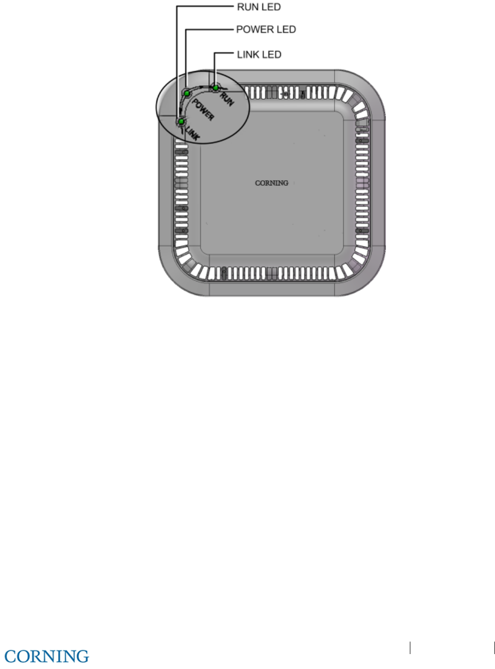
Appendix A: RAU Upgrades P/N 709C011801 Page 132
DRAFT
Figure 6-18. RAU Enclosure LEDS
5. Assemble RAU front access panel and remount.
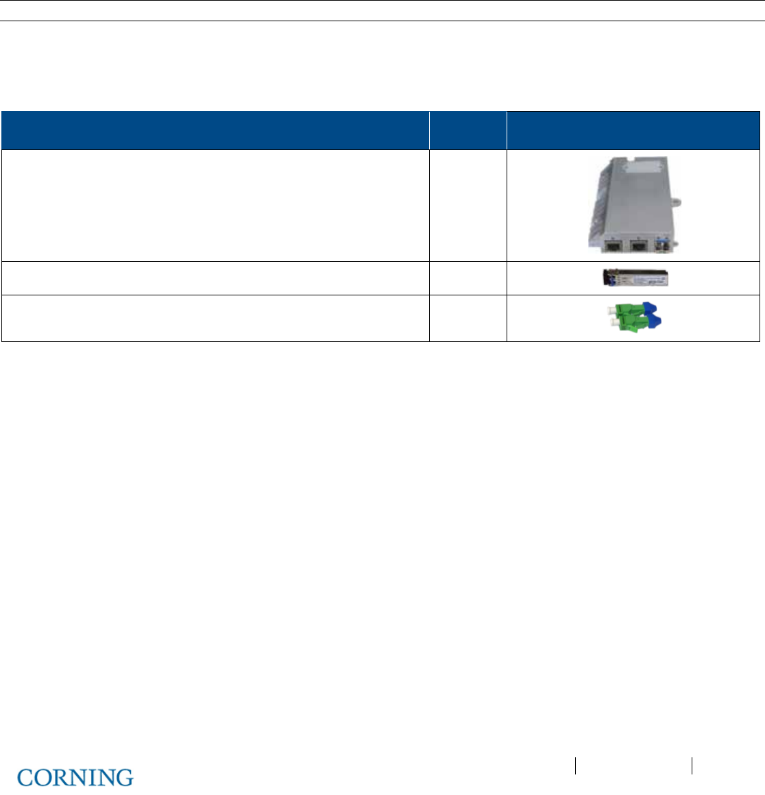
Appendix A: RAU Upgrades P/N 709C011801 Page 133
DRAFT
Upgrading RAU GEM Installation (Upgrade)
The GEM module provides Ethernet Data coverage distributed through 3rd party equipment - supports PoE connection for up to
two Access Points (APs).
This section describes how to upgrade an RAU with a GEM module enabling the distribution of RF and Ethernet data coverage
from a single unit.
Note: If digital coverage is required during Greenfield deployment then the GEM is pre-installed in the RAU.
Package Contents
Check your package contents to verify that the items in the packing list are included. If any of the listed items are missing,
contact your Corning representative.
Description Quantity
Gigabit Ethernet Module (GEM) 1
SFP – Fiber UPC Module (pre-inserted) 1
UPC to APC Adapter 2
Table 6-3.GEM Package Contents
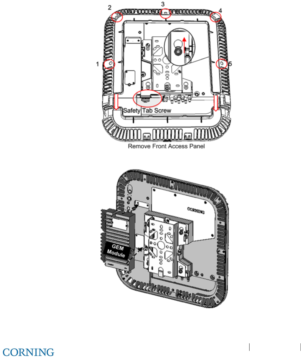
Appendix A: RAU Upgrades P/N 709C011801 Page 134
DRAFT
Installing the GEM module in the RAU
1. Remove RAU front panel and then cover by removing the five screws indicated in Figure 6-19
2. Plug GEM into the left side of the RAU, as shown in Figure 6-20 and secure (4) GEM screws.
3. Replace the cover except for the front panel so that the interface ports are accessible, as shown in Figure 6-21.
Figure 6-19. Removing RAU Enclosure Cover
Figure 6-20. GEM Module Assembly
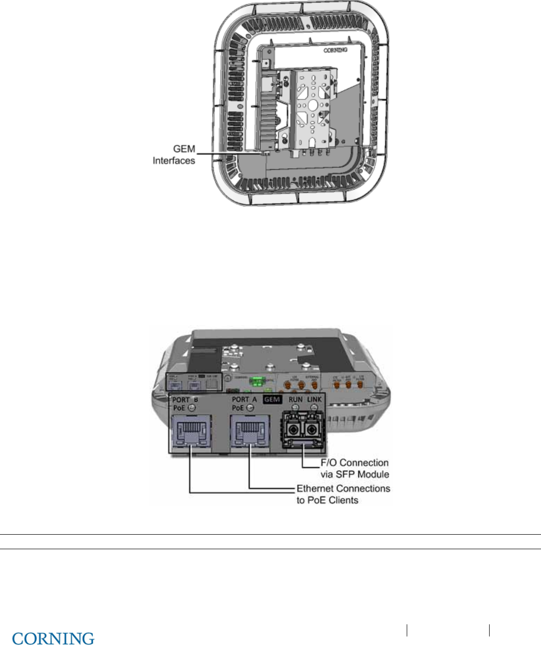
Appendix A: RAU Upgrades P/N 709C011801 Page 135
DRAFT
Figure 6-21. RAU and GEM with Assembled Cover
4. Connect the cables as follows:
A. Connect the fiber to the SFP module (pre-inserted in F/O port):
o Fiber terminated with LC UPC connector (blue) – connect directly to SFP module
o Fiber terminated with LC APC (green) – connect using the provided APC to UPC adapters
B. Connect the A and B Ethernet ports to the PoE clients using Ethernet cables. See Figure 6-22.
Figure 6-22. GEM Interface Ports and LEDs
Note: A and B Ethernet ports - 10/100/1000BASE-T with 802.3at compliant Power over Ethernet (PoE+) PSE port
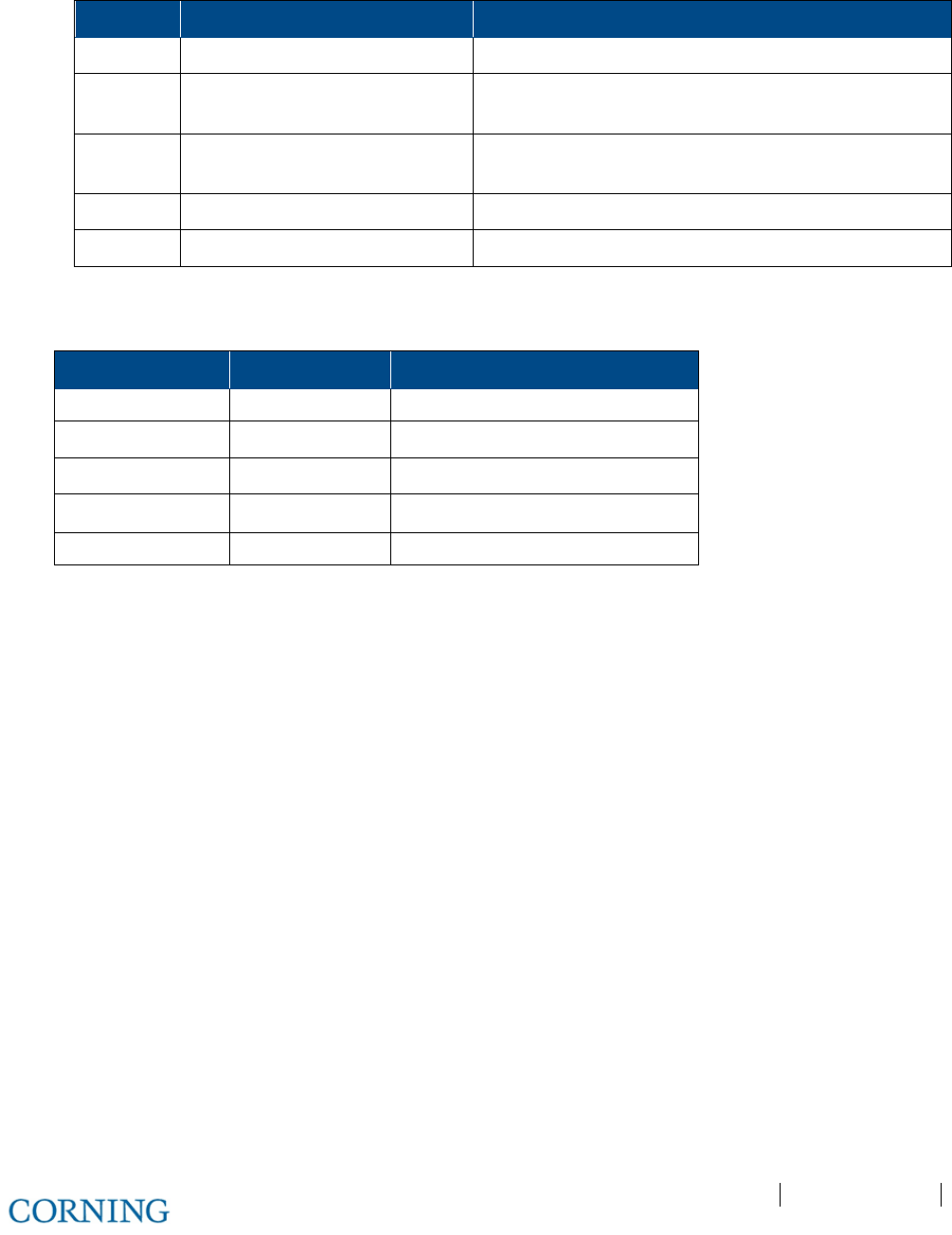
Appendix A: RAU Upgrades P/N 709C011801 Page 136
DRAFT
C. Connect the Secondary 48V feed to the RAU and Wait 1-2 seconds. Verify status of GEM LEDs according to Table 6-4:
LED Expected Description of expected indication
RUN Flashing
GREEN
(10/Sec) SW and CPU running normally
Ethernet
LINK
Off
Ethernet
ACTIVITY
Off
SFP LINK Off
POE Off 48V feed to PoE circuitry exist and PoE OFF
Table 6-4.GEM Secondary Power LED Status
D. After SECONDARY POWER is connected, wait 1-2 seconds and verify GEM LEDs:
LED Indication Expected
(GEM) RUN OK Flashing Green (10/Sec)
Ethernet LINK Link Off
Ethernet ACT Activity Off
(SFP) LINK Link\Activity Off
PoE POE status Off

Appendix B: Specifications P/N 709C011801 Page 137
DRAFT
Appendix B: Specifications
Supported Services
Technology
Frequency Range (MHz)
Service/Band Uplink (UL) Downlink (DL)
LTE 700 MHz 698-716
777-787
728-746
746-756
CDMA/WCDMA**/ TDMA/GSM/LTE* CELL 800 824-849 869-894
CDMA/WCDMA**/TDMA/GSM/LTE* PCS 1900 1850-1915 1930-1995
WCDMA**/LTE* AWS 2100 1710-1755 2110-2155
*WCDMA service is based on 3GPP standards, LTE service may deployed in the future due to Frequencies re-farming planned by the Carriers as well
**WCDMA service is based on 3GPP2 CDMA2000 standards.
RF Parameters per Service
Service/Band LTE
700 MHz
CELL
800 MHz
PCS
1900 MHz
AWS
2100 MHz
RF Parameter DL UL DL UL DL UL DL UL
Frequency Range
(MHz)
728-746
746-756
698-716
777-787 869-894 824-849 1930-1995 1850-1915 2110-2155 1710-1755
Max Output Power Per
Antenna Port (dBm)
14 14 17 18
Max Input Power (dBm)
0 to 37 0 to 37 0 to 37 0 to 37
Mean Gain (dB)
-19 to 10 -19 to 10 -19 to 10 -19 to 10
Input IP3 (dBm) AGC
OFF Min
-5 -5 -5 -5
Input IP3 (dBm) AGC
ON Min
5 5 5 5
SFDR** (dB)
59 63 63 59
Max Intermod
Distortion (dBm)
-13 -13 -13 -13
UL NF*(dB)
12 12 12 12
Gain Flatness/Ripple
(dB)
±2.0 ±2.0 ±2.0 ±2.0
*Typical for single remote antenna
** SFDR calculated with BW of 1.23MHz for the CELL and PCS and with 5MHz for the LTE and AWS

Appendix B: Specifications P/N 709C011801 Page 138
DRAFT
Environmental, Standards and Optical
Environmental
Operating Temperature 0°C to +50°C (32°F to 122°F)
Storage -20°C to 85°C (-4°F to 185°F)
Standards and Approvals
Laser Safety FDA/CE 21 CFR 1040.10 and 1040.11 except for deviations pursuant to laser notice no.
50 and IEC 60825-1
EMC CE EN 301 489, EN55022, EN 61000
FCC 47 CFR Part 15, 22, 24, 27
Safety UL 60950
IEC 60825-1:2007
IEC 60825-2:2010
CAN/CSA-C22.2 No.60950-1-03
Fire Safety UL 2043 (applicable for Access Unit only)
Optical
Optical Output Power < 9 dBm
Max. Optical Budget 5 dB
Optical Connector OIM: Female MTP® connector;
RAU: LC APC SM
Fiber Type Corning® SMF-28® fiber or compatible
Wavelength 1310 ± 10 nm (@ 25◦ C)
Maximum Distance
(Headend to Remote)
2 km (SMF)
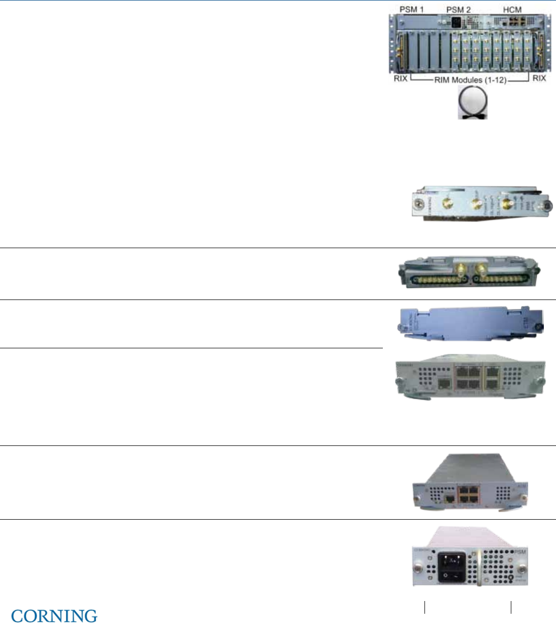
Appendix B: Specifications P/N 709C011801 Page 139
DRAFT
RF Path: Coverage Component Specifications
Headend Unit (HEU)
HEU will host the following modules:
1. RIM - Radio Interface Module; RF source conditioner.
Up to 12 RIMs can be hosted by the HEU.
2. RIX - Radio Interface Expander; HEU to OIU interface module
Note: For configurations with one RIX an ETM is required for terminating the
unused Expander slot.
3. HCM - Headend Control Module; overall system management module
4. ACM – Auxiliary Control Module; provides interfaces for management of
domestic modules via HCM; installed in HEUs’ in configurations with more than
one HEU
5. PSM - Power Supply Module; AC or DC Power Supply
6. ERFC - RF interface cable, 9-PIN (various cable lengths available)
RIM
Interfaces: Three QMA RF ports; UL, DL and
Duplex
No. of supported
bands:
Single band
RIX
Interfaces: Two 9-pin connectors (one per OIX)
No. of supported OIU
interfaces:
Two OIUs
ETM
ETM (Expander Termination Module) - used for terminating
unused Expander slot
HCM
Interfaces: To four ACM RJ-45 INTERNAL ports
Remote Management: One RJ-45 LAN port
Local Management: One RJ-45 LOCAL port
Local Configuration: One CONSOLE port
System LEDs: PWR, RUN, SYS, FAN
ACM
Interfaces:
Four RJ-45 INTERNAL ports
One RJ-45 CONSOLE port
System LEDs – PWR, RUN, SYS, FAN
PSM-AC
Power Input:
100-220 V AC
Power Consumption
(Full Chassis):
300 W
ON/Off Switch
Optional: Additional PSM-AC for redundancy
ERFC
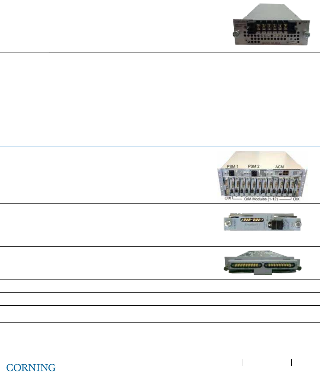
Appendix B: Specifications P/N 709C011801 Page 140
DRAFT
Headend Unit (HEU)
(continued)
PSM-DC
Power Input: 48 V DC; 9 A Max.
Power Consumption
(Full Chassis):
200 W
Connector: Six pin terminal block connector
Optional: Additional PSM for redundancy
Physical
Characteristics
(Chassis +
Modules)
Mounting: Rack-mount – 19 in and 4U
Dimensions
(H x W x D):
7 x 17.3 x 18.95 in (177.8 x 440 x 481.7 mm)
Weight: Chassis: 37 lbs (16.8 kg)
Per RIM: 1.9 lbs (0.9 kg)
Per RIX: 1.54 lbs (0.7 kg)
HCM: 2.2 lbs (1.0 kg)
PSM: 1.98 lbs (0.9 kg)
Optical Interface Unit (OIU)
OIU will host the following modules:
1. OIM - Optical Interface Modules; converts the RF to three optical links
2. OIX - Optical Interface Expander; OIU to HEU interface module
3. ACM - Auxiliary Control Module; manages unit domestic modules, "Slave"
controller to the HCM
4. PSM - Power Supply Module; powers the unit
OIM
Interfaces: Optical Interface: One Female MTP®
Connector
Six Kenpole connector for 1:1 direct
signal transportation, three UL and three
for DL
OIX
RF interfaces: Two 9-pin connectors
ETM
(See ETM in HEU section for description)
ACM
(See ACM in HEU section for interfaces)
PSM-AC
(See PSM-AC in HEU section for interfaces)
Power Consumption (Full Chassis): 300 W
PSM-DC
(See PSM-DC in HEU section for interfaces)
Power Consumption (Full Chassis): 300 W
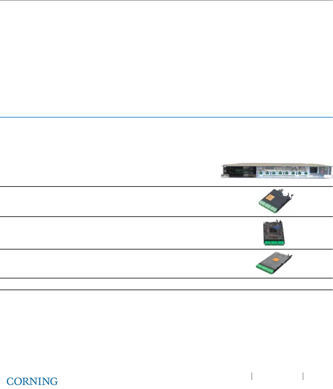
Appendix B: Specifications P/N 709C011801 Page 141
DRAFT
Optical Interface Unit (OIU)
(continued)
Physical
Characteristics
(Chassis +
Modules)
Mounting: Rack-mount – 19 in and 4U
Dimensions
( H x W x D):
Chassis: 7 x 17.3 x 18.95 in
(177.8 x 440 x 481.7 mm)
Cable Management
Tray:
6.96 x 20.02 x 4.35 in
(176.9 x 508.6 x 110.6 mm)
Weight: Chassis :
Per OIM:
Per OIX:
ACM:
PSM:
37 lbs (16.8 kg)
1.5 lbs (0.7 kg)
1.54 lbs (0.7 kg)
2.2 lbs (1.0 kg)
1.98 lbs (0.9 kg)
Intermediate Centralized Unit (ICU)
ICU will host the following modules:
1. PSM-I; Power Supply Module, up to four PSM-I modules can be installed.
2. Pretium EDGE® Module – MTP® to LC APC splice module/cassette/field-term cassette. Up to two EDGE® Modules can
be installed.
Chassis Interfaces
Power Input: 110-240 V AC, 50-60 Hz power
Output: Eight DC ports- 57 V DC, Max. 60V (UL limit)
Pretium Edge
®
Module
Interfaces
Pretium EDGE® Module, 12 F, LC APC to MTP®
APC Connector, Single-mode (OS2)
Pretium Edge
®
Splice
Cassette Interfaces
12 F, LC duplex, Single-mode APC, single-fiber
Pretium Edge
®
Field-Term
Cassette Interfaces
12 F, LC duplex, Single-mode APC, No Pigtail
Power Consumption
ICU with four PSM-I: 942 W
Physical Characteristics
(Chassis)
Mounting: Rack-mount – 19 in 1U
Dimensions
(H x W x D):
1.74 x 17 x 19.2 in
(44.4 x 431.8 x 11.96 mm)
Weight: 5.5 lbs (2.5 kg) – without PSM
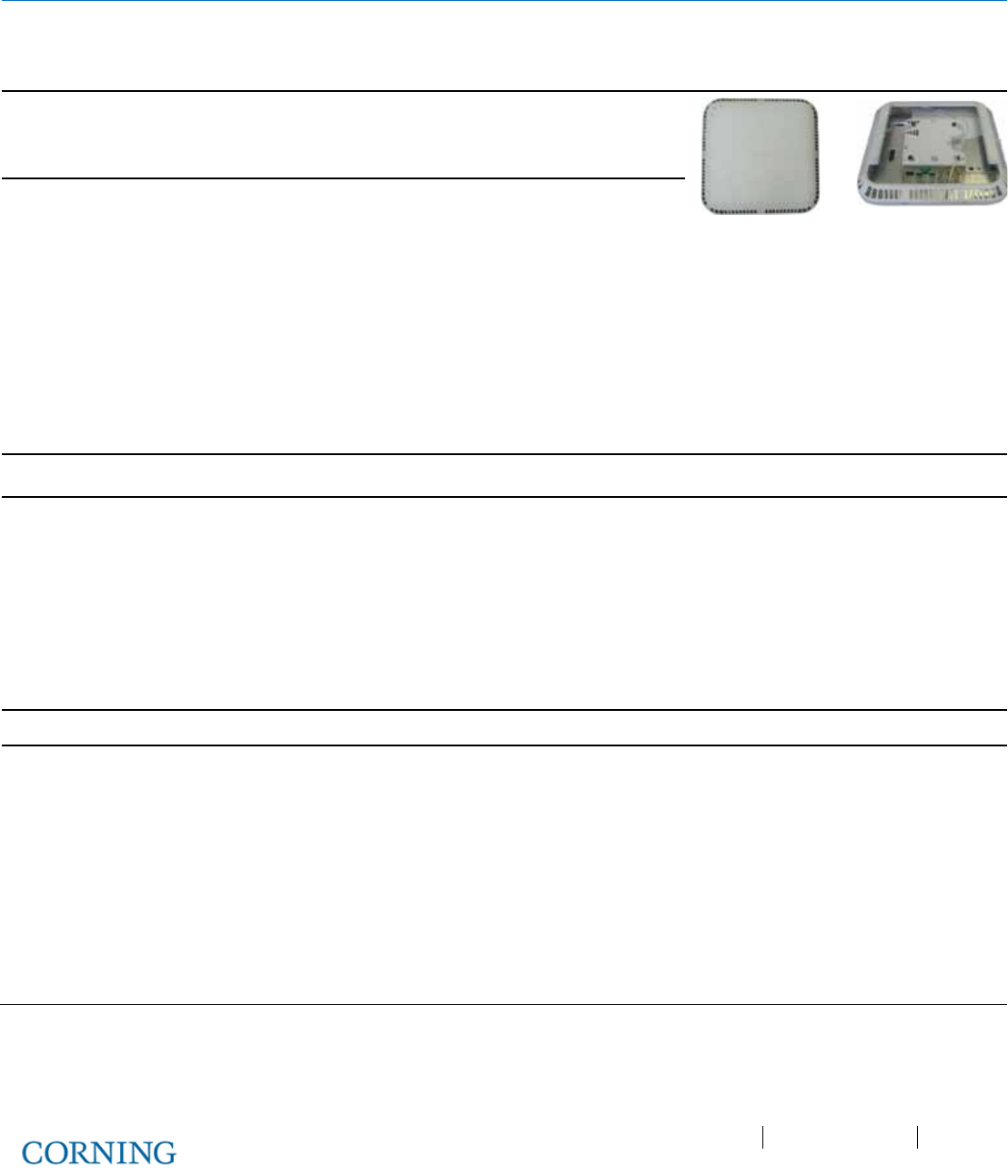
Appendix B: Specifications P/N 709C011801 Page 142
DRAFT
Remote Access Unit (RAU)
RAU will host the following modules:
1. RxU; Remote Expansion Module, for additional LTE and AWS MIMO service. One module per RAU.
2. GEM; Giga bit Ethernet Module – upgrade module for the RAU. One module per RAU
Supported Services
SISO: CELL, PCS, AWS, 700LTE
MIMO: AWS/ 700LTE
(with Expansion Module - RxU)
Interface Connections
Two LC APC SM fiber connectors; UL and DL
Two DC power Inputs ports; Main and secondary in case
of PoE clients.
Two QMA RF Ports; for External cavity filter (In/Out) use
- LTE and CELL filters
One Broadband External antenna QMA connector
(connected antenna must have a return loss of 12 dB)
One RJ-45 MGMT (local) connection
RxU module interface – power, digital and RF
GEM module Interface – power and digital
Antenna
Omni Directional; 0 dBi (15◦ down from horizon)
Power Consumption
For Main Power Input: Input Range: 37-57 V DC
RAU: 37 V; 35 W
RAU + RxU: 37 V; 60 W
RAU + GEM: 37 V; 39 W
RAU + RxU + GEM: 37 V; 64 W
For Secondary Power
Input:
For 2 PoE ports of 802.3af: 43 V; 30 W (Input range: 43 - 57 V DC)
For 2 PoE ports of 802.3at: 52 V; 62 W (Input range: 52 - 57 V DC)
Management
Managed via the HCM
Physical Characteristics
(Enclosure and Modules)
Mounting: Wall/ceiling (Horizontal mount)
Mounting bracket included in installation kit
Dimensions
(H x W X D):
4 x 13.1 x 13.1 in (including mounting bracket)
(101.6 x 332.7 x 332.7 mm)
Weight: RAU only: 7.93 lbs (3.6 kg)
RAU + RXU + GEM: 12.12 lbs (5.5 kg)
Environment
Ambient Temperature: Wall-mount installations: 45◦C (113◦F)
Ceiling-mount installations: 50◦C (122◦F)
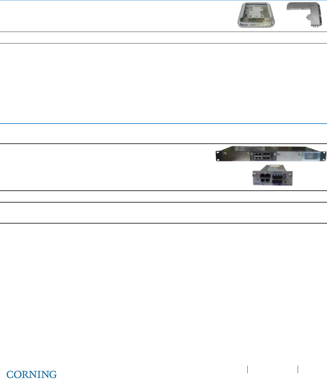
Appendix B: Specifications P/N 709C011801 Page 143
DRAFT
Remote Expansion Unit (RxU)
Services
Upgrade module supporting two services
AWS MIMO and LTE 700 MIMO
Interfaces
Three pins for integration with RAU (power, control and RF)
Management
Management via host RAU
Physical Characteristics
Mounting: Installed in the RAU enclosure
Dimensions
(H x W x D):
1.09 x 12.8 x 9.8 in
(27.7 x 327.5 x 250 mm)
Weight: 3.08 lbs (1.4 kg)
Digital Coverage Component Specifications
Centralized Ethernet Unit (CEU)
CEU will host the following module:
Three CEMs; Centralized Ethernet Module; media and rate converter, Ethernet (copper) to fiber.
Interfaces
CEM supports four 10/100/1000BASE-T RJ-45 connectors
to four LC UPC fiber connectors
Four 10/100/1000BASE-T Copper ports
Four 1000BASE-X fiber SFP
Throughput
Eight Gbps forwarding per CEM
Power
Input: 110-240 V AC, 50-60 Hz power
Power Consumption (fully occupied): 50 W
Physical
Characteristics
Mounting: Rack-mount 19 in; 1U
Dimensions
(H x W x D):
CEU: 1.71 x 17/19 (with mounting ears x 8.5 in
(43.66 x 431.8 / 482.8 with mounting ears x 216 mm)
CEM
Module:
1.41 x 3.94 x 7.68 in
(36 x 100.14 x 195.14 mm)
Weight: CEU: 7.55 lb (3.4 kg)
CEM
Module:
1.44 lb (0.65 kg)
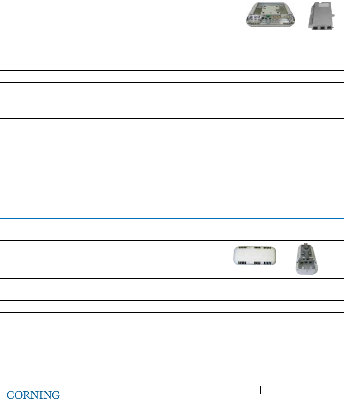
Appendix B: Specifications P/N 709C011801 Page 144
DRAFT
Gigabit Ethernet Module (GEM)
GEM – Ethernet over fiber to copper
10/100/1000BASE-T Ethernet 1000BASE-X fiber.
Two 802.3at compliant Power over Ethernet (PoE) PSE ports
Interfaces
GEM – L2 switch contains:
One 1000BASE-X fiber SFP
Two 10/100/1000BASE-T with 802.3at compliant Power over
Ethernet (PoE+) PSE ports
Throughput
Six Gbps forwarding rate
Power
Installations with RAU - powered via RAU Secondary power
input (see RAU power consumption spec)
Installations with GEU-S – powered via GEU power input (see
GEU-S power consumption spec)
Switching
IPv4 and IPv6 transparent
MAC table 512 entries
VLAN - unfiltered forwarding between ports
IGMP forward to all ports, no snooping
Physical
Characteristics
Mounting:
Standalone: GEU-S
Add-on: RAU Upgrade Module
Dimensions
(H x W x D):
1.28 x 3.79 x 5.95 in
(32.7 x 96.3 x 151.3 mm)
Weight: 1.1 lbs (0.5 kg)
Standalone Gigabit Ethernet Unit (GEU-S)
GEU-S will host the following module:
GEM; Gigabit Ethernet Module; Media converter, Ethernet over fiber to Copper.
Services
Supplies power and management port for hosted modules.
When it hosts a GEM it allows it to perform media
conversion services from Fiber to Copper and to supply
PoE + PSE services
Interfaces
DC PWR connector
Service Port – RJ-45 (to GEM)
Power Input
42-57 V DC
Physical
Characteristics
Mounting: Wall/ceiling mount
Dimensions
(H x W x D):
5.01 x 10.51 x 3.26 in (including mounting bracket)
(127.5 x 267 x 83 mm)
Weight: 2.64 lbs (1.2 kg)
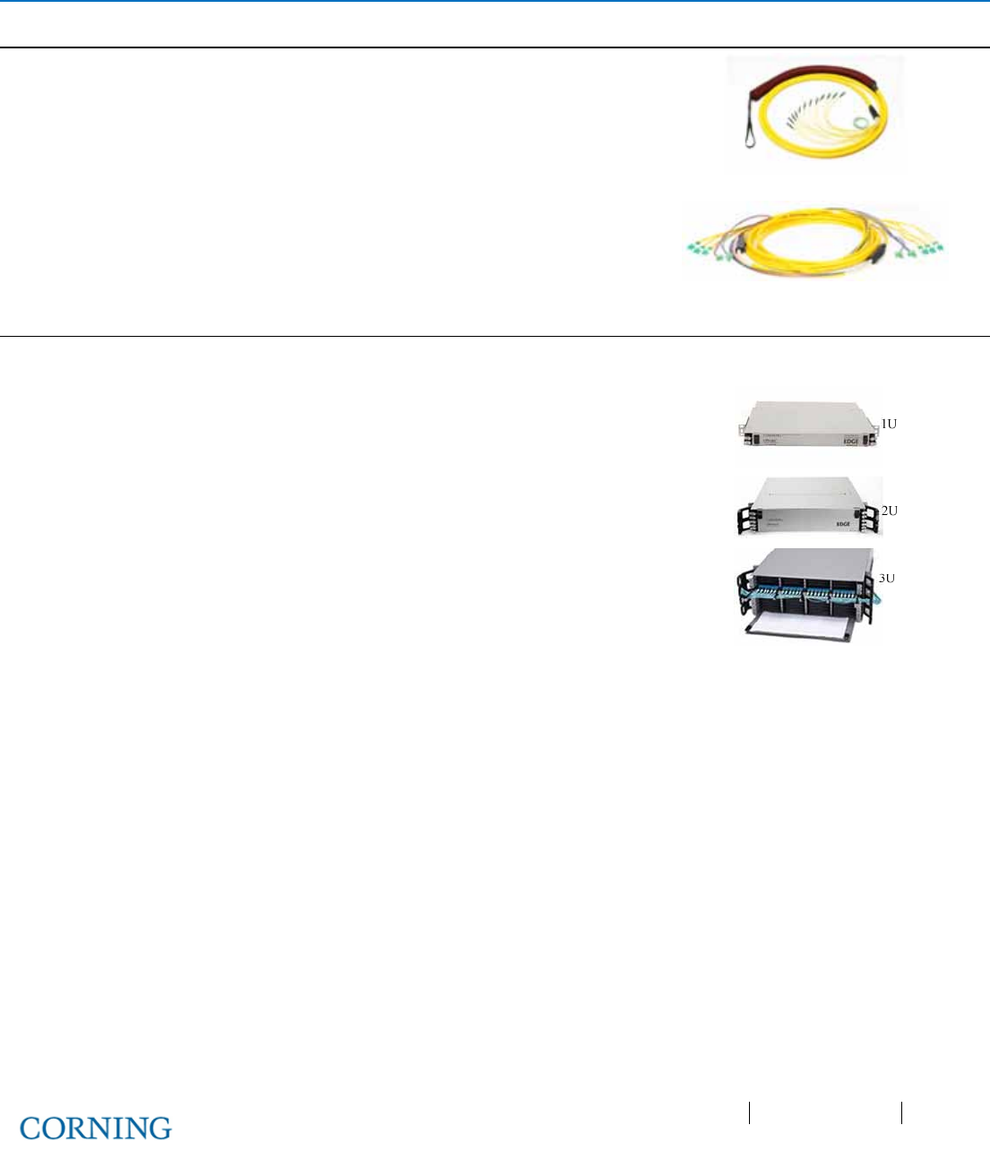
Appendix B: Specifications P/N 709C011801 Page 145
DRAFT
Optical: Cabling, Unit/Modules Specifications
Cabling
Vertical
Plug & Play™ Plenum Optical cables
MTP® Fiber Connectors
12 – 144 fibers
Two-sided or one-sided
Armored, non-armored
Horizontal
Composite Plenum tether assemblies
Fiber: LC APC, 2 – 24 fibers
Cu: 16AWG, 14AWG, 12AWG; 2 – 12
Conductors
Armored, non-armored
Fiber Management
FMU
1U: 144 Fibers
2U: 288 Fibers
4U: 576 Fibers
Plug & Play™ Modules or Splice Cassettes

Appendix B: Ordering Information P/N 709C011801 Page 146
DRAFT
Appendix B: Ordering Information
HEU and OIU Assemblies and Modules
Part Number
Description
HEU:
Headend Unit assembly (without RIMs); support for 1-12 RIMs:
HEU-2-00-1-A-H Hosts two RIX modules; one PSM-AC module and one HCM module
HEU-2-00-1-D-H Hosts two RIX modules; one PSM-DC module and one HCM module
HEU-2-00-1-A-A Hosts two RIX modules; one PSM-AC module and one ACM module
HEU-2-00-1-D-A Hosts two RIX modules; one PSM-DC module and one ACM module
HEU-1-00-1-A-H Hosts one RIX module; one ETM module; one PSM-AC and one HCM module
HEU-1-00-1-D-H Hosts one RIX module; one ETM module; one PSM-DC and one HCM module
HEU-1-00-1-A-A Hosts one RIX module; one ETM module; one PSM-AC and one ACM module
HEU-1-00-1-D-A Hosts one RIX module; one ETM module; one PSM-DC and one ACM module
HEU Modules:
HCM Head End Control Module; Includes two RJ-45 cables (2 m)
RIX Radio Interface Expander – HEU expansion module; two must be ordered
RIM: Radio Interface Module for HEU chassis
RIM-L70 LTE 700 MHz service
RIM-C85 CELL 850 service MHz service
RIM-P19 PCS 1900 MHz service
RIM-A17 AWS 1700 MHz service
RIM-L70-M LTE 700 MHz MIMO service
RIM-A17-M AWS 1700 MHz MIMO service
OIU
Optical Interface Unit assembly (without OIMs); support for 1-12 Optical Interface
Modules
OIU-2-00-1-A-A Hosts two OIX modules, one PSM-AC module and one ACM module
OIU-2-00-1-D-A Hosts two OIX modules, one PSM-DC module and one ACM module
OIU-1-00-1-A-A Hosts one OIX module; one ETM module; one PSM-AC and one ACM module
OIU-1-00-1-D-A Hosts one OIX module; one ETM module; one PSM-DC and one ACM module
OIU Modules:
OIM Optical Interface Module for OIU Chassis; three Optical links
Additional HEU and OIU Modules
ACM Auxiliary Control Module; Includes two RJ-45 cables (2 m)
PSM-AC AC Power Supply – installed in HEU and OIU chassis; includes US plug power cords
PSM-DC DC Power Supply - installed in HEU and OIU chassis; includes 48 V DC six pin
terminal block connector
ETM Expander Termination Module; 50 Ohm; used for terminating unoccupied RIX/OIX slot

Appendix B: Ordering Information P/N 709C011801 Page 147
DRAFT
Remote Units
Part Number
Description
RAU:
Remote Access Unit
RAU
RAU supporting CELL850, PCS1900, LTE700 MHz and AWS1700; SMF
RAU-ME RAU supporting (SISO) CELL850 and PCS1900; MIMO for LTE700 and AWS bands;
two PoE and Ethernet ports; support for Ethernet services; SMF
RAU-M
RAU supporting (SISO) CELL850 and PCS1900; MIMO for LTE700 and AWS bands;
SMF
RAU-E
RAU supporting CELL850, PCS1900, LTE700 MHz and AWS1700; two PoE and
Ethernet ports; support for Ethernet services; SMF
ICU:
Intermediate Centralized Unit; US power cord included
ICU-24-P-12-AF-H-4 24 fibers; hosts two splice cassette modules and four PSM-I modules
ICU-24-P-12-AF-H-3 24 fibers; hosts two splice cassette modules and three PSM-I modules
ICU-24-P-12-AF-H-2 24 fibers; hosts two splice cassette modules and two PSM-I modules
ICU-24-P-12-AF-H-1 24 fibers; hosts two splice cassette modules and one PSM-I module
ICU-12-P-12-AF-H-4 12 fibers; hosts one splice cassette module and four PSM-I modules
ICU-12-P-12-AF-H-3 12 fibers; hosts one splice cassette module and three PSM-I modules
ICU-12-P-12-AF-H-2 12 fibers; hosts one splice cassette module and two PSM-I modules
ICU-12-P-12-AF-H-1 12 fibers; hosts one splice cassette module and one PSM-I module
ICU-24-M-12-AF-0-4 24 fibers; hosts two EDGE® modules and four PSM-I modules
ICU-24-M-12-AF-0-3 24 fibers; hosts two EDGE® modules and three PSM-I modules
ICU-24-M-12-AF-0-2 24 fibers; hosts two EDGE® modules and two PSM-I modules
ICU-24-M-12-AF-0-1 24 fibers; hosts two EDGE® modules and one PSM-I module
ICU-12-M-12-AF-0-4 12 fibers; hosts one EDGE® module and four PSM-I modules
ICU-12-M-12-AF-0-3 12 fibers; hosts one EDGE® module and PSM-I modules
ICU-12-M-12-AF-0-2 12 fibers; hosts one EDGE® module and two PSM-I modules
ICU-12-M-12-AF-0-1 12 fibers; hosts one EDGE® module and one PSM-I module
PSM-I ICU Power Supply Module
Digital Path Units
Part Number Description
GEU-S Standalone Gigabit Ethernet Unit
CEU Centralized Ethernet Unit; hosts up to three CEM modules
CEM Centralized Ethernet Module; includes SFP and UPC to APC adapter

Appendix B: Ordering Information P/N 709C011801 Page 148
DRAFT
Accessories
Part Number
Description
ETM
Expander Termination Module; 50 Ohm; used for terminating unoccupied Expander
slots
CblTray
HEU/OIU Cable management tray and door sleeve; chassis sleeve for managing
cables and door for covering front panel
AK-RAU-BRCK-MM
Accessory kit used for mid-mount acoustic ceiling installations of the RAU; includes flat
bar and plate for assembling the RAU; assembly replaces standard acoustic tile (RAU
ordered separately)
37HP900162-006F MTP-LC APC Harness Cable; Connector for splitting fibers (six) leading from OIM to
(FMU) Edge module
ERFC:
Expander RF Cable; SMP to SMP connector
ERFC16 L= 16 in; 9 pin
ERFC24 L= 24 in; 9 pin
ERFC34 L= 34 in; 9 pin
ERFC40 L= 40 in; 9 pin
ERFC59 L= 59 in; 9 pin
PCKC:
Pilot Transport Cable; Single QMA to QMA
PCKC20 L=20 in
PCKC47 L=47 in
PCKC63 L=63 in
PCKC79 L=79 in
Hardware
Part Number
Description
EDGE-01U-SP 1U Rack-Mount Fiber Housing, holds 12 Pretium EDGE® modules or splice
cassettes
ECM-UM12-18-89 12-Fiber LC APC EDGE PnP Module
EDGE-CS12-AF-P00RE
Pretium EDGE
®
Splice Cassette
EDGE-CS12AF Pretium EDGE
®
Field-Term Cassette
CDF-RJ12-BKT
12-in Rack Bracket for managing cables
FMU: Fiber Management Unit; EDGE® -01U-SP housing; hosts EDGE® module
ED1-12M12AF-0R0000
12 Fibers
ED1-24M12AF-0R0000
24 Fibers
ED1-48M12AF-0R0000 48 Fibers
ED1-72M12AF-0R0000 72 fibers
ED1-96M12AF-0R0000
96 Fibers
ED1-E4M12AF-0R0000
144 Fibers
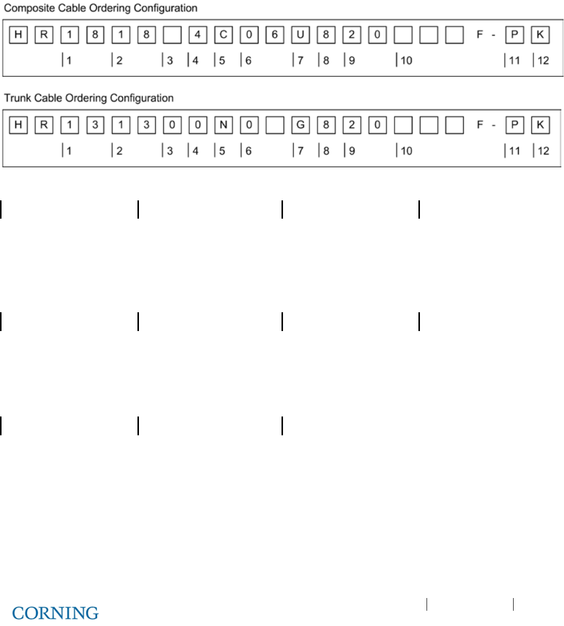
Appendix B: Ordering Information P/N 709C011801 Page 149
DRAFT
Cable Ordering Information
Cable Configurations
1
4
7
10
Connector.
Cu conductor count.
Fiber type.
Select cable length.
13 = MTP® Connector, SM
Elite
0 = 0 conductors U = ZBL Fiber
004 – 999 ft.
18 = LC/APC Duplex 4 = 4 conductors G = XB fiber
2
5
8
11
Connector. Cu connectors. Jacket type. Pulling grip type.
13 = MTP® Connector, SM
Elite
Cu = With connectors
8 = Plenum Indoor
P = One-sided pulling grip
18 = LC/APC Duplex
N = No connectors
3
6
9
12
Select cu wire gauge Fiber count. Armored/non-armored Kit type
0 = No Cu Wire 06 = 6 fibers 20 = Non-armored
K = 2 Strain relief trunk holders
F = 12AWG 24 = 24 fibers
G = 14AWG 48 = 48 fibers
H = 16AWG 72 = 72 fibers
K = 20AWG 96 = 96 fibers
E4 = 144 fibers

Appendix B: Ordering Information P/N 709C011801 Page 150
DRAFT
Corning MobileAccess Inc. • 13221 Woodland Park Rd, Suite 400 • Herndon, VA 20171 USA
866-436-9266 • FAX: 703-848-0280 • Tech Support Hotline: 410-553-2086 or 800-787-1266 • www.corning.com/mobileaccess
Corning MobileAccess reserves the right to improve, enhance and modify the features and specifications of Corning MobileAccess products without prior notification. ONE™ is a trademark of Corning Cable
System Brands, Inc. MTP is a registered trademark of USConec, Ltd. All other trademarks are the properties of their respective owners. Corning MobileAccess is I
SO 9001 certified. © 2013 Corning MobileAccess.
All rights reserved. Published in the USA. CMA17FEB1
UM_ONE_709C011801_20FEB14