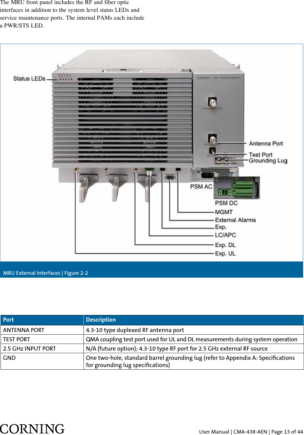
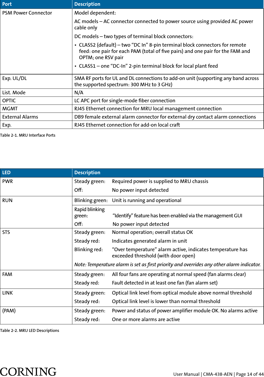
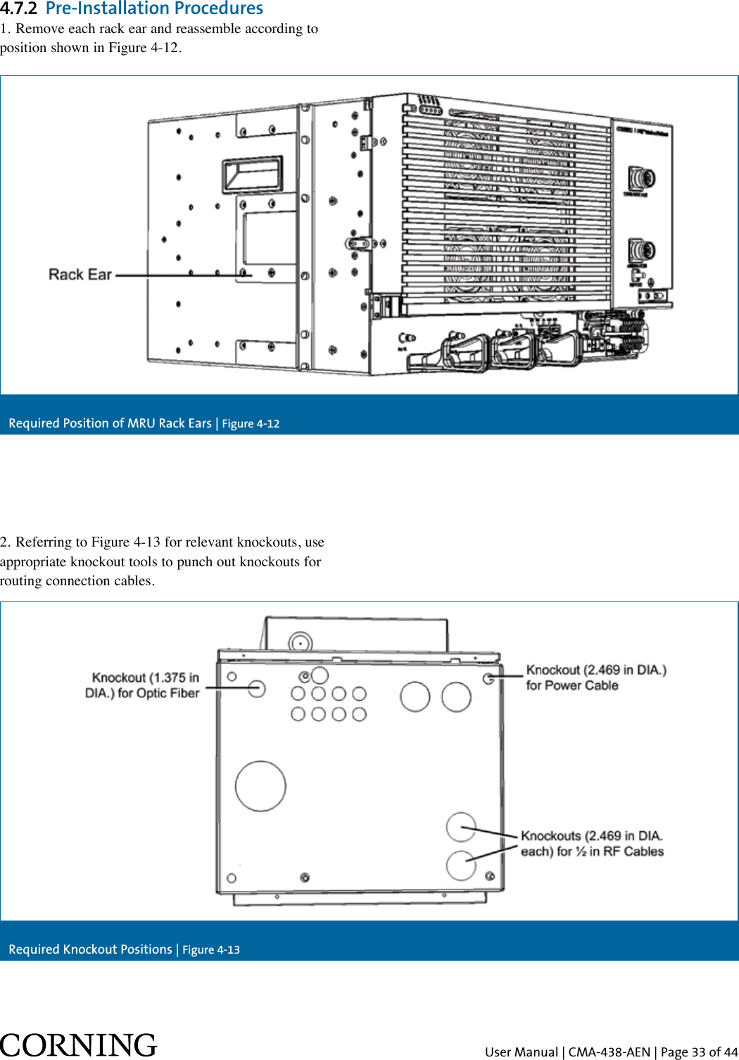
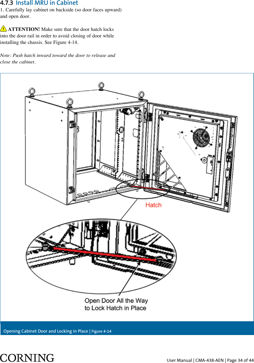
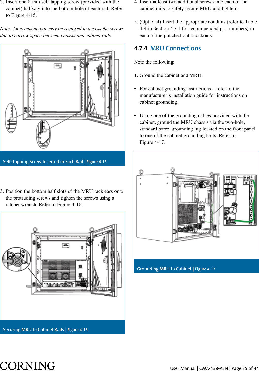
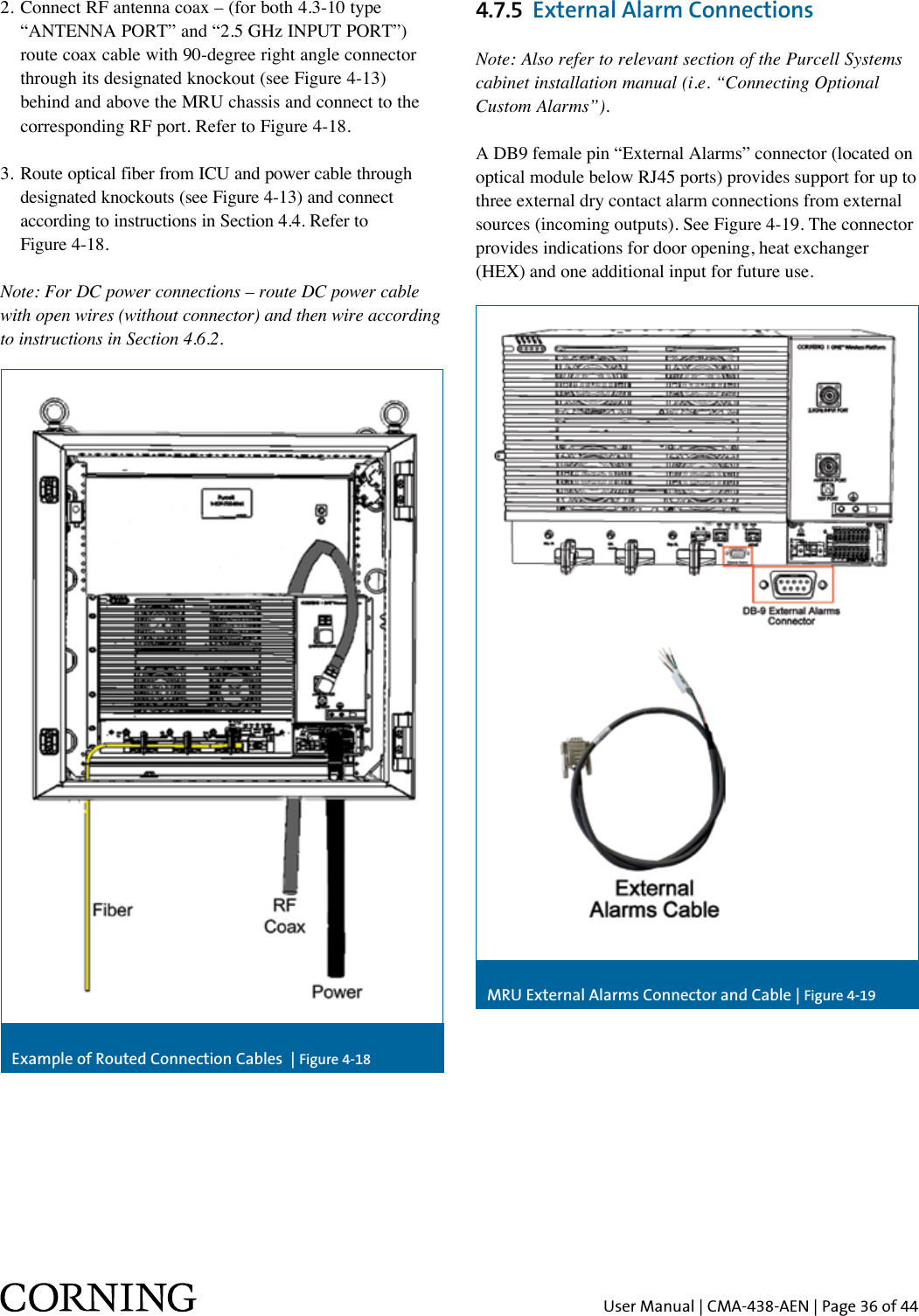
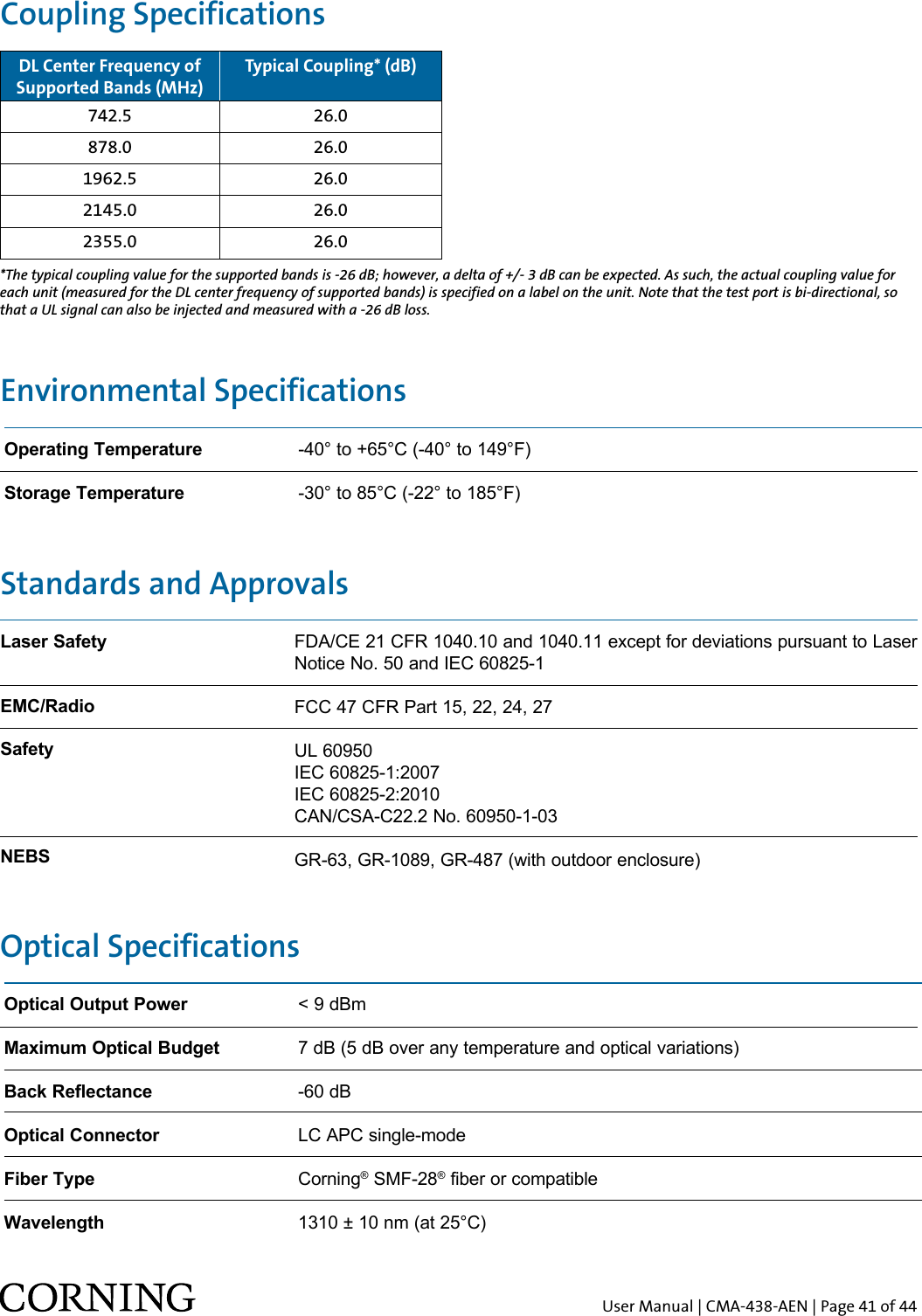
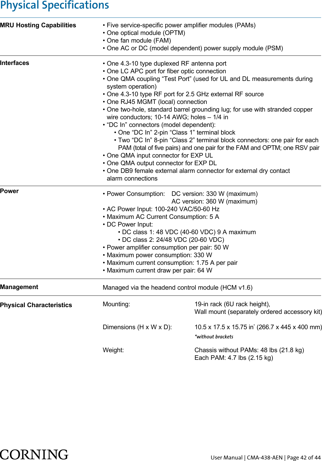
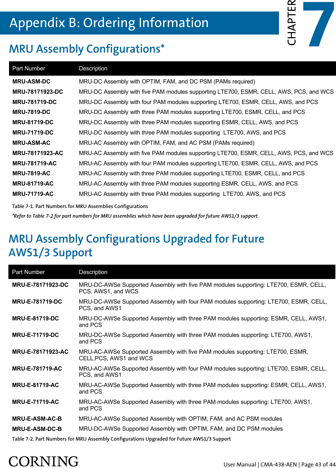
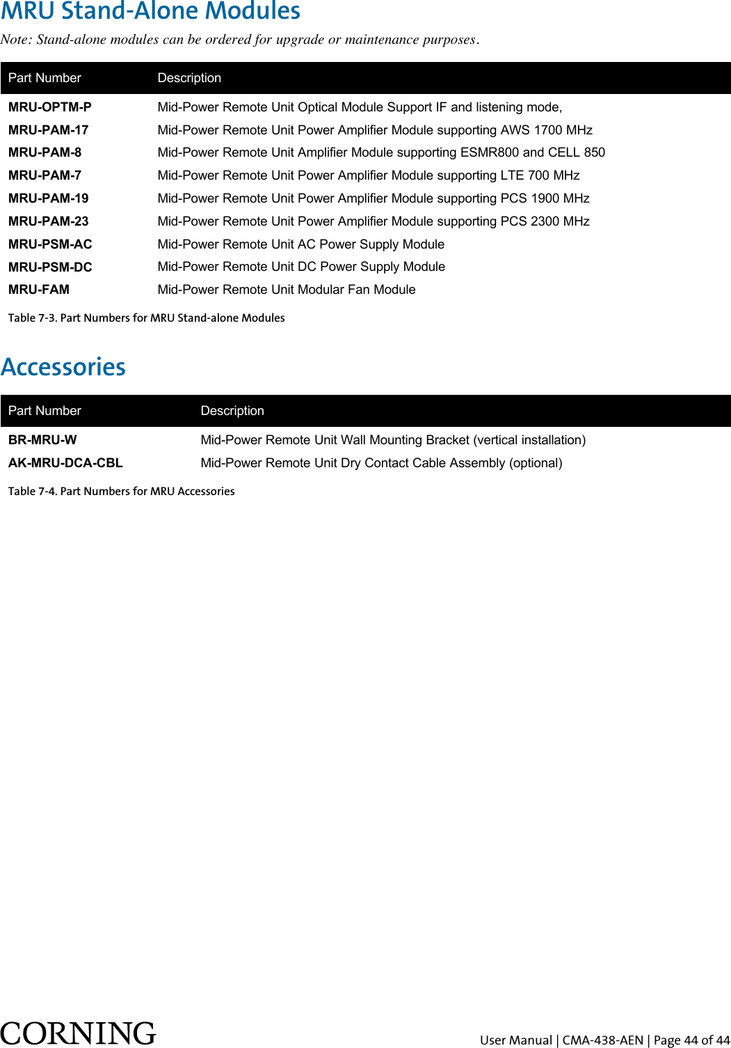
Corning Optical Communication Wireless 1MRU21-3 MRU-Mid Power Remote Unit with AWS-3 Support User Manual

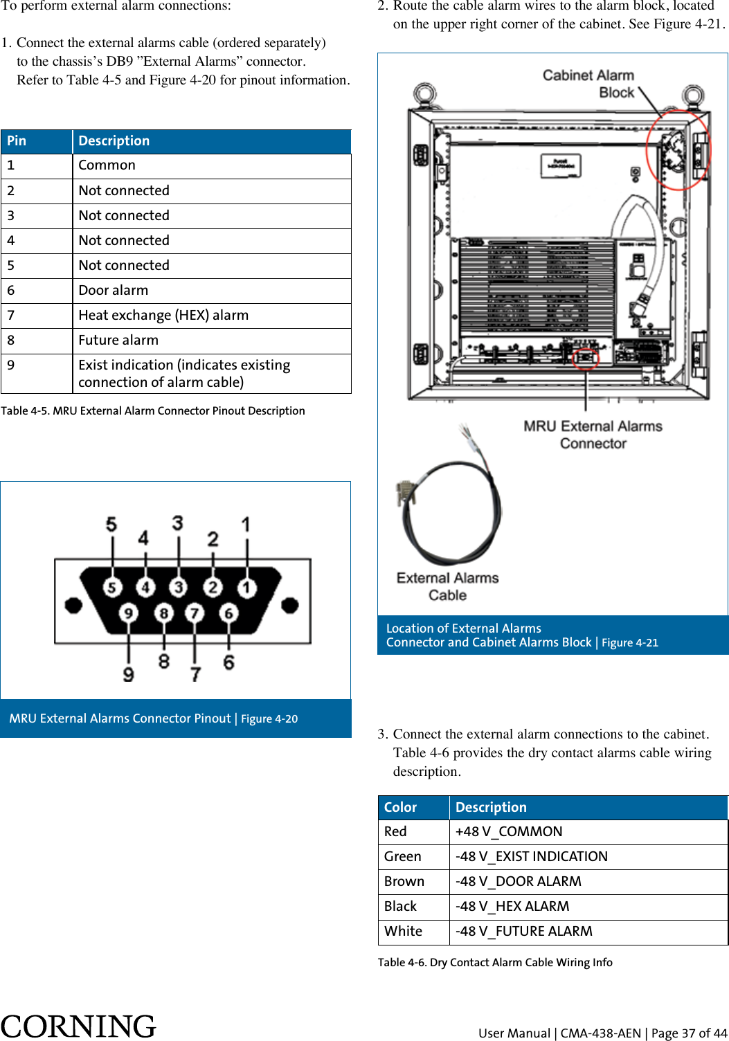
Corning Optical Communication Wireless MRU-Mid Power Remote Unit with AWS-3 Support Users Manual

Users Manual

Corning Mid-Power Remote Unit (MRU)User Manual
User Manual | CMA-438-AEN | Page 2 of 44WarrantiesHardware WarrantyCorning warrants to the original purchaser (“Customer”)  that for the duration of the warranty period, one (1) year,  commencing on the date of shipment of the Hardware, unless  otherwise agreed in writing by Corning (the “Hardware  Warranty Period”), the Hardware furnished by Corning  shall be free in all material respects from defects in material  and workmanship, and shall conform to the applicable portions  of the Specifications, as defined below (the “Hardware  Warranty”). If notified by Customer of any such defects  in material or workmanship or nonconformity with applicable  portions of the Specifications within the Hardware Warranty  Period, Corning shall promptly, at its own election and  expense, repair or replace any such Hardware proven to be  defective under the terms of this Hardware Warranty. Such  repair or replacement shall be Customer’s sole remedy and  Corning sole obligation in the event this Hardware Warranty  is invoked. If any components comprising a part of the  Hardware are replaced or repaired during the Hardware  Warranty Period, the Hardware Warranty Period for such  repaired or replaced components shall extend to the longer  of (i) the balance of the Hardware Warranty Period or (ii)  three (3) months from the date of repair or replacement. For  purposes of this Warranty, “Specifications” shall mean the  specifications and performance standards of the Products as  set forth in documents published by Corning and delivered to Customer which contain technical specifications or  performance standards for the Products.If Customer invokes this Hardware Warranty, it shall notify Corning promptly of the claimed defect. Customer will allow Corning to inspect the Hardware at Customer’s location, or to return the Hardware to Corning closest repair facility. For Hardware returned to Corning repair facility, Customer shall be responsible for payment of all transportation and freight costs (including insurance) to Corning’s repair facility, and Corning shall be responsible for all transportation and freight costs (including insurance) incurred in connection with the shipment of such Hardware to other repair facilities of Corning and/or its return to Customer.Notwithstanding the foregoing, in no event will Corning be liable for damage to Products resulting from improper handling during or after shipment, misuse, neglect, improper installation, operation or repair (other than by authorized Corning personnel), alteration, accident, or for any other cause not attributable to defects in materials or workmanship on the part of Corning. Corning shall not reimburse or make any allowance to Customer for any labor charges incurred by Customer for replacement or repair of any goods unless such charges are authorized in advance in writing by Corning. Software WarrantyCorning warrants to the original purchaser (“Customer”) that  for the duration of the warranty period, one (1) year,  commencing on the date of shipment of the Software, unless  otherwise agreed in writing by Corning (the “Software Warranty Period”), the Software shall conform with, and  perform the functions set forth in the Specifications, and  shall be free from defects in material or workmanship (the  “Software Warranty”). In the event the Software is proven  to be defective under the terms of this Software Warranty,  Corning shall correct such defects or failure and ensure that the Software conforms with, and performs the functions set forth in, the Specifications. Customer will allow Corning to inspect the Software at Customer’s location or to return it to Corning’s closest repair facility.Notwithstanding the foregoing, Corning shall have no obligation under the Software Warranty if the Software is modified or used with hardware or software not supplied or approved by Corning or if the Software is subject to abuse, improper installation or application, accident, electrical  or environmental over-stress, negligence in use, storage,  transportation, or handling Third-party software distributed  with the Software may carry certain warranties which, to the maximum extent allowed by law, Corning hereby assigns,  transfers and otherwise conveys to Customer, provided,  however, that Corning itself provides no warranty of any  kind, express, implied, statutory or otherwise, for any  third-party software provided hereunder.Corning does not warrant any hardware, software, or  services not provided by Corning.THIS WARRANTY IS THE ONLY WARRANTY MADE BY CORNING AND IS IN LIEU OF ALL OTHER WARRANTIES, EXPRESS OR IMPLIED INCLUDING, BUT NOT LIMITED TO, THE IMPLIED WARRANTIES OF MERCHANTABILITY AND FITNESS FOR A PARTICULAR PURPOSE. CORNING SHALL NOT BE LIABLE FOR ANY OTHER DAMAGE INCLUDING, BUT NOT LIMITED TO, INDIRECT, SPECIAL OR CONSEQUENTIAL DAMAGES ARISING OUT OF ORIN CONNECTION WITH FURNISHING OF GOODS, PARTS AND SERVICE HEREUNDER, OR THE PERFORMANCE, USE OF, OR INABILITY TO USE THE GOODS, PARTS, AND SERVICE. CORNING SALES AGENTS OR REPRESENTATIVES ARE NOT AUTHORIZED TO MAKE COMMITMENTS ON WARRANTY RETURNS.
User Manual | CMA-438-AEN | Page 3 of 44ReturnsIn the event that it is necessary to return any product against above warranty, the following procedure shall be followed:1. Return authorization is to be received from Corning    prior to returning any unit. Advise Corning of the   model, serial number, and discrepancy. The unit may    then be forwarded to Corning, transportation prepaid.    Devices returned collect or without authorization may    not be accepted.2. Prior to repair, Corning will advise the customer of    our test results and any charges for repairing customer-   caused problems or out-of-warranty conditions etc.3. Repaired products are warranted for the balance of the    original warranty period, or at least 90 days from date    of shipment.Limitations of LiabilitiesCorning’s liability on any claim, of any kind, including negligence for any loss or damage arising from, connected with, or resulting from the purchase order, contract, quotation, or from the performance or breach thereof, or from the design, manufacture, sale, delivery, installation, inspection, operation or use of any equipment covered by or furnished under this contact, shall in no case exceed the purchase price of the device which gives rise to the claim.Except as expressly provided herein, Corning makes no warranty, expressed or implied, with respect to any goods, parts, and services provided in connection with this agreement including, but not limited to, the implied warranties of merchantability and fitness for a particular purpose. Corning shall not be liable for any other damage including, but not limited to, indirect, special or consequential damages arising out of or in connection with furnishing of goods, parts and service hereunder, or the performance, use of, or inability to use the goods, parts,  and service.Note: The grantee is not responsible for any changes or modifications not expressly approved by the party responsible for compliance. Such modifications could  void the user's authority to operate the equipment.Reporting DefectsThe units were inspected before shipment and found to be free of mechanical and electrical defects. Examine the units for any damage that may have been caused in transit. If damage is discovered, file a claim with the freight carrier immediately. Notify Corning as soon as possible in writing.Note: Keep all packing material until you have completed the inspection.Warnings and AdmonishmentsThere may be situations, particularly for workplace environments near high-powered RF sources, where recommended limits for safe exposure of human beings to RF energy could be exceeded. In such cases, restrictive measures or actions may be necessary to ensure the safe use of RF energy. The equipment has been designed and constructed to prevent, as far as reasonably, practicable danger. Any work activity on or near equipment involving installation, operation or maintenance must be, as far as reasonably, free from danger.Where there is a risk of damage to electrical systems involving adverse weather, extreme temperatures, wet, corrosive or dirty conditions, flammable or explosive atmospheres, the system must be suitably installed to prevent danger. Equipment provided for the purpose of protecting individuals from electrical risk must be suitable for the purpose and properly maintained and used. This covers a range of activities including lifting, lowering, pushing, pulling, carrying, moving, holding, or restraining an object, animal, or person from the equipment. It also covers activities that require the use of force or effort, such as pulling a lever or operating power tools.Where some of the above mentioned activities are required, the equipment must be handled with care to avoid being damaged. Observe standard precautions for handling ESD-sensitive devices. Assume that all solid-state electronic devices are ESD sensitive. Ensure the use of a grounded wrist strap or equivalent while working with ESD-sensitive devices. Transport, store, and handle ESD-sensitive devices in static-safe environments.Regulatory Compliance Information WARNINGS!•   This  is  NOT a CONSUMER device. It is designed for installation by FCC LICENCEES and QUALIFIED INSTALLERS. You MUST have an FCC LICENSE or express consent of an FCC license to operate this device. Unauthorized use may result in significant forfeiture penalties, including penalties in excess of $100,000 for each continuing violation.
User Manual | CMA-438-AEN | Page 4 of 44RF SafetyTo comply with FCC RF exposure compliance requirements:  ATTENTION!Compliance with RF safety requirements:•   Corning products have no inherent significant RF radiation.•   The RF level on the downlink is very low at the downlink ports. Therefore, there is no dangerous RF radiation when the antenna is not connected.CAUTION!Use of controls, adjustments, or performance of procedures other than those specified herein may result in hazardous radiation exposure.Warning! Antennas used for this product must be fixed mounted on indoor permanent structures, providing a separation distance of at least 100 cm from all persons during normal operation.Warning! Each individual antenna used for this transmitter must be installed to provide a minimum separation distance of 100 cm or more from all persons and must not be co-located with any other antenna for meeting RF exposure requirements.Warning! Antenna gain should not exceed 12.5 dBi.Warning! The design of the antenna installation needs to be implemented in such a way so as to ensure RF radiation safety levels and non-environmental pollution during operation.About This ManualThis user guide provides all the information necessary to understand the architecture and general installation procedures and requirements of the Corning optical network evolution (ONE) solutuions mid-power remote unit (MRU). Note: The commissioning procedure, monitoring and  management capabilities, and configuration options of Corning optical network evolution (ONE) solutions elements are described in the Corning optical network evolution (ONE) solutions HCM and Web management user manual.Laser Safety•   Fiber optic ports of the Corning optical network evolution (ONE™) solutions emit invisible laser radiation at the 1310/1550 nm wavelength window.•   External optical power is less than 10 mW, internal optical power is less than 500 mW.•   To avoid eye injury never look directly into the optical ports, patch cords, or optical cables. Do not stare into beam or view directly with optical instruments. Always assume that optical outputs are on.•  ANTENNAS: Use only authorized and approved antennas, cables, and/or coupling devices! The use of unapproved antennas, cables, or coupling devices could cause damage and may be of violation of FCC regulations. The use of unapproved antennas, cables, and/or coupling devices is illegal under FCC regulations and may subject the user to fines. See Section 3.6 of this document.•   Only technicians familiar with fiber optic safety practices and procedures should perform optical fiber connections and disconnections of Corning optical network evolution (ONE) solutions devices and the associated cables.•   Corning optical network evolution (ONE) solutions MRU has been tested and certified as a Class 1 laser product to IEC/EN 60825-1 (2007). It also meets the requirements for a Hazard Level 1 laser product to IEC/EN 60825-2:2004 to the same degree.•   Corning optical network evolution (ONE) solutions MRU complies with 21 CFR 1040.10 and 1040.11 except for deviations pursuant to Laser Notice No. 50 (2007).Care of Fiber Optic Connectors•   Do not remove the protective covers on the fiber optic connectors until a connection is ready to be made.  Do not leave connectors uncovered when not connected.•   The tip of the fiber optic connector should not come  into contact with any object or dust.Company CertificationISO 9001:2000 and ISO 13485:2003Licensee Contact InformationIndustrial boosters may only be used by FCC licensees or those given express (individualized) consent of license. Corning Optical Communications Wireless certifies all of the VARs listed as licensed installers for Corning. For the list of licensed VARs, please contact the Tech Support Hotline: 410-553-2086 or 800-787-1266.
User Manual | CMA-438-AEN | Page 5 of 44Table of Contents1CHAPTER1.1 Key Features and Capabilities . . . . . . . . . . . . . . . .81.2 General System Specifications and Requirements. . .9  1.2.1  Environmental and Regulatory        Specifications  . . . . . . . . . . . . . . . . . . . . .9  1.2.2 Safety and Regulatory Approvals. . . . . . . . .9    1.2.3 Power Specifications . . . . . . . . . . . . . . . . .9  1.3 System Architecture  . . . . . . . . . . . . . . . . . . . . 10 1.4 System Monitoring and Management. . . . . . . . . 11 Introduction2  MRU Interfaces  . . . . . . . . . . . . . . . . . . . . . . . . 12  2CHAPTERMRU Interfaces3CHAPTERInstallation Guidelines3.1 Site Considerations. . . . . . . . . . . . . . . . . . . . . 15 3.2 Safety Guidelines  . . . . . . . . . . . . . . . . . . . . . .15 3.3 Installation Requirements  . . . . . . . . . . . . . . . .15  3.3.1  Rack Safety Instructions. . . . . . . . . . . . . 16   3.3.2  Rack Installation Guidelines  . . . . . . . . . .16 3.4 Power Requirements  . . . . . . . . . . . . . . . . . . . 16   3.4.1  Power Safety Instructions  . . . . . . . . . . . 16  3.4.2  Types of Power Supplies  . . . . . . . . . . . . 16  3.4.3  Circuit Breakers  . . . . . . . . . . . . . . . . . .16  3.4.4  Cable Routing  . . . . . . . . . . . . . . . . . . . 16 3.5 RF Coaxial Cable Guidelines . . . . . . . . . . . . . . .  17   3.5.1  General RF Cable Installation Procedures. . 17  3.5.2  RF Rules . . . . . . . . . . . . . . . . . . . . . . .17  3.5.3  Coax Cable Lengths and Losses . . . . . . . .17 3.6 Antenna Specifications and Guidelines  . . . . . . . .18 3.6.1 Authorized Antennas and Required         Specifications . . . . . . . . . . . . . . . . . . . . . 18 3.6.2 General Installation Guidelines  . . . . . . . . . 18 3.7 Fiber Optic Requirements . . . . . . . . . . . . . . . . . 18  3.7.1 Authorized Optical Cables . . . . . . . . . . . . . 18  3.7.2 Fiber Optic Rules . . . . . . . . . . . . . . . . . . . 18 3.8 Grounding Requirement  . . . . . . . . . . . . . . . . . 19 3.9 Manual Handling  . . . . . . . . . . . . . . . . . . . . . .19
User Manual | CMA-438-AEN | Page 6 of 446CHAPTERSupported Services  . . . . . . . . . . . . . . . . . . . . . . . . 40RF Parameters per Service. . . . . . . . . . . . . . . . . . . .40Coupling Specifications  . . . . . . . . . . . . . . . . . . . . . 41              Environmental Specifications  . . . . . . . . . . . . . . . . . 41  Standards and Approvals  . . . . . . . . . . . . . . . . . . . .41Optical Specifications . . . . . . . . . . . . . . . . . . . . . .41Physical Specifications  . . . . . . . . . . . . . . . . . . . . . 42Appendix A:  SpecificationsMRU Assembly Configurations  . . . . . . . . . . . . . . . . 43  MRU Assembly Configurations Upgrade for   Future AWS1/3 Support  . . . . . . . . . . . . . . . . . . . .43MRU Stand-Alone Modules . . . . . . . . . . . . . . . . . . . 44Accessories  . . . . . . . . . . . . . . . . . . . . . . . . . . . . . 44Cable Assemblies . . . . . . . . . . . . . . . . . . . . . . . . . 455.1 Extracting/Replacing PAM and OPTM . . . . . . . . . 39  7CHAPTER5CHAPTERAppendix B:  Ordering InformationMaintenanceTable of Contents (continued)4.1 Unpacking and Inspection . . . . . . . . . . . . . . . . .204.2 Mounting the MRU   . . . . . . . . . . . . . . . . . . . . .21     4.2.1   Rack Installation  .  .  .  .  .  .  .  .  .  .  .  .  .  .  .  .  .  21   4.2.2   Wall-Mount Installation. . . . . . . . . . . . . 22                  4.2.2.1  Unpacking and Inspection  . . . . . . . . 22                  4.2.2.2  Mounting MRU on Wall . . . . . . . . . . 23  4.3 Grounding MRU Chassis. . . . . . . . . . . . . . . . . . 25  4.4 Fiber Connections   . . . . . . . . . . . . . . . . . . . . . 26  4.5 RF Antenna Connections  . . . . . . . . . . . . . . . . . 27  4.6 Power Connections . . . . . . . . . . . . . . . . . . . . .28    4.6.1   AC Models  .  .  .  .  .  .  .  .  .  .  .  .  .  .  .  .  .  .  .  .  . 28    4.6.2   DC Models  . . . . . . . . . . . . . . . . . . . . .28                   4.6.2.1  CLASS2 Connector (remote feed). . . . 28                  4.6.2.2  CLASS1 Connector (local plant feed). . 30  4.7 Outdoor Installation  .  .  .  .  .  .  .  .  .  .  .  .  .  .  .  .  .  .  .  . 31    4.7.1   Items Required for Outdoor Installation . . 31    4.7.2   Pre-Installation Procedures  . . . . . . . . . . 33    4.7.3   Install MRU in Cabinet  . . . . . . . . . . . . . 34    4.7.4   MRU Connections  . . . . . . . . . . . . . . . . 35    4.7.5   External Alarm Connections. . . . . . . . . . 36  4.8 Verifying Normal Operation  . . . . . . . . . . . . . . .38  4CHAPTERInstallation
User Manual | CMA-438-AEN | Page 7 of 44Introduction 1CHAPTERThe MRU is a mid-power (2 W) remote solution for the Corning optical network evolution (ONE™) solutions.  The MRU provides remote indoor and outdoor coverage.  It is a fiber-fed, compact, and scalable multiservice  solution designed to complement the Corning optical network evolution (ONE) solutions by providing complete RF open space coverage for large-scale public venues such  as campus applications.The MRU consists of a compact enclosure that houses the RF modules, power elements, and the required interfaces, supporting up to seven bands in various combinations.  It enables multiple wireless technologies and operator services to be distributed over a single broadband infrastructure. The MRU can be deployed in new sites or alongside existing lower-power RAU/RAU5 remotes, sharing a common headend and element management system. Alongside Corning optical network evolution (ONE) solutions deployments, the MRU provides a comprehensive indoor and outdoor coverage solution for varying site requirements, supporting everything from high-rise buildings and campus topologies to stadiums and airports.Management and configuration options are provided for each MRU service via a Web session to the headend control module (HCM v1.6 and higher). The HCM enables centralized, single-source local and remote management of all system elements.
User Manual | CMA-438-AEN | Page 8 of 44Mid-Power Remote Unit (MRU) | Figure 1-11.1  Key Features and Capabilities•   Multi-frequency/multiservice  platform – supports LTE 700, ESMR, CELL, PCS, AWS, and WCS (including an integrated 2.5 GHz add-on port), accommodating GSM, CDMA, UMTS, LTE, and more.•  Multioperator-optimized platform – services from a number of operators can be distributed by the same unit.•  Cost-effective higher power – optimizes and reduces the number of antennas required to cover open areas by offering up to 33 dBm (2 W) composite power per frequency band.•  Operator-grade performance – advanced signal handling, RF filtering, and management ensures  operator-grade performance.•  Optical fiber savings – all services routed to an MRU are routed over a single optical fiber pair.•  Design and deployment flexibility – MRU available in AC or DC power supply options. Antenna splitting schemes are possible due to the higher power output capability.•  Modular and scalable design – modular design enables adding new wireless services easily and cost-effectively without disruption to workspaces or existing services. Supports external 2.5 GHz RF source.•  Simple installation and maintenance – all connections and status LEDs located on the front panel. MRU is modular, hot swappable, and field upgradable.•  Management and control – alarm forward to NOC or standard element management system (EMS) via SNMP, software controlled output power, and optical link auto gain control.
User Manual | CMA-438-AEN | Page 9 of 441.2  General System  Specifications and Requirements1.2.1  Environmental and Regulatory Specifications1.2.2  Safety and Regulatory Approvals1.2.3  Power SpecificationsOperating StorageTemperature -40° to +65°C (-40° to 149°F) -30° to 85°C (-22° to 185°F)Regulation/Standard  CategoryApprovalLaser Safety FDA/CE 21 CFR 1040.10 and 1040.11 except for deviations pursuant to Laser Notice No. 50 and IEC 60825-1EMC FCC 47 CFR Part 15, 22, 24, 27Safety UL 60950IEC 60825-1:2007IEC 60825-2:2010CAN/CSA-C22.2 No. 60950-1-03NEBS GR-63, GR-1089 (with outdoor enclosure)Power Specication DescriptionPower Consumption (maximum) 360 W (for fully loaded chassis)AC Power InputMaximum AC Current ConsumptionDC Power Input100-240 VAC/50-60 Hz5 ADC class 1: 48 VDC (40-60 VDC), 9 A maximumDC class 2: 24/48 VDC (20-60 VDC)Power amplier consumption per pair: 50 WMaximum power consumption: 330 W Maximum current consumption: 1.75 A per pairMaximum current draw per pair: 64 WTable 1-1. Temperature and Humidity SpecificationsTable 1-2. Safety and Regulatory ApprovalsTable 1-3. MRU Power Specifications
User Manual | CMA-438-AEN | Page 10 of 44System Architecture | Figure 1-21.3  System ArchitectureFigure 1-2 illustrates the MRU system architecture. In the downlink, at the headend, BTS/BDA RF signals are conditioned by service-specific RIMs installed in the headend unit (i.e. HEU/IHU), ensuring a constant RF level.  The conditioned signals are then forwarded to the OIU and converted by the OIMs to an optical signal for transporting over single-mode fiber to the MRUs at the remote locations. All mobile services are combined and distributed through a single antenna port over the broadband antenna infrastructure installed at the remote locations. In the uplink, the process is reversed. As illustrated in the system architecture shown in Figure 1-2, all mobile services are combined and distributed through a single antenna port over the broadband antenna infrastructure installed at the remote locations.
User Manual | CMA-438-AEN | Page 11 of 44Example of MRU Management GUI (SW v1.6) | Figure 1-31.4  System Monitoring  and ManagementThe MRU is centrally managed via the headend control module software management application (v1.6 and higher). Figure 1-3 shows the management tabs of the selected MRU. Refer to the “Headend Control Module (HCM) and Web Management GUI v1.6” user manual (CMA-423-AEN) for information on how to configure and manage the MRU.
User Manual | CMA-438-AEN | Page 12 of 44MRU Interfaces 2CHAPTERThis chapter provides detailed descriptions of the MRU chassis and main modules and interfaces. This content includes port and LED interface descriptions. The MRU comprises the following main modules: •   Power amplifier modules (PAM) – internal service-specific power amplifier module that interfaces to an optical interface module (OIM) at the headend site via a single-mode pair and supports one service. MRU supports up to seven bands. The PAM provides the additional amplification on the DL signals routed from the OIM toward the multiplexer. PAMs are pre-installed in designated slots according to supported band.•   Multiplexer – combines the UL and DL RF signals of the supported services in addition to external RF signal (future option for connecting to external 2.5 GHz signal source) while providing the proper filtering into a single duplexed antenna port.•   Optical Module – includes the fiber optic, RF expansion, and external alarm interfaces.•   Power supply module (PSM) – local AC or remote DC power feed (model dependent).•   Fan module (FAM) – integrated fan module comprised of four fans which are also monitored via the Web GUI. The MRU includes front panel interfaces (e.g. antenna, fiber optic connections, and LED status indicators) as well as status indicators per each internal module (which are accessed by opening the cabinet door). The following sections provide details on the front panel and internal module interfaces.MRU Main Modules | Figure 2-1
User Manual | CMA-438-AEN | Page 13 of 44The MRU front panel includes the RF and fiber optic interfaces in addition to the system level status LEDs and service maintenance ports. The internal PAMs each include a PWR/STS LED.MRU External Interfaces | Figure 2-2Port DescriptionANTENNA PORT 4.3-10 type duplexed RF antenna portTEST PORT QMA coupling test port used for UL and DL measurements during system operation 2.5 GHz INPUT PORT N/A (future option); 4.3-10 type RF port for 2.5 GHz external RF sourceGND One two-hole, standard barrel grounding lug (refer to Appendix A: Specications for grounding lug specications)
User Manual | CMA-438-AEN | Page 14 of 44Port DescriptionPSM Power Connector Model dependent:AC models – AC connector connected to power source using provided AC power cable onlyDC models – two types of terminal block connectors:•   CLASS2 (default) – two “DC In” 8-pin terminal block connectors for remote  feed: one pair for each PAM (total of ve pairs) and one pair for the FAM and OPTM; one RSV pair•  CLASS1 – one “DC-In” 2-pin terminal block for local plant feedExp. UL/DL SMA RF ports for UL and DL connections to add-on unit (supporting any band across the supported spectrum: 300 MHz to 3 GHz)List. Mode N/AOPTIC LC APC port for single-mode ber connection MGMT RJ45 Ethernet connection for MRU local management connection External Alarms DB9 female external alarm connector for external dry contact alarm connectionsExp.  RJ45 Ethernet connection for add-on local craft LED DescriptionPWR Steady green:   Required power is supplied to MRU chassis Off:  No power input detectedRUN Blinking green:  Unit is running and operationalRapid blinking  green:  “Identify” feature has been enabled via the management GUIOff:  No power input detectedSTS Steady green:  Normal operation; overall status OKSteady red:  Indicates generated alarm in unitBlinking red:   “Over temperature” alarm active, indicates temperature has  exceeded threshold (with door open)Note: Temperature alarm is set as rst priority and overrides any other alarm indicator.FAM Steady green:   All four fans are operating at normal speed (fan alarms clear)Steady red:   Fault detected in at least one fan (fan alarm set)LINK Steady green:   Optical link level from optical module above normal thresholdSteady red:  Optical link level is lower than normal threshold(PAM) Steady green:  Power and status of power amplier module OK. No alarms activeSteady red:  One or more alarms are activeTable 2-1. MRU Interface PortsTable 2-2. MRU LED Descriptions
User Manual | CMA-438-AEN | Page 15 of 44Installation GuidelinesThis chapter provides installation guidelines for the  Corning optical network evolution (ONE™) solutions MRU. The following installation rules are based on the assumption that the site survey and installation planning (including power requirements) have been completed. This preparation includes planning the distribution of antennas to provide the required coverage, as well as planning the layout of the devices and cables in the telecom closet or shaft.3.1  Site Considerations•   The distance between the MRU service antenna and the coverage area should correspond to line of sight (LoS) requirements for maximum coverage area. •  The maximum fiber path loss is 5 dB.•   The system delay of the optical system must be taken into consideration when there are neighboring BTS sites overlapping in coverage.3.2  Safety GuidelinesBefore installing the equipment, review the following safety information: •  Follow all local safety regulations when installing the   equipment.•  Only qualified personnel are authorized to install and   maintain the repeater.•  Ground specified equipment with the provided    grounding bolt.•  Do not use the grounding bolt to connect external devices.•  Follow electrostatic discharge (ESD) precautions.•  Use low-loss cables to connect the antennas. 3.3  Installation Requirements•  Mounting surface shall be capable of supporting the    weight of the equipment. •   In order to avoid electromagnetic interference, a proper mounting location must be selected to minimize interference from electromagnetic sources such as large electrical equipment.•  Working space available for installation and maintenance    for each mounting arrangement. •  Ensure unrestricted airflow. •  Ensure grounding connector is within reach of the    ground wire. •  Ensure a power source is within reach of the power cord    and the power source has sufficient capacity. •  Where appropriate, ensure unused RF connectors are   terminated. •  Do not locate the equipment near large transformers or    motors that may cause electromagnetic interference. •  Reduce signal loss in feeder cable by minimizing the    length and number of RF connections. •   Ensure the equipment is operated within the stated environment (refer to Appendix A: Specifications or  unit datasheet). •  Where appropriate, confirm availability of suitably    terminated grade of RF and optical fiber. •  Observe handling of all cables to prevent damage.3CHAPTER
User Manual | CMA-438-AEN | Page 16 of 443.3.1  Rack Safety InstructionsThe following guidelines are relevant to the rack installed units. Review the following guidelines to help ensure your safety and protect the equipment from damage during the installation.•  Only trained and qualified personnel should be allowed    to install or replace this equipment.•   The equipment has been designed to operate at the temperature range as stated in the product specifications. Verify that ambient temperature of the environment does not exceed the maximum MRU operating temperature of 65°C (149°F).•  IMPORTANT! If installed in a closed or multi-unit rack assembly, the operating ambient temperature of the rack environment may be greater than the room ambient. Therefore, ensure that the installation environment complies with the maximum MRU operating temperature.•   Ensure that adequate airflow and ventilation within the rack and around the installed components so that the safety of the equipment is not compromised. It is recommended to allow for at least about 1 in of airspace between devices in the rack.•  Verify that the equipment is grounded as required –    especially in installations using supply connections other    than direct connections to the branch circuit (e.g. use of    power strips).3.3.2  Rack Installation Guidelines•  To maintain a low center of gravity, ensure that heavier    equipment is installed near the bottom of the rack and    load the rack from the bottom to the top.•  Verify that the rack height can support the unit to be    installed (MRU rack height = 6U), where you may also    want to consider future installations.3.4  Power Requirements3.4.1  Power Safety Instructions SAFETY WARNINGS! When installing or selecting the power supplies: •  For AC models – only use the provided AC power cable    (straight, U.S. 10 A, UL, L = 1.8-2.5 m, black,110 V)    to connect the power supply to the MRU.•  Be sure to disconnect all power sources before servicing.•  Calculate the required power according to the    requirements of the specific installation and then    determine the configuration of the power supplies. The    required DC cables will then be determined by the    selected power supply configuration.•  Use only UL-approved power supplies. •  Install external overcurrent protective devices for the    system according to the power specifications described    in Section 1.2.3.3.4.2  Types of Power SuppliesCorning supplies various power supplies that can be installed in a rack or mounted on a wall, depending on your configuration.3.4.3  Circuit BreakersCalculate the required fuse protection while referring to power specifications described in Appendix A: Specifications. When installing fuse protections for the system, make sure to take into account other Corning system elements that may require external fuse protection as well.3.4.4 Cable RoutingEnsure all cables, e.g. power cable, feeder cable, optical fiber, commissioning cable, connecting are properly routed and secured to avoid damage.
User Manual | CMA-438-AEN | Page 17 of 443.5  RF Coaxial Cable Guidelines3.5.1  General RF Cable Installation ProceduresNote: The installer should be familiar with the ANSI/TIA/EIS-568 Cabling Standard guidelines. •   Observe the general cable installation procedures that meet with the building codes in your area. The building code requires that all cabling be installed above ceiling level (where applicable). The length of cable from the risers to each antenna must be concealed above the ceiling. •   The cable must be properly supported and maintained straight using Velcro® cable ties, cable trays, and clamps or hangers every 10 ft (where practical above ceiling level). Where this is not practical, the following should be observed:      •  The minimum bending radius of the supplied  1/2-in coax cable should be 7 in.      •  Cable that is kinked or has a bending radius  smaller than 7 in must be replaced.      •  Cable runs that span less than two floors should  be secured to suitably located mechanical  structures.      •  The cables should be supported only from the  building structure.•  All cables shall be weather-resistant type. •  Cable length is determined by the system installation    plan. When calculating the cable length, take into account    excess cable slack so as not to limit the insertion paths.3.5.2  RF Rules •   Use coax RG-223, 50 Ohm, male-to-male QMA to N-type for RF connections from the RIMs to the BTS and 4.3-10 type for MRU.•  When using the Corning remote unit in an environment    in which other indoor coverage systems are installed, it is    recommended (where possible) that the antennas are    placed at least 2 m apart.•  When bending coax cables, verify that the bending radius    does not exceed the coax specifications.•  Use wideband antennas supporting a range of 300 MHz    to 3 GHz.•  Terminate all unused MRU RF ports with a 50 Ohm load.•  Make sure that the VSWR measured at the coax cable    meets the product specification. The VSWR must be    measured before terminating the MRU RF ports in the    remote communication rooms.3.5.3  Coax Cable Lengths and LossesUse coax RG-223, 50 Ohm, for RF connections between MRU and DAS antennas.Note: The required distance between the antennas (installed in the ceiling) depends on the infrastructure and calculated path loss. For example, if there is free space-loss between the antennas, a minimum distance of 100 ft is required; if there are partitions (loss) between the antennas, a distance of less than 100 ft between them is allowed.•   Observe the general cable installation procedures that meet with the building codes in your area. The building code requires that all cabling be installed above ceiling level (where applicable). The length of cable from the risers to each antenna must be concealed above the ceiling. Coax LengthCoax Loss (900 MHz)Connector LossTotal Loss30 0.7 1.5 2.240 0.9 1.5 2.450 1.1 1.5 2.660 1.3 1.5 2.870 1.5 1.5 380 1.7 1.5 3.290 1.9 1.5 3.4100 2.1 1.5 3.6110 2.3 1.5 3.8120 2.5 1.5 4130 2.7 1.5 4.2140 2.9 1.5 4.4150 3.1 1.5 4.6160 3.3 1.5 4.8170 3.5 1.5 5180 3.7 1.5 5.2190 3.9 1.5 5.4200 4.1 1.5 5.6Table 3-1. Description of Coax Length and Losses
User Manual | CMA-438-AEN | Page 18 of 443.6  Antenna Specifications and GuidelinesDetermine the antenna installation configuration according to the transmission and coverage requirements and the installation site conditions.3.6.1  Authorized Antennas and Required Specifications •   External antennas – no limitation on any vendor of available external antennas with respect to the following requirements:•   Omnidirectional or directional, Supported frequency range: wideband antennas supporting a range of 700 to 2600 MHz, Gain: up to 12.5 dBi, Impedance: 50 Ohm.•   Couplers – use N-male to N-female broadband coupler separately ordered from Corning (P/N AK-1COUPLER-NM-NF) or the equivalent:•   Broadband frequency: 300-3000 MHz, -20 dB coupling (SMA coupling port), Maximum VSWR/return loss:12 dB, Maximum insertion loss: 0.2 dB•  Number of antennas that can be connected (with cables/   splitters) – it is not recommended to connect more than    one antenna per connector since 1:1 connectivity is    reduced with each split.•  Types of couplers/splitters – depends on number of splits    (not recommended).3.6.2  General Installation Guidelines •  The MRU should be installed at a convenient location,    free of metallic obstruction (can also be installed in    plenum spaces).•  Install the MRU at the designated height and tune it    roughly toward the service coverage area.•  Installation of this antenna must provide a minimum    separation distance of 100 cm from any personnel within    the area.•  Cable and jumper loss is at least 2 dB.3.7  Fiber Optic Requirements3.7.1  Authorized Optical CablesThe following specified optical cables are authorized for use with the MRU product:•  Composite plenum tether assemblies•  Fiber: LC APC, 2-24 fibers •  cu: 16, 14, 12 AWG; 2-12 conductors•  Armored, non-armored3.7.2  Fiber Optic Rules•  Use only LC APC connectors.• UniCam® connectors can be used for field termination.•  Use only fusion splice for connecting two fibers.•  Use minimum splicing/connectors to achieve minimum    losses on the fibers (< 0.5 dB).•  Use precaution while installing, bending, or connecting    fiber optic cables:      •  Fiber optic cable is sensitive to excessive pulling, bending, and crushing forces. Consult the cable specification sheet for the cable you are installing.       •  Do not bend cable more sharply than the minimum recommended bend radius.       •  Do not apply more pulling force to the cable than specified.       •  Do not crush the cable or allow it to kink. Doing so may cause damage that can alter the transmission characteristics of the cable. The cable may have to be replaced.•   Use an optical power meter and light source for checking the fiber optic cables.•  Make sure the environment is clean while connecting/   splicing fiber optic cables.•  All fiber optic connectors should be cleaned prior to    connecting to the system.
User Manual | CMA-438-AEN | Page 19 of 44•  Fiber connector protective caps should be installed on    all non-terminated fibers and removed just before they    are terminated.•  Pay special attention while connecting the LC APC    connectors – ensure that you hear a “click,” indicating a    secure connection.•  Never look directly into the end of a fiber that may be    carrying laser light. Laser light can be invisible and can    damage your eyes.3.8  Grounding Requirement Verify that the equipment has been well grounded (refer to the grounding lug on the bottom front panel of the MRU chassis). This requirement includes antennas and all cables connected to the system. Ensure lightning protection for the antennas is properly grounded. See Section 4.3 for MRU grounding connection.3.9  Manual Handling  During transportation and installation, take necessary handling precautions to avoid potential physical injury to the installation personnel and the equipment.
User Manual | CMA-438-AEN | Page 20 of 44Installation 4CHAPTERThis document describes the installation procedure for the Corning optical network evolution (ONE™) solutions mid-power remote unit (MRU). Please refer to Chapter 3 – Installation Guidelines for specific guidelines on infrastructure planning, design, and installation or consult with a Corning product line manager or Corning-approved installer.4.1  Unpacking and InspectionUnpack and inspect the cartons as follows:1. Open the shipping cartons and carefully unpack each unit   from the protective packing material.2. Verify that all the items listed in Table 4-1 are included    in the MRU package. If any of the listed items are    missing, contact your Corning representative. 3. Check for signs of external damage. If there is any    damage, call your Corning representative.Kit Item Description Quantity ImageMRU Mid-Power Remote UnitNote: See “Appendix B: Ordering Information” for MRU part numbers.1Hosted Modules (pre-installed)*Service-Specic Power Amplier Modules (PAM) – pre-installed according to ordered conguration1-5Fan Module (FAM) 1AC or DC (model dependent) Power Supply Module (PSM)1AC Power Cable (AC models only)Power Cable, straight, U.S., 10 A, UL, L = 1.8-2.5 m, black, 110 V1Rack Ears for 19-in rack (factory assembled onto sides of MRU)2Table 4-1. MRU Kits* ATTENTION! In the event that a PAM or the OPTM needs to be removed from the chassis, make sure to first press the release button on the module and then pull out using the handle. Any attempt to pull out the module without first releasing may cause damage. Refer to Section 5.1 for more details. Corning will not be liable for damage of products resulting from improper handling during installation or repair.
User Manual | CMA-438-AEN | Page 21 of 444.2  Mounting the MRUThe MRU supports two types of mounting installations:•  19-in rack installation (Section 4.2.1)•  Wall-mount installation (Section 4.2.2)•  Outdoor installation – the MRU can be installed in a    separately ordered outdoor enclosure; Refer to Section    4.2.3 for instructions on how to install the MRU in a    Purcell Systems cabinet (FlexSure® 12-2420).4.2.1  Rack InstallationNote the following:•  MRU chassis requires 6U rack height availability.•  Rack nuts and screws not provided.To install MRU in rack1. Determine the location of the MRU in the rack while    considering additional units (e.g. power supply).2. Referring to Figure 4-1, secure the units’ rack ears to the    rack frame as follows:•   Insert two screws halfway into the rack frame (one on each side).•   Position the bottom half slots of the chassis rack  ears on to the screws.•   Secure the unit in the rack via the three remaining  applicable bracket holes using the appropriate rack  nuts and screws.Example of MRU Chassis Rack Installation | Figure 4-1
User Manual | CMA-438-AEN | Page 22 of 444.2.2 Wall-Mount InstallationNote the following:•  MRU wall-mount brackets are not included with    the MRU package and are ordered separately (P/N:   BR-MRU-W).•  The mounting surface shall be capable of supporting the    weight of the equipment. The weight of a fully populated   MRU chassis is 70.55 lbs (32 kg).•  The installer is responsible for accommodating the    installation to the surface type.4.2.2.1 Unpacking and Inspection Unpack and inspect the carton as follows:1. Open the shipping carton and carefully unpack each unit    from the protective packing material.2. Verify that all the items listed in Table 4-2 are included    in the wall-mount bracket package. If any of the listed    items are missing, contact your Corning representative. 3. Check for signs of external damage. If there is any    damage, call your Corning representative.Item  Quantity ImageWall-Mount Bracket 1Screws, at head, 8-32 x 3/8 11Table 4-2. MRU Wall-Mount Bracket Package Items
User Manual | CMA-438-AEN | Page 23 of 444.2.2.2 Mounting MRU on Wall1. Assemble wall-mount bracket to MRU underside.2.  Select location and mark and drill appropriate holes in wall. IMPORTANT! MRU is installed belly-to-the-wall with door opening rightward. If installed near a right facing wall, make sure that there is at least 16 in of clearance to open the door to the right and to successfully remove and replace all modules.Assembling Bracket onto MRU | Figure 4-2Wall-Mount Bracket Dimensions | Figure 4-3
User Manual | CMA-438-AEN | Page 24 of 44Mounting MRU on Wall | Figure 4-42.  Insert anchors in wall, hang unit, and tighten to secure.
User Manual | CMA-438-AEN | Page 25 of 44MRU Grounding Lug Connection | Figure 4-54.3  Grounding MRU Chassis The grounding connection is performed via a two-hole, standard barrel grounding lug located on the front of the MRU chassis (see Figure 4-5). Required tools and componentsThe following additional (not supplied) tools and components are required for connecting the system ground:•   Grounding wire – The grounding wire should be sized according to local and national installation requirements. The provided grounding lug supports 14 to 10 AWG stranded copper (or 12 to 10 AWG solid) wire conductors. Note: The length of the grounding wire depends on the proximity of the switch to proper grounding facilities. •  Phillips screwdriver.•   Crimping tool to crimp the grounding wire to the grounding lug.•   Wire-stripping tool to remove the insulation from the grounding wire.Connecting system ground1.  Use a wire-stripping tool to remove approximately 0.4 in (10.9 mm) of the covering from the end of the grounding wire.2.  Insert the stripped end of the grounding wire into the open end of the grounding lug.3.  Crimp the grounding wire in the barrel of the grounding lug. Verify that the ground wire is securely attached to the ground lug by holding the ground lug and gently pulling on the ground wire.4.  Prepare the other end of the grounding wire and connect it to an appropriate grounding point at the site to ensure adequate earth ground.
User Manual | CMA-438-AEN | Page 26 of 44Fiber Connections Toward Fiber Patch Panel | Figure 4-64.4 Fiber ConnectionsTo connect optical fiber1. Remove the LC APC connector plugs.2. Using Corning® SMF-28® fiber (or compatible), connect the MRU LC APC fiber connector to the fiber patch panel. See Figure 4-6.
User Manual | CMA-438-AEN | Page 27 of 444.5  RF Antenna ConnectionsConnect the MRU male DIN type 4.3-10 duplexed RF “ANTENNA” port to the broadband antenna(s) using appropriate coax cables. See Figure 4-7.The MRU includes one 4.3-10 type RF port used for connecting to a 2.5 GHz external RF source (e.g. picocell).Example of MRU Connections to Broadband Antennas (via splitter) | Figure 4-7
User Manual | CMA-438-AEN | Page 28 of 444.6  Power ConnectionsThe MRU power connections depend on the type of power module (AC or DC). The PSM is located on the bottom right of the chassis front. •  Refer to Section 4.6.1 for AC model power connections•  Refer to Section 4.6.2 for DC model power connections4.6.1  AC ModelsUsing the provided AC power cable only, simply connect the MRU AC power connector to the AC power source.Note the following:•  Power input: 100-240 VAC/50-60 Hz•  Power consumption: 360 W (maximum)•  Maximum AC current consumption: 5 AMRU AC Model Power Connector | Figure 4-84.6.2  DC ModelsDC models include two types of terminal block connectors:•  CLASS2 (default) – two 8-pin terminal block connectors    for remote feed (see Section 4.6.2.1).•  CLASS1 – one 2-pin terminal block for local plant feed.    To use CLASS1, user must change default connector    mode from CLASS2 to CLASS1 (see Section 4.6.2.2).4.6.2.1  CLASS2 Connector (remote feed)The CLASS2 DC connector supports one pair for each installed PAM (up to five pairs), one pair for OPTM and FAM, and one reserved pair (RSV) for future use. Refer to Figure 4-9. DC CLASS2 connector specs:•  Supported wire AWG:      •  Conductor cross-section, solid (AWG/mm²):         30-12/0.2-2.5      •  Conductor cross-section, flexible (AWG/mm²):         30-12/0.2-2.5•  Wire strip length: 9-10 mm•  DC power input:      •  DC class 1: 48 VDC (40-60 VDC) 9 A maximum      •  DC class 2: 24/48 VDC (20-60 VDC) 1.75 A          maximum per pair      •  Power amplifier consumption per pair: 50 W•  Maximum power consumption: 330 W•  Maximum current consumption: 1.75 A per pairTo perform CLASS2 DC connector wiring – for each  DC pair:1.  Identify the positive and negative terminals for the DC pair to be wired on the CLASS2 connector feed positions. The wiring sequence is positive to positive and negative to negative as shown in Figure 4-9.2. Use a wire-stripping tool to remove the covering from    the end of the DC wire pairs.
User Manual | CMA-438-AEN | Page 29 of 443.  Open the terminal block screw above the negative feed position and then insert the exposed black wire (negative feed) into the terminal block.Note: Ensure that no exposed portion of the DC wires extends from the terminal block plug.4.  Torque the terminal block captive screw (above the installed wire lead), using a ratcheting torque screwdriver. Recommended torque is 0.49 N•m. CAUTION! Secure the wires coming in from the terminal block so that they cannot be disturbed by casual contact. For example, use tie wraps to secure the wires to the rack.Example of CLASS2 DC Wiring Connections | Figure 4-95. Repeat the same process as in Steps 3 and 4 for    remaining positive feed (exposed red wire).
User Manual | CMA-438-AEN | Page 30 of 444.6.2.2  CLASS1 Connector (local plant feed)Note: In order to power the MRU via the CLASS1 connector (two-pole terminal plug), the DC bridge must be moved from the default CLASS2 mode position to CLASS1.DC CLASS1 power specs: •  Power input: 48 VDC (40-60 VDC)•  Maximum current consumption: 9 A To perform CLASS1 DC connector wiring1. Loosen PEM captive screws and pull out module from    chassis. See Figure 4-10.Extracting PSM from Chassis | Figure 4-10
User Manual | CMA-438-AEN | Page 31 of 442. Move DC bridge from CLASS2 position to CLASS1 to set DC input source type to “CLASS1” connector. Refer to Figure 4-11.4.  Identify the positive and negative terminals for the DC pair to be wired on the CLASS1 connector feed positions. The wiring sequence is positive to positive and negative to negative.5.  Use a wire-stripping tool to remove the covering from the end of the DC wire pairs.6.  Open the terminal block screw above the negative feed position and then insert the exposed black wire (negative feed) into the terminal block.Note: Ensure that no exposed portion of the DC wires extends from the terminal block plug.7.  Torque the terminal block captive screw (above the installed wire lead), using a ratcheting torque screwdriver. Recommended torque is 0.49 N•m.8.  Repeat the same process as in Steps 6 and 7 for remaining positive feed (exposed red wire). CAUTION! Secure the wires coming in from the terminal block so that they cannot be disturbed by casual contact. For example, use tie wraps to secure the wires to the rack.Setting CLASS1 Mode | Figure 4-113. Push PSM back in slot and close captive screws.4.7 Outdoor InstallationThis section provides instructions on how to install the MRU in a Purcell Systems cabinet (FlexSure 12-2420) and perform external alarm connections between the unit and the enclosure.Note the following:•   The MRU, outdoor enclosure, and required dry contact alarms cable are each ordered separately.•   Additional relevant documentation – Purcell Systems FlexSure® 12-2420 installation manual provided with the cabinet.•   Only trained and qualified personnel should be allowed to install, replace, or service this equipment.•   The MRU connections are performed after the chassis is installed in cabinet.4.7.1 Items Required for Outdoor Installation Refer to Table 4-3 for the items required for installing the MRU in the outdoor enclosure.
User Manual | CMA-438-AEN | Page 32 of 44Additional required items (not provided):•  Standard electrician tools (including ratchet wrench with    extension bar and 8 mm socket) for tightening self-   drilling screws securing MRU chassis to cabinet rails)•  Assorted cable ties•  90-degree right angle 4.3-10 type male connector coax    cables – one for antenna connection and one for external    2.5 GHz RF source connection (if relevant)•  Recommended – flexible cable conduits for routing    connections cables through cabinet knockouts; refer to    Figure 4-6 for relevant knockouts. Following are    recommended Heyco part numbers for flexible conduits:Kit Item QuantityFLX12-2420 Enclosure Purcell Systems FlexSure® 12U Outdoor GR-487 Enclosure for single MRU installations in SISO cabinets:Purcell Systems P/N: 2000003905 FLX12-2420, 39W/C HEX, right hinge doorPurcell Systems P/N: 2000003974 FLX12-2420, 39W/C HEX, left hinge door1MRU Mid-Power Remote Unit 1FLX12-2420 Pole-Mounting Kit (optional)P/N 2000003986 Platform Pole-Mount Kit for FLX12-2420 SISO and FLX16-2520 MIMO1FLX12-2420 Wall-Mounting Kit (optional)P/N 2000003985 Wall-Mount Kit for FLX12-2420 SISO 1External Alarms Cable(AK-MRU-DCA-CBL)DB9 Male Open Wire Cable for external alarm connections 1Manufacturer P/N Description8406 HFC 1 Conduit Fitting with 8467 nut, 1-in thread, black 8453 HF2 1 Tubing, 100-ft coil, black8456 HFC 2 Tubing, 50-ft coil, black8642 HFC 2 Conduit Fitting, 2-in thread, blackTable 4-3. Items Required for Outdoor InstallationTable 4-4. Recommended Conduits•  Sealing material for knockouts – if not using conduits
User Manual | CMA-438-AEN | Page 33 of 44Required Position of MRU Rack Ears | Figure 4-12Required Knockout Positions | Figure 4-134.7.2  Pre-Installation Procedures1. Remove each rack ear and reassemble according to position shown in Figure 4-12.2. Referring to Figure 4-13 for relevant knockouts, use appropriate knockout tools to punch out knockouts for routing connection cables.
User Manual | CMA-438-AEN | Page 34 of 44Opening Cabinet Door and Locking in Place | Figure 4-144.7.3  Install MRU in Cabinet1. Carefully lay cabinet on backside (so door faces upward) and open door. ATTENTION! Make sure that the door hatch locks into the door rail in order to avoid closing of door while installing the chassis. See Figure 4-14.Note: Push hatch inward toward the door to release and close the cabinet.
User Manual | CMA-438-AEN | Page 35 of 44Self-Tapping Screw Inserted in Each Rail | Figure 4-15Grounding MRU to Cabinet | Figure 4-17Securing MRU to Cabinet Rails | Figure 4-163.  Position the bottom half slots of the MRU rack ears onto the protruding screws and tighten the screws using a ratchet wrench. Refer to Figure 4-16.4. Insert at least two additional screws into each of the    cabinet rails to safely secure MRU and tighten.5.  (Optional) Insert the appropriate conduits (refer to Table 4-4 in Section 4.7.1 for recommended part numbers) in each of the punched out knockouts.4.7.4  MRU ConnectionsNote the following:1. Ground the cabinet and MRU:•  For cabinet grounding instructions – refer to the    manufacturer’s installation guide for instructions on    cabinet grounding.•  Using one of the grounding cables provided with the    cabinet, ground the MRU chassis via the two-hole,    standard barrel grounding lug located on the front panel    to one of the cabinet grounding bolts. Refer to    Figure 4-17.2.  Insert one 8-mm self-tapping screw (provided with the cabinet) halfway into the bottom hole of each rail. Refer to Figure 4-15.Note: An extension bar may be required to access the screws due to narrow space between chassis and cabinet rails.
User Manual | CMA-438-AEN | Page 36 of 44Example of Routed Connection Cables  | Figure 4-18MRU External Alarms Connector and Cable | Figure 4-192. Connect RF antenna coax – (for both 4.3-10 type    “ANTENNA PORT” and “2.5 GHz INPUT PORT”)    route coax cable with 90-degree right angle connector    through its designated knockout (see Figure 4-13)    behind and above the MRU chassis and connect to the    corresponding RF port. Refer to Figure 4-18.3. Route optical fiber from ICU and power cable through    designated knockouts (see Figure 4-13) and connect    according to instructions in Section 4.4. Refer to    Figure 4-18.Note: For DC power connections – route DC power cable with open wires (without connector) and then wire according to instructions in Section 4.6.2. 4.7.5  External Alarm ConnectionsNote: Also refer to relevant section of the Purcell Systems cabinet installation manual (i.e. “Connecting Optional Custom Alarms”).A DB9 female pin “External Alarms” connector (located on optical module below RJ45 ports) provides support for up to three external dry contact alarm connections from external sources (incoming outputs). See Figure 4-19. The connector provides indications for door opening, heat exchanger (HEX) and one additional input for future use.
User Manual | CMA-438-AEN | Page 37 of 44Color DescriptionRed +48 V_COMMONGreen -48 V_EXIST INDICATIONBrown -48 V_DOOR ALARMBlack -48 V_HEX ALARMWhite -48 V_FUTURE ALARMPin Description1 Common2 Not connected3 Not connected4 Not connected5 Not connected6 Door alarm7 Heat exchange (HEX) alarm8 Future alarm9 Exist indication (indicates existing connection of alarm cable)To perform external alarm connections:1. Connect the external alarms cable (ordered separately)    to the chassis’s DB9 ”External Alarms” connector.   Refer to Table 4-5 and Figure 4-20 for pinout information.2.  Route the cable alarm wires to the alarm block, located on the upper right corner of the cabinet. See Figure 4-21.3.  Connect the external alarm connections to the cabinet. Table 4-6 provides the dry contact alarms cable wiring description.Table 4-5. MRU External Alarm Connector Pinout DescriptionTable 4-6. Dry Contact Alarm Cable Wiring InfoMRU External Alarms Connector Pinout | Figure 4-20Location of External Alarms  Connector and Cabinet Alarms Block | Figure 4-21
User Manual | CMA-438-AEN | Page 38 of 444.8  Verifying Normal Operation•  Verify that all the fans are operational.•  By referring to Table 2-2 in Chapter 2, verify that all the    LEDs on the top-left of the chassis door and on each    PAM are signaling normal system operation.External Alarms Connector Pin No.1Common6 Door Alarm2 NC7 HEX Alarm3 NC8 Future Alarm4 NC9 Exist Indication5 NC (not connected)Refer to Table 4-7 for wiring description of MRU External Alarms connector and to Figure 4-22 for examples of the upper and lower cabinet block wiring connections.4. Verify that fans are operational. Refer to status LEDs   on the inside of the cabinet door and verify that all   show green.Table 4-7. External Alarms to Cabinet Block WiringExample of External Alarm Wiring Connections | Figure 4-22
User Manual | CMA-438-AEN | Page 39 of 44Maintenance 5CHAPTERAll of the MRU components (except backplanes) are hot swappable and field upgradable modules (i.e. PSM, PAM, OPTM, and FAM). Refer to Chapter 7 - Appendix B: Ordering Information for stand-alone modules which can  be ordered for upgrade or maintenance purposes.5.1  Extracting/Replacing PAM and OPTM  ATTENTION!  In the event that a PAM or the OPTM needs to be removed from the chassis for upgrade or maintenance purposes, make sure to first press the release button on the module and then pull out using the handle. Any attempt to pull out the module without first releasing may cause damage. Corning will not be liable for damage of products resulting from improper handling during installation or repair.Extracting PAM/OPTM Module | Figure 5-1
User Manual | CMA-438-AEN | Page 40 of 44Supported ServicesRF Parameters per ServiceAppendix A: Specifications 6CHAPTERTechnology Frequency Range (MHz)Service/Band Uplink (UL) Downlink (DL)LTE 700 MHz Lower ABC700 MHz Upper C698-716776-787 728-746746-757CDMA/LTE ESMR 800 817-824 862- 869CDMA/GSM/LTE/UMTS CELL 850 824-849 869-894CDMA/LTE/GSM/UMTS PCS + G 1900 1850-1915 1930-1995UMTS/LTE AWS + AWS-3 1710-1778 2110-2180LTE WCS 2305-2315 2350-2360LTE BRS/EBS 2496-2690Service/BandLTE700 MHzESMR 800/CELL 850 MHzAWS 1700 MHzAWS1/3*** 1700 MHzPCS1900 MHzWCS2300 MHzRF Parameter DL UL DL UL DL UL DL UL DL UL DL ULFrequency Range (MHz)728-746746-756698-716777-787862-869/ 869-894817-824/ 824-8492110-21551710-17552110- 21801710- 17801930-19951850-19152350-23602305-2315Maximum Output Power per Antenna Port (dBm)30 30 33 34 33 33Input Power (dBm)0-37 0-37 0-37 0-37 0-37 0-37-19 to 15-19 to 15 -19 to 15-19 to 15-19 to 15-19 to 15UL Gain Range (dB)SFDR* (dB) 60 64 60 60 64 60Maximum Intermod Distortion (dBm)≤ -13 ≤ -13 ≤ -13 ≤ -13 ≤ -13 ≤ -13UL NF* (dB)  12 12 12 12 12 12Gain Flatness/Ripple (dB)± 2.0 ± 2.0 ± 2.0 ± 2.0 ± 2.0 ± 2.0*SFDR calculated with bandwidth of 1.23 MHz for the CELL and PCS and with 5 MHz for the LTE, AWS, and WCS. **Typical for single remote unit***AWS1/3 supported only with MRU-PAM-A17E
User Manual | CMA-438-AEN | Page 41 of 44Coupling SpecificationsDL Center Frequency of Supported Bands (MHz)Typical Coupling* (dB)742.5 26.0878.0 26.01962.5 26.02145.0 26.02355.0 26.0Standards and ApprovalsLaser SafetyEMC/RadioSafetyNEBSFDA/CE 21 CFR 1040.10 and 1040.11 except for deviations pursuant to Laser Notice No. 50 and IEC 60825-1FCC 47 CFR Part 15, 22, 24, 27UL 60950 IEC 60825-1:2007IEC 60825-2:2010CAN/CSA-C22.2 No. 60950-1-03GR-63, GR-1089, GR-487 (with outdoor enclosure)Environmental SpecificationsOperating TemperatureStorage Temperature-40° to +65°C (-40° to 149°F)-30° to 85°C (-22° to 185°F)Optical SpecificationsOptical Output PowerMaximum Optical BudgetBack ReflectanceOptical ConnectorFiber TypeWavelength< 9 dBm7 dB (5 dB over any temperature and optical variations)-60 dBLC APC single-modeCorning® SMF-28® fiber or compatible1310 ± 10 nm (at 25°C)*The typical coupling value for the supported bands is -26 dB; however, a delta of +/- 3 dB can be expected. As such, the actual coupling value for each unit (measured for the DL center frequency of supported bands) is specified on a label on the unit. Note that the test port is bi-directional, so that a UL signal can also be injected and measured with a -26 dB loss.
User Manual | CMA-438-AEN | Page 42 of 44MRU Hosting CapabilitiesInterfacesPowerManagementPhysical Characteristics• Five service-specific power amplifier modules (PAMs) • One optical module (OPTM) • One fan module (FAM)• One AC or DC (model dependent) power supply module (PSM)• One 4.3-10 type duplexed RF antenna port• One LC APC port for fiber optic connection•  One QMA coupling “Test Port” (used for UL and DL measurements during system operation)• One 4.3-10 type RF port for 2.5 GHz external RF source• One RJ45 MGMT (local) connection•  One two-hole, standard barrel grounding lug; for use with stranded copper wire conductors; 10-14 AWG; holes – 1/4 in• “DC In” connectors (model dependent):       • One “DC In” 2-pin “Class 1” terminal block      •  Two “DC In” 8-pin “Class 2” terminal block connectors: one pair for each PAM (total of five pairs) and one pair for the FAM and OPTM; one RSV pair• One QMA input connector for EXP UL• One QMA output connector for EXP DL•  One DB9 female external alarm connector for external dry contact  alarm connections• Power Consumption:  DC version: 330 W (maximum)      AC version: 360 W (maximum)• AC Power Input: 100-240 VAC/50-60 Hz• Maximum AC Current Consumption: 5 A• DC Power Input:   • DC class 1: 48 VDC (40-60 VDC) 9 A maximum  • DC class 2: 24/48 VDC (20-60 VDC)• Power amplifier consumption per pair: 50 W• Maximum power consumption: 330 W• Maximum current consumption: 1.75 A per pair• Maximum current draw per pair: 64 W  Managed via the headend control module (HCM v1.6)  Mounting:       19-in rack (6U rack height),        Wall mount (separately ordered accessory kit)Dimensions (H x W x D):  10.5 x 17.5 x 15.75 in* (266.7 x 445 x 400 mm)Weight:      Chassis without PAMs: 48 lbs (21.8 kg)      Each PAM: 4.7 lbs (2.15 kg)Physical Specifications*without brackets
User Manual | CMA-438-AEN | Page 43 of 44MRU Assembly Configurations* Appendix B: Ordering Information 7CHAPTERPart NumberMRU-ASM-DCMRU-78171923-DCMRU-781719-DCMRU-7819-DCMRU-81719-DCMRU-71719-DCMRU-ASM-ACMRU-78171923-ACMRU-781719-ACMRU-7819-ACMRU-81719-ACMRU-71719-ACDescriptionMRU-DC Assembly with OPTIM, FAM, and DC PSM (PAMs required)MRU-DC Assembly with five PAM modules supporting LTE700, ESMR, CELL, AWS, PCS, and WCS MRU-DC Assembly with four PAM modules supporting LTE700, ESMR, CELL, AWS, and PCS  MRU-DC Assembly with three PAM modules supporting LTE700, ESMR, CELL, and PCSMRU-DC Assembly with three PAM modules supporting ESMR, CELL, AWS, and PCSMRU-DC Assembly with three PAM modules supporting  LTE700, AWS, and PCSMRU-AC Assembly with OPTIM, FAM, and AC PSM (PAMs required)MRU-AC Assembly with five PAM modules supporting LTE700, ESMR, CELL, AWS, PCS, and WCSMRU-AC Assembly with four PAM modules supporting LTE700, ESMR, CELL, AWS, and PCS MRU-AC Assembly with three PAM modules supporting LTE700, ESMR, CELL, and PCSMRU-AC Assembly with three PAM modules supporting ESMR, CELL, AWS, and PCSMRU-AC Assembly with three PAM modules supporting  LTE700, AWS, and PCSMRU Assembly Configurations Upgraded for Future  AWS1/3 Support Part NumberMRU-E-78171923-DC MRU-E-781719-DC MRU-E-81719-DC MRU-E-71719-DC MRU-E-78171923-AC MRU-E-781719-AC MRU-E-81719-AC MRU-E-71719-AC MRU-E-ASM-AC-BMRU-E-ASM-DC-BDescriptionMRU-DC-AWSe Supported Assembly with five PAM modules supporting: LTE700, ESMR, CELL, PCS, AWS1, and WCS MRU-DC-AWSe Supported Assembly with four PAM modules supporting: LTE700, ESMR, CELL, PCS, and AWS1MRU-DC-AWSe Supported Assembly with three PAM modules supporting: ESMR, CELL, AWS1, and PCSMRU-DC-AWSe Supported Assembly with three PAM modules supporting: LTE700, AWS1,  and PCSMRU-AC-AWSe Supported Assembly with five PAM modules supporting: LTE700, ESMR, CELL,PCS, AWS1 and WCSMRU-AC-AWSe Supported Assembly with four PAM modules supporting: LTE700, ESMR, CELL, PCS, and AWS1MRU-AC-AWSe Supported Assembly with three PAM modules supporting: ESMR, CELL, AWS1, and PCSMRU-AC-AWSe Supported Assembly with three PAM modules supporting: LTE700, AWS1,  and PCSMRU-AC-AWSe Supported Assembly with OPTIM, FAM, and AC PSM modulesMRU-DC-AWSe Supported Assembly with OPTIM, FAM, and DC PSM modulesTable 7-1. Part Numbers for MRU Assemblies Configurations*Refer to Table 7-2 for part numbers for MRU assemblies which have been upgraded for future AWS1/3 support. Table 7-2. Part Numbers for MRU Assembly Configurations Upgraded for Future AWS1/3 Support
User Manual | CMA-438-AEN | Page 44 of 44MRU Stand-Alone Modules Note: Stand-alone modules can be ordered for upgrade or maintenance purposes.Part NumberMRU-OPTM-PMRU-PAM-17MRU-PAM-8MRU-PAM-7MRU-PAM-19MRU-PAM-23MRU-PSM-ACMRU-PSM-DCMRU-FAMDescriptionMid-Power Remote Unit Optical Module Support IF and listening mode,Mid-Power Remote Unit Power Amplifier Module supporting AWS 1700 MHzMid-Power Remote Unit Amplifier Module supporting ESMR800 and CELL 850Mid-Power Remote Unit Power Amplifier Module supporting LTE 700 MHzMid-Power Remote Unit Power Amplifier Module supporting PCS 1900 MHzMid-Power Remote Unit Power Amplifier Module supporting PCS 2300 MHzMid-Power Remote Unit AC Power Supply ModuleMid-Power Remote Unit DC Power Supply ModuleMid-Power Remote Unit Modular Fan ModuleAccessories  Part NumberBR-MRU-WAK-MRU-DCA-CBLDescriptionMid-Power Remote Unit Wall Mounting Bracket (vertical installation)Mid-Power Remote Unit Dry Contact Cable Assembly (optional)Table 7-3. Part Numbers for MRU Stand-alone ModulesTable 7-4. Part Numbers for MRU Accessories
|1Select end one connector.00 = None18 = LC APC duplex66 = SC APC duplex|4Select cu conductor count.0 = No conductors2 = 2 conductors4 = 4 conductors6 = 6 conductors|6Select fiber count.04 = 4 fibers06 = 6 fibers24 = 24 fibers (see Note 1)48 = 48 fibers (see Note 1)72 = 72 fibers (see Note 1)96 = 96 fibers (see Note 1)E4 = 144 fibers|7Select cable type.U = Fiber and copper conductors G = Fiber only |8Select armored or non-armored.20 = Non-armoredA3 = Armored indoor plenum|9Select cable length.010-999 ft (see Note 2)|10Select pulling grip.P = One-sided pulling gripN = No pulling grip|11Select kit.K = Two strain-relief   trunk holders (see Note 3)N = None|5Select cu connectors.C = With connectorsN = No connectors|2Select end two connector.08 = LC APC duplex66 = SC APC duplex|3Select cu wire gauge.F = 12 AWGG = 14 AWGH = 16 AWG    8     F -   |1|2|3|4|5|6|7|8|9|10 |11H RCable Assemblies Note 1:   Fiber-only trunk cables (no conductive pairs); MTP® connector is        standard – for other options, please contact Customer Care.Note 2:  Cable lengths:      • Preconnectorized cable can only be ordered in 10-ft increments.      • Non-connectorized bulk cabling can only be ordered in 50-ft increments. Note 3:  Available for 24-144 fiber cables only.Corning Optical Communications Wireless, Inc. • 13221 Woodland Park Road, Suite 400 • Herndon, Virginia 20171 USA866-436-9266 • FAX: 703-848-0280 • Tech Support Hotline: 410-553-2086 or 800-787-1266 • www.corning.com/opcommCorning Optical Communications Wireless reserves the right to improve, enhance, and modify the features and specifications of Corning Optical Communications Wireless products without prior notification. A complete listing of the trademarks of Corning Optical Communications Wireless is available at www.corning.com/opcomm/trademarks. All other trademarks are the properties of their respective owners. Corning Optical Communications Wireless is ISO 9001 certified. © 2016 Corning Optical Communications. All rights reserved. CMA-438-AEN / April 2016P/N 709C017501

Navigation menu