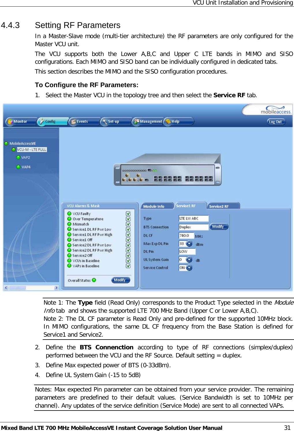
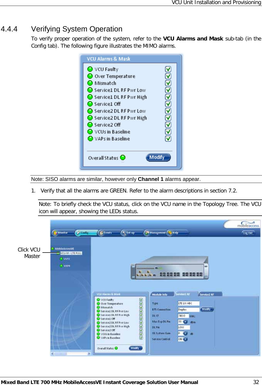
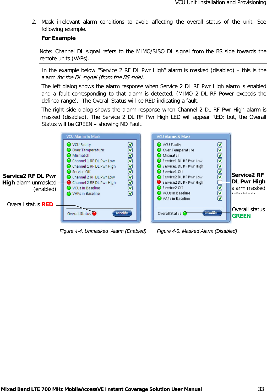
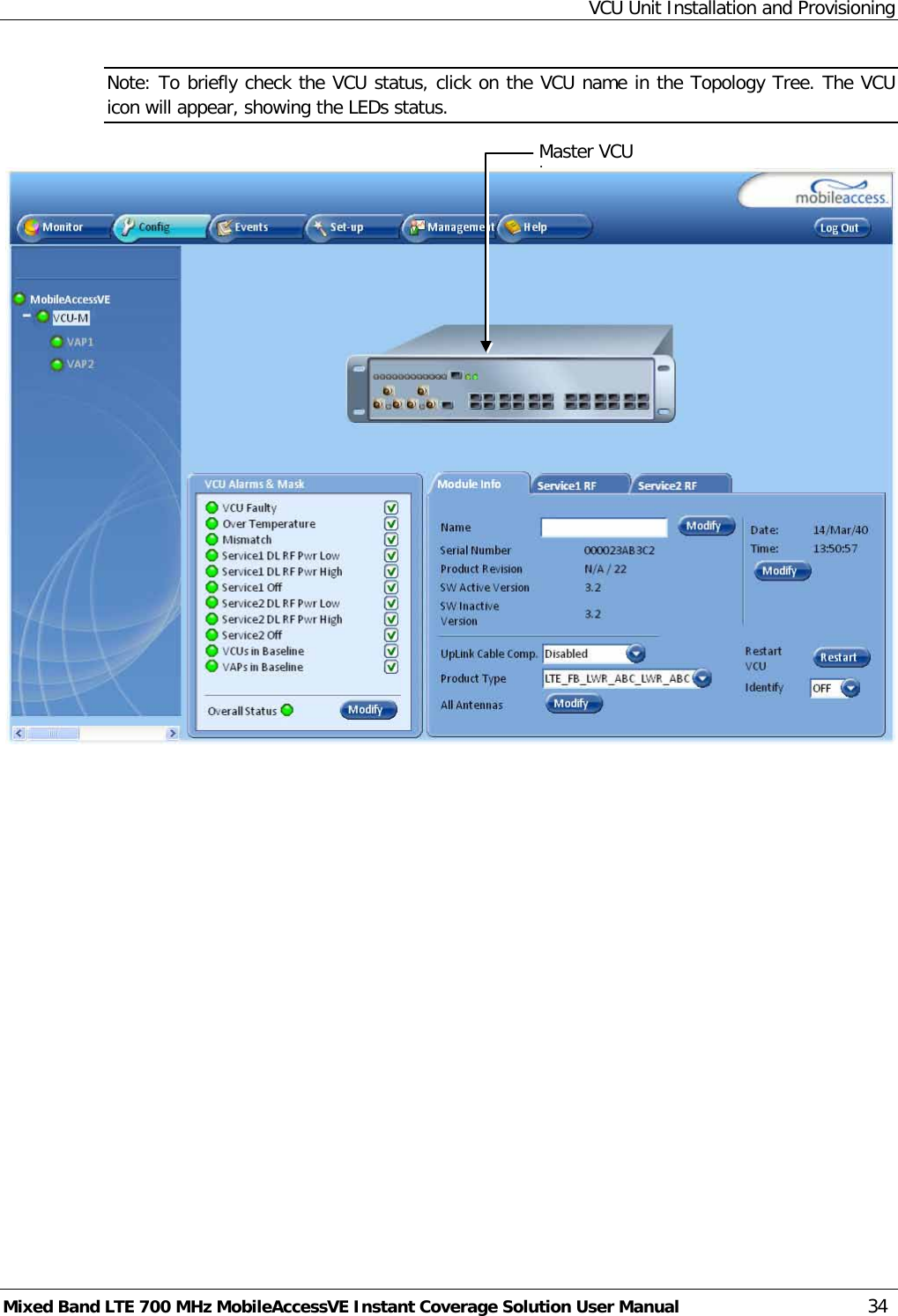
Corning Optical Communication Wireless VELTE700MB VE LTE 700MHz MIXED BAND MIMO User Manual VE Multi Band LTE 700 MHz MIMO
Corning Optical Communication Wireless VE LTE 700MHz MIXED BAND MIMO VE Multi Band LTE 700 MHz MIMO
UserManual.wiki
>
Corning Optical Communication Wireless
>
VELTE700MB User Manual
Users Manual
Navigation menu
Upload a User Manual
Namespaces
Wiki Guide
HTML
PDF
Info
Views
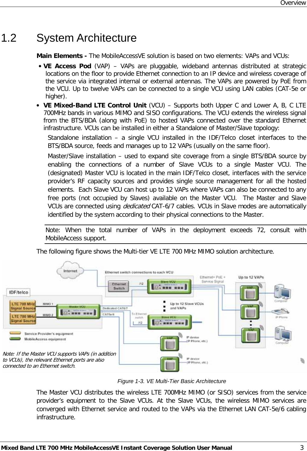
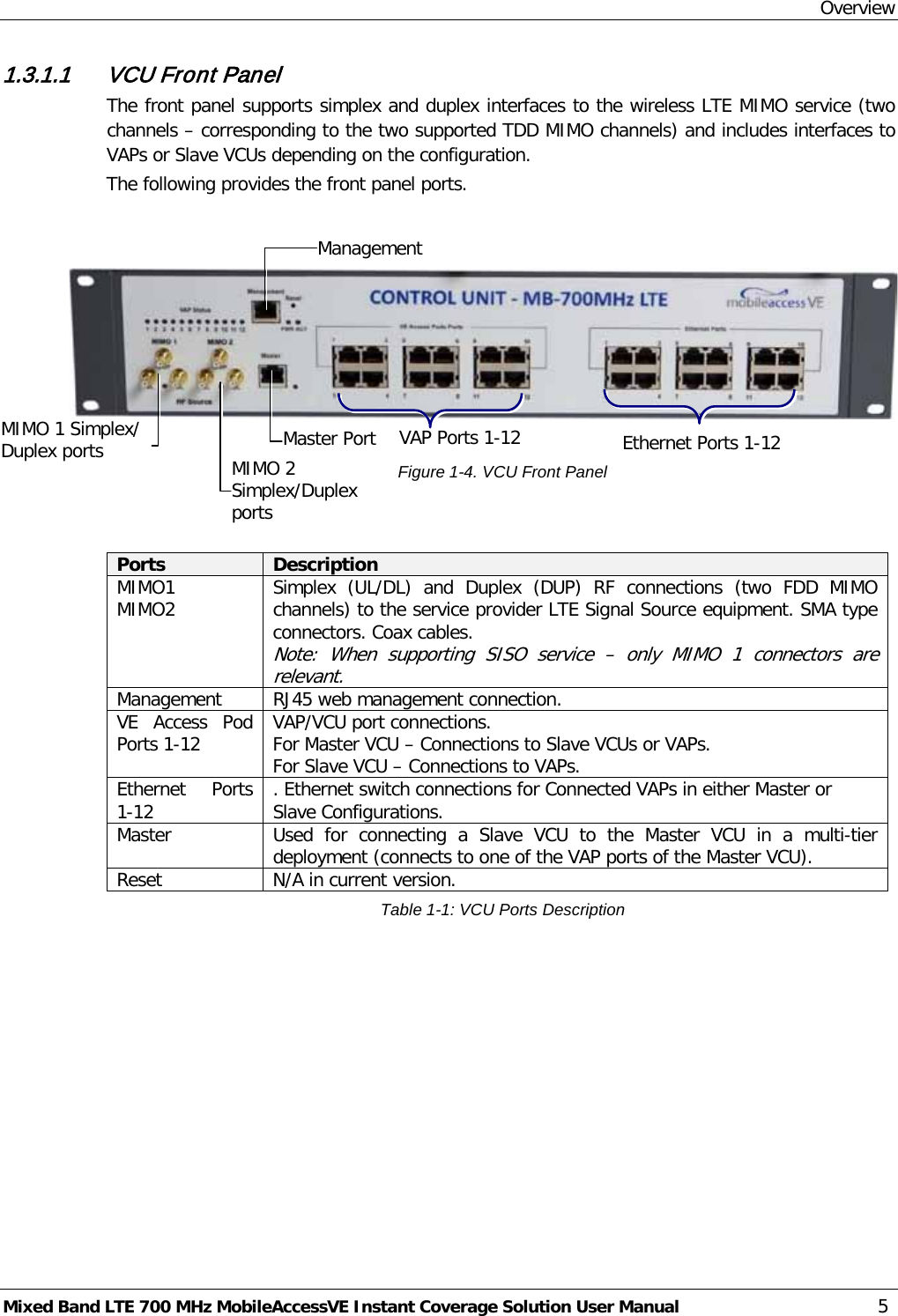
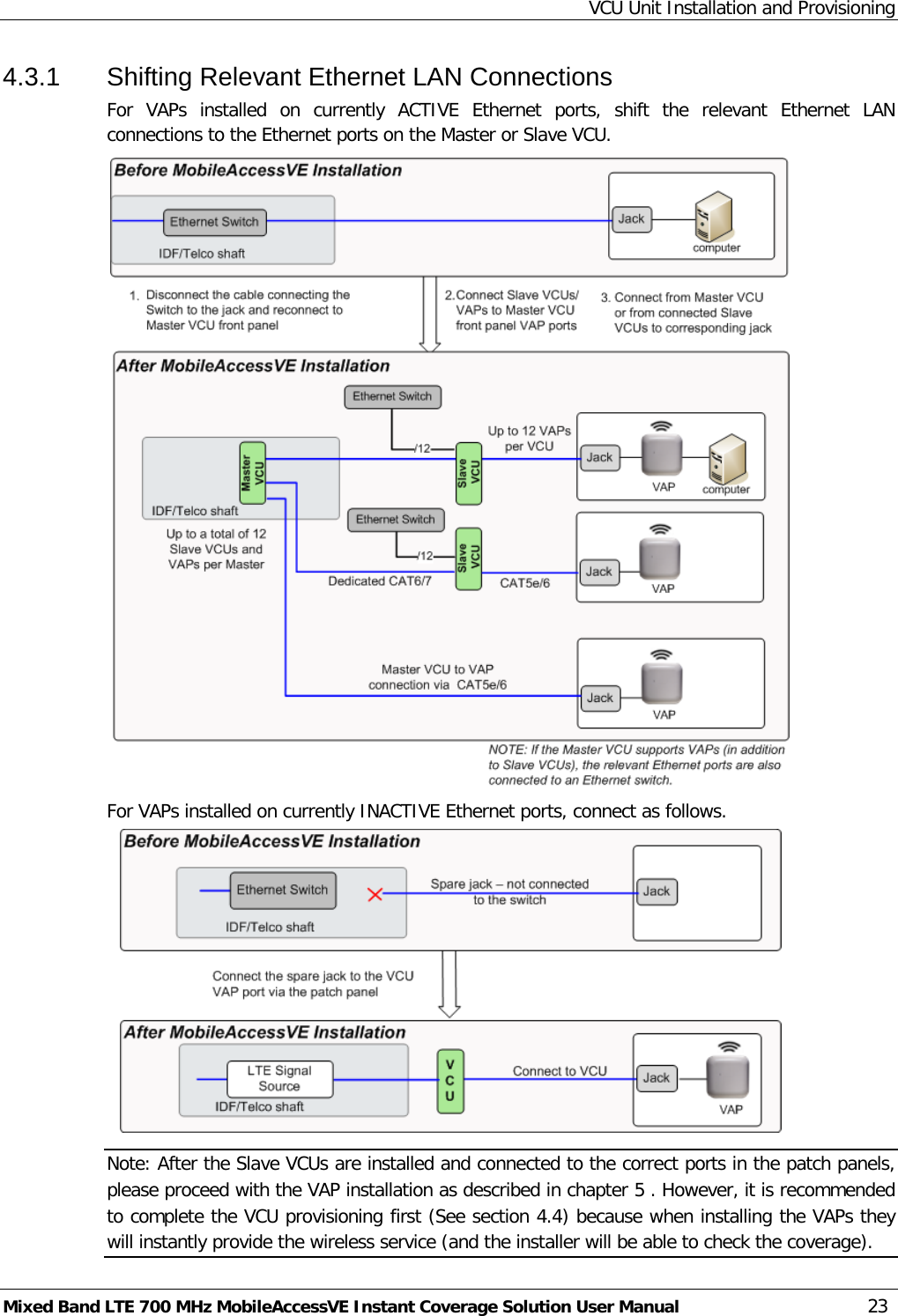
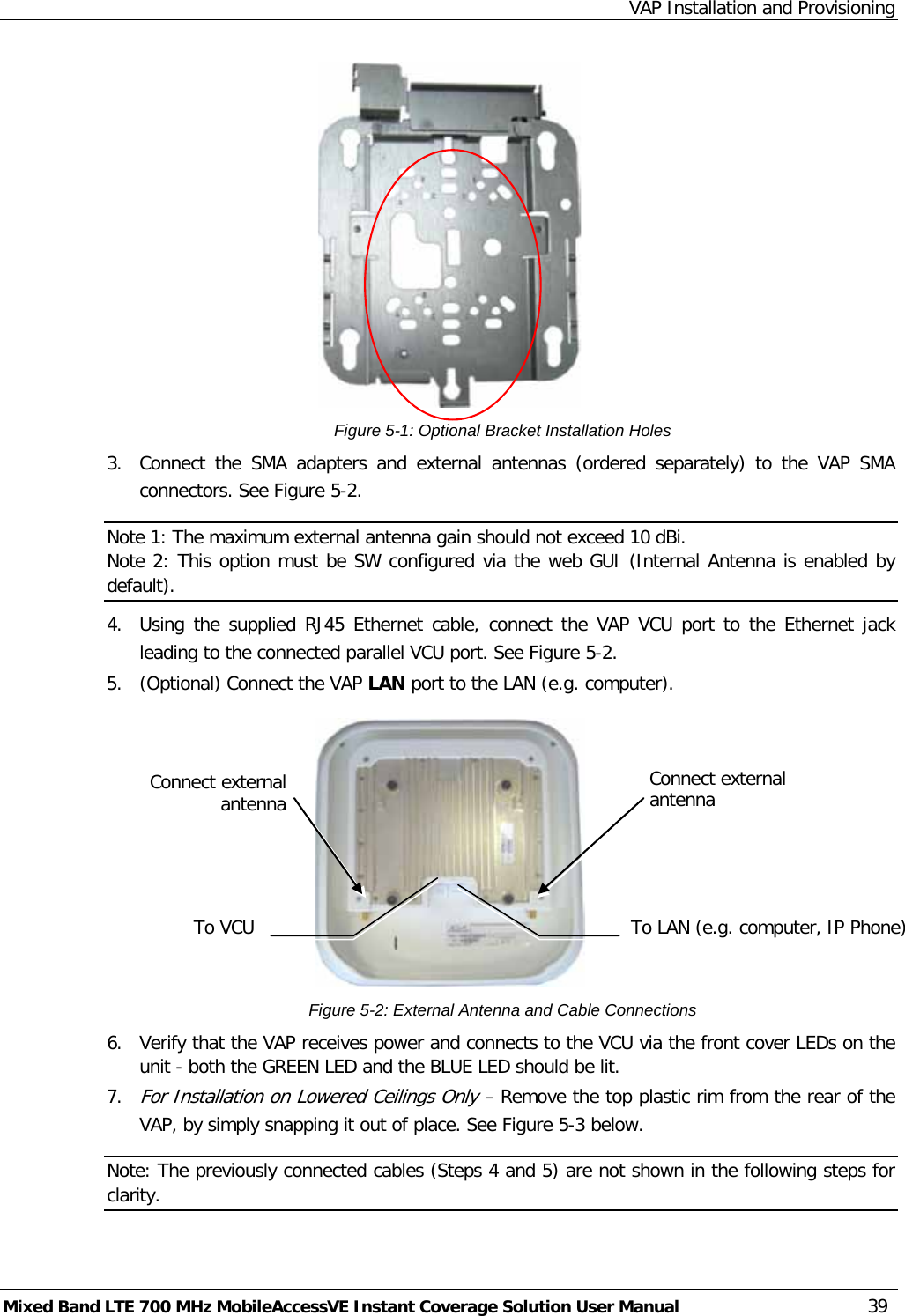
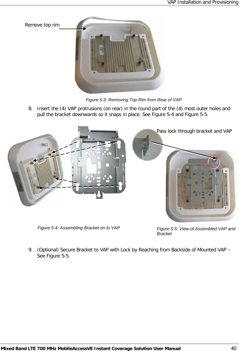
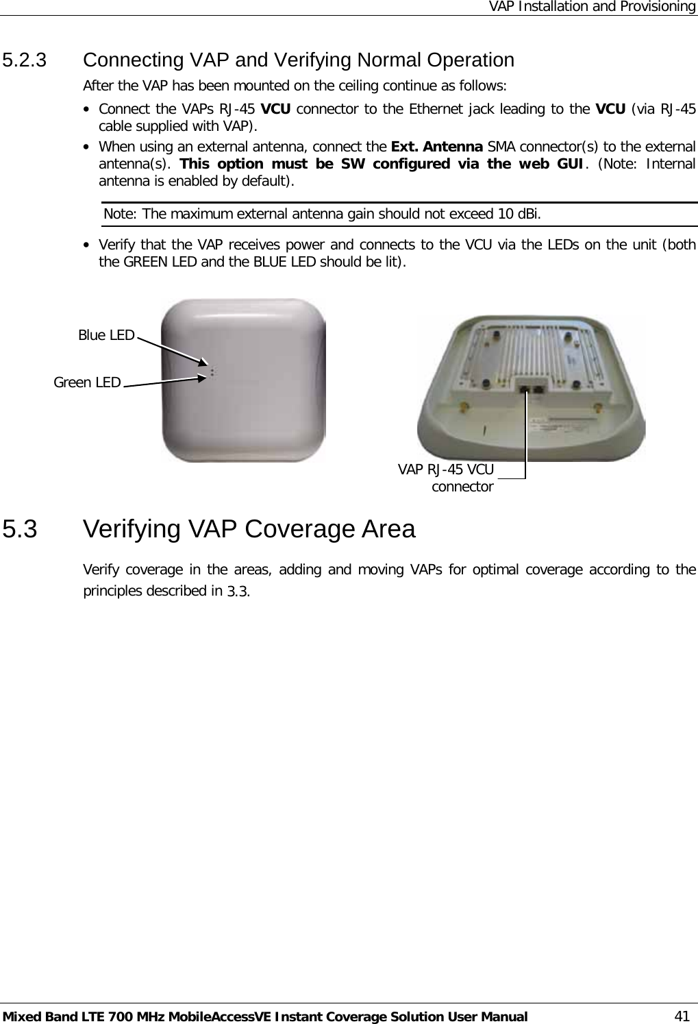
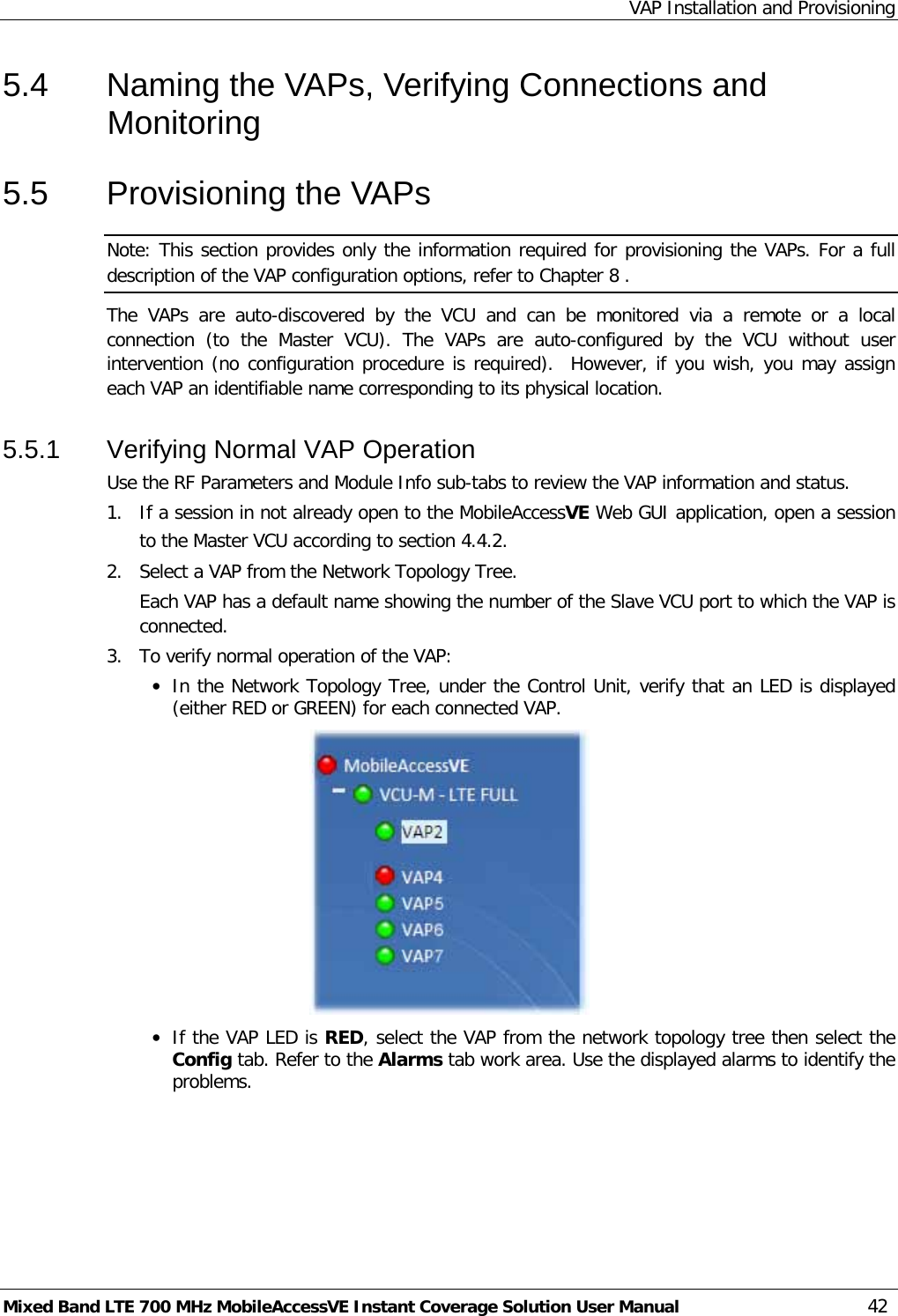
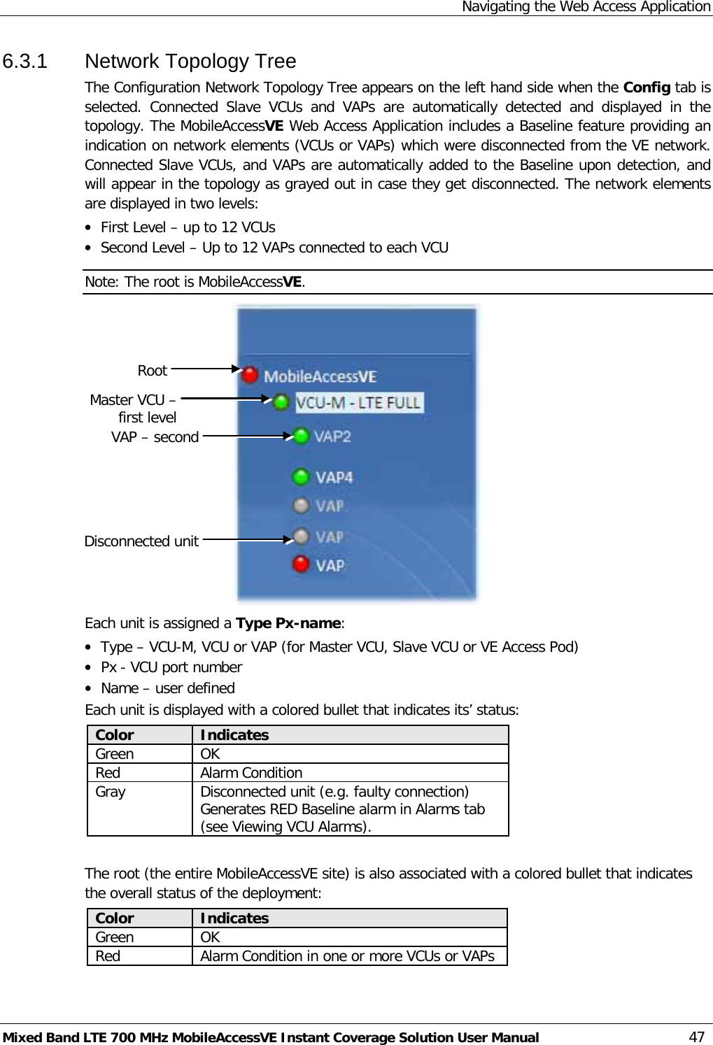
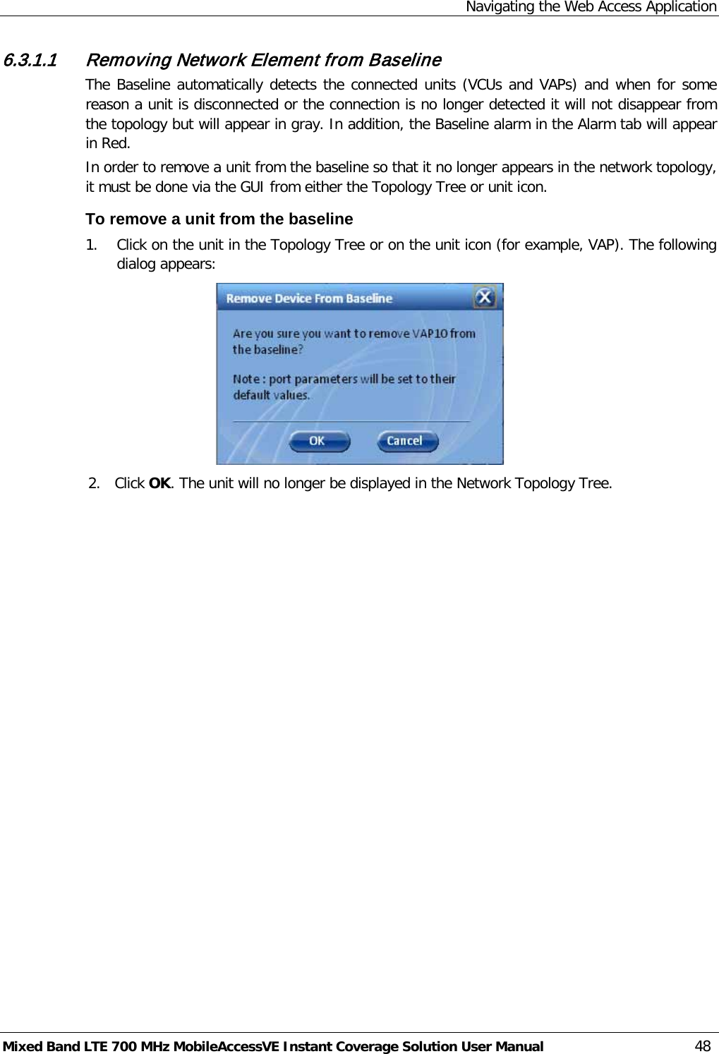
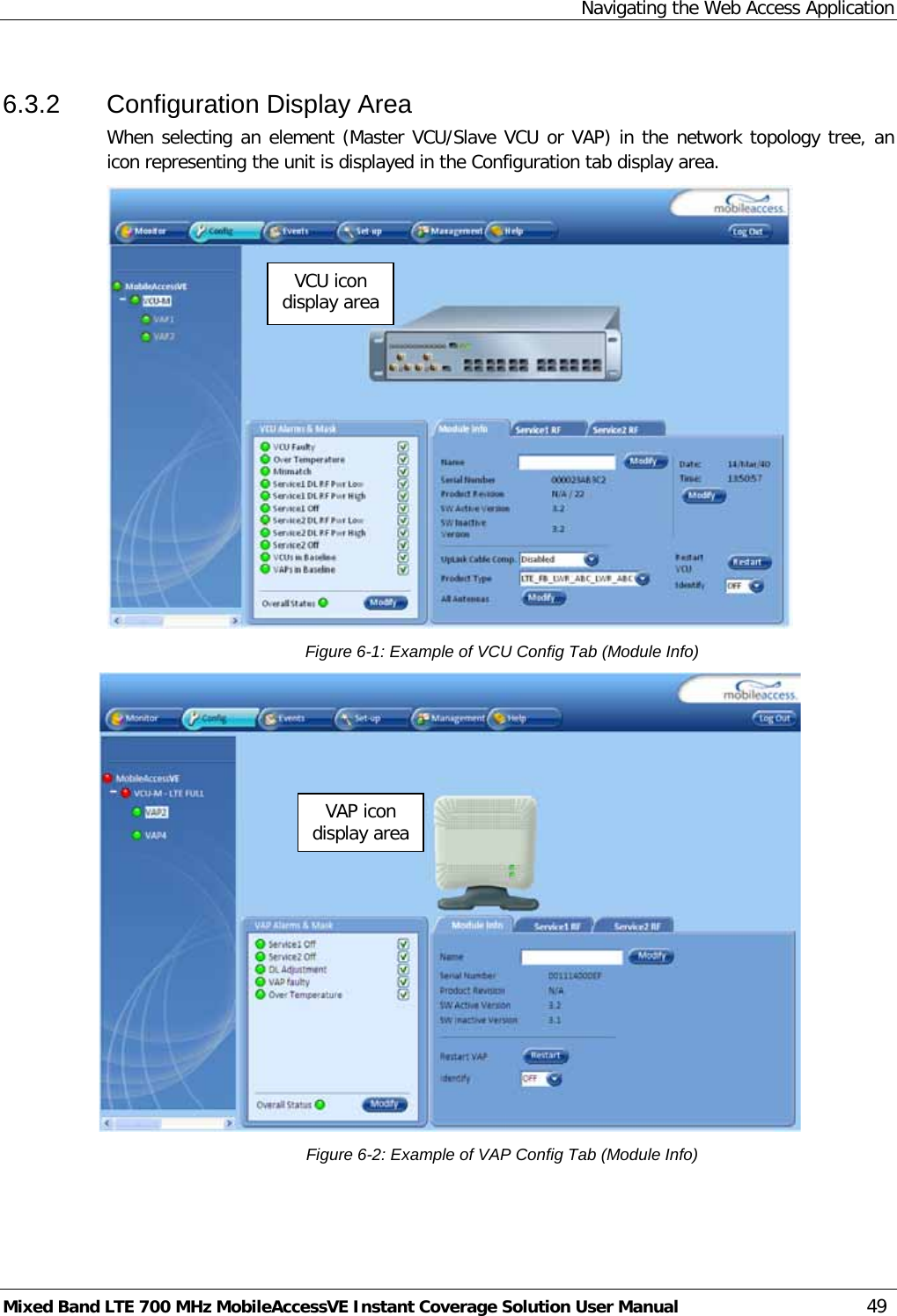
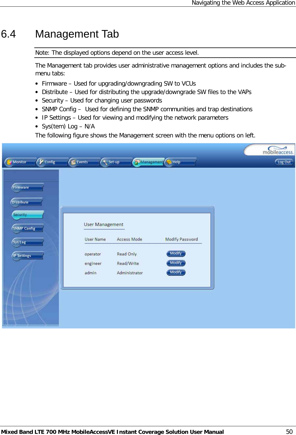
User Manual
Discussion / Help
Navigation