Corning Optical Communication 1MRU70 ONE -MRU LTE700 User Manual ONE Wireless Platform
Corning Optical Communication Wireless ONE -MRU LTE700 ONE Wireless Platform
UserManual.wiki
>
Corning Optical Communication
>
1MRU70 User Manual
User Manual
Navigation menu
Upload a User Manual
Namespaces
Wiki Guide
HTML
PDF
Info
Views
User Manual
Discussion / Help
Navigation
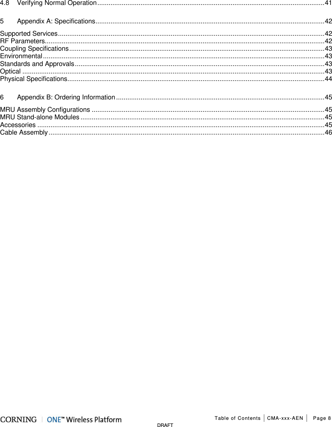
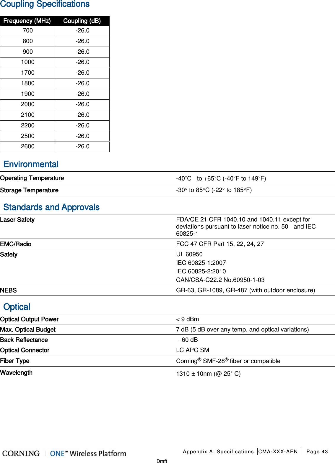
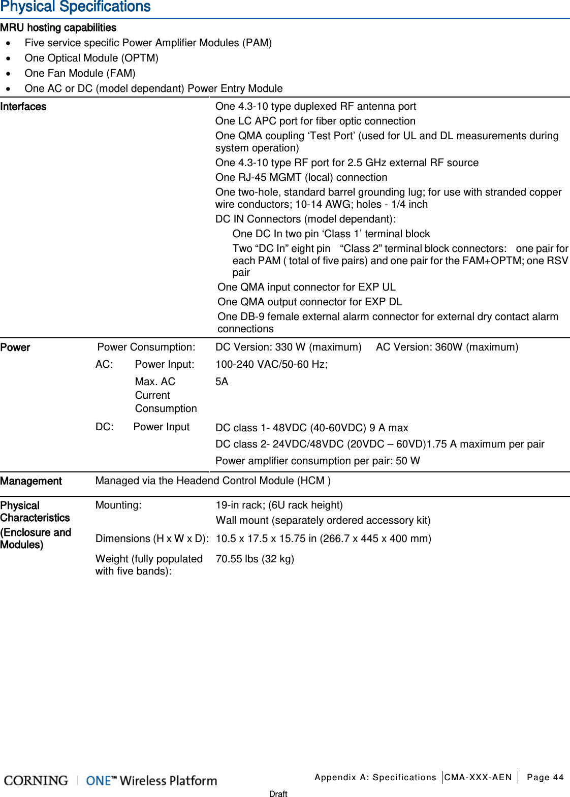
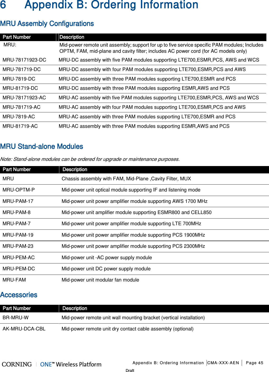
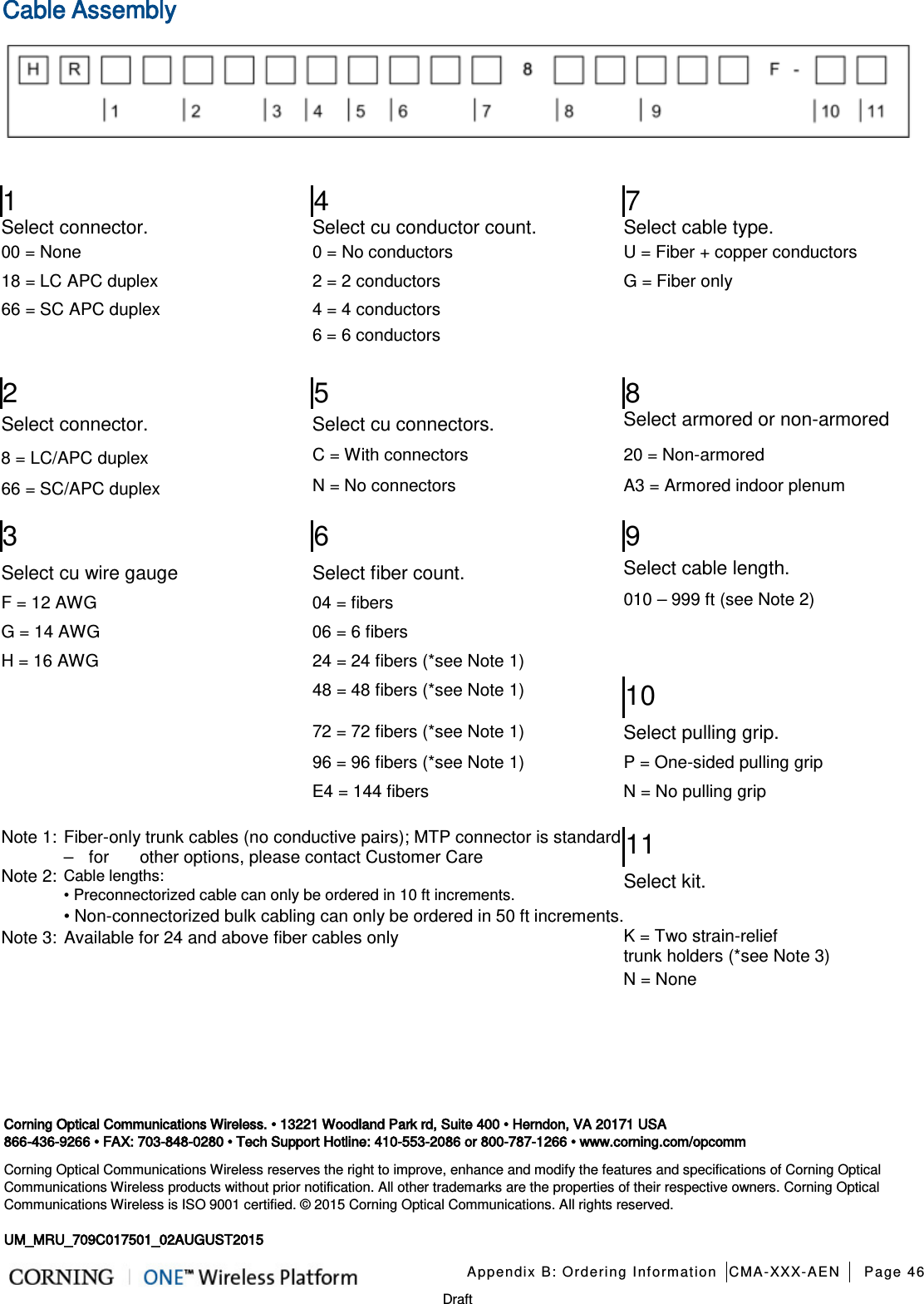
![Appendix A: Specifications CMA-XXX-AEN Page 42 Draft 5 Appendix A: Specifications Supported Services Technology Frequency Range (MHz) Service/Band Uplink (UL) Downlink (DL) LTE 700 MHz Lower ABC 700 MHz Upper C 698-716 776-787 728-746 746-757 CDMA/LTE ESMR 800 817-824 862- 869 CDMA/GSM/LTE/UMTS CELL 850 824-849 869-894 CDMA/LTE/GSM/UMTS PCS + G 1900 1850-1915 1930-1995 UMTS/LTE AWS 2100 1710-1755 2110-2155 LTE WCS 2305-2315 2350-2360 RF Parameters Service/Band LTE 700 MHz ESMR800/ CELL850 MHz PCS 1900 MHz AWS 2100 MHz WCS 2300 MHz RF Parameter DL UL DL UL DL UL DL UL DL UL Frequency Range (MHz) 729-746 746-756 699-716 777-787 862-869/ 869-894 817-824/ 824-849 1930-1995 1850-1915 2110-2155 1710-1755 2350 - 2360 2305 - 2315 Max Output Power Per Antenna Port (dBm) 30 30 33 33 33 Input Power (dBm) 0 - 37 0 - 37 0 - 37 0 - 37 0 - 37 UL Gain Range (dB) -19 to 15 -19 to 15 -19 to 15 -19 to 15 -19 to 15 Input IP3 (dBm) AGC OFF Typical -5 -5 -5 -5 -5 Input IP3 (dBm) AGC ON Typical 5 5 5 5 5 SFDR* (dB) 60 64 64 60 60 Max Intermod Distortion [dBm] ≤ -13 ≤ -13 ≤ -13 ≤ -13 ≤ -13 UL NF*(dB) 12 12 12 12 12 Gain Flatness/Ripple (dB) ±2.0 ±2.0 ±2.0 ±2.0 ±2.0 *Typical for single Remote Access Unit ** SFDR calculated with BW of 1.23MHz for the CELL and PCS and with 5MHz for the LTE, AWS and WCS.](https://usermanual.wiki/Corning-Optical-Communication/1MRU70/User-Guide-2709380-Page-42.png)