Corning Optical Communication 1MXU25 ONE - MXU ADD-ON TDD 2496-2690MHz User Manual
Corning Optical Communication Wireless ONE - MXU ADD-ON TDD 2496-2690MHz
UserManual.wiki
>
Corning Optical Communication
>
1MXU25 User Manual
>
User Manual
Contents
1.
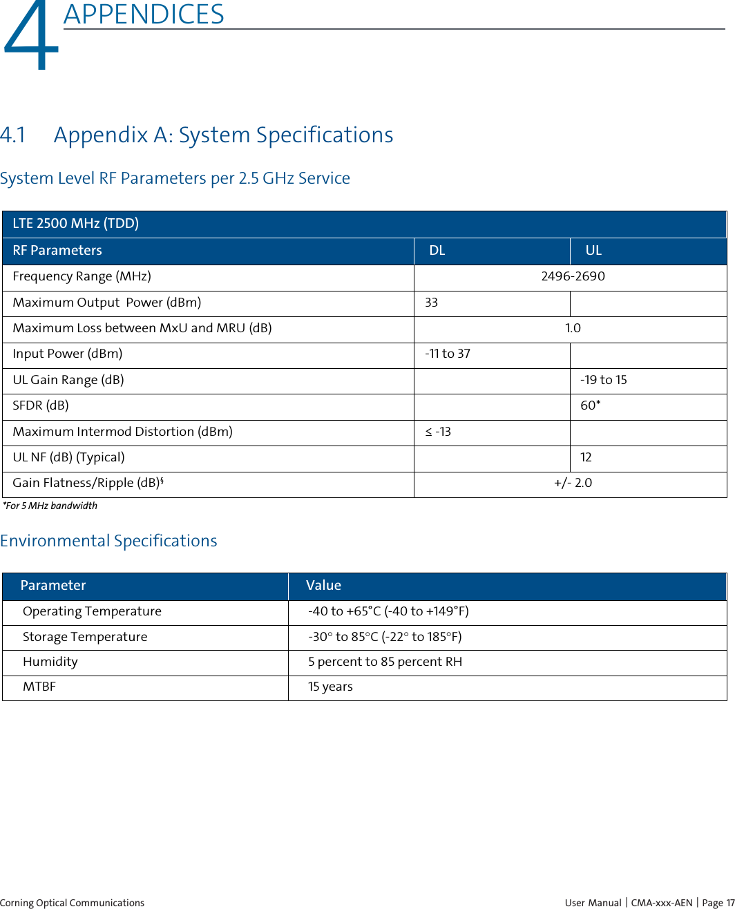
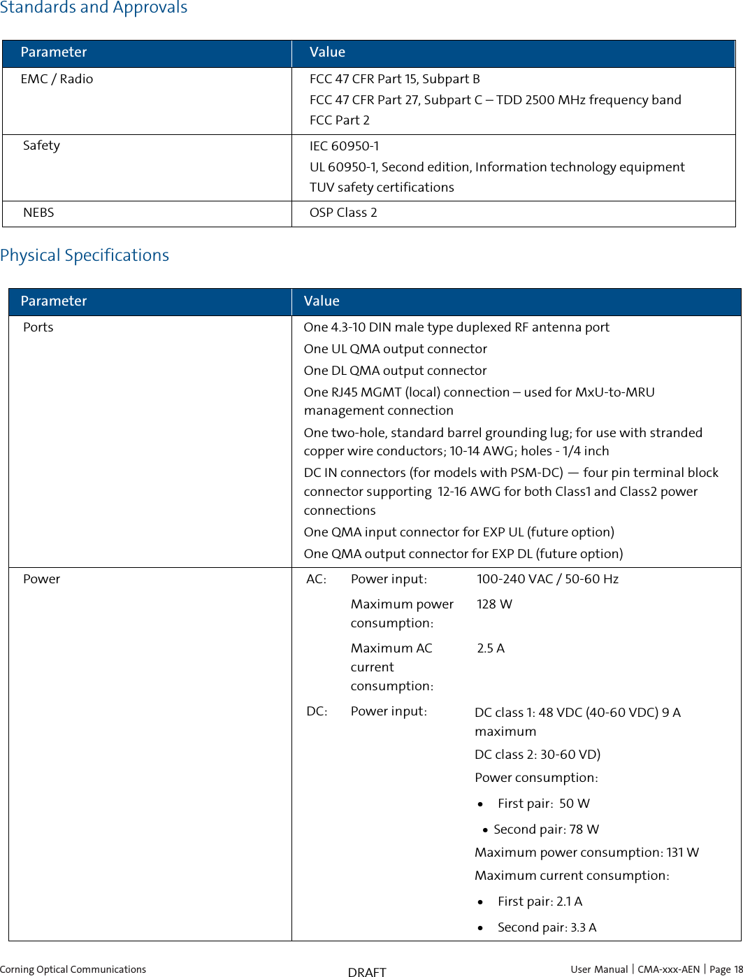
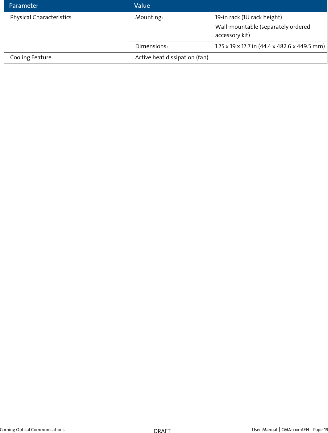
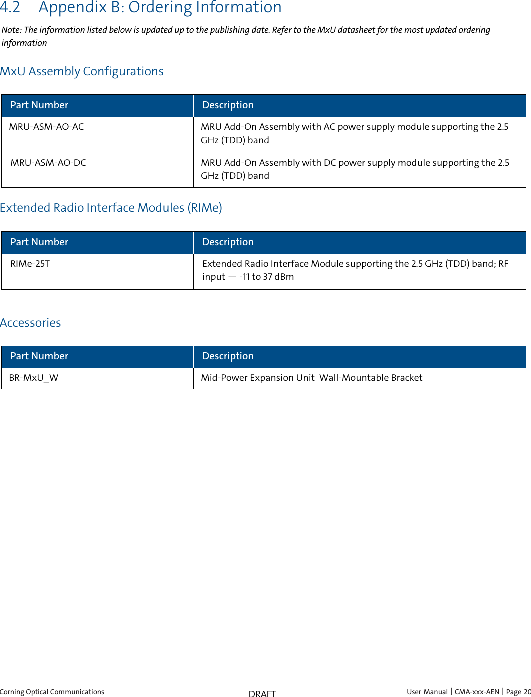
User Manual
2.
User Manual Warning Attestation
User Manual
Navigation menu
Upload a User Manual
Namespaces
Wiki Guide
HTML
PDF
Info
Views
User Manual
Discussion / Help
Navigation