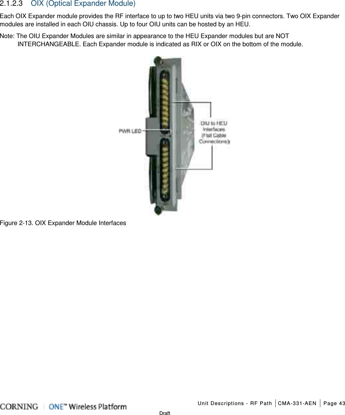
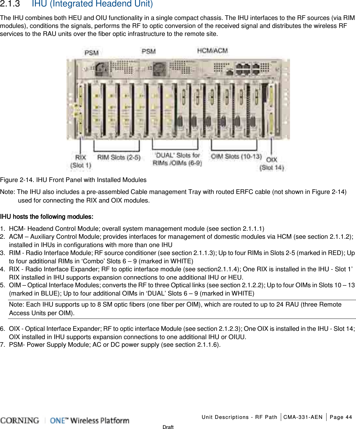
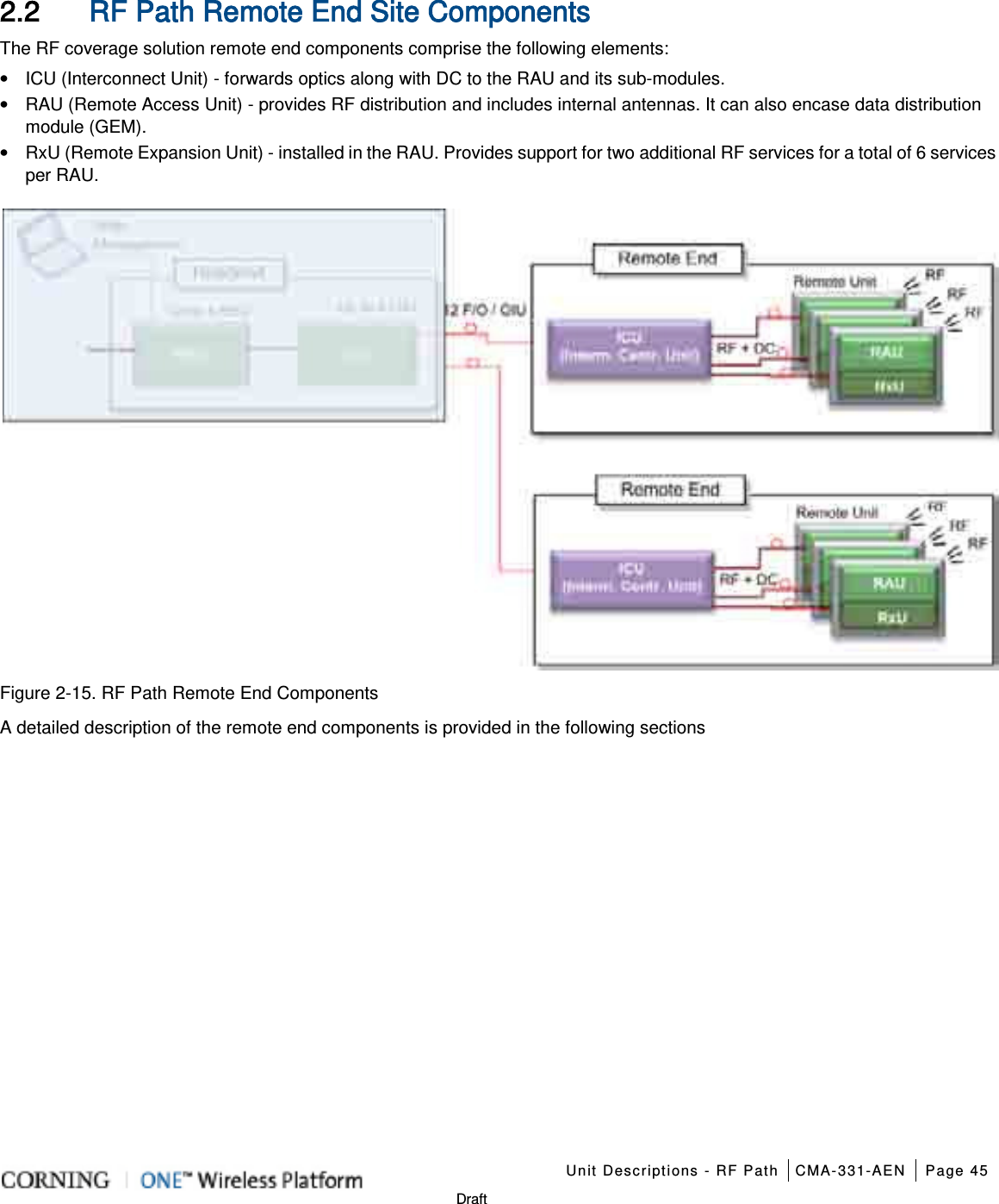
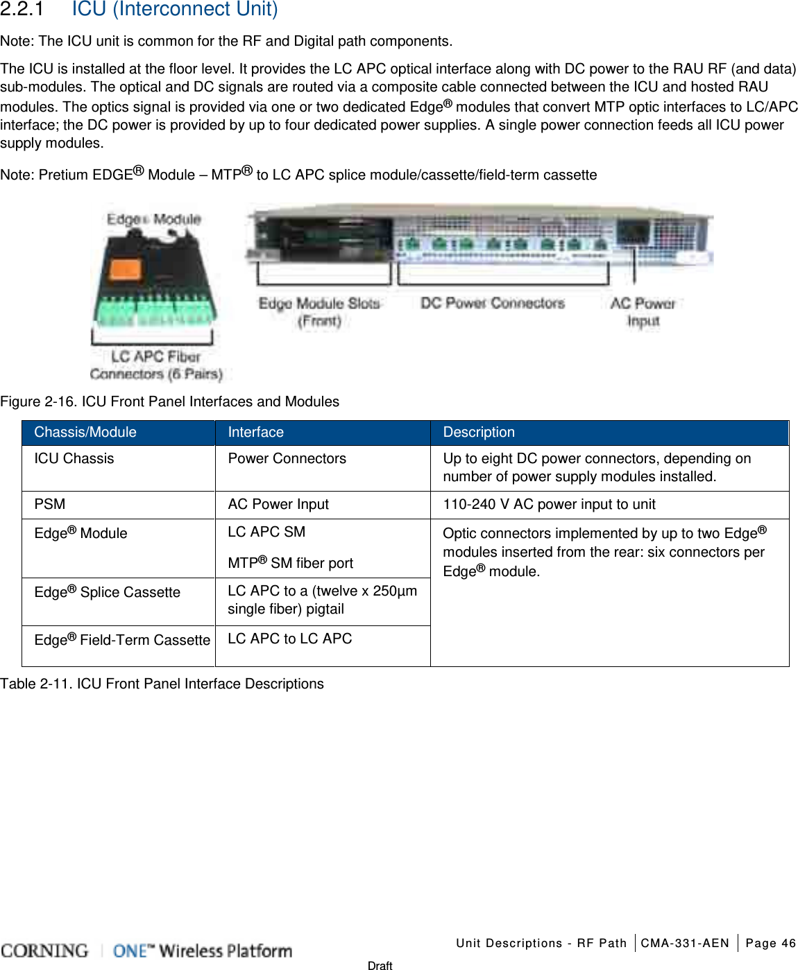
Corning Optical Communication 1RAU5 ONE Optical Network Evolution DAS RAU-5 Remote Antenna Unit User Manual ONE Wireless Platform
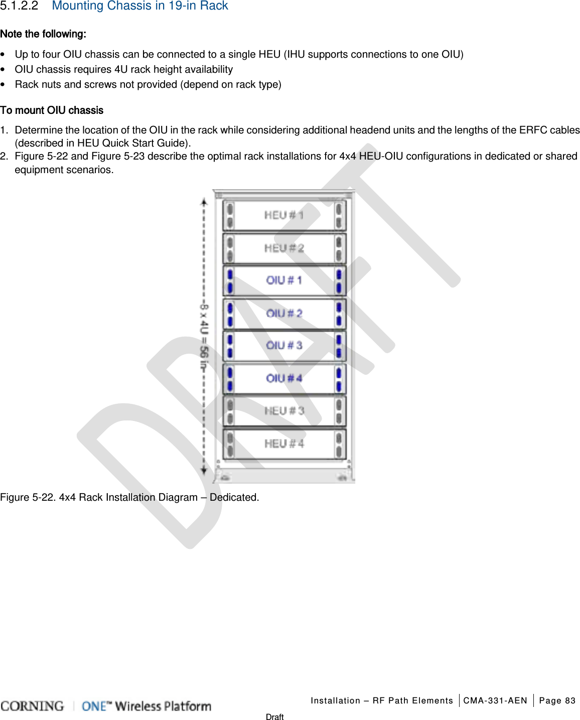
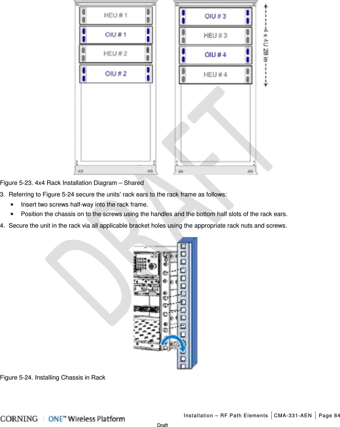
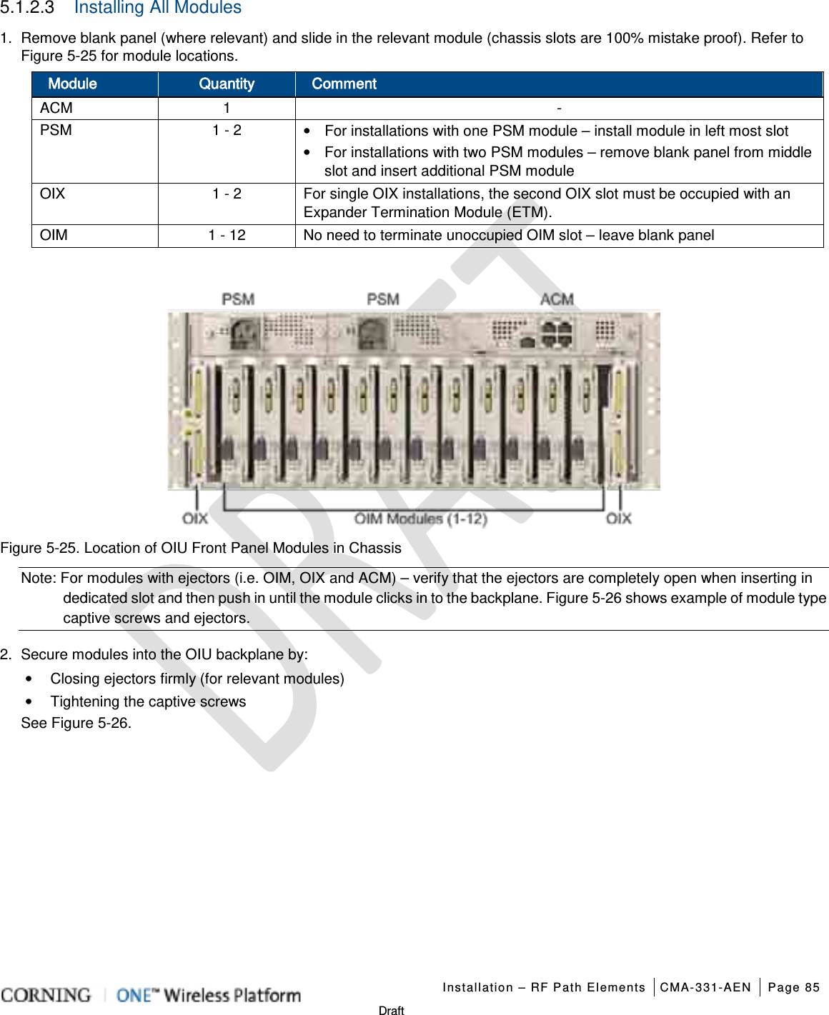
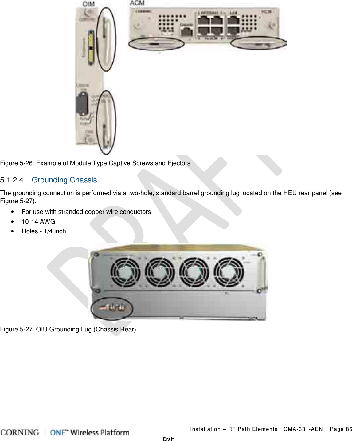
Corning Optical Communication Wireless ONE Optical Network Evolution DAS RAU-5 Remote Antenna Unit ONE Wireless Platform
User Manual
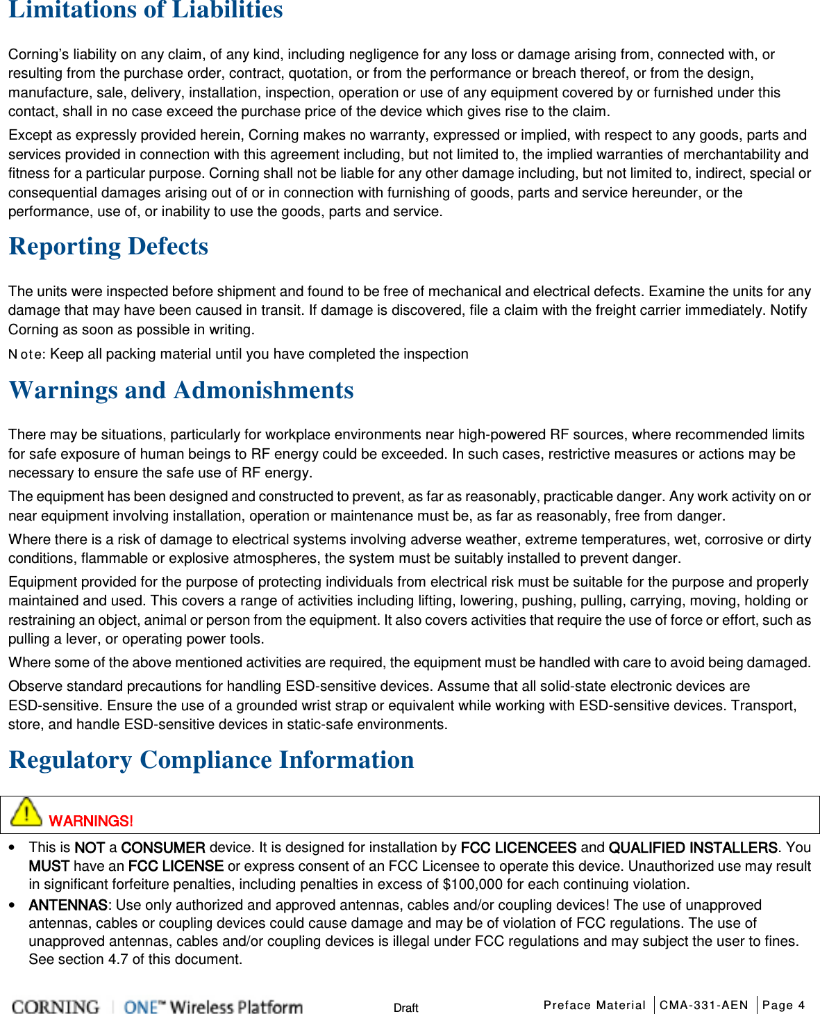
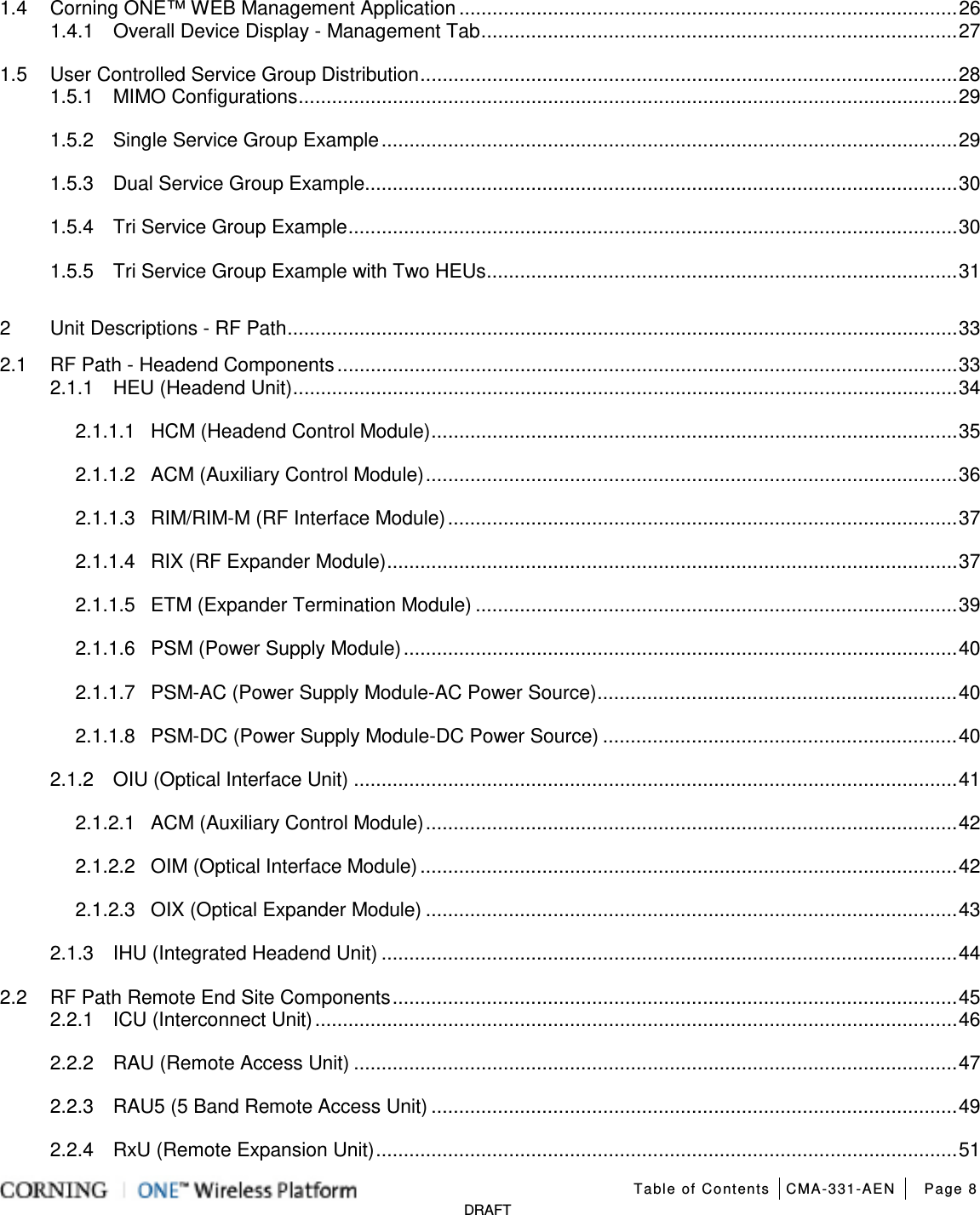
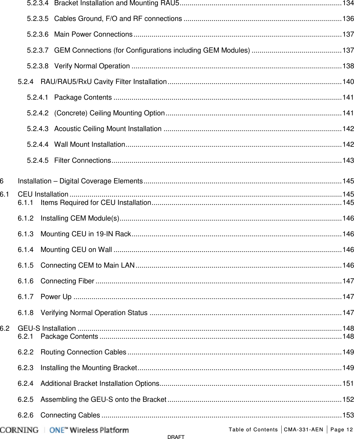
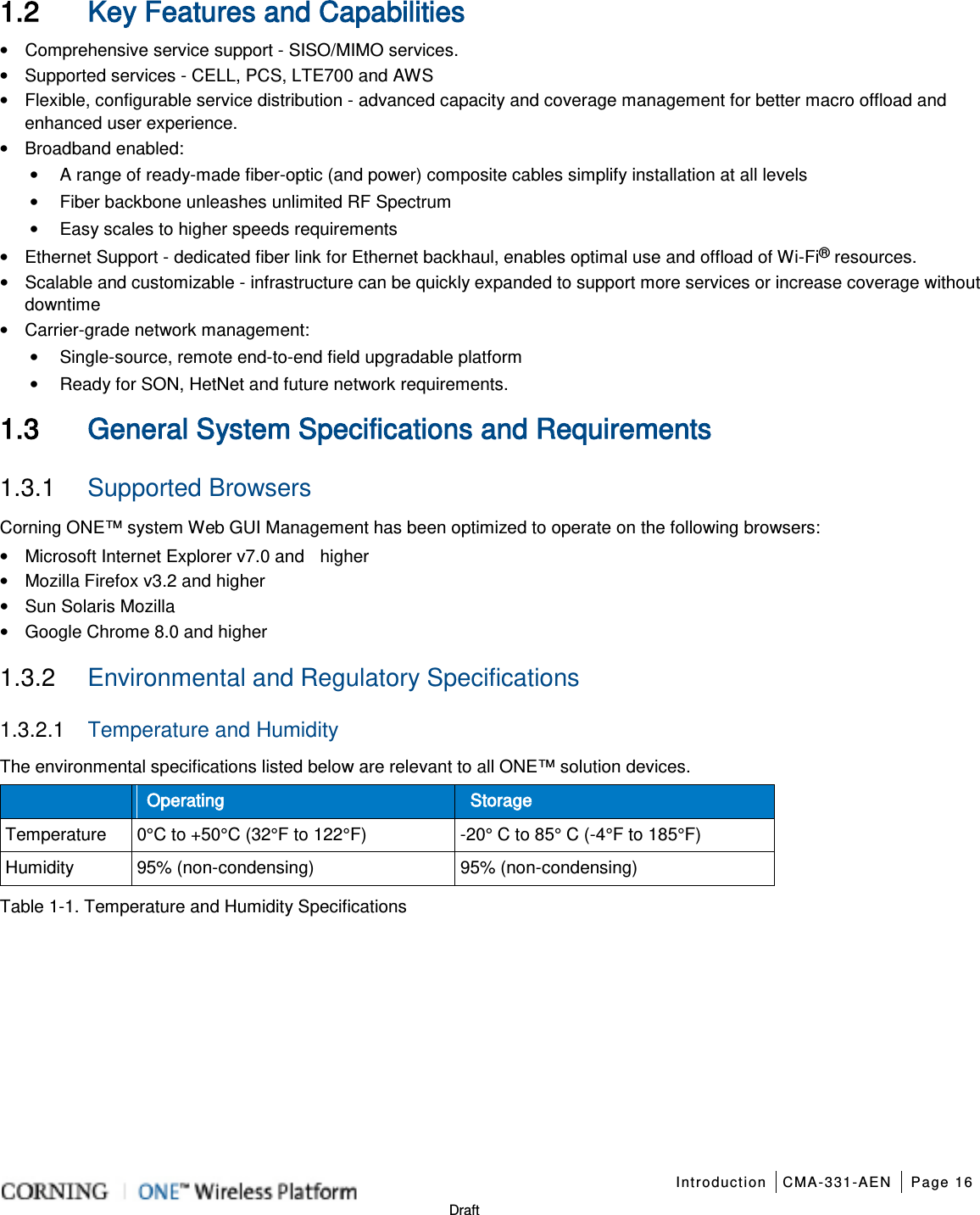
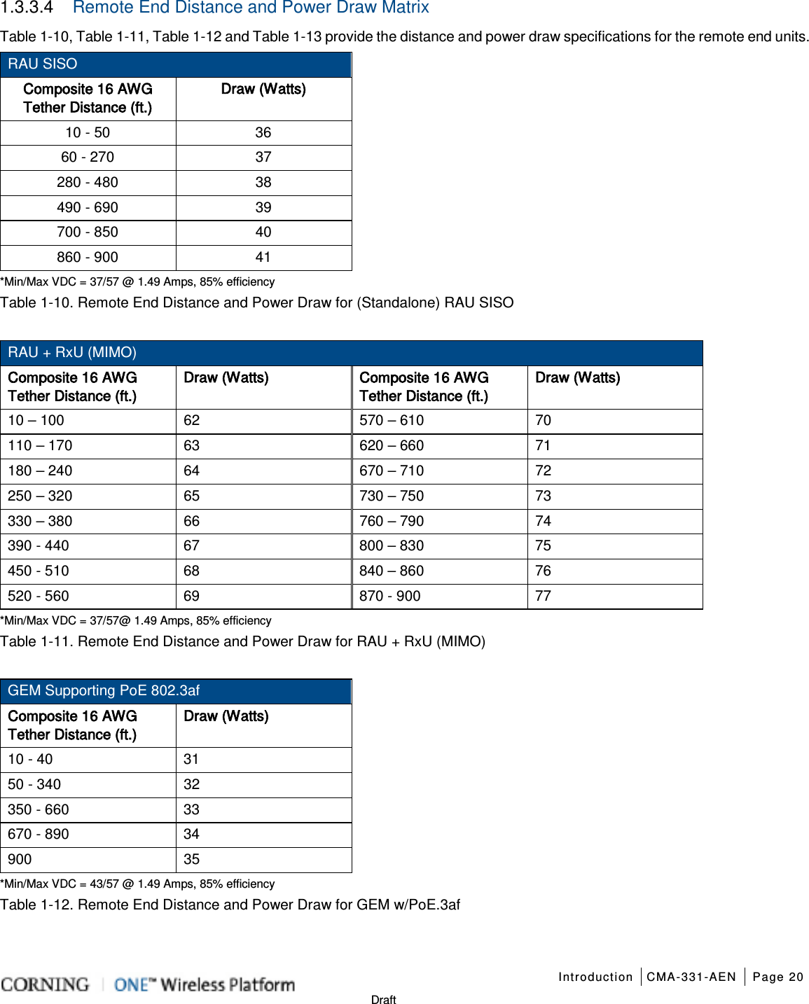
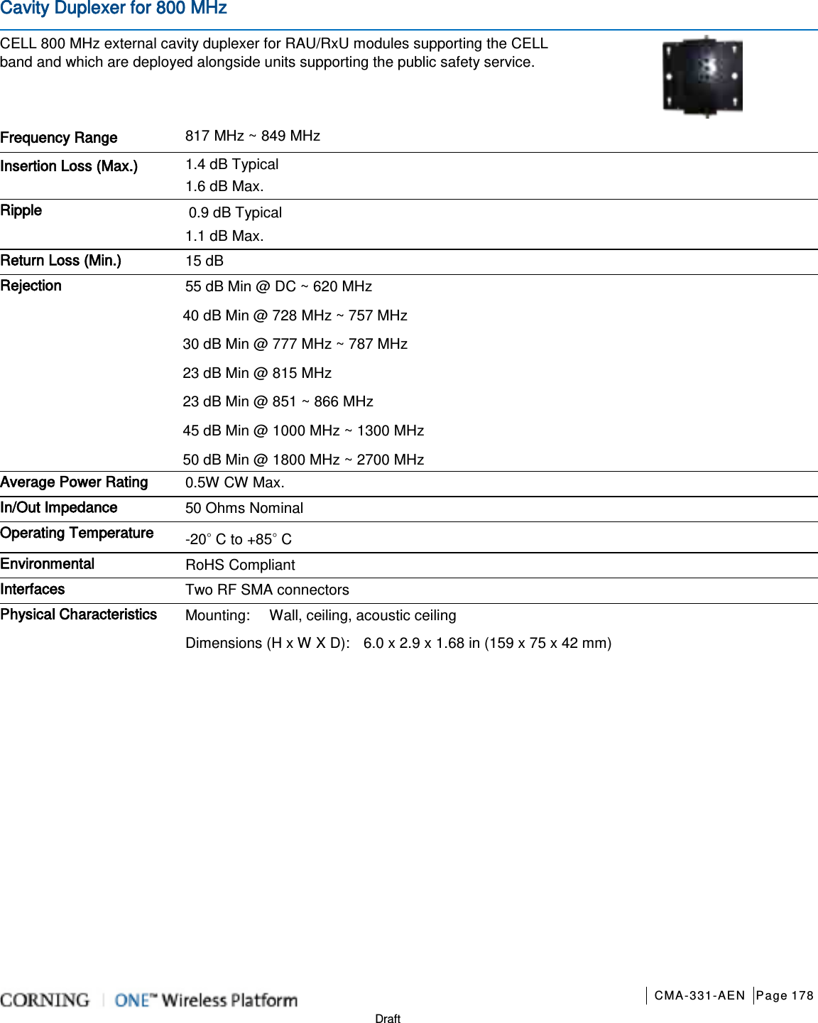
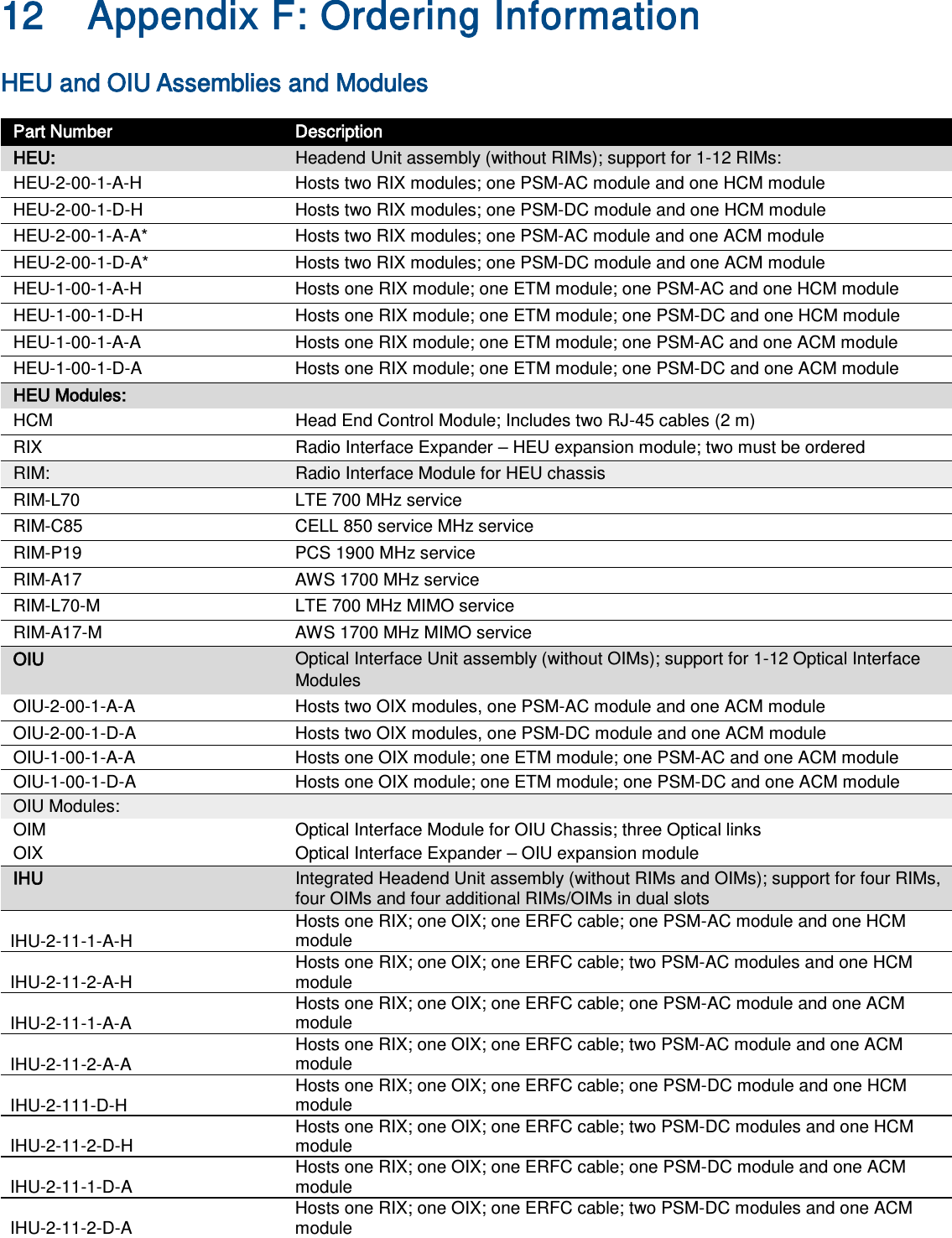
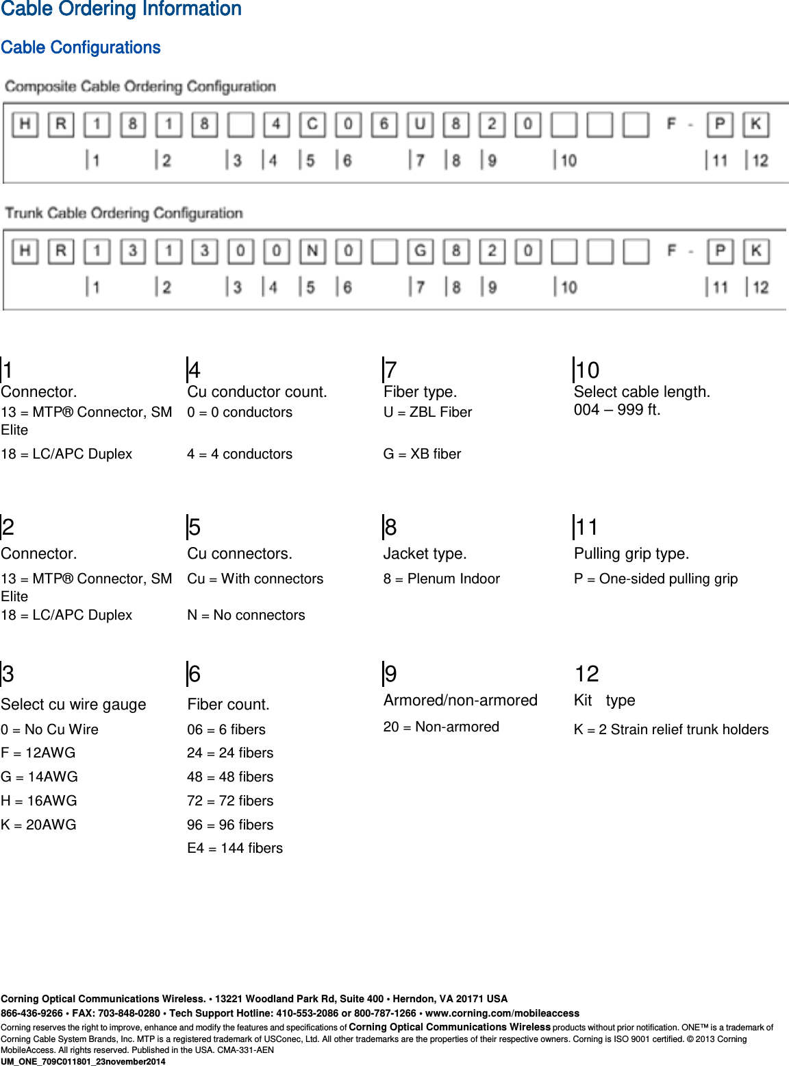
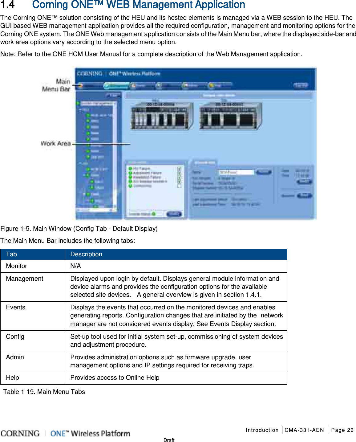
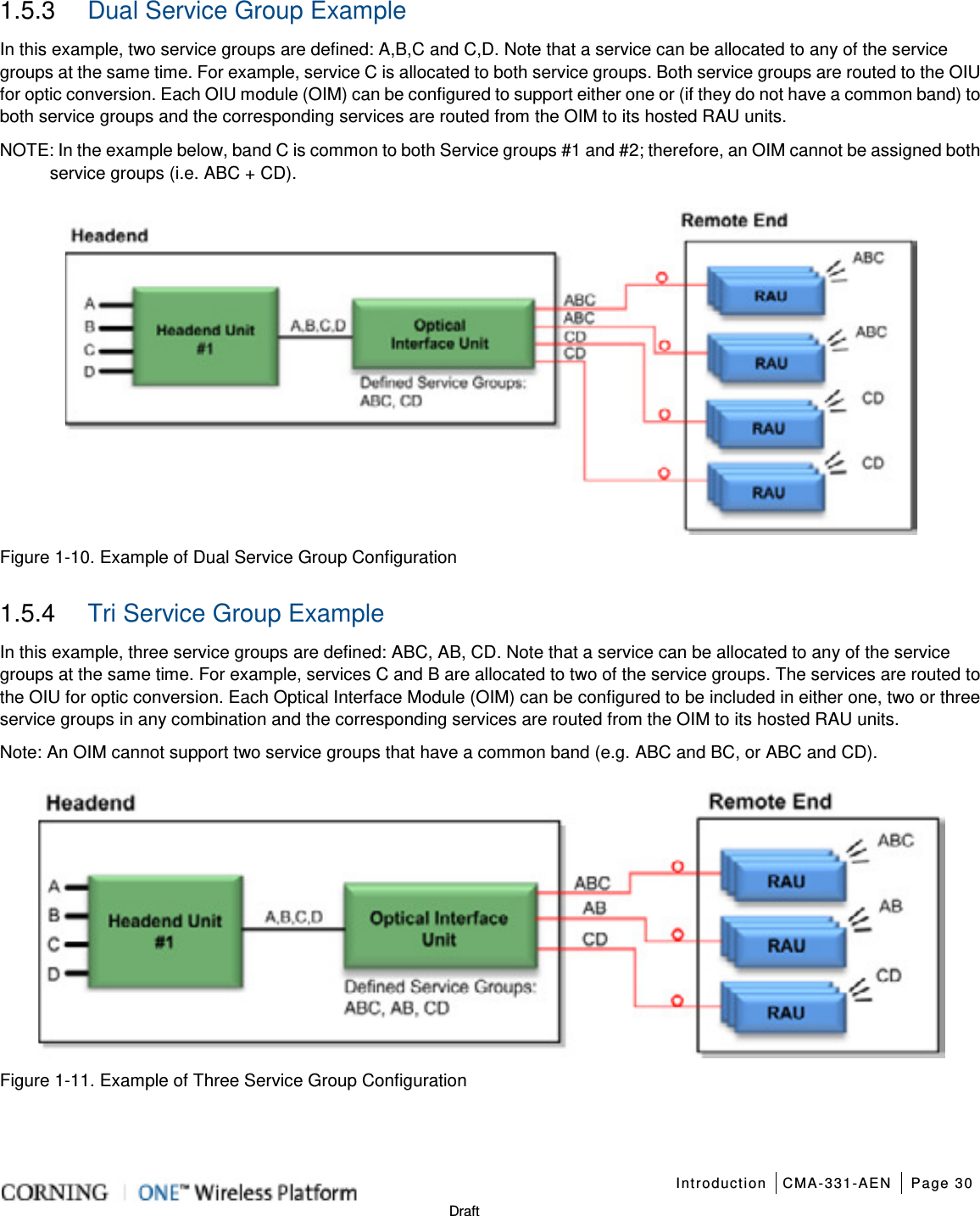
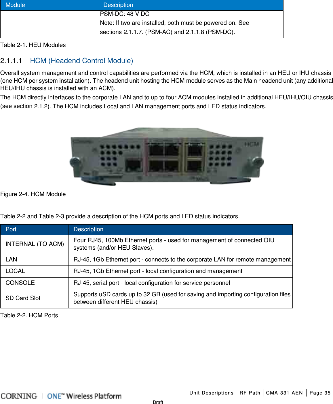
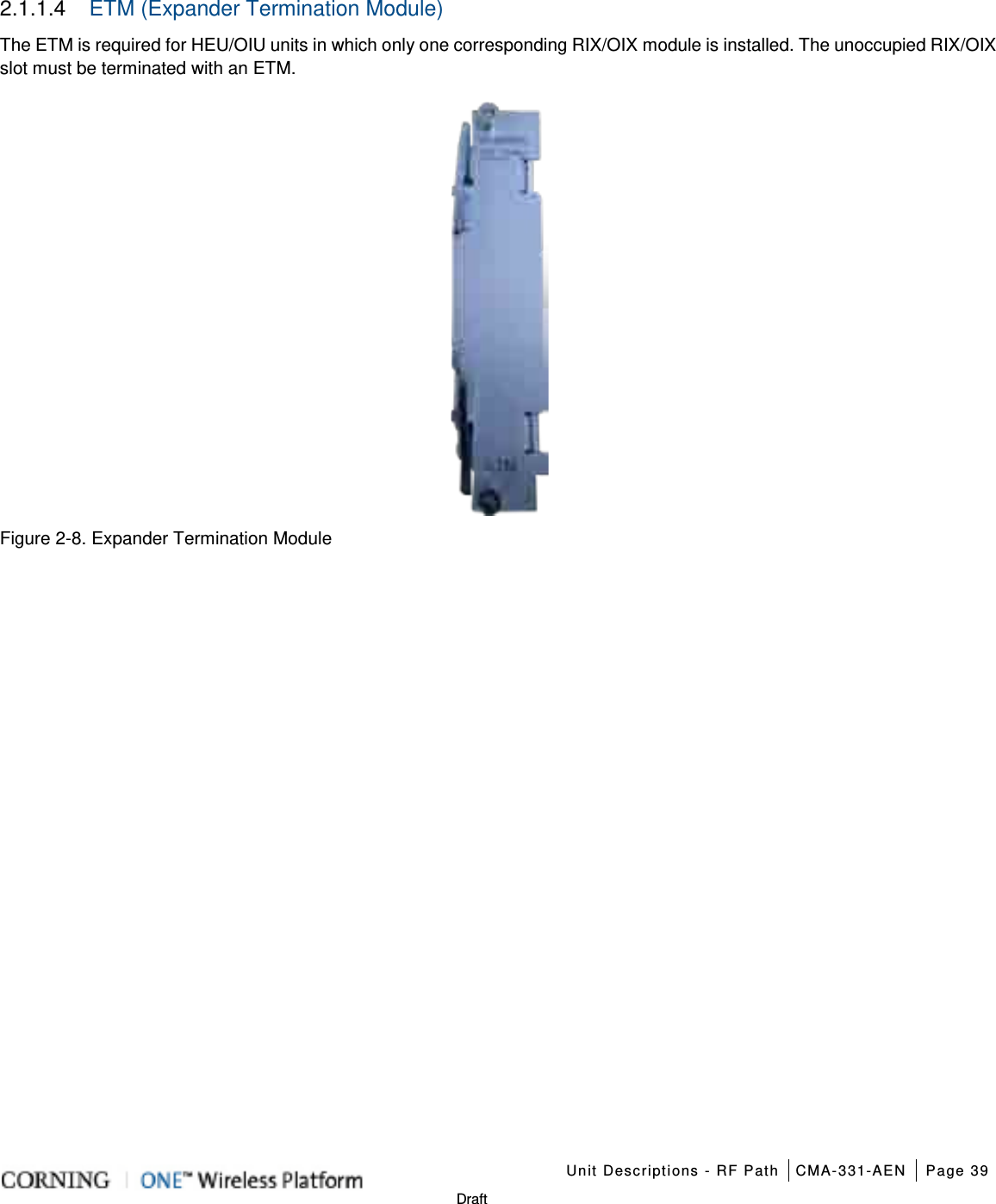
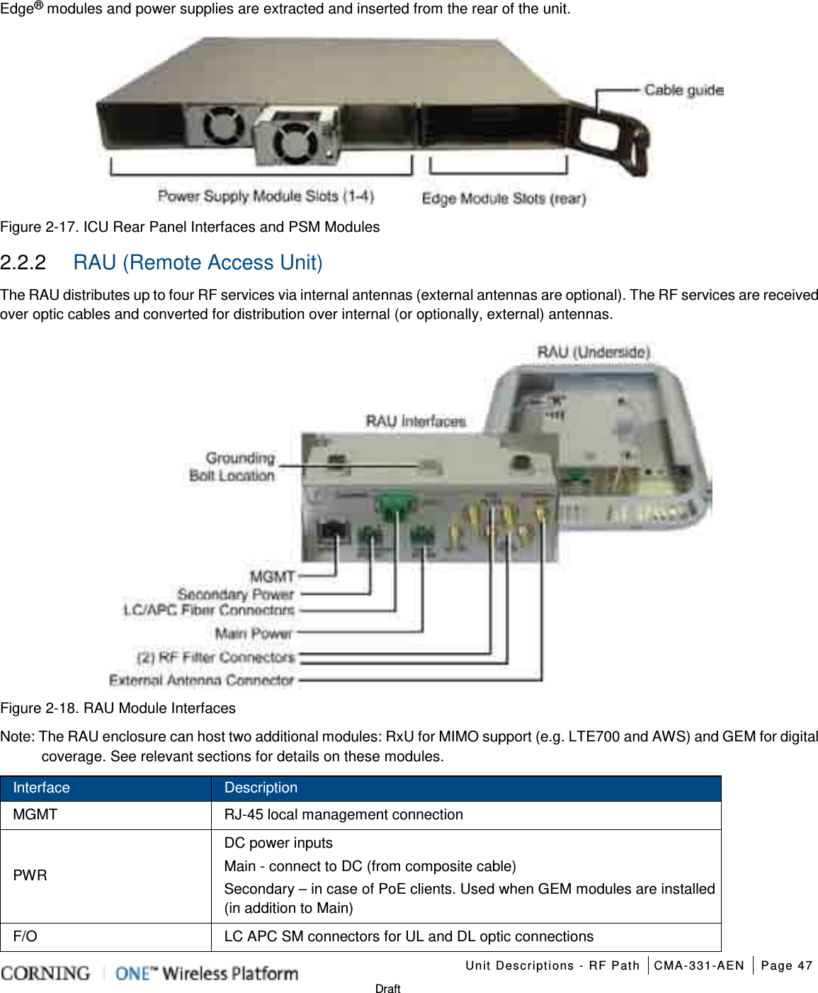
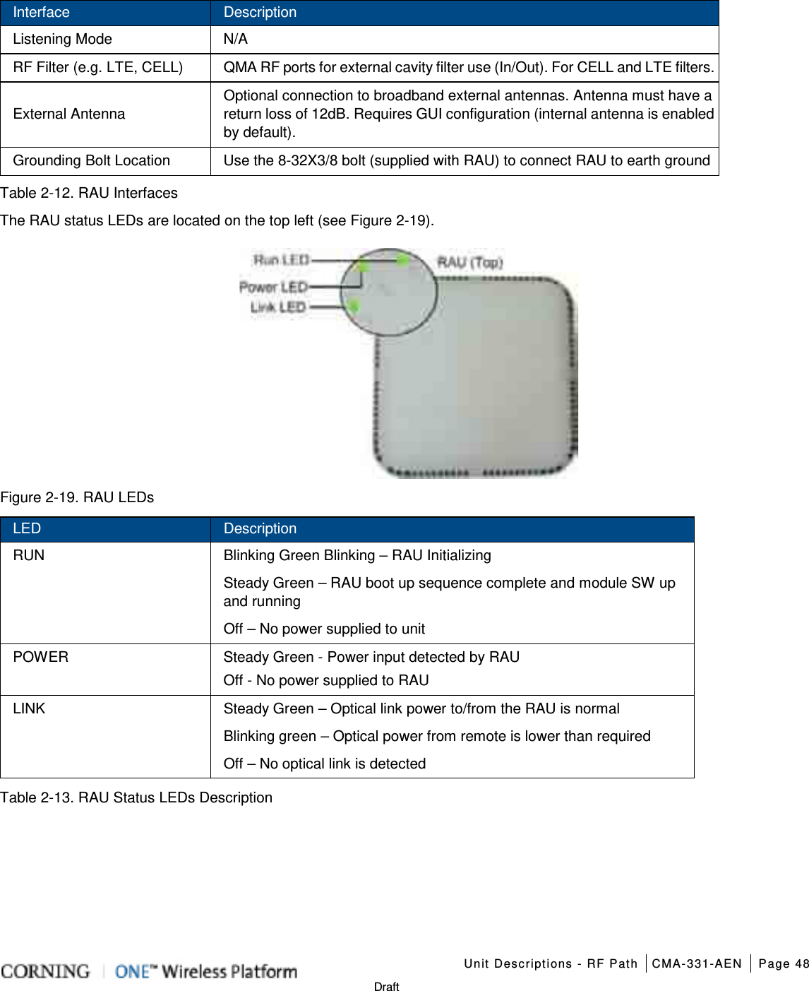
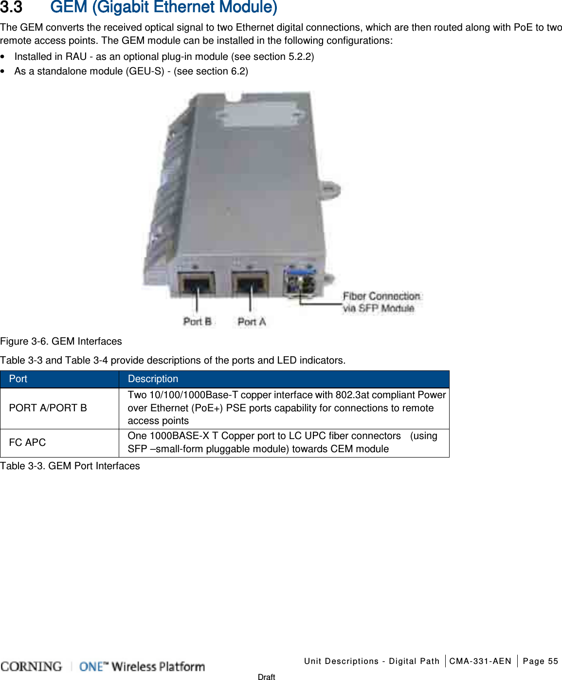
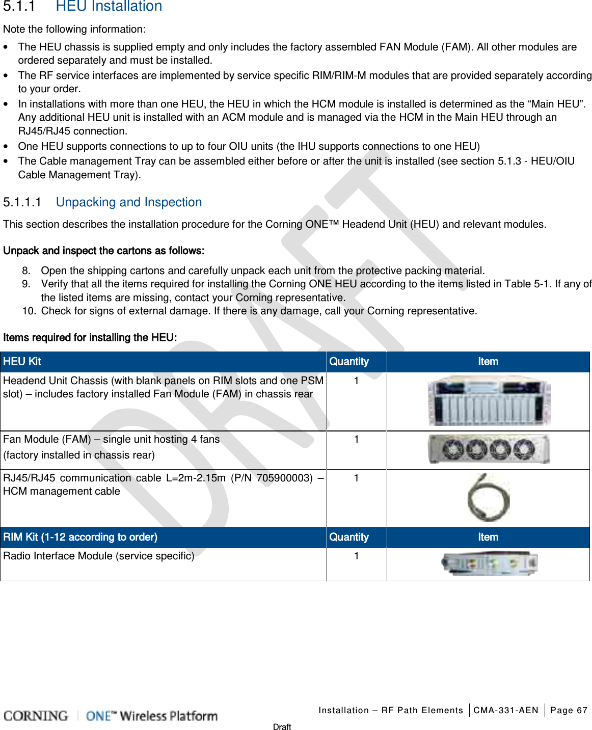
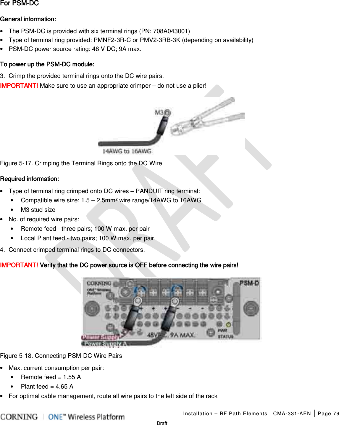
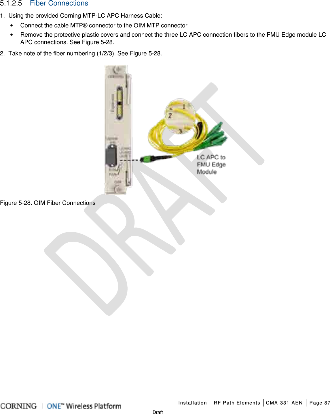
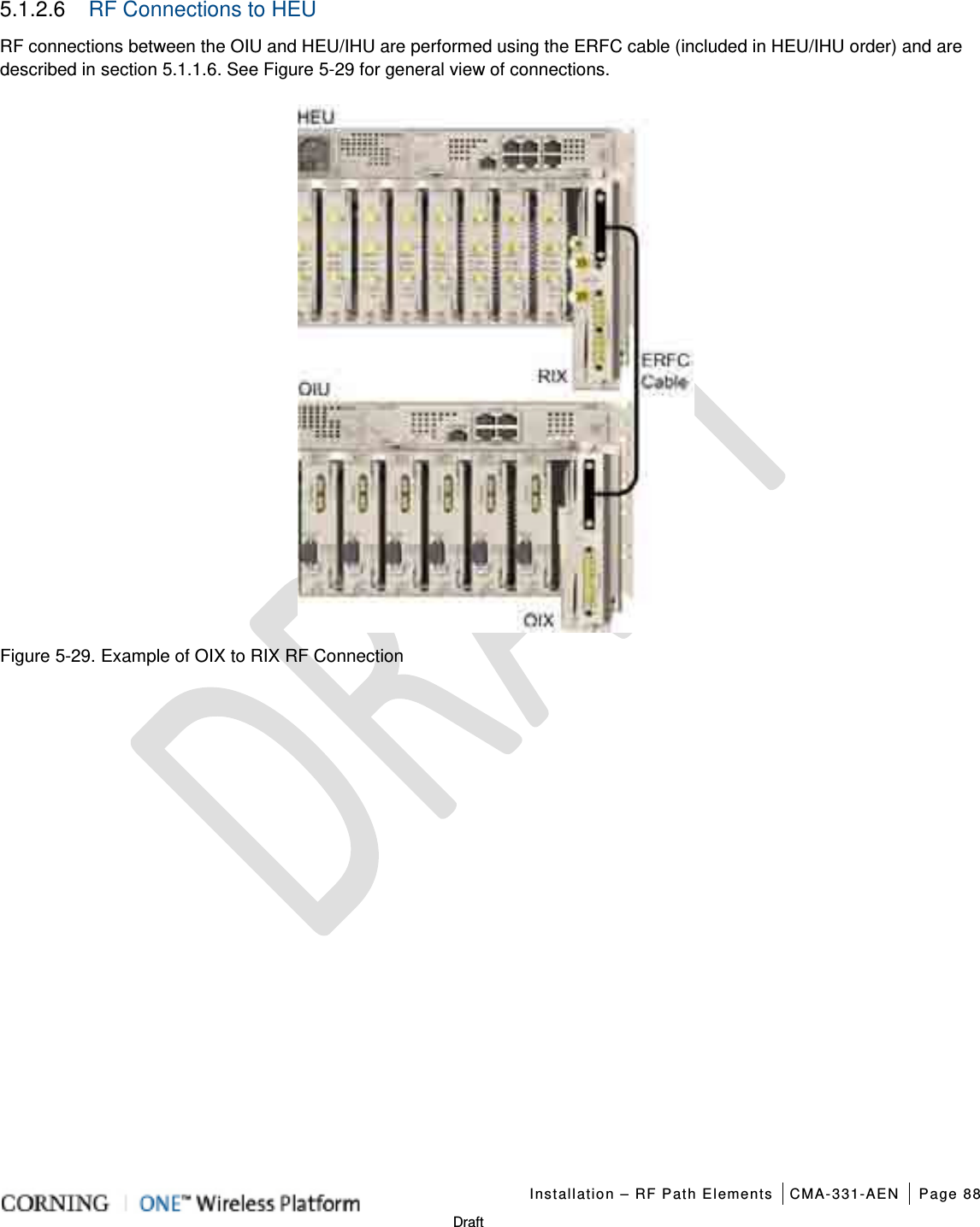
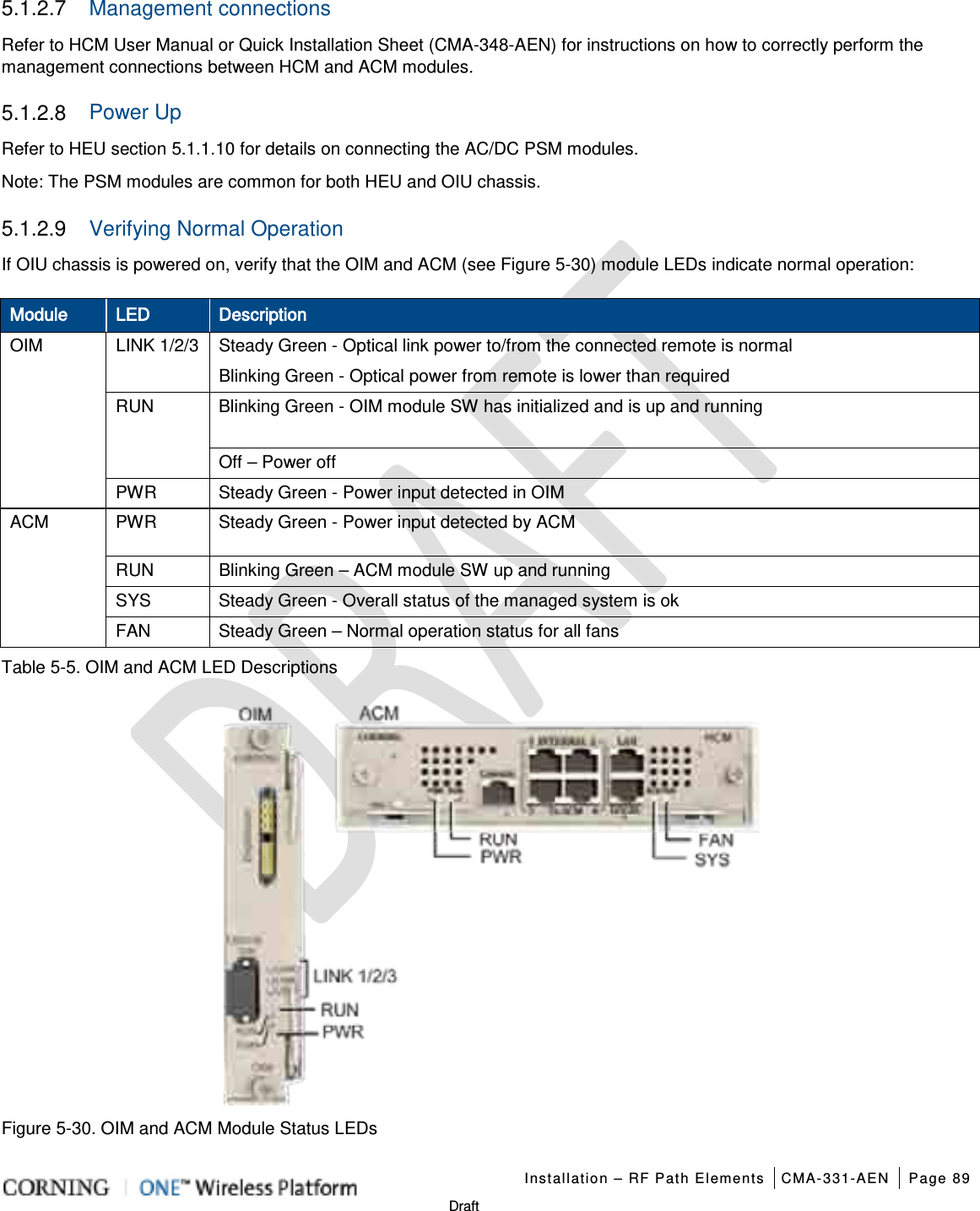
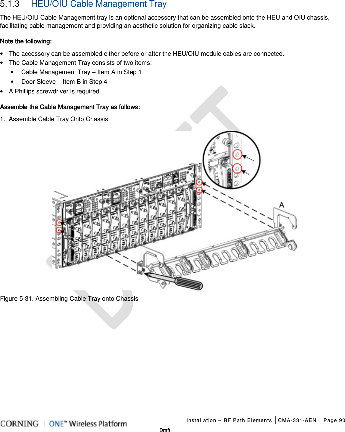
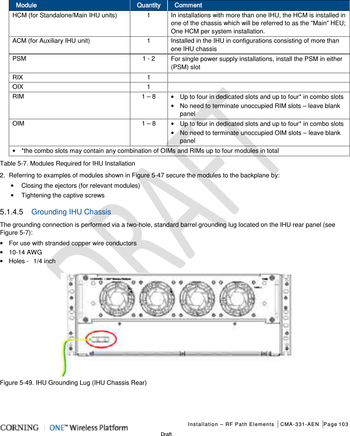
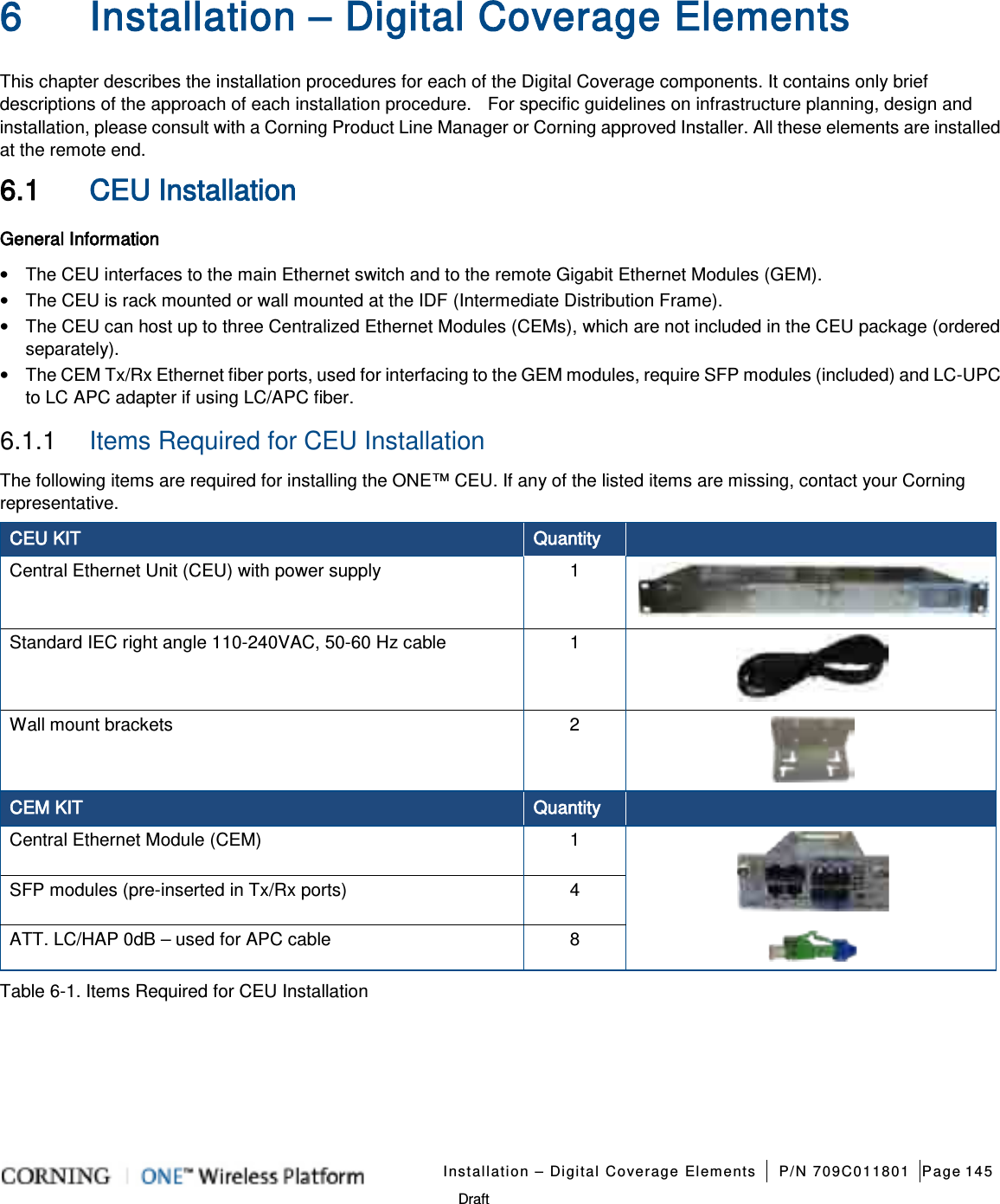
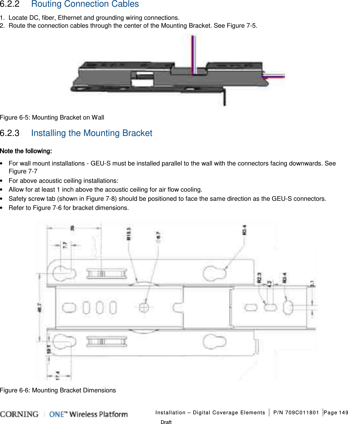
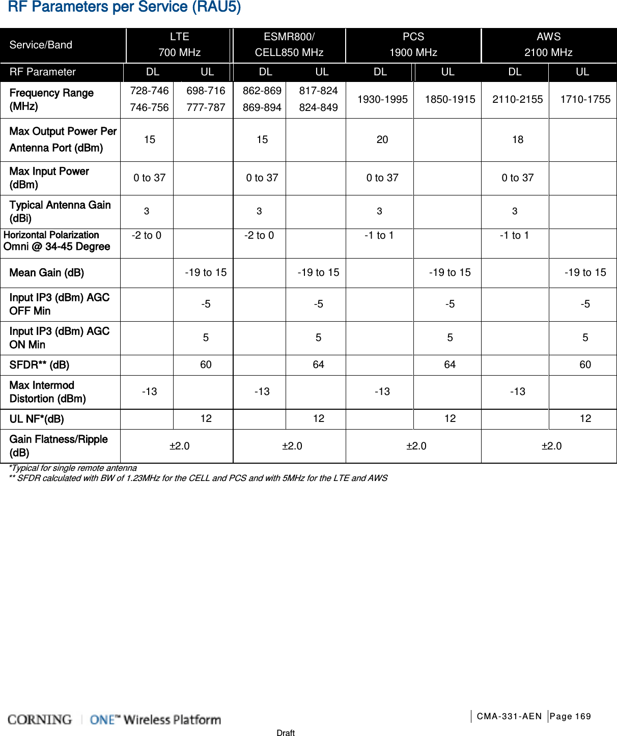
![Introduction CMA-331-AEN Page 21 Draft GEM Supporting PoE 802.3at Composite 16 AWG Tether Distance (ft.) Draw (Watts) Composite 16 AWG Tether Distance (ft.) Draw (Watts) 10 - 80 64 590 - 620 73 90 - 170 65 630 - 670 74 180 - 230 66 680 - 710 75 240 - 300 67 720 – 750 76 310 - 370 68 760 – 790 77 380 - 420 69 800 - 820 78 430 - 470 70 830 - 850 79 480 - 530 71 860 - 890 80 540 - 580 72 900 81 *Min/Max VDC = 52/57 @ 1.49 Amps, 85% efficiency Table 1-13. Remote End Distance and Power Draw for GEM w/PoE.3at 1.3.4 Dimensions and Weight of Units Table 1-14, Table 1-15 and Table 1-16 describe the physical specifications of the Corning ONE™ headend and remote end units. Unit Dimensions (H x W x D) Weight: lbs [kg] HEU 7 x 17.3 x 18.95 in (177.8 x 440 x 481.7 mm) Chassis: 37 lbs (16.8 kg) Per RIM: 1.9 lbs (0.9 kg) Per RIX: 1.54 lbs (0.7 kg) HCM: 2.2 lbs (1.0 kg) PSM: 1.98 lbs (0.9 kg) OIU 7 x 17.3 x 18.95 in [177.8 x 440 x 481.7 mm] Chassis: : 37 lbs (16.8 kg) Per OIM: 1.5 lb (0.7 kg) Per OIX: 1.54 lb (0.7 kg) ACM: 2.2 lb (1.0 kg) PSM: 1.98 lb (0.9 kg) IHU 7 x 17.3 x 15.5 in [177.8 x 440 x 394 mm] Chassis: 30 lbs (14 kg) Per RIM: 1.9 lbs (0.9 kg) Per RIX: 1.54 lbs (0.7 kg) Per OIM: 1.5 lb (0.7 kg) Per OIX: 1.54 lb (0.7 kg) ACM: 2.2 lb (1.0 kg) PSM: 1.98 lb (0.9 kg) Table 1-14. RF Path Headend Units](https://usermanual.wiki/Corning-Optical-Communication/1RAU5/User-Guide-2485046-Page-21.png)
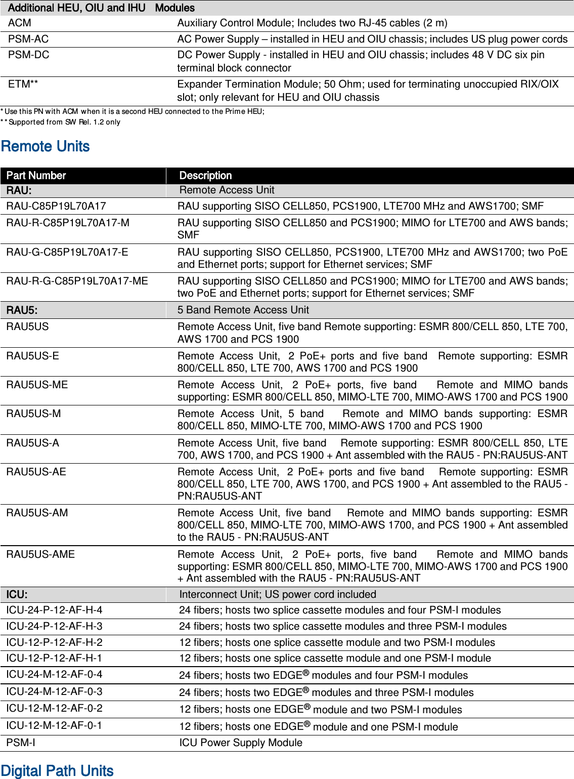
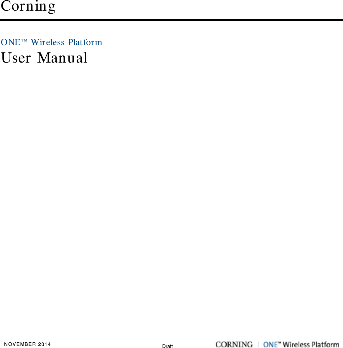
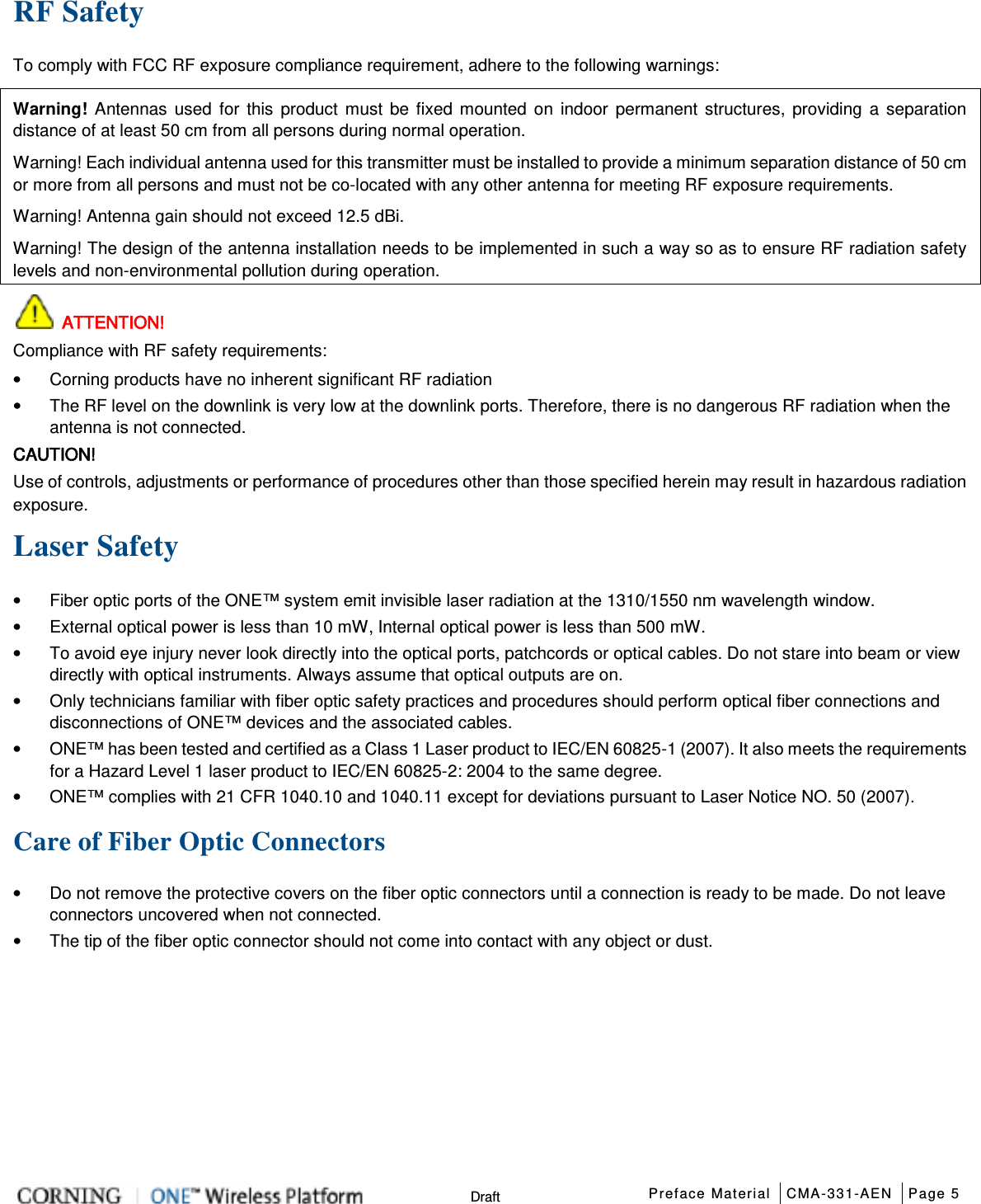
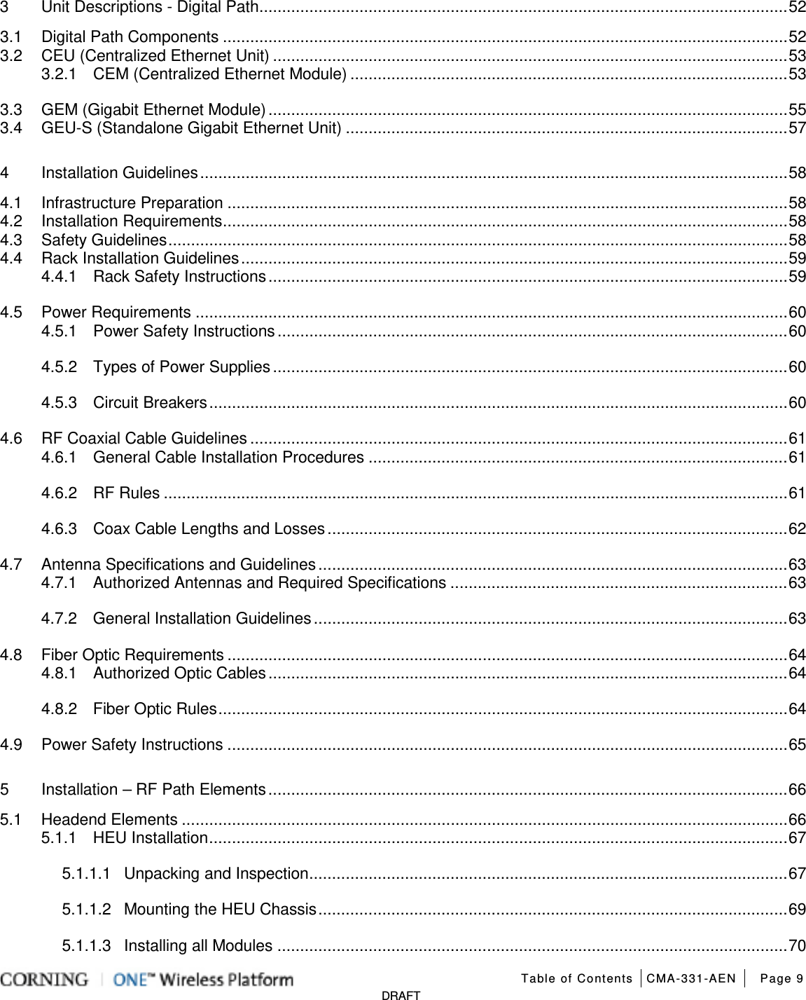
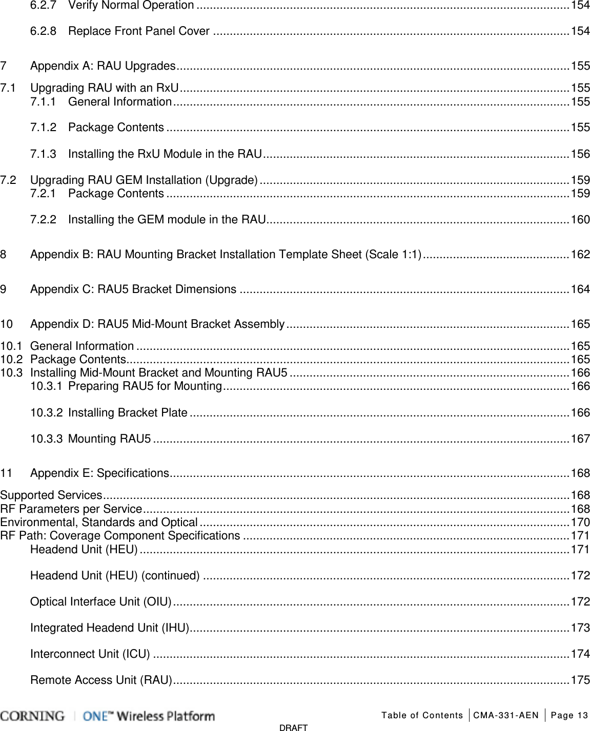
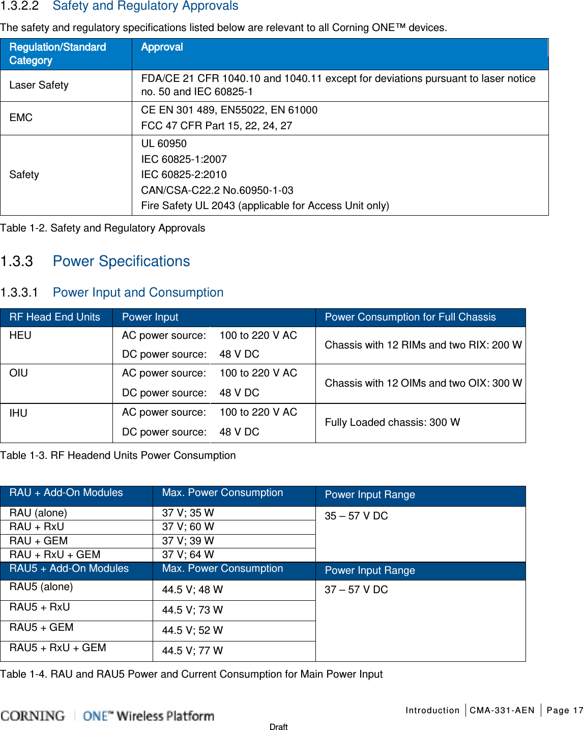
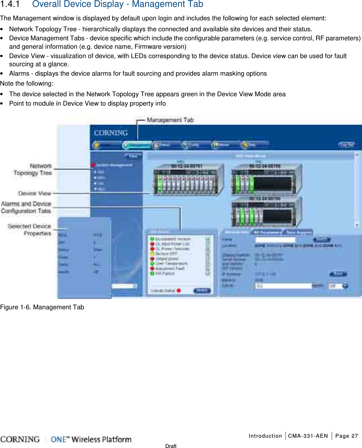
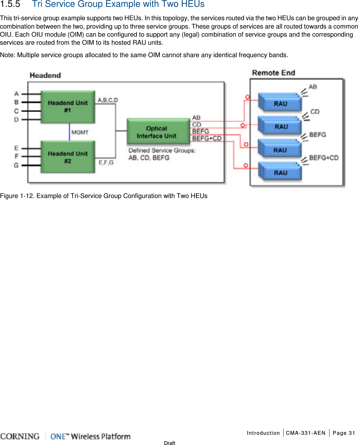
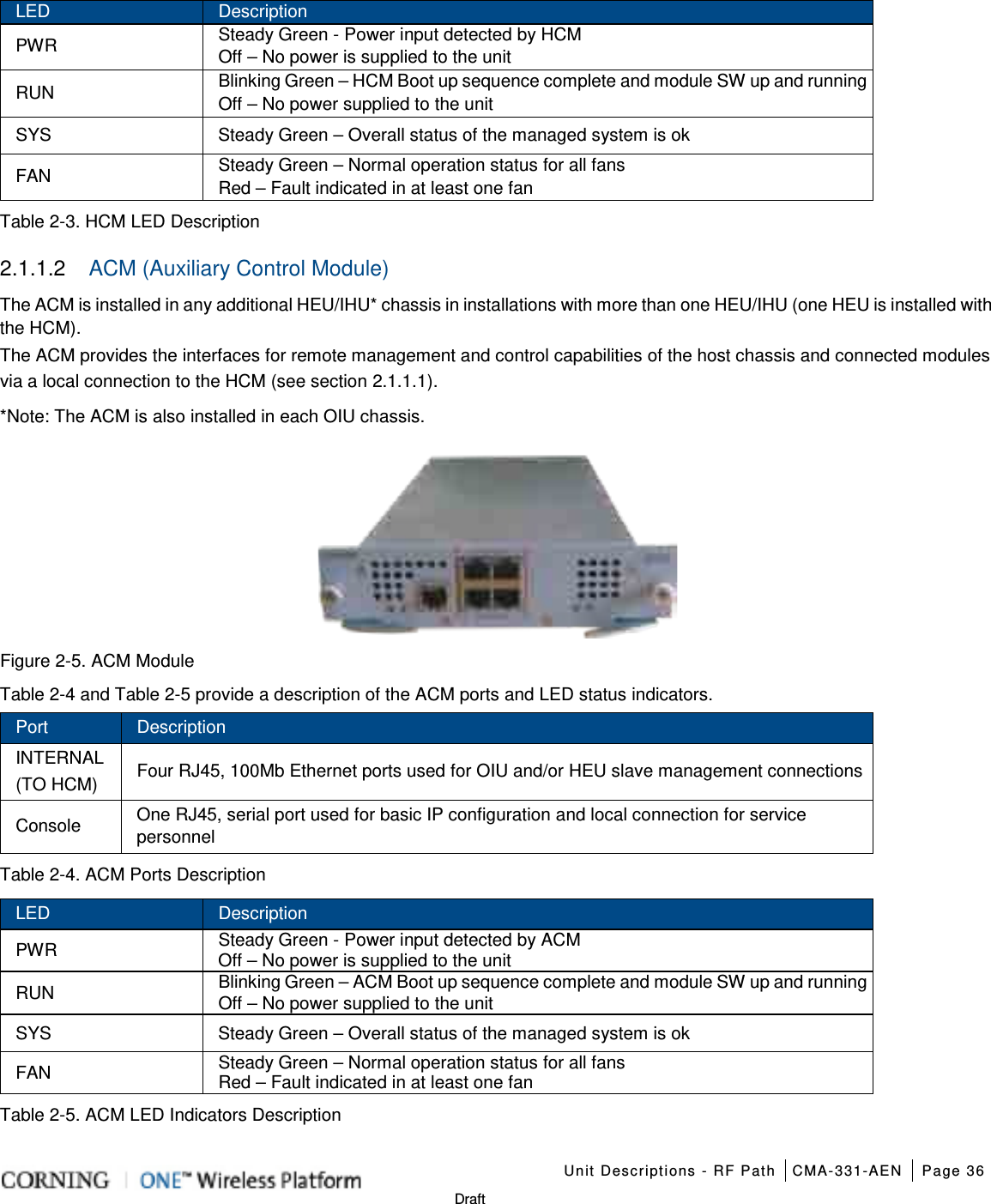
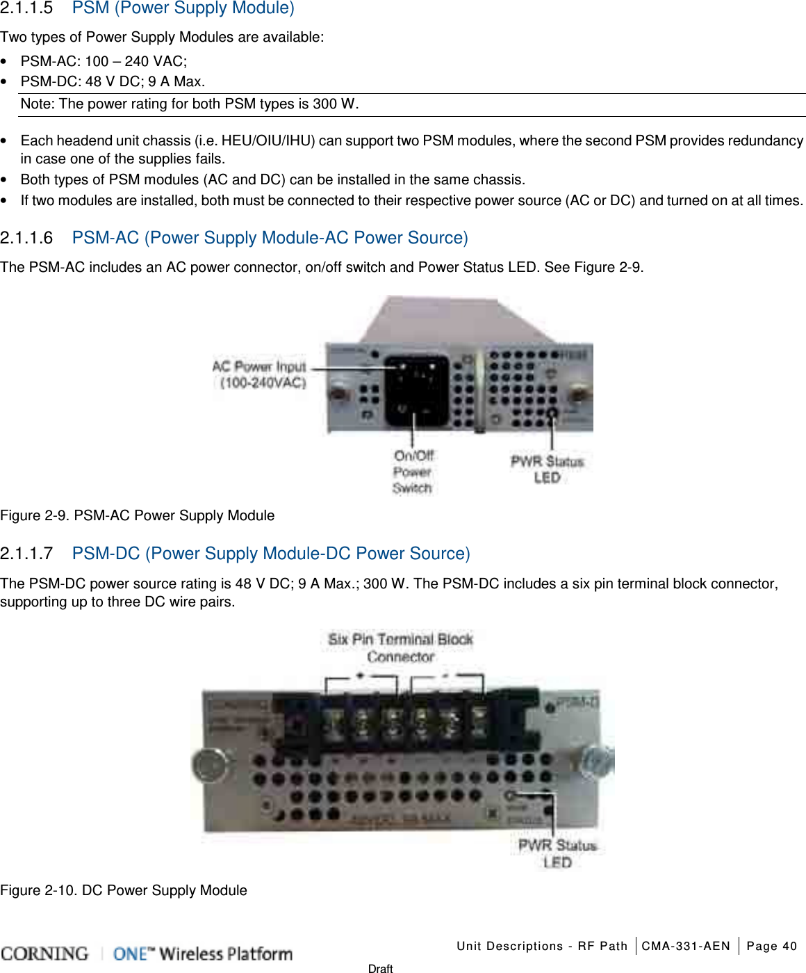
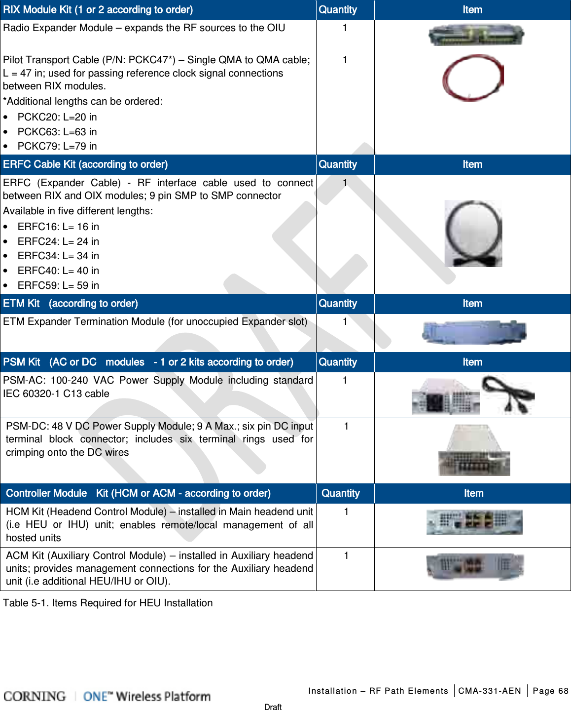
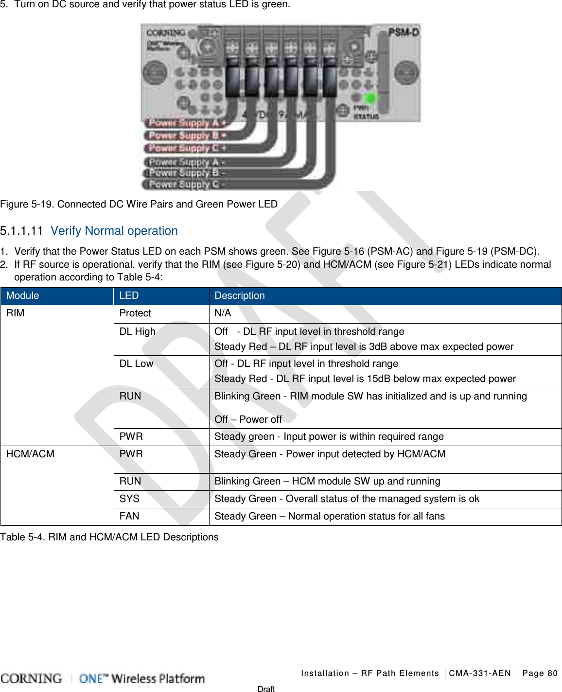
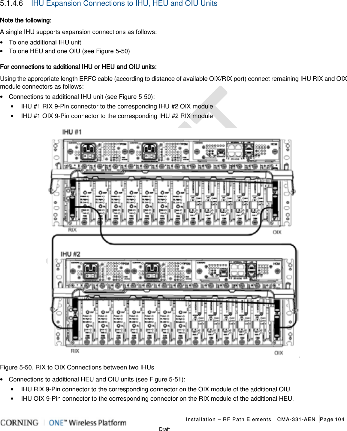
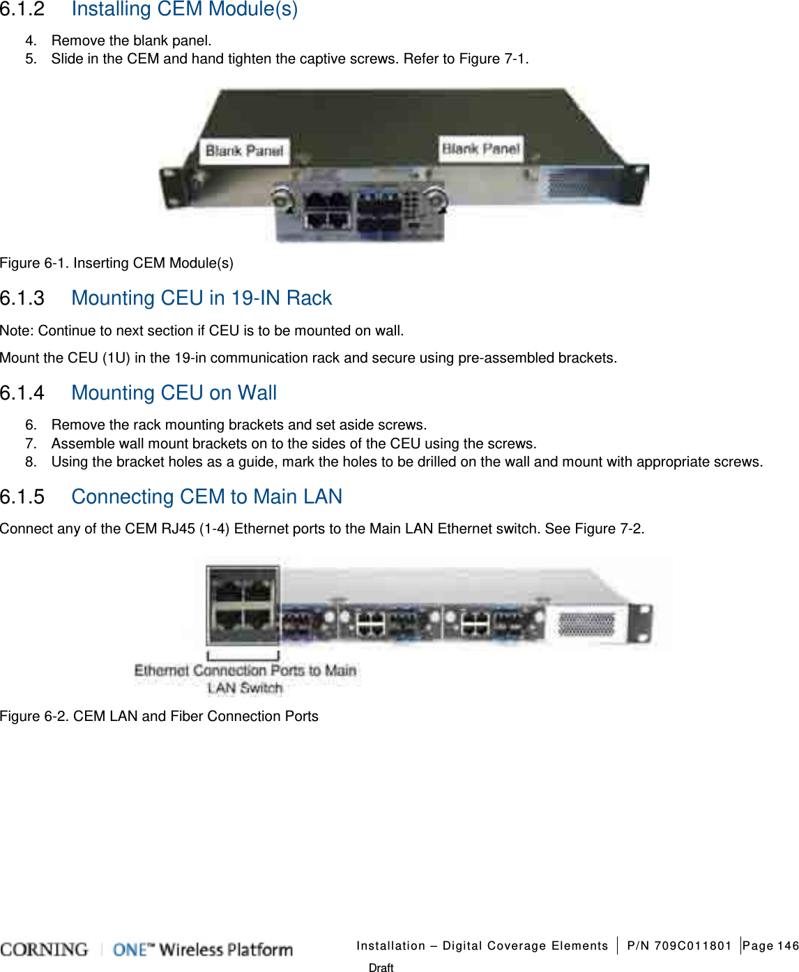
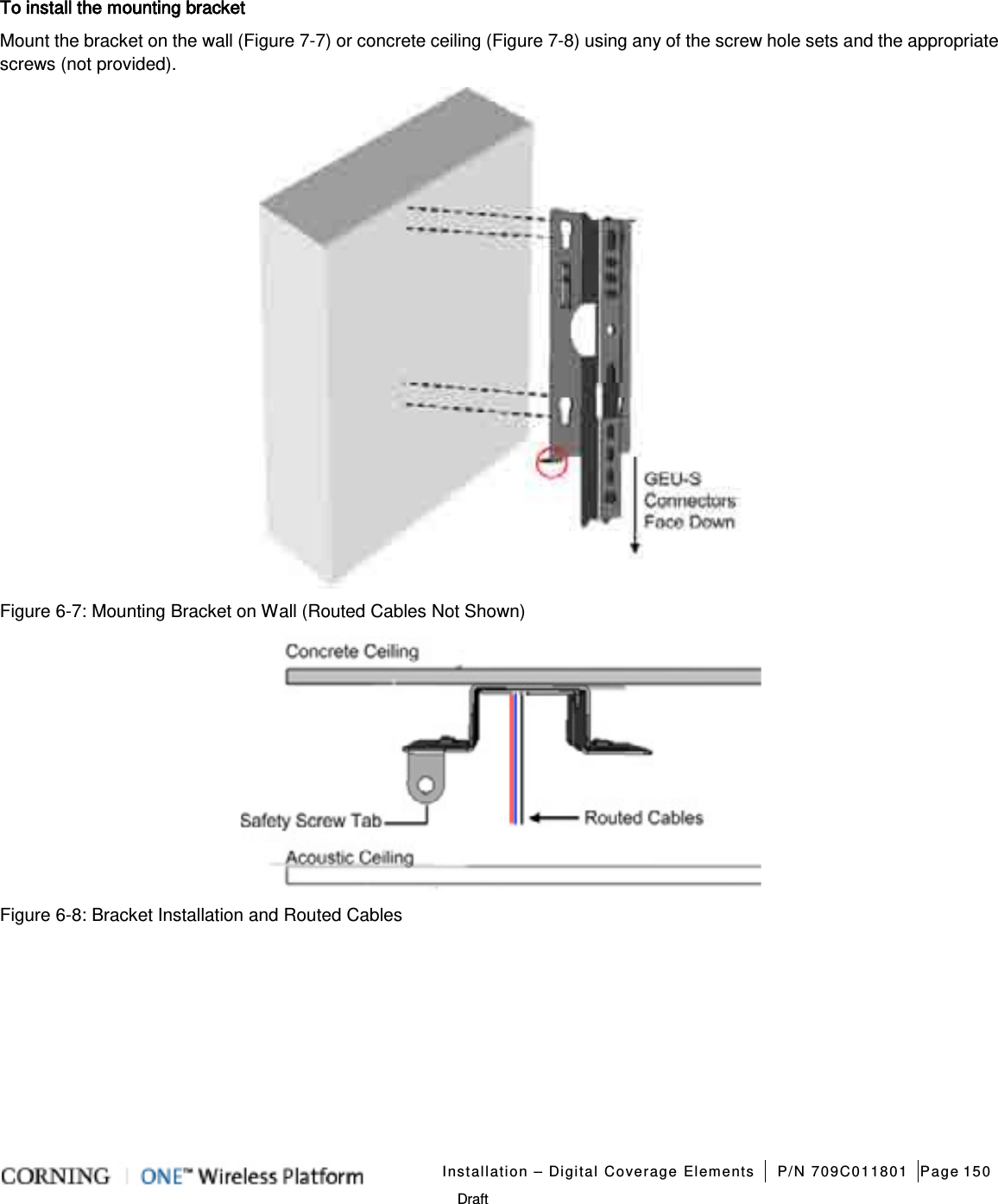
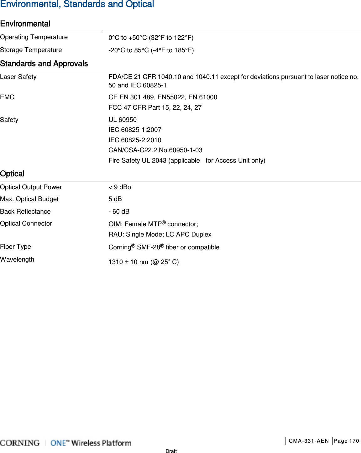
![Introduction CMA-331-AEN Page 22 Draft Unit Dimensions (H x W x D) Weight: lbs [kg] ICU 1.74 x 17 x 19.2 in (44.4 x 431.8 x 11.96 mm) 5.5 lb (2.5 kg) – without PSM RAU (including mounting bracket) 13.1 x 13.1 x 4 in (332.7 x 332.7 x 101.6 mm) RAU only = 7.93 lb (3.6 kg); RAU + RxU + GEM = 12.2 lb (5.5 kg) RAU5 (including mounting bracket) 5.25 x 13.1 x 13.1 in (133.35 x 332.74 x 332.74 mm) RAU5 only: 10 lbs (4.5 kg) RAU5 + RXU + GEM: 14.39 lbs (6.5 kg) Table 1-15. RF Path Remote Units Unit Dimensions (H x W x D) Weight: lbs [kg] CEU: CEU 1.71 x 17 x 8.5 in (43.65 x 431.8 x 216 mm) (with mounting ears: W = 19 in/482.8 mm) 7.55 lb (3.4 kg) CEM 1.41 x 3.94 x 7.68 in (36 x 100.14 x 195.14 mm) 1.44 lb (0.65 kg) GEM 1.28 x 3.79 x 5.95 in (32.7 x 96.3 x 151.3 mm) 1.1 lb (0.5 kg) GEU-S 5.01 x 10.51 x 3.26 in (including mounting bracket) (127.5 x 267 x 83 mm) 2.64 lb (1.2 kg) Table 1-16. Digital Path Units 1.3.5 Optical Specifications Parameter Specification Optical Output Power < 9 dBo Max. Optical Budget 5 dB Optical Connector OIM: MTP® connector RAU: LC APC SM Fiber Type Corning® SMF-28® or Compatible Wavelength 1310±10 nm (Standard) Table 1-17. Optical Specifications](https://usermanual.wiki/Corning-Optical-Communication/1RAU5/User-Guide-2485046-Page-22.png)
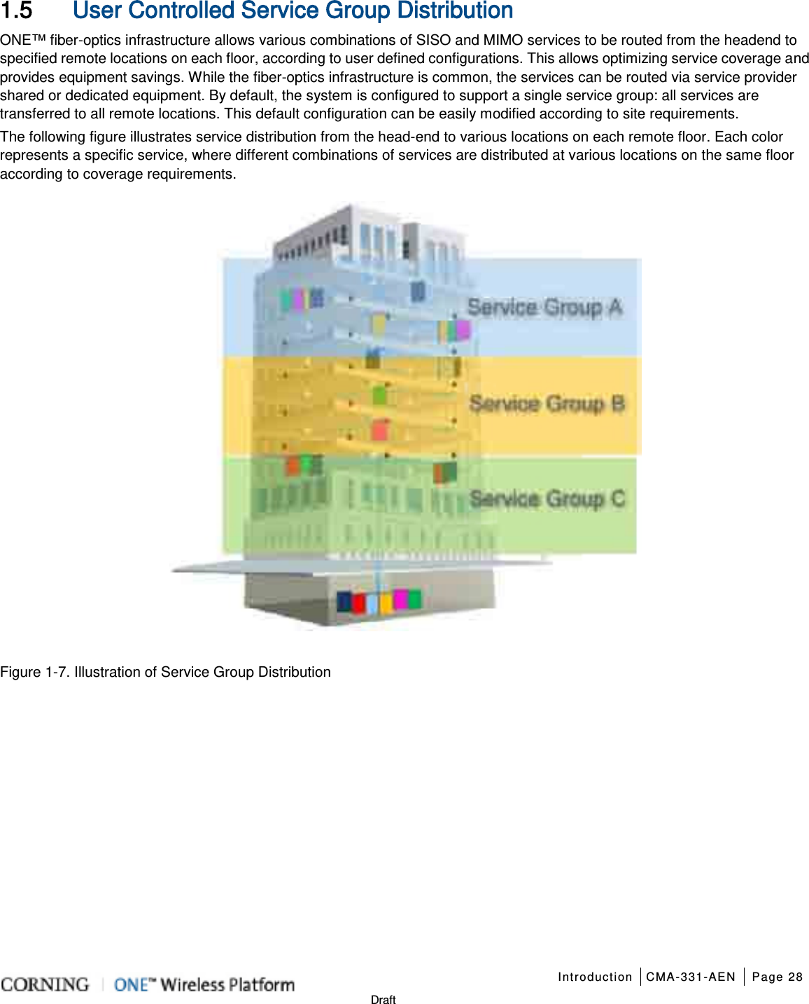
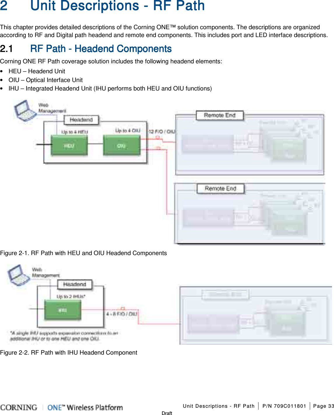
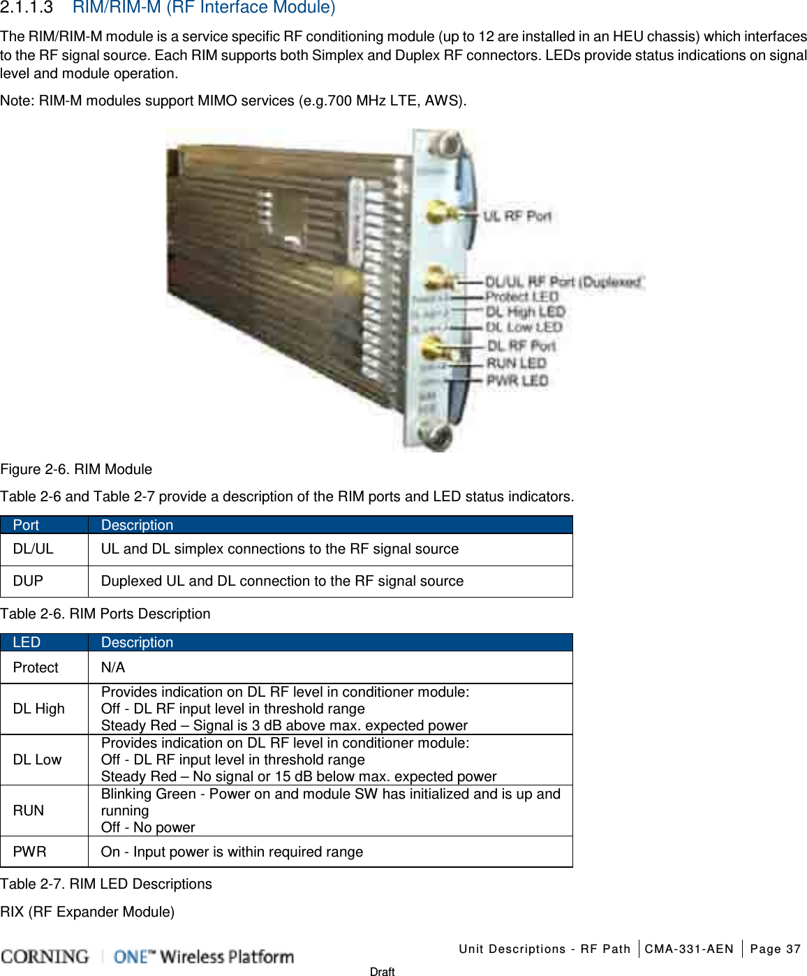
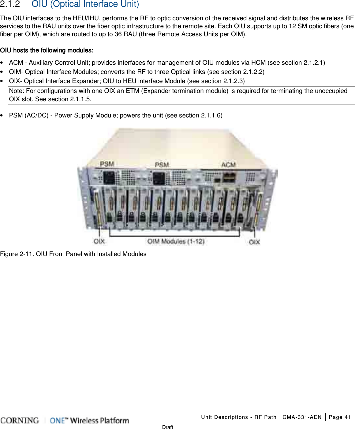
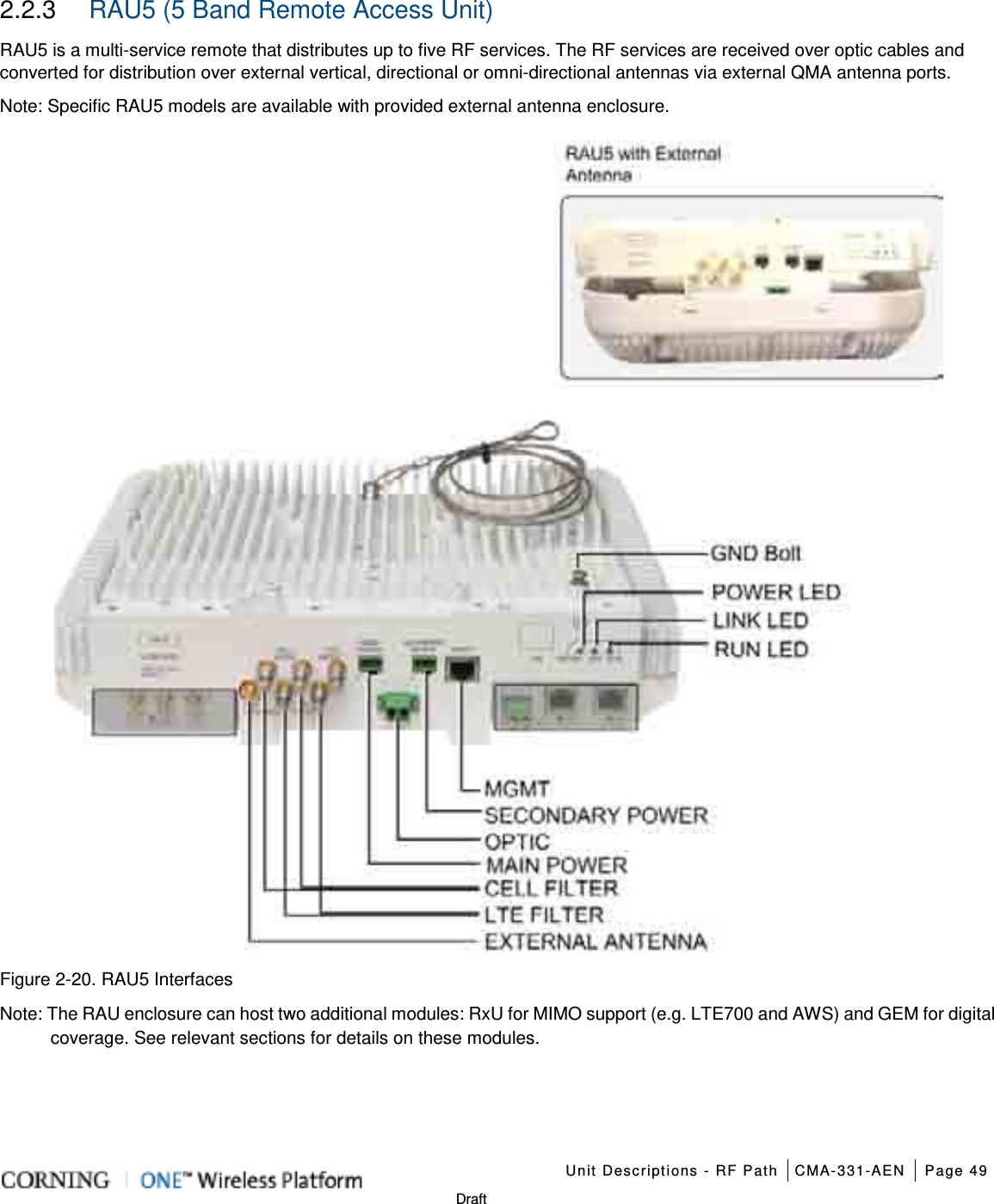
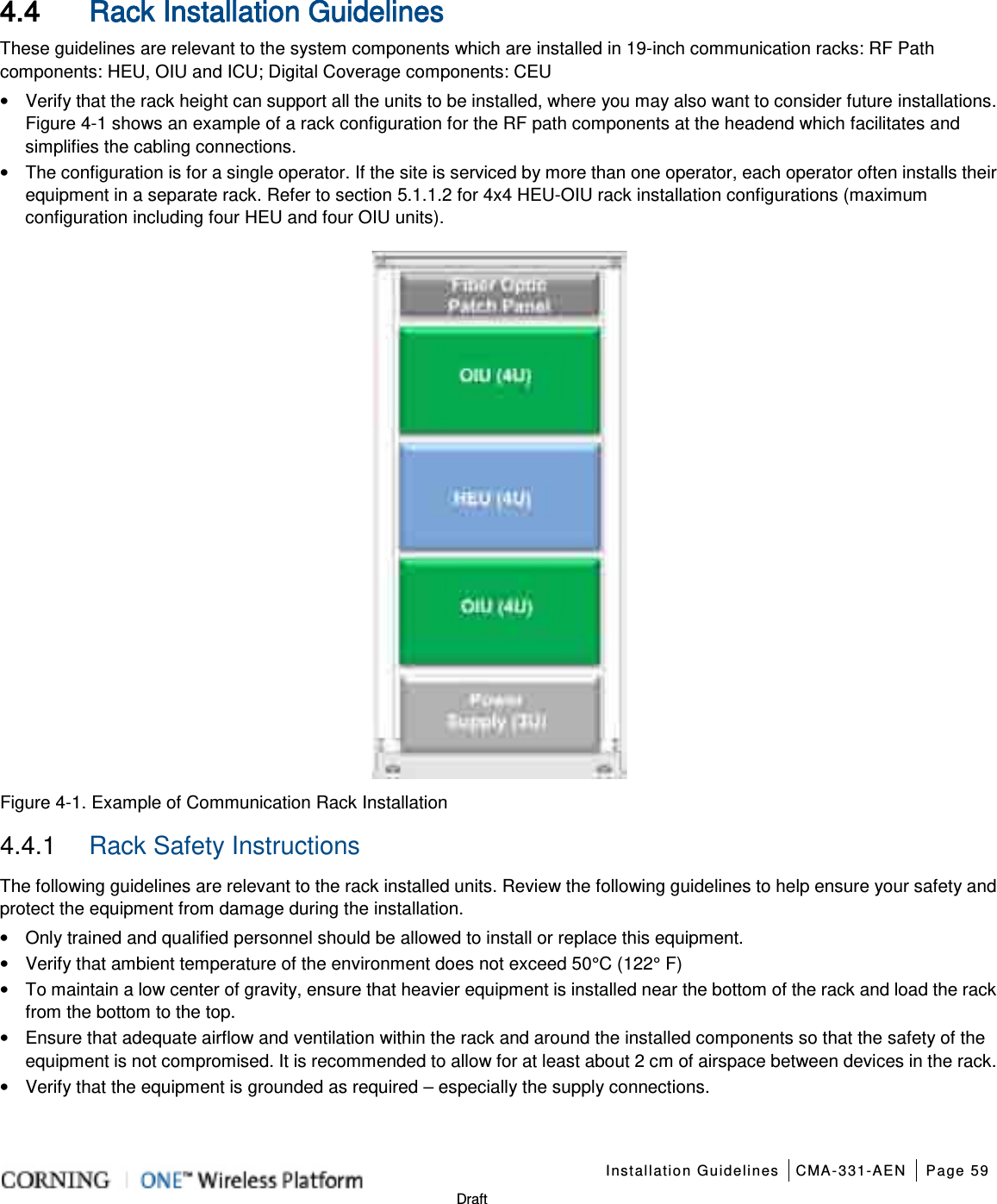
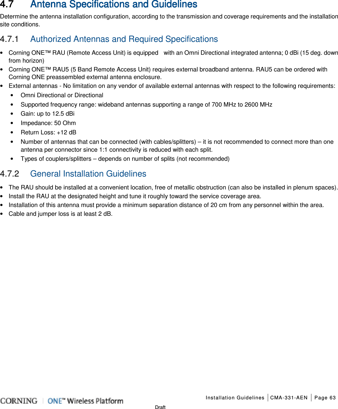
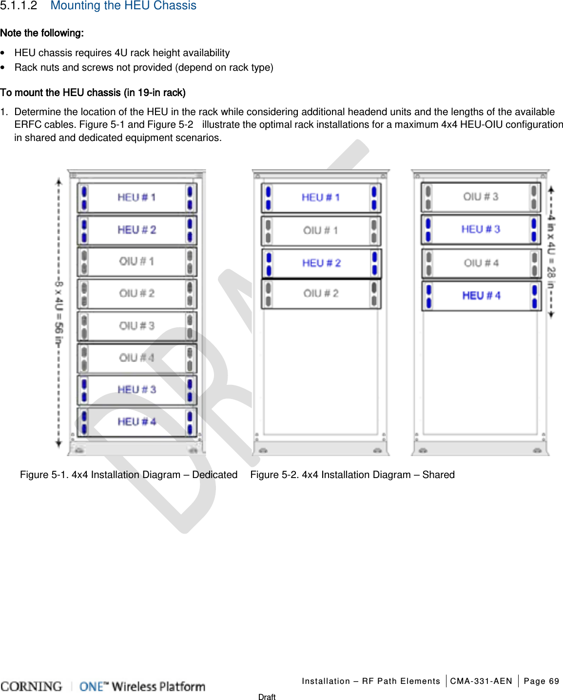
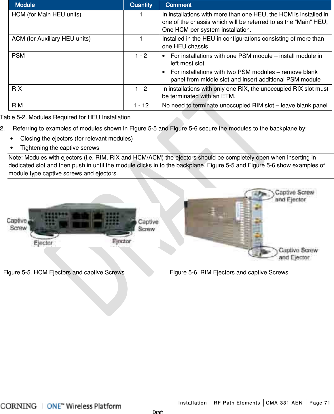
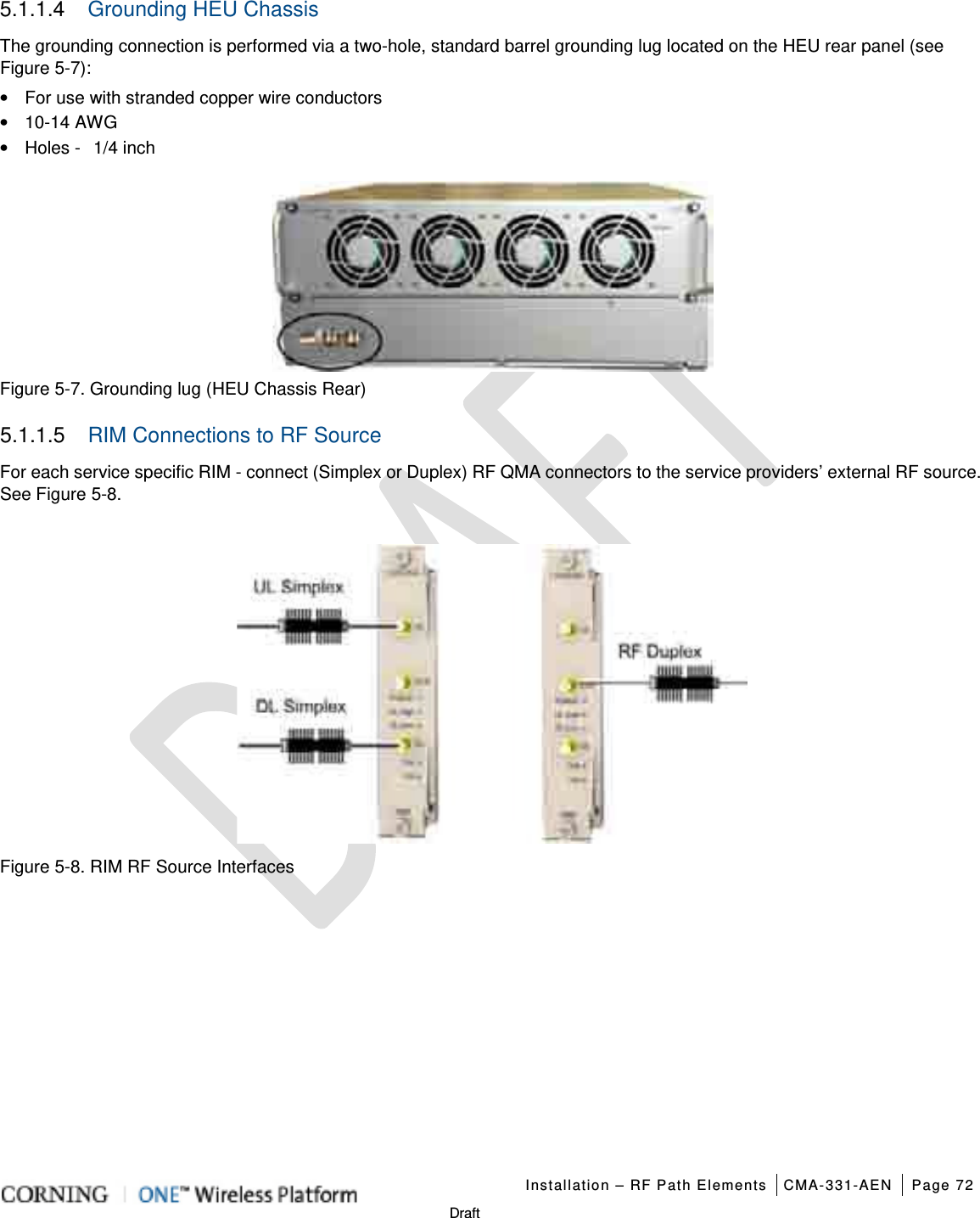
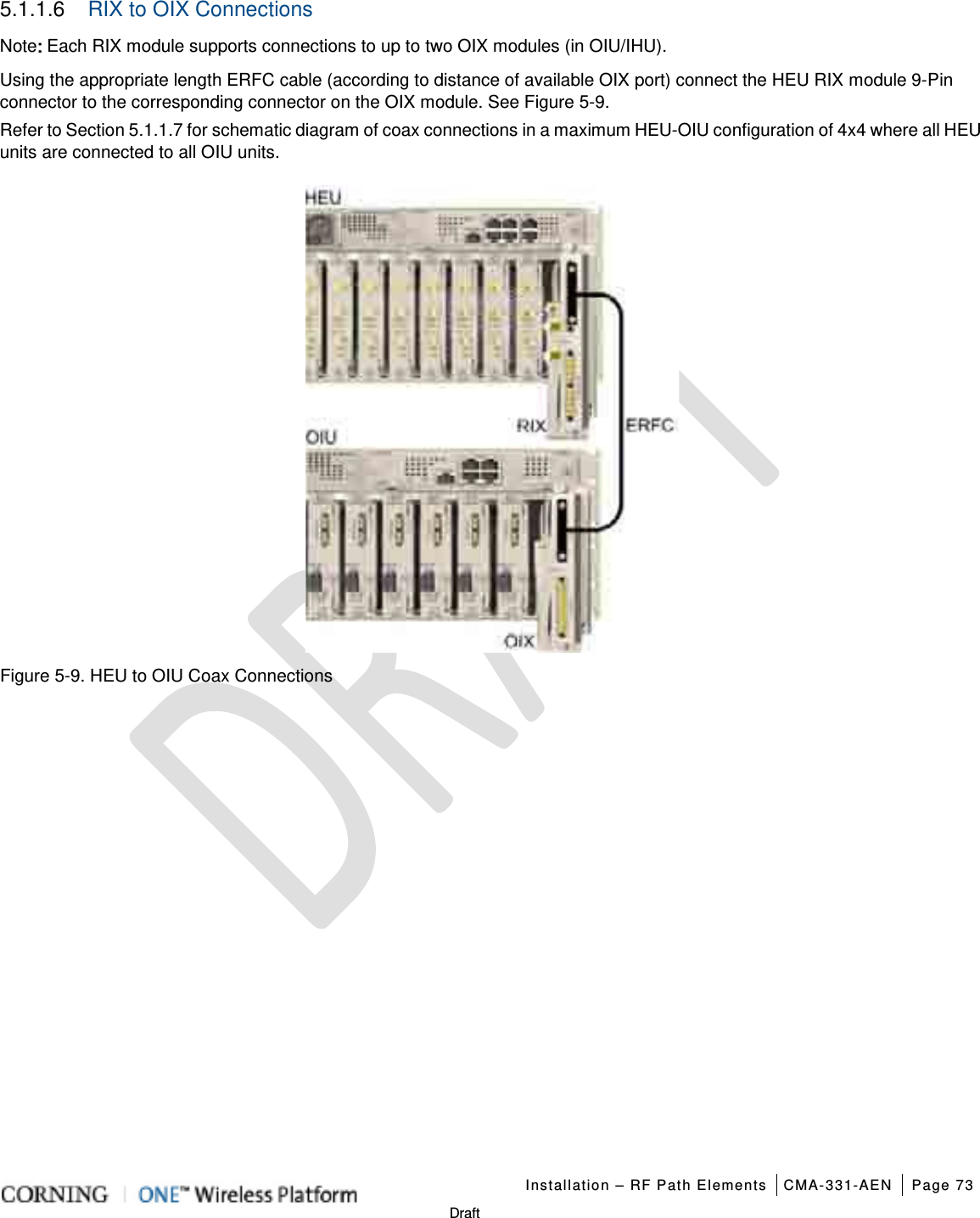
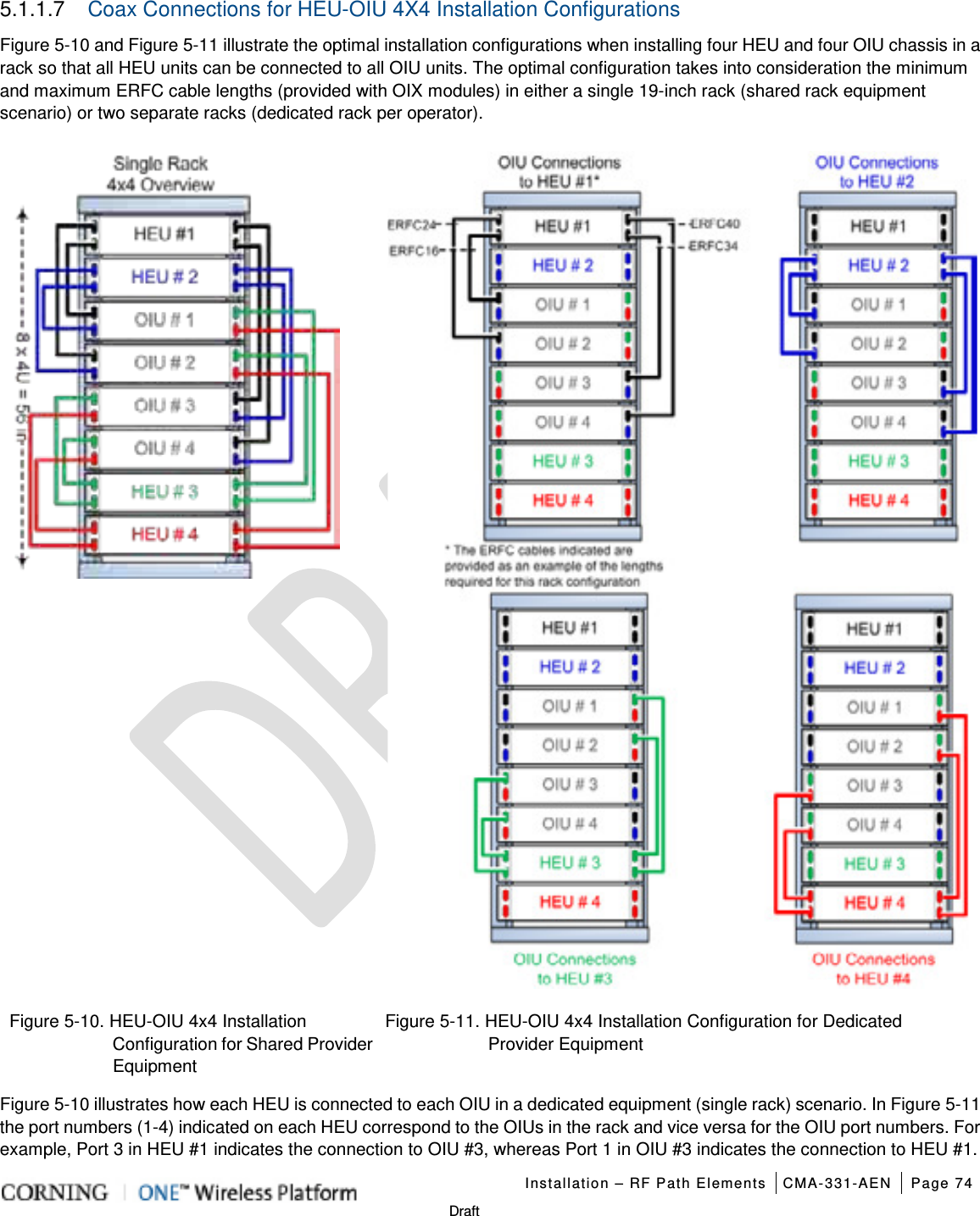
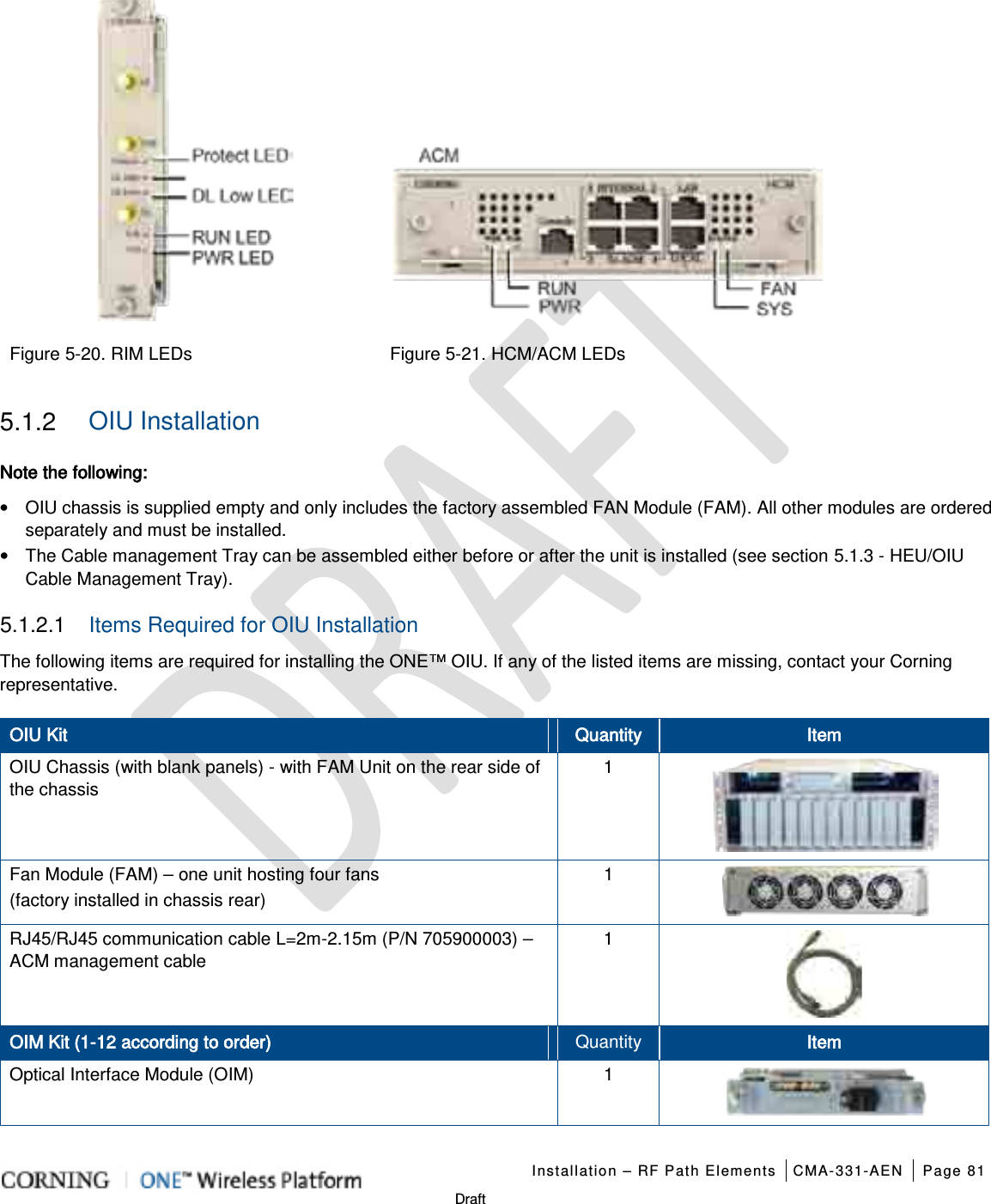
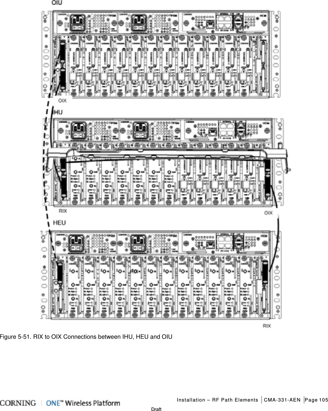
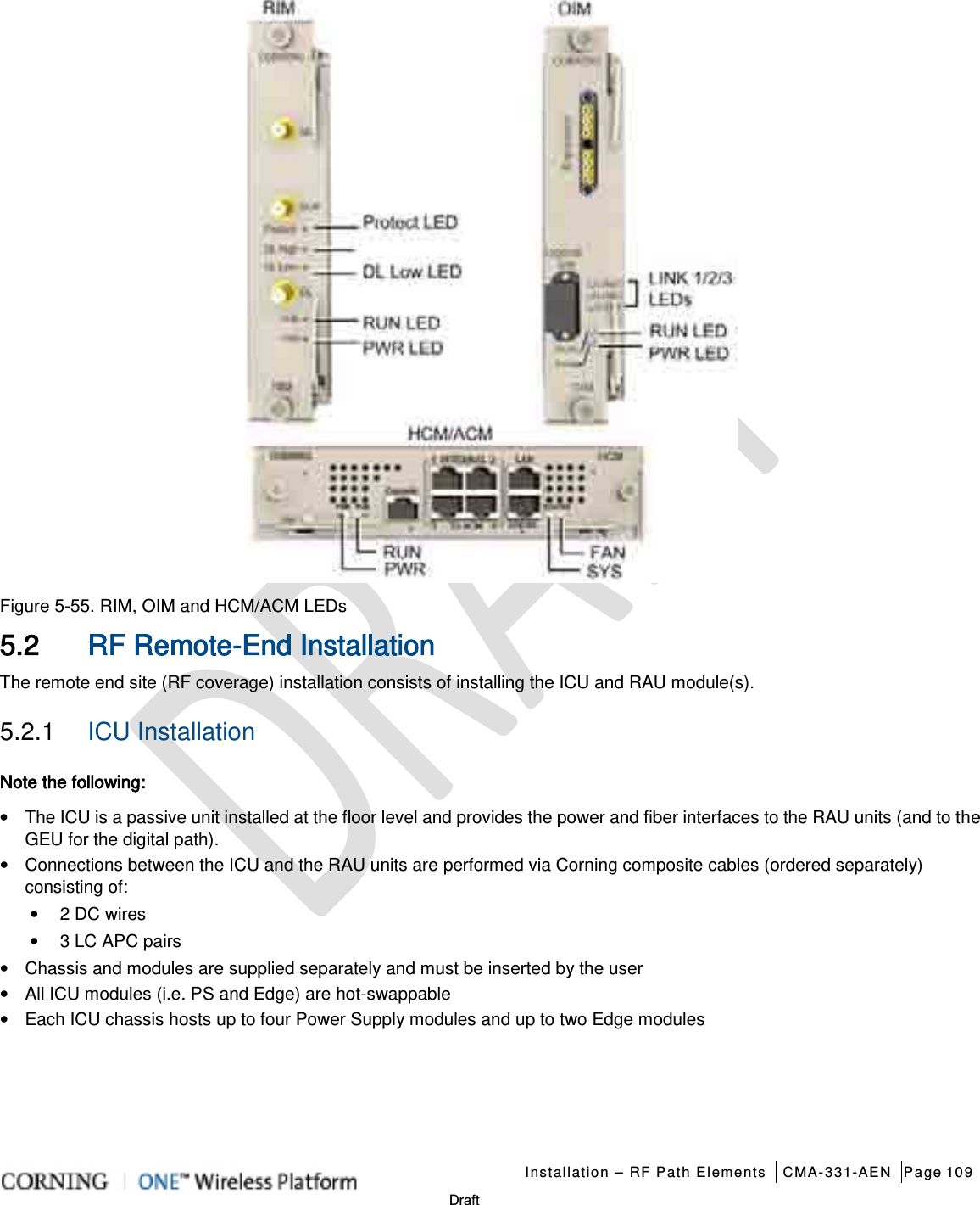
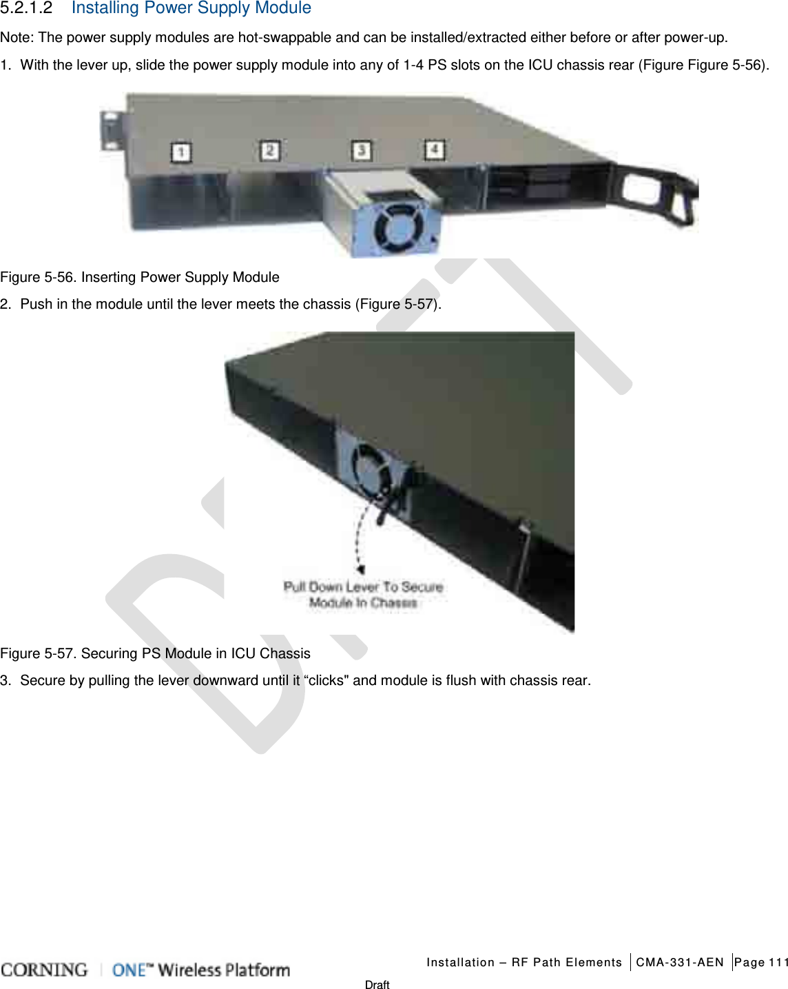
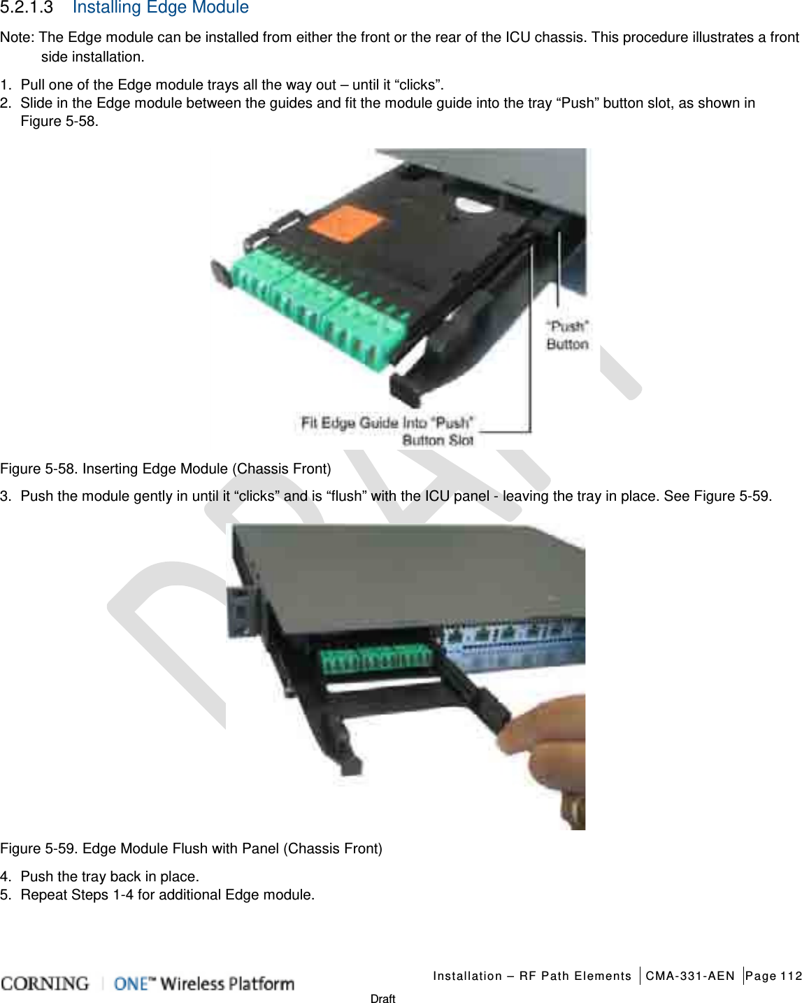
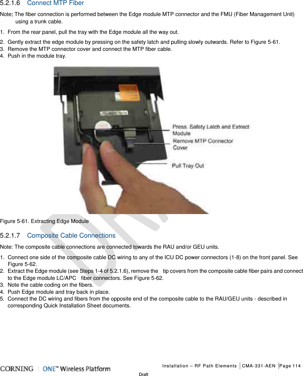
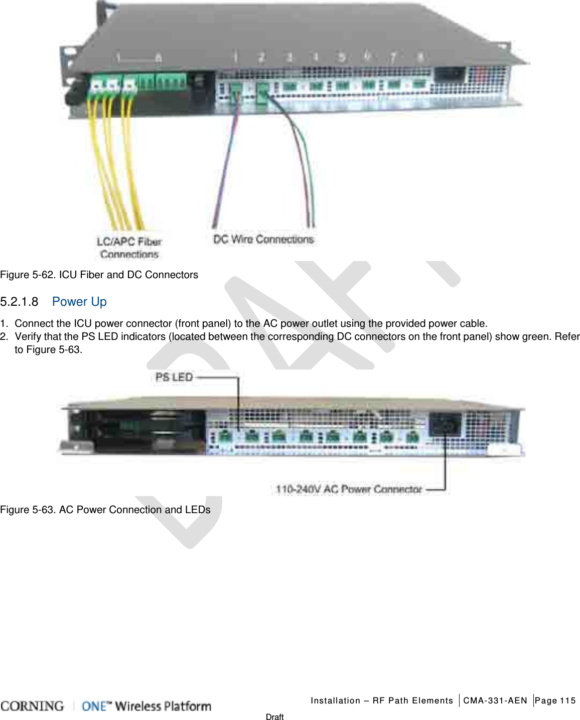
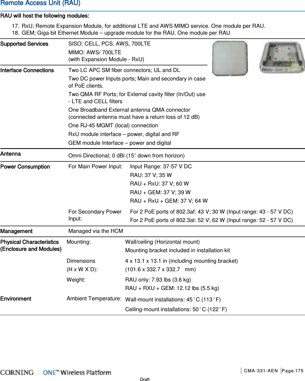
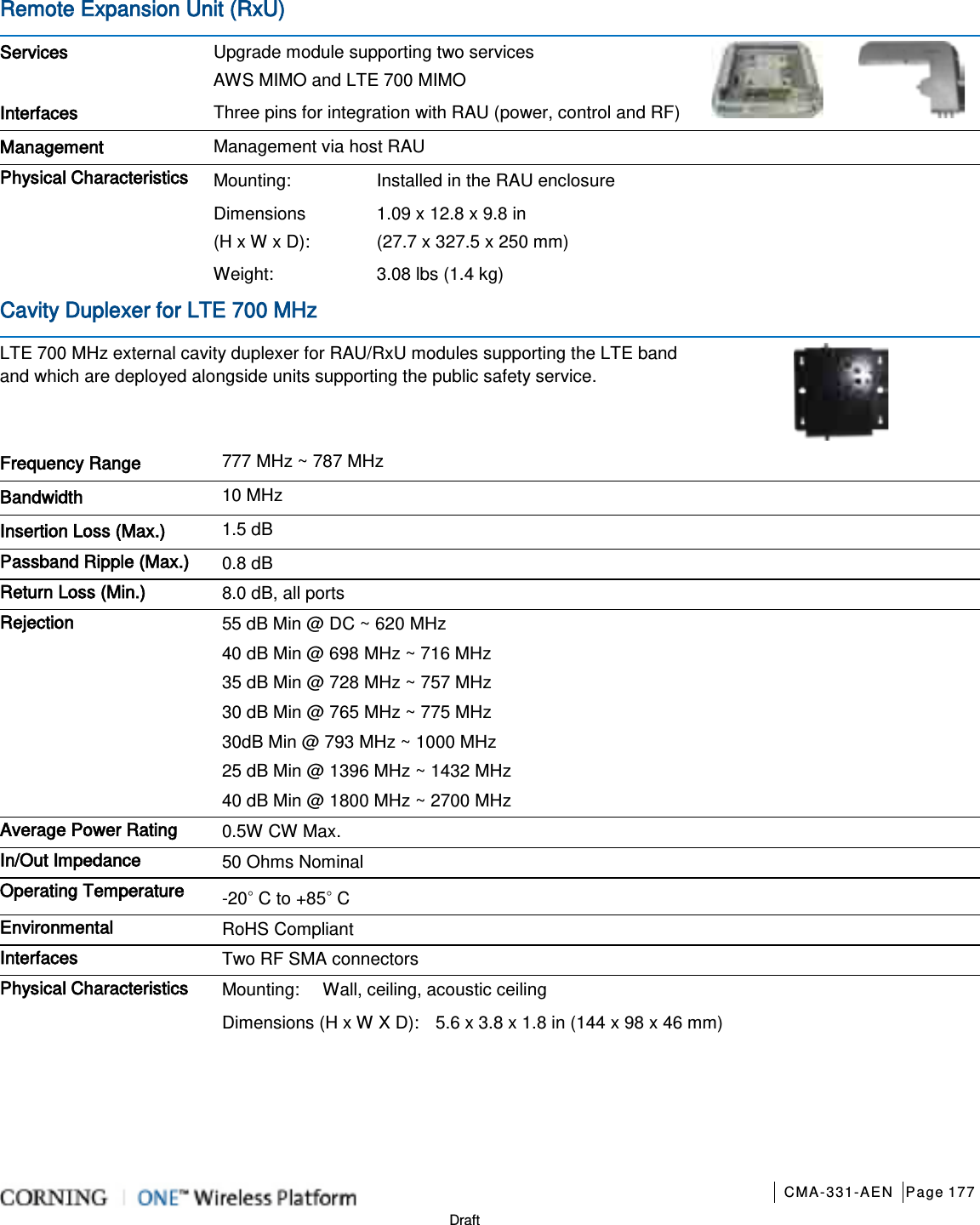
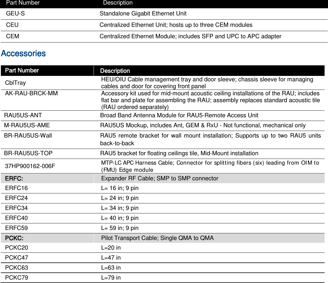
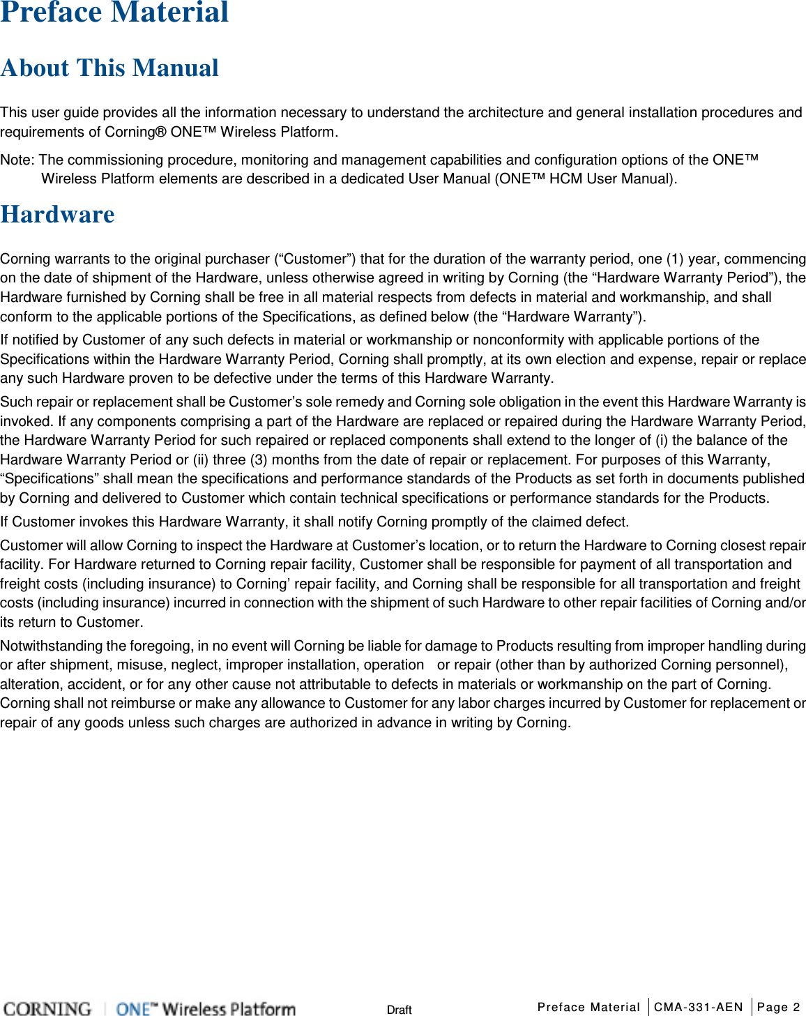
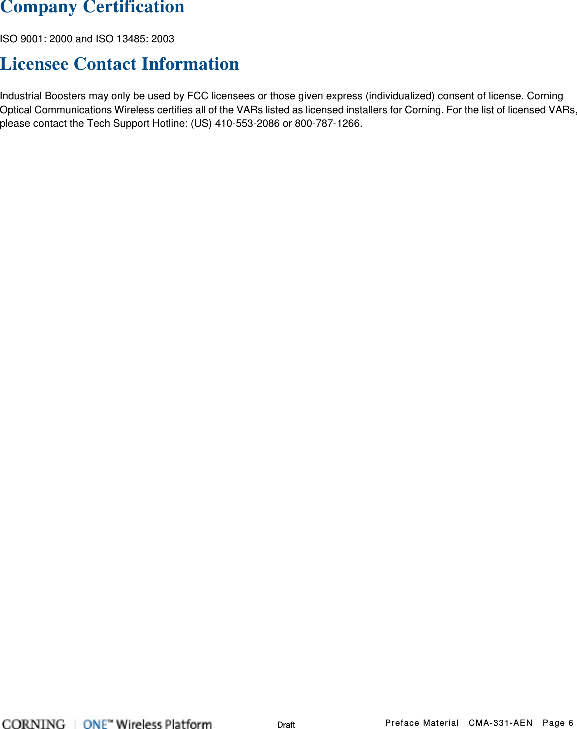
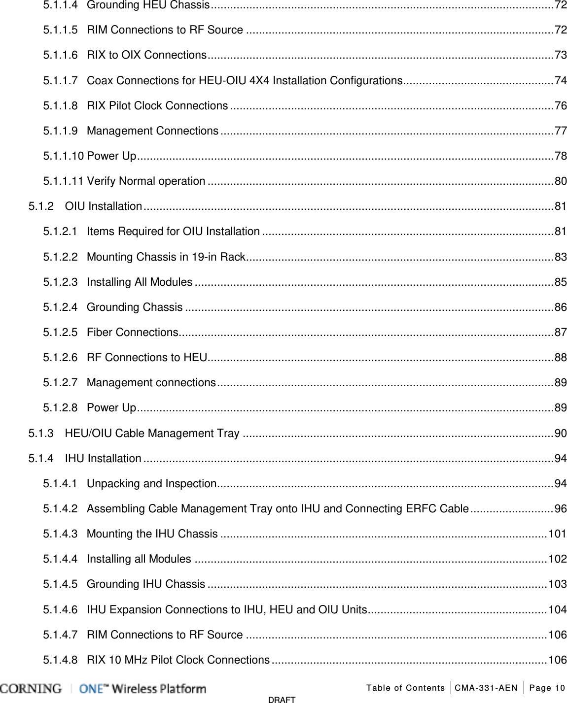
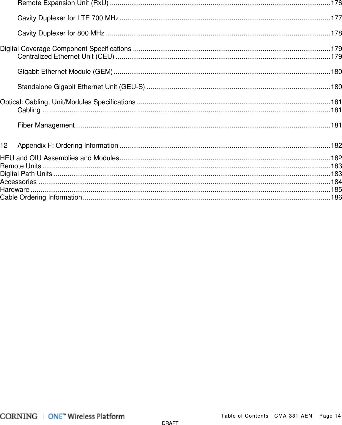
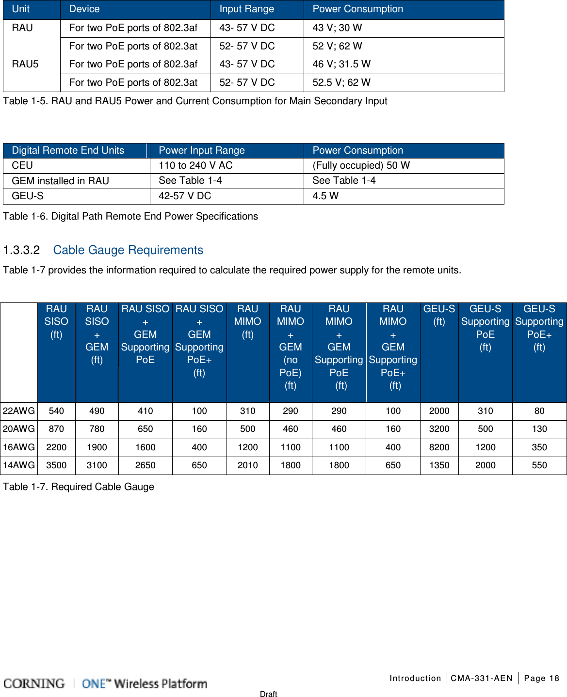
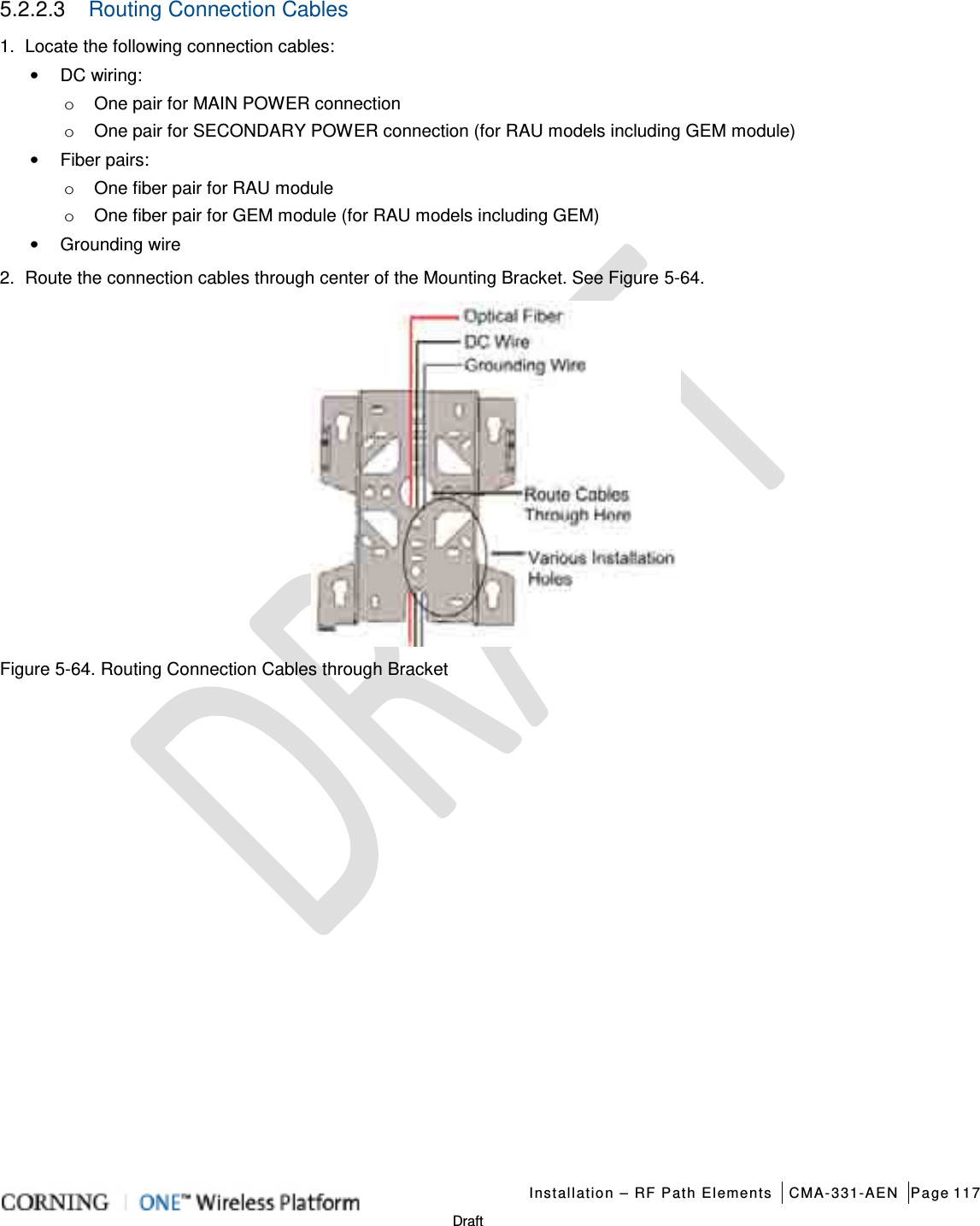
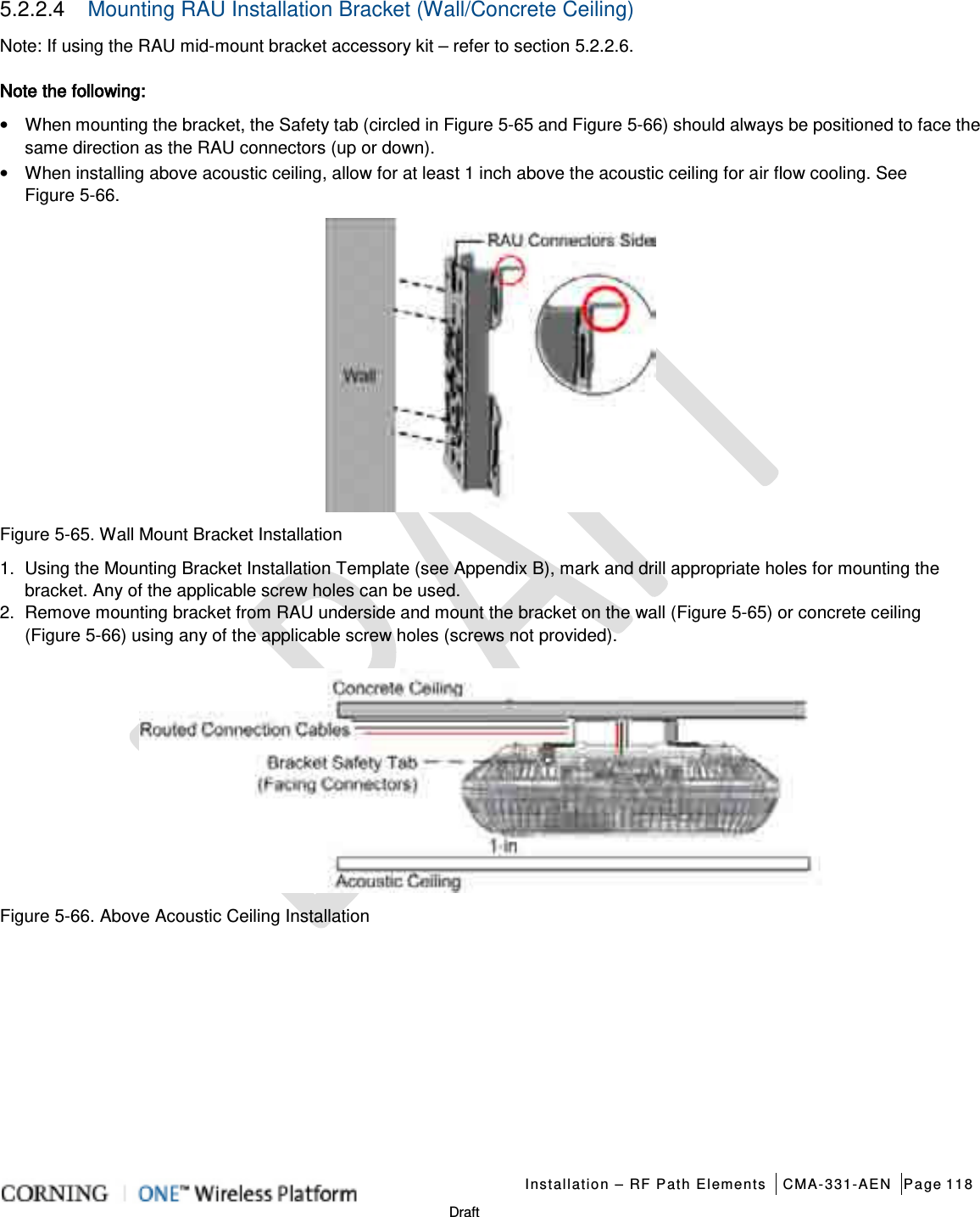
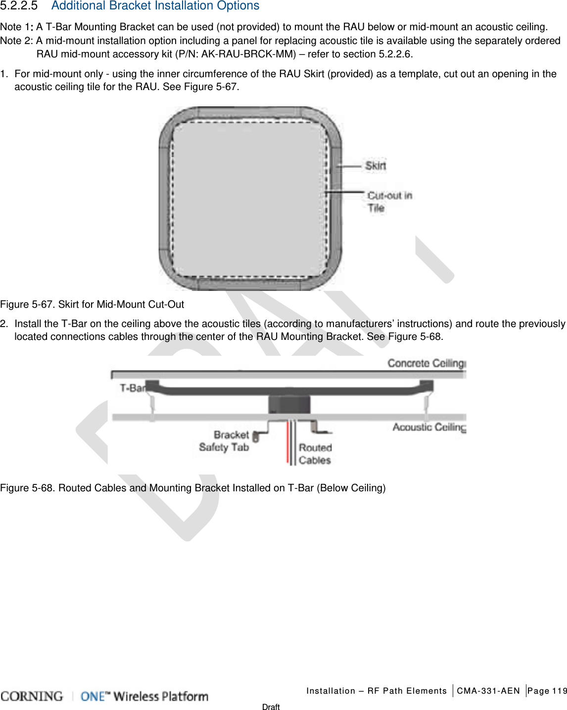
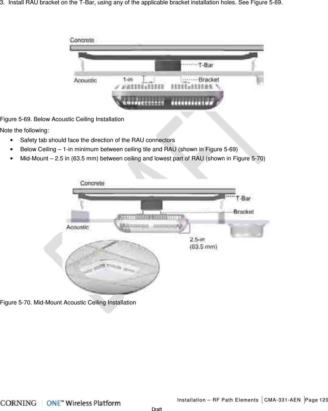
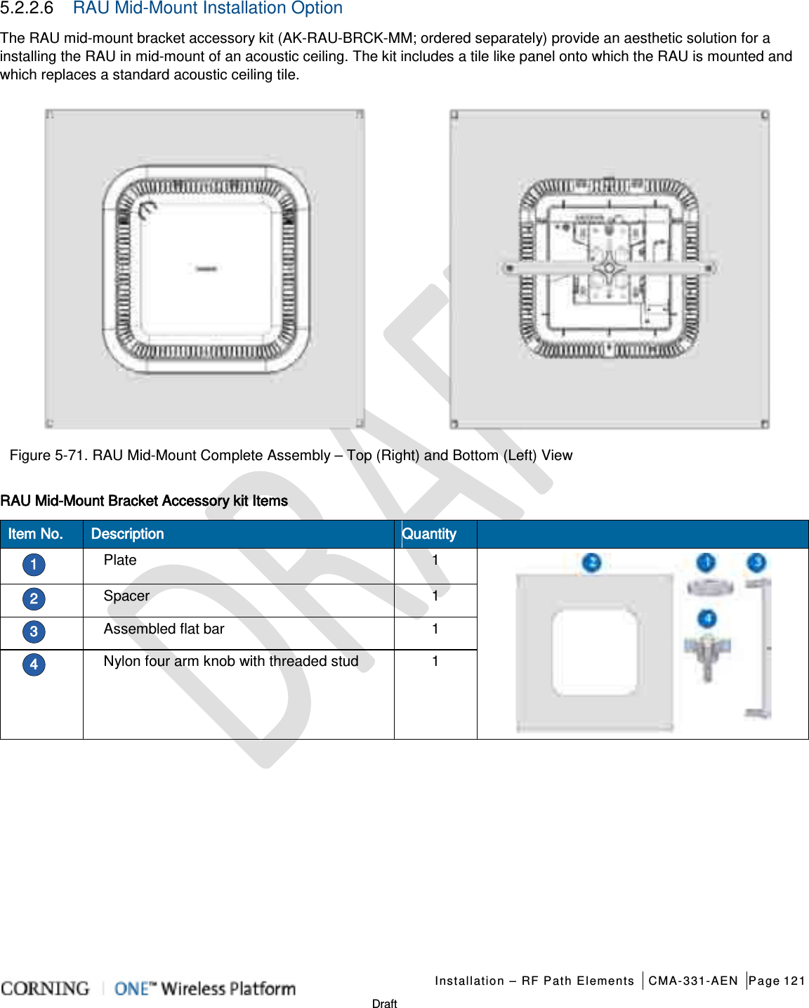
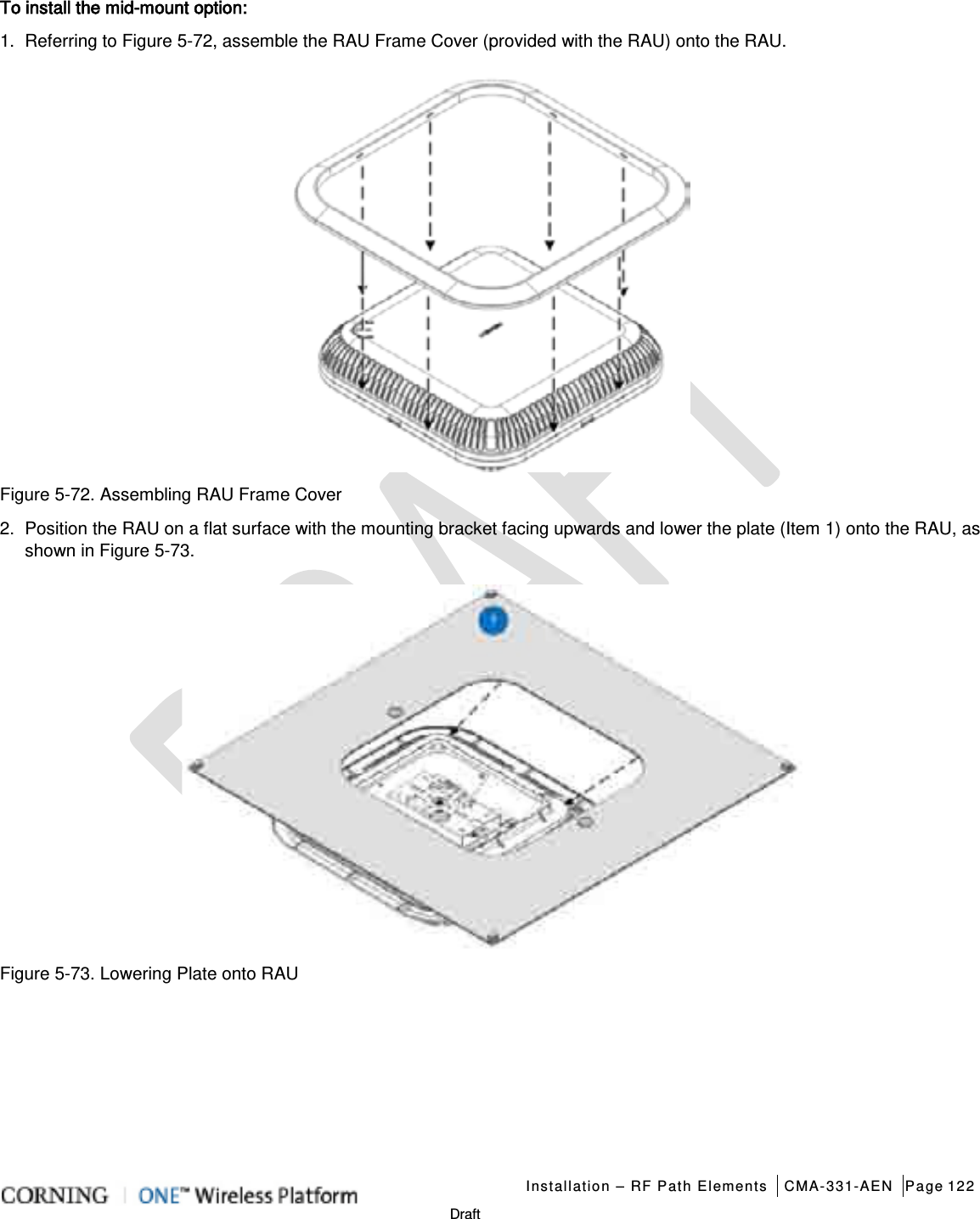
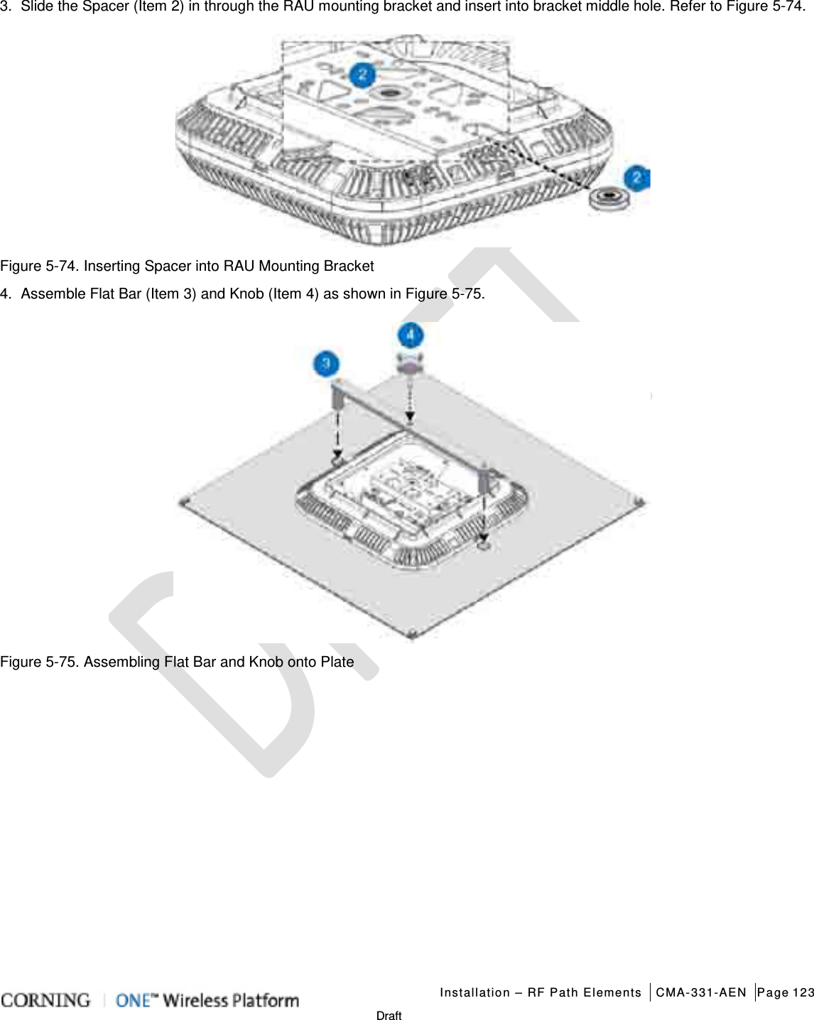
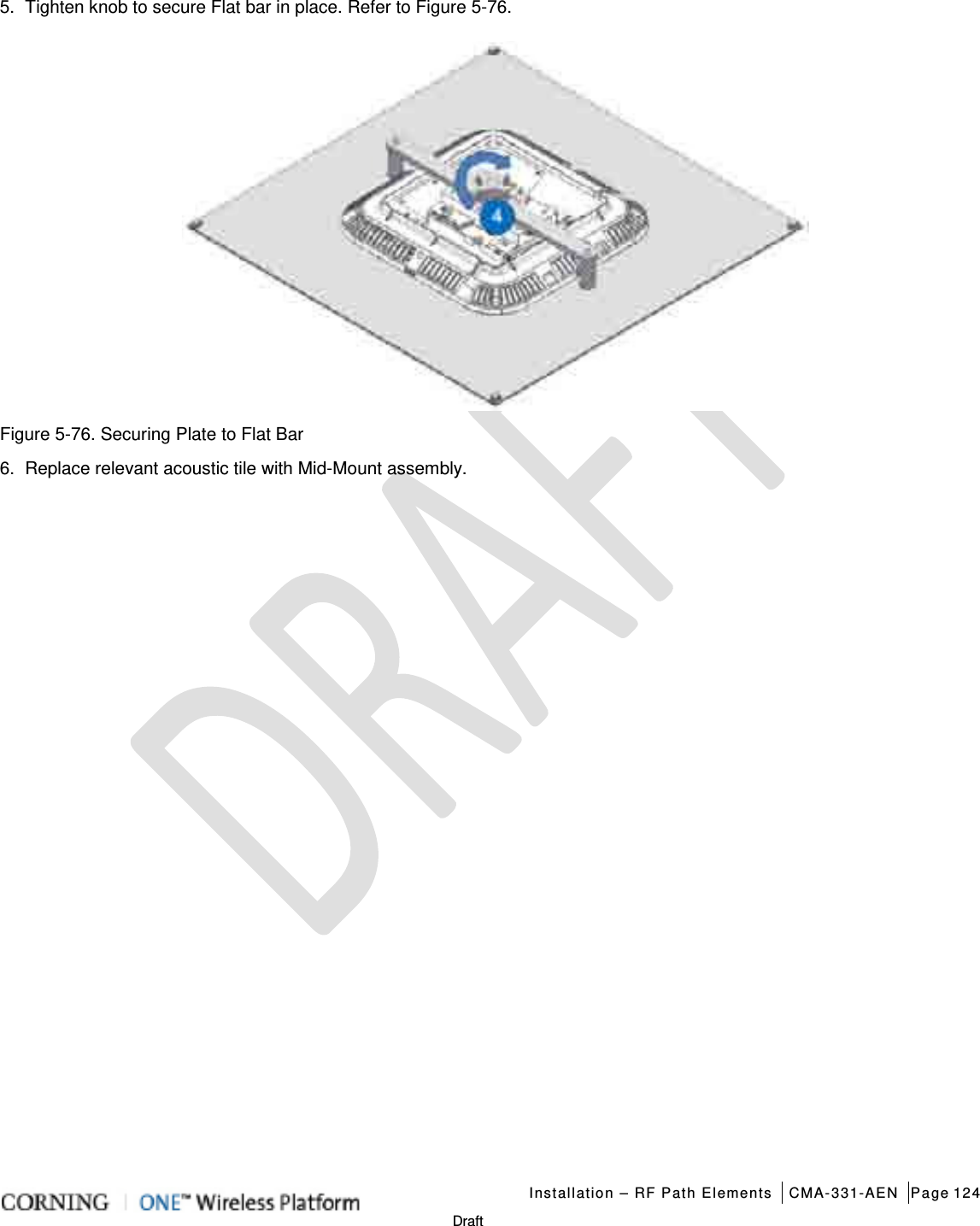
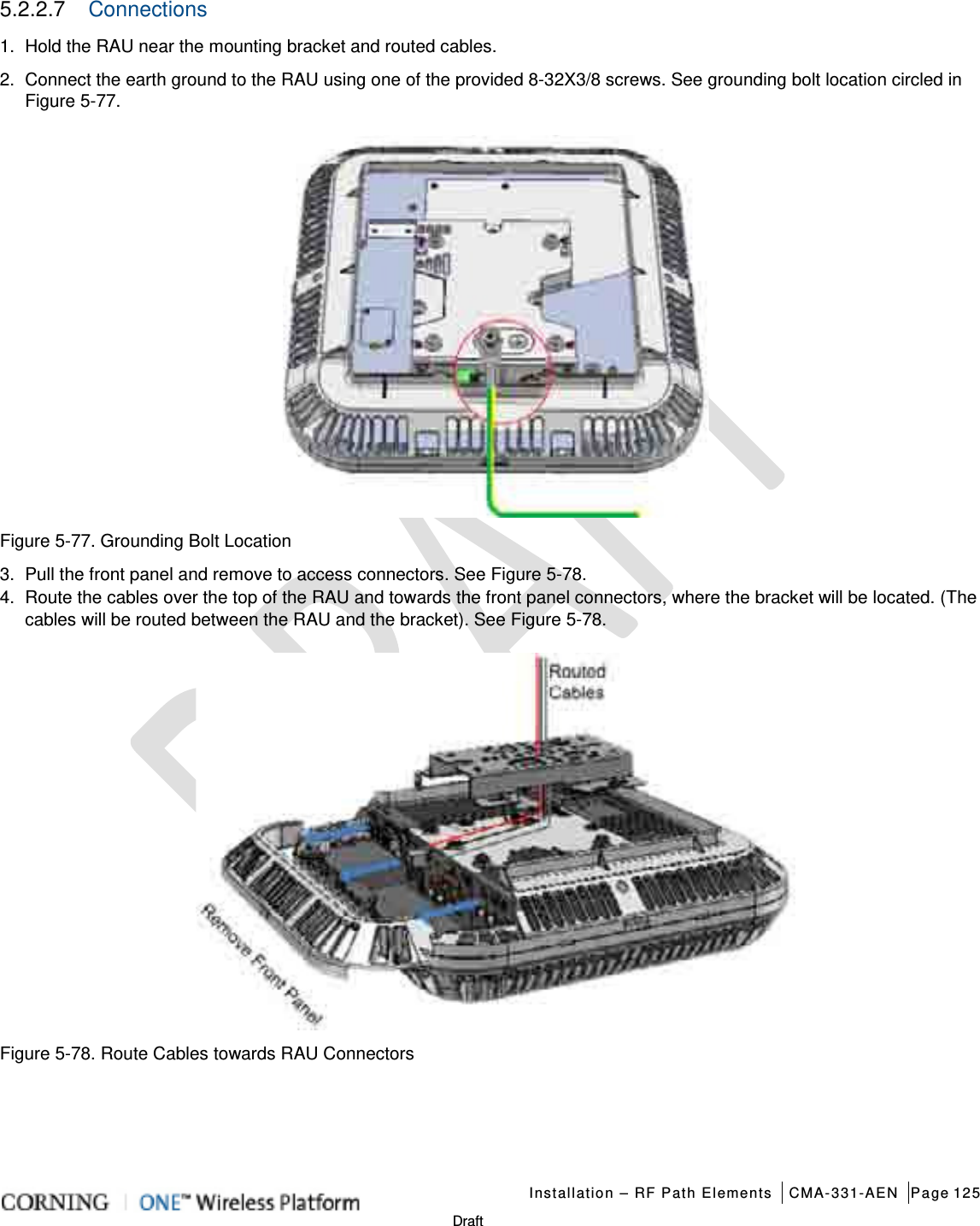
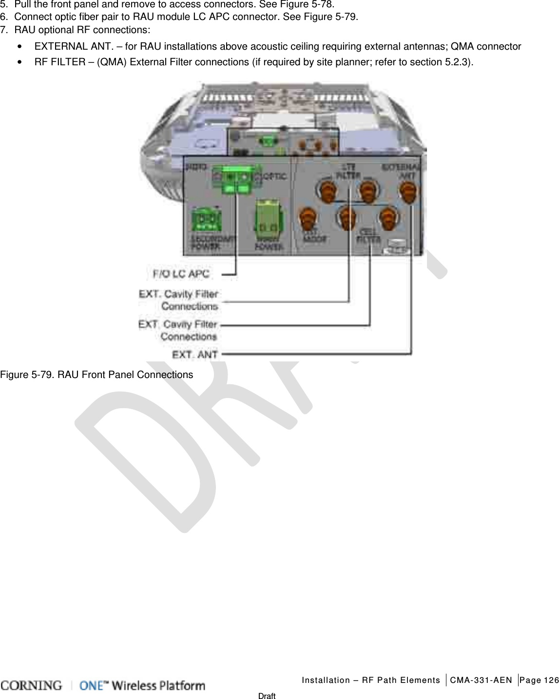
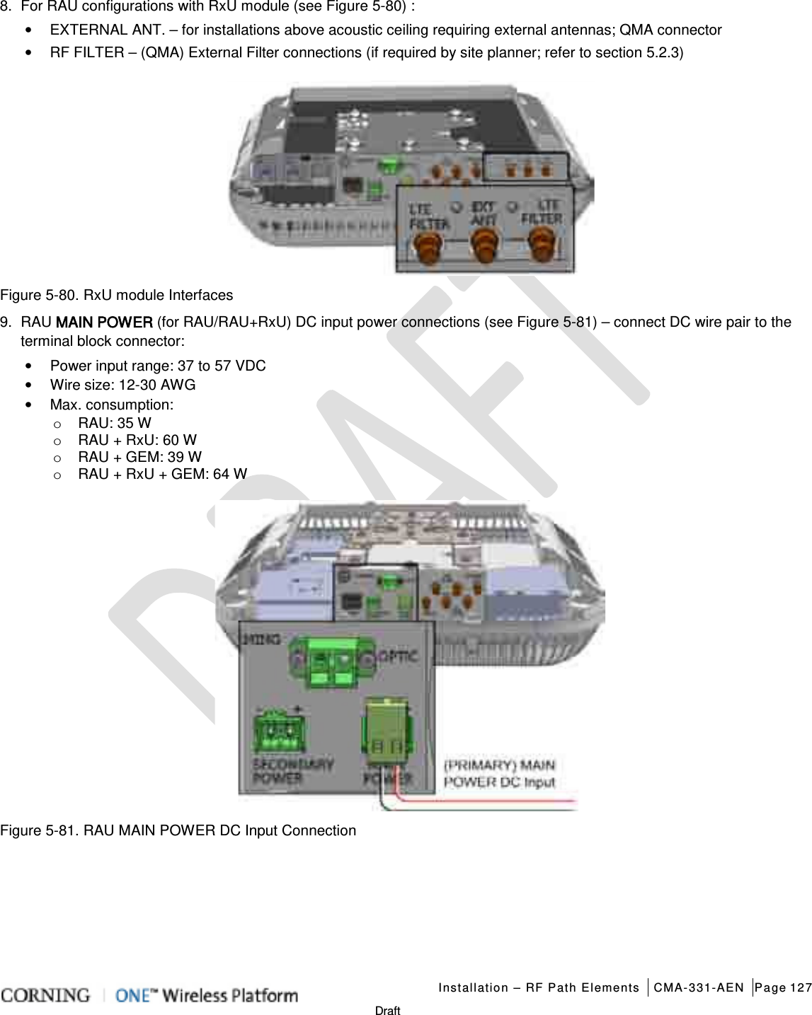
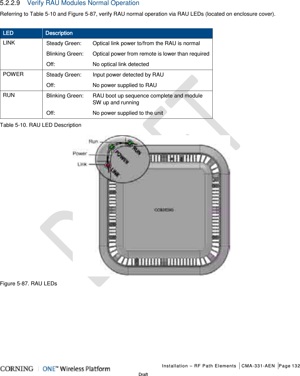
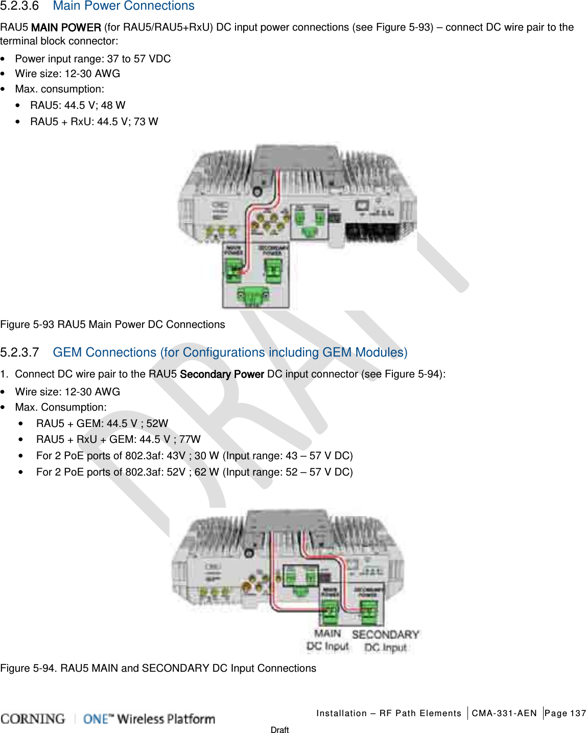
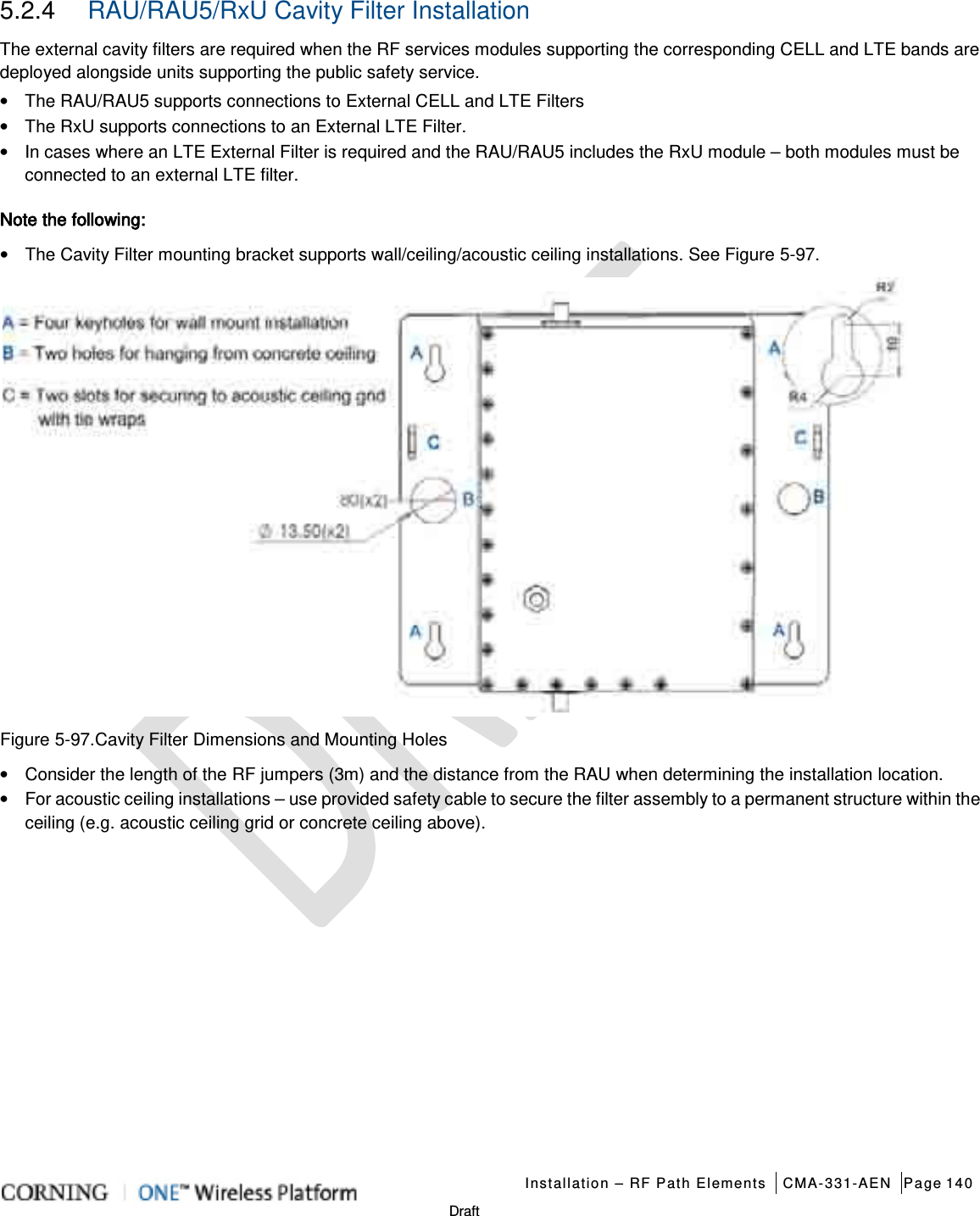
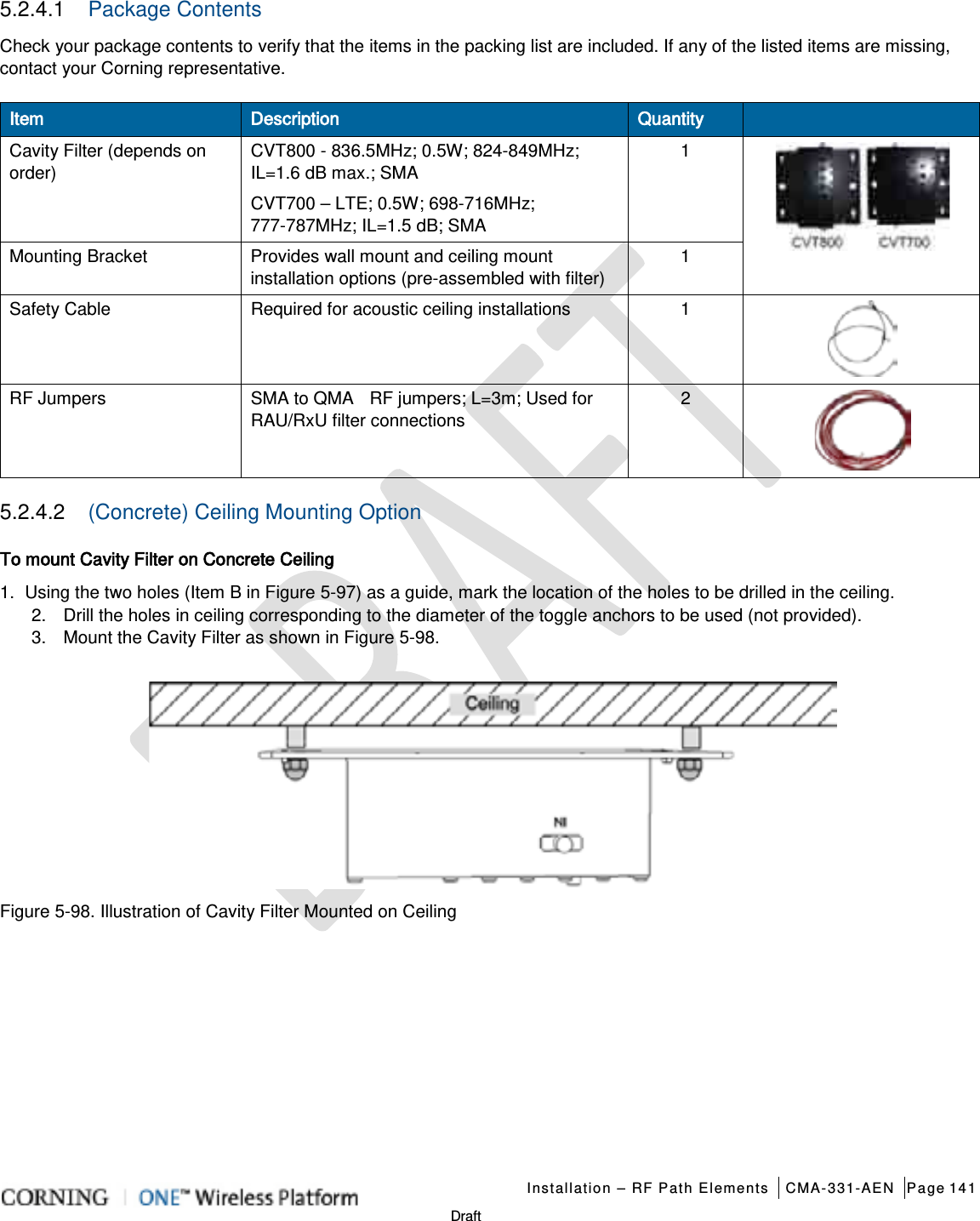
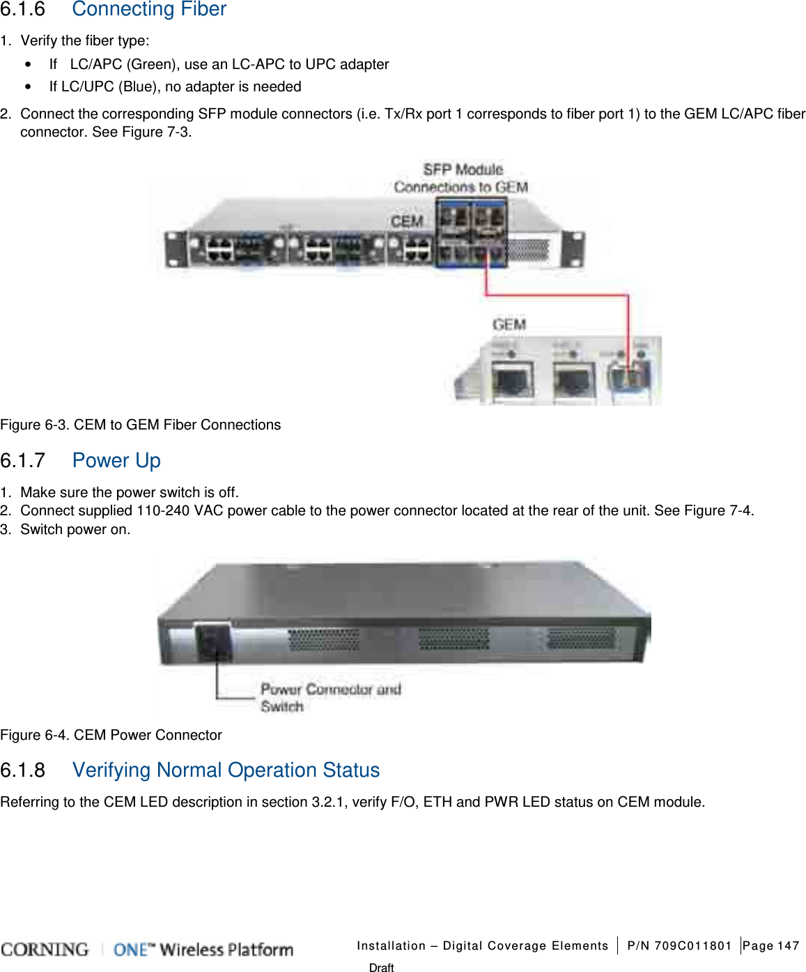
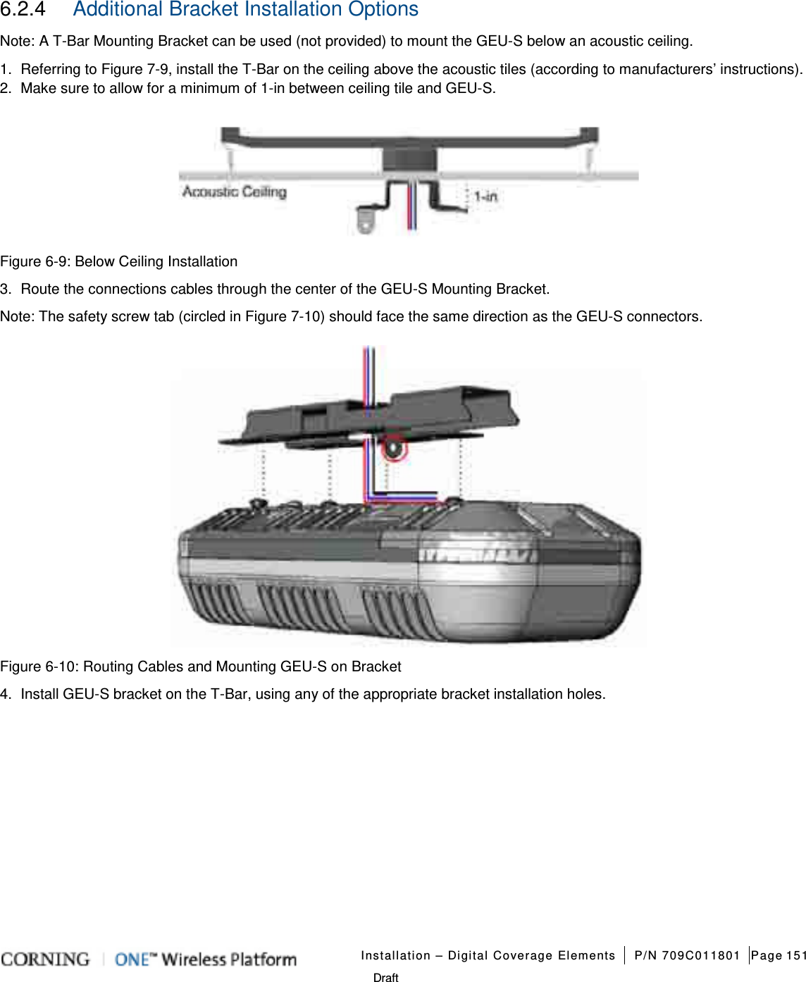
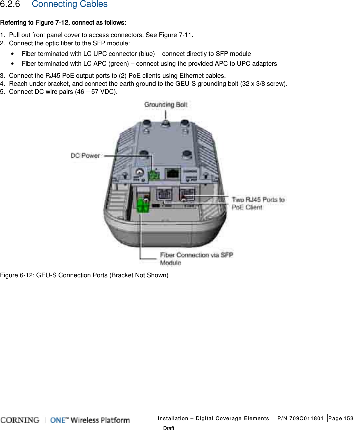
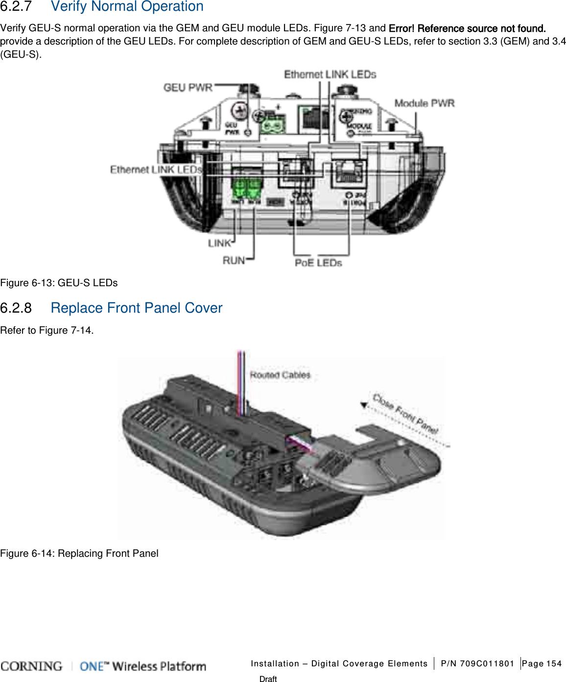
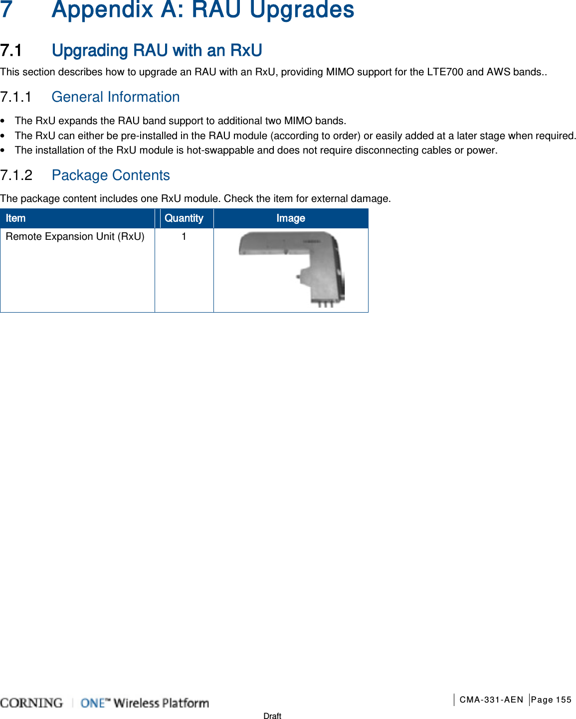
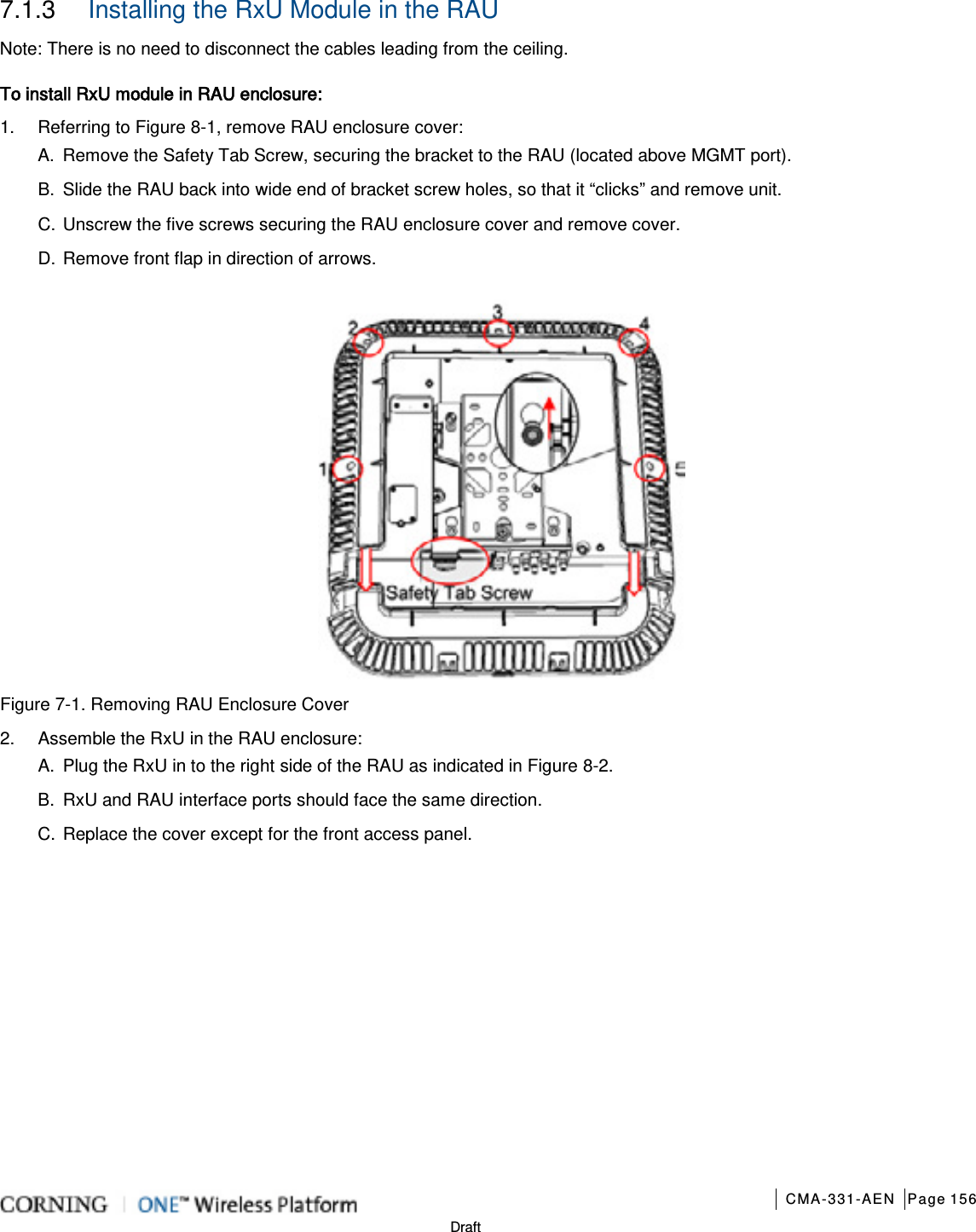
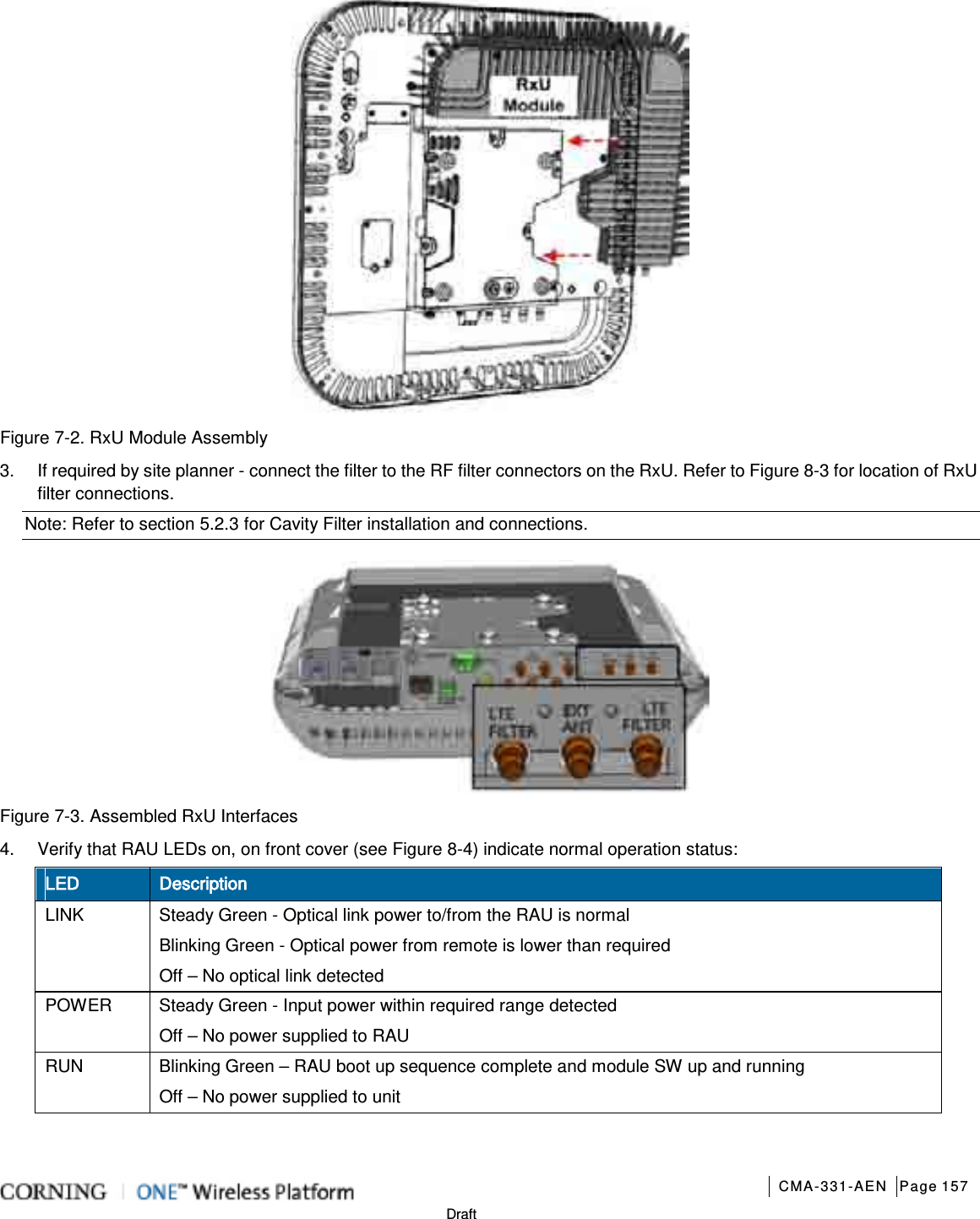
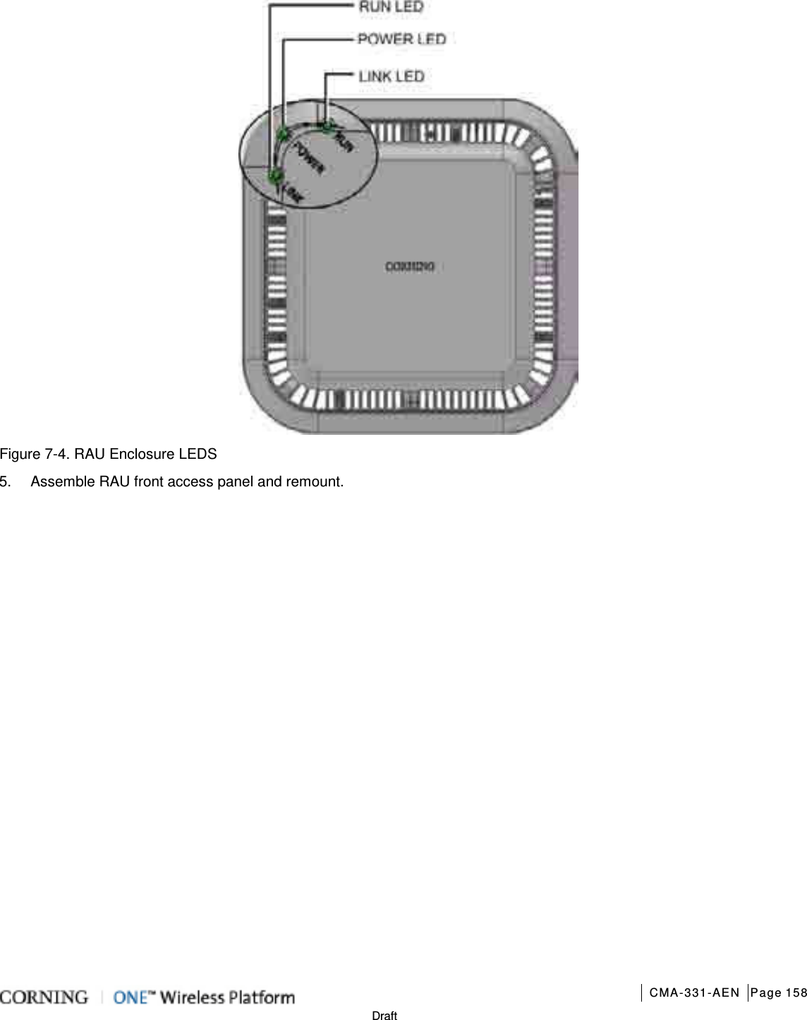
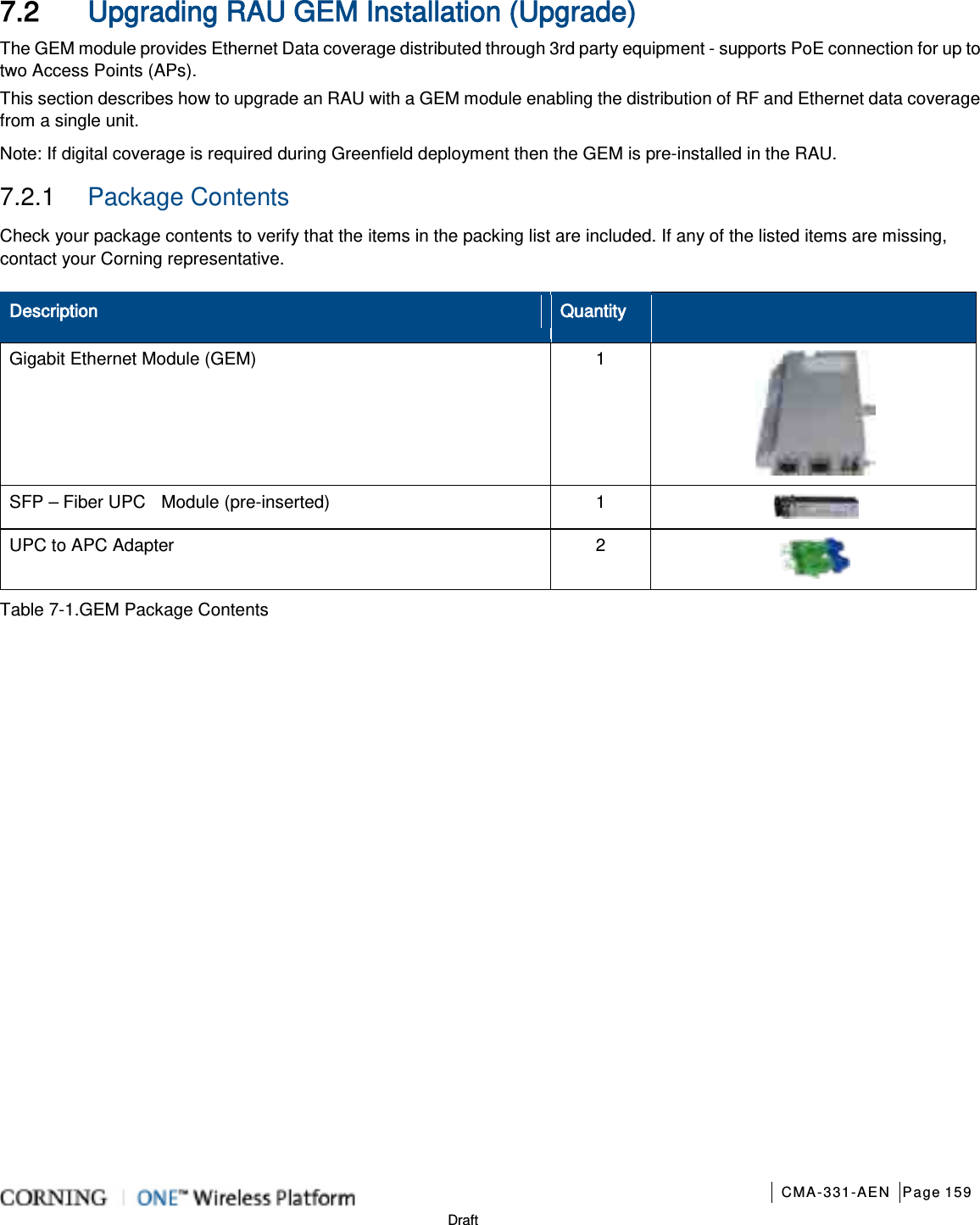
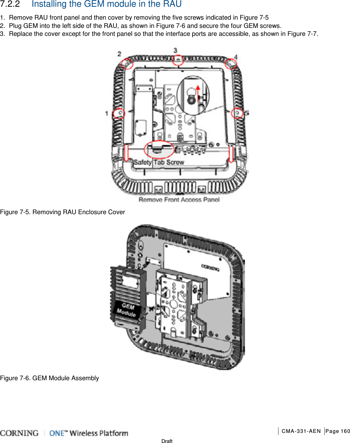
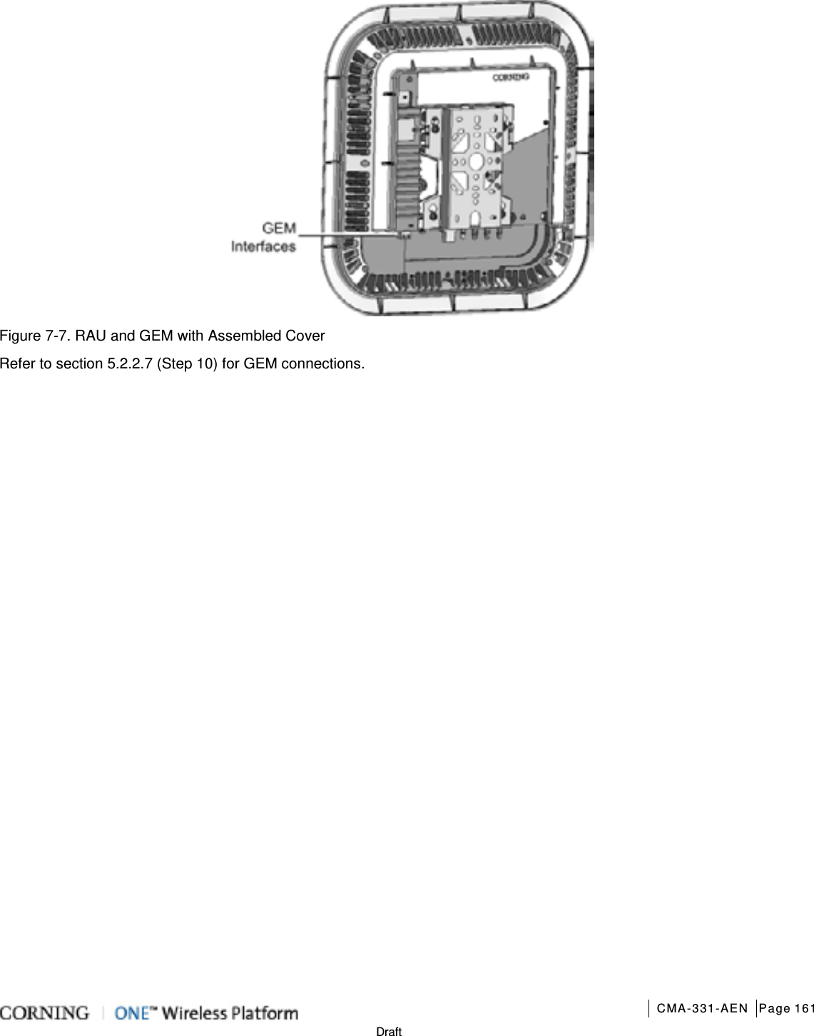
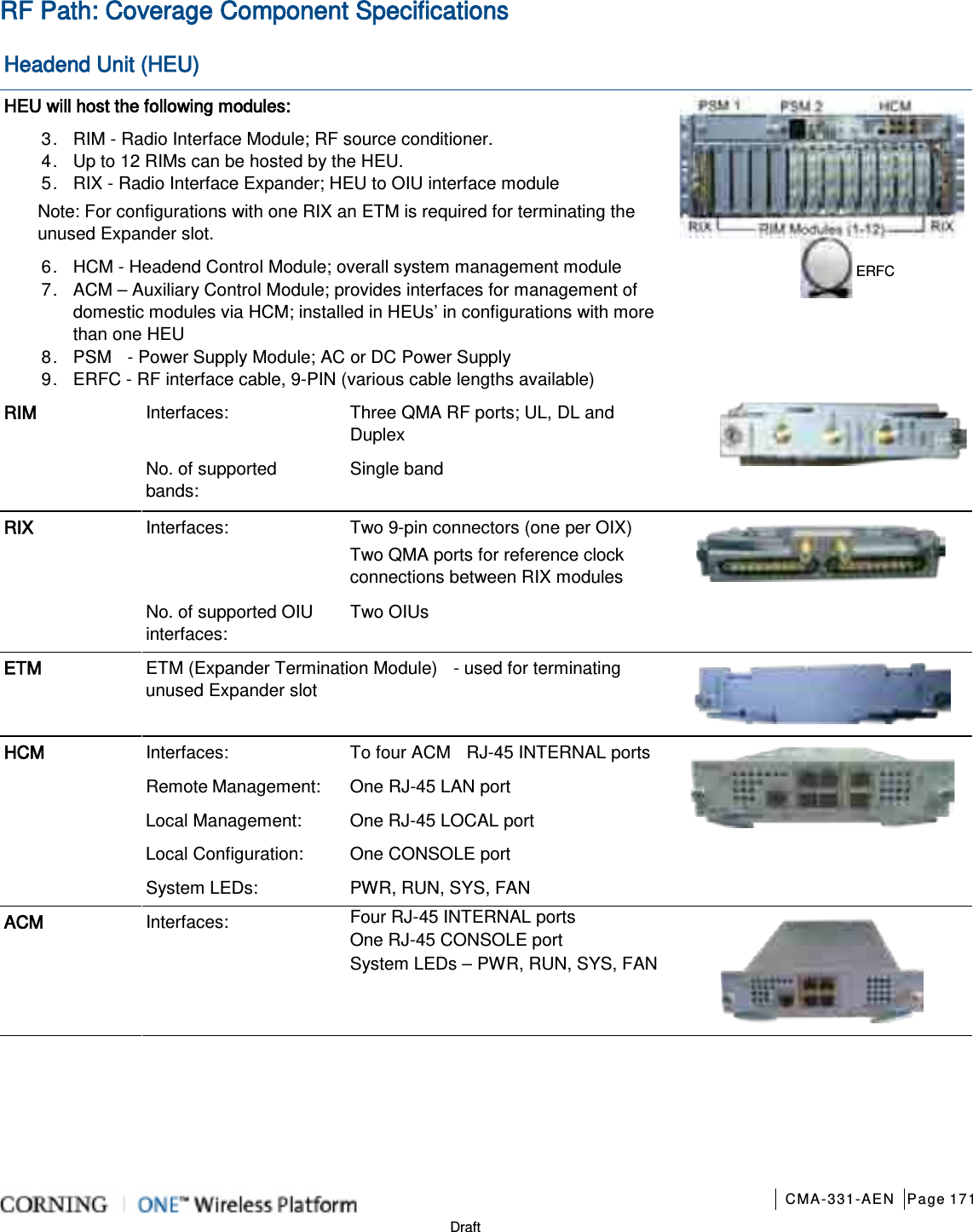
![Installation – RF Path Elements CMA-331-AEN Page 116 Draft 5.2.2 RAU Installation 5.2.2.1 General Information 1. The RAU modules are deployed on the floor level and interface to the RF antennas. 2. The RAU can be provided in a number of configurations: • RAU alone (without RxU and GEM); weight = 7.93 lbs (3.6 kg) • RAU + RxU • RAU + GEM • RAU + RxU + GEM; weight = 12.12 lbs (5.5 kg) Note: Existing RAU units can be upgraded with RxU (for MIMO support) and/or GEM modules (for Ethernet services) – see Appendix A for instructions on how to upgrade the RAU with these modules. 3. The RAU supports various mounting installation options: • Wall-mount installations (vertical); required ambient temperature of 45◦C [113◦F] • Ceiling-mount installations (horizontal): required ambient temperature of 45◦C 50◦C [122◦F] Note: If the RAU is installed below or mid-mount an acoustic ceiling, a support bar (T-Bar) is required (not included). Acoustical ceiling grid work is not designed to support the weight of the enclosure. 4. The RAU unit is provided with a mounting bracket used for mounting on the wall or concrete ceilings (including above acoustic ceiling mounts). Additional below/mid-mount acoustic ceiling mounting options are possible using a T-Bar mounting bracket (not provided). 5. RAU optic fiber connections and DC power are provided via a Corning Composite cable (ordered separately). 6. External cavity filters (AK-CVT700; AK-CVT800) are required for installations in which RAU/RXU modules supporting the corresponding CELL and LTE bands are deployed alongside units supporting the public safety service. See section 5.2.3 for installation instructions. 5.2.2.2 Package Contents Check your package contents to verify that the items in the packing list are included. If any of the listed items are missing, contact your Corning representative. Item Quantity Image Remote Access Unit (RAU): RAU-R-G-C85P19L70A17-ME RAU-R-C85P19L70A17-M RAU-G-C85P19L70A17-E RAU-C85P19L70A17 1 Mounting Bracket (factory assembled on RAU underside) Note: Mounting Bracket includes holes in various sizes and locations for flexible installation options. Mounting screws not provided. 1 Screw, SEM 8-32X3/8 , Pan Head, Philips - used for grounding and to secure bracket to RAU 2 “Skirt” Frame Cover – used for acoustic ceiling cut-out template and for aesthetic installation 1 Safety Cable – used to secure RAU to permanent structure in acoustic ceiling installations; connected to RAU 1](https://usermanual.wiki/Corning-Optical-Communication/1RAU5/User-Guide-2485046-Page-116.png)
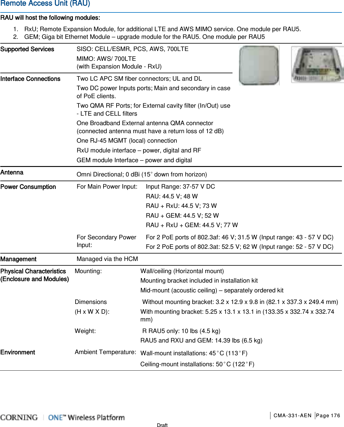
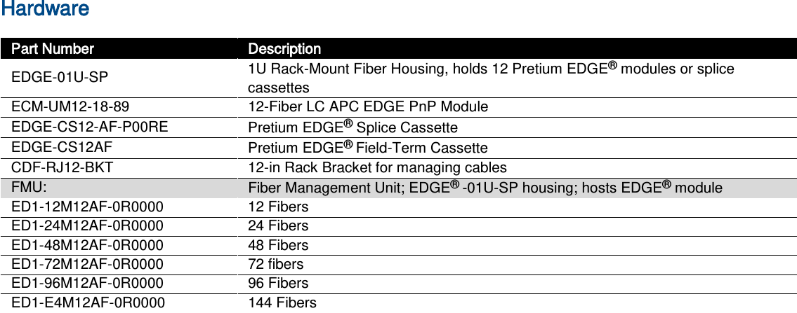
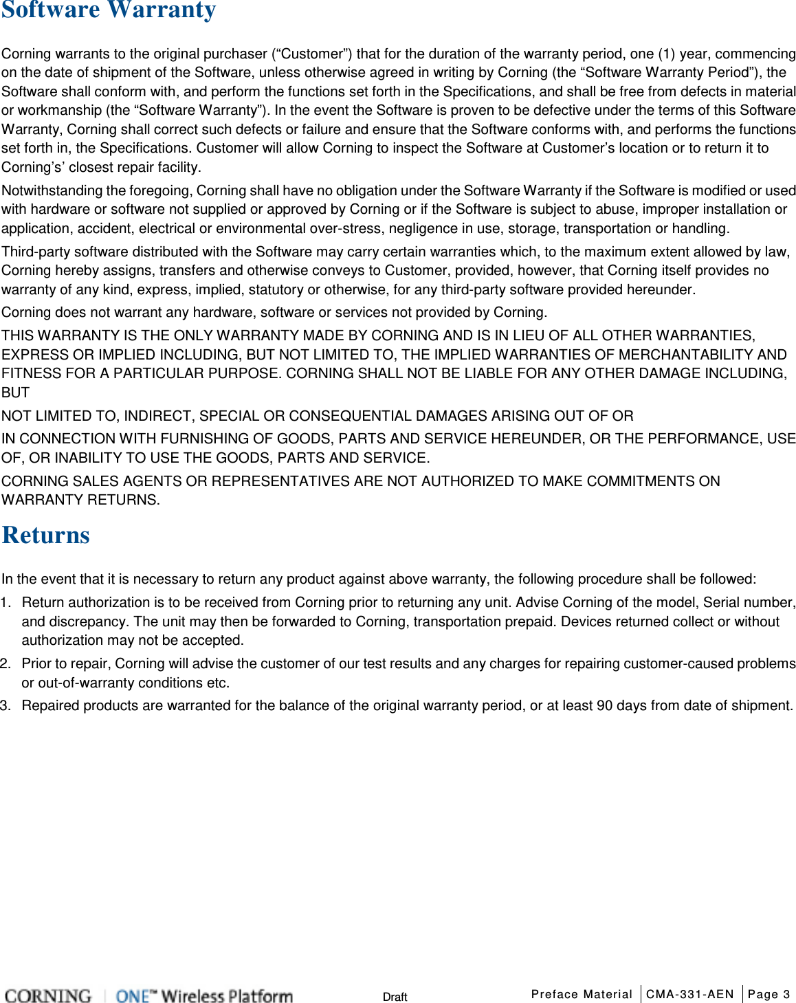
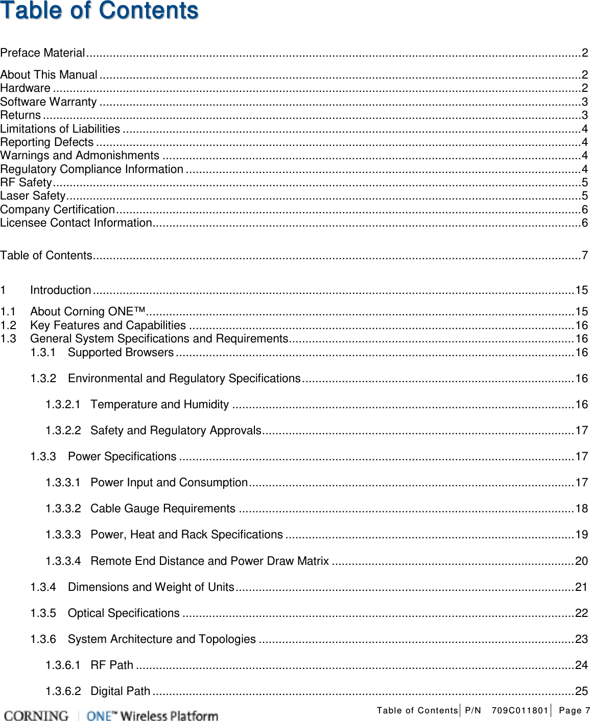
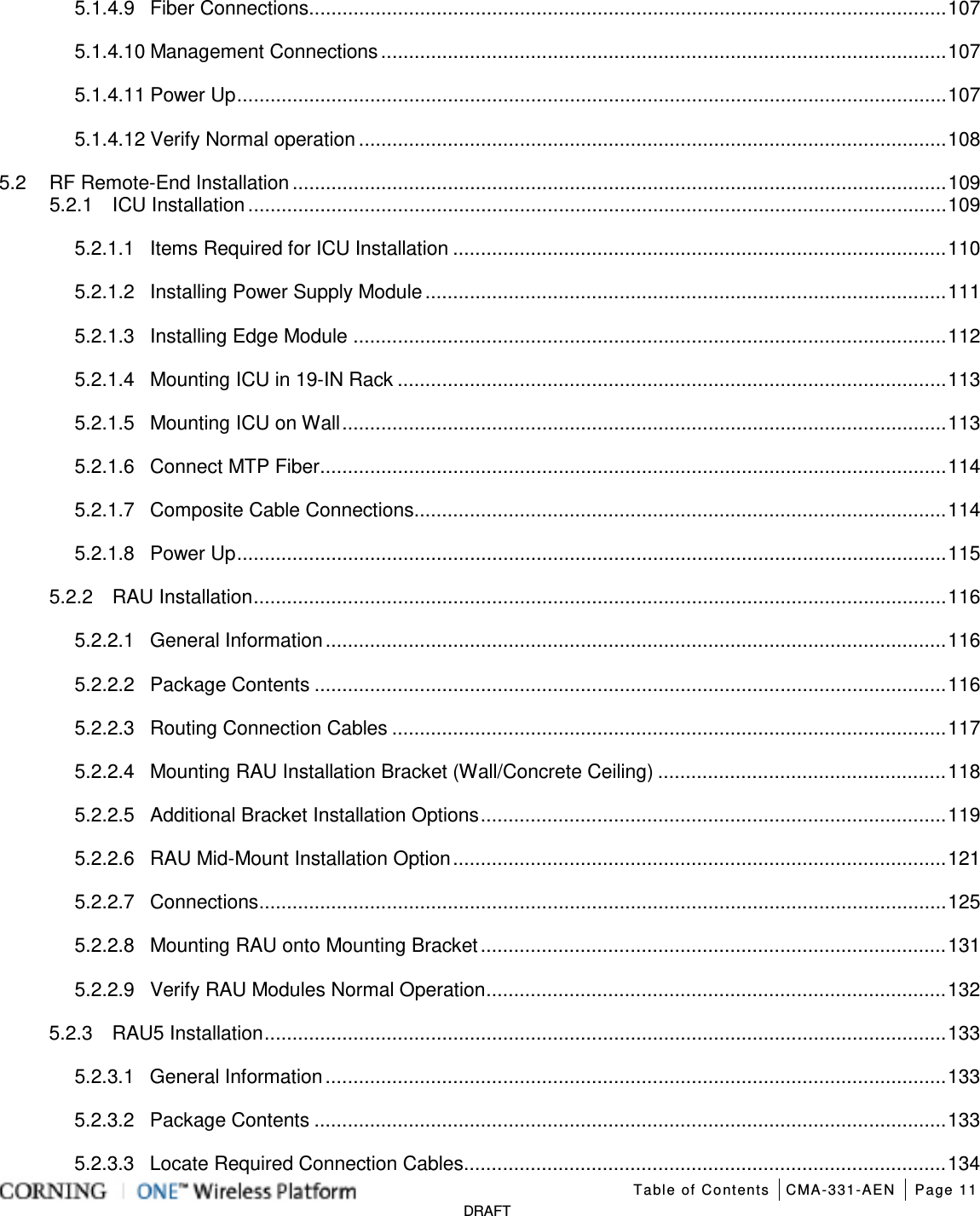
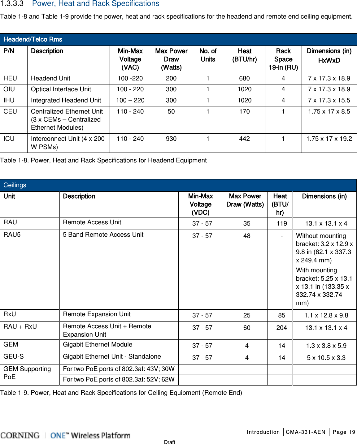
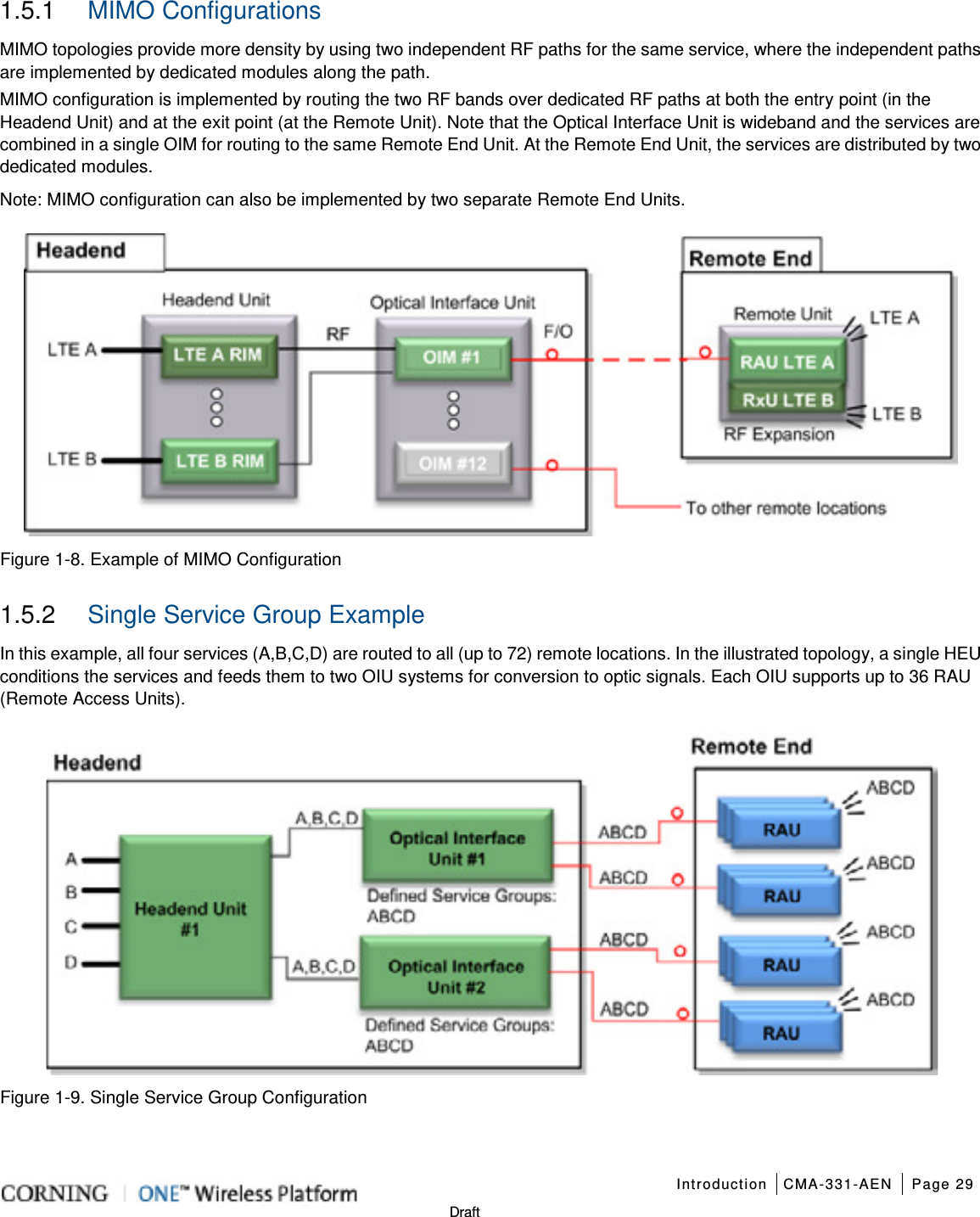
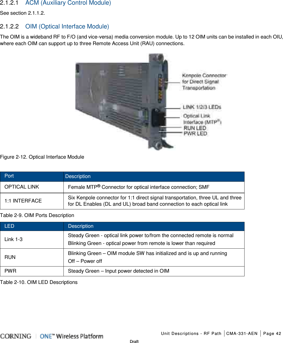
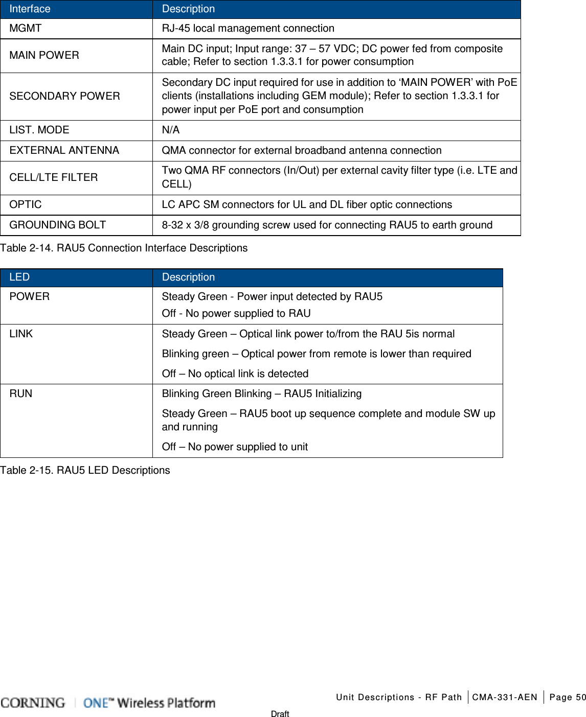
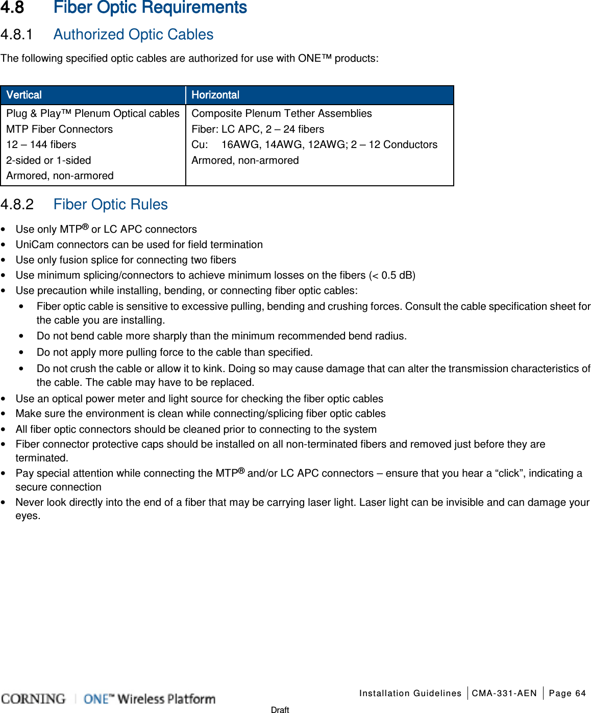
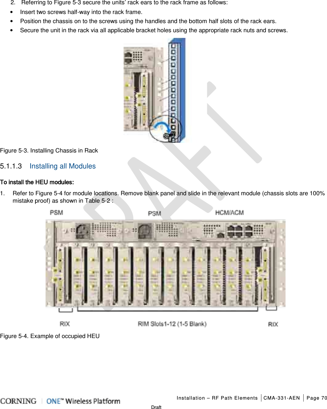
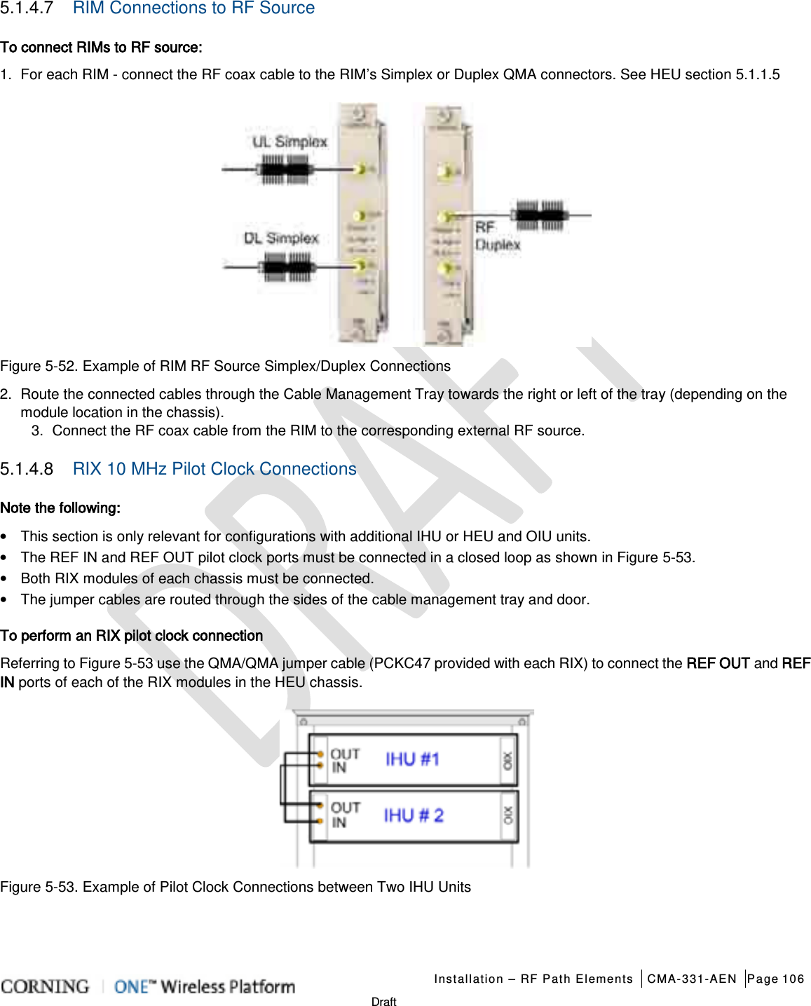
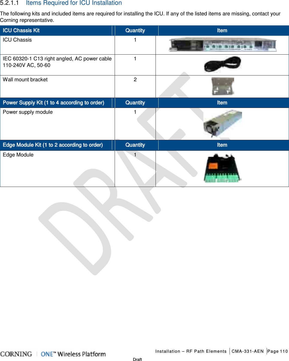
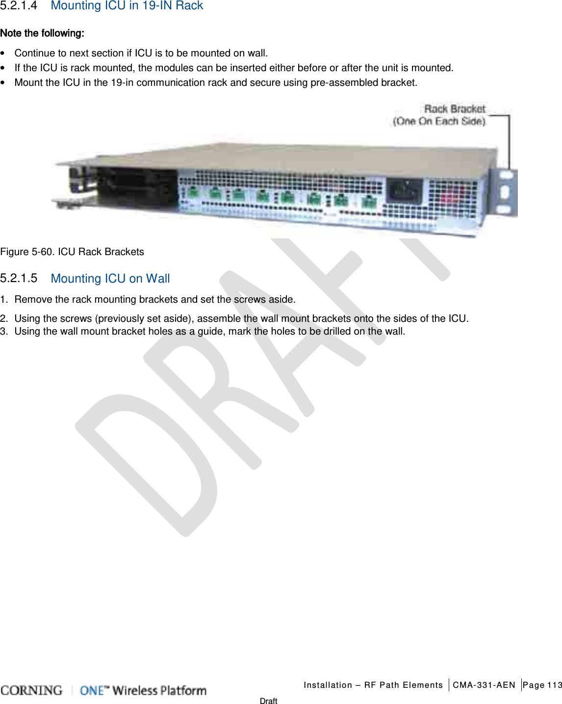
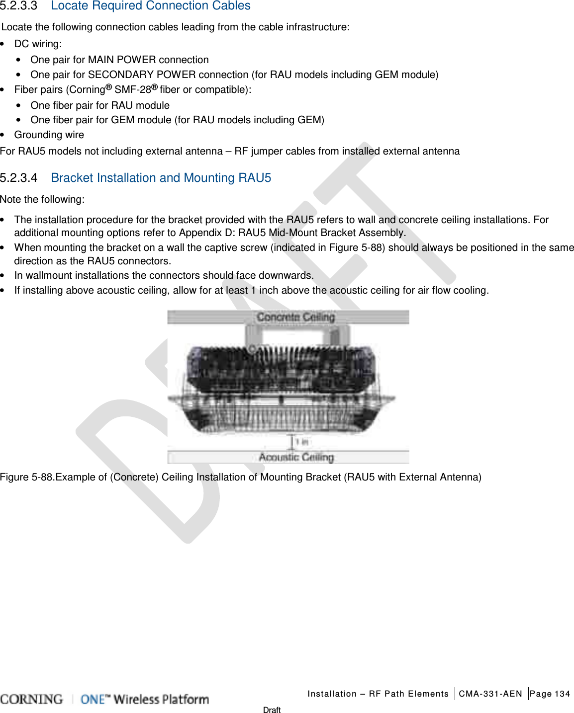
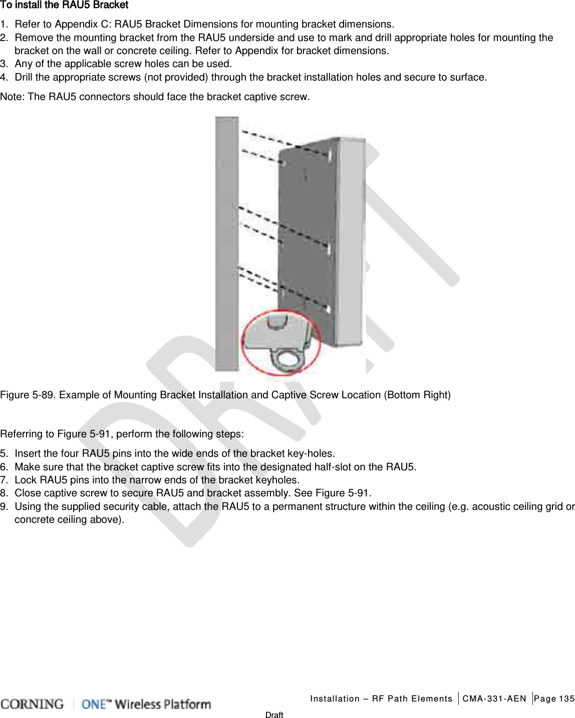
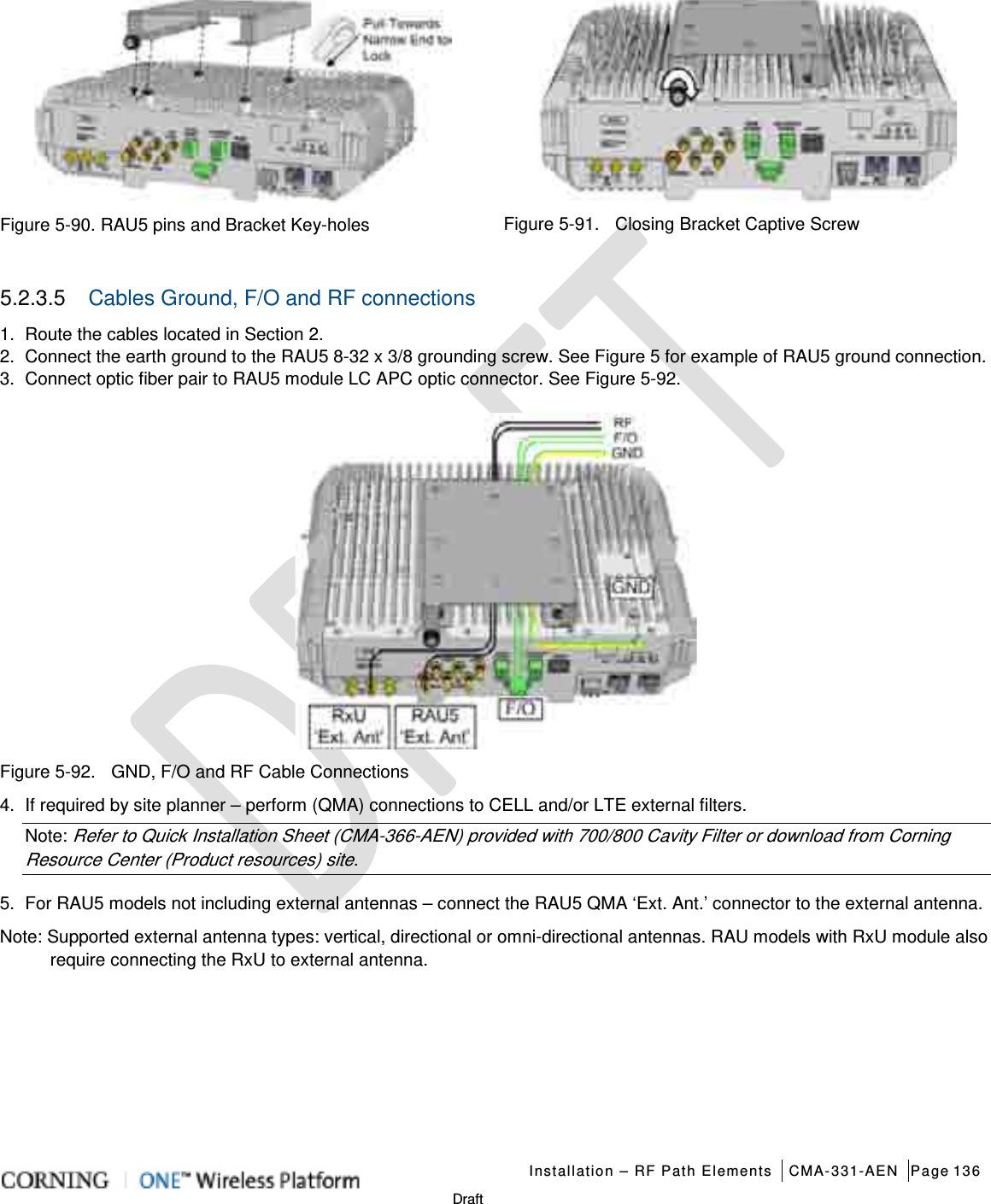
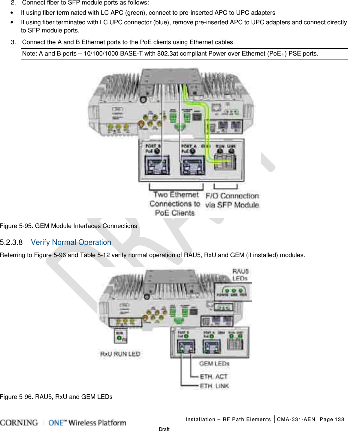
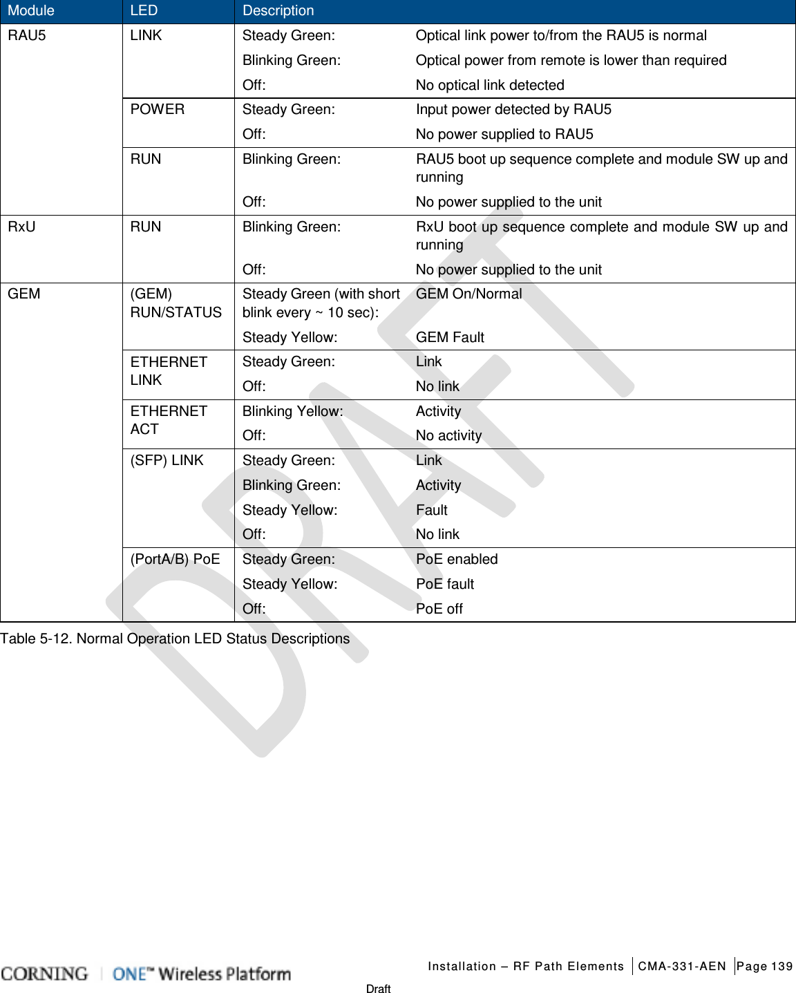
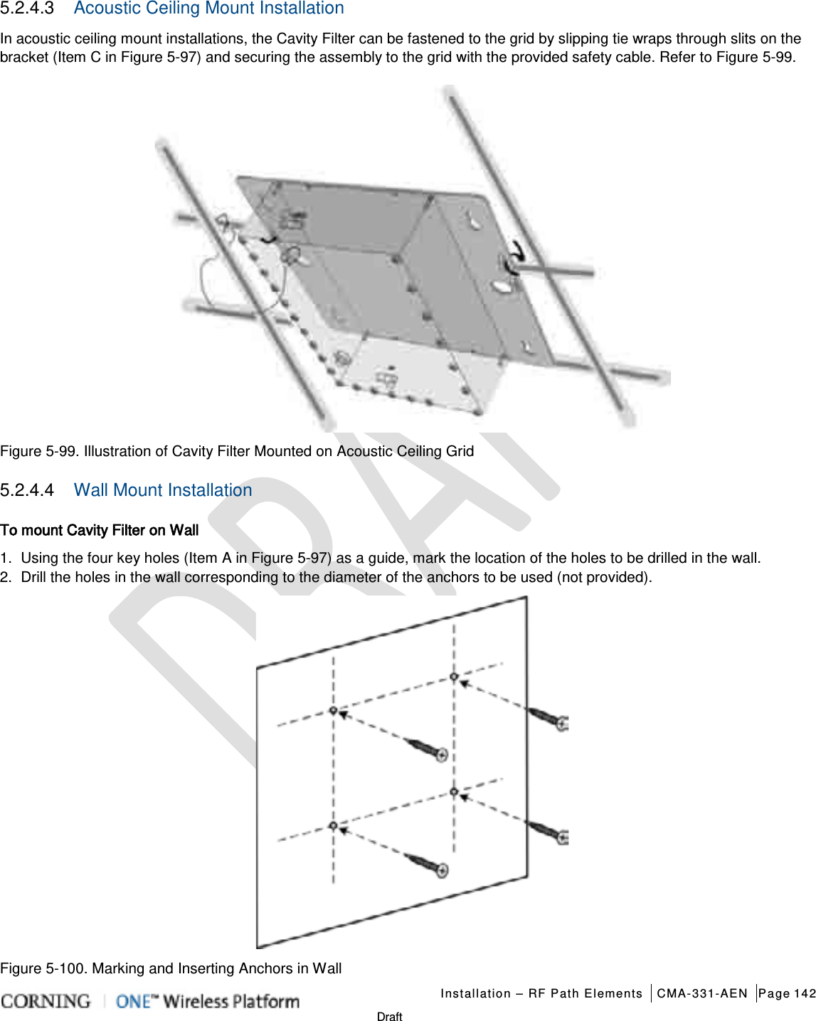
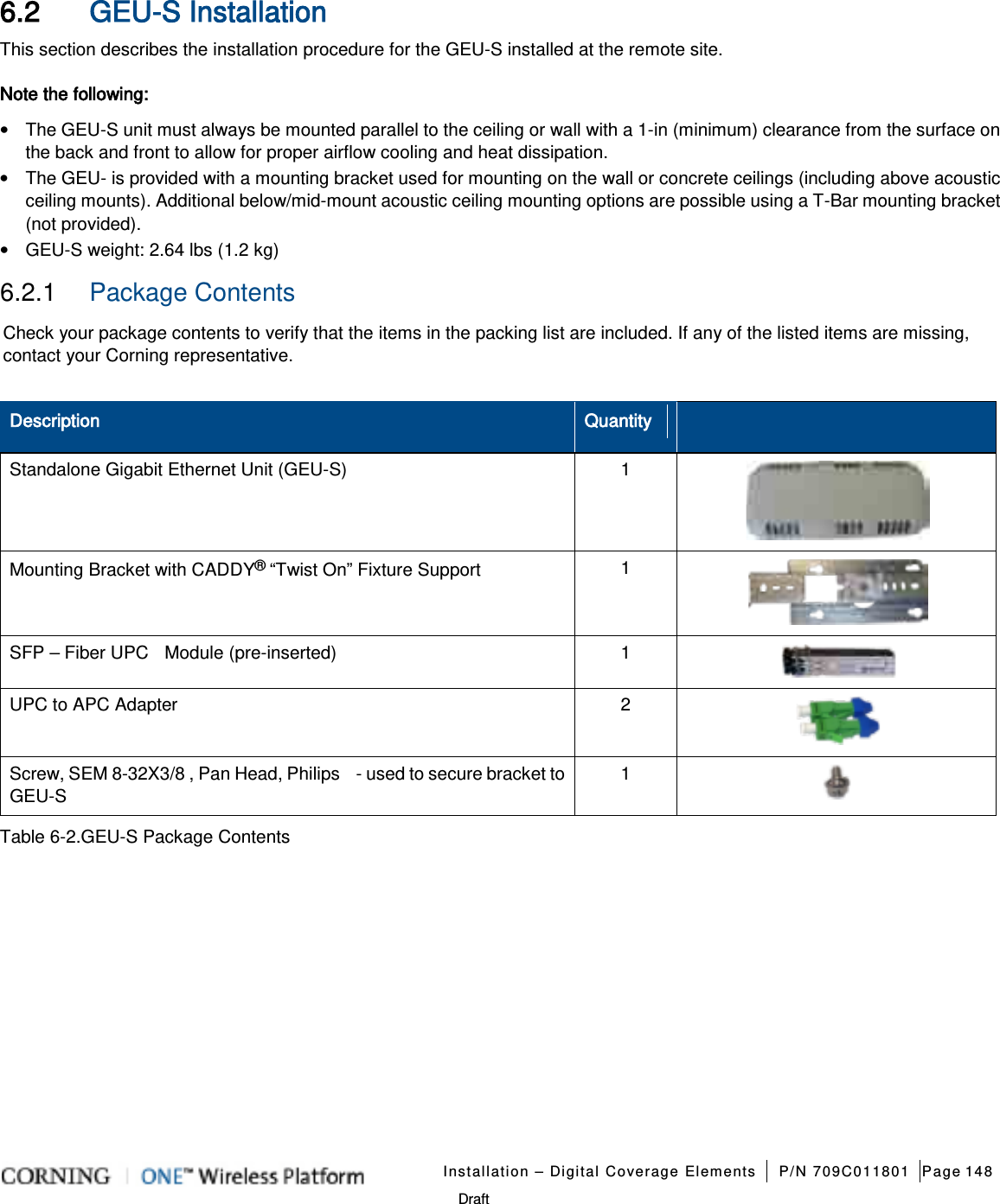
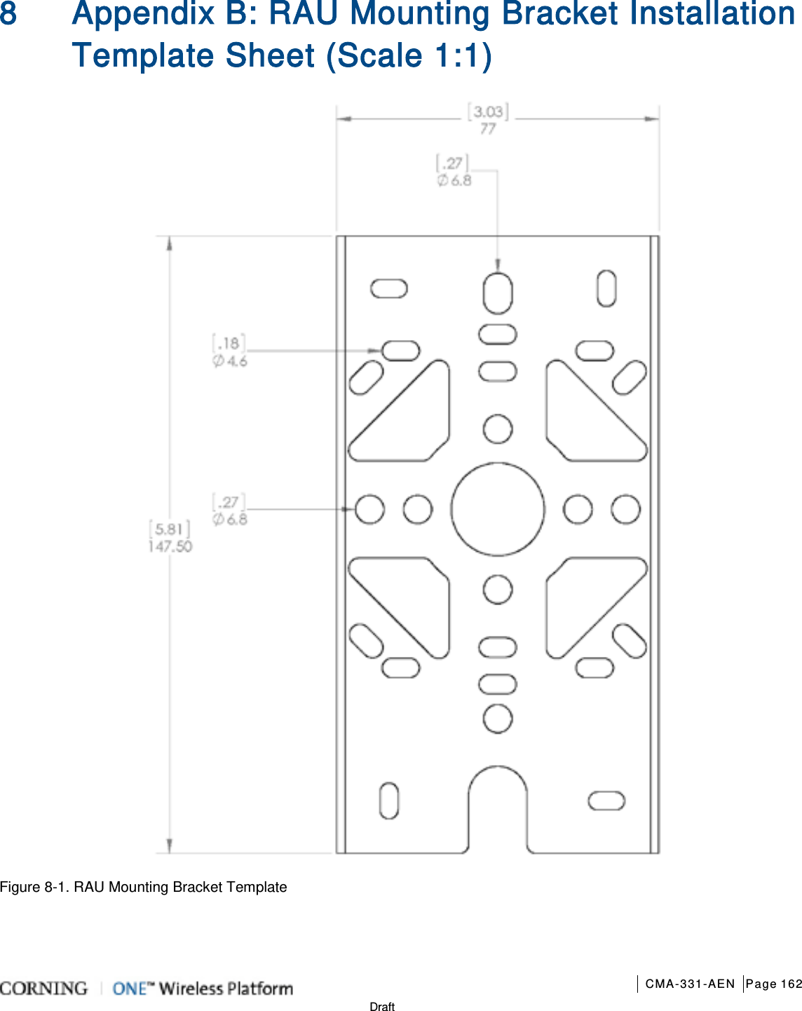
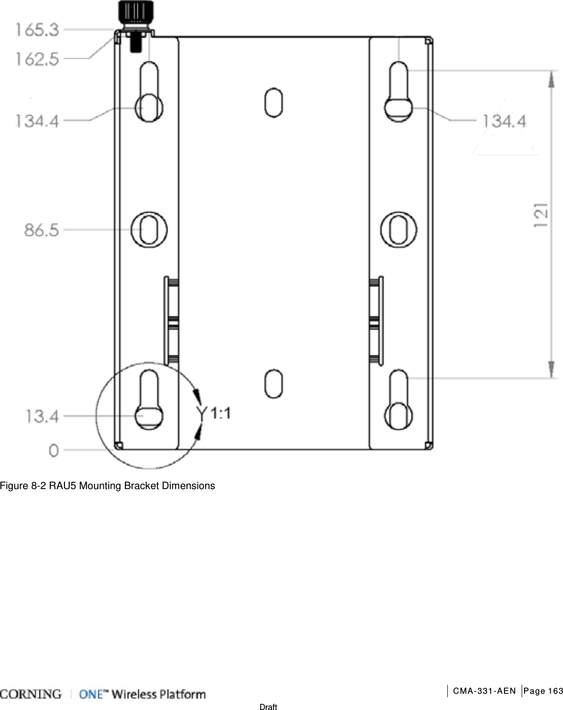
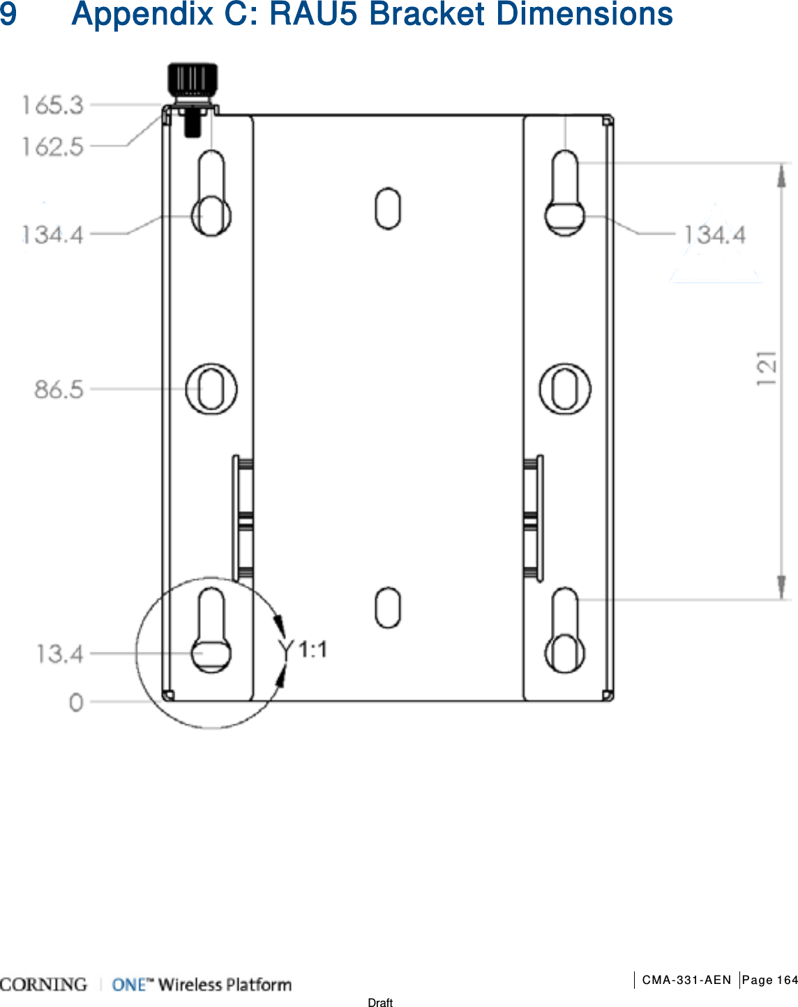
![Installation – RF Path Elements CMA-331-AEN Page 133 Draft 5.2.3 RAU5 Installation 5.2.3.1 General Information 1. The RAU5 must always be mounted parallel to the ceiling (horizontal) or wall (vertical) with a 1-in clearance from the surface on the back and front to allow for proper cooling airflow and for heat dissipation. 2. Required ambient temperature: • Wall-mount installations (vertical): 45◦C [113◦F] • Ceiling-mount installations (horizontal): 50◦C [122◦F] 3. The RAU5 unit is provided with a mounting bracket used for mounting on the wall or concrete ceilings (including above acoustic ceiling mounts). Additional mounting accessory kits are available (ordered separately): • BR-RAU5US-TOP: RAU5 bracket for floating ceilings tile, Mid-Mount installation • BR-RAU5US-Wall: RAU5 remote bracket for wall mount installation; Supports up to two RAU5 units back-to-back 4. RAU5 weight: • RAU5 Alone: 10 lbs (4.54 kg) • RAU5 + RxU + GEM: 14.39 lbs (6.5 kg) 5. A broadband antenna is required for RAU5 models ordered without a preassembled connected antenna (see Table 5-11 for RAU5 models). 6. External cavity filters are required for installations in which RAU5/RXU modules supporting the corresponding CELL and LTE bands are deployed alongside units supporting the public safety service. Installation instructions (Quick Start Guide) are provided with each separately ordered filter (AK-CVT700; AK-CVT800). 5.2.3.2 Package Contents Note: Check your package contents to verify that the items in the packing list are included. If any of the listed items are missing, contact your Corning representative. Item Quantity Remote Access Unit (RAU5): • RAU5US • RAU5US-A* • RAU5US-E • RAU5US-AE* • RAU5US-ME • RAU5US-AM* • RAU5US-M • RAU5US-AME* *RAU5 model including assembled external broadband antenna 1 Mounting Bracket (preassembled on RAU5 underside) Note: Mounting Bracket includes holes in various sizes and locations for flexible installation options. Screws for mounting on surfacMounting screws not provided. 1 Safety Cable – preconnected to the RAU5 1 Table 5-11 RAU5 Package Contents](https://usermanual.wiki/Corning-Optical-Communication/1RAU5/User-Guide-2485046-Page-133.png)
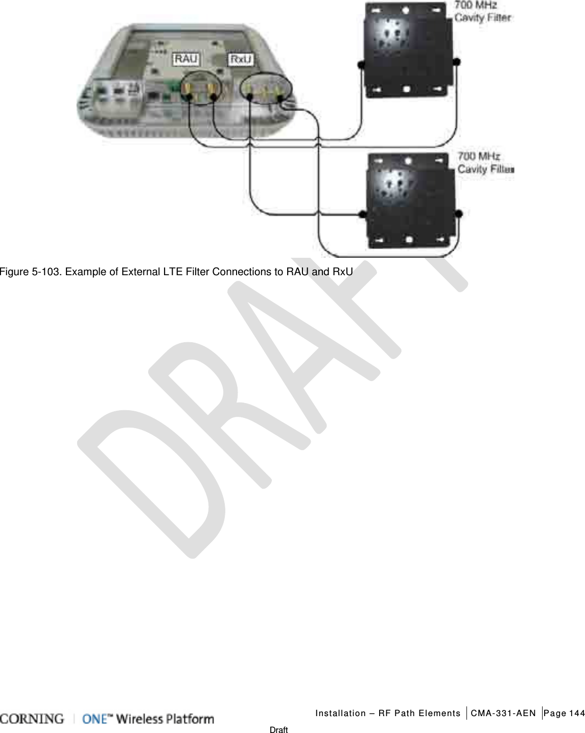
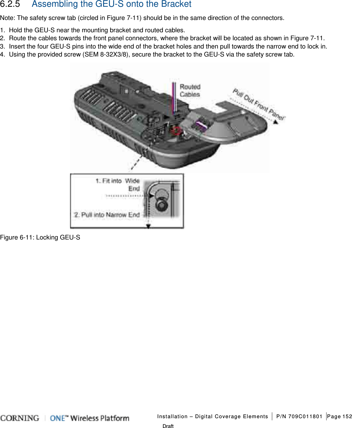
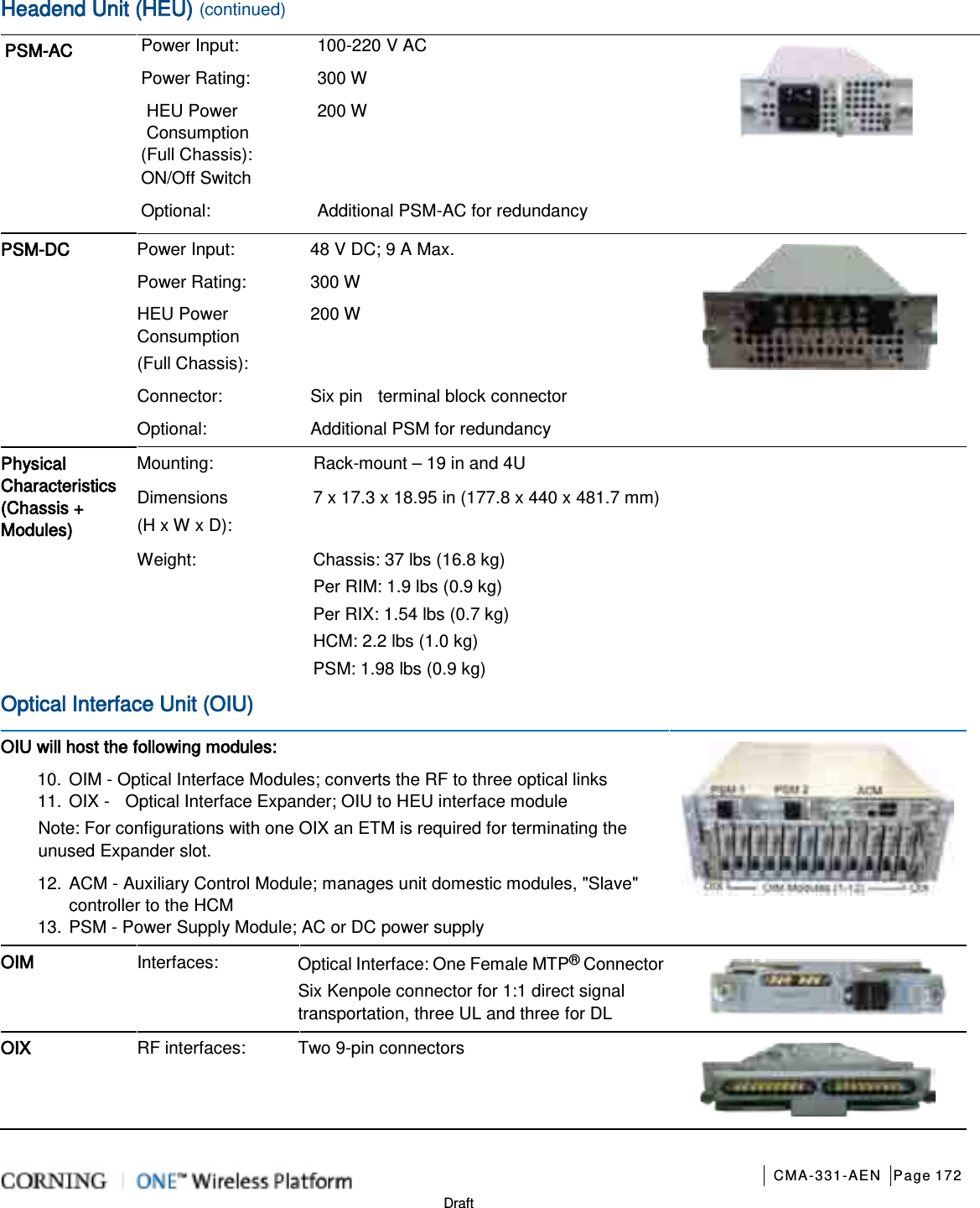
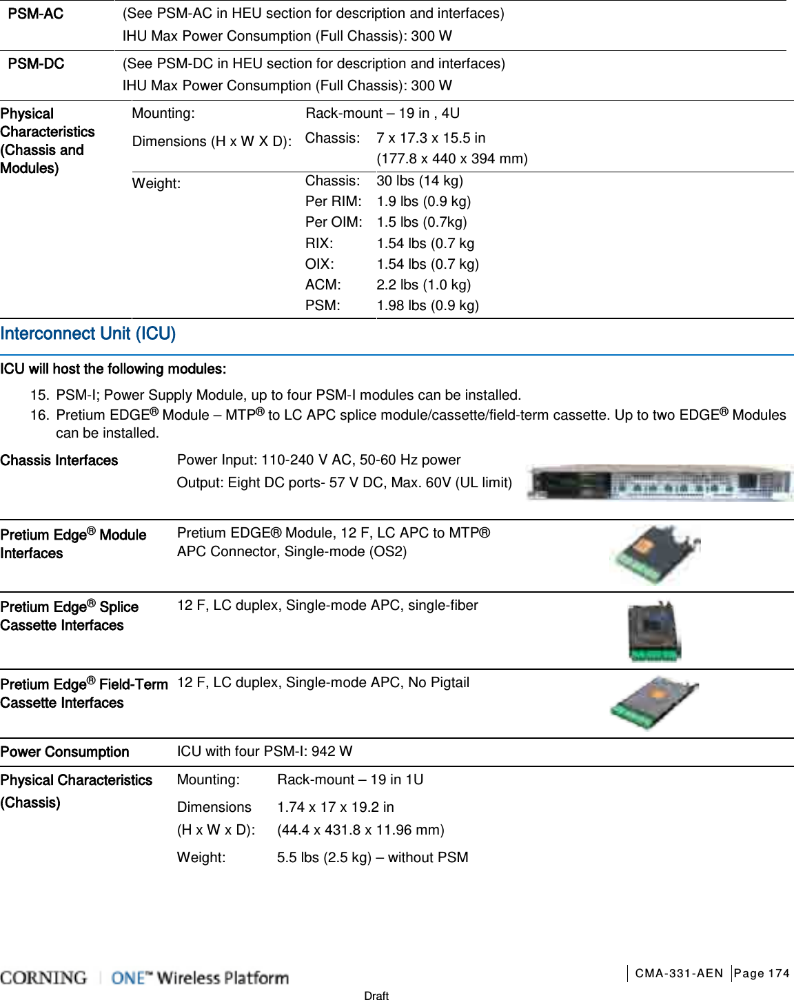
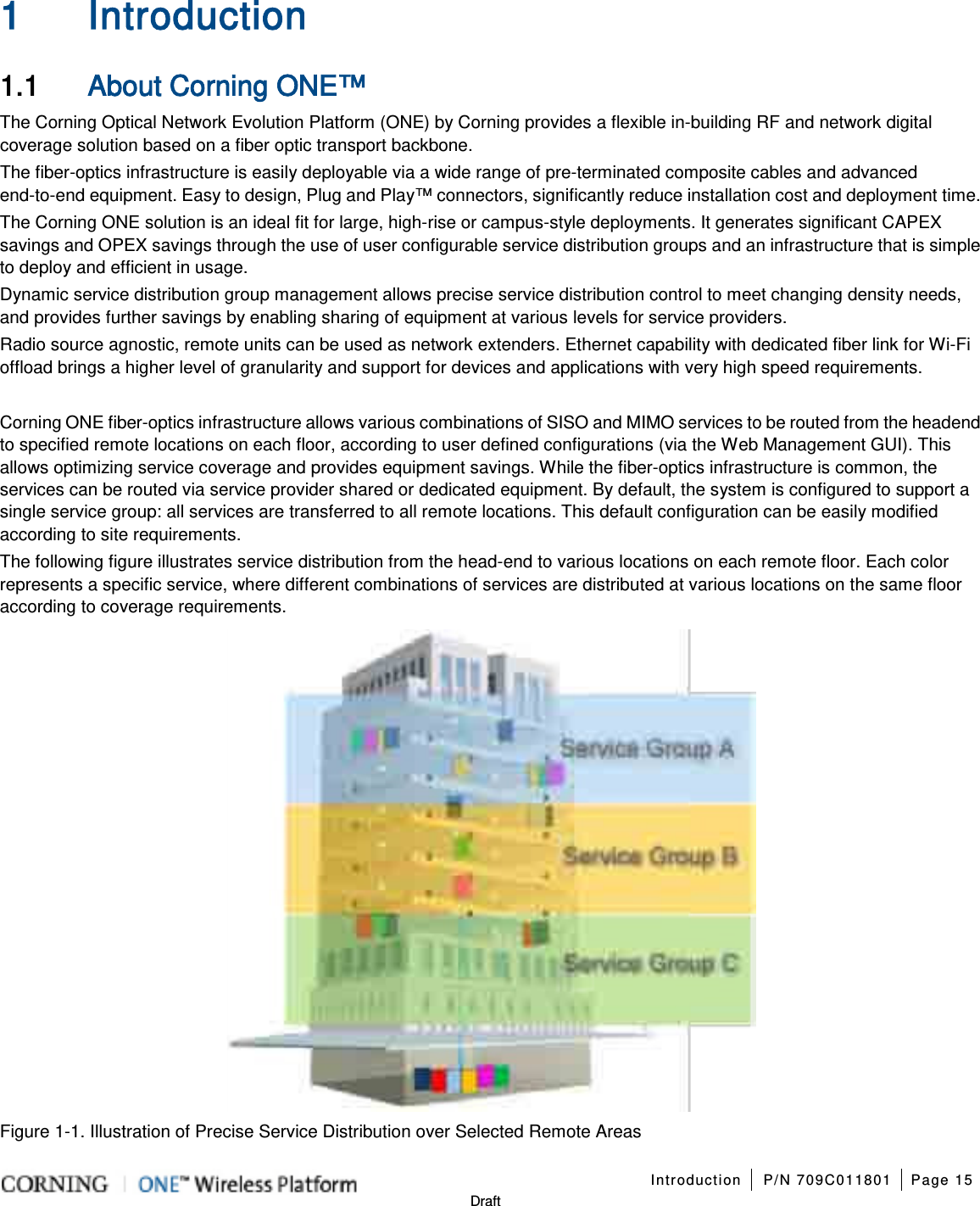
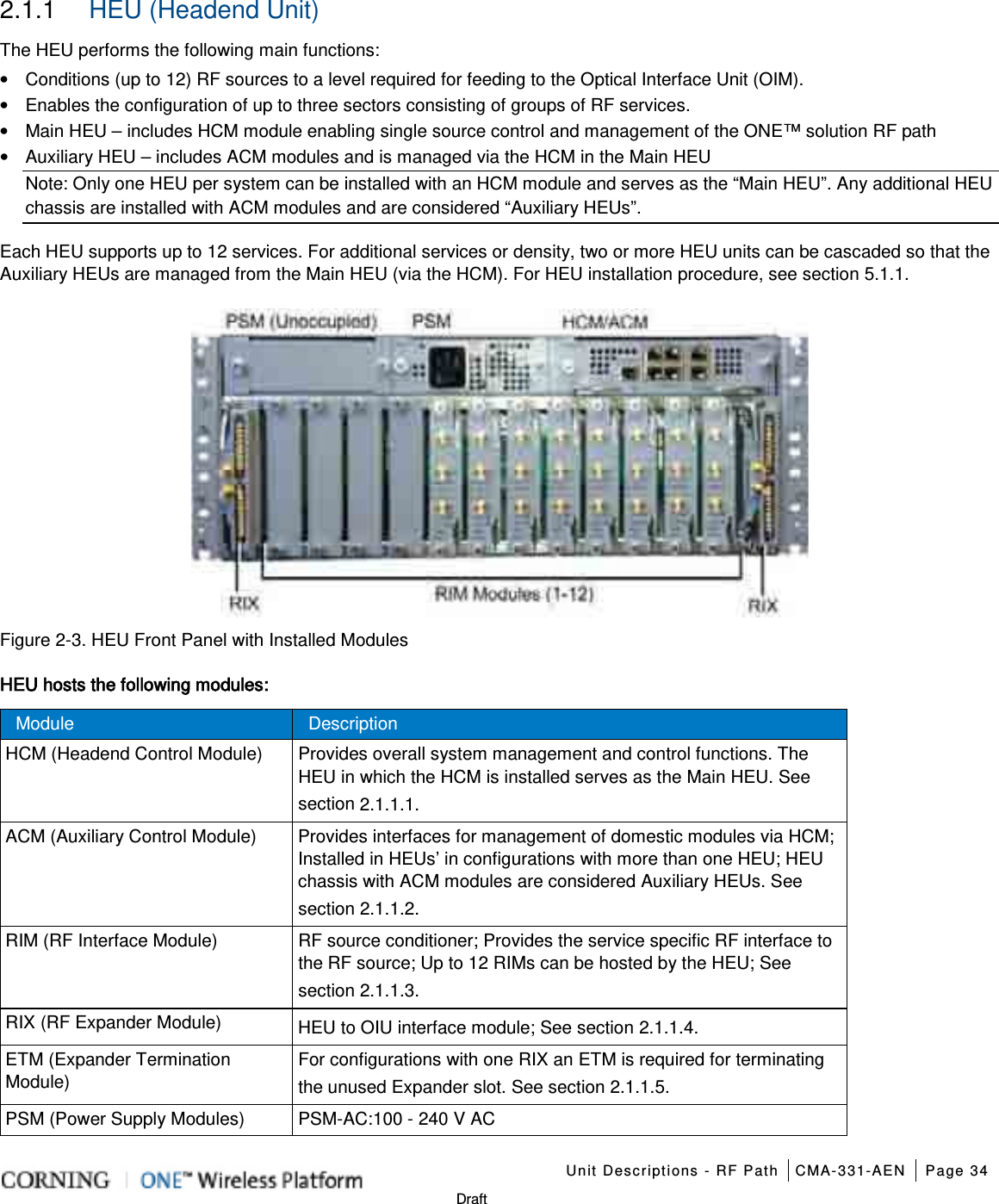
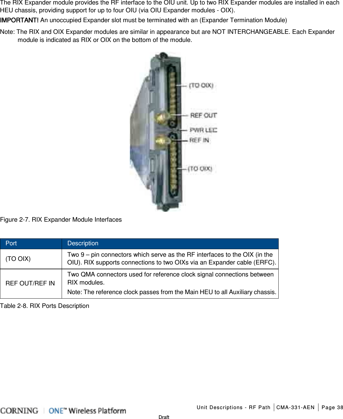
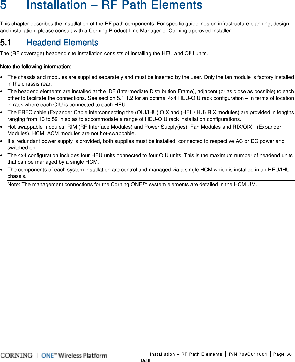
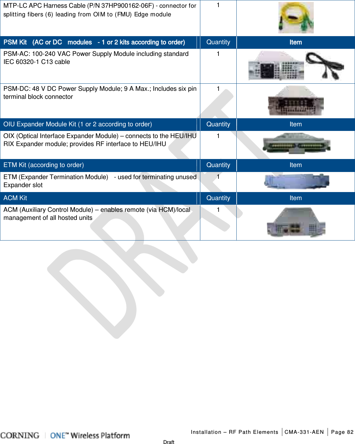
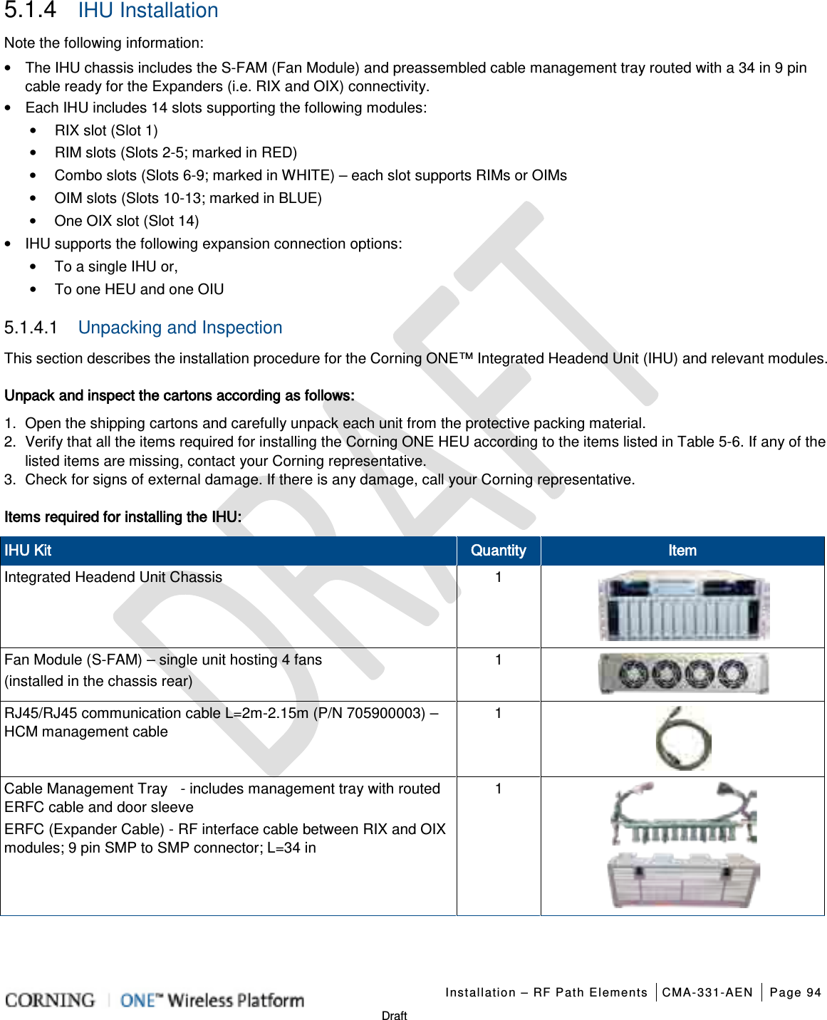
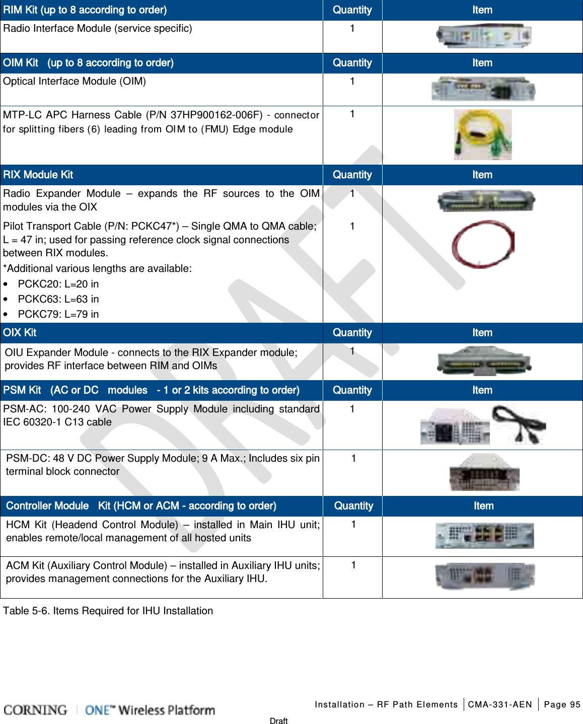
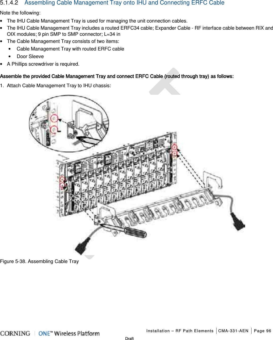
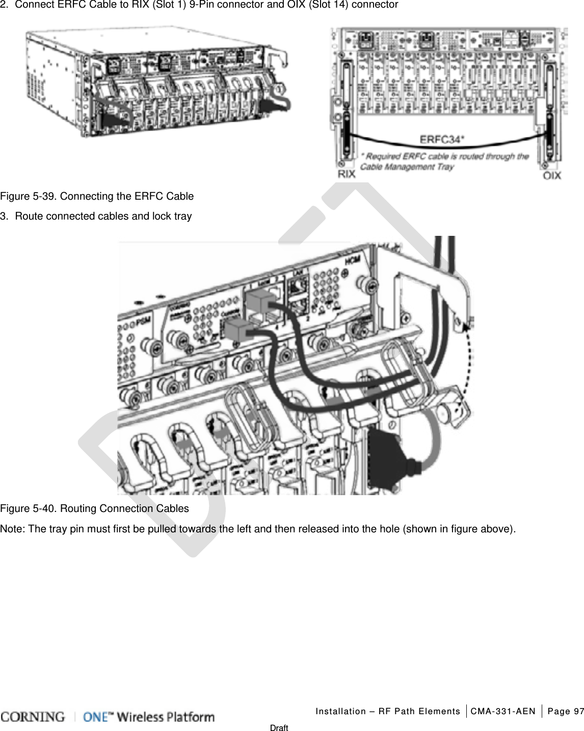
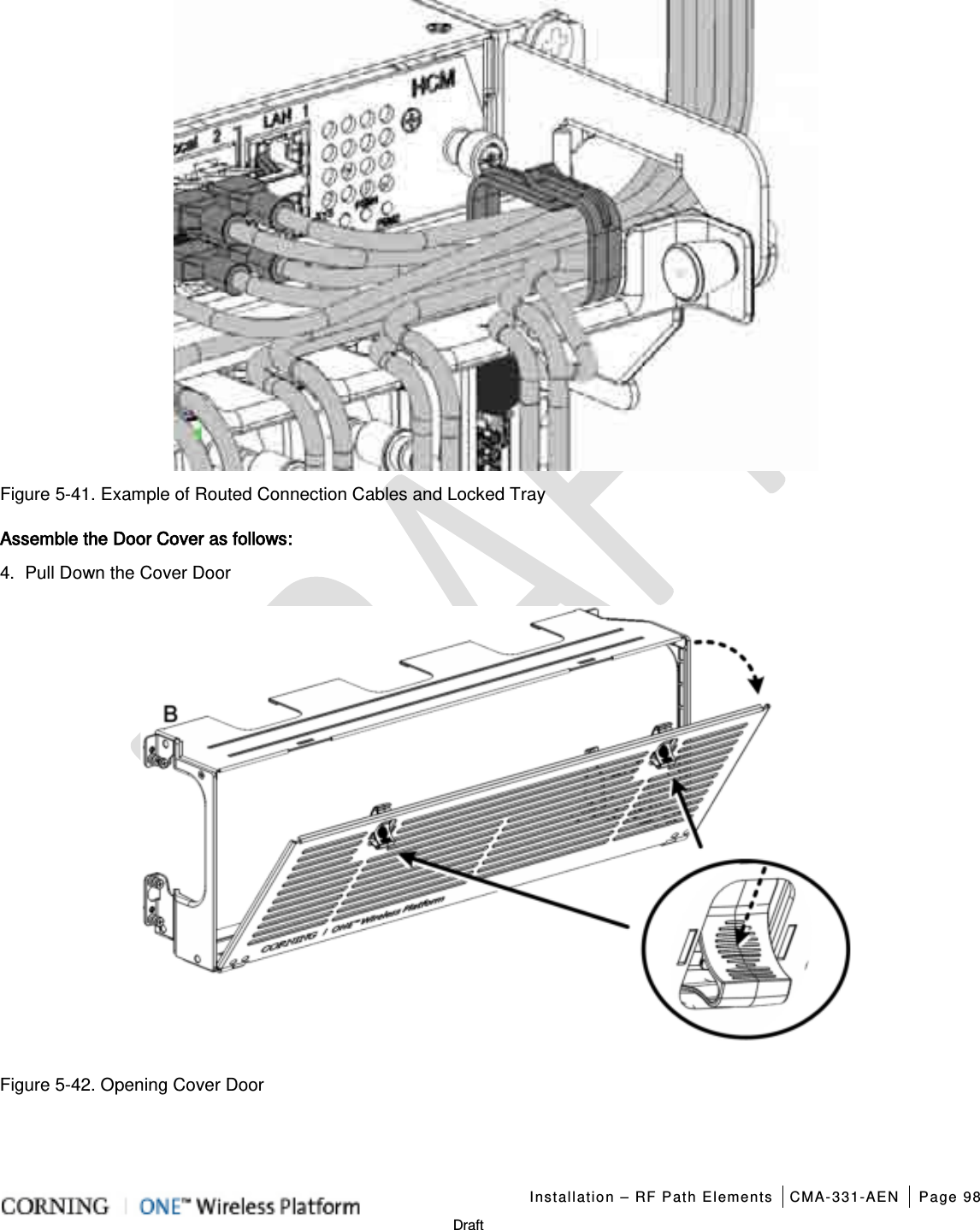
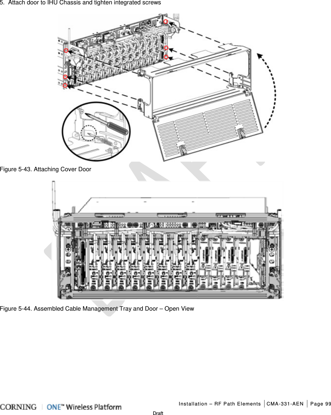
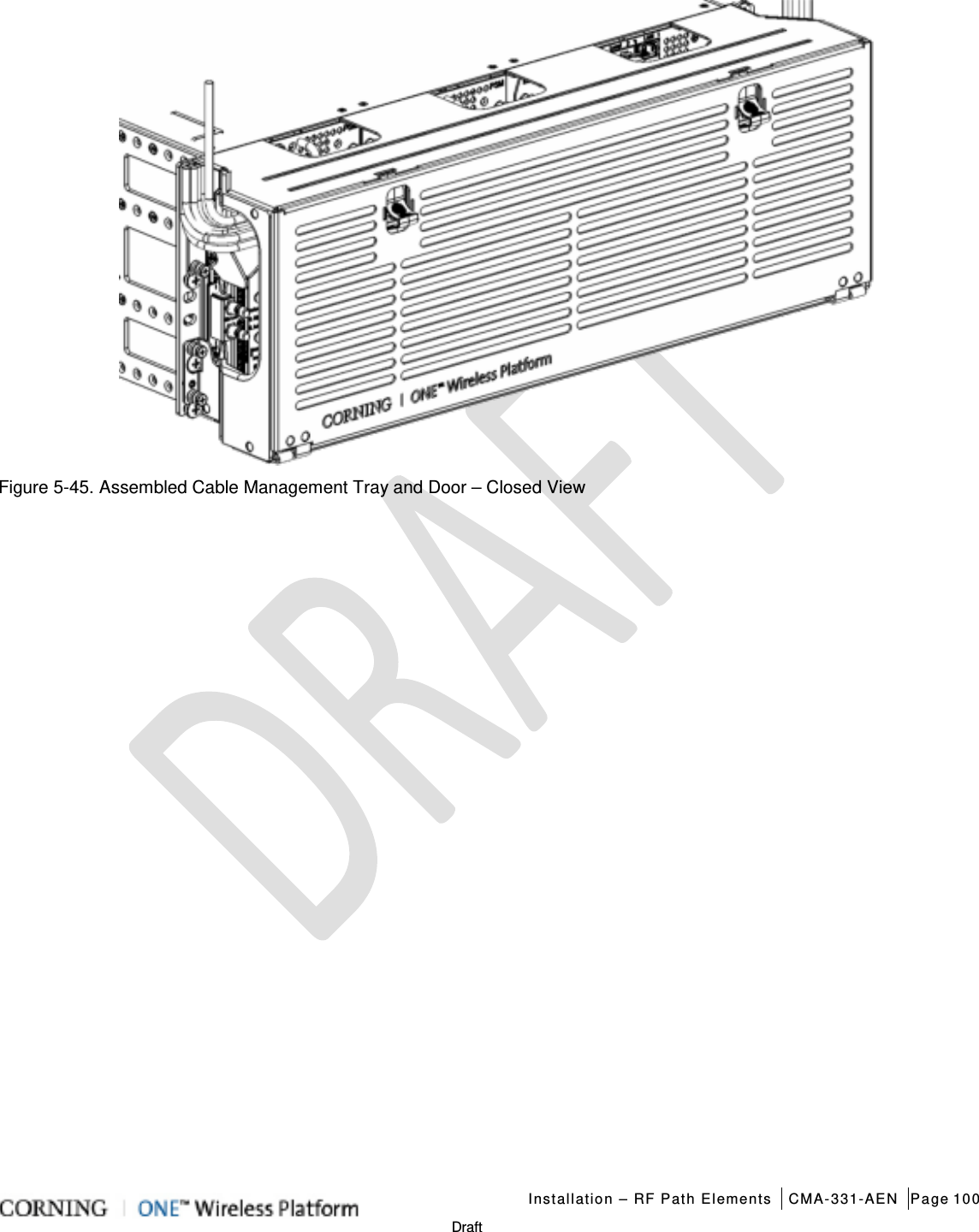
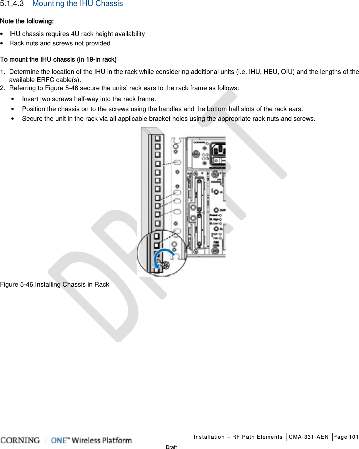
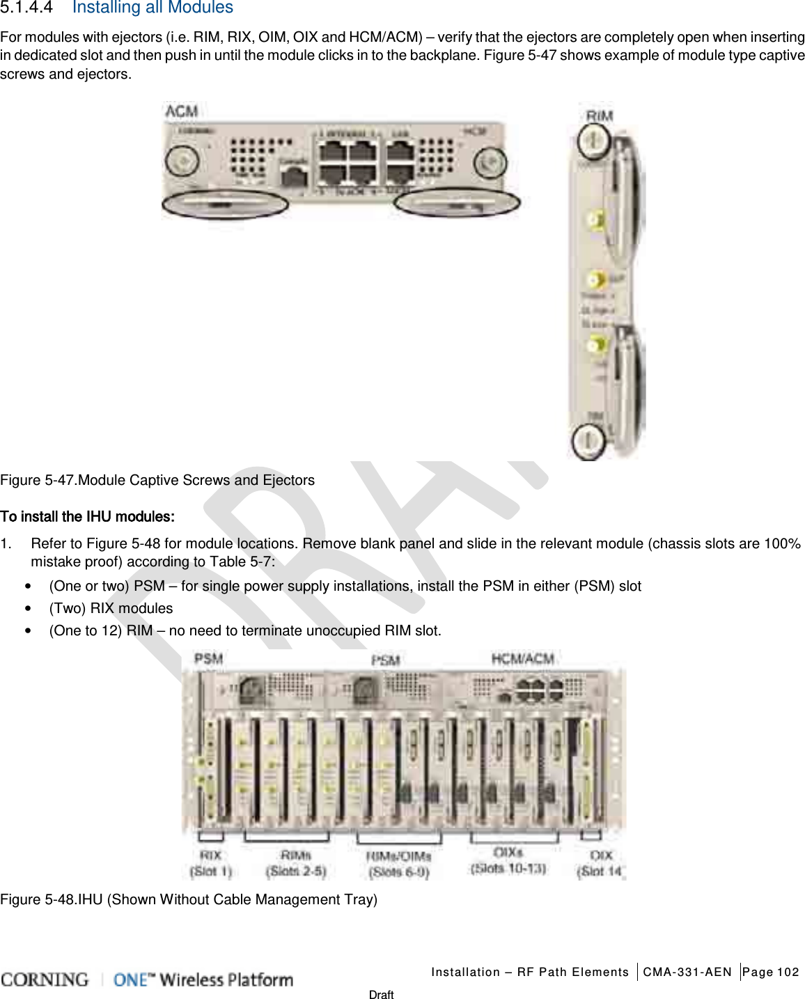
![CMA-331-AEN Page 173 Draft Optical Interface Unit (OIU) (continued) ETM (See ETM in HEU section for description) ACM (See ACM in HEU section for interfaces) PSM-AC (See PSM-AC in HEU section for interfaces) Power Consumption (Full Chassis): 300 W PSM-DC (See PSM-DC in HEU section for interfaces) Power Consumption (Full Chassis): 300 W Physical Characteristics (Chassis + Modules) Mounting: Rack-mount – 19 in and 4U Dimensions ( H x W x D): Chassis: 7 x 17.3 x 18.95 in (177.8 x 440 x 481.7 mm) Cable Management Tray: 6.96 x 20.02 x 4.35 in (176.9 x 508.6 x 110.6 mm) Weight: Chassis : Per OIM: Per OIX: ACM: PSM: 37 lbs (16.8 kg) 1.5 lbs (0.7 kg) 1.54 lbs (0.7 kg) 2.2 lbs (1.0 kg) 1.98 lbs (0.9 kg) Integrated Headend Unit (IHU) IHU will host the following modules: 1. RIX - Radio Interface Expander; RF interface to OIX module 2. RIM - Radio Interface Module; RF source conditioner. Up to eight (four in RIM slots [2-5] and four in combo slots [6-9]) RIMs can be hosted by the IHU 3. OIM- Optical Interface Modules; converts the RF to three optical link Up to eight (four in OIM slots [10-13] and four in combo slots [6-9]) 4. OIX- Optical Interface Expander; OIU to IHU interface Module. 5. HCM- Headend Control Module; overall system management module 6. ACM – Auxiliary Control Module; provides interfaces for management of IHU modules via HCM; installed in IHUs’ in configurations with more than one headend unit (i.e. HEU/IHU) 7. PSM- Power Supply Module; AC or DC power supply 14. ERFC – RF interface cable, 9-PIN; L= 34 in (*routed in provided Cable Management Tray) RIM (See RIM in HEU section for description and interfaces) RIX (See RIX in HEU section for description and interfaces) OIM (See OIM in HEU section for description and interfaces) OIX (See OIX in HEU section for description and interfaces) HCM (See HCM in HEU section for description and interfaces) ACM (See ACM in HEU section for description and interfaces) Cable Management tray with Routed ERFC Cable*](https://usermanual.wiki/Corning-Optical-Communication/1RAU5/User-Guide-2485046-Page-173.png)