Corning Optical Communication 1RAU5X ONE Optical Network Evolution DAS RAU-5x Remote Antenna Unit User Manual
Corning Optical Communication Wireless ONE Optical Network Evolution DAS RAU-5x Remote Antenna Unit Users Manual
UserManual.wiki
>
Corning Optical Communication
>
1RAU5X User Manual
Users Manual
Navigation menu
Upload a User Manual
Namespaces
Wiki Guide
HTML
PDF
Info
Views
User Manual
Discussion / Help
Navigation
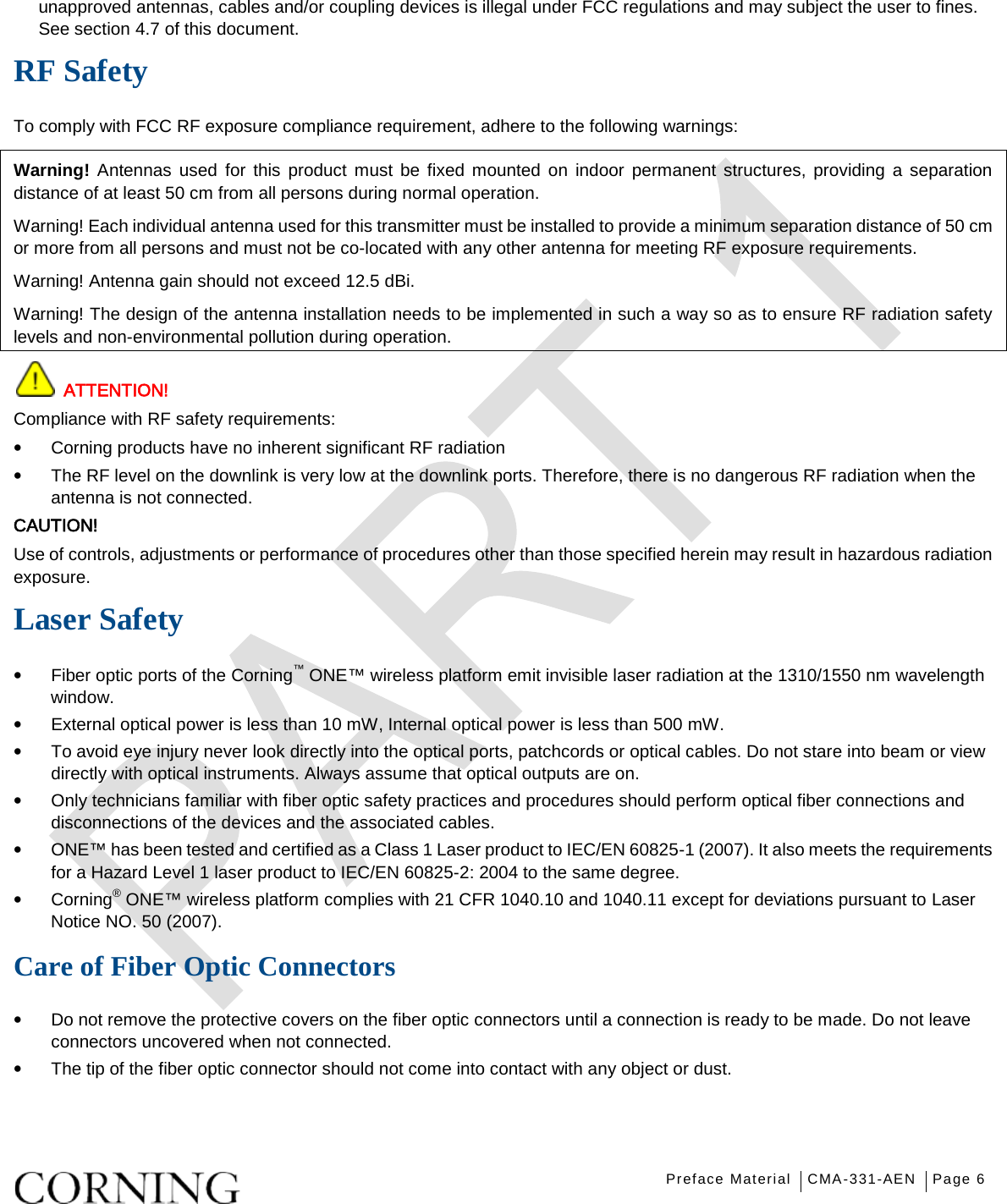
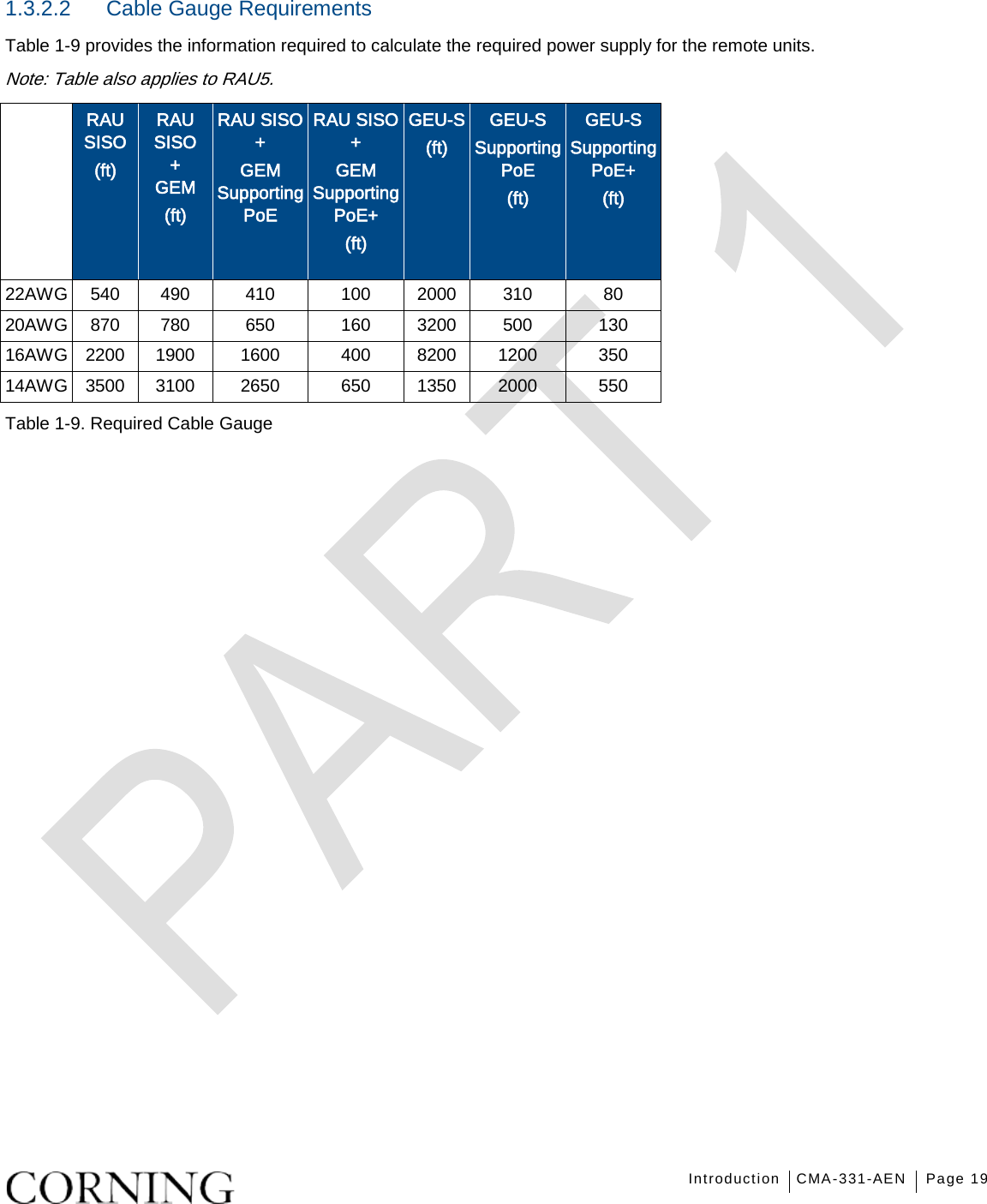
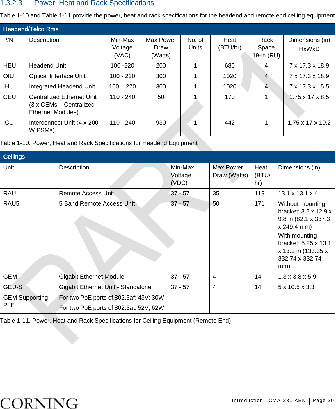
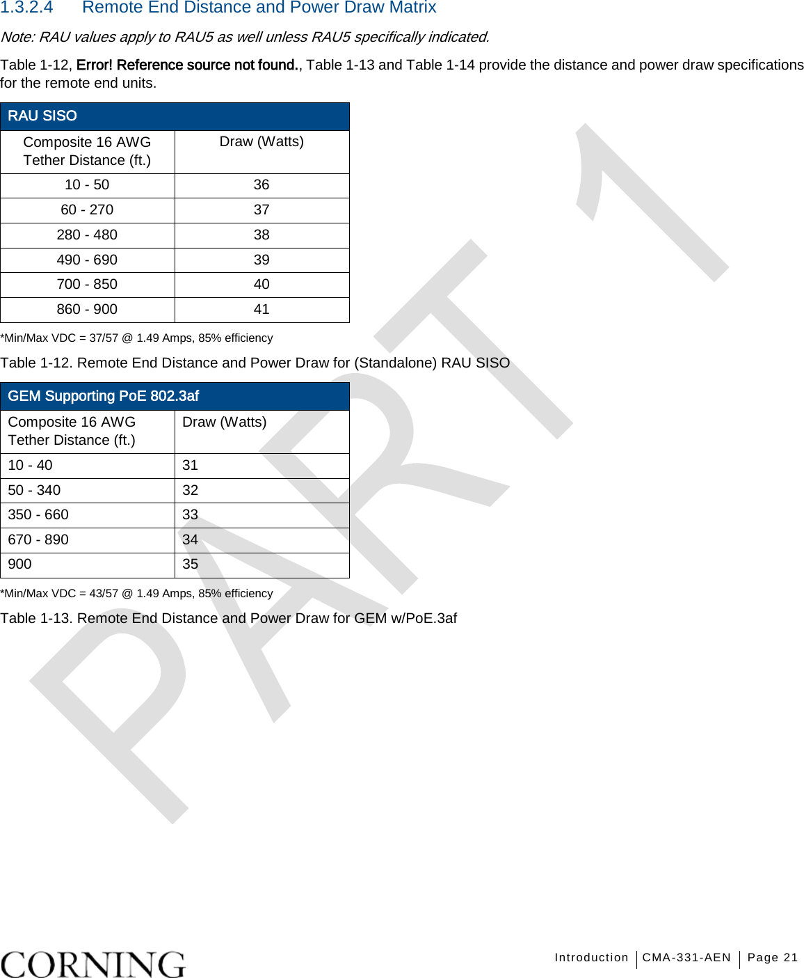
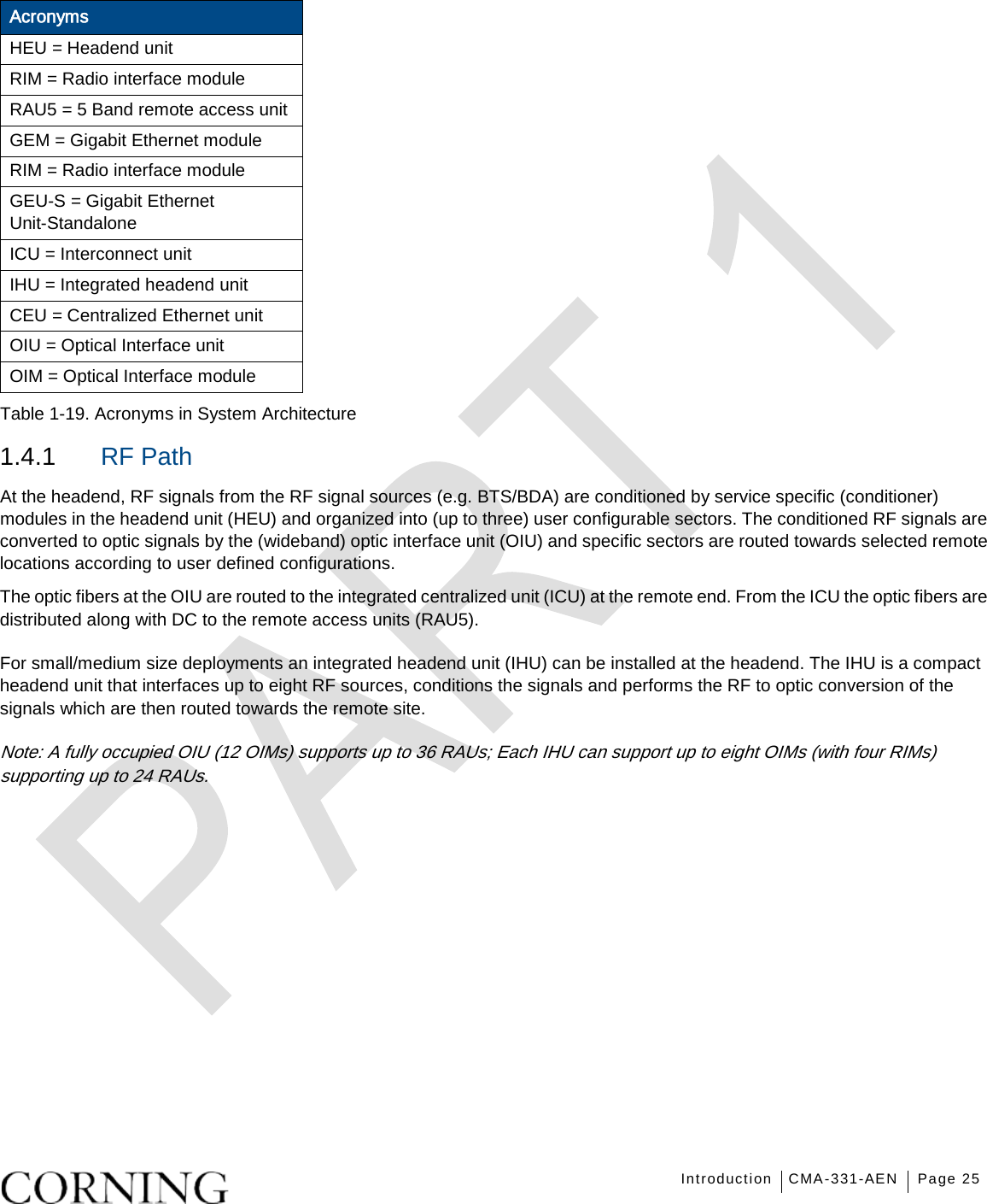
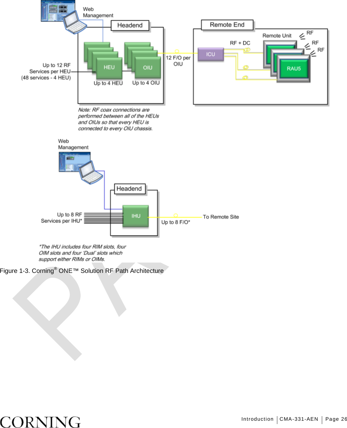
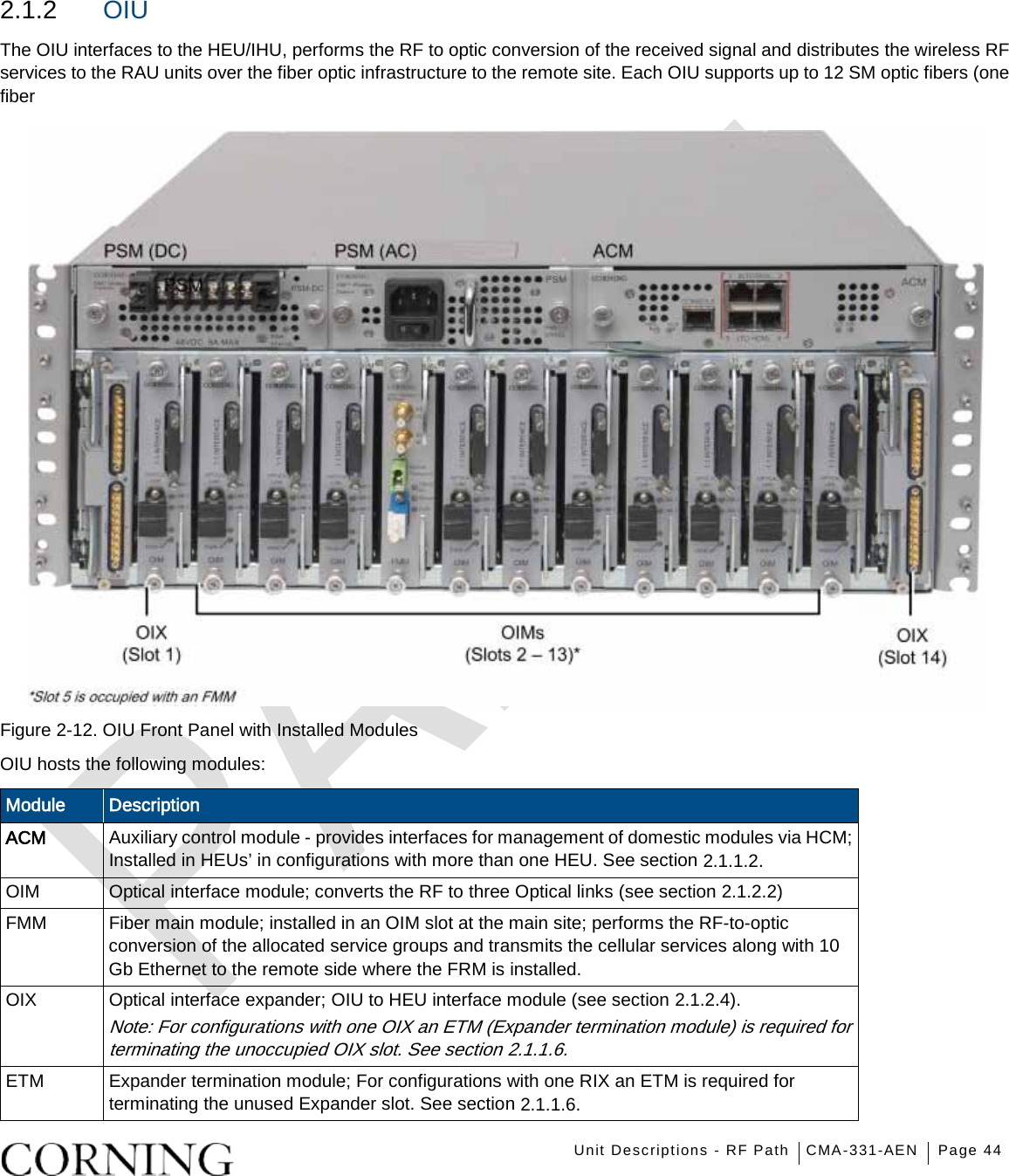
![Introduction CMA-331-AEN Page 22 GEM Supporting PoE 802.3at Composite 16 AWG Tether Distance (ft.) Draw (Watts) Composite 16 AWG Tether Distance (ft.) Draw (Watts) 10 - 80 64 590 - 620 73 90 - 170 65 630 - 670 74 180 - 230 66 680 - 710 75 240 - 300 67 720 – 750 76 310 - 370 68 760 – 790 77 380 - 420 69 800 - 820 78 430 - 470 70 830 - 850 79 480 - 530 71 860 - 890 80 540 - 580 72 900 81 *Min/Max VDC = 52/57 @ 1.49 Amps, 85% efficiency Table 1-14. Remote End Distance and Power Draw for GEM w/PoE.3at 1.3.3 Dimensions and Weight of Units Table 1-15, Table 1-16 and Table 1-17 describe the physical specifications of the Corning® ONE™ headend and remote end units. Note: Refer to MRU datasheet for MRU physical dimensions and weight. Unit Dimensions (H x W x D) Weight: lbs [kg] HEU 7 x 17.3 x 18.95 in (177.8 x 440 x 481.7 mm) Chassis: 37 lbs (16.8 kg) Per RIM: 1.9 lbs (0.9 kg) Per RIX: 1.54 lbs (0.7 kg) Per FRM: 2.42 lbs (1.1 kg) HCM: 2.2 lbs (1.0 kg) PSM: 1.98 lbs (0.9 kg) OIU 7 x 17.3 x 18.95 in [177.8 x 440 x 481.7 mm] Chassis: : 37 lbs (16.8 kg) Per OIM: 1.5 lb (0.7 kg) Per OIX: 1.54 lb (0.7 kg) Per FMM: 2.42 lbs (1.1 kg) ACM: 2.2 lb (1.0 kg) PSM: 1.98 lb (0.9 kg) IHU 7 x 17.3 x 15.5 in [177.8 x 440 x 394 mm] Chassis: 30 lbs (14 kg) Per RIM: 1.9 lbs (0.9 kg) Per RIX: 1.54 lbs (0.7 kg) Per OIM: 1.5 lb (0.7 kg) Per OIX: 1.54 lb (0.7 kg) ACM: 2.2 lb (1.0 kg) PSM: 1.98 lb (0.9 kg) Table 1-15. RF Path Headend Units](https://usermanual.wiki/Corning-Optical-Communication/1RAU5X/User-Guide-2905791-Page-22.png)
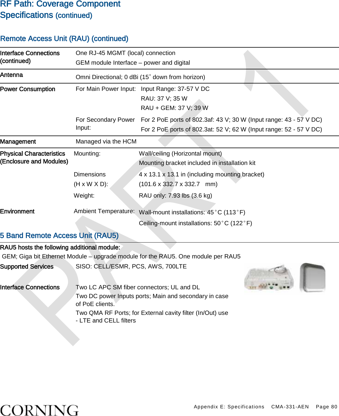
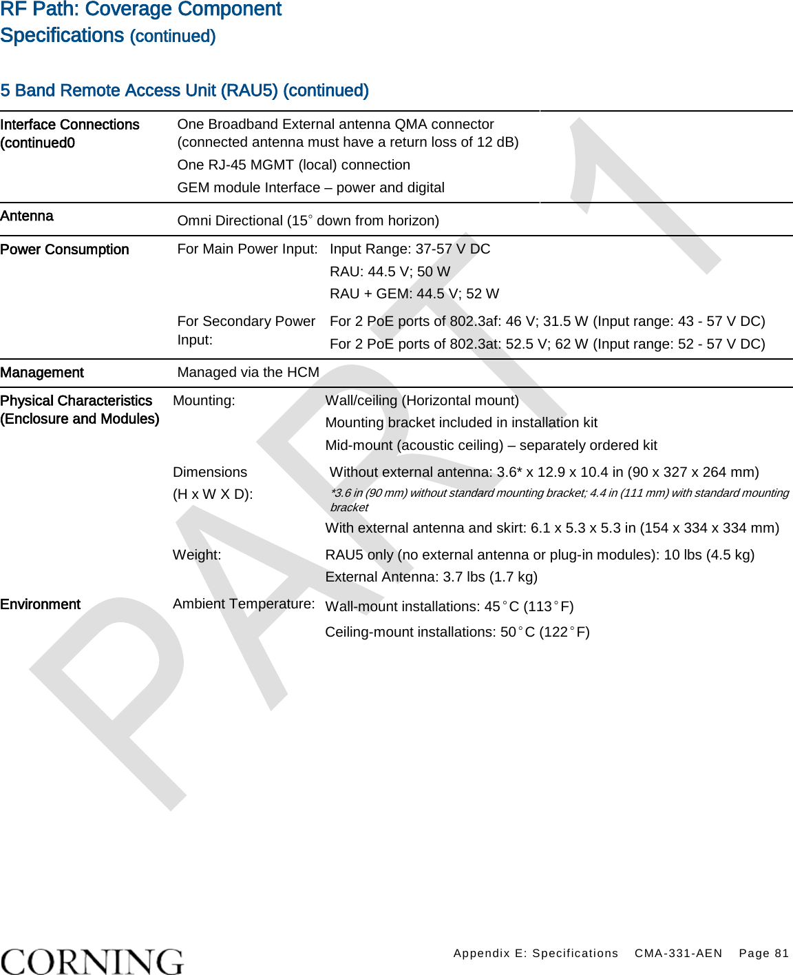
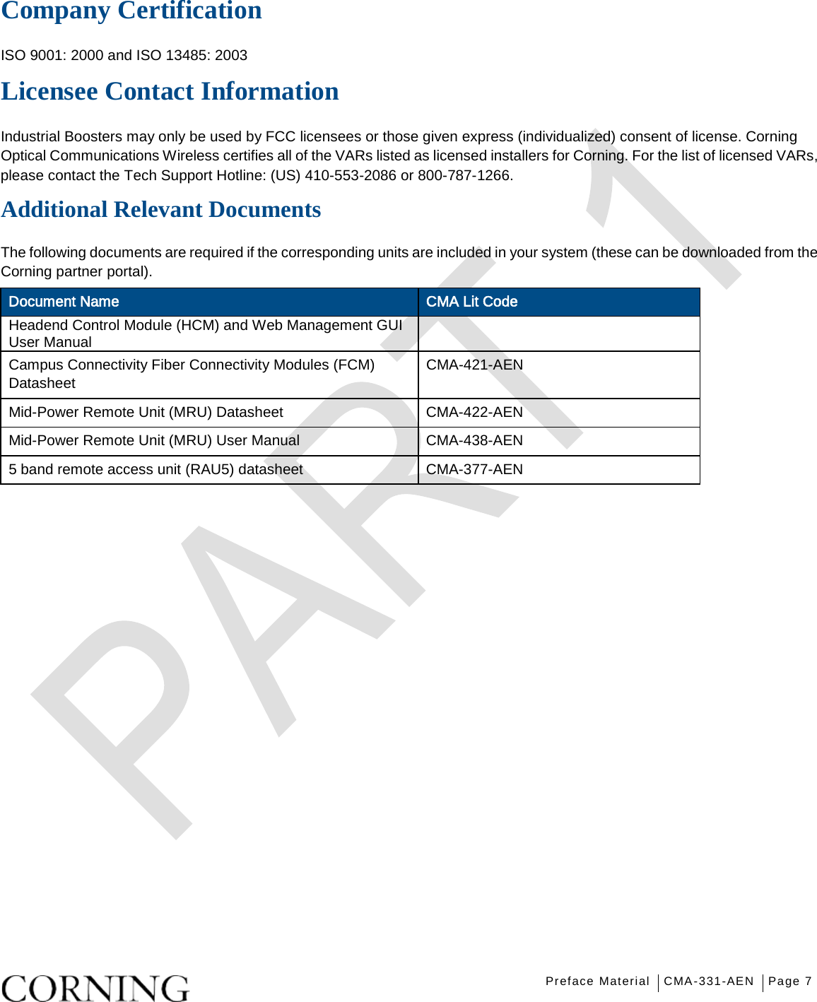
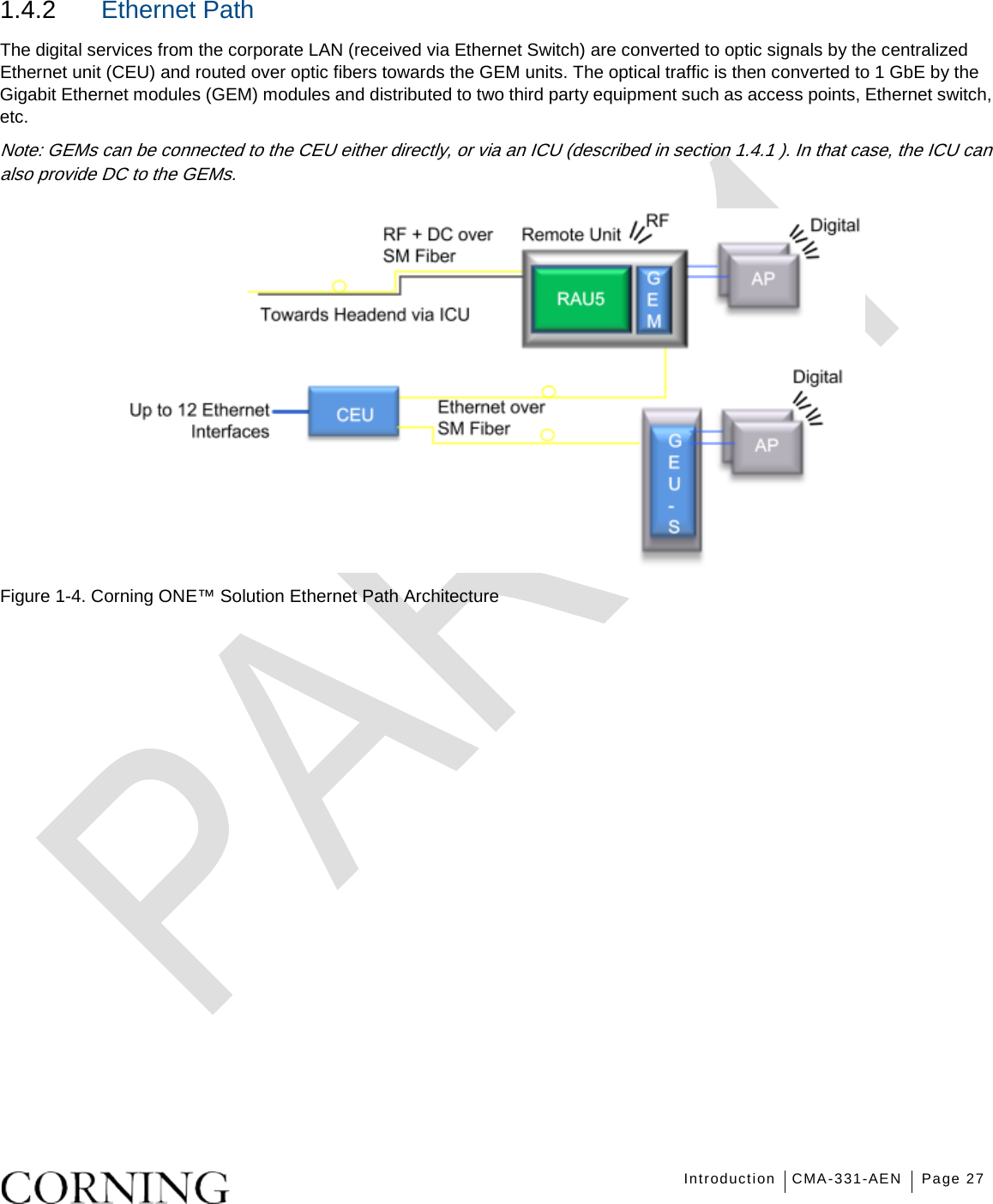
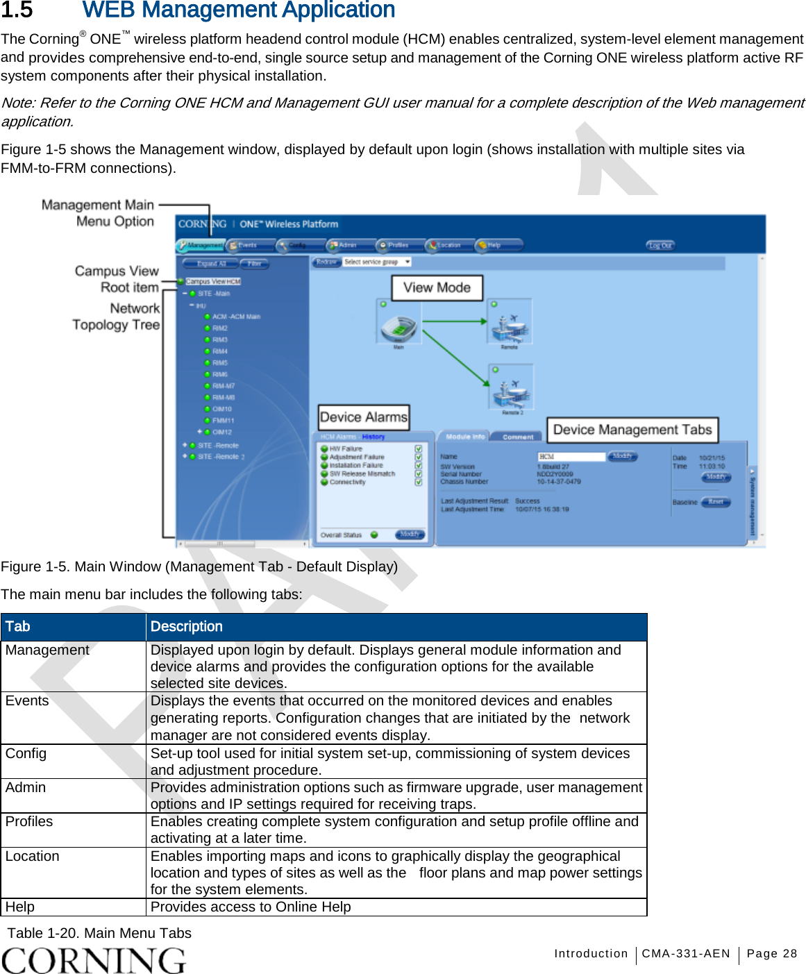
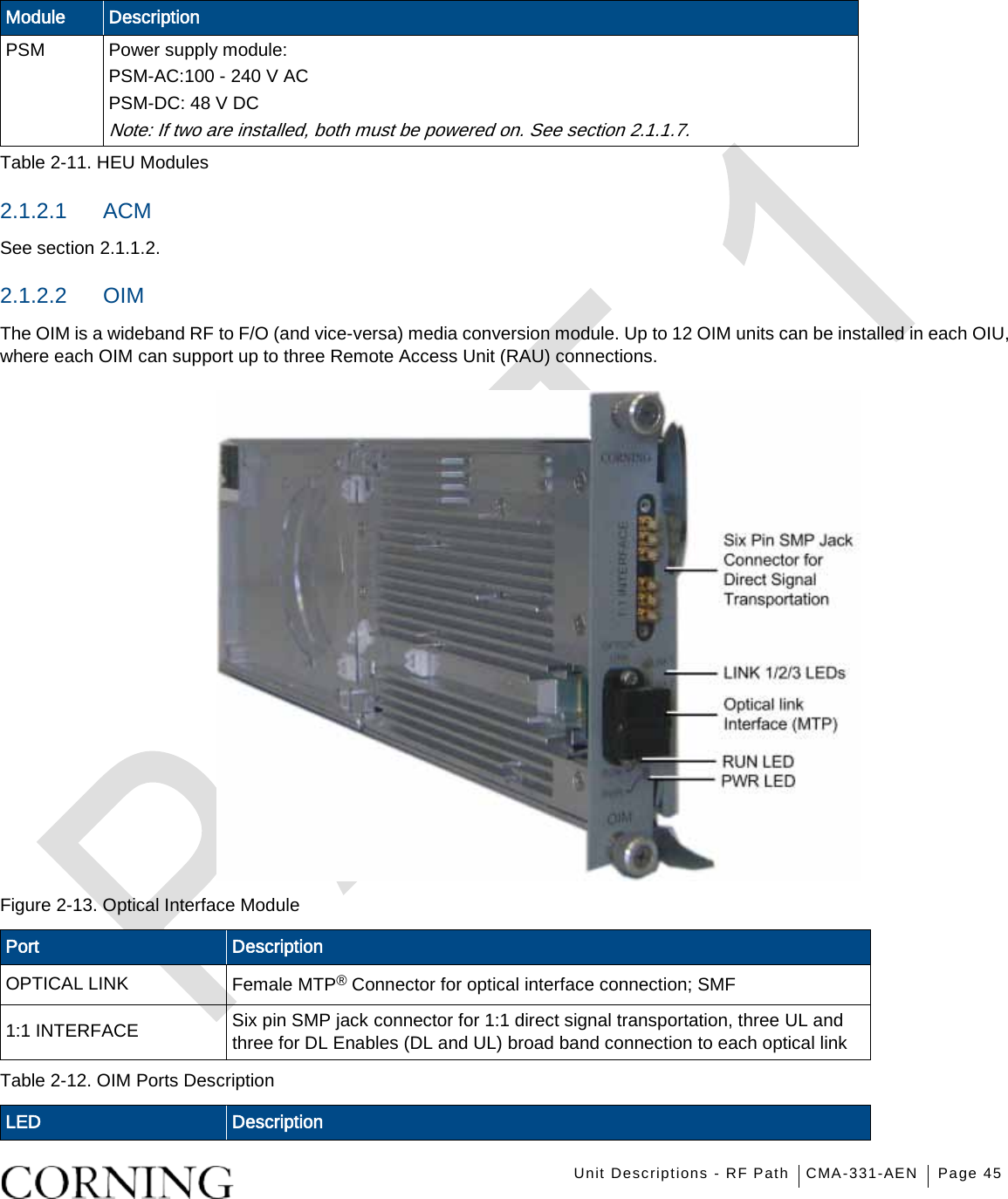
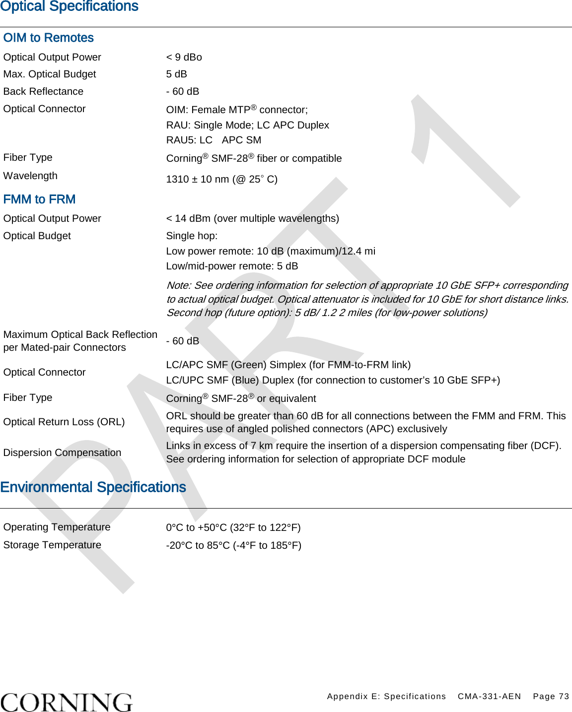
![Introduction CMA-331-AEN Page 23 Unit Dimensions (H x W x D) Weight: lbs [kg] ICU 1.74 x 17 x 19.2 in (44.4 x 431.8 x 11.96 mm) 5.5 lb (2.5 kg) – without PSM RAU (including mounting bracket) 13.1 x 13.1 x 4 in (332.7 x 332.7 x 101.6 mm) RAU only = 7.93 lb (3.6 kg); RAU5 (including mounting bracket) Without external antenna: 3.6* x 12.9 x 10.4 in (90 x 327 x 264 mm) *3.6 in (90 mm) without standard mounting bracket; 4.4 in (111 mm) with standard mounting bracket With external antenna and skirt: 6.1 x 5.3 x 5.3 in (154 x 334 x 334 mm) RAU5 only: 10 lbs (4.5 kg) Table 1-16. RF Path Remote Units Unit Dimensions (H x W x D) Weight: lbs (kg) CEU: CEU 1.71 x 17 x 8.5 in (43.65 x 431.8 x 216 mm) (with mounting ears: W = 19 in/482.8 mm) 7.55 lb (3.4 kg) CEM 1.41 x 3.94 x 7.68 in (36 x 100.14 x 195.14 mm) 1.44 lb (0.65 kg) GEM 1.28 x 3.79 x 5.95 in (32.7 x 96.3 x 151.3 mm) 1.1 lb (0.5 kg) GEU-S 5.01 x 10.51 x 3.26 in (including mounting bracket) (127.5 x 267 x 83 mm) 2.64 lb (1.2 kg) Table 1-17. Ethernet Path Units 1.3.4 Optical Specifications Parameter Specification Optical Output Power < 9 dBo Max. Optical Budget 5 dB Optical Connector OIM: MTP® connector RAU: LC APC SM Fiber Type Corning® SMF-28® or Compatible Wavelength 1310±10 nm (Standard) Table 1-18. Optical Specifications](https://usermanual.wiki/Corning-Optical-Communication/1RAU5X/User-Guide-2905791-Page-23.png)


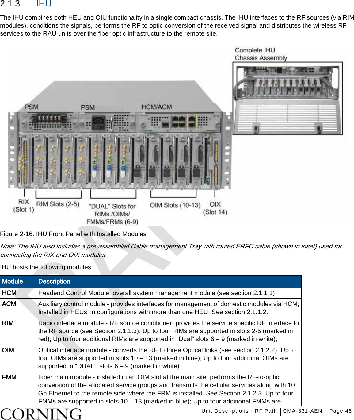


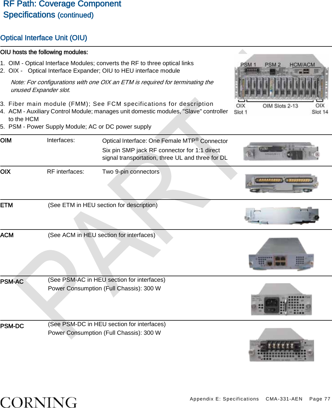
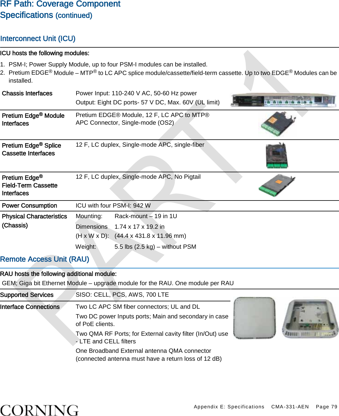
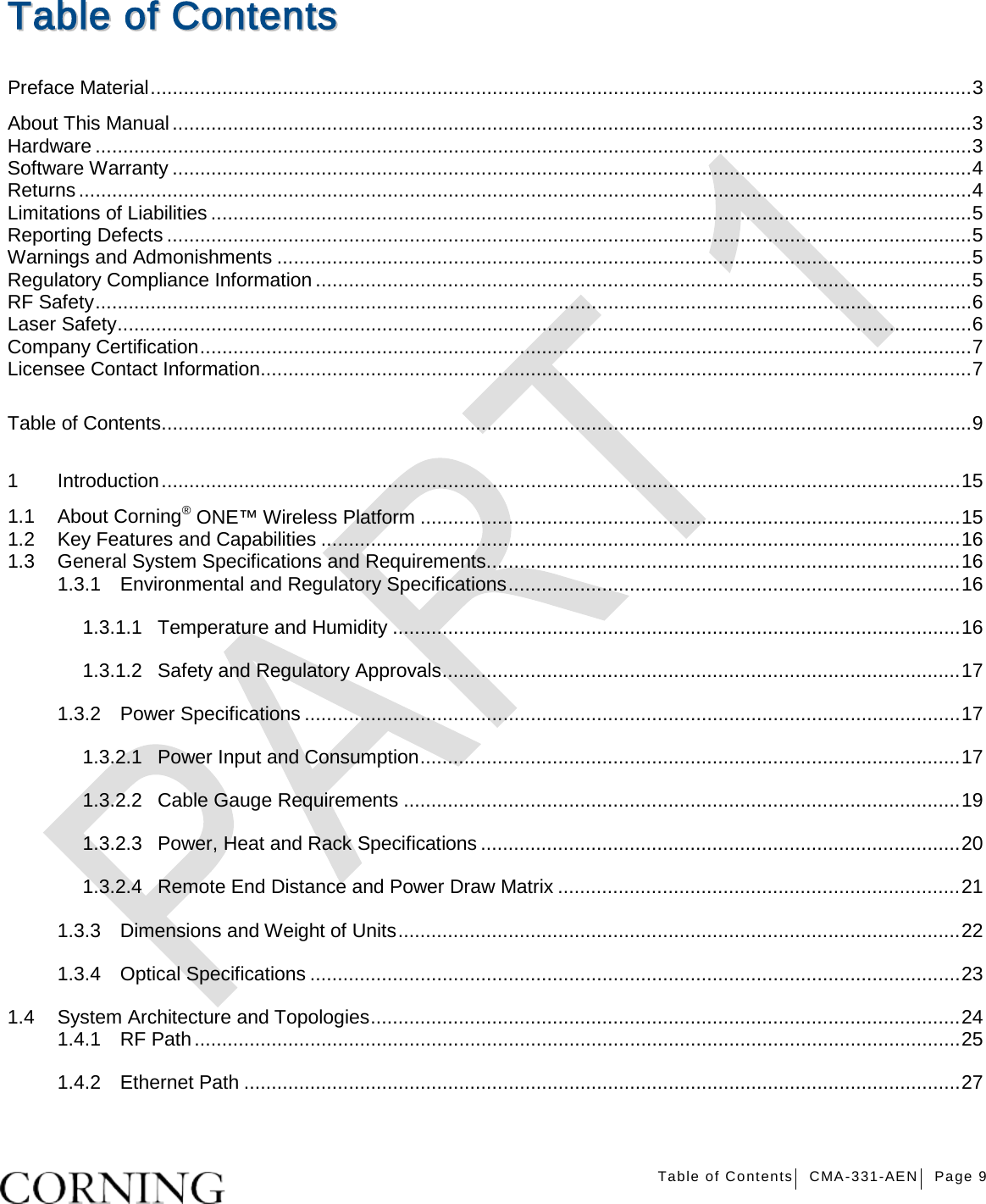
![Appendix E: Specifications CMA-331-AEN Page 78 RF Path: Coverage Component Specifications (continued) Optical Interface Unit (OIU) (continued) Physical Characteristics (Chassis + Modules) Mounting: Rack-mount – 19 in and 4U Dimensions ( H x W x D): Chassis: 7 x 17.3 x 18.95 in (177.8 x 440 x 481.7 mm) Cable Management Tray: 6.96 x 20.02 x 4.35 in (176.9 x 508.6 x 110.6 mm) Weight: Chassis : Per OIM: Per OIX: ACM: PSM: 37 lbs (16.8 kg) 1.5 lbs (0.7 kg) 1.54 lbs (0.7 kg) 2.2 lbs (1.0 kg) 1.98 lbs (0.9 kg) Integrated Headend Unit (IHU) IHU will host the following modules: 1. RIX - Radio Interface Expander; RF interface to OIX module 2. RIM - Radio Interface Module; RF source conditioner. Up to eight (four in RIM slots [2-5] and four in combo slots [6-9]) RIMs can be hosted by the IHU 3. OIM- Optical Interface Modules; converts the RF to three optical link Up to eight (four in OIM slots [10-13] and four in combo slots [6-9]) 4. OIX- Optical Interface Expander; OIU to IHU interface Module. 5. HCM- Headend Control Module; overall system management module 6. ACM – Auxiliary Control Module; provides interfaces for management of IHU modules via HCM; installed in IHUs’ in configurations with more than one headend unit (i.e. HEU/IHU) 7. PSM- Power Supply Module; AC or DC power supply; IHU Max Power Consumption (Full Chassis): 300 W 6. ERFC – RF interface cable, 9-PIN; L= 34 in (routed in provided Cable Management Tray) Note: Refer to HEU specifications for descriptions of RIX, RIM, HCM /ACM and PSM modules and refer to OIU specifications for descriptions of OIM and OIX modules Physical Characteristics (Chassis and Modules) Mounting: Rack-mount – 19 in , 4U Dimensions (H x W X D): Chassis: 7 x 17.3 x 15.5 in (177.8 x 440 x 394 mm) Weight: Chassis: 30 lbs (14 kg) Per RIM: 1.9 lbs (0.9 kg) Per OIM: 1.5 lbs (0.7kg) RIX: 1.54 lbs (0.7 kg OIX: 1.54 lbs (0.7 kg) ACM: 2.2 lbs (1.0 kg) PSM: 1.98 lbs (0.9 kg)](https://usermanual.wiki/Corning-Optical-Communication/1RAU5X/User-Guide-2905791-Page-78.png)