Corning Optical Communication 1RXUN Remote Extender Unit RXU2325 TDD/WCS User Manual ONE Wireless Platform
Corning Optical Communication Wireless Remote Extender Unit RXU2325 TDD/WCS ONE Wireless Platform
User Manual

5 Band Remote Access Unit
(RAU5/RAU5x)
User Manual
Corning Optical Communications User Manual I CMA-482-AEN I Page 2
Warranties
Hardware Warranty
Corning Optical Communications LLC (“Corning”) warrants to the original purchaser (“Customer”) that for the duration of
the warranty period, one (1) year, commencing on the date of shipment of the Hardware, unless otherwise agreed in writing
by Corning (the “Hardware Warranty Period”), the Hardware furnished by Corning shall be free in all material respects from
defects in material and workmanship, and shall conform to the applicable portions of the Specifications, as defined below
(the “Hardware Warranty”). If notified by Customer of any such defects in material or workmanship or nonconformity with
applicable portions of the Specifications within the Hardware Warranty Period, Corning shall promptly, at its own election
and expense, repair or replace any such Hardware proven to be defective under the terms of this Hardware Warranty. Such
repair or replacement shall be Customer’s sole remedy and Corning’s sole obligation in the event this Hardware Warranty is
invoked. If any components comprising a part of the Hardware are replaced or repaired during the Hardware Warranty Period,
the Hardware Warranty Period for such repaired or replaced components shall extend to the longer of (i) the balance of the
Hardware Warranty Period or (ii) three (3) months from the date of repair or replacement. For purposes of this Warranty,
“Specifications” shall mean the specifications and performance standards of the Products as set forth in documents published
by Corning and delivered to Customer which contain technical specifications or performance standards for the Products.
If Customer invokes this Hardware Warranty, it shall notify Corning promptly of the claimed defect. Customer will allow Corning
to inspect the Hardware at Customer’s location, or to return the Hardware to Corning closest repair facility. For Hardware
returned to Corning repair facility, Customer shall be responsible for payment of all transportation and freight costs (including
insurance) to Corning’ repair facility, and Corning shall be responsible for all transportation and freight costs (including
insurance) incurred in connection with the shipment of such Hardware to other repair facilities of Corning and/or its return to
Customer.
Notwithstanding the foregoing, in no event will Corning be liable for damage to Products resulting from improper handling during
or after shipment, misuse, neglect, improper installation, operation or repair (other than by authorized Corning personnel),
alteration, accident, or for any other cause not attributable to defects in materials or workmanship on the part of Corning.
Corning shall not reimburse or make any allowance to Customer for any labor charges incurred by Customer for replacement or
repair of any goods unless such charges are authorized in advance in writing by Corning.
Software Warranty
Corning Optical Communications LLC (“Corning”) warrants to the original purchaser (“Customer”) that for the duration of the
warranty period, one (1) year, commencing on the date of shipment of the Software, unless otherwise agreed in writing by
Corning (the “Software Warranty Period”), the Software shall conform with, and perform the functions set forth in the
Specifications, and shall be free from defects in material or workmanship (the “Software Warranty”). In the event the Software is
proven to be defective under the terms of this Software Warranty, Corning shall correct such defects or failure and ensure that
the Software conforms with, and performs the functions set forth in, the Specifications. Customer will allow Corning to inspect
the Software at Customer’s location or to return it to Corning’s closest repair facility.
Notwithstanding the foregoing, Corning shall have no obligation under the Software Warranty if the Software is modified or used
with hardware or software not supplied or approved by Corning or if the Software is subject to abuse, improper installation or
application, accident, electrical or environmental over-stress, negligence in use, storage, transportation or handling.
Third-party software distributed with the Software may carry certain warranties which, to the maximum extent allowed by law,
Corning hereby assigns, transfers and otherwise conveys to Customer, provided, however, that Corning itself provides no
warranty of any kind, express, implied, statutory or otherwise, for any third-party software provided hereunder.
Corning does not warrant any hardware, software or services not provided by Corning.
THIS WARRANTY IS THE ONLY WARRANTY MADE BY CORNING AND IS IN LIEU OF ALL OTHER WARRANTIES,
EXPRESS OR IMPLIED INCLUDING, BUT NOT LIMITED TO, THE IMPLIED WARRANTIES OF MERCHANTABILITY AND
FITNESS FOR A PARTICULAR PURPOSE. CORNING SHALL NOT BE LIABLE FOR ANY OTHER DAMAGE INCLUDING,
BUT NOT LIMITED TO, INDIRECT, SPECIAL OR CONSEQUENTIAL DAMAGES ARISING OUT OF OR
Corning Optical Communications User Manual I CMA-482-AEN I Page 3
IN CONNECTION WITH FURNISHING OF GOODS, PARTS AND SERVICE HEREUNDER, OR THE PERFORMANCE, USE
OF, OR INABILITY TO USE THE GOODS, PARTS AND SERVICE.
CORNING SALES AGENTS OR REPRESENTATIVES ARE NOT AUTHORIZED TO MAKE COMMITMENTS ON
WARRANTY RETURNS.
Returns
In the event that it is necessary to return any product against above warranty, the following procedure shall be followed:
1. Return authorization is to be received from Corning prior to returning any unit. Advise Corning of the model, Serial number,
and discrepancy. The unit may then be forwarded to Corning, transportation prepaid. Devices returned collect or without
authorization may not be accepted.
2. Prior to repair, Corning will advise the customer of our test results and any charges for repairing customer-caused problems
or out-of-warranty conditions etc.
3. Repaired products are warranted for the balance of the original warranty period, or at least 90 days from date of shipment.

Corning Optical Communications User Manual I CMA-482-AEN I Page 4
Limitations of Liabilities
Corning’s liability on any claim, of any kind, including negligence for any loss or damage arising from, connected with, or
resulting from the purchase order, contract, quotation, or from the performance or breach thereof, or from the design,
manufacture, sale, delivery, installation, inspection, operation or use of any equipment covered by or furnished under this
contact, shall in no case exceed the purchase price of the device which gives rise to the claim.
Except as expressly provided herein, Corning makes no warranty, expressed or implied, with respect to any goods, parts and
services provided in connection with this agreement including, but not limited to, the implied warranties of merchantability and
fitness for a particular purpose. Corning shall not be liable for any other damage including, but not limited to, indirect, special or
consequential damages arising out of or in connection with furnishing of goods, parts and service hereunder, or the
performance, use of, or inability to use the goods, parts and service.
Reporting Defects
The units were inspected before shipment and found to be free of mechanical and electrical defects. Examine the units for any
damage that may have been caused in transit. If damage is discovered, file a claim with the freight carrier immediately. Notify
Corning as soon as possible in writing.
Note: Keep all packing material until you have completed the inspection
Warnings and Admonishments
There may be situations, particularly for workplace environments near high-powered RF sources, where recommended limits
for safe exposure of human beings to RF energy could be exceeded. In such cases, restrictive measures or actions may be
necessary to ensure the safe use of RF energy.
The equipment has been designed and constructed to prevent, as far as reasonably, practicable danger. Any work activity on or
near equipment involving installation, operation or maintenance must be, as far as reasonably, free from danger.
Where there is a risk of damage to electrical systems involving adverse weather, extreme temperatures, wet, corrosive or dirty
conditions, flammable or explosive atmospheres, the system must be suitably installed to prevent danger.
Equipment provided for the purpose of protecting individuals from electrical risk must be suitable for the purpose and properly
maintained and used. This covers a range of activities including lifting, lowering, pushing, pulling, carrying, moving, holding or
restraining an object, animal or person from the equipment. It also covers activities that require the use of force or effort, such as
pulling a lever, or operating power tools.
Where some of the above mentioned activities are required, the equipment must be handled with care to avoid being damaged.
Observe standard precautions for handling ESD-sensitive devices. Assume that all solid-state electronic devices are
ESD-sensitive. Ensure the use of a grounded wrist strap or equivalent while working with ESD-sensitive devices. Transport,
store, and handle ESD-sensitive devices in static-safe environments.
Regulatory Compliance Information
WARNINGS!
• This is NOT a CONSUMER device. It is designed for installation by FCC LICENCEES and QUALIFIED INSTALLERS. You
MUST have an FCC LICENSE or express consent of an FCC Licensee to operate this device. Unauthorized use may result
in significant forfeiture penalties, including penalties in excess of $100,000 for each continuing violation.
• ANTENNAS: Use only authorized and approved antennas, cables and/or coupling devices! The use of unapproved
antennas, cables or coupling devices could cause damage and may be of violation of FCC regulations. The use of
Corning Optical Communications User Manual I CMA-482-AEN I Page 5
unapproved antennas, cables and/or coupling devices is illegal under FCC regulations and may subject the user to fines.
See section 3.6 of this document.
RF Safety
To comply with FCC RF exposure compliance requirement, adhere to the following warnings:
Warning! Antennas used for this product must be fixed mounted on indoor permanent structures, providing a separation
distance of at least 50 cm from all persons during normal operation.
Warning! Each individual antenna used for this transmitter must be installed to provide a minimum separation distance of 50 cm
or more from all persons and must not be co-located with any other antenna for meeting RF exposure requirements.
Warning! Antenna gain should not exceed 12.5 dBi.
Warning! The design of the antenna installation needs to be implemented in such a way so as to ensure RF radiation safety
levels and non-environmental pollution during operation.
ATTENTION!
Compliance with RF safety requirements:
• Corning products have no inherent significant RF radiation
• The RF level on the downlink is very low at the downlink ports. Therefore, there is no dangerous RF radiation when the
antenna is not connected.
CAUTION!
Use of controls, adjustments or performance of procedures other than those specified herein may result in hazardous radiation
exposure.
Laser Safety
• Fiber optic ports of the Corning optical network evolution (ONE™) solution elements emit invisible laser radiation at the
1310/1550 nm wavelength window.
• External optical power is less than 10 mW, Internal optical power is less than 500 mW.
• To avoid eye injury never look directly into the optical ports, patchcords or optical cables. Do not stare into beam or view
directly with optical instruments. Always assume that optical outputs are on.
• Only technicians familiar with fiber optic safety practices and procedures should perform optical fiber connections and
disconnections of the devices and the associated cables.
• Coring ONE has been tested and certified as a Class 1 Laser product to IEC/EN 60825-1 (2007). It also meets the
requirements for a Hazard Level 1 laser product to IEC/EN 60825-2: 2004 to the same degree.
• Corning ONE complies with 21 CFR 1040.10 and 1040.11 except for deviations pursuant to laser notice no. 50 (2007).
Care of Fiber Optic Connectors
• Do not remove the protective covers on the fiber optic connectors until a connection is ready to be made. Do not leave
connectors uncovered when not connected.
• The tip of the fiber optic connector should not come into contact with any object or dust.
Corning Optical Communications User Manual I CMA-482-AEN I Page 6
Company Certification
ISO 9001: 2000 and ISO 13485: 2003
Licensee Contact Information
Industrial Boosters may only be used by FCC licensees or those given express (individualized) consent of license. Corning
Optical Communications Wireless certifies all of the VARs listed as licensed installers for Corning. For the list of licensed VARs,
please contact the Tech Support Hotline: (US) 410-553-2086 or 800-787-1266.
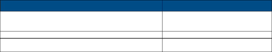
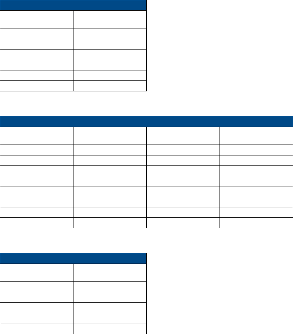
Additional Relevant Documents
The following documents are required if the corresponding units are included in your system (these can be downloaded from the
Corning partner portal).
Document Name
Part Number
5 band remote access unit datasheet CE0009001 Rev A00 (RAU5x)
CE0007202 Rev A00 (RAU5)
Corning optical network evolution (ONE™ ) system installation
709C011801 REV A01
Headend Control Module (HCM) and Web Management GUI
User Manual
709C014205 Rev. A00 and higher
Corning Optical Communications User Manual I CMA-482-AEN I Page 7
T
Ta
ab
bl
le
e
o
of
f
C
Co
on
nt
te
en
nt
ts
s
Warranties ............................................................................................................................................................. 2
Hardware Warranty ................................................................................................................................................ 2
Software Warranty ................................................................................................................................................. 2
Returns .................................................................................................................................................................. 3
Limitations of Liabilities .......................................................................................................................................... 4
Reporting Defects .................................................................................................................................................. 4
Warnings and Admonishments .............................................................................................................................. 4
Regulatory Compliance Information ....................................................................................................................... 4
RF Safety ............................................................................................................................................................... 5
Laser Safety ........................................................................................................................................................... 5
Company Certification ............................................................................................................................................ 6
Licensee Contact Information ................................................................................................................................. 6
Table of Contents ................................................................................................................................................... 7
1 Introduction ................................................................................................................................................. 11
1.1 Key Features and Capabilities .................................................................................................................... 11
1.2 General System Specifications and Requirements ...................................................................................... 12
1.2.1 Environmental and Regulatory Specifications .................................................................................. 12
1.2.1.1 Temperature and Humidity ....................................................................................................... 12
1.2.1.2 Safety and Regulatory Approvals .............................................................................................. 12
1.2.2 Power Specifications ....................................................................................................................... 13
1.2.2.1 Power Input and Consumption .................................................................................................. 13
1.2.2.2 Cable Gauge Requirements ..................................................................................................... 13
1.2.2.3 Power, Heat and Rack Specifications ....................................................................................... 14
1.2.2.4 Remote End Distance and Power Draw Matrix ......................................................................... 15
Corning Optical Communications User Manual I CMA-482-AEN I Page 8
1.3 Architecture ................................................................................................................................................. 17
1.4 Web Management Application .................................................................................................................... 18
2 Interfaces .................................................................................................................................................... 19
2.1 RAU5/RAU5x .............................................................................................................................................. 19
2.2 RxU............................................................................................................................................................. 21
2.3 RxU2325 ..................................................................................................................................................... 22
2.4 GEM ........................................................................................................................................................... 23
3 Installation Guidelines ................................................................................................................................. 25
3.1 Infrastructure Preparation ........................................................................................................................... 25
3.2 Installation Location Requirements ............................................................................................................. 25
3.3 Safety Guidelines ........................................................................................................................................ 25
3.4 Power Requirements .................................................................................................................................. 26
3.4.1 Power Safety Instructions ................................................................................................................ 26
3.4.2 Circuit Breakers ............................................................................................................................... 26
3.5 RF Coaxial Cable Guidelines ...................................................................................................................... 26
3.5.1 General Cable Installation Procedures ............................................................................................ 26
3.5.2 RF Rules ......................................................................................................................................... 26
3.5.3 Coax Cable Lengths and Losses ..................................................................................................... 27
3.6 Antenna Specifications and Guidelines ....................................................................................................... 28
3.6.1 Authorized Antennas and Required Specifications .......................................................................... 28
3.6.2 General Installation Guidelines ........................................................................................................ 28
3.7 Fiber Optic Requirements ........................................................................................................................... 28
3.7.1 Authorized Optic Cables .................................................................................................................. 28
3.7.2 Fiber Optic Rules ............................................................................................................................. 28
3.8 Power Safety Instructions ........................................................................................................................... 29
4 Installation................................................................................................................................................... 30
4.1 Package Contents ....................................................................................................................................... 31
4.2 Mounting ..................................................................................................................................................... 31
4.2.1 Standard Standoff Mount Installation ............................................................................................... 31
4.2.2 Top Bracket (Mid Mount Installation) ............................................................................................... 34
4.2.2.1 Package Contents .................................................................................................................... 35
4.2.2.2 Installing Bracket Assembly and Mounting RAU5x .................................................................... 35
4.2.2.3 Top Bracket Cap Assembly ...................................................................................................... 40
Package contents ....................................................................................................................................... 40
Corning Optical Communications User Manual I CMA-482-AEN I Page 9
To assemble the cap ................................................................................................................................... 41
To remove the cap ...................................................................................................................................... 41
4.2.3 Wall Mount ...................................................................................................................................... 43
4.2.3.1 Package Contents .................................................................................................................... 43
4.2.3.2 Installing Wall Mount Bracket and Mounting RAU5x ................................................................. 44
4.3 Connections ................................................................................................................................................ 48
4.3.1 Locate Required Connection Cables ............................................................................................... 48
4.3.2 Cable Connections .......................................................................................................................... 48
4.3.2.1 Grounding Connection .............................................................................................................. 48
4.3.2.2 RF Connections ........................................................................................................................ 49
4.3.2.3 Fiber Connections ..................................................................................................................... 51
4.3.3 Main Power Connections ................................................................................................................. 51
4.3.4 GEM Connections (for Configurations including GEMs)................................................................... 53
4.4 Verify Normal Operation .............................................................................................................................. 54
4.5 RAU5x/RxU Cavity Filter Installation ........................................................................................................... 56
4.5.1 Package Contents ........................................................................................................................... 57
4.5.2 (Concrete) Ceiling Mounting Option ................................................................................................. 57
4.5.3 Acoustic Ceiling Mount Installation .................................................................................................. 58
4.5.4 Wall Mount Installation..................................................................................................................... 58
4.5.5 Filter Connections ............................................................................................................................ 60
Corning Optical Communications User Manual I CMA-482-AEN I Page 10
5 Appendix A: Bracket Dimensions ................................................................................................................ 61
Top Bracket ......................................................................................................................................................... 62
Wall Mount Bracket .............................................................................................................................................. 63
6 Appendix B: Upgrades ................................................................................................................................ 65
6.1 Package Contents ....................................................................................................................................... 65
6.2 Installing the Plug-in Module in the RAU5x ................................................................................................. 65
7 Appendix C: Specifications ......................................................................................................................... 69
Supported Services .............................................................................................................................................. 69
RF Parameters ..................................................................................................................................................... 69
Optical ................................................................................................................................................................. 70
Environmental Specifications ............................................................................................................................... 70
Standards and Approvals ..................................................................................................................................... 70
Component Specifications ................................................................................................................................... 71
Remote Expansion Unit (RxU) .................................................................................................................... 72
2300 MHz/2500 MHz Remote Expansion Unit (RxU2325) .......................................................................... 72
Cavity Duplexer for LTE 700 MHz ............................................................................................................... 72
Cavity Duplexer for 800 MHz ...................................................................................................................... 73
Gigabit Ethernet Module (GEM) .................................................................................................................. 74
8 Appendix D: Ordering Information ............................................................................................................... 75
Accessories ......................................................................................................................................................... 76
Corning Optical Communications User Manual I CMA-482-AEN I Page 11
1 Introduction
The five band remote access unit (RAU5/RAU5x) is a fiber fed, multi-service indoor coverage remote solution for the Corning
Optical Network Evolution (ONE™) cellular solutions. It enables multiple wireless technologies and operator services to be
distributed over a single broadband infrastructure. The remote access unit supports up to five SISO services (model dependent)
in various combinations in addition to two MIMO services via an expansion module. The RF services are routed from the
headend according to user defined service groups over single-mode fiber and converted for distribution by the specified
remotes via an external broadband antenna
Note: RAU5/RAU5x can be ordered with a preassembled Corning external antenna or can be connected to external omni
directional or directional antennas complying with the requirements specified in Section
3.6.1.
The remote unit can host two additional modules:
• Remote expansion unit (RXU) – provides MIMO support for LTE700, and AWS
• Gigabit Ethernet module (GEM) – provides Gigabit Ethernet support, enabling offload, expansion and effective use of Wi-Fi
resources. Ethernet services from the corporate LAN (received via Ethernet Switch) are converted to optic signals by the
CEU (Centralized Ethernet Unit) and routed over optic fibers towards the GEM units. The optical traffic is then converted to
1GbE by the GEM and distributed to two third party equipment such as access points, Ethernet switch, etc.
The remote access unit can be deployed alongside other Corning Optical Network Evolution (ONE™) Solutions remotes (e.g.,
mid-power remote unit – MRU), sharing a common headend and element management system. Management and configuration
options are provided for each remote access unit service via a Web session to the headend control module (HCM).
1.1 Key Features and Capabilities
• Multi-frequency/ multi-service platform: supports five services: ESMR 800/CELL 850, LTE 700, AWS+AWS3* 1700, and PCS 1900
• Multi-operator optimized platform - services from a number of operators can be distributed by the same unit
• Operator grade performance - advanced signal handling, RF filtering and management ensures operator grade performance
• Optic fiber savings - all services are routed over a single optic fiber pair
• Seamless MIMO upgradeability - modular design supports expansion module (RXU) for additional LTE and AWS MIMO
service
• Ethernet support - supports “plug in” GEM module providing support for connected IP devices (Wi-Fi APs, IP Phones, etc.)
with Ethernet pass through and PoE
• Simple installation and maintenance - provided with easy-to-install mounting bracket; all interfaces located on front panel
• Array of mounting options – various accessory kits available to accommodate different mounting options: wall/ceiling mount,
back-to-back wall mount, acoustic ceiling installations
• Management and control - alarm forward to NOC or standard EMS via SNMP, software controlled output power and optical link
auto gain control
*RAU5 supports AWS; RAU5x supports AWS1/3
Corning Optical Communications User Manual I CMA-482-AEN I Page 12
1.2 General System Specifications and Requirements
1.2.1 Environmental and Regulatory Specifications
1.2.1.1 Temperature and Humidity
Operating
Storage
Temperature 0°C to +50°C (32°F to 122°F) -20° C to 85° C (-4°F to 185°F)
Humidity 95% (non-condensing) 95% (non-condensing)
Table 1-1. Temperature and Humidity Specifications
1.2.1.2 Safety and Regulatory Approvals
Regulation/Standard
Category
Approval
Laser Safety FDA/CE 21 CFR 1040.10 and 1040.11 except for deviations pursuant to laser notice no.
50 and IEC 60825-1
EMC CE EN 301 489, EN55022, EN 61000
FCC 47 CFR Part 15, 22, 24, 27
Safety
UL 60950
IEC 60825-1:2007
IEC 60825-2:2010
CAN/CSA-C22.2 No.60950-1-03
Fire Safety UL 2043
Table 1-2. Safety and Regulatory Approvals
Corning Optical Communications User Manual I CMA-482-AEN I Page 13
1.2.2 Power Specifications
Note: This section references RAU5x, however power specifications are the same for both RAU5 and RAU5x.
1.2.2.1 Power Input and Consumption
RAU5x + Add-On Modules
Max. Power Consumption
Power Input Range
RAU5x (alone)
44.5 V; 50 W 37 – 57 V DC
RAU5x + RXU
44.5 V; 76 W
RAU5x + GEM
44.5 V; 52 W
RAU5x + RXU + GEM
44.5 V; 78 W
Table 1-3. RAU5 Power and Current Consumption for Main Power Input
Unit
Device
Input Range
Power Consumption
RAU5x For two PoE ports of 802.3af 43- 57 V DC 46 V; 31.5 W
For two PoE ports of 802.3at 52- 57 V DC 52.5 V; 62 W
Table 1-4. RAU5x Power and Current Consumption for Secondary Input
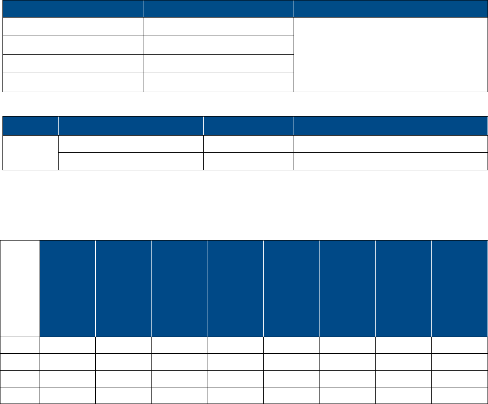
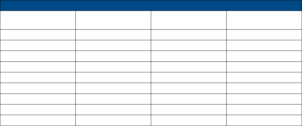
1.2.2.2 Cable Gauge Requirements
Table 1-5 provides the information required to calculate the required power supply for the remote units.
RAU5x
SISO
(ft)
RAU5x
SISO +
GEM
(ft)
RAU5x
SISO +
GEM
Supporting
PoE
RAU5x
SISO +
GEM
Supporting
PoE+
(ft)
RAU5x
MIMO
(ft)
RAU5x
MIMO
+
GEM
(no PoE)
(ft)
RAU5x
MIMO
+
GEM
Supporting
PoE
(ft)
RAU5x
MIMO
+
GEM
Supporting
PoE+
(ft)
22AWG
540 490 410 100 310 290 290 100
20AWG
870 780 650 160 500 460 460 160
16AWG
2200 1900 1600 400 1200 1100 1100 400
14AWG
3500 3100 2650 650 2010 1800 1800 650
Table 1-5. Required Cable Gauge

Corning Optical Communications User Manual I CMA-482-AEN I Page 14
1.2.2.3 Power, Heat and Rack Specifications
Table 1-6 provides the power, heat and rack specifications for the remote end ceiling equipment.
Unit
Description
Min-Max
Voltage
(VDC)
Max Power
Draw (Watts)
Heat
(BTU/
hr)
Dimensions (in)
RAU5x 5-Band remote access unit 37 - 57 50 171 Without mounting
bracket: 3.2 x 12.9 x
9.8 in (82.1 x 337.3
x 249.4 mm)
With mounting
bracket: 5.25 x 13.1
x 13.1 in (133.35 x
332.74 x 332.74
mm)
RXU Remote Expansion Unit 37 - 57 25 85 1.1 x 12.8 x 9.8
RAU5x + RXU Remote Access Unit + Remote
Expansion Unit
37 - 57 78 267 13.1 x 13.1 x 4
GEM Gigabit Ethernet Module 37 - 57 4 14 1.3 x 3.8 x 5.9
GEM Supporting
PoE
For two PoE ports of 802.3af: 43V; 30W
For two PoE ports of 802.3at: 52V; 62W
Table 1-6. Power, Heat and Rack Specifications for Ceiling Equipment (Remote End)
Corning Optical Communications User Manual I CMA-482-AEN I Page 15
1.2.2.4 Remote End Distance and Power Draw Matrix
Table 1-7, Table 1-8, Table 1-9 and Table 1-10 provide the distance and power draw specifications for the remote end units.
RAU5x SISO
Composite 16 AWG
Tether Distance (ft.)
Draw (Watts)
10 - 50 36
60 - 270 37
280 - 480 38
490 - 690 39
700 - 850 40
860 - 900 41
*Min/Max VDC = 37/57 @ 1.49 Amps, 85% efficiency
Table 1-7. Remote End Distance and Power Draw for (Standalone) RAU5x SISO
RAU5x+ RXU (MIMO)
Composite 16 AWG
Tether Distance (ft.)
Draw (Watts) Composite 16 AWG
Tether Distance (ft.)
Draw (Watts)
10 – 100 62 570 – 610 70
110 – 170 63 620 – 660 71
180 – 240 64 670 – 710 72
250 – 320 65 730 – 750 73
330 – 380 66 760 – 790 74
390 - 440 67 800 – 830 75
450 - 510 68 840 – 860 76
520 - 560 69 870 - 900 77
*Min/Max VDC = 37/57@ 1.49 Amps, 85% efficiency
Table 1-8. Remote End Distance and Power Draw for RAU5x + RXU (MIMO)
GEM Supporting PoE 802.3af
Composite 16 AWG
Tether Distance (ft.)
Draw (Watts)
10 - 40 31
50 - 340 32
350 - 660 33
670 - 890 34
900 35
*Min/Max VDC = 43/57 @ 1.49 Amps, 85% efficiency
Table 1-9. Remote End Distance and Power Draw for GEM w/PoE.3af
Corning Optical Communications User Manual I CMA-482-AEN I Page 16
GEM Supporting PoE 802.3at
Composite 16 AWG
Tether Distance (ft.)
Draw (Watts) Composite 16 AWG
Tether Distance (ft.)
Draw (Watts)
10 - 80 64 590 - 620 73
90 - 170 65 630 - 670 74
180 - 230 66 680 - 710 75
240 - 300 67 720 – 750 76
310 - 370 68 760 – 790 77
380 - 420 69 800 - 820 78
430 - 470 70 830 - 850 79
480 - 530 71 860 - 890 80
540 - 580 72 900 81
*Min/Max VDC = 52/57 @ 1.49 Amps, 85% efficiency
Table 1-10. Remote End Distance and Power Draw for GEM w/PoE.3at
Corning Optical Communications User Manual I CMA-482-AEN I Page 17
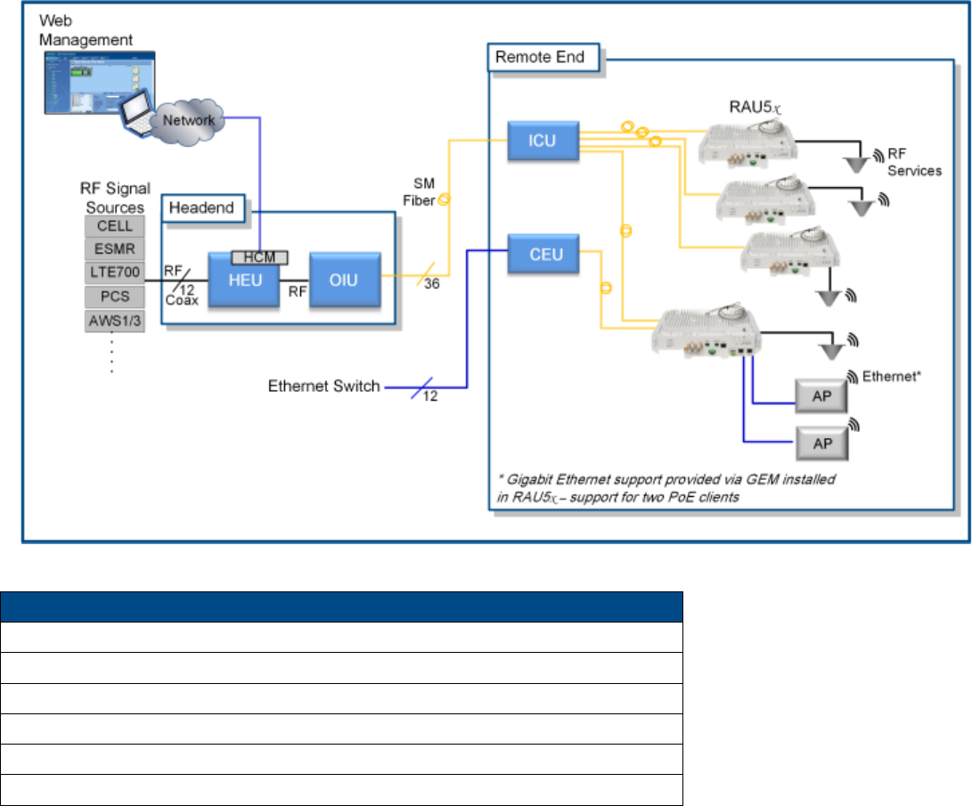
1.3 Architecture
The remote access units distribute the wireless and Ethernet services received over the fiber-optic infrastructure from the
Corning optical network evolution (ONE™) solution headend.
The remote access units are service-specific modules supporting five SISO services that perform optical to RF conversion of
signals received from the optical interface unit (OIU) at the headend. Signals are automatically filtered, amplified and distributed
via external antennas. Uplink signals are then converted to optical signals before being transmitted back to the OIU.
Figure 1-1. Corning ONE Basic Architecture
Acronyms
HEU = Headend unit
RAU5x = Five Band remote access unit
ICU = Interconnect unit
IHU = Integrated headend unit
CEU = Centralized Ethernet unit
OIU = Optical interface unit
Table 1-11. Acronyms in System Architecture
Corning Optical Communications User Manual I CMA-482-AEN I Page 18
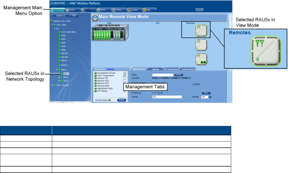
1.4 Web Management Application
The Corning Optical Network Evolution (ONE™) Solution headend control module (HCM) enables centralized, system-level
element management and
provides c
omprehensive end-to-end, single source setup and management of the active RF system
components after their physical installation
.
Management capabilities are provided for both the RAU5x and installed RF
expansion module.
Note: Refer to the Corning ONE
™ HCM and management GUI user manual for a complete description of the web management
application.
Figure 1-2. RAU5/RAU5x Management Window
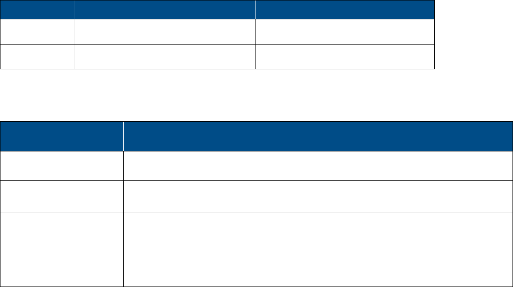
The RAU5x Management tabs include the following:
Tab
Description
Device Alarms
Module specific alarms used for fault sourcing
Module Info
Provides device version and identification definition
Alarms
Service level alarms
RF Parameters Includes configurable RF parameters such as output power and service on/off
option.
Comments
Used to enter any information relevant to the selected device
Table 1-12. RAU5x Management Tabs
Corning Optical Communications User Manual I CMA-482-AEN I Page 19
2 Interfaces
2.1 RAU5/RAU5x
Note the following:
• This section references RAU5x, however interfaces are the same for both RAU5 and RAU5x.
• The RAU5x can host two additional modules: RXU for MIMO support (e.g., LTE700 and AWS) and GEM for digital coverage.
See relevant sections for details on these modules.
• Specific RAU5/RAU5x models are available with provided external antenna enclosure.
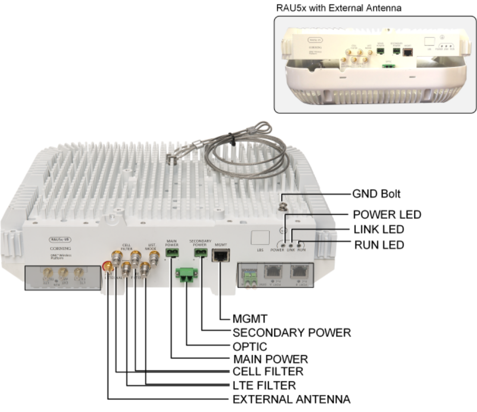
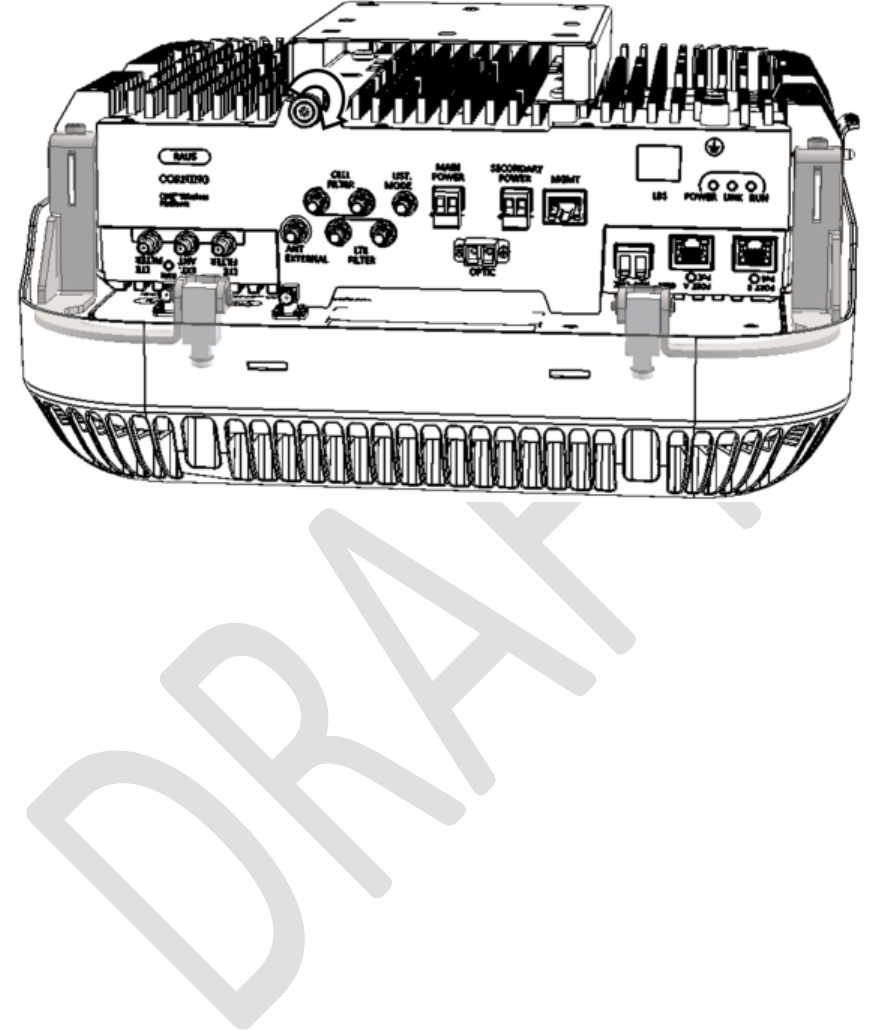
Figure 2-1. RAU5x Interfaces
Corning Optical Communications User Manual I CMA-482-AEN I Page 20
Interface
Description
MGMT RJ-45 local management connection
MAIN POWER Main DC input; Input range: 37 – 57 VDC; DC power fed from composite
cable; Refer to section 1.2.2.1 for power consumption
SECONDARY POWER Secondary DC input required for use in addition to “‘MAIN POWER” with PoE
clients (installations including GEM module); Refer to section 1.2.2.1 for
power input per PoE port and consumption
LIST. MODE N/A
EXTERNAL ANTENNA QMA connector for external broadband antenna connection
CELL/LTE FILTER Two QMA RF connectors (In/Out) per external cavity filter type (i.e. LTE and
CELL)
OPTIC LC APC SM connectors for UL and DL fiber optic connections
GROUNDING BOLT 8-32 x 3/8 grounding screw used for connecting RAU5x to earth ground
Table 2-1. Connection Interface Descriptions
LED
Description
POWER Steady green - power input detected by remote unit
Off - no power supplied to remote unit
LINK Steady green – Optical link power to/from the remote unit is normal
Blinking green – Optical power from remote is lower than required
Off – no optical link is detected
RUN Blinking green blinking – software initializing
Steady green – boot up sequence complete and module software up and
running
Off – no power supplied to unit
Table 2-2. LED Descriptions
Corning Optical Communications User Manual I CMA-482-AEN I Page 21
2.2 RxU
The RXU is an add-on module to the RAU5x which provides support for MIMO services (i.e. 700 MHz LTE, AWS).
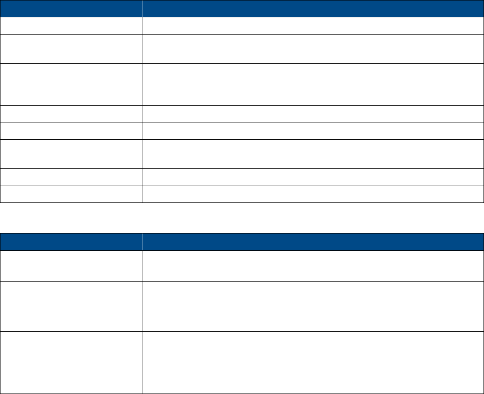
Figure 2-2. RxU Interfaces
Module
Description
External Antenna RF Connection to external antenna. Antenna must have a return loss of 12 dB.
(Both the RxU and the RAU5/RAU5x external antenna connections are used
since this implements a MIMO configuration)
External RF Filters QMA RF ports for external cavity filter use (if required by site planner). For
CELL and LTE filters.
RUN LED Indicates software is up and running.
Table 2-3. RxU Front Panel Interface Connections
Corning Optical Communications User Manual I CMA-482-AEN I Page 22
2.3 RxU2325
The RxU2325 is an add-on module which plugs into the RAU5x and enables support for two additional bands: 2.3 GHz WCS
and 2.5 GHz LTE (TDD).
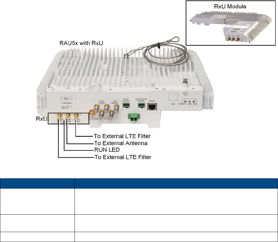
Figure 2-3. RxU2325 Interfaces
Module Description
To RAU QMA RF connector; Connects to RAU5x
ANT. QMA RF connector; Connects to external antenna
UL/DL External QMA RF ports for external cavity filter use (if required by site planner). For
CELL and LTE filters.
Table 2-4. RxU2325 Interface Connections
Corning Optical Communications User Manual I CMA-482-AEN I Page 23
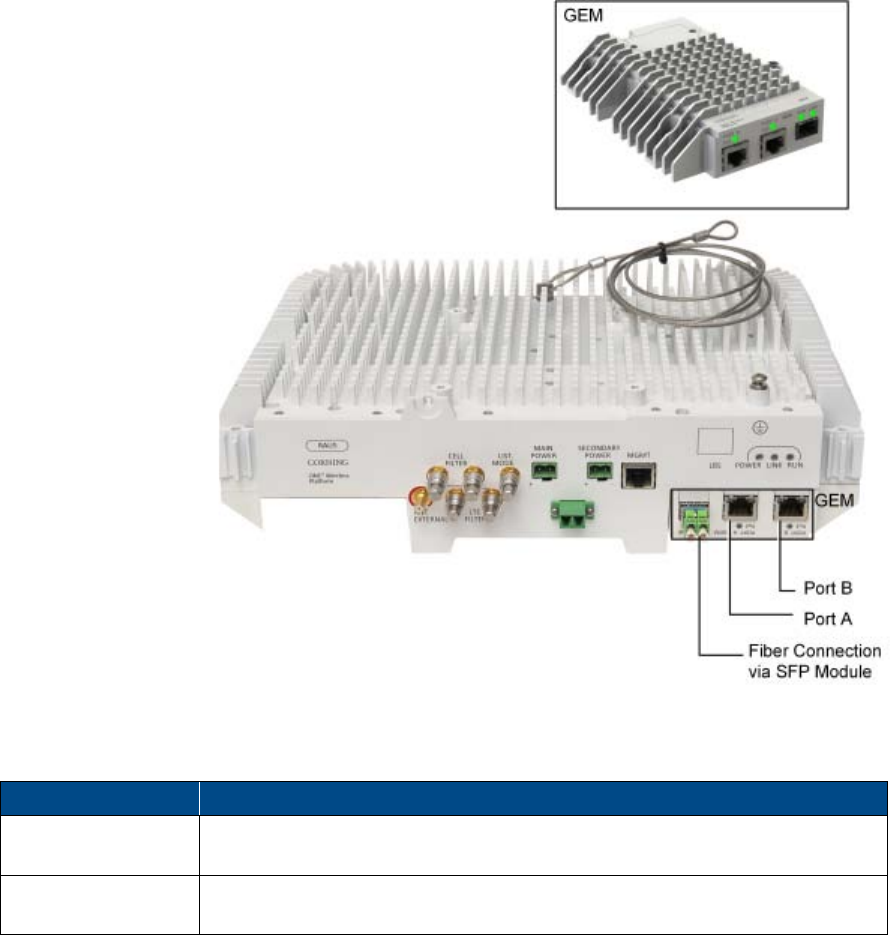
2.4 GEM
The GEM is an add-on module that provides Gigabit Ethernet support - the received optical signal is converted to two Ethernet
digital connections, which can then routed along with PoE to third party equipment.
Figure 2-4. GEM Interfaces
Table 2-5 and Table 2-6 provide descriptions of the ports and LED indicators.
Port
Description
PORT A/PORT B Two 10/100/1000Base-T copper interface with 802.3at compliant Power over
Ethernet (PoE+) PSE ports capability for connections to remote access points
FC APC One 1000BASE-X T Copper port to LC UPC fiber connectors (using SFP
–small-form pluggable module) towards CEM module
Table 2-5. GEM Port Interfaces
Corning Optical Communications User Manual I CMA-482-AEN I Page 24
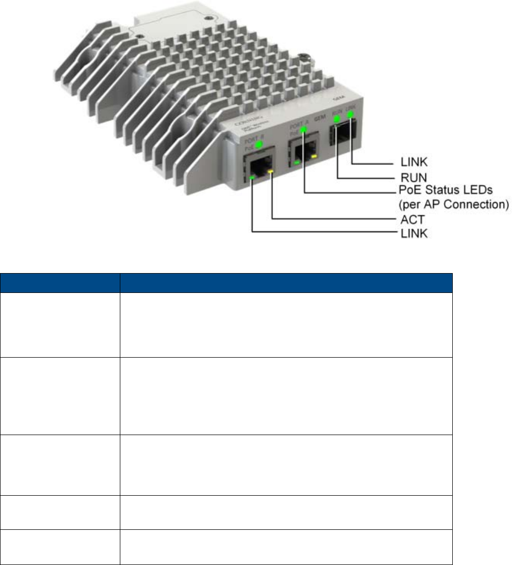
Figure 2-5. GEM LED Description
LED Description
PoE (PORT A/PORT B) Steady Green: Indicates power supplied to connected AP; PoE
enabled
Steady Yellow: Indicates PoE fault
Off: Off
SFP LINK Steady Green: Optical link to/from the connected remote
functions within the specifications in both
directions.
Blinking Green: Indicates activity over the optical link
Off: No link
RUN Steady Green with
short blink every ~10
sec. (heartbeat):
On/Normal
Steady Yellow: GEM module fault
LINK Steady Green: Link
Off: No link
ACTIVITY Blinking Yellow: Activity
Off: No activity
Table 2-6. GEM LED Indicator Descriptions
Corning Optical Communications User Manual I CMA-482-AEN I Page 25
3 Installation Guidelines
The following installation assumes that site survey and installation planning (including power requirements) have been
completed. This includes planning the distribution of antennas to provide the required coverage, as well as planning the layout
of the devices and cables in the telecom closet or shaft.
3.1 Infrastructure Preparation
The following installation rules are based on the assumption that the site survey and installation planning (including power
requirements) have been completed as well as the floor plan determining the distribution of the remote access units on each
floor to provide the required coverage
3.2 Installation Location Requirements
• Mounting surface shall be capable of supporting the weight of the equipment.
• In order to avoid electromagnetic interference, a proper mounting location must be selected to minimize interference from
electromagnetic sources such as large electrical equipment.
• Working space available for installation and maintenance for each mounting arrangement.
• Ensure unrestricted airflow.
• Ensure grounding connector is within reach of the ground wire.
• Ensure a power source is within reach of the power cord and the power source has sufficient capacity.
• Where appropriate, ensure unused RF connectors are terminated.
• Do not locate the equipment near large transformers or motors that may cause electromagnetic interference.
• Reduce signal loss in feeder cable by minimizing the length and number of RF connections.
• Ensure the equipment will be operated within the stated environment (refer to Appendix C: Specifications or unit datasheet).
• Where appropriate, confirm available of suitably terminated grade of RF and optical fiber.
• Observe handling of all cables to prevent damage.
3.3 Safety Guidelines
Before installing the equipment review the following safety information:
• Follow all local safety regulations when installing the equipment.
• Only qualified personnel are authorized to install and maintain the equipment.
• Ground specified equipment with the provided grounding bolt
• Do not use the grounding bolt to connect external devices.
• Follow electro-static discharge (ESD) precautions.
• Use low loss cables to connect the antennas
Corning Optical Communications User Manual I CMA-482-AEN I Page 26
3.4 Power Requirements
This section summarizes the RAU5x power requirements.
Note: This section references RAU5x, however power requirements are the same for both RAU5 and RAU5x.
3.4.1 Power Safety Instructions
SAFETY WARNINGS! When installing or selecting the power supplies:
• Only use the power cables and any other relevant accessories provided with the unit to connect the power supply to the
system components.
• Be sure to disconnect all power sources before servicing.
• Calculate the required power according to the requirements of the specific installation and then determine the configuration
of the power supplies. The required DC cables will then be determined by the selected power supply configuration.
• Use only UL approved power supplies
• Install external over-current protective devices for the system according to the requirements described in section 1.2.2 -
Power .
3.4.2 Circuit Breakers
Calculate the required fuse protection while referring to section 1.2.2 - Power . Also, take into account when installing fuse
protections for the system that there may be other Corning system elements that require external fuse protection.
3.5 RF Coaxial Cable Guidelines
3.5.1 General Cable Installation Procedures
Note: The installer should be familiar with the ANSI/TIA/EIS-568 Cabling Standard guidelines.
Observe the general cable installation procedures that meet with the building codes in your area. The building code requires
that all cabling be installed above ceiling level (where applicable). The length of cable from the risers to each antenna must be
concealed above the ceiling.
The cable must be properly supported and maintained straight using velcro cable ties, cable trays and clamps or hangers every
10 feet (where practical above ceiling level). Where this is not practical, the following should be observed:
• The minimum bending radius of the supplied ½” coax cable should be 7”.
• Cable that is kinked or has a bending radius smaller than 7” must be replaced.
• Cable runs that span less than two floors should be secured to suitably located mechanical structures.
• The cables should be supported only from the building structure.
• All cables shall be weather-resistant type.
• Cable length - determined by the system installation plan. When calculating the cable length, take into account excess cable
slack so as not to limit the insertion paths.
3.5.2 RF Rules
• Use coax RG-223, 50 ohm, male-to-male N-type to QMA for RF connections from the RIMs to the BTS/RBS and to the
RAU5xs.
• When using the Corning system in an environment in which other indoor coverage systems are installed, it is recommended
(where possible) that the antennas are placed at least two meters apart
• When bending coax cables, verify that the bending radius does not exceed the coax specifications.
• Use a VSWR meter (i.e. Site Master or equivalent) for checking coax cables, including the antennas. (<2). The VSWR must
be measured prior to terminating the RAU5xs at the remote locations

Corning Optical Communications User Manual I CMA-482-AEN I Page 27
3.5.3 Coax Cable Lengths and Losses
Use coax ½”, 50ohm, male-to-male QMA type, for connecting to RAU5x and external antenna ports.
Note: The required distance between the antennas (installed in the ceiling) depends on the infrastructure and calculated
path-loss. For example, if there is free space-loss between the antennas, a minimum distance of 100 ft is required; if there are
partitions (loss) between the antennas, a distance of less than 100 ft between them is allowed.
Coax Length
Coax Loss
(900 MHz)
Connector
Loss
Total Loss
30 0.7 1.5 2.2
40 0.9 1.5 2.4
50 1.1 1.5 2.6
60 1.3 1.5 2.8
70 1.5 1.5 3
80 1.7 1.5 3.2
90 1.9 1.5 3.4
100 2.1 1.5 3.6
110 2.3 1.5 3.8
120 2.5 1.5 4
130 2.7 1.5 4.2
140 2.9 1.5 4.4
150 3.1 1.5 4.6
160 3.3 1.5 4.8
170 3.5 1.5 5
180 3.7 1.5 5.2
190 3.9 1.5 5.4
200 4.1 1.5 5.6
Table 3-1. Coax Cable Lengths and Losses
Corning Optical Communications User Manual I CMA-482-AEN I Page 28
3.6 Antenna Specifications and Guidelines
Determine the antenna installation configuration, according to the transmission and coverage requirements and the installation
site conditions.
3.6.1 Authorized Antennas and Required Specifications
• RAU5x requires external broadband antenna - can be ordered with preassembled external antenna enclosure.
• External antennas - No limitation on any vendor of available external antennas with respect to the following requirements:
• Omni Directional or Directional
• Supported frequency range: wideband antennas supporting a range of 700 MHz to 2600 MHz
• Gain: up to 12.5 dBi
• Impedance: 50 Ohm
• Return Loss: +12 dB
• Number of antennas that can be connected (with cables/splitters) – it is not recommended to connect more than one
antenna per connector since 1:1 connectivity is reduced with each split.
• Types of couplers/splitters – depends on number of splits (not recommended)
3.6.2 General Installation Guidelines
• The RAU5x should be installed at a convenient location, free of metallic obstruction (can also be installed in plenum spaces).
• Install the RAU5x at the designated height and tune it roughly toward the service coverage area.
• Installation of this antenna must provide a minimum separation distance of 20 cm from any personnel within the area.
• Cable and jumper loss is at least 2 dB.
3.7 Fiber Optic Requirements
3.7.1 Authorized Optic Cables
The following specified optic cables are authorized for use with the RAU5/RAU5x:
• Composite Plenum Tether Assemblies
• Fiber: LC APC, 2 – 24 fibers
• Cu: 16AWG, 14AWG, 12AWG; 2 – 12 Conductors
• Armored, non-armored
3.7.2 Fiber Optic Rules
• Use only or LC APC connectors
• UniCam connectors can be used for field termination
• Use only fusion splice for connecting two fibers
• Use minimum splicing/connectors to achieve minimum losses on the fibers (< 0.5 dB)
• Use precaution while installing, bending, or connecting fiber optic cables:
• Fiber optic cable is sensitive to excessive pulling, bending and crushing forces. Consult the cable specification sheet for
the cable you are installing.
• Do not bend cable more sharply than the minimum recommended bend radius.
• Do not apply more pulling force to the cable than specified.
• Do not crush the cable or allow it to kink. Doing so may cause damage that can alter the transmission characteristics of
the cable. The cable may have to be replaced.
• Use an optical power meter and light source for checking the fiber optic cables
• Make sure the environment is clean while connecting/splicing fiber optic cables

Corning Optical Communications User Manual I CMA-482-AEN I Page 29
• All fiber optic connectors should be cleaned prior to connecting to the system
• Fiber connector protective caps should be installed on all non-terminated fibers and removed just before they are
terminated.
• LC APC connectors – ensure that you hear a “click”, indicating a secure connection
• Never look directly into the end of a fiber that may be carrying laser light. Laser light can be invisible and can damage your
eyes.
3.8 Power Safety Instructions
SAFETY WARNINGS
• When installing or selecting the power supplies:
• Be sure to disconnect all power sources before servicing.
• Calculate the required power according to the requirements of the specific installation and then determine the configuration
of the power supplies. The required DC cables will then be determined by the selected PS configuration.
• Use only UL approved power supplies
• AC and DC power supply cables – only use the power cords supplied with the units
• Install external over-current protective devices for the system according to the requirements described in section 1.2.2.
Types of Power Supplies
Corning supplies various enclosed power supplies (i.e. ICU and PSU6) that can be installed in a rack or mounted on a wall,
depending on your configuration.
Corning Optical Communications User Manual I CMA-482-AEN I Page 30
4 Installation
This chapter describes the installation of the RAU5/RAU5x. For specific guidelines on infrastructure planning, design and
installation, please consult with a Corning product line manager or Corning approved Installer.
The remote end site (RF coverage) installation consists of installing the ICU and RAU5/RAU5x modules.
General Information
1. The remote access unit must always be mounted parallel to the ceiling (horizontal) or wall (vertical) with a 1-in clearance
from the surface on the back and front to allow for proper cooling airflow and for heat dissipation.
2. Required ambient temperature:
• Wall-mount installations (vertical): 45◦C [113◦F]
• Ceiling-mount installations (horizontal): 50◦C [122◦F]
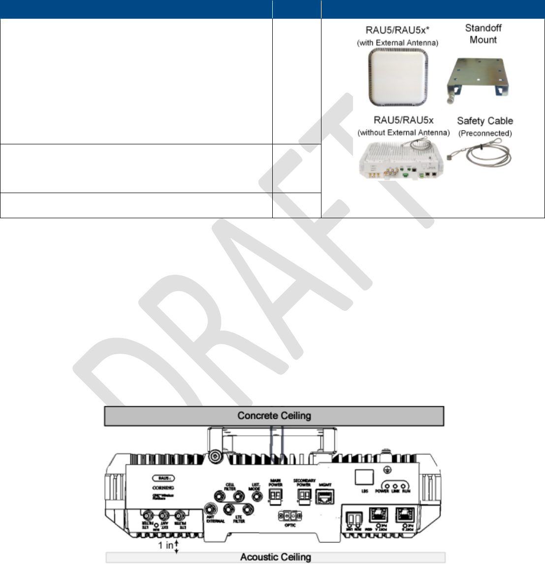
3. The RAU5 unit is provided with a standoff mount used for mounting on the wall or concrete ceilings (including above acoustic
ceiling mounts). Additional mounting accessory kits are available (ordered separately):
• BR-RAU5US-TOP: “Lift Bracket” for floating ceilings tile, mid-mount installation
• BR-RAU5US-Wall: Wall-mount bracket; Supports up to two remote access units back-to-back
4. Weight:
• RAU5x alone: 10 lbs (4.54 kg)
• RAU5x + RXU + GEM: 14.39 lbs (6.5 kg)
• External antenna: 3.7 lbs (1.7 kg)
5. A broadband antenna is required for RAU5x models ordered without a preassembled connected antenna (see Table 4-1 for
RAU5x models).
6. External cavity filters are required for installations in which RAU5x/RXU modules supporting the corresponding CELL and
LTE bands are deployed alongside units supporting the public safety service. Installation instructions are provided with each
separately ordered filter (AK-CVT700; AK-CVT800).
Corning Optical Communications User Manual I CMA-482-AEN I Page 31
4.1 Package Contents
Note: Check your package contents to verify that the items in the packing list are included. If any of the listed items are missing,
contact your Corning representative.
Item
Quantity
5 Band Remote Access Unit (RAU5/RAU5x):
• RAU5XUS • RAU5US-ME
• RAU5XUS-A* • RAU5US-M
• RAU5XUS-E • RAU5US-A*
• RAU5XUS-AE* • RAU5US-AE*
• RAU5US • RAU5US-AM*
• RAU5US-E • RAU5US-AME*
*RAU5/RAU5x model with preassembled external broadband antenna
1
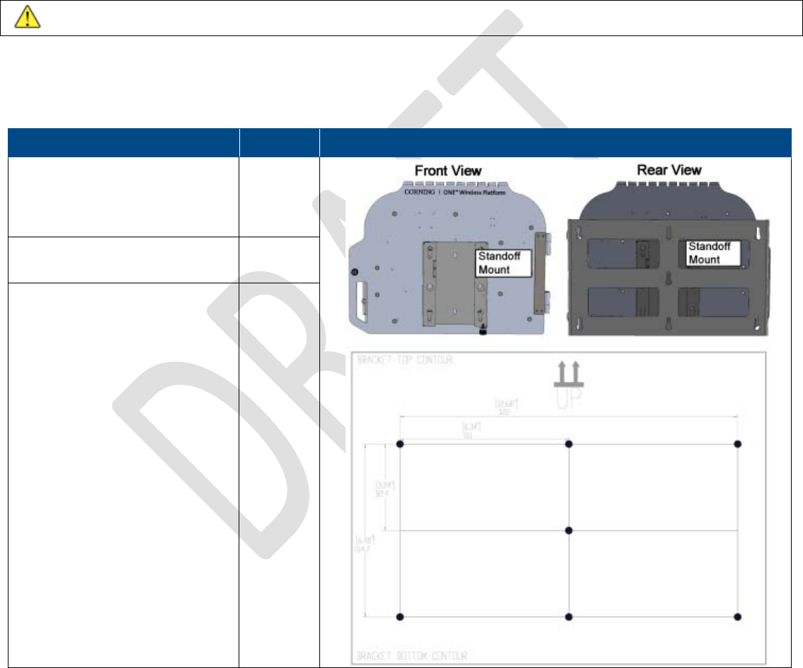
Standoff mount (preassembled on RAU5/RAU5x underside)
Note: Standoff mount includes holes in various sizes and
locations for flexible installation options.
Screws for mounting
on surface are not provided.
1
Safety Cable – preconnected to the RAU5/RAU5x
1
Table 4-1 Package Contents
4.2 Mounting
Note: This section references RAU5x, however mounting procedures are the same for RAU5 and RAU5x.
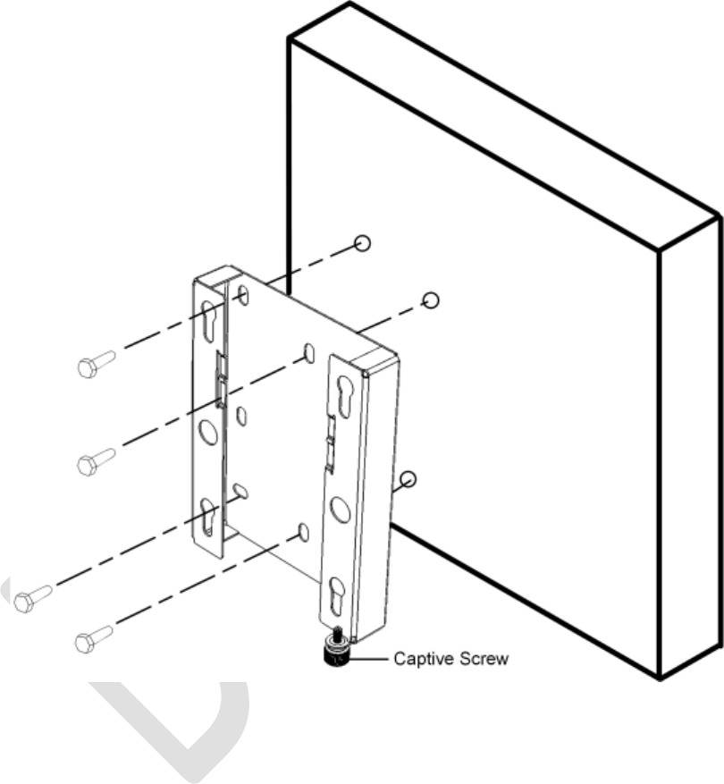
4.2.1 Standard Standoff Mount Installation
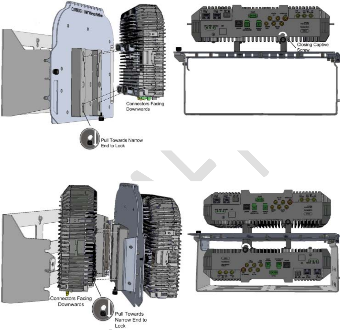
Note the following:
• The installation procedure for the standoff mount provided with the RAU5x refers to wall and concrete ceiling installations.
• When mounting the bracket on a wall the captive screw (indicated in Figure 4-1) should always be positioned in the same
direction as the RAU5x connectors.
• In wallmount installations the connectors should face downwards.
• If installing above acoustic ceiling, allow for at least one inch above the acoustic ceiling for air flow cooling.
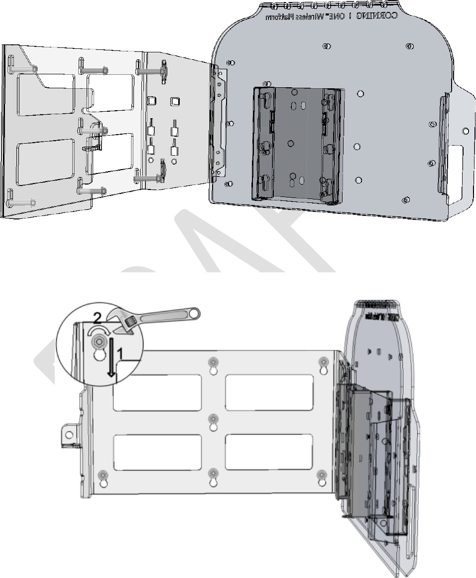
Figure 4-1.Example of (Concrete) Ceiling Installation of Mounting Bracket (RAU5x without External Antenna)
Corning Optical Communications User Manual I CMA-482-AEN I Page 32
To mount the standoff mount
1. Remove the mount from the RAU5x underside and use to mark and drill appropriate holes for mounting the bracket on the
wall or concrete ceiling. Refer to Appendix C for bracket dimensions.
2. Any of the applicable screw holes can be used.
3. Drill the appropriate screws (not provided) through the bracket installation holes and secure to surface.
Note: The RAU5x connectors should face the standoff mount captive screw.
Figure 4-2. Example of Standoff Mount Installation on Wall
Corning Optical Communications User Manual I CMA-482-AEN I Page 33
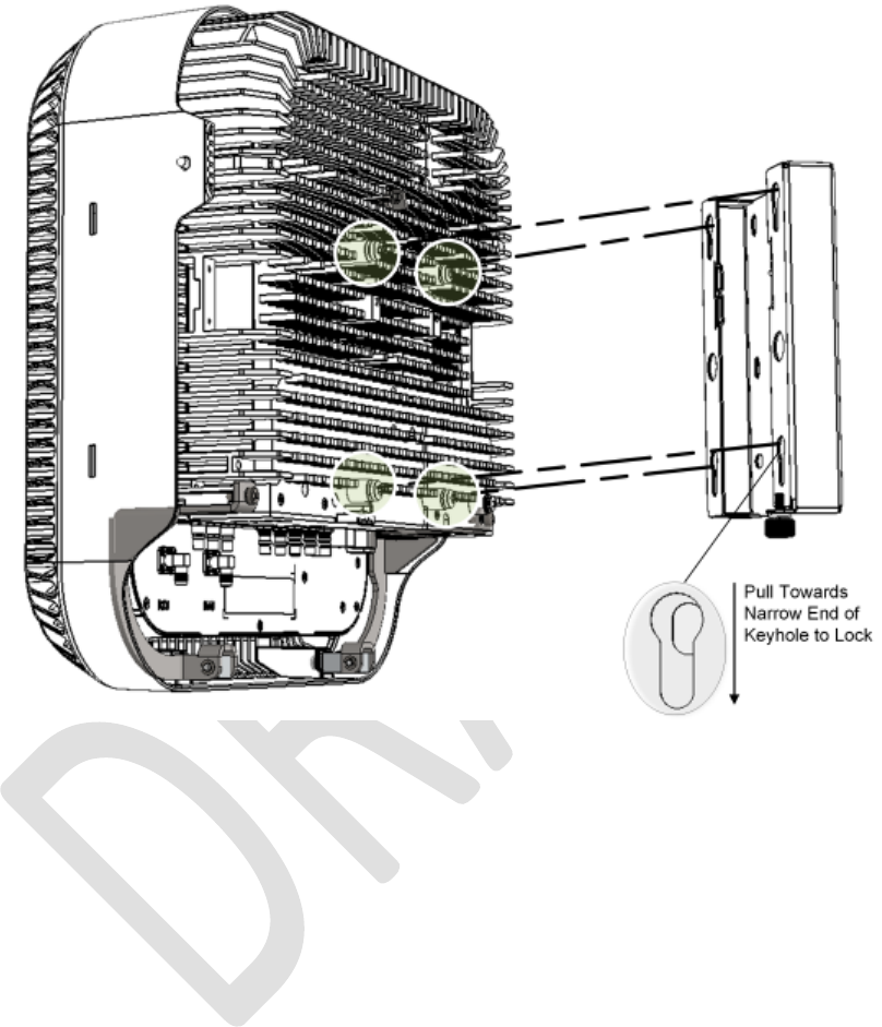
To mount the RAU5x onto the standoff mount
1. Insert the four RAU5x pins into the wide ends of the standoff mount key-holes.
2. Make sure that the captive screw fits into the designated half-slot on the RAU5x.
3. Lock RAU5x pins into the narrow ends of the standoff mount keyholes.
Figure 4-3. Mounting RAU5x onto Bracket
Corning Optical Communications User Manual I CMA-482-AEN I Page 34
4. Close captive screw to secure RAU5x and standoff mount assembly. See Figure 4-4.
Figure 4-4. Closing Bracket Captive Screw
5. Using the supplied security cable, attach the RAU5x to a permanent structure within the ceiling (e.g. acoustic ceiling grid or
concrete ceiling above).
4.2.2 Top Bracket (Mid Mount Installation)
This section provides instructions on how to assemble the RAU5 onto the mid-mount bracket and install the assembly in an
acoustic ceiling.
ATTENTION!
• Both the RAU5x and bracket plate must be secured to a permanent structure using safety cables. The RAU5x unit is
provided with an attached safety cable;
• A three inch clearance is required above and below the RAU5x unit from any object such as walls or ceiling to allow airflow
cooling.
Note the following:
• The “Top Bracket” plate is designed to replace a standard acoustic ceiling tile.
• It is recommended to perform the RAU5x connections after the unit is secured to the “Lift Bracket” (refer to section 4.3 for
cable connections).
• For RAU5x units without external antennas, a cap can be ordered separately and assembled onto the RAU5x and top
bracket assembly. See Section 0.
Corning Optical Communications User Manual I CMA-482-AEN I Page 35
4.2.2.1 Package Contents
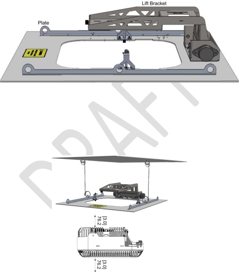
The RAU5x “Top Bracket” kit (BR-RAU5-TOP) consists of a plate and Lift Bracket assembly. Refer to Appendix A:
Bracket Dimensions for “Top Bracket” dimensions.
Figure 4-5. “Top Bracket” Assembly Lift Bracket and Plate
4.2.2.2 Installing Bracket Assembly and Mounting RAU5x
Note: The figures in this section, illustrate the top bracket installation with an RAU5 which includes the Corning external
antenna.
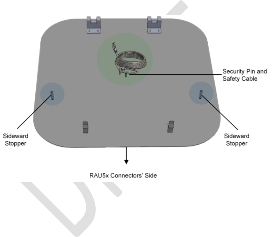
To install bracket and mount RAU5x
1. Install the plate in the ceiling and using the two safety cables, pre-connected to the middle safety rings of the plate, secure to
secure to a permanent structure.
Figure 4-6. Installing “Top Bracket” Plate
Corning Optical Communications User Manual I CMA-482-AEN I Page 36
ATTENTION!
• Plate must be secured before installing the RAU5x unit!
• If the bracket is not secured via the two middle safety rings, it must be secured with safety cables via the four remaining
safety rings.
• A 3 in clearance is required from the surface above and below the RAU5x unit to allow for proper cooling airflow and for heat
dissipation.
• The installer is responsible for accommodating the installation to the surface type.
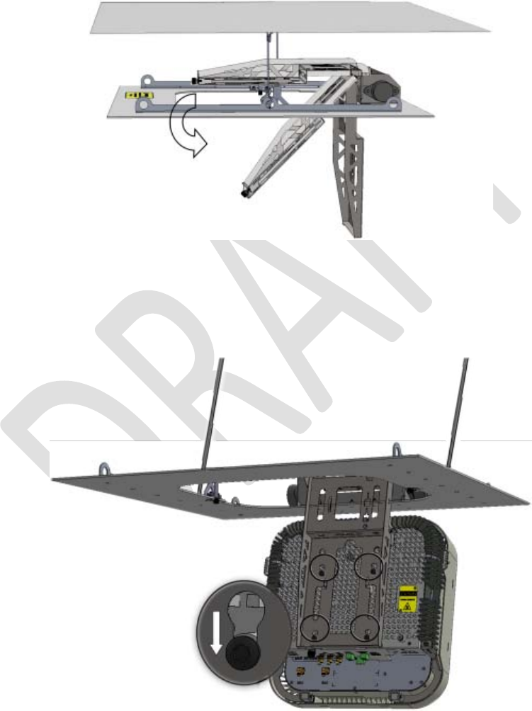
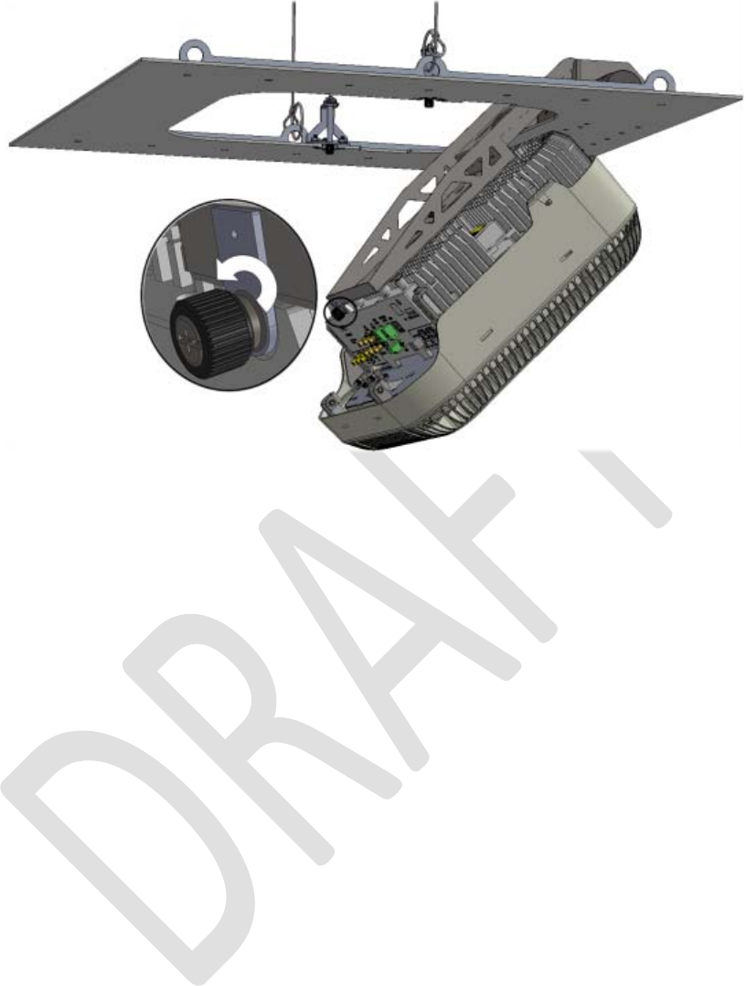
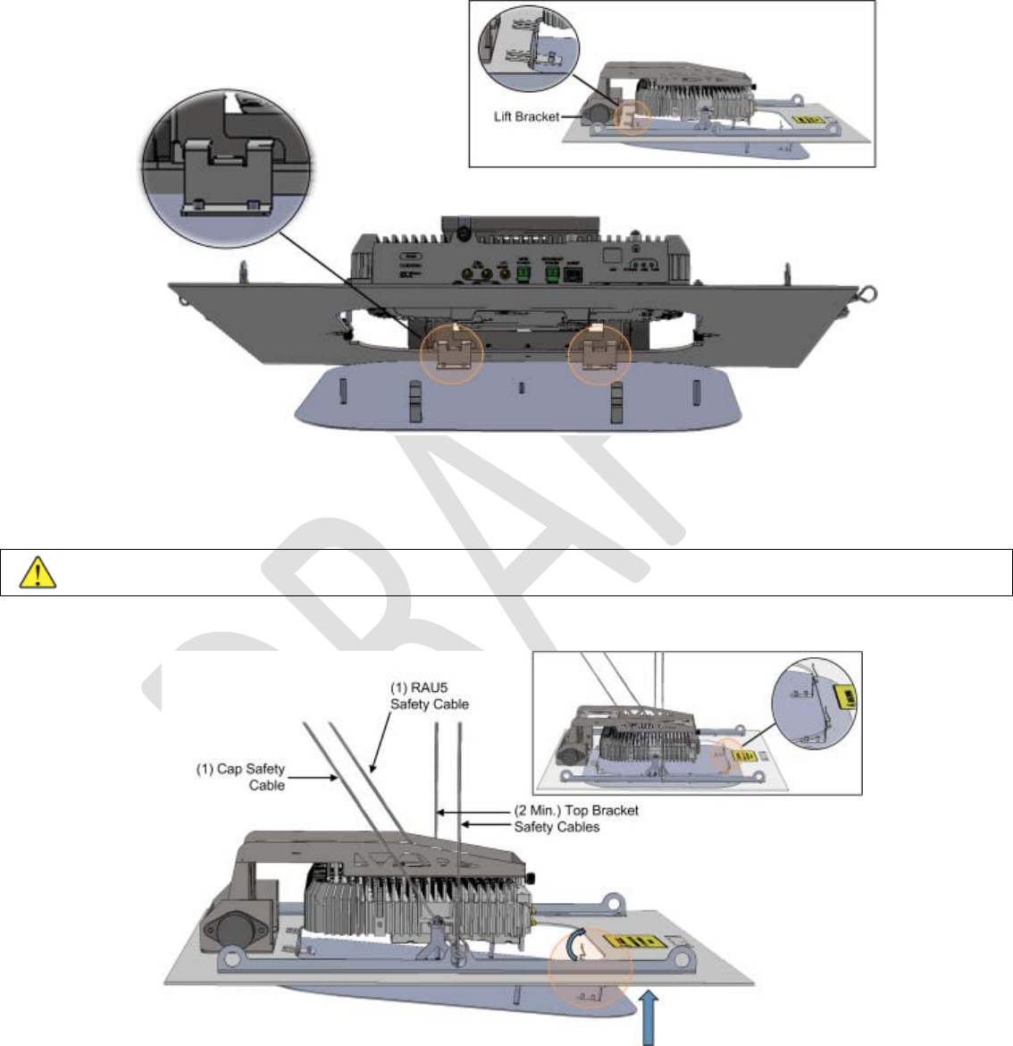
2. (After plate is installed in ceiling) Pull down the Lift Bracket to a vertical position.
Figure 4-7. Lowering Lift Bracket
3. Referring to Figure 4-8, fit the four pins on the RAU5x underside into the wide end of “Lift Bracket” keyholes and pull down
into narrow ends to lock in. Make sure that the RAU5x is secure.
Note: Lift Bracket captive screw must face the RAU5x connectors.
Figure 4-8.Mounting RAU5x onto Lift Bracket
4. Close Lift Bracket captive screw to secure RAU5x in place.
Corning Optical Communications User Manual I CMA-482-AEN I Page 37
Figure 4-9 Closing Lift Bracket Captive Screw
Note: it is recommended to perform the RAU5x connections after the unit is secured to the Lift Bracket.
Corning Optical Communications User Manual I CMA-482-AEN I Page 38
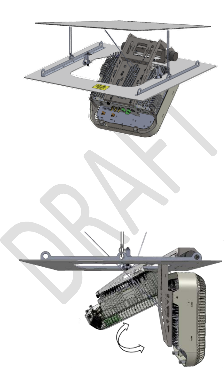
5. MANDATORY! Secure RAU5x using the attached safety cable to a permanent structure.
Figure 4-10. Securing RAU5x to Permanent Structure
6. Push up and pull down Lift Bracket into plate and verify that connection cables are not subject to kinking.
Note: The installer is solely responsible for proper cable wiring and routing of the RAU5x unit per instructions provided in
relevant Corning documentation.
Figure 4-11 Verifying that Cable Path is not Obstructed
Corning Optical Communications User Manual I CMA-482-AEN I Page 39
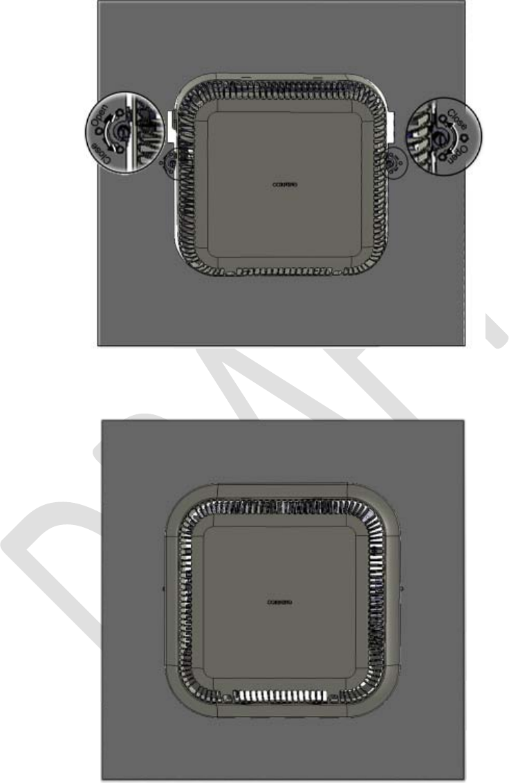
7. Lock “Lift Bracket” into plate - push RAU5x and Lift Bracket back up into plate and lock RAU5x into place by closing the
rotary knobs in the indicated direction.
Figure 4-12. Closing Rotary Knobs
8. Fit antenna skirt onto RAU5x.
Figure 4-13. Complete Assembled RAU5x
Note: Refer to Section
4.2.2.3for RAU5x top bracket cap assembly (kit ordered separately) for RAU5x units without Corning
external antenna.
Corning Optical Communications User Manual I CMA-482-AEN I Page 40
4.2.2.3 Top Bracket Cap Assembly
This section provides instructions on how to assemble the cap onto an installed RAU5x and “Top Bracket” assembly which does
not include the Corning plug-in external antenna.
Note the following:
• Cap, RAU5x and Top Bracket are each ordered separately.
• ATTENTION! In addition to the RAU5x and Top Bracket, the cap must also be secured to a permanent structure using the
provided safety cable!
• The cap complies with the 3-in clearance requirement above and below the RAU5x to allow airflow cooling.
Package contents
The BR-TOP-CAP kit consists of the cap for the RAU5x Top Bracket kit.
Figure 4-14. BR-TOP-CAP
Additional required items (not provided)
• RAU5x Top Bracket - for installing RAU5x in acoustic ceilings: BR-RAU5US-TOP (ordered separately)
• RAU5x without plug-in external antenna: RAU5XUS and RAU5XUS-E (ordered separately)
Corning Optical Communications User Manual I CMA-482-AEN I Page 41
To assemble the cap
1. Hook wide fasteners onto top bracket plate. Note that the wide fasteners face towards the base of the lift bracket.
Figure 4-15. Hooking Cap to Top Bracket plate
2. Lift up cap and hook narrow fasteners onto top bracket plate.
IMPORTANT! Before closing cap make sure to secure it to a permanent structure in the ceiling!
ATTENTION! The site engineer or contracted installer is responsible for all safety issues and procedures on-site!
Figure 4-16. Hooking Narrow Fasteners in Place
To remove the cap
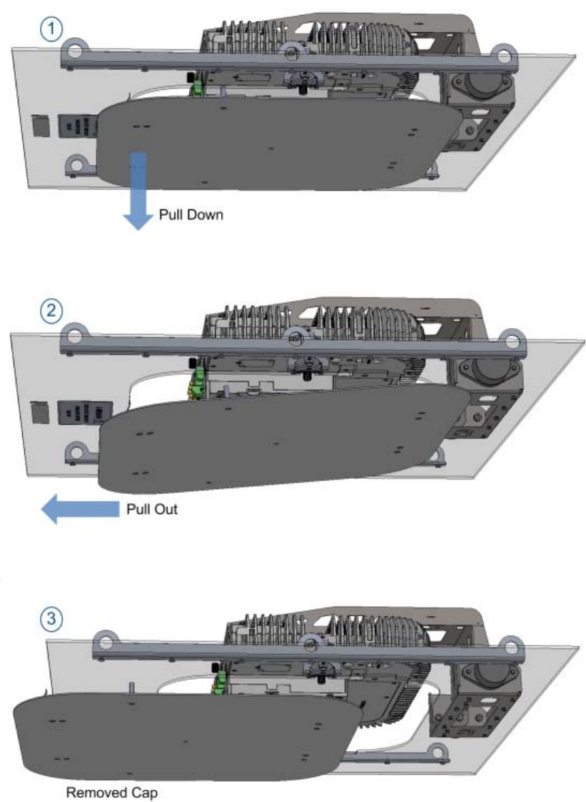
Corning Optical Communications User Manual I CMA-482-AEN I Page 42
Refer to following figures for instructions on how to remove cap in order to access the RAU5x.
Figure 4-17. Removing Cap
Corning Optical Communications User Manual I CMA-482-AEN I Page 43
4.2.3 Wall Mount
This section provides instructions on how to assemble up to two RAU5x units onto the wall-mount bracket and mount assembly
onto wall.
General Information
• The instructions provided are intended for concrete/brick walls.
• The RAU5x wall-mount bracket is only used with RAU5x models not including the preassembled external antenna:
• RAU5XUS
• RAU5XUS-E
WARNING: The site engineer or contracted installer is responsible for all safety issues and procedures on-site.
4.2.3.1 Package Contents
The BR-RAU5US-WALL kit consists of the wall-mount bracket and two standard RAU5 brackets preassembled onto each side
of the wall-mount bracket door.
Item
Quantity
Wall-mount bracket
Note: Refer to pg. 5 for wall-
mount
bracket dimensions.
1
Standoff mount (preassembled
onto each side of the bracket door)
2
Drilling template – used for marking
holes for drilling
1
Table 4-2. BR-RAU5US-WALL Kit Package Items
Corning Optical Communications User Manual I CMA-482-AEN I Page 44
Additional required item (not included):
¼ in bolts (x7) for mounting bracket on wall
4.2.3.2 Installing Wall Mount Bracket and Mounting RAU5x
3. Using the provided drilling template, mark a minimum of four holes to mount the bracket (if drilling only four holes, mark the
four outer corner holes).
Note: Image of drilling pattern with required distances also appears in Appendix A: Bracket Dimensions.
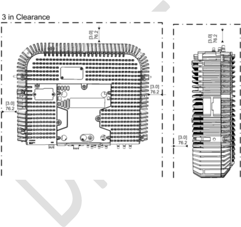
IMPORTANT! RAU5x requires 3 in clearing from the surface on the back and front, top and bottom to allow for proper cooling
airflow and for heat dissipation.
Figure 4-18. Required Three IN Clearance from Surface
Corning Optical Communications User Manual I CMA-482-AEN I Page 45
4. Align bracket with marked holes and drill anchors through bracket keyholes.
ATTENTION! The installer is responsible for accommodating the installation to the surface type.
Note: Insert the bolts in anchors and tighten until bolt head is 0.5” in from surface of wall.
Figure 4-19. Drilling Anchors through Wall-Mount Bracket Keyholes
5. Hang bracket on anchors and tighten.
Figure 4-20. Mounting and Securing Bracket to Anchors
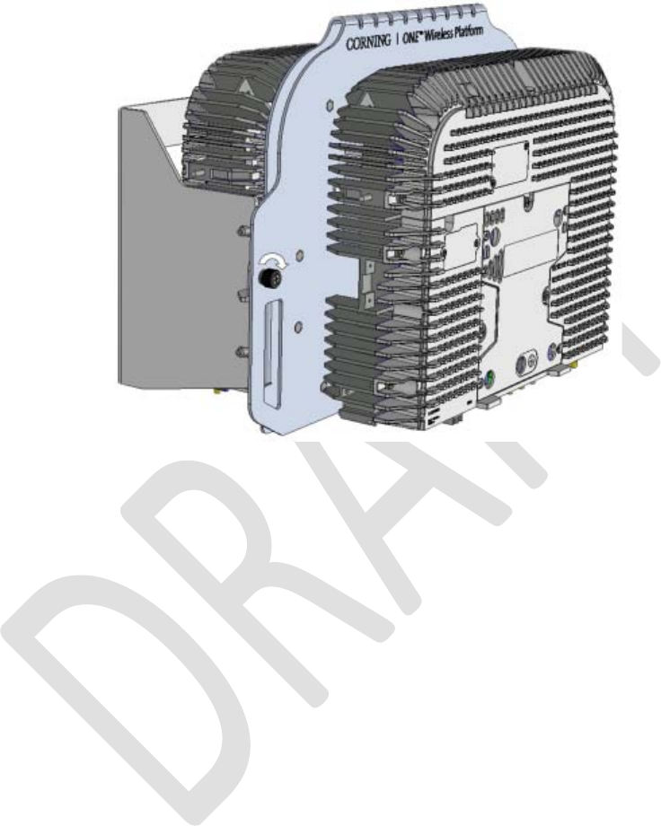
6. Mount RAU5x on standoff mount and close captive screw to secure RAU5x to bracket.
Corning Optical Communications User Manual I CMA-482-AEN I Page 46
Figure 4-21. Mounting and Securing RAU5x Unit
7. For Second RAU5 – mount on second standoff mount and close captive screw to secure RAU5x to bracket.
Figure 4-22. Mounting and Securing Second RAU5x
Corning Optical Communications User Manual I CMA-482-AEN I Page 47
8. Open and close bracket door to verify clearance for routing and connecting cables.
Note: Installer is solely responsible for proper cable wiring and routing of the RAU5x unit per instructions provided in relevant
Corning documentation.
9. Lock wall-mount bracket door.
Figure 4-23. Locking Wall-Mount Bracket Door
Corning Optical Communications User Manual I CMA-482-AEN I Page 48
4.3 Connections
Note: This section references RAU5x, however connections are performed the same for RAU5 and RAU5x models.
4.3.1 Locate Required Connection Cables
Locate the following connection cables leading from the cable infrastructure:
• DC wiring:
• One pair for MAIN POWER connection
• One pair for SECONDARY POWER connection (for RAUx models including GEM module)
• Fiber pairs (Corning SMF-28® fiber or compatible):
• One fiber pair for RAUx module
• One fiber pair for GEM module (for RAUx models including GEM)
• Grounding wire
For RAU5x models not including external antenna – RF jumper cables from installed external antenna
4.3.2 Cable Connections
Route the ground, RF and fiber cables located in Section 4.3 between the standoff mount bracket and the RAU5x towards the
interface connectors.
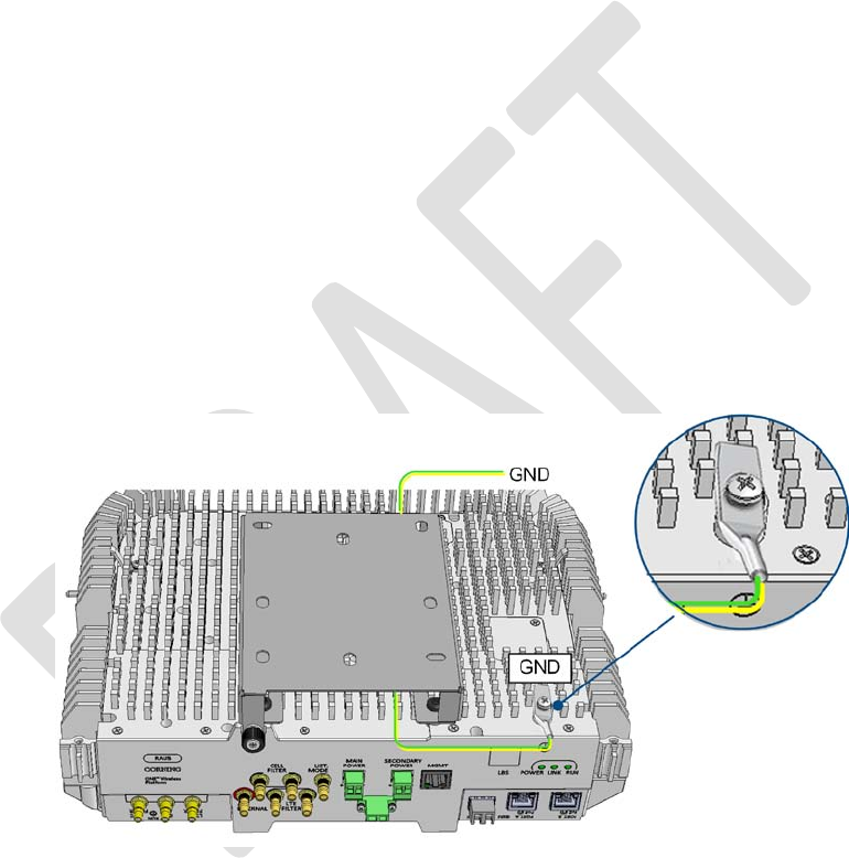
4.3.2.1 Grounding Connection
Connect the earth ground to the RAU5/RAU5x 8-32 x 3/8 grounding screw. See Figure 4-28 for example of RAU5x ground
connection.
Figure 4-24. RAU5/RAU5x Grounding Connection
Corning Optical Communications User Manual I CMA-482-AEN I Page 49
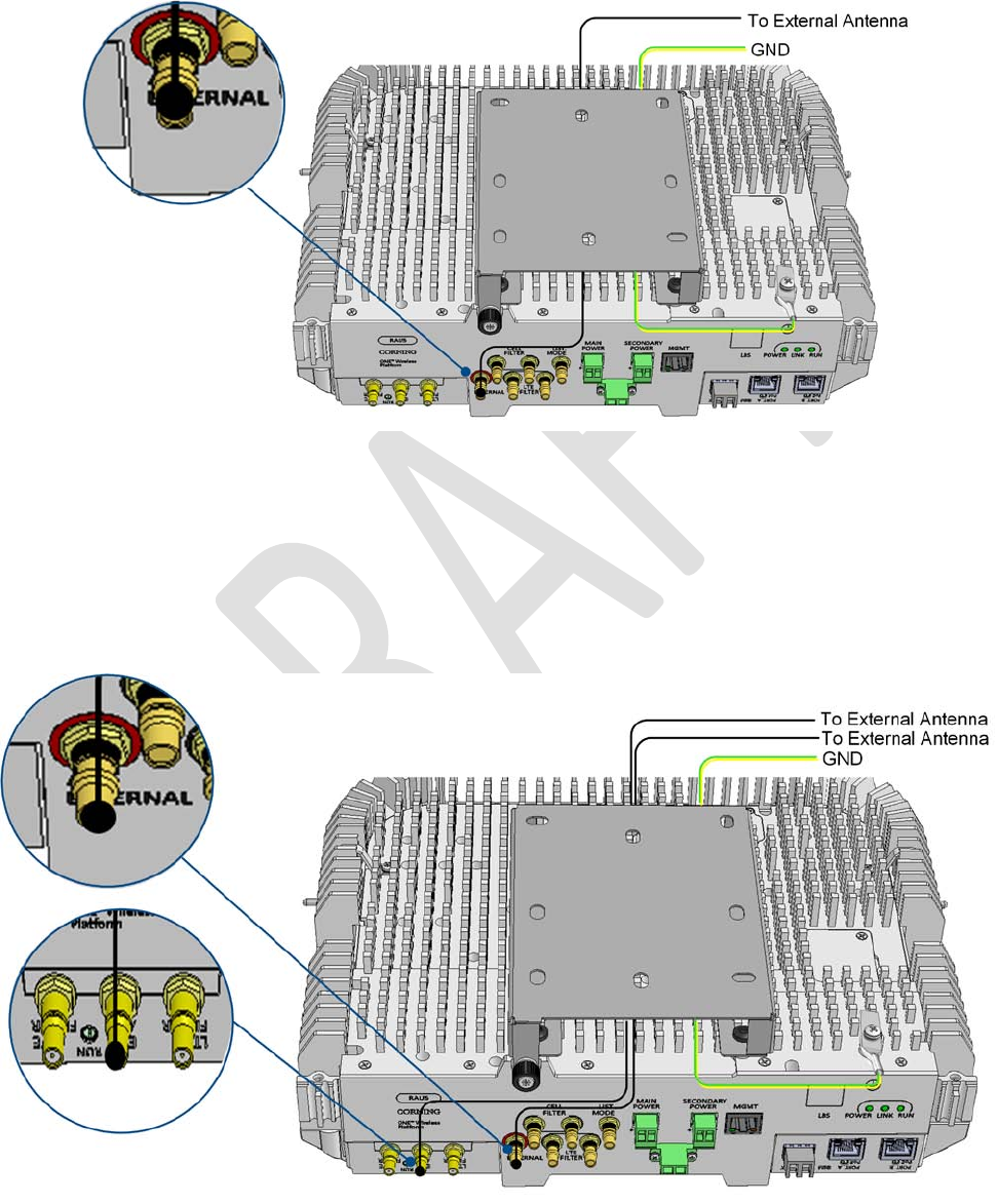
4.3.2.2 RF Connections
1. For RAU5x models not including Corning external antenna – connect the RAU5x QMA “Ext. Ant.” connector to the external
antenna, as illustrated in Figure 4-25. Note that for RAU5x units installed with RxU2325, the external antenna is connected
to the RxU2325 “ANT.” port.
Figure 4-25. RAU5/RAU5x External Antenna Connection
Note: See Section
3.6
3.6.1 for supported external antenna types.
2. Add-on connections (i.e., RxU/RxU2325):
For RAU5/RAU5x with RxU:
• Connect RxU “Ext. Ant.” QMA port to external antenna
Figure 4-26. RAU5/RAU5x with RxU - External Antenna Connections
Corning Optical Communications User Manual I CMA-482-AEN I Page 50
• If required by site planner – perform (QMA) connections to CELL and/or LTE external filters. Refer to Section 4.5 for
details on filter connections.
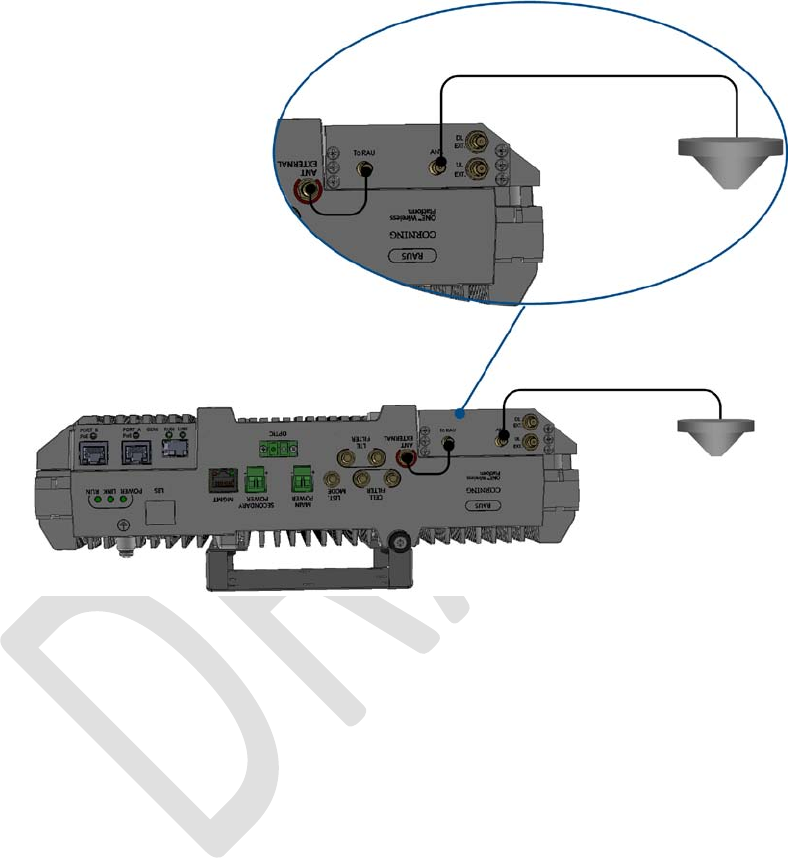
For RAU5x with RxU2325:
• Connect the RxU2325 “ANT.” QMA connector to the external antenna.
• Using the RF jumper (P/N 705A052301), supplied with the add-on, connect the RxU2325 “To RAU” QMA connector to
the RAU5x “ANT External” QMA connector.
Figure 4-27. RF Connections for RAU5x with RxU2325
• If required by site planner – perform (QMA) UL/DL external connections to external filters.
Corning Optical Communications User Manual I CMA-482-AEN I Page 51
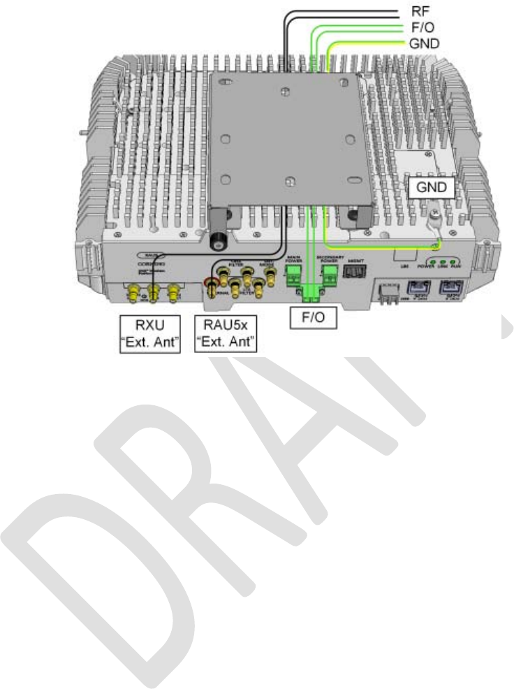
4.3.2.3 Fiber Connections
Connect optic fiber pair to RAU5x module LC APC optic connector. See Figure 4-28.
Figure 4-28. Ground, Fiber and RF Cable Connections for RAU5x
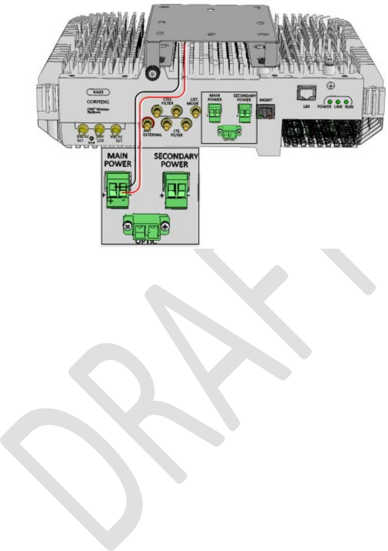
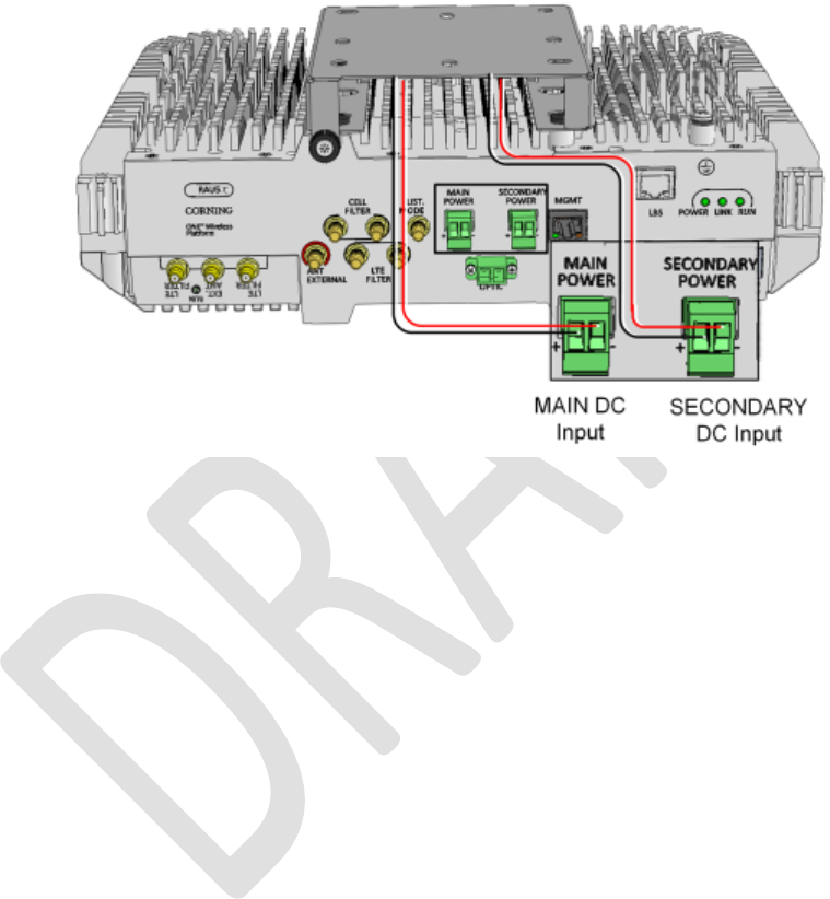
4.3.3 Main Power Connections
Note: The power consumption is the same for both RxU and RxU2325 modules.
RAU5x “MAIN POWER” (for RAU5x/RAU5x+RxU) DC input power connections (see Figure 4-29) – connect DC wire pair to the
terminal block connector:
• Power input range: 37 to 57 VDC
• Wire size: 12-30 AWG
• Maximum consumption:
• RAU5x: 44.5 V; 50 W
• RAU5x + RXU: 44.5 V; 76 W
Corning Optical Communications User Manual I CMA-482-AEN I Page 52
Figure 4-29 RAU5x Main Power DC Connections
Corning Optical Communications User Manual I CMA-482-AEN I Page 53
4.3.4 GEM Connections (for Configurations including GEMs)
1. Connect DC wire pair to the RAU5x Secondary Power DC input connector (see Figure 4-30):
• Wire size: 12-30 AWG
• Max. Consumption:
• GEM: 4 W (RAU5: 44.5 V ; 52 W; RAU5x + RXU + GEM: 44.5 V; 78 W)
• For 2 PoE ports of 802.3af: 43 V ; 31 W (Input range: 43 – 57 V DC)
• For 2 PoE ports of 802.3af: 52 V ; 62 W (Input range: 52 – 57 V DC)
Figure 4-30. RAU5x MAIN and SECONDARY DC Input Connections
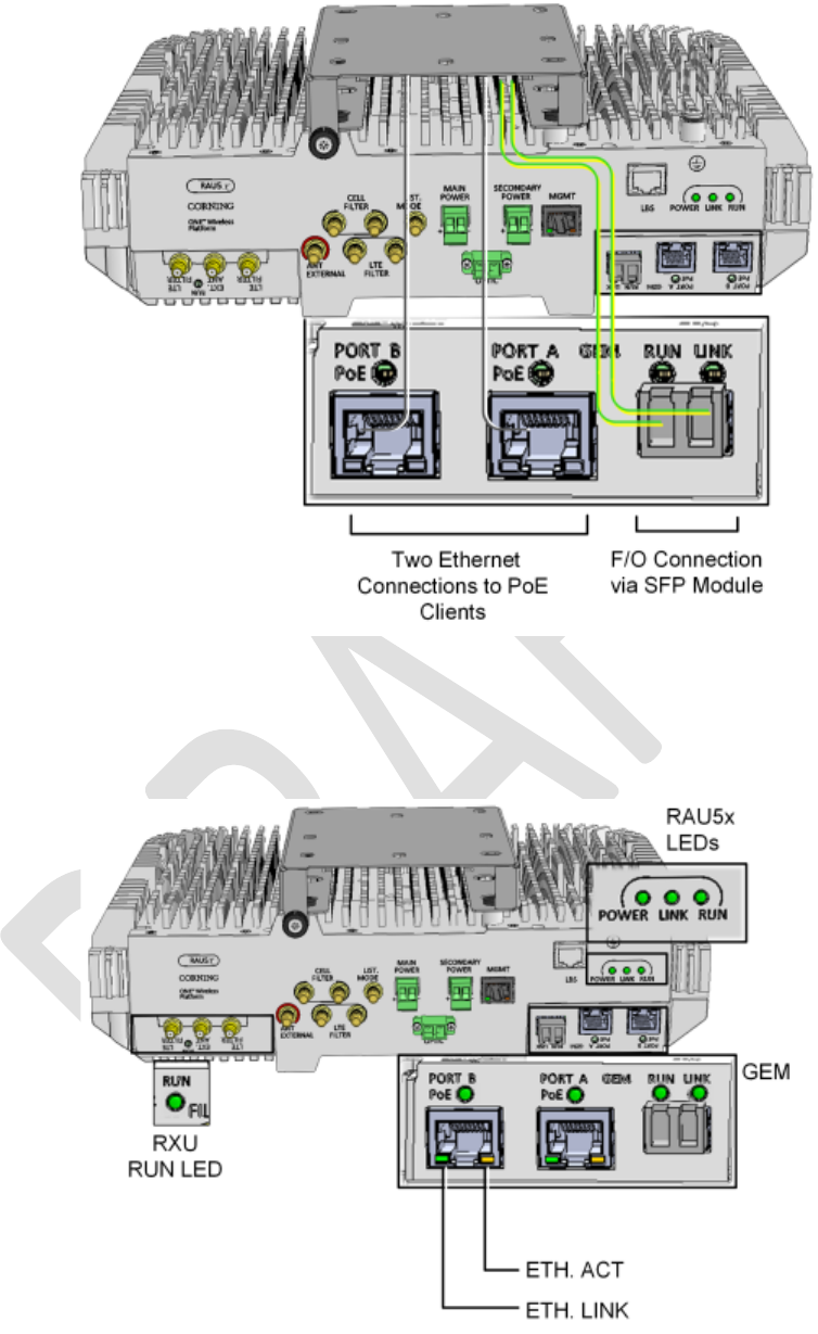
2. Connect fiber to SFP module ports as follows:
• If using fiber terminated with LC APC (green), connect to pre-inserted APC to UPC adapters
• If using fiber terminated with LC UPC connector (blue), remove pre-inserted APC to UPC adapters and connect directly
to SFP module ports.
3. Connect the A and B Ethernet ports to the PoE clients using Ethernet cables.
Note: A and B ports – 10/100/1000 BASE-T with 802.3at compliant Power over Ethernet (PoE+) PSE ports.
Corning Optical Communications User Manual I CMA-482-AEN I Page 55
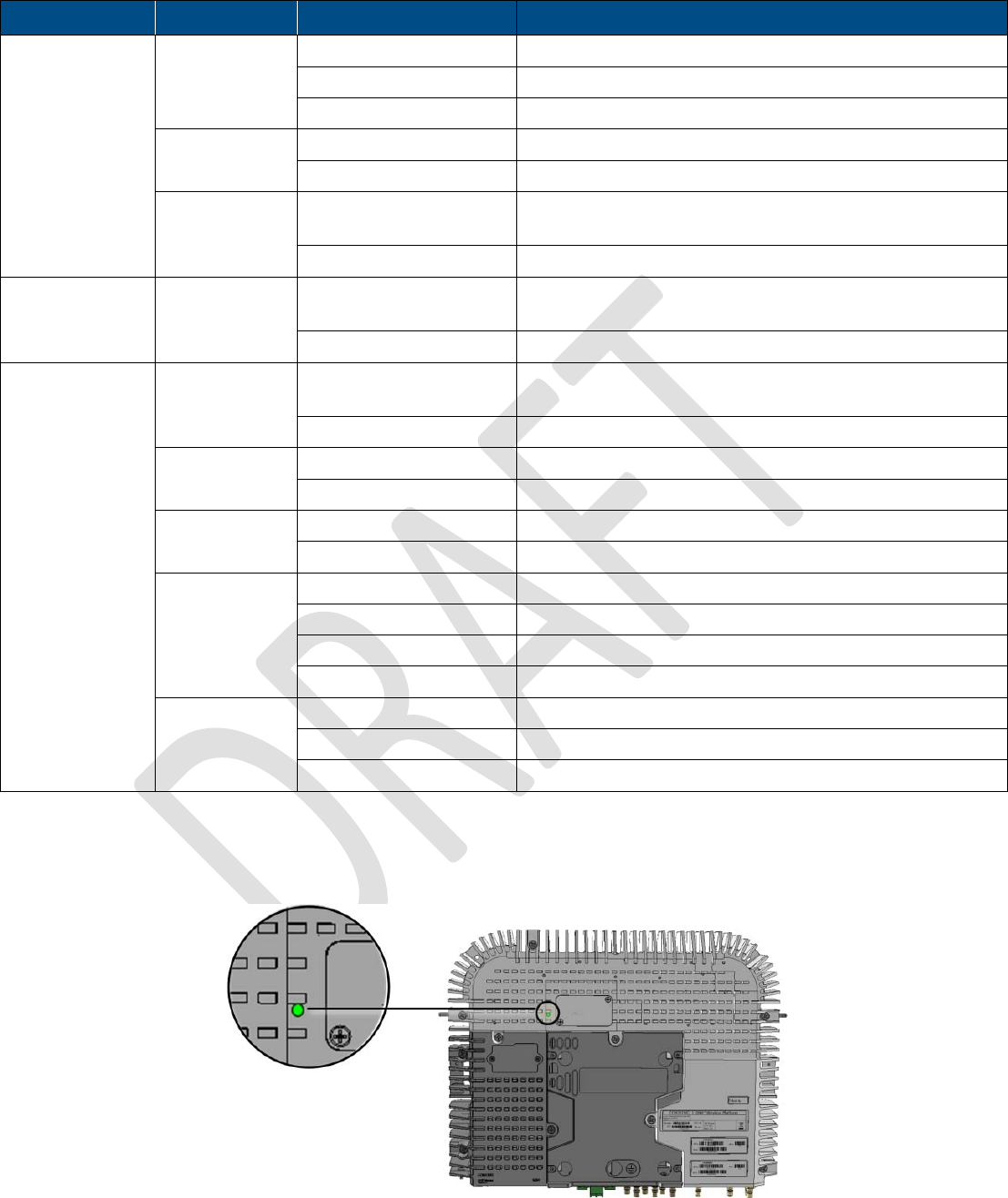
Module
LED
Description
RAU5x LINK Steady Green: Optical link power to/from the RAU5x is normal
Blinking Green: Optical power from remote is lower than required
Off: No optical link detected
POWER Steady Green: Input power detected by RAU5x
Off: No power supplied to RAU5x
RUN Blinking Green: RAU5x boot up sequence complete and module software
up and running
Off: No power supplied to the unit
RXU RUN Blinking Green: RXU boot up sequence complete and module software up
and running
Off: No power supplied to the unit
GEM (GEM)
RUN/STATUS
Steady Green (with short
blink every ~ 10 sec):
GEM On/Normal
Steady Yellow: GEM Fault
ETHERNET
LINK
Steady Green: Link
Off: No link
ETHERNET
ACT
Blinking Yellow: Activity
Off: No activity
(SFP) LINK Steady Green: Link
Blinking Green: Activity
Steady Yellow: Fault
Off: No link
(PortA/B) PoE Steady Green: PoE enabled
Steady Yellow: PoE fault
Off: PoE off
Table 4-3. Normal Operation LED Status Descriptions
The RxU2325 status LED is located on the top side of the module, as shown in Figure 4-33.Verify that the LED shows green,
indicating power and normal operation
Figure 4-33. RxU2325 Status LED Location
Corning Optical Communications User Manual I CMA-482-AEN I Page 56
4.5 RAU5x/RxU Cavity Filter Installation
Note: This section references RAU5x, however connections are performed the same for RAU5 and RAU5x models. The same
applies to RxU2325 connections to RAU5/RAU5x.
The external cavity filters are required when the RF services modules supporting the corresponding CELL and LTE bands are
deployed alongside units supporting the public safety service.
• The RAU5x supports connections to external CELL and LTE Filters
• The RXU supports connections to an external LTE Filter.
• In cases where an LTE External Filter is required and the RAU5x includes the RxU module – both modules must be
connected to an external LTE filter.
Note the following:
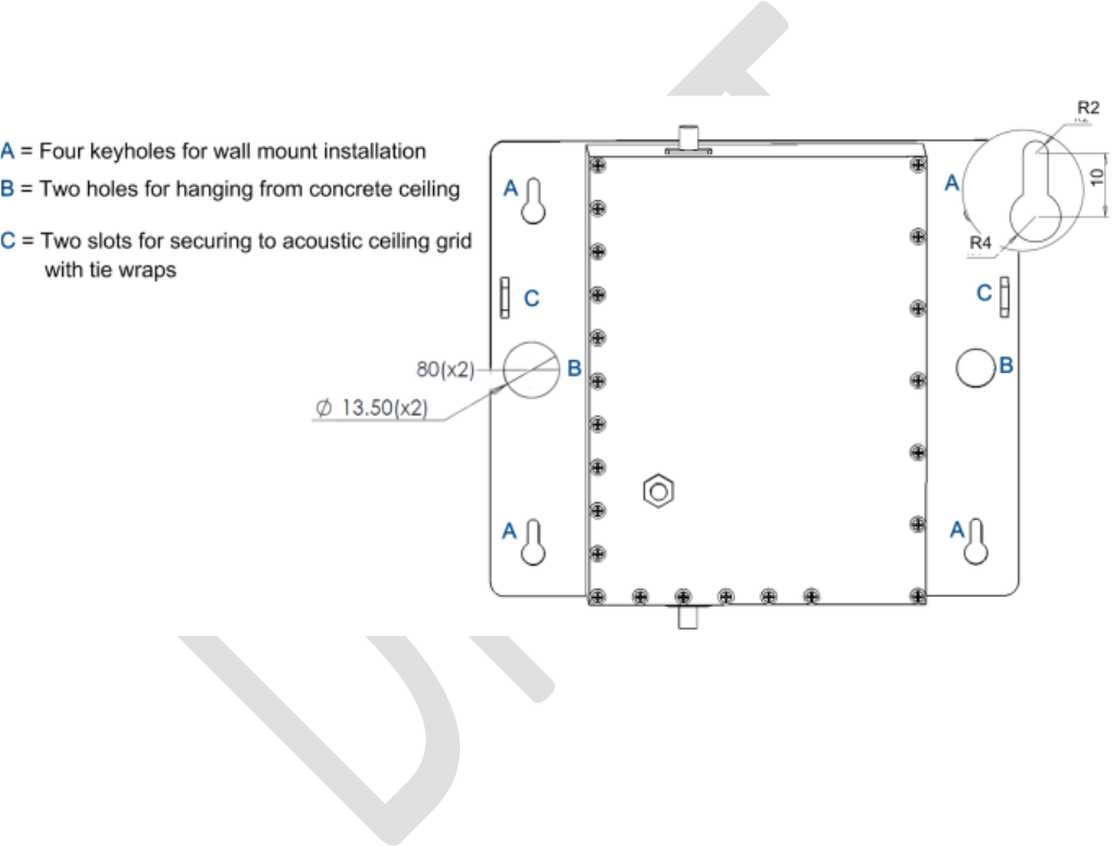
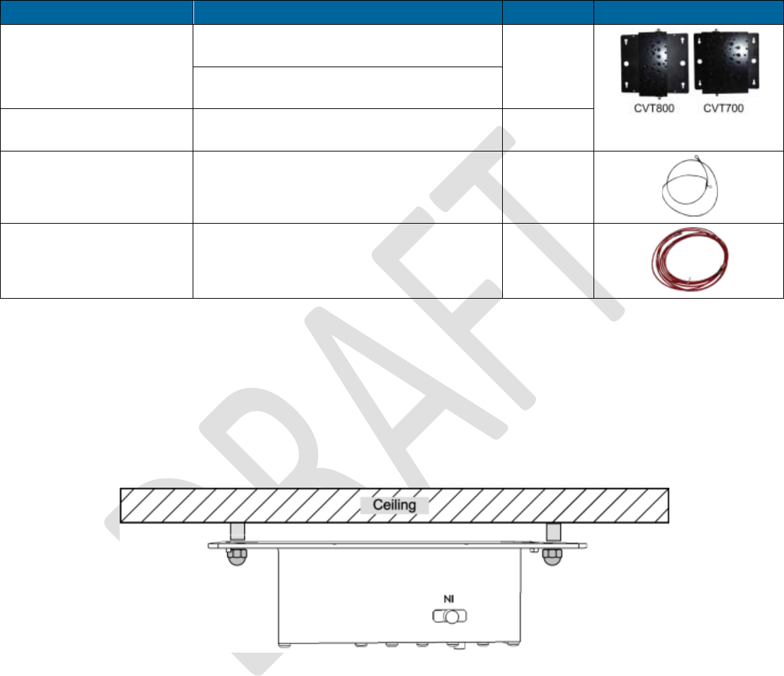
• The cavity filter mounting bracket supports wall/ceiling/acoustic ceiling installations. See Figure 4-34.
Figure 4-34.Cavity Filter Dimensions and Mounting Holes
• Consider the length of the RF jumpers (3 m) and the distance from the RAU5x when determining the installation location.
• For acoustic ceiling installations – use provided safety cable to secure the filter assembly to a permanent structure within the
ceiling (e.g., acoustic ceiling grid or concrete ceiling above).
Corning Optical Communications User Manual I CMA-482-AEN I Page 57
4.5.1 Package Contents
Check your package contents to verify that the items in the packing list are included. If any of the listed items are missing,
contact your Corning representative.
Item
Description
Quantity
Cavity Filter (depends on
order)
CVT800 - 836.5MHz; 0.5W; 824-849MHz;
IL=1.6 dB max.; SMA
1
CVT700 – LTE; 0.5W; 698-716MHz;
777-787MHz; IL=1.5 dB; SMA
Mounting Bracket Provides wall mount and ceiling mount
installation options (pre-assembled with filter)
1
Safety Cable Required for acoustic ceiling installations 1
RF Jumpers SMA to QMA RF jumpers; L=3m; Used for
RAUx/RXU filter connections
2
Table 4-4. Cavity Filter Package Items
4.5.2 (Concrete) Ceiling Mounting Option
To mount Cavity Filter on Concrete Ceiling
1. Using the two holes (Item B in Figure 4-34) as a guide, mark the location of the holes to be drilled in the ceiling.
2. Drill the holes in ceiling corresponding to the diameter of the toggle anchors to be used (not provided).
3. Mount the Cavity Filter as shown in Figure 4-35.
Figure 4-35. Illustration of Cavity Filter Mounted on Ceiling
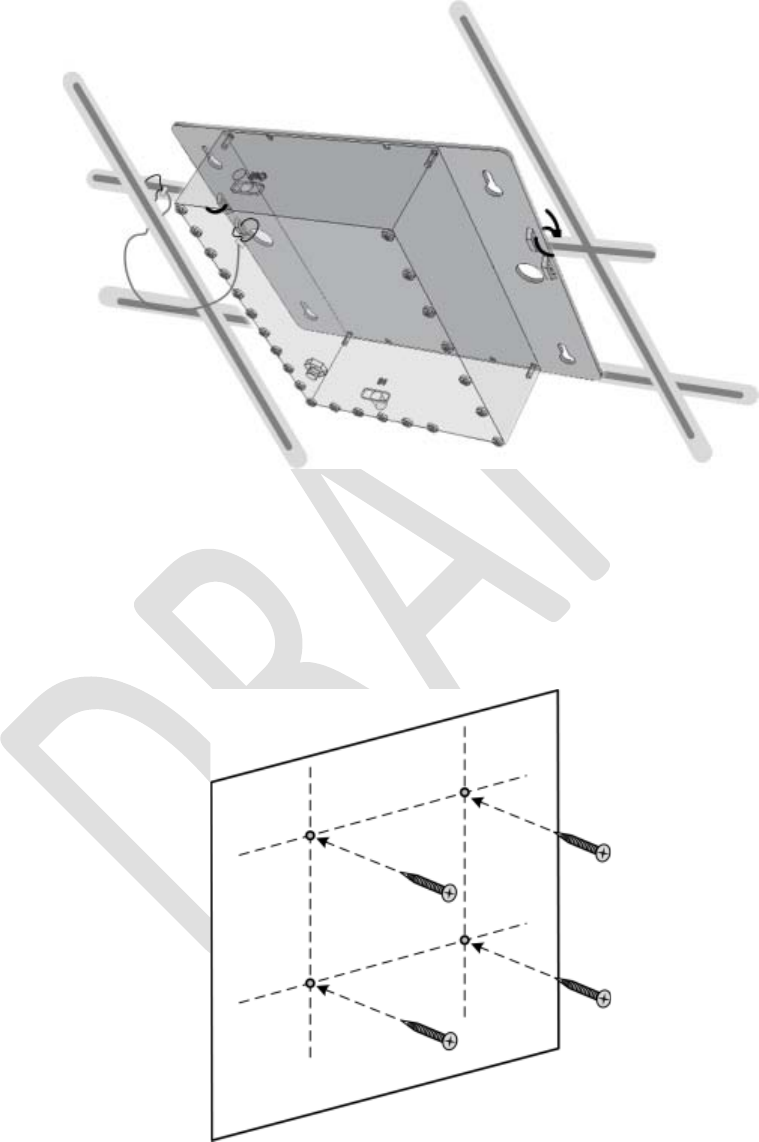
Corning Optical Communications User Manual I CMA-482-AEN I Page 58
4.5.3 Acoustic Ceiling Mount Installation
In acoustic ceiling mount installations, the Cavity Filter can be fastened to the grid by slipping tie wraps through slits on the
bracket (Item C in Figure 4-34) and securing the assembly to the grid with the provided safety cable. Refer to Figure 4-36.
Figure 4-36. Illustration of Cavity Filter Mounted on Acoustic Ceiling Grid
4.5.4 Wall Mount Installation
To mount Cavity Filter on Wall
1. Using the four key holes (Item A in Figure 4-34) as a guide, mark the location of the holes to be drilled in the wall.
2. Drill the holes in the wall corresponding to the diameter of the anchors to be used (not provided).
Figure 4-37. Marking and Inserting Anchors in Wall
3. Hang the Cavity Filter on the anchors/screws and pull down to lock in narrow end of key hole. Refer to Figure 4-38.
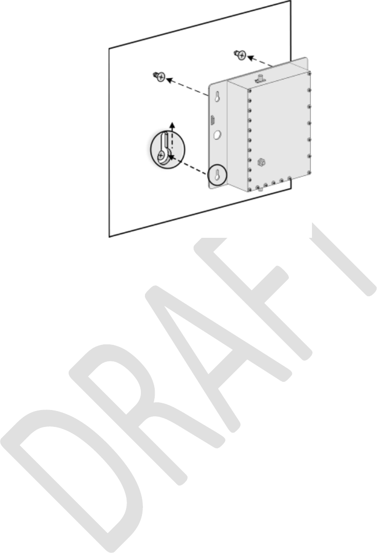
Corning Optical Communications User Manual I CMA-482-AEN I Page 59
Figure 4-38. Mounting Cavity Filter on Wall
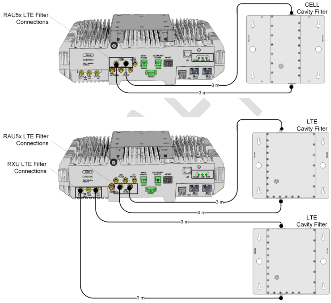
Corning Optical Communications User Manual I CMA-482-AEN I Page 60
4.5.5 Filter Connections
Using the provided SMA to QMA RF jumpers, connect the Cavity Filter IN and OUT QMA ports to the corresponding filter
(CELL/LTE) SMA connectors on the RF module.
Note: In installations where additional units are deployed which support the 700 MHz band and the RAU5x is installed with an
RXU – both RAU5x and RXU modules must be connected to an external LTE filter. See Figure
4-39 and Figure
4-40.
Figure 4-39. Example of RAU5x External CELL Filter Connections
Figure 4-40. Example of RAU5x and RXU External LTE Filter Connections
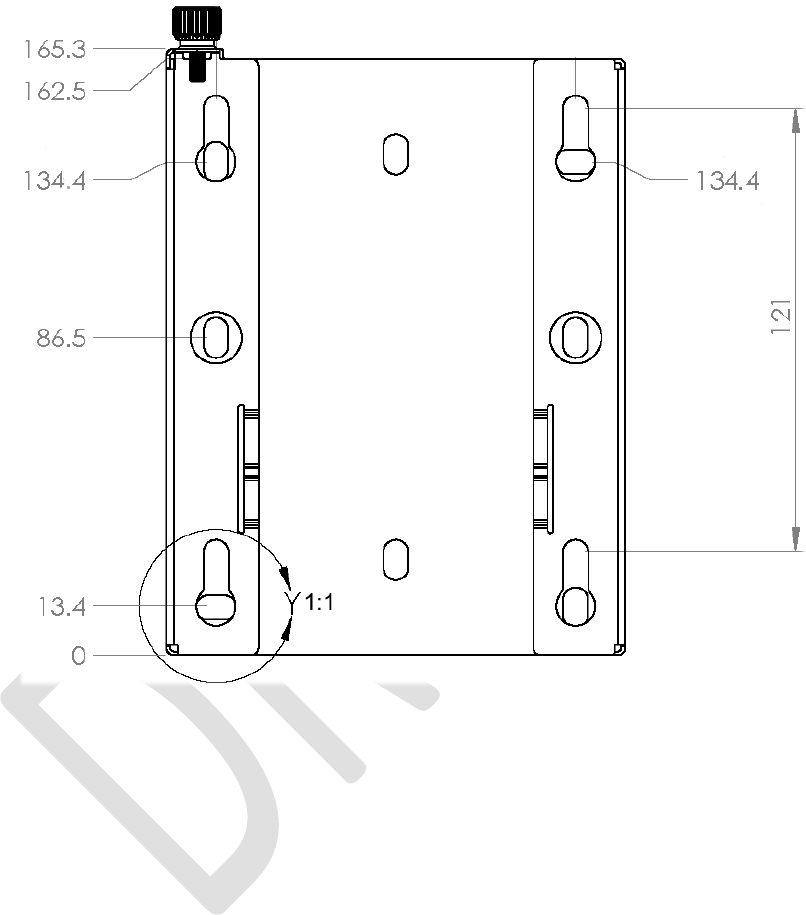
Corning Optical Communications User Manual I CMA-482-AEN I Page 61
5 Appendix A: Bracket Dimensions
Standoff Mount
Figure 5-1. Standoff Mount Dimensions
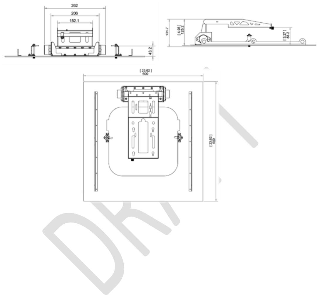
Corning Optical Communications User Manual I CMA-482-AEN I Page 62
Top Bracket
Figure 5-2 RAU5 Top Bracket Dimensions
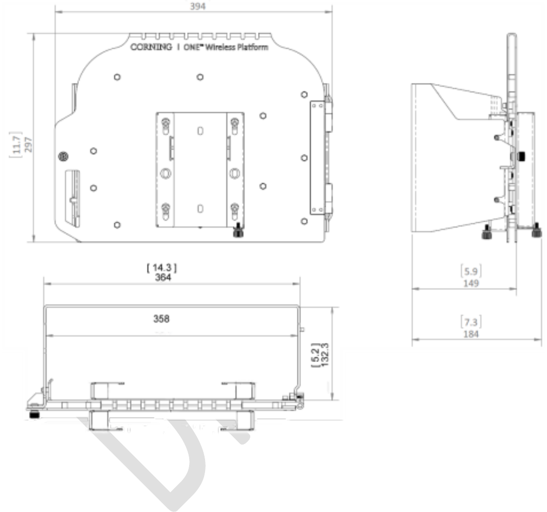
Corning Optical Communications User Manual I CMA-482-AEN I Page 63
Wall Mount Bracket
Figure 5-3. RAU5 Wall Mount Bracket Dimensions
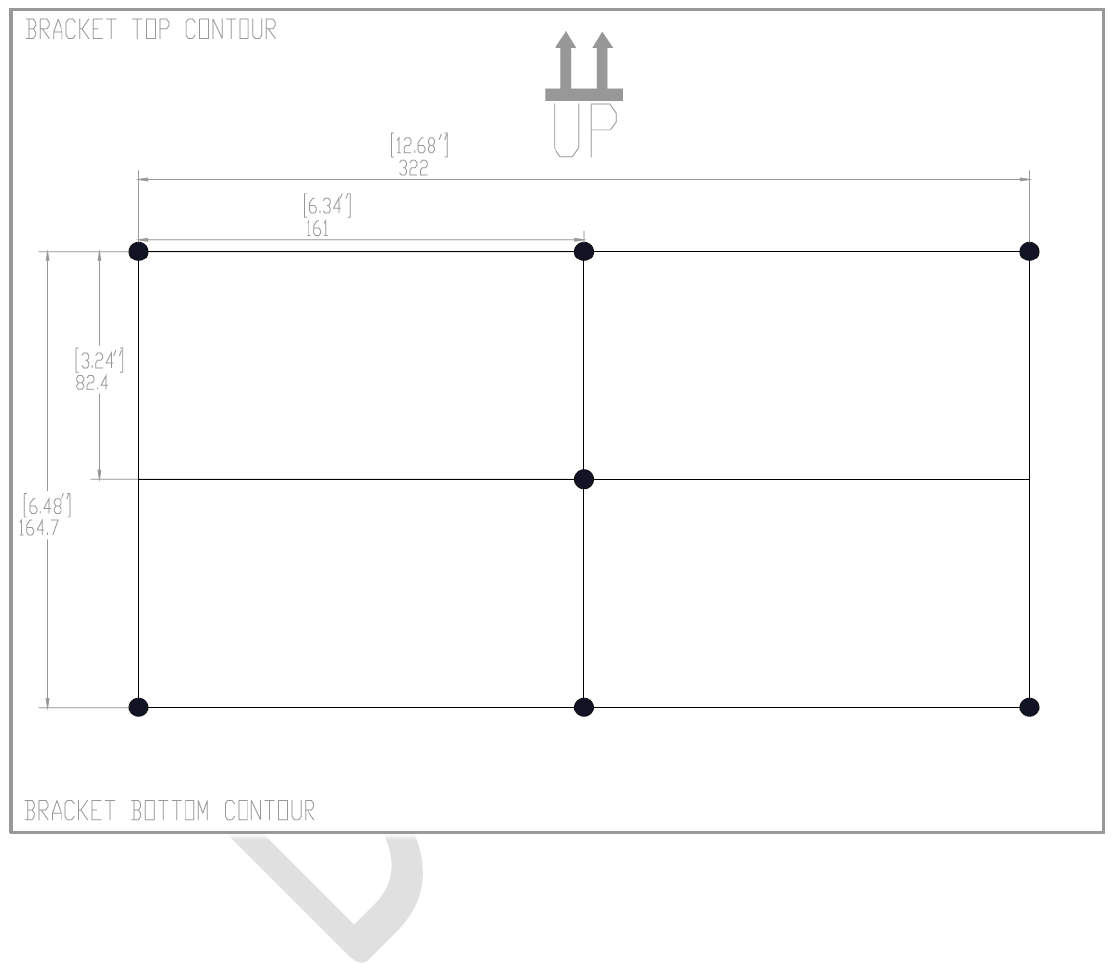
Corning Optical Communications User Manual I CMA-482-AEN I Page 64
Wall Mount Bracket - Drilling Pattern Dimensions
Note: The drilling pattern template is provided with the wall mount bracket kit (P/N: BR-RAU5US-WALL).
Figure 5-4. RAU5 Wall Mount Drilling Pattern Dimensions
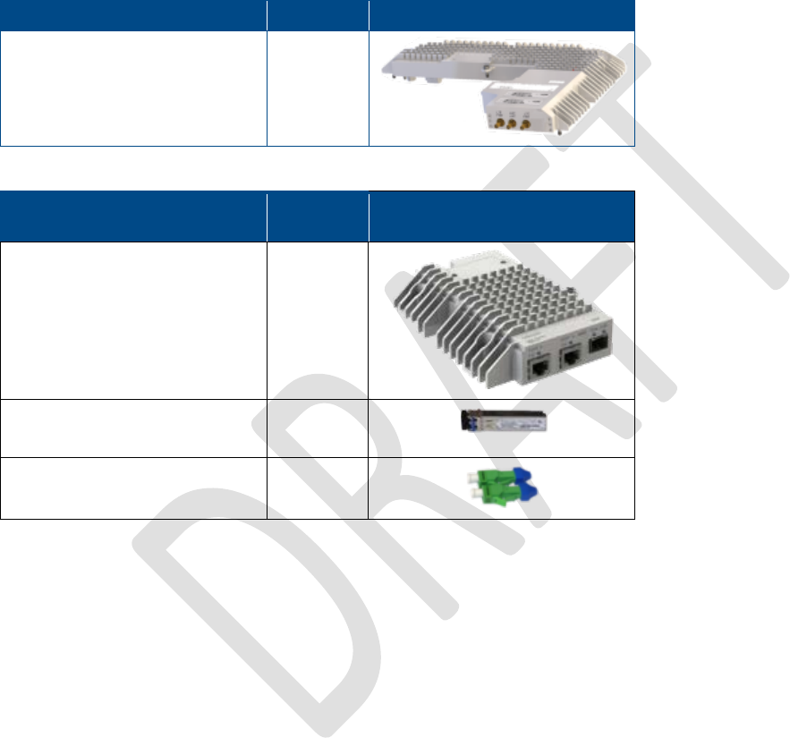
Corning Optical Communications User Manual I CMA-482-AEN I Page 65
6 Appendix B: Upgrades
This section describes how to upgrade the RAU5x (and RAU5) with an RxU, RxU2325, and/or GEM plug-in module for units’
ordered initially without these modules installed.
6.1 Package Contents
Each plug-in module is ordered separately. Check the package contents for external damage.
Item
Quantity
Image
Remote Expansion Unit (RXU) 1
Table 6-1. RXU Package Contents
Description
Quantity
Gigabit Ethernet Module
(GEM)
1
SFP – Fiber UPC Module
(pre-inserted)
1
UPC to APC Adapter 2
Table 6-2. GEM Package Contents
6.2 Installing the Plug-in Module in the RAU5x
General Information
• There is no need to dismount the RAU5x from mounting surface.
• The RxU/RxU2325 and GEM are hot-swappable and do not require disconnecting cables leading from the ceiling or power.
Before installing plug-in module
• For RAU5x units mounted with top bracket (described in Section 4.2.2):
• For installations with cap – remove cap (refer to Section 4.2.2.3)
• Pull the lift bracket down
• For RAU5x units with assembled broadband antenna – open antenna by pushing in on the pins on both sides of the antenna
cover and pulling on the side handles, as show in Figure 6-1.
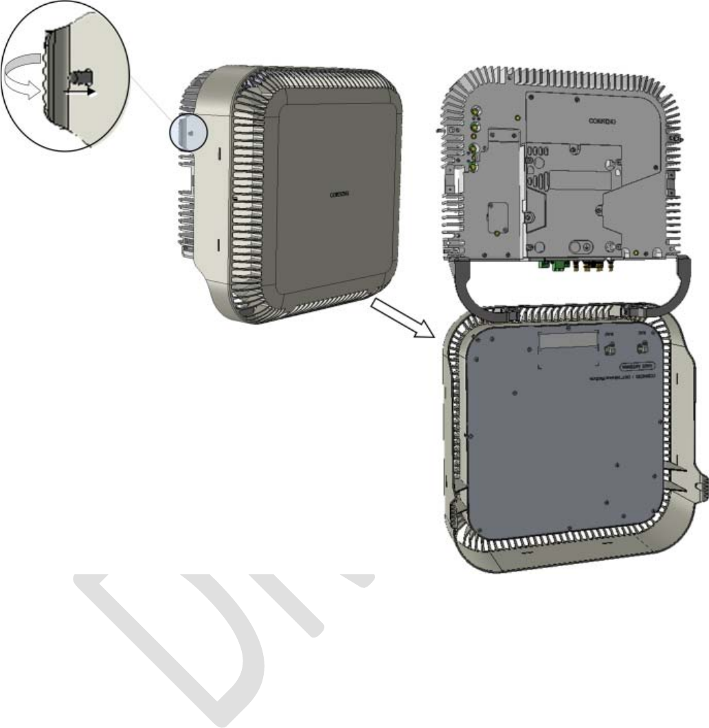
Corning Optical Communications User Manual I CMA-482-AEN I Page 66
Figure 6-1. Opening RAU5x Antenna
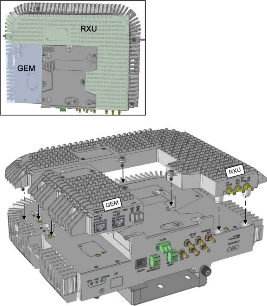
Corning Optical Communications User Manual I CMA-482-AEN I Page 67
To install plug-in module in RAU5x :
1. Plug-in module as follows:
• RxU/RxU2325 – plug-in RxU into right side of the RAU5x as indicated in Figure 6-2 (area highlighted in green in inset)
and close the two screws to secure in place.
• GEM - plug-in GEM into left side of the RAU5x as indicated in Figure 6-2 (area highlighted in blue in inset) and close the
screw to secure in place.
Figure 6-2. Plugging-in RxU and GEM
Corning Optical Communications User Manual I CMA-482-AEN I Page 68
2. For units with broadband antenna – close antenna.
3. For RxU/RxU2325:
• With external antennas from other vendor - connect RxU “EXT. ANT.” QMA connector to an external antenna for MIMO
coverage
• With Corning external antenna – connect RxU “EXT. ANT.” QMA connector to the external antennas’ “RXU” QMA port
using RF jumper.
Note: If cavity filter connections are required for the LTE 700 MHz band – refer to Section
4.5 for relevant connections.
4. For GEM - refer to Section 4.3.4 for GEM connections.
5. Verify that RAU5x LEDs on front panel indicate normal operation status:
LED
Description
LINK Steady green - Optical link power to/from the RAU is normal
Blinking green - Optical power from remote is lower than required
Off – No optical link detected
POWER Steady green - Input power within required range detected
Off – No power supplied to RAU
RUN Blinking green – RAU boot up sequence complete and module SW up and running
Off – No power supplied to unit
6. Table 6-3. RAU5x LED Descriptions
7. For units installed with top bracket – push lift bracket into place.
8. For units with top bracket cap – replace cap (see Section 4.2.2.3).
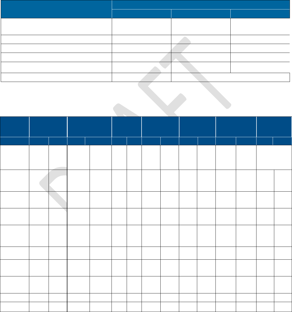
Corning Optical Communications User Manual I CMA-482-AEN I Page 69
7 Appendix C: Specifications
Supported Services
Technology
Frequency Range (MHz)
Service/Band
Uplink (UL)
Downlink (DL)
LTE 700 MHz Lower ABC
700 MHz Upper C
698-716
777-787
728-746
746-756
CDMA/WCDMA**/ TDMA/GSM/LTE* ESMR800/CELL850 817-824/824-849 862-869/869-894
WCDMA**/LTE* AWS1/3 1700 1710-1780 2110-2180
CDMA/WCDMA**/TDMA/GSM/LTE* PCS + G 1900 1850-1915 1930-1995
LTE WCS 2305-2315 2350-2360
LTE 2500 MHz TDD 2496 – 2690 (UL/DL combined)
*WCDMA service is based on 3GPP standards, LTE service may deployed in the future due to frequencies re-farming planned by the carriers as well
**WCDMA service is based on 3GPP2 CDMA2000 standards.
RF Parameters
Service/Band
LTE
700 MHz
ESMR800/
CELL850 MHz
PCS
1900 MHz
AWS
1700 MHz
AWS+AWS3***
1700 MHz
WCS
2300 MHz
LTE
2500 MHz TDD
RF Parameter
DL
DL
DL
UL
DL
UL
DL
UL
DL
UL
DL
UL
DL
UL
Frequency
Range (MHz)
728 - 746
746 - 756
698 -
716
777 -
787
862-869/
869-894
817-824/
824-849
1930 -
1995
1850 -
1915
2110 -
2155
1710 -
1755
2110 -
2180
1710 -
1780
2350 -
2360
2305 -
2315
2496 - 2690
Maximum
Output Power
Per Antenna
Port (dBm)
15
15
20
18
20
18
(min)****
18
(min)****
Maximum
Input Power
(dBm)
0 to 37 -10 to 37/
0 to 37
0 to 37
0 to 37 0 to 37 0 to 37 0 to 37
Typical
Antenna Gain
(dBi)
0 0.5 3 2.5 2.5 2.5 2.5
Horizontal
Polarization
Omni @ 34-45
Degree
-2 to 0
-2 to 0
-1 to 1
-1 to 1
-1 to 1
-1 to 1
-1 to 1
UL Gain (dB)
-19 to 15
-19 to 15
-19 to
15
-19 to 15
-19 to 15
-19 to 15
-19 to 15
Input IP3
(dBm) AGC
OFF Typical
-5
-5
-5
-5
-5
-6
-6
Input IP3
(dBm) AGC
ON Typical
5
5
5
5
5
5
5
SFDR* (dB)
60
64
64
60
60
60
60
Maximum
Intermod
-13
-13
-13
-13
-13
-13

Corning Optical Communications User Manual I CMA-482-AEN I Page 70
Distortion
[dBm]
UL NF
**
(dB)
12 12 12 12 12 12 12
Gain
Flatness/Rippl
e (dB)
±2.0
±2.0
±2.0
±2.0
±2.0
±2.0
±2.0
* SFDR calculated with bandwidth of 1.23 MHz for the CELL and PCS and with 5 MHz for the LTE and AWS
**Typical for single remote access unit
***AWS3 supported by RAU5x models only.
****20 dBm if only one of the services is operating.
Optical
Optical Output Power
< 9 dBm
Max. Optical Budget
5 dB
Back Reflectance
- 60 dB
Optical Connector
LC APC SM
Fiber Type
Corning® SMF-28® fiber or compatible
Wavelength
1310 ± 10nm (@ 25◦ C)
Environmental Specifications
Operating Temperature 0°C to +50°C (32°F to 122°F)
Storage Temperature -20°C to 85°C (-4°F to 185°F)
Standards and Approvals
Laser Safety FDA/CE 21 CFR 1040.10 and 1040.11 except for deviations pursuant to laser notice no.
50 and IEC 60825-1
Class 1M (applicable to FMM/FRM)
EMC CE EN 301 489, EN55022, EN 61000
FCC 47 CFR Part 15, 22, 24, 27
Safety UL 60950
IEC 60825-1:2007
IEC 60825-2:2010
CAN/CSA-C22.2 No.60950-1-03
Fire Safety UL 2043
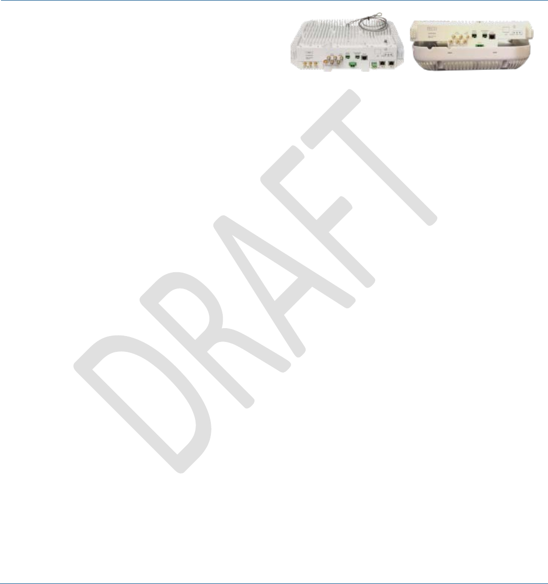
Corning Optical Communications User Manual I CMA-482-AEN I Page 71
Component Specifications
5 Band Remote Access Unit (RAU5/RAU5x)
RAU5/RAU5x hosts the following modules:
1. RXU; Remote expansion module, for additional LTE and
AWS MIMO service. One module per RAU5/RAU5x.
2. GEM; Giga bit Ethernet module – upgrade module for the
RAU5/RAU5x. One module per RAU5/RAU5xGEM;
Interface Connections
Two LC APC SM fiber connectors; UL and DL
Two DC power inputs ports; main and secondary in case of PoE clients
Two QMA RF ports; for External cavity filter (In/Out) use -LTE and CELL filters
One broadband external antenna QMA connector (connected antenna must have a
return loss of 12 dB)
One RJ-45 MGMT (local) connection
RXU module interface – power, digital and RF
GEM module Interface – power and digital
Antenna
Omni-Directional (15◦ down from horizon)
Power Consumption
For Main Power Input:
Input Range: 37-57 VDC
RAU5/RAU5x only: 44.5 V; 50 W
RAU5/RAU5x + RXU: 44.5 V; 76 W
RAU5/RAU5x + GEM: 44.5 V; 52 W
RAU5/RAU5x + RxU + GEM: 44.5 V; 78 W
For Secondary Power Input:
For 2 PoE ports of 802.3af: 46 V; 31.5 W (Input range: 43 - 57 V DC)
For 2 PoE ports of 802.3at: 52.5 V; 62 W (Input range: 52 - 57 V DC)
Management
Managed via the headend control module (HCM ):
• RAU5: software v1.3 and higher
• RAU5x: software v1.9 and higher
Physical Characteristics
(Enclosure and Modules)
Mounting:
Wall/ceiling (Horizontal mount)
Mounting bracket included in the installation kit
Mid-mount (acoustic ceiling) – separately ordered kit
Dimensions (H x W x D):
Without external antenna: 3.6* x 12.9 x 10.4 in (90 x 327 x 264 mm)
*3.6 in (90 mm) without standard mounting bracket; 4.4 in (111 mm) with standard mounting bracket
With external antenna and skirt: 6.1 x 13.1 x 13.1 in (154 x 338 x 338 mm)
Weight
(applies to both RAU5/RAU5x)
:
RAU5x only (no external antenna or plug-in modules): 10 lbs (4.5 kg)
RAU5x and RXU and GEM only: 14.39 lbs (6.5 kg)
External Antenna: 3.7 lbs (1.7 kg)
Environment
Ambient Temperature:
Wall-mount installations: 45◦C (113◦F)
Ceiling-mount installations: 50
◦
C (122
◦
F)
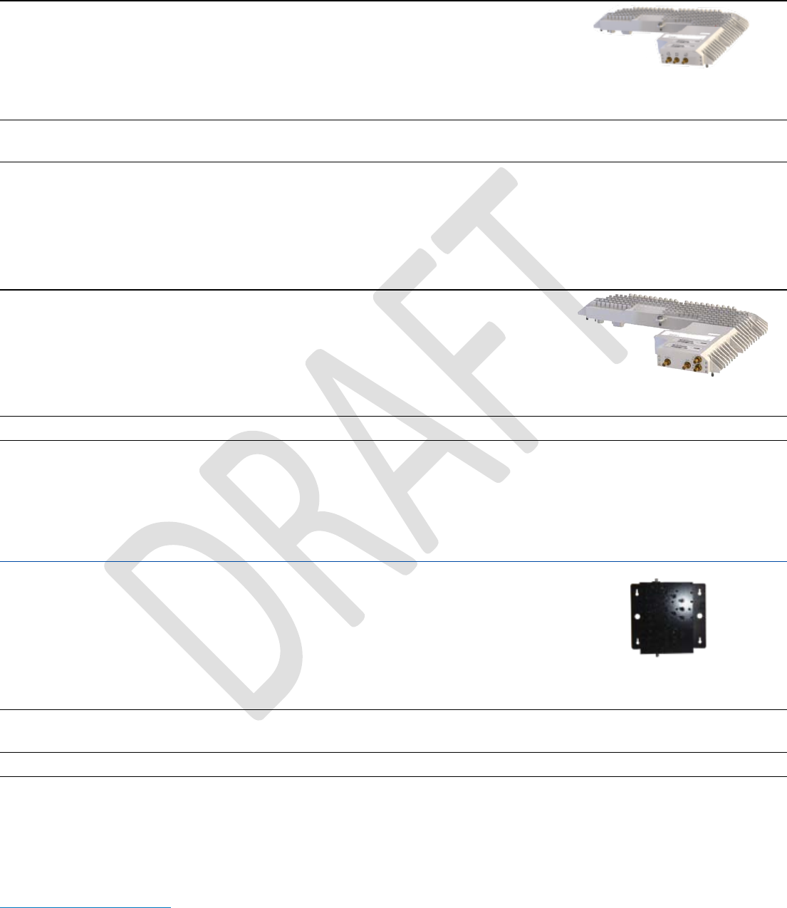
Corning Optical Communications User Manual I CMA-482-AEN I Page 72
Remote Expansion Unit (RxU)
Supported Services
Upgrade module supporting two services
AWS MIMO and LTE 700 MIMO
Interfaces
Three pins for integration with RAU5/RAU5x(power, control
and RF)
Management
Management via host
RAU5/RAU5x
Physical Characteristics
Mounting: Plugs into RAU5/RAU5x
Dimensions
(H x W x D):
1.09 x 12.8 x 9.8 in
(27.7 x 327.5 x 250 mm)
Weight: 3.08 lbs (1.4 kg)
2300 MHz/2500 MHz Remote Expansion Unit (RxU2325)
Services
Upgrade module supporting two services
2.3 GHz WCS and 2.5 GHz (LTE) TDD bands
Interfaces
Two QMA RF ports for external LTE and CELL cavity filter
connections
One broadband external antenna QMA connector
(connected antenna must have a return loss of 12 dB)
Management
Management via host RAU5x
Physical Characteristics
Mounting: Plugs into RAU5/RAU5x
Dimensions
(H x W x D):
1.09 x 12.8 x 9.8 in
(27.7 x 327.5 x 250 mm)
Weight: 3.08 lbs (1.4 kg)
Cavity Duplexer for LTE 700 MHz
LTE 700 MHz external cavity duplexer for RAU/RxU modules supporting the LTE band
and which are deployed alongside units supporting the public safety service.
Frequency Range
777 MHz ~ 787 MHz
Bandwidth
10 MHz
Insertion Loss
(Maximum)
1.5 dB
Passband Ripple
(Maximum)
0.8 dB
Return Loss (Minimum)
18.0 dB, all ports
Rejection
55 dB Min @ DC ~ 620 MHz
40 dB Min @ 698 MHz ~ 716 MHz
35 dB Min @ 728 MHz ~ 757 MHz
30 dB Min @ 765 MHz ~ 775 MHz
30dB Min @ 793 MHz ~ 1000 MHz
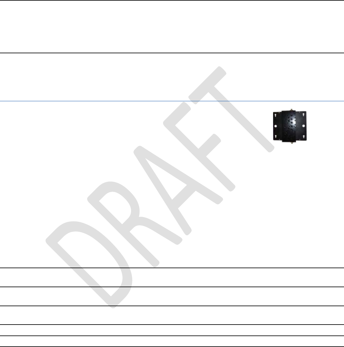
Corning Optical Communications User Manual I CMA-482-AEN I Page 73
25 dB Min @ 1396 MHz ~ 1432 MHz
40 dB Min @ 1800 MHz ~ 2700 MHz
Average Power Rating
0.5W CW maximum
In/Out Impedance
50 Ohms nominal
Operating Temperature
-20◦ C to +85◦ C
Environmental
RoHS compliant
Interfaces
Two RF SMA connectors
Physical Characteristics
Mounting: Wall, ceiling, acoustic ceiling
Dimensions
(H x W X D):
5.6 x 3.8 x 1.8 in
(144 x 98 x 46 mm)
Cavity Duplexer for 800 MHz
CELL 800 MHz external cavity duplexer for RAU/RxU modules supporting the CELL
band and which are deployed alongside units supporting the public safety service.
Frequency
Range
817 MHz ~ 849 MHz
Insertion Loss
1.4 dB Typical
1.6 dB Maximum
Ripple
0.9 dB Typical
1.1 dB Maximum
Return Loss
(Minimum)
15 dB
Rejection
55 dB Min @ DC ~ 620 MHz
40 dB Min @ 728 MHz ~ 757 MHz
30 dB Min @ 777 MHz ~ 787 MHz
23 dB Min @ 815 MHz
23 dB Min @ 851 ~ 866 MHz
45 dB Min @ 1000 MHz ~ 1300 MHz
50 dB Min @ 1800 MHz ~ 2700 MHz
Average Power
Rating
0.5W CW Max.
In/Out
Impedance
50 Ohms Nominal
Operating
Temperature
-20◦ C to +85◦ C
Environmental
RoHS Compliant
Interfaces
Two RF SMA connectors
Physical
Characteristics
Mounting: Wall, ceiling, acoustic ceiling
Dimensions
(H x W X D):
6.0 x 2.9 x 1.6 in
(159 x 75 x 42 mm)
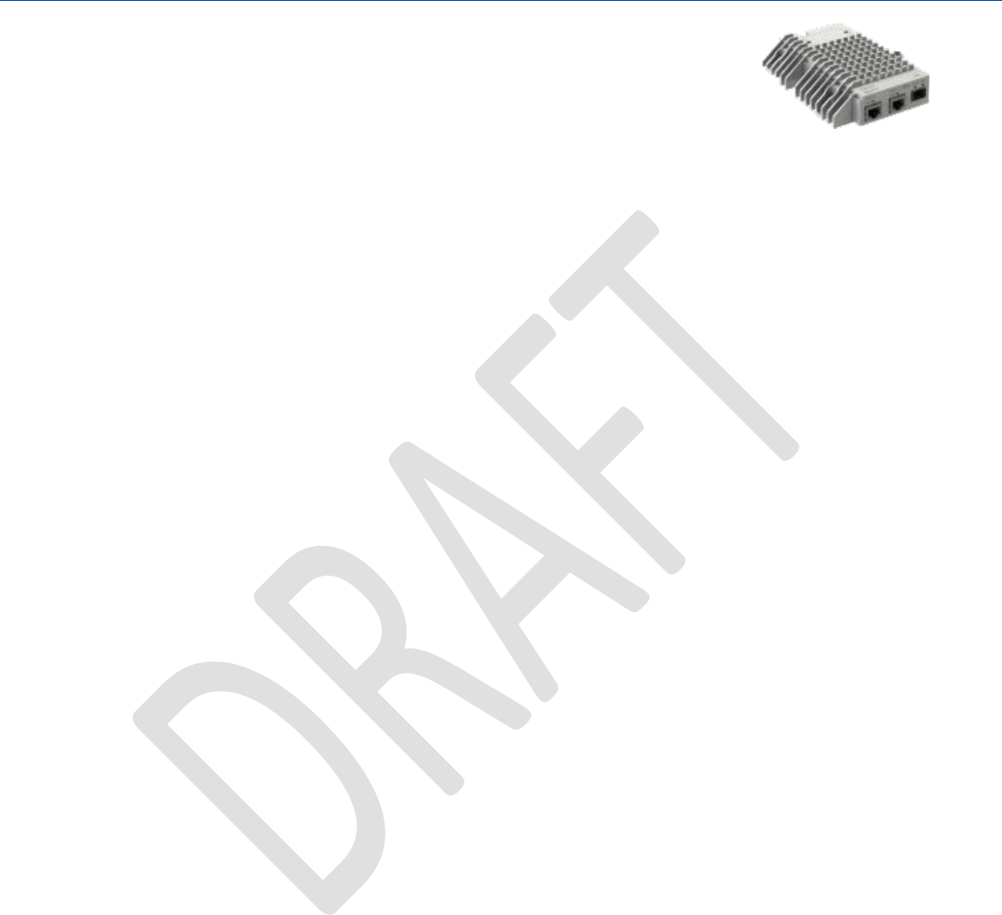
Corning Optical Communications User Manual I CMA-482-AEN I Page 74
Gigabit Ethernet Module (GEM)
GEM –Ethernet over fiber-to-copper.
10/100/1000BASE-T Ethernet 1000BASE-X fiber.
Two 802.3 at compliant Power over Ethernet (PoE) PSE ports
Interfaces
GEM – L2 switch contains:
One 1000BASE-X fiber SFP
Two 10/100/1000BASE-T with 802.3at compliant Power over
Ethernet (PoE+) PSE ports
Throughput
Six Gbps forwarding rate
Power
Installations with RAU5/RAU5x - powered via RAU secondary
power input (see RAU5 power consumption specifications)
Switching
IPv4 and IPv6 transparent
MAC table 512 entries
VLAN - unfiltered forwarding between ports
IGMP forward to all ports, no snooping
Physical
Characteristics
Mounting: Plug-in: RAU5/RAU5x upgrade module
Dimensions
(H x W x D):
1.28 x 3.79 x 5.95 in
(32.7 x 96.3 x 151.3 mm)
Weight: 1.1 lbs (0.5 kg)
Corning Optical Communications User Manual I CMA-482-AEN I Page 75
8 Appendix D: Ordering Information
RAU5x Remotes
Part Number
Description
RAU5XUS Remote access unit, five band remote supporting: ESMR 800/CELL 850, LTE 700,
AWS+AWS3 1700 and PCS 1900
RAU5XUS-A Remote access unit, supporting five bands and broad-band antenna.
ESMR 800/CELL 850, LTE 700, AWS+AWS3 1700, and PCS 1900; With antenna
assembled (P/N: RAU5US-ANT)
RAU5XUS-E Remote access unit, supporting five bands and 2x PoE+ ports.
ESMR 800/CELL 850, LTE 700, AWS+AWS3 1700, and PCS 1900
RAU5xUS-AE Remote access unit, supporting five bands, broad-band antenna and 2x PoE+
ports. ESMR 800/CELL 850, LTE 700, AWS+AWS3 1700, and PCS 1900
Antenna assembled (P/N: RAU5US-ANT)
RAU5XUS-2325 Remote access unit supporting seven bands: LTE 700, ESMR 800/CELL 850, PCS
1900, AWS and AWS3 1700, WCS 2300 and 2500 TDD
RAU5XUS-A2325 Remote access unit supporting seven bands: LTE 700, ESMR 800/CELL 850,
PCS 1900, AWS and AWS3 1700, WCS 2300, and 2500 TDD; includes assembled
antenna (P/N: RAU5US-ANT)
RAU5XUS-E2325 Remote access unit with two PoE+ ports supporting seven bands: LTE 700, ESMR
800/CELL 850, PCS 1900, AWS and AWS3 1700, WCS 2300, and 2500 TDD.
RAU5XUS-AE2325 Remote access unit, with two PoE+ Ports supporting seven bands: LTE 700, ESMR
800/CELL 850, PCS 1900, AWS+AWS3 1700, WCS 2300 and 2500 TDD; includes
assembled antenna (P/N: RAU5US-ANT)
RAU5 Remotes
Part Number
Description
RAU5US Remote Access Unit, five band Remote supporting: ESMR 800/CELL 850, LTE 700,
AWS 1700 and PCS 1900
RAU5US-E Remote Access Unit, 2 PoE+ ports and five band Remote supporting: ESMR
800/CELL 850, LTE 700, AWS 1700 and PCS 1900
RAU5US-ME Remote Access Unit, 2 PoE+ ports, five band Remote and MIMO bands
supporting: ESMR 800/CELL 850, MIMO-LTE 700, MIMO-AWS 1700 and PCS
1900
RAU5US-M Remote Access Unit, 5 band Remote and MIMO bands supporting: ESMR
800/CELL 850, MIMO-LTE 700, MIMO-AWS 1700 and PCS 1900
RAU5US-A Remote Access Unit, five band Remote supporting: ESMR 800/CELL 850, LTE
700, AWS 1700, and PCS 1900 + Ant assembled with the RAU5 -
PN:RAU5US-ANT
RAU5US-AE Remote Access Unit, 2 PoE+ ports and five band Remote supporting: ESMR
800/CELL 850, LTE 700, AWS 1700, and PCS 1900 + Ant assembled to the RAU5
- PN:RAU5US-ANT
RAU5US-AM Remote Access Unit, five band Remote and MIMO bands supporting: ESMR
800/CELL 850, MIMO-LTE 700, MIMO-AWS 1700, and PCS 1900 + Ant assembled
to the RAU5 - PN:RAU5US-ANT
RAU5US-AME Remote Access Unit, 2 PoE+ ports, five band Remote and MIMO bands
supporting: ESMR 800/CELL 850, MIMO-LTE 700, MIMO-AWS 1700 and PCS
1900 + Ant assembled with the RAU5 - PN:RAU5US-ANT
Corning Optical Communications User Manual I CMA-482-AEN I Page 76
Accessories
Part Number
Description
RAU5US-ANT Broad-band antenna module for RAU5/RAU5x
BR-RAU5US-Wall Remote bracket for wall mount installation; supports up to two RAU5x units
back-to-back
BR-RAU5US-TOP RAU5/RAU5x bracket for floating ceilings tile, mid-mount installation
BR-RAU5US-CAP Cover plate for “Top ceiling” RAU5x bracket (BR-RAU5US-TOP) – for installations
including RAU5/RAU5x without Corning external antenna
Corning Optical Communications LLC • PO Box 489 • Hickory, NC 28603-0489 USA 800-743-2675 • FAX: 828-325-5060 • International: +1-828-901-5000
• www.corning.com/opcomm
Corning Optical Communications reserves the right to improve, enhance, and modify the features and specifications of Corning Optical Communications
products without prior notification. A complete listing of the trademarks of Corning Optical Communications is available at
www.corning.com/opcomm/trademarks. All other trademarks are the properties of their respective owners. Corning Optical Communications is ISO 9001
certified. © 2016 Corning Optical Communications. All rights reserved . CMA-482-AEN