Corning Optical Communication 2KIDENSMRTBC MA2000 IDEN-SMR RHU IN TSX CASE User Manual
Corning Optical Communication Wireless MA2000 IDEN-SMR RHU IN TSX CASE Users Manual
Users Manual

MobileAccess 2000 System
Installation and Configuration Guide
P/N: 709C001xxx
REV: A01
Date: January, 2012


Preface
MA2000 Installation and Configuration Guide III
P
Pr
re
ef
fa
ac
ce
e
© Copyright 2012, MobileAccess. All Rights Reserved.
MOBILEACCESS IS A REGISTERED TRADEMARK OF MOBILEACCESS. THIS DOCUMENT CONTAINS OTHER TRADEMARKS,
TRADE NAMES AND SERVICE MARKS OF MOBILEACCESS AND OTHER ORGANIZATIONS, ALL OF WHICH ARE THE
PROPERTY OF THEIR RESPECTIVE OWNERS.
THIS DOCUMENT CONTAINS CONFIDENTIAL AND PROPRIETARY INFORMATION OF MOBILEACCESS AND MAY NOT BE
COPIED, TRANSMITTED, STORED IN A RETRIEVAL SYSTEM OR REPRODUCED IN ANY FORMAT OR MEDIA, IN WHOLE OR IN
PART, WITHOUT THE PRIOR WRITTEN CONSENT OF MOBILEACCESS. INFORMATION CONTAINED IN THIS DOCUMENT
SUPERSEDES ANY PREVIOUS MANUALS, GUIDES, SPECIFICATIONS, DATA SHEETS OR OTHER INFORMATION THAT MAY
HAVE BEEN PROVIDED OR MADE AVAILABLE TO THE USER.
THIS DOCUMENT IS PROVIDED FOR INFORMATIONAL PURPOSES ONLY, AND MOBILEACCESS DOES NOT WARRANT OR
GUARANTEE THE ACCURACY, ADEQUACY, QUALITY, VALIDITY, COMPLETENESS OR SUITABILITY FOR ANY PURPOSE OF
THE INFORMATION CONTAINED IN THIS DOCUMENT. MOBILEACCESS RESERVES THE RIGHT TO MAKE UPDATES,
IMPROVEMENTS AND ENHANCEMENTS TO THIS DOCUMENT AND THE PRODUCTS TO WHICH IT RELATES AT ANY TIME
WITHOUT PRIOR NOTICE TO THE USER. MOBILEACCESS MAKES NO WARRANTIES, EXPRESS OR IMPLIED, INCLUDING,
WITHOUT LIMITATION, THOSE OF MERCHANTABILITY AND FITNESS FOR A PARTICULAR PURPOSE, WITH RESPECT TO THIS
DOCUMENT OR ANY INFORMATION CONTAINED HEREIN.
Policy for Warrantee and Repair
MOBILEACCESS TESTS AND INSPECTS ALL ITS PRODUCTS TO VERIFY THEIR QUALITY AND RELIABILITY. MOBILEACCESS
USES EVERY REASONABLE PRECAUTION TO ENSURE THAT EACH UNIT MEETS THEIR DECLARED SPECIFICATIONS BEFORE
SHIPMENT. CUSTOMERS SHOULD ADVISE THEIR INCOMING INSPECTION, ASSEMBLY, AND TEST PERSONNEL ABOUT THE
PRECAUTIONS REQUIRED IN HANDLING AND TESTING OUR PRODUCTS. MANY OF THESE PRECAUTIONS CAN BE FOUND IN
THIS MANUAL.
THE PRODUCTS ARE COVERED BY THE FOLLOWING WARRANTIES:
General Warranty
MOBILEACCESS WARRANTS TO THE ORIGINAL PURCHASER ALL STANDARD PRODUCTS SOLD BY MOBILEACCESS TO BE
FREE OF DEFECTS IN MATERIAL AND WORKMANSHIP FOR ONE (1) YEAR FROM DATE OF SHIPMENT FROM
MOBILEACCESS. DURING THE WARRANTY PERIOD, MOBILEACCESS WILL REPAIR OR REPLACE ANY PRODUCT THAT
MOBILEACCESS PROVES TO BE DEFECTIVE. THIS WARRANTY DOES NOT APPLY TO ANY PRODUCT THAT HAS BEEN
SUBJECT TO ALTERATION, ABUSE, IMPROPER INSTALLATION OR APPLICATION, ACCIDENT, ELECTRICAL OR
ENVIRONMENTAL OVER-STRESS, NEGLIGENCE IN USE, STORAGE, TRANSPORTATION OR HANDLING.
Specific Product Warranty Instructions
ALL MOBILEACCESS PRODUCTS ARE WARRANTED AGAINST DEFECTS IN WORKMANSHIP, MATERIALS AND
CONSTRUCTION, AND TO NO FURTHER EXTENT. ANY CLAIM FOR REPAIR OR REPLACEMENT OF UNITS FOUND TO BE
DEFECTIVE ON INCOMING INSPECTION BY A CUSTOMER MUST BE MADE WITHIN 30 DAYS OF RECEIPT OF SHIPMENT, OR
WITHIN 30 DAYS OF DISCOVERY OF A DEFECT WITHIN THE WARRANTY PERIOD.
THIS WARRANTY IS THE ONLY WARRANTY MADE BY MOBILEACCESS AND IS IN LIEU OF ALL OTHER WARRANTIES,
EXPRESSED OR IMPLIED. MOBILEACCESS SALES AGENTS OR REPRESENTATIVES ARE NOT AUTHORIZED TO MAKE
COMMITMENTS ON WARRANTY RETURNS.

Preface
MA2000 Installation and Configuration Guide IV
Returns
IN THE EVENT THAT IT IS NECESSARY TO RETURN ANY PRODUCT AGAINST ABOVE WARRANTY, THE FOLLOWING
PROCEDURE SHALL BE FOLLOWED:
1. RETURN AUTHORIZATION IS TO BE RECEIVED FROM MOBILEACCESS PRIOR TO RETURNING ANY UNIT. ADVISE
MOBILEACCESS OF THE MODEL, SERIAL NUMBER, AND DISCREPANCY. THE UNIT MAY THEN BE FORWARDED TO
MOBILEACCESS, TRANSPORTATION PREPAID. DEVICES RETURNED COLLECT OR WITHOUT AUTHORIZATION MAY NOT BE
ACCEPTED.
2. PRIOR TO REPAIR, MOBILEACCESS WILL ADVISE THE CUSTOMER OF OUR TEST RESULTS AND ANY CHARGES FOR
REPAIRING CUSTOMER-CAUSED PROBLEMS OR OUT-OF-WARRANTY CONDITIONS ETC.
3. REPAIRED PRODUCTS ARE WARRANTED FOR THE BALANCE OF THE ORIGINAL WARRANTY PERIOD, OR AT LEAST 90
DAYS FROM DATE OF SHIPMENT.
Limitations of Liabilities
MOBILEACCESS'S LIABILITY ON ANY CLAIM, OF ANY KIND, INCLUDING NEGLIGENCE FOR ANY LOSS OR DAMAGE ARISING
FROM, CONNECTED WITH, OR RESULTING FROM THE PURCHASE ORDER, CONTRACT, QUOTATION, OR FROM THE
PERFORMANCE OR BREACH THEREOF, OR FROM THE DESIGN, MANUFACTURE, SALE, DELIVERY, INSTALLATION,
INSPECTION, OPERATION OR USE OF ANY EQUIPMENT COVERED BY OR FURNISHED UNDER THIS CONTACT, SHALL IN NO
CASE EXCEED THE PURCHASE PRICE OF THE DEVICE WHICH GIVES RISE TO THE CLAIM.
EXCEPT AS EXPRESSLY PROVIDED HEREIN, MOBILEACCESS MAKES NO WARRANTY, EXPRESSED
OR IMPLIED, WITH RESPECT TO ANY GOODS, PARTS AND SERVICES PROVIDED IN CONNECTION
WITH THIS AGREEMENT INCLUDING, BUT NOT LIMITED TO, THE IMPLIED WARRANTIES OF
MERCHANTABILITY AND FITNESS FOR A PARTICULAR PURPOSE. MOBILEACCESS SHALL NOT BE
LIABLE FOR ANY OTHER DAMAGE INCLUDING, BUT NOT LIMITED TO, INDIRECT, SPECIAL OR
CONSEQUENTIAL DAMAGES ARISING OUT OF OR IN CONNECTION WITH FURNISHING OF GOODS,
PARTS AND SERVICE HEREUNDER, OR THE PERFORMANCE, USE OF, OR INABILITY TO USE THE
GOODS, PARTS AND SERVICE.
Reporting Defects
THE UNITS WERE INSPECTED BEFORE SHIPMENT AND FOUND TO BE FREE OF MECHANICAL AND ELECTRICAL DEFECTS.
EXAMINE THE UNITS FOR ANY DAMAGE THAT MAY HAVE BEEN CAUSED IN TRANSIT. IF DAMAGE IS DISCOVERED, FILE A
CLAIM WITH THE FREIGHT CARRIER IMMEDIATELY. NOTIFY MOBILEACCESS AS SOON AS POSSIBLE.
NOTE: KEEP ALL PACKING MATERIAL UNTIL YOU HAVE COMPLETED THE INSPECTIO
WARNING: TO COMPLY WITH FCC RF EXPOSURE COMPLIANCE REQUIREMENTS, ANTENNAS USED FOR THIS
PRODUCT MUST BE FIXED MOUNTED ON INDOOR PERMANENT STRUCTURES, PROVIDING A SEPARATION DISTANCE OF AT
LEAST 20 CM FROM ALL PERSONS DURING NORMAL OPERATION.
WARNING: ANTENNA GAIN SHOULD NOT EXCEED 10 dBi.
WARNING: EACH INDIVIDUAL ANTENNA USED FOR THIS TRANSMITTER MUST BE INSTALLED TO PROVIDE A MINIMUM
SEPARATION DISTANCE OF 20 CM OR MORE FROM ALL PERSONS AND MUST NOT BE CO-LOCATED WITH ANY OTHER
ANTENNA FOR MEETING RF EXPOSURE REQUIREMENTS.
WARNING: THE DESIGN OF THE ANTENNA INSTALLATION NEEDS TO BE IMPLEMENTED IN SUCH A WAY SO AS TO
ENSURE RF RADIATION SAFETY LEVELS AND NON-ENVIRONMENTAL POLLUTION DURING OPERATION.
ATTENTION:
COMPLIANCE WITH RF SAFETY REQUIREMENTS:
MOBILEACCESS PRODUCTS HAVE NO INHERENT SIGNIFICANT RF RADIATION.
THE RF LEVEL ON THE DOWN LINK IS VERY LOW AT THE DOWNLINK PORTS. THEREFORE, THERE IS NO DANGEROUS RF
RADIATION WHEN THE ANTENNA IS NOT CONNECTED.
Preface
MA2000 Installation and Configuration Guide V
Laser Safety
THE LASER APERTURES /OUTPUTS ARE THE GREEN SC/APC BULKHEAD ADAPTERS LOCATED ON THE FRONT PANEL OF
THE EQUIPMENT.
THE PRODUCT IS CLASS 1/HAZARD LEVEL 1
FIBER OPTIC PORTS OF THE MOBILEACCESS2000 SYSTEM EMIT INVISIBLE LASER RADIATION AT THE 1310/1550 nm
WAVELENGTH WINDOW.
EXTERNAL OPTICAL POWER IS LESS THAN 10 mW, INTERNAL OPTICAL POWER IS LESS THAN 500 mW.
TO AVOID EYE INJURY NEVER LOOK DIRECTLY INTO THE OPTICAL PORTS, PATCHCORDS OR OPTICAL CABLES. DO NOT
STARE INTO BEAM OR VIEW DIRECTLY WITH OPTICAL INSTRUMENTS. ALWAYS ASSUME THAT OPTICAL OUTPUTS ARE ON.
ONLY TECHNICIANS FAMILIAR WITH FIBER OPTIC SAFETY PRACTICES AND PROCEDURES SHOULD PERFORM OPTICAL
FIBER CONNECTIONS AND DISCONNECTIONS OF THE MOBILEACCESS2000 DEVICES AND THE ASSOCIATED CABLES.
MOBILEACCESS2000 COMPLIES WITH 21 CFR 1040.10 AND 1040.11 EXCEPT FOR DEVIATIONS PURSUANT TO LASER
NOTICE NO. 50 (2007).
MOBILEACCESS2000 EMPLOYS A CLASS 3B LASER AND THEREFORE THE FOLLOWING LABEL IS AFFIXED INSIDE THE
UNIT ADJACENT TO THE LASER:
THE PRODUCT ITSELF HAS BEEN TESTED AND CERTIFIED AS A CLASS 1 LASER PRODUCT TO IEC/EN 60825-1 (2007).
IT ALSO MEETS THE REQUIREMENTS FOR A HAZARD LEVEL 1 LASER PRODUCT TO IEC/EN 60825-2: 2004 TO THE
SAME DEGREE.
Care of Fiber Optic Connectors
DO NOT REMOVE THE PROTECTIVE COVERS ON THE FIBER OPTIC CONNECTORS UNTIL A CONNECTION IS READY TO BE
MADE. DO NOT LEAVE CONNECTORS UNCOVERED WHEN NOT CONNECTED.
THE TIP OF THE FIBER OPTIC CONNECTOR SHOULD NOT COME INTO CONTACT WITH ANY OBJECT OR DUST.
REFER TO THE CLEANING PROCEDURE FOR INFORMATION ON THE CLEANING OF THE FIBER TIP.
CAUTION – USE OF CONTROLS OR ADJUSTMENTS OR PERFORMANCE OF PROCEDURES OTHER THAN
THOSE SPECIFIED HEREIN MAY RESULT IN HAZARDOUS RADIATION EXPOSURE

Preface
MA2000 Installation and Configuration Guide VI
RF Safety
WARNING! To comply with FCC RF exposure compliance requirements, antennas used for this product
must be fixed mounted on indoor permanent structures, providing a separation distance of at least
20 cm from all persons during normal operation.
1. Each individual antenna used for this transmitter must be installed to provide a
minimum separation distance of 20 cm or more from all persons and must not be
co-located with any other antenna for meeting RF exposure requirements.
2. The design of the antenna installation needs to be implemented in such a way so as
to ensure RF radiation safety levels and non-environmental pollution during
operation.
Compliance with RF safety requirements:
• MobileAccess products have no inherent significant RF radiation.
• The RF level on the downlink is very low at the downlink ports. Therefore, there is no
dangerous RF radiation when the antenna is not connected.
Standards and Certification
MobileAccess products have met the approvals of the following certifying organizations:
Product Certifications
US FCC 47 CFR part 15B, 22, 24, 90
NOTE: This equipment has been tested and found to comply with the
limits for a Class B digital device, pursuant to Part 15 of the FCC Rules.
These limits are designed to provide reasonable protection against
harmful interference in a residential installation. This equipment
generates, uses and can radiate radio frequency energy and, if not
installed and used in accordance with the instructions, may cause harmful
interference to radio or television reception, which can be determined by
turning the equipment off and on, the user is encouraged to try to correct
the interference by one or more of the following measures:
- Reorient or relocate the receiving antenna.
- Increase the separation between the equipment and receiver.
-Connect the equipment into an outlet on a circuit different from that to
which the receiver is connected.
-Consult the dealer or an experienced radio/TV technician for help.
Warning!
Changes or modifications to this equipment not expressly approved by
Mobile Access could void the user’s authority to operate the equipment.

Preface
MA2000 Installation and Configuration Guide VII
NRTL Safety UL 60950-1
Europe EN 301502, EN 300609, EN 301489,
EU Safety EN 60950-1
Laser Safety IEC 60825-1, IEC 60825-2
TRA TRA type approval for UAE
Company Certification
ISO ISO 9001: 2000 and ISO 13485: 2003
About this Guide and Other Relevant Documentation
This user guide describes how to perform the physical installation of the MA2000 systems. The
installation procedures of other units (e.g. RIU, MA850/MA860, LTE) relevant to the system are
detailed in their user manuals (see
Additional Relevant Documentation
below).
Additional Relevant Documents
The following documents are required if the corresponding units are included in your system.
Document Name
MA850/MA860 Installation and Configuration Guide
MobileAccess2000 700/800 Public Safety RHU Quick Installation Sheet
MobileAccess1000 / MobileAccess2000 User Manual Addendum for 700 MHz
LTE Solution
RIU Installation and Configuration Guide
SC-450 Installation and Configuration Guide
NMS MA 410/430 Installation and Configuration Guide
MA1000 MA2000 Commissioning Guide
MA Software Version Update Tool
List of Acronyms
BDA Bi-Directional Amplifier
BTS Base Transceiver Station
BTSC Base Transceiver Station Conditioner
BU Base Unit

Preface
MA2000 Installation and Configuration Guide VIII
DL Downlink
RU Remote (Hub )Unit
RIU Radio Interface Unit
UL Uplink

Table of Contents
Preface ...................................................................................................................................... III
Policy for Warrantee and Repair ......................................................................................................... III
General Warranty....................................................................................................................... III
Specific Product Warranty Instructions ........................................................................................ III
Returns ..................................................................................................................................... IV
Limitations of Liabilities .............................................................................................................. IV
Reporting Defects ...................................................................................................................... IV
Laser Safety ...................................................................................................................................... V
Care of Fiber Optic Connectors .................................................................................................... V
RF Safety ......................................................................................................................................... VI
Compliance with RF safety requirements: .................................................................................... VI
Standards and Certification ................................................................................................................ VI
Product Certifications ................................................................................................................. VI
Company Certification ............................................................................................................... VII
About this Guide and Other Relevant Documentation ......................................................................... VII
List of Acronyms .............................................................................................................................. VII
Table of Contents.............................................................................................................................. IX
1 Introduction to the MA2000 System .................................................................................. 1
1.1 MobileAccess2000 System Architecture ......................................................................................... 3
1.1.1 Head-End Equipment .......................................................................................................... 3
1.1.2 Remote-End Equipment ...................................................................................................... 3
1.2 Application Examples ................................................................................................................... 5
2 MA2000 System Elements ................................................................................................. 8
2.1 Enclosure Types........................................................................................................................... 9
2.1.1 MA2000 Remote Cabinet ..................................................................................................... 9
2.1.2 MA2000-Lite ..................................................................................................................... 11
2.1.2.1 Enclosure Internal Elements .................................................................................. 12
2.1.2.2 Digital Card Unit ................................................................................................... 13
2.1.2.3 Filters and Combiners ........................................................................................... 13
2.1.3 MA2000 TSX ....................................................................... Error! Bookmark not defined.
2.1.4 MA2000 QSX ....................................................................... Error! Bookmark not defined.
2.2 MA2000 Remote Location Units .................................................................................................. 15
2.2.1 MA2000 RU ...................................................................................................................... 15
2.2.1.1 MA2000 RU Front Panel ........................................................................................ 16
2.2.1.2 MA2000 RU Rear Panel ......................................................................................... 17
2.2.2 MA1200 Add-on................................................................................................................ 18
2.2.2.1 MA1200 Front Panel ............................................................................................. 18

Preface
MA2000 Installation and Configuration Guide X
2.2.2.2 MA1200 Rear Panel .............................................................................................. 19
2.2.3 8 x 4 Combiner................................................................................................................. 19
2.2.3.1 MA 8x4 Combiner Front Panel ............................................................................... 20
2.2.3.2 MA 8x4 Rear Panel ............................................................................................... 20
2.3 MA Base Unit ............................................................................................................................. 21
2.3.1 Base Unit Models and OPTMs ............................................................................................ 21
2.3.2 BU Panels ........................................................................................................................ 21
2.3.2.1 MA BU Front Panel ............................................................................................... 21
2.3.2.2 BU Rear Panel ...................................................................................................... 22
3 Installation Guidelines ..................................................................................................... 23
3.1 Infrastructure Preparation .......................................................................................................... 23
3.2 Installation Requirements ........................................................................................................... 23
3.3 Coaxial Cable Connections .......................................................................................................... 23
3.3.1 General Cable Installation Procedures ................................................................................ 23
3.3.2 RF Rules .......................................................................................................................... 24
3.3.3 Coax Cable Lengths and Losses ......................................................................................... 24
3.4 Fiber Optic Rules ....................................................................................................................... 25
3.5 Power Consumption, Connections and Power Supplies ................................................................. 26
3.5.1 Power Safety Instructions ................................................................................................. 26
3.5.2 Power Consumption of Units ............................................................................................. 26
3.5.3 Circuit Breakers ................................................................................................................ 26
3.5.4 Types of Power Supplies ................................................................................................... 27
3.6 Installation Conventions ............................................................................................................. 27
4 System Installation .......................................................................................................... 29
4.1 Pre-installation Instructions ........................................................................................................ 29
4.1.1 Unpacking and Inspection ................................................................................................. 29
4.2 Communication Room Installation ............................................................................................... 29
4.2.1 Rack Installation General Instructions ................................................................................ 30
4.2.2 Rack Installation Safety Instructions .................................................................................. 31
4.2.3 BU Connections ................................................................................................................ 32
4.3 Remote Cabinet Installation ........................................................................................................ 33
4.3.1 MA2000 MRC Wall Mount Installation................................................................................. 33
4.3.2 MRC Grounding - Integrated PS Wall Mount Model ............................................................. 36
4.3.3 MRC 2000 Rack Mount Installation .................................................................................... 37
4.3.4 Fiber Optic Connections .................................................................................................... 39
4.3.5 Power Connections ........................................................................................................... 40
4.3.5.1 Integrated Power Supply model ............................................................................ 40
4.3.5.2 External Power Supplies Model .............................................................................. 40
4.3.6 Antenna Connections ........................................................................................................ 40
4.4 MA2000-Lite Installation and Connections ................................................................................... 41
4.4.1 Mounting MA2000-Lite ...................................................................................................... 43

Preface
MA2000 Installation and Configuration Guide XI
4.4.2 MA2000-Lite Connections .................................................................................................. 44
5 Upgrading and Configuration Examples ........................................................................ 45
5.1 Common USA Configurations ...................................................................................................... 46
5.1.1 iDEN/SMR with PCS Add-on .............................................................................................. 46
5.1.2 Cell/PCS ........................................................................................................................... 47
5.1.3 Cell/PCSH ........................................................................................................................ 48
5.1.3.1 Cell/PCSH and LTE 700 ......................................................................................... 48
5.2 AWS Add-On ............................................................................................................................. 49
5.3 Public Safety 700/800 ................................................................................................................ 49
5.4 Typical International Configurations ............................................................................................ 50
5.4.1 Typical Asian Configuration: Cell/DCS+ UMTS .................................................................... 50
5.4.2 Typical European & Middle East Configuration: EGSM/DCS + UMTS Configuration ................ 50
5.4.3 iDEN ................................................................................................................................ 50
5.5 MA2000-Lite Cell/DCS and GSM/DCS Config for Telstra ................................................................ 51
6 Appendix : System Specifications .................................................................................. 52
RF Parameters .................................................................................................................................. 52
System Specs ................................................................................................................................... 56
Specifications of Units ....................................................................................................................... 57
6.1.1 MA 2000 MRC Remote Hub ............................................................................................... 57
6.1.2 MA 2000 Lite .................................................................................................................... 57
6.1.3 MA 2000 Remote Unit ....................................................................................................... 57
6.1.4 MA 1200 Add-On Specifications ......................................................................................... 57
6.1.5 Base unit Specifications .................................................................................................... 58
Ordering Information ........................................................................................................................ 58
MA2000 Installation and Configuration Guide 1
1 I
In
nt
tr
ro
od
du
uc
ct
ti
io
on
n
t
to
o
t
th
he
e
M
MA
A2
20
00
00
0
S
Sy
ys
st
te
em
m
MobileAccess2000 series provides enterprise level indoor coverage, of a wide range of multi-
operator wireless services over a single broadband infrastructure. Front-end wireless RF services
are routed, over optic fibers, to MA2000 series hubs that are securely located in the
telecommunication closets at each remote location. These modular service aggregation platforms
precisely combine multiple wireless service signals for simultaneous distribution over a common
broadband infrastructure.
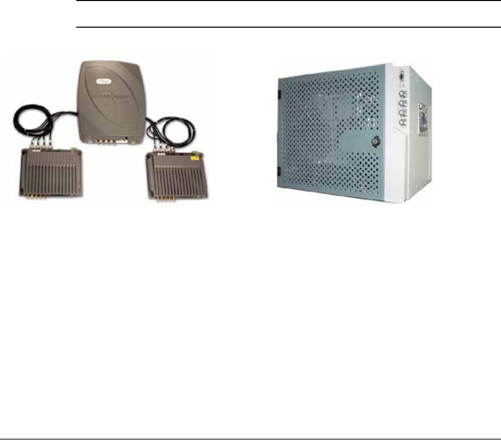
Two remote service hub models are available:
• MA2000-Lite – supports two remote units that are connected externally, where MA1200
Add-Ons and MA850/MA860 units can be integrated with the remote units.
MA2000 Cabinet (MRC) – internally houses a total of five remote units and MA1200 add-on
units with which MA850/MA860 can be integrated as an external assembly.
NOTE: MA2000 QSX unit is identical to the MA2000 TSX unit in addition to an Add-on service mounted
on top of the enclosure.
Figure 1-1. MA2000-Lite (left side) and MA2000 Cabinet (right side)
The supported units are:
• Remote Units (RUs) – Service specific modules that support up to two voice services and
perform the optic to RF conversion, filtering and amplification at the remote locations.
• MA1200 Add-On – Service specific module that provides support for an additional high
band voice service.
• MA850/MA860 – Module that supports data services
Features and Capabilities
• Multi-service platform that accommodates virtually any combination of wireless voice and
data services eliminating the need for separate overlay networks
• Scalable and future-safe – services can be added and removed without affecting existing
operators or end-users
MA2000-Lite
MA2000 Cabinet
MA2000 TSX
MA2000 QSX

Introduction to the MA2000 System MobileAccess2000 TSX System Architecture
MA2000 Installation and Configuration Guide 2
• MA2000-Lite components can be migrated to MA2000 MRC for increased capacity
•
• All active components are located in the communication closet/room
• Carrier class operation – MA2000 advanced signal handling ensures optimal performance for
all services within a multi-operator deployment
• Local and remote end-to-end monitoring and control through interface to SC-450 controller
• Conditioning and monitoring of input RF signals at the head-end through interface to MA-RIU

Introduction to the MA2000 System MobileAccess2000 TSX System Architecture
MA2000 Installation and Configuration Guide 3
1.1 MobileAccess2000 TSX System
Architecture
The MobileAccess2000 TSX/QSX solution is comprised of the following elements. Third-party
equipment is sold separately (i.e. cabling, antennas).
1.1.1 Head-End Equipment
At the head-end MobileAccess elements provide interface to the wireless service provider’s
network, where the signals can be conditioned through an active interface and transported over
optic fiber to the remote end.
• Radio Interface Unit (RIU): The RIU conditions the RF Downlink (DL) signals from an
operator’s signal source (BTS: base-transceiver stations or BDA: bi-directional amplifiers)
located inside the building. The RIU then custom tunes incoming signals in order to ensure a
constant level of RF before signals are passed to/from the Base Unit (BU). RF Uplink (UL)
signals from subscribers’ phones are received from the BU and transported back to the
operator’s signal source (BTS or BDA) and to the operator’s macro network outdoors.
• Base Unit (BU): The BU converts RF Downlink (DL) signals received from the RIU into an
optical signal. This optical signal is then transported over single or multi-mode fiber optic
cabling (SMF/MMF) to/from the MobileAccess2000 TSX units, which are housed inside of
IDF/Telco/IT closets at the remote-end locations, for distribution throughout the facility.
Uplink (UL) signals from subscribers’ phones are received from the antennas and sent back
to the TSX units through the fiber connection to the head-end, where they are converted
back from RF optical to RF electrical before being passed on to the RIU.
• System Controller: The system controller enables centralized remote management and
control of all MobileAccess2000 elements.
1.1.2 Remote-End Equipment
• At the remote end, the optical signal is reconverted to RF, amplified, filtered and distributed
over the broadband antenna infrastructure.Service Combiner Unit (SCU): The Service
Combiner Unit is a passive module that combines and distributes the UL and DL signals from
all the M2000 TSX and/or MA2000 QSX to the broadband antenna.
• MA2000 TSX: The MA2000 TSX delivers coverage for three RF services over a common
fiber/coax antenna infrastructure. The output of multiple TSX units can be combined to
provide a full multi-service solution over a common fiber/coax antenna infrastructure. The
TSX comes pre-packaged with applicable filters and other required accessories to simplify
the ability to order, service, and install this solution.
• MA2000 QSX: The MA2000 QSX delivers coverage for four RF services (CELL, PCS, 700LTE
and AWS) over a common fiber/coax antenna infrastructure. The output of multiple QSX and
TSX units can be combined to provide a full multi-service solution over a common fiber/coax
antenna infrastructure. The QSX comes pre-packaged with applicable filters and other
required accessories to simplify the ability to order, service, and install this solution. The
sub-components of the QSX are equivalent to that of the TSX with an additional AO.
• MA2000 TSX/QSX Sub-components:
• Remote Hub Unit (RHU): The RHU is a services-specific module that performs RF
optical to RF electrical conversion on signals received from the BU. Signals are
automatically filtered and amplified for transport over broadband coax cable to a passive
Introduction to the MA2000 System MobileAccess2000 TSX System Architecture
MA2000 Installation and Configuration Guide 4
antenna. Uplink (UL) signals from the antennas are then converted to optical signals
before being transmitted back to the BU. Each pre-configured RHU supports up to two
services.
• Add-On Module (AO): The AO is a single service module coupled with an RHU to
deliver an additional, third service at a lower incremental cost. The AO receives RF signal
from the RHU and amplifies it for transport across the broadband coax.
For end-to-end control, controllers installed at the head-end provide direct interface to the MA
elements and through them, control over the remote end elements.
Introduction to the MA2000 System MobileAccess2000 TSX System Architecture
MA2000 Installation and Configuration Guide 5
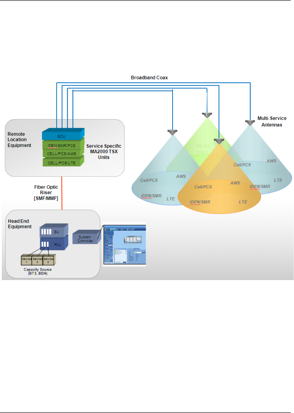
Figure 1-2. System Architecture
Figure 13 shows a basic block diagram of the system operation. On the downlink, services from
the BTS/BDA are transferred via interface to the Base Units (BUs). The interface, which may be
passive (i.e. Interface Box) or active (RIU), is used to attenuate the RF signals to the required
levels, converge them and distribute them to the BUs.
The BUs are wideband – they are not
service specific.
At the BUs, the RF signals are converted to optical signals and transmitted over the optic fiber to
(service-specific) RUs at the remote locations. At the remote locations, the RUs supported by the
hub (MRC or Lite) reconvert the optical signal to RF. The hub elements converge the voice
services together with 802.11 a/b/g data services (if MA850/MA860 units are installed) and
distribute them over the coax antenna infrastructure. The MA SC-450 (in installations with
remote management) provides monitoring and control of all active system elements.Application
Examples
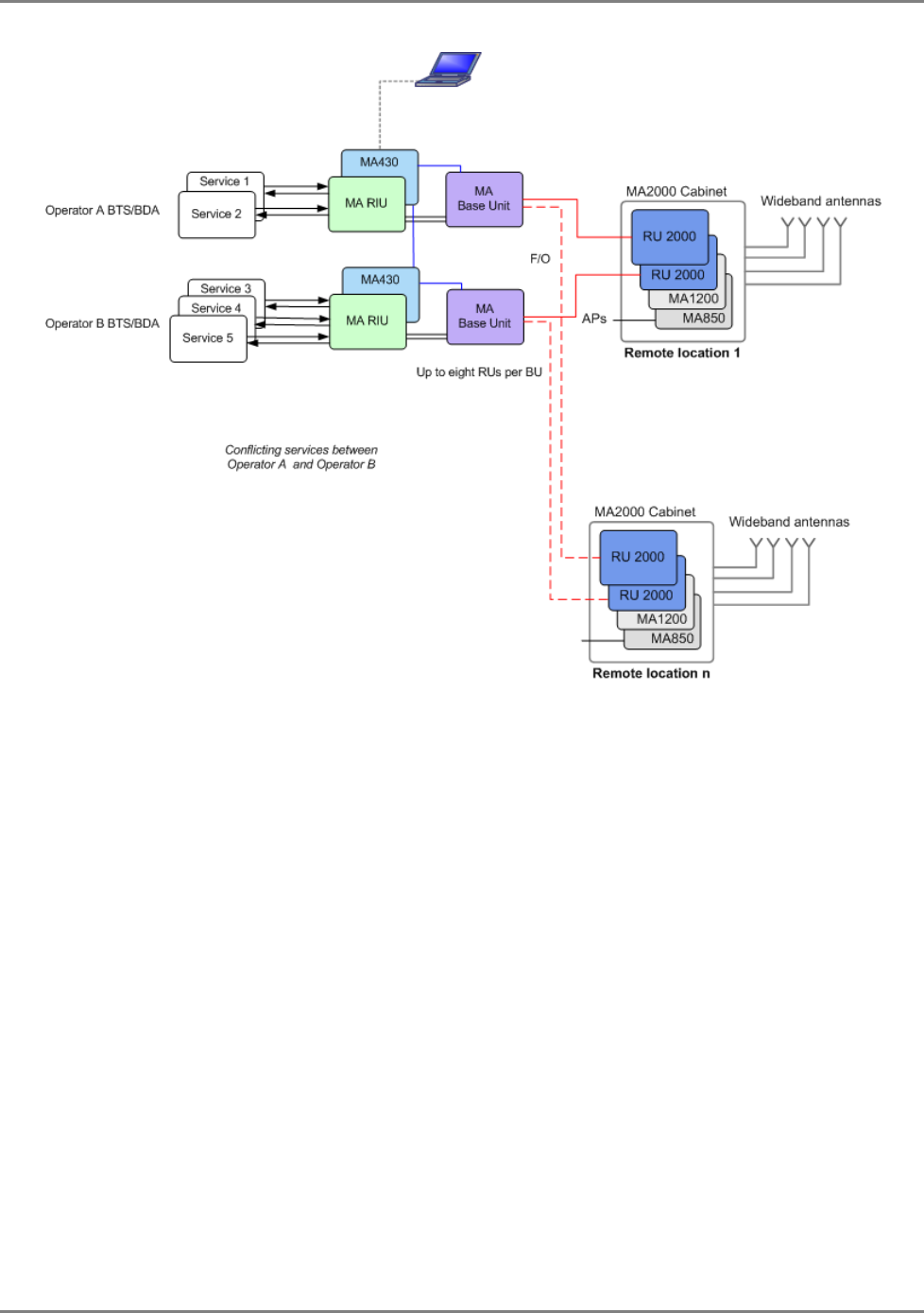
Figure 14 shows an example of an MA2000 Cabinet based solution. Five services from two
different operators are distributed, where services from Operator A conflict with those from
Operator B.
The converted optical signal is routed from the BUs directly to the corresponding RUs in each
Cabinet over optic fiber. Each BU supports connections to 8 RUs. Additional BUs are required for
connection to more RUs.
Services 1 and 2 are distributed through one of the RUs supported in each Cabinet. Services 3, 4
and 5 are distributed through the second RU and the MA1200 unit connected to that RU.
MA850 and MA860 converge 802.11a/b/g data services with the voice services to be distributed
through a common infrastructure of coax and wideband antennas.
*No. of supported services depends on
module: MA2000 Cabinet or MA2000-Lite
Introduction to the MA2000 System MobileAccess2000 TSX System Architecture
MA2000 Installation and Configuration Guide 6
Figure 1-3. Example of MA2000 Cabinet Architecture
Introduction to the MA2000 System MobileAccess2000 TSX System Architecture
MA2000 Installation and Configuration Guide 7
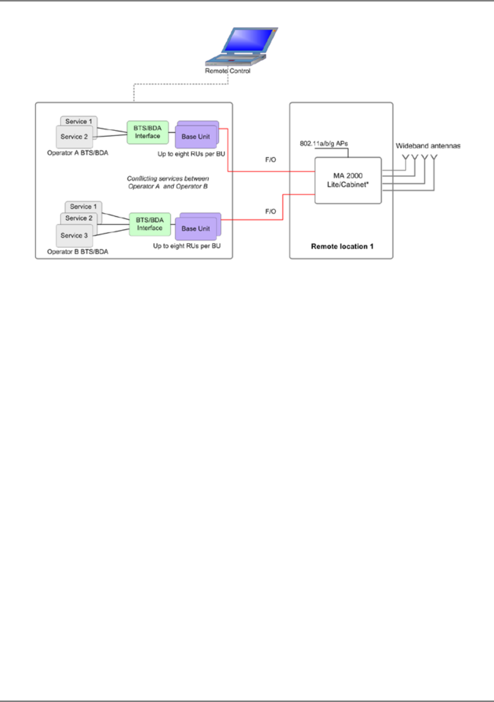
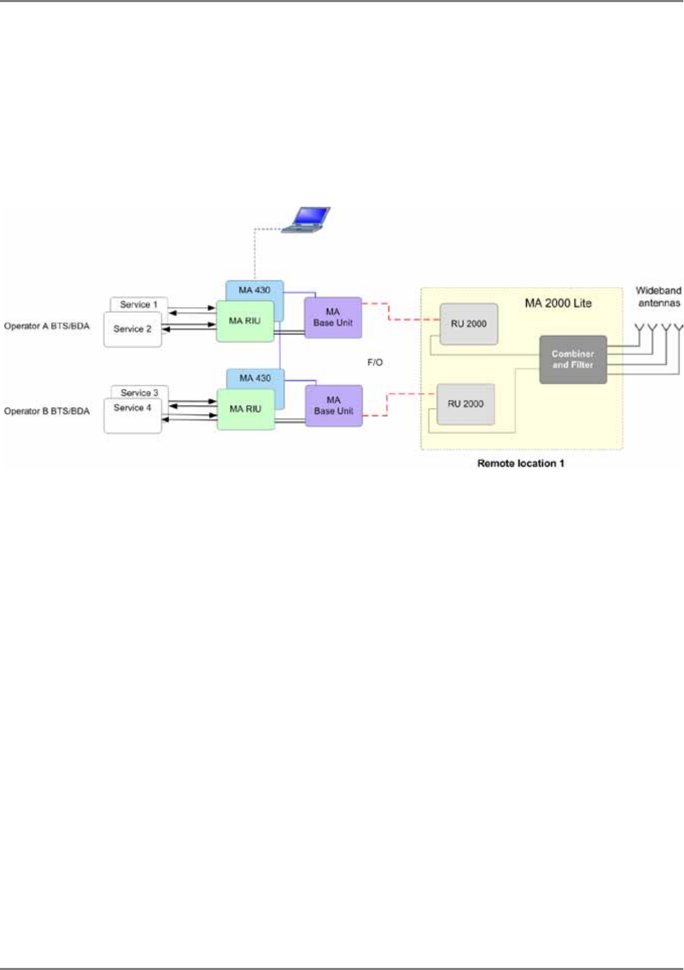
Figure 15 shows an example of an MA2000-Lite based solution. Four services from two different
operators are distributed.
The converted optical signal is routed from the BUs directly to the corresponding RUs over optic
fiber.
Services 1 and 2 are distributed through one of the RUs supported by MA2000-Lite. Services 3
and 4 are distributed through the second RU. The combiner and filter provides interface to the
antennas.
Figure 1-4.Example of MA2000-Lite Architecture

MA2000 Installation and Configuration Guide 8
2 M
MA
A2
20
00
00
0
S
Sy
ys
st
te
em
m
E
El
le
em
me
en
nt
ts
s
This chapter provides a full, detailed description of each of the system elements and their
individual connections. The element descriptions are organized according to the following
sections:
• Enclosures typesLite
• Remote Location Elements:
• MA2000 Remote Units (RUs)
• MA1200 Add-on
• Base Unit
NOTE: The following elements are fully described in their corresponding user guides: MA RIU, MA 850
/MA860, SC-450 Controller, MCT/NMS Management Application (described in MA410/MA430
Installation and Configuration Guide).
MA2000 System Elements Enclosure Types
MA2000 Installation and Configuration Guide 9
2.1 Enclosure Types
This section describes both types of enclosures (Cabinet/Lite) and their external connections.
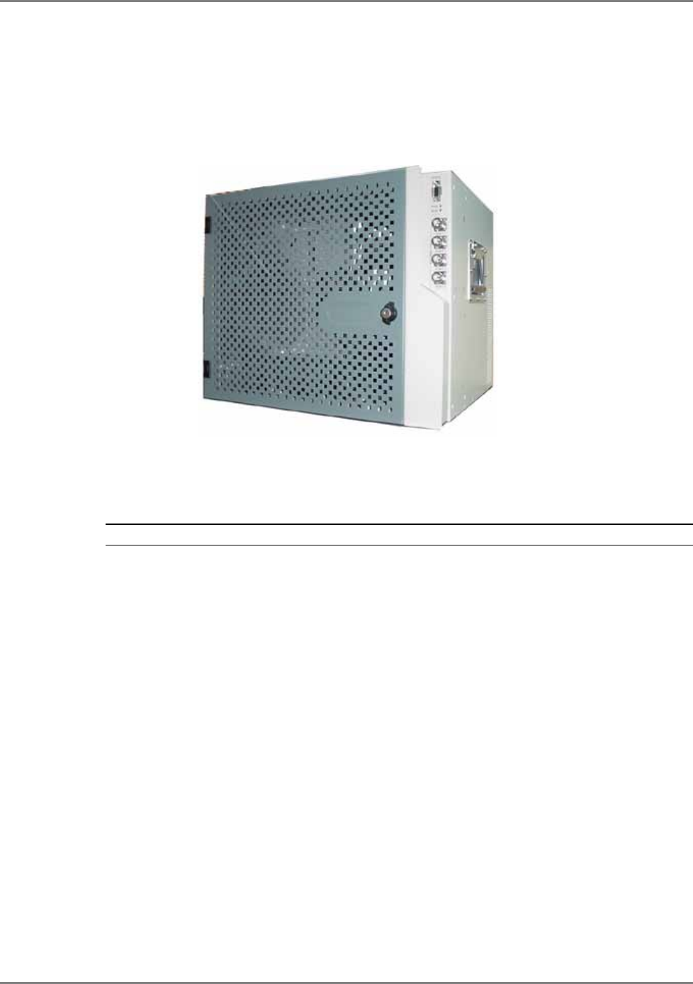
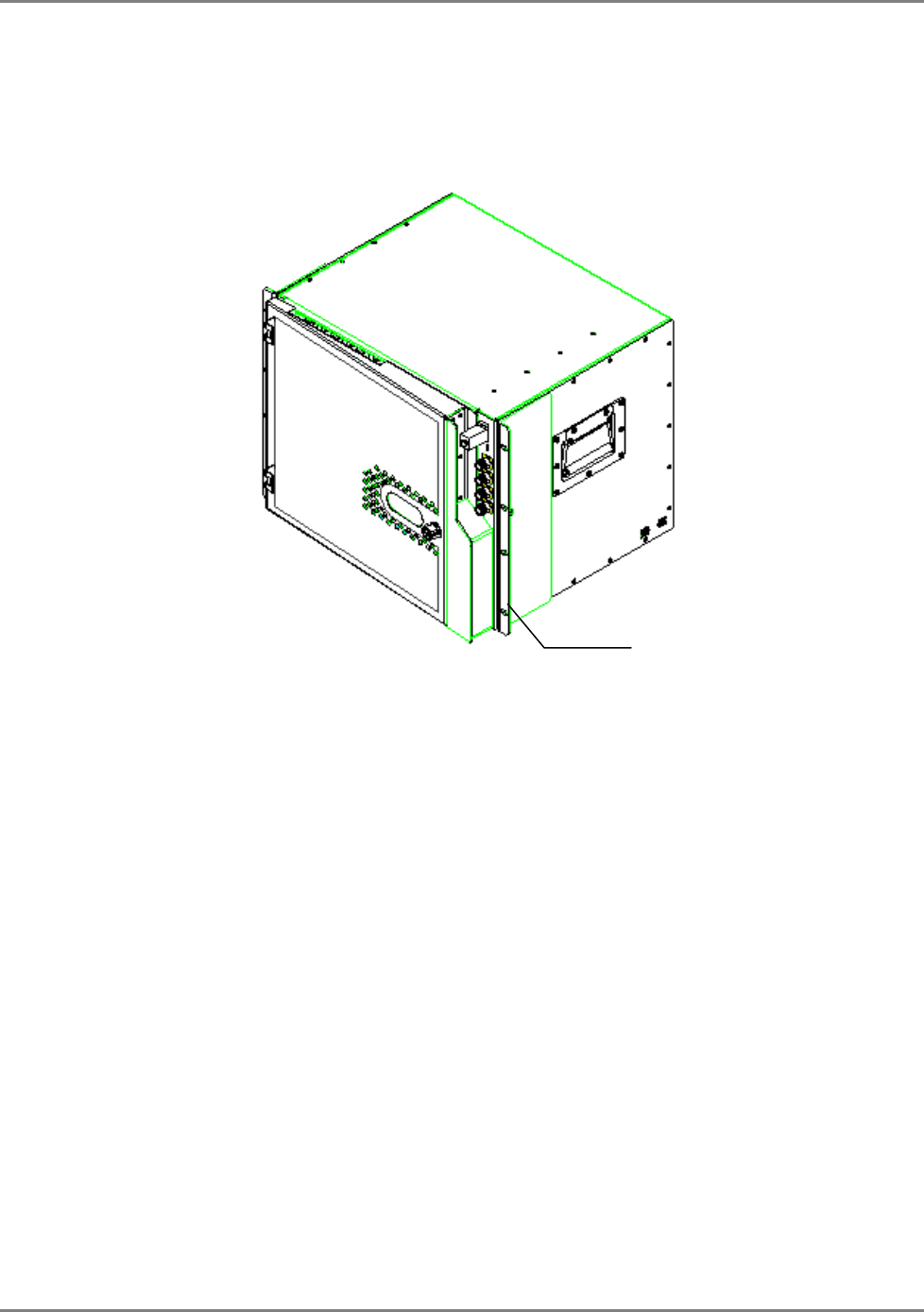
2.1.1 MA2000 Remote Cabinet
Figure 2-1. MA2000 MRC Closed Cabinet View
MA2000 Cabinet supports the following functions:
• Compactly houses up to five MA2000 RHU and MA1200 modules and the required filters
NOTE: The number of modules that can be housed depends on the models, required filtering, etc.
• MA850/MA860 can be connected externally
• Converges all voice services and provides a single interface to the antennas through external
connections
• Wall mounted or rack mounted
• Supplied in two models with differing power supply:
• Integrated power supply – fed from an external AC power source. The MA2000 RHU an
MA1200 Add-on modules are internally connected to the power supply. This model
includes a battery connection as well.
• External power supplies – power is routed to external connectors from which power is
routed internally to each MA2000 RHU and MA1200 Add-On module.
MA2000 System Elements Enclosure Types
MA2000 Installation and Configuration Guide 10
Open door views
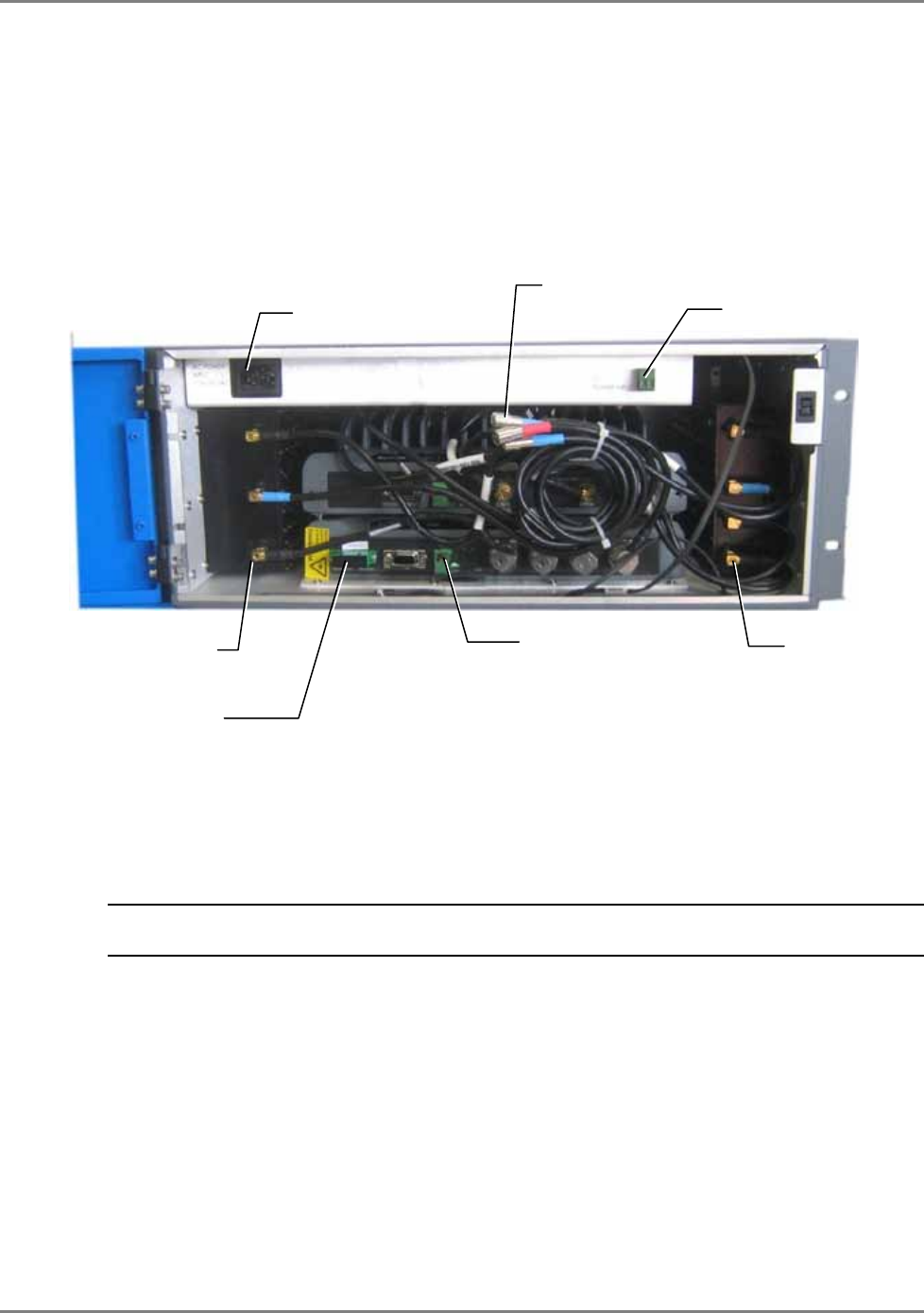
The following figure shows an open MA2000 MRC cabinet, integrated power supply model, with
four MA2000 RHU modules and four filters. (For clarity, the internal connections are
demonstrated separately in Figure 23).
Figure 2-2. MA2000 MRC Open Cabinet View (without internal connections)
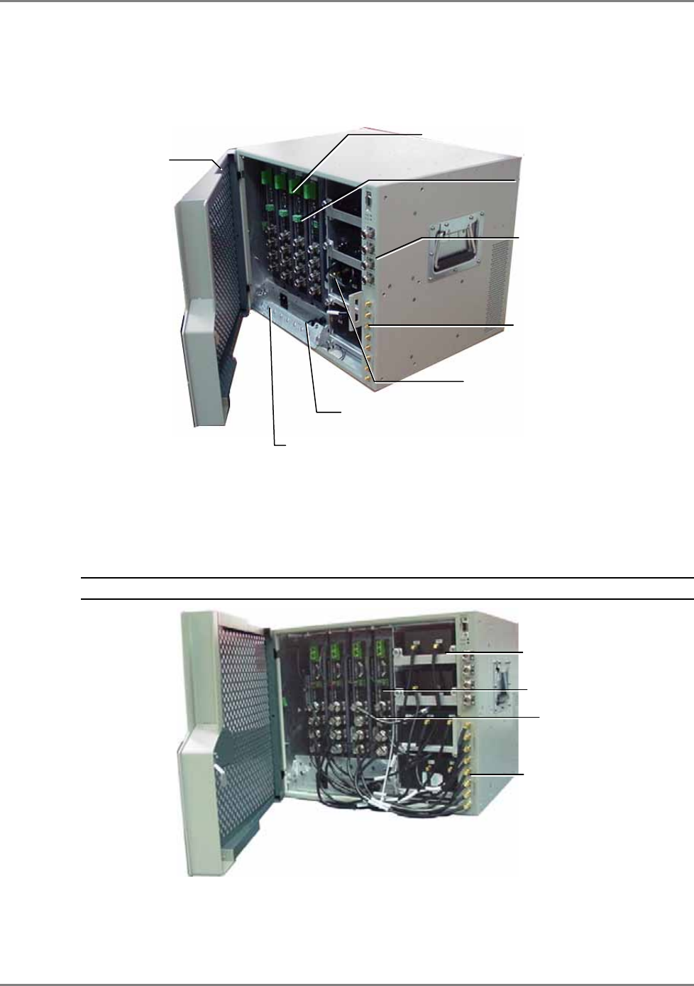
The following image shows the MA2000 MRC with the cabling. The antenna ports of the
individual modules are connected to the relevant filters and to the 8x4 Combiner. The PS
connections of each module are also connected to cables that are internally routed to the
integrated PS (a full detailed description of the connections is provided in chapter 5 ).
NOTE: The fiber optic connections are not displayed.
Figure 2-3. MA2000 MRC Open Cabinet with Internal Cabling
Optic fiber connection from
the corresponding BU
Slot for fitting
Optic Fibers
AC power input to
integrated power supply
Internal DC module
connections
Splitter/Combiner
connections
Filters (four in this
configuration example)
Connection to
external battery
Antenna ports (x4)
8x4 Combiner
Connections
Filter (x4)
Antenna ports (four in
each module)
PS connection
MA2000 System Elements Enclosure Types
MA2000 Installation and Configuration Guide 11
MA2000-Lite
The MA2000-Lite is designed to support up to 8 voice services, in addition to 802.11 data
services.
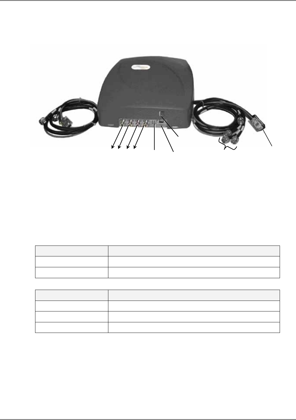
Figure 2-4. MA2000-Lite System
MA2000-Lite capabilities:
• External connections to two MA2000 RHUs (to which MA1200 Add-on units can be added)
• Internal filters and combiner (converges all services)
• Connection to MA850/MA860 for support of 802.11a/b/g data services
• External power supplies
The MA2000 enclosure contains two sets of cables, each providing connections to two MA2000
RUs.
Cable Connector Description
Four N-type connectors Coax connections to corresponding antennas
1x DB-9 connector Connection to RU front panel RS232 connector
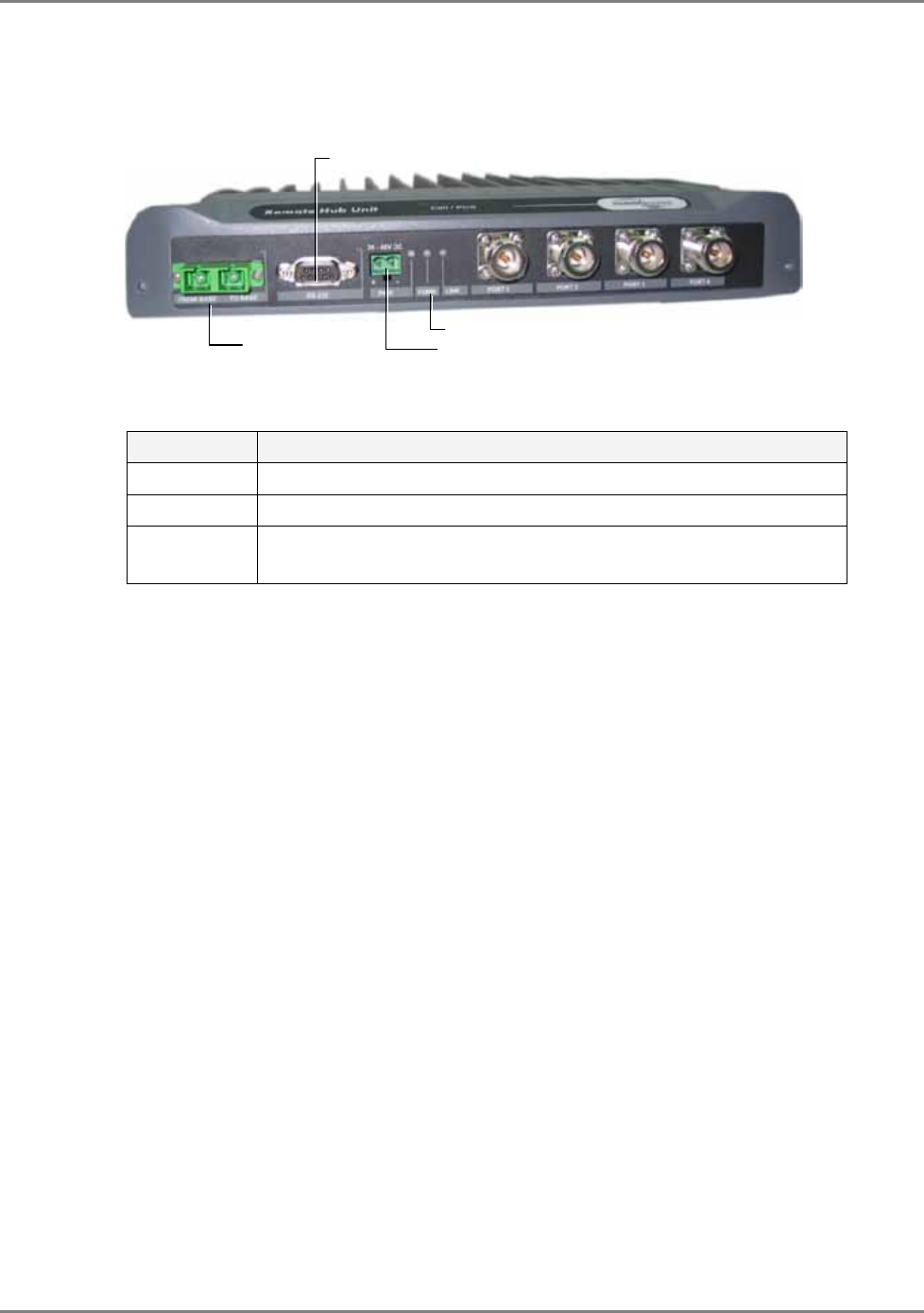
The following table describes the MA2000-Lite front panel connectors.
Connector Description
Ant-1 to Ant-4 (N-type) Coax connections to corresponding antennas
Control Control connector for MA service personnel.
Power 20 to 48V DC power input
MA2000-Lite
To RU 2000 front panel
antenna connections
Antenna connections
Connections to RU
2000 front panel
LEDs Control
PWR
To RU 2000 front
panel RS232
connector
MA2000 System Elements Enclosure Types
MA2000 Installation and Configuration Guide 12
The following table describes the front panel LEDs.
LEDs Description
Run Module is operating properly.
Power Green – required power is supplied.
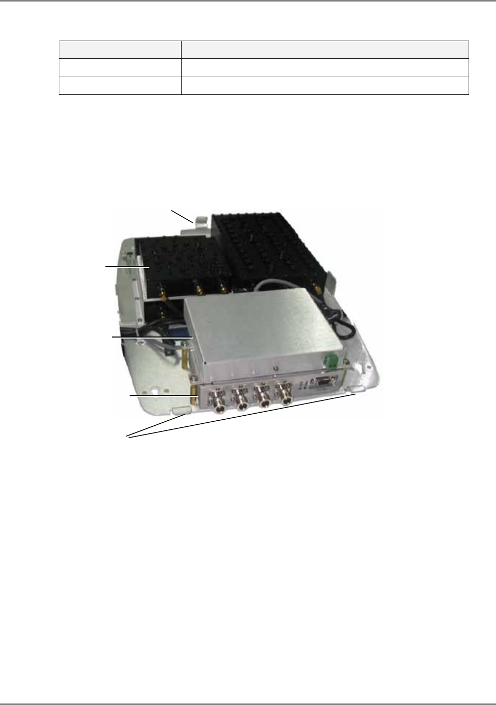
2.1.1.1 Enclosure Internal Elements
The MA2000-Lite enclosure includes:
• 8x4 Combiner (see section 2.2.3 for description)
• Digital Card unit (see 2.1.2.2).
• Filters and Combiners (see 2.1.2.3).
Figure 2-5. MA2000-Lite Internal Units
Digital module
Rear tab
8x4 Combiner
Filters and combiners
Front tabs
MA2000 System Elements Enclosure Types
MA2000 Installation and Configuration Guide 13
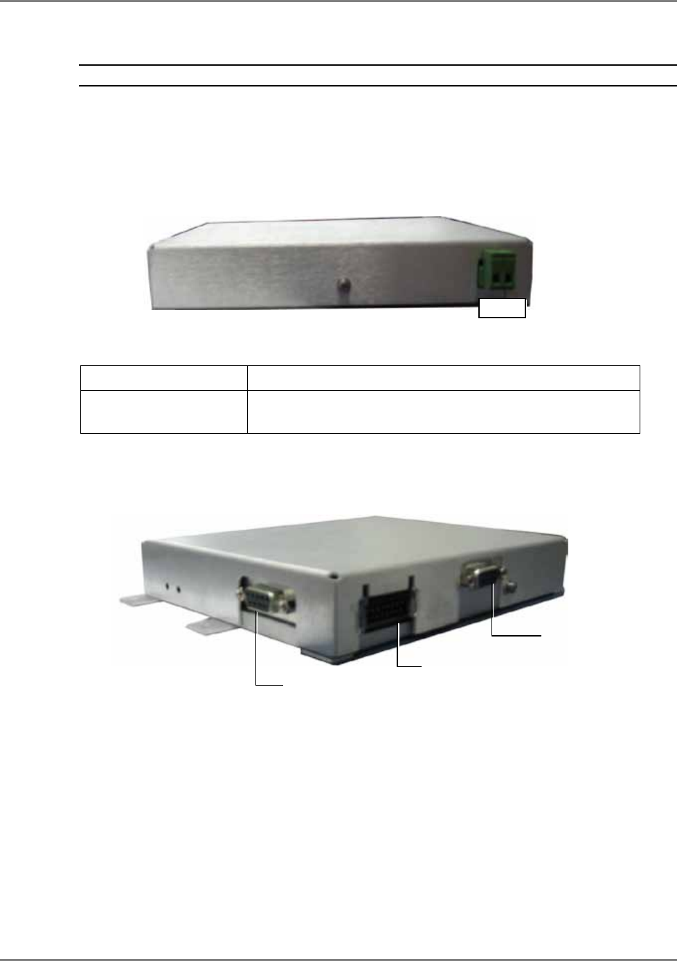
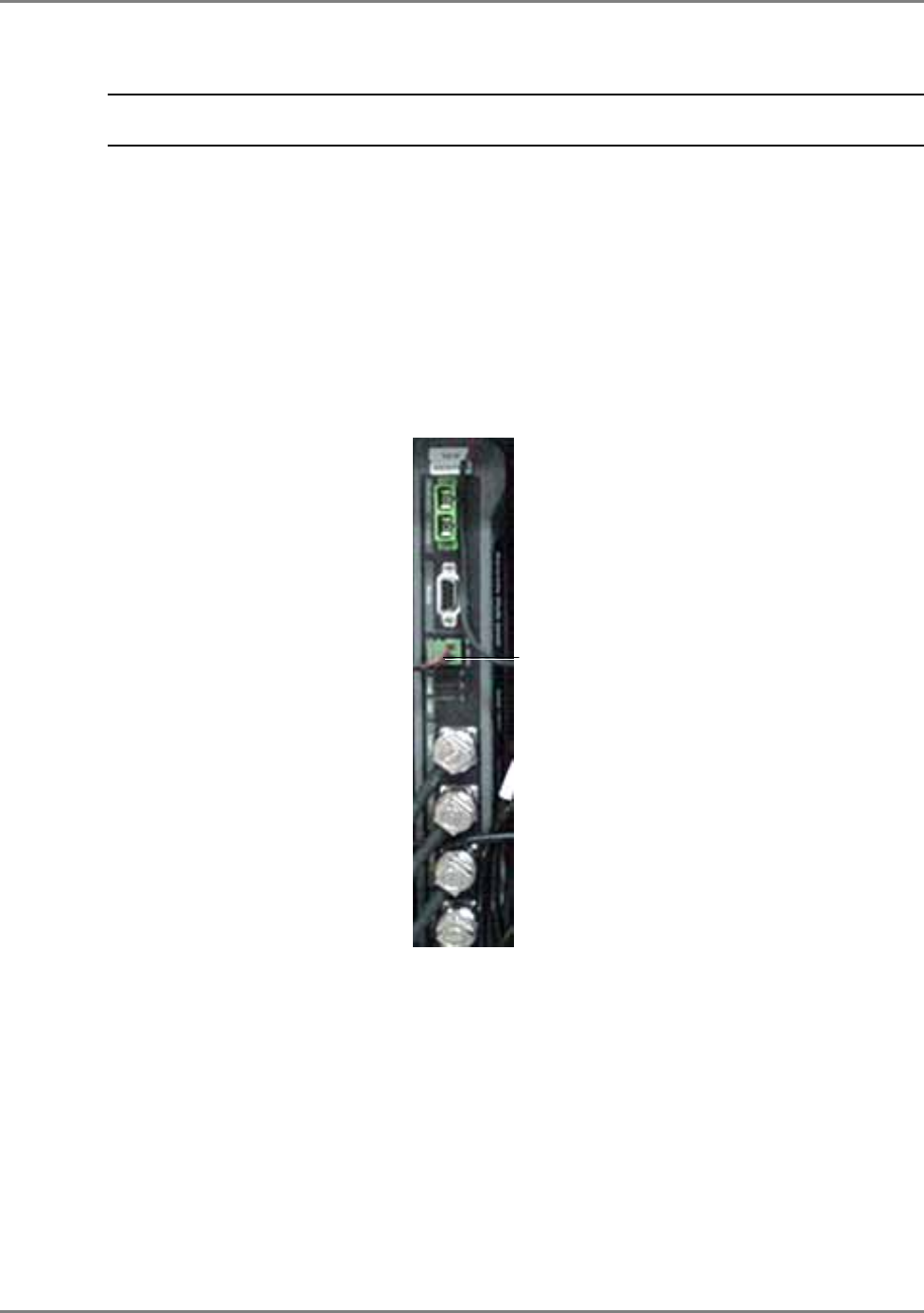
2.1.1.2 Digital Card Unit
NOTE: This unit is internal to the MA2000-Lite system.
The Digital unit enables antenna monitoring. It is connected to the 8x4 Combiner and to each of
Remote Units.
Digital Unit Front Panel
The front panel of the unit contains the power connector.
Figure 2-6. Digital Front Panel
The following table describes the front panel connectors.
Connector Description
PWR 20 to 48VDC. The PWR connector is external on the MA2000-
Lite enclosure front panel.
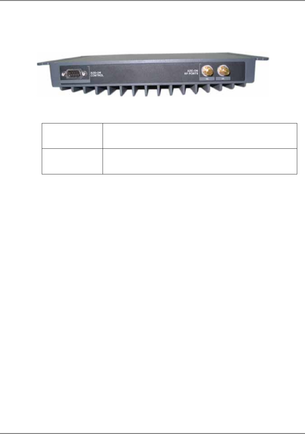
Digital Unit Rear Panel
The rear panel of the unit contains the control connections to the 8x4 Unit and to the Remote
Units.
Figure 2-7. Digital Rear Panel
2.1.1.3 Filters and Combiners
The filters and combiners vary according to the type of Remote Units. The filter and combiner
connections are described in Chapter 5 Upgrading and Configuration Examples.
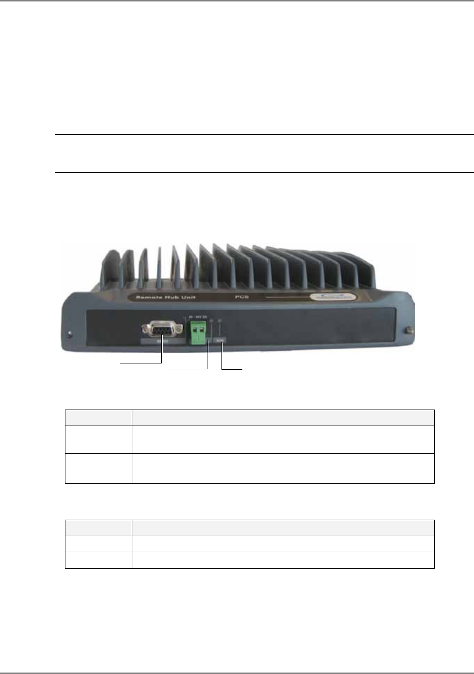
MA2000 TSX supports the following functions:
• Compactly houses up to two MA2000 RHU and MA1200 modules and the required filters
• Converges all voice services and provides a single interface to the antennas through external
connections
• Wall mounted or rack mounted
To the 8x4 Unit
Control connector
PWR
To RU Control
connector
To RU Control
connector
MA2000 System Elements Enclosure Types
MA2000 Installation and Configuration Guide 14
• Integrated power supply – fed from an external AC power source. The MA2000 RHU an
MA1200 Add-on modules are internally connected to the power supply. This model includes
a battery connection as well.
Open door view
The following figure shows an open TSX cabinet with one MA2000 RHU and one MA1200 module
and four filters. (For clarity, the internal connections are demonstrated separately in Figure 23).
Figure 2-8. MA2000 TSX Open Cabinet View
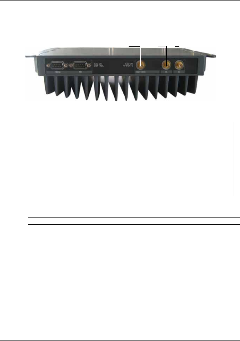
The antenna ports of the individual modules are connected to the relevant filters and to the 8x4
Combiner. The PS connections of each module are also connected to cables that are internally
routed to the integrated PS (a full detailed description of the connections is provided in chapter
5).
NOTE: The fiber optic connections are not displayed. Also, the antenna connections are performed through
the SCU-4 which is mounted on top of the cabinet (not shown here).
AC power input to
integrated power supply
Internal DC module
connections Filter
Filter
Optic fiber connection from
the corresponding BU
DC power input to
integrated power supply
Low band/High
band connections

MA2000 System Elements MA2000 Remote Location Units
MA2000 Installation and Configuration Guide 15
2.1.2
2.2 MA2000 Remote Location Units
Service specific units located at each remote location convert the optical signals received from
the Base Units to RF signals and route them to the coax antenna infrastructure.
NOTE: The voice services are converged by an 8x4 Combiner unit that is installed in the Cabinet
enclosure and the Lite module.
The following types of service specific elements are available:
• Remote Units (RUs) – support two voice services
• MA1200 Add-On – adds an additional (third) voice service to the host RU to which it is
connected.
• MA850/MA860 – converges data services from 802.11a/b/g APs and distributes them over
the same coax and antenna infrastructure
NOTE: The MA850/MA860 is described in detail in the MA850/MA860 Configuration and Installation
guide.
2.2.1 MA2000 RU
MA2000 RU is a service specific module that is either housed in the MA2000 Cabinet or
connected externally to the MA2000-Lite module.
It provides the following functions:
• Performs the optic to RF (and vice versa) conversion at the remote locations
• Supports two services – high-band and low-band
• Interfaces to the optic fiber from the BU
• Add-On ready – MA1200 can be added to support an additional services
• Remote management - requires connection of host BU connection to an SC-450 controller
Note: MA2000 also supports management via MA410/MA430 controllers.
MA2000 System Elements MA2000 Remote Location Units
MA2000 Installation and Configuration Guide 16
2.2.1.1 MA2000 RU Front Panel
The MA2000 RU front panel contains the fiber optic connections to the BU, four coax
connections to the antennas, power connections and status indicators.
Figure 2-9. MA2000 RU Front Panel
Table 2-1. RU 2000 Front Panel Indicators
LED Description
COMM Active communication detected
LINK Optical link to BU detected
PWR DC power connection.
20 to 48VDC
Fiber optic BU
connections
Power connector
LEDs
MA service
connecto
RF ports 1 to 4
MA2000 System Elements MA2000 Remote Location Units
MA2000 Installation and Configuration Guide 17
2.2.1.2 MA2000 RU Rear Panel
The MA2000 RU rear panel provides the control, RF interface and optic interface ports that
enable connecting to an MA1200 Add-On unit.
Figure 2-10. MA2000 RU Rear
Table 2-2. MA2000 RU Rear Panel Connectors
Add-on control Transmits the control signals from MA1200 Add-On module to the
MA2000 RU module. The Add-on Control port is connected to the
MA1200 Add-On From port.
DL, UL Transmit the RF signals to- and from- the MA1200 Add-On module.
These ports are connected to the corresponding ports on the
MA1200 rear panel: DL to DL, UL to UL.
2.2.2
MA2000 System Elements MA2000 Remote Location Units
MA2000 Installation and Configuration Guide 18
2.2.3 MA1200 Add-on
The MobileAccess1200 Add-On module is used to provide support for an additional service to an
MA 2000 RU. The host MA2000 RU and the MA1200 Add-On are interconnected and either
housed in a MA2000 Cabinet or connected externally to a MA2000-Lite ‘enclosure’.
MA1200 Add-On provides the following functions:
• Single service – either low-band or high-band
• Installed only as an addition to a MA2000 RU
NOTE: MA1200 add-on does NOT interface directly to the fiber optic infrastructure, does not perform the
optic to RF conversion and does not interface to the antennas. All these functions are provided by the host
MA2000 RU unit.
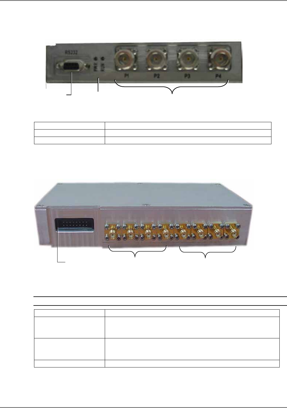
2.2.3.1 MA1200 Front Panel
The MA1200 front panel contains the power connection and status LEDs. (The RS-232 connector
is reserved for MA service personnel). The figure below shows the MA 1200 front view. It is
followed by a description of the connections and LEDs.
Figure 2-11. MA1200 Front Panel
Table 2-3. MA1200 Front Panel Connectors
LED Description
RS232 Servicing connector to be used by MA service personnel for
maintenance.
PWR DC Power connection.
25 to 48VDC
Table 2-4. MA1200 Front Panel Indicators
LED Description
RUN When blinking, indicates that the RU is in normal operating mode.
PWR Power ON
Maintenance
RUN
PWR
MA2000 System Elements MA2000 Remote Location Units
MA2000 Installation and Configuration Guide 19
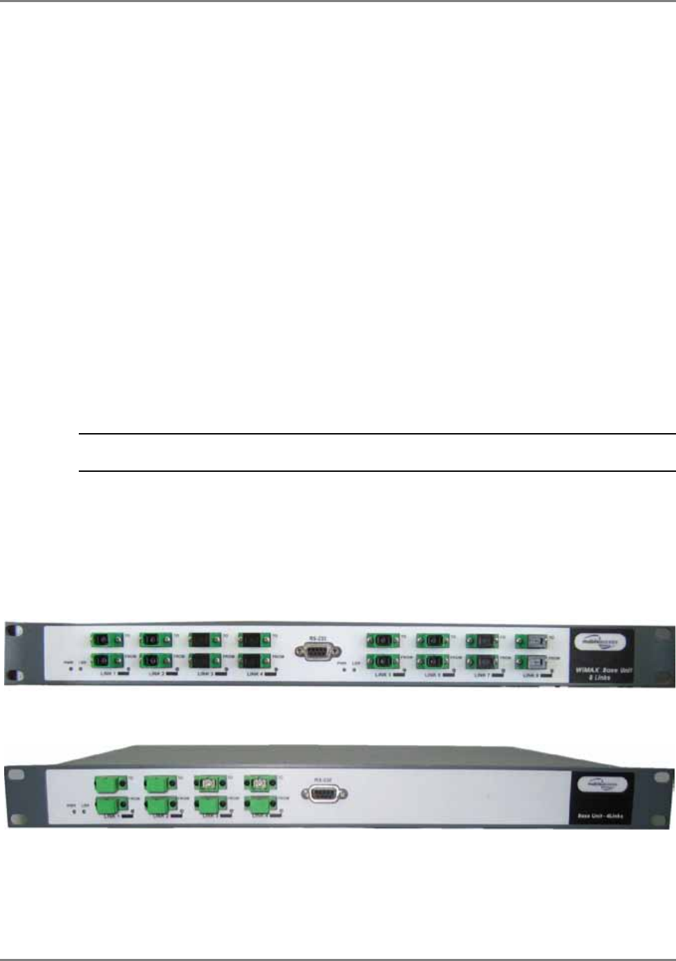
2.2.3.2 MA1200 Rear Panel
The MA1200 rear panel contains the control connectors and the RF connections to the MA2000
RU and MA850/MA860.
Figure 2-12. MA1200 Rear Panel
Table 2-5. MA1200 Rear Panel Connectors
Add-on Control Transmits the control signals between the MA1200 module and the
MA850/MA860 and MA2000 RU modules.
From – receives control signals from the MA2000 RU. Connected to
the MA2000 RU Add-on Control connector.
To – feeds control signals to MA850/MA860 (in configurations that
include MA850/MA860)
DL, UL Transmit the RF signals to- and from- the MA1200 add-on module.
These ports are connected to the corresponding ports on the MA
2000 rear panel: DL to DL, UL to UL.
High Service RF output port. Connected to combiner/splitter to be
combined with other services supported by the MA2000 system.
2.2.4 8 x 4 Combiner
NOTE: This unit is internal to the MA2000 system – both Cabinet and Lite models.
This unit is installed in the MA2000 system Cabinet and MA2000-Lite enclosures. It combines the
RF outputs of the RUs in the corresponding system and provides a common interface to the coax
antenna infrastructure.
The 8x4 Combiner provides the following capabilities:
• Supports up to eight RF voice service connections: four high-band and four low-band
• Supports four antenna interface ports (located externally on the MA2000-Lite)
• Provides low RF loss and high isolation for the input devices
High Band
DL
UL
MA2000 System Elements MA2000 Remote Location Units
MA2000 Installation and Configuration Guide 20
2.2.4.1 MA 8x4 Combiner Front Panel
The front panel of the unit contains the four antenna interface ports, LEDs and control port.
Figure 2-13. 8x4 Combiner Front Panel
The following table describes the front panel connectors.
Connector
Description
Ant-1 to Ant-4 (N-type) Connections to corresponding antennas
Setup Future Option
2.2.4.2 MA 8x4 Rear Panel
The rear panel of the unit contains four low-band and four high-band ports as well as the control
port.
Figure 2-14. 8x4 Combiner Rear Panel
The following table describes the rear panel connectors.
NOTE: Connector on rear panel is for future option.
SMA Connectors
Description
Low Band Four connectors (ports 1-4) for the low-band outputs of the
corresponding remote unit. Refer to
Chapter
5
for the exact
connections relevant to each configuration.
High Band Four connectors (ports 5-8) for the
high-band
outputs of the
corresponding remote unit. Refer to
Chapter
5
for the exact
connections relevant to each configuration.
Control Interfaces to the Digital card (that enables antenna monitoring)
Fiber Optic connection
Setup
connection
Control Ports 1-4: Low Band connectors
Ports 5-8: High Band connectors
Antenna ports 1-4
LEDs
MA2000 System Elements MA Base Unit
MA2000 Installation and Configuration Guide 21
2.3 MA Base Unit
The BU (Base Unit) is a wideband device that performs the conversion between the BTS/BDA
(passive or active) interface RF signal and the remote units’ optic signal.
Base Unit capabilities
• Supports all services distributed by MobileAccess systems
• Fiber connection to up to 8 RUs
• Setup and monitoring through connection to the host SC-450 controller and NMS software
application
• Dry contact alarms
• Front panel indicators providing status on optical link internal circuitry and signal level
2.3.1 Base Unit Models and OPTMs
Two models of MA BUs are available:
• Four-port unit – supports optic connections to four RUs
• Eight-port unit – supports optic connections to eight RUs
Each 4-port unit is referred to as OPTM. An 8-port unit consists of two 4-port modules or,
referred to as OPTMs.
NOTE: Each 4-port module (OPTM) is separately accessed and managed in the MCT and NMS
management applications.
2.3.2 BU Panels
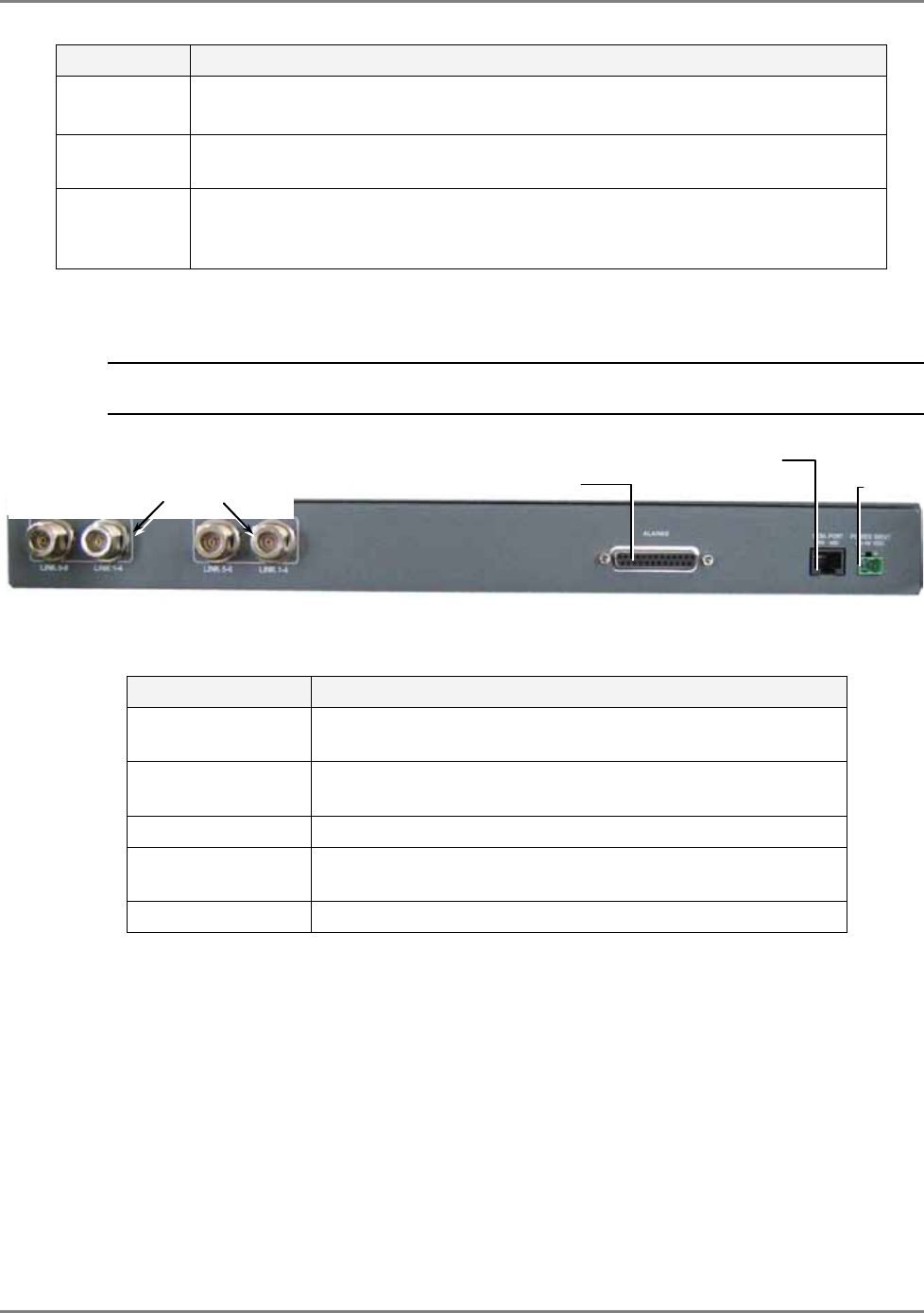
2.3.2.1 MA BU Front Panel
The front panel contains the optical connections and indicators. Each four-port element has a
dedicated set of indicators (PWR, LSR and Link 1 to Link 4 or Link 5 to Link 8).
Figure 2-15. Eight-Port MA BU Front Panel
Figure 2-16. Four-Port BU Front Panel
Table 2-6. MA BU Front Panel Indicators
Four ports and corresponding indicators
Four ports and corresponding indicators
MA2000 System Elements MA Base Unit
MA2000 Installation and Configuration Guide 22
LED Description
PWR Power input detected for the corresponding unit.
20 to 48VDC
LSR ON - laser circuitry for the corresponding element (group of four ports) is
functioning correctly.
Link 1-4, 5-8 ON - the optical link to/from the connected remote functions within the
specifications in both directions.
Blinking - optical power from remote is lower than required
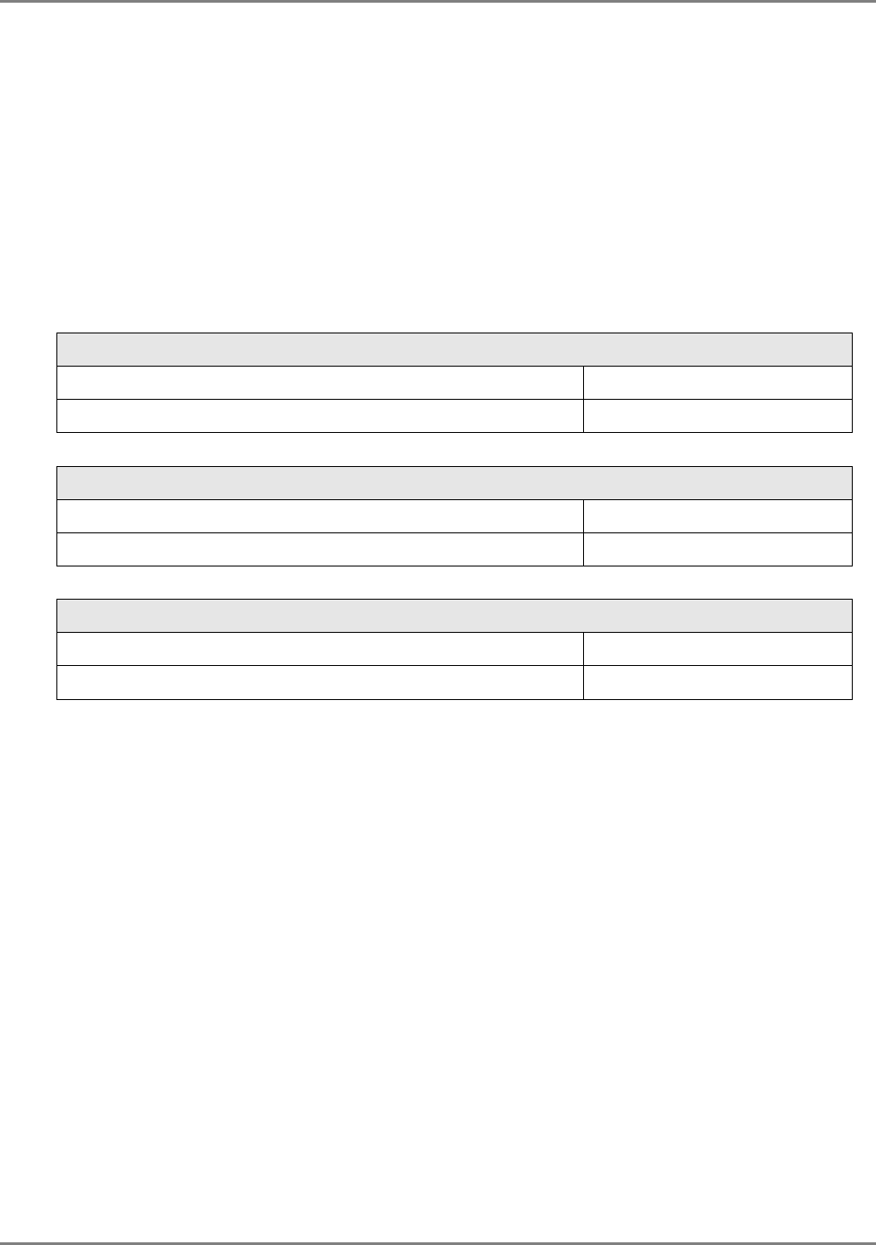
2.3.2.2 BU Rear Panel
The BU rear panel contains the RF connections, Alarms, NMS and power connections.
NOTE: The following figure shows the rear panel of an 8-port BU. A 4-port BU contains a single UL and a
single DL RF connector.
Figure 2-17. MA BU Rear Panel (RF Connections)
Table 2-7. MA BU Rear Panel Connections
Connector Description
Uplink output Uplink connectors to be connected on BTS/BDA side. For an
8-port BU, both UL connectors must be connected.
Downlink input Downlink connectors to be connected on the BTS/BDA side.
For an 8-port BU, both DL connectors must be connected.
Com Port RS485 Connection to SC-450 controller, rear panel RS485 port.
Alarms Dry-contact connections to BTS/BDA (normally closed).
Relevant only for system without SC-450 controller.
PWR Power connection: 20 to 48VDC
Pair of uplink and downlink RF
connections for interface to BTS
id
Alarms dry-contact
connector
MA 410/MA430
Power

MA2000 Installation and Configuration Guide 23
3 I
In
ns
st
ta
al
ll
la
at
ti
io
on
n
G
Gu
ui
id
de
el
li
in
ne
es
s
3.1 Infrastructure Preparation
This following installation rules are based on the assumption that site survey and installation
planning (
including power requirements
) have been completed.
3.2 Installation Requirements
The infrastructure preparation consists of two main phases:
A. Floor Planning: Planning the distribution of the antennas on each floor to provide the
required coverage.
B. Telecom Closet Planning: Planning the layout of the devices and cables in the telecom
closet or shaft. This includes the MA850/MA860, 802.11 Access Points, cabling and other
voice service distribution systems that are relevant to the specific installation.
3.3 Coaxial Cable Connections
3.3.1 General Cable Installation Procedures
Observe the general cable installation procedures that meet with the building codes in your area.
The building code requires that all cabling be installed above ceiling level (where applicable).
The length of cable from the risers to each antenna must be concealed above the ceiling.
The cable must be properly supported and maintained straight using tie-wraps, cable trays and
clamps or hangers every 10 feet (where practical above ceiling level). Where this is not practical,
the following should be observed:
• The minimum bending radius of the supplied ½” coax cable should be 7”.
• Cable that is kinked or has a bending radius smaller than 7” must be replaced.
• Cable runs that span less than two floors should be secured to suitably located
mechanical structures.
• The cables should be supported only from the building structure.

Installation Guidelines Coaxial Cable Connections
MA2000 Installation and Configuration Guide 24
3.3.2 RF Rules
• Use coax RG223, 50ohm, male-to-male N-type for RF connections from the BUs to the
BTS/RBS and to the RIU.
• When using the MobileAccess system in an environment in which other indoor coverage
systems are installed, it is recommended (where possible) that the antennas are placed
at least two meters apart
• When bending coax cables, verify that the bending radius does not exceed the coax
specifications.
• Use wideband antennas supporting a range of 800Mhz to 2500Mhz
• Use a VSWR meter (i.e. Site Master or equivalent) for checking coax cables, including
the antennas. (<2). The VSWR must be measured prior to terminating the RUs in the
remote communication rooms
• Terminate all unused RU and RIU ports with a 50 ohm load
3.3.3 Coax Cable Lengths and Losses
Use coax ½”, 50ohm, male-to-male N-type, for connecting to RHU and antenna ports.
NOTE: The required distance between the antennas (installed in the ceiling) depends on the infrastructure
and calculated path-loss. For example, if there is free space-loss between the antennas, a minimum
distance of 100 ft is required; if there are partitions (loss) between the antennas, a distance of less than
100 ft between them is allowed.
Coax Length coax Loss (900Mhz) connector loss Total Loss
30 0.7 1.5 2.2
40 0.9 1.5 2.4
50 1.1 1.5 2.6
60 1.3 1.5 2.8
70 1.5 1.5 3
80 1.7 1.5 3.2
90 1.9 1.5 3.4
100 2.1 1.5 3.6
110 2.3 1.5 3.8
120 2.5 1.5 4
130 2.7 1.5 4.2
140 2.9 1.5 4.4
150 3.1 1.5 4.6
160 3.3 1.5 4.8
170 3.5 1.5 5
180 3.7 1.5 5.2
190 3.9 1.5 5.4
200 4.1 1.5 5.6
Installation Guidelines Fiber Optic Rules
MA2000 Installation and Configuration Guide 25
3.4 Fiber Optic Rules
• Either single mode or multimode fiber can be used with MobileAccess2000M products,
while MobileAccess2000 products can only be used with single mode fiber.
• Only Multimode fiber, 50/125 or 62.5/125um complying with ANSI/TIA/EIA-568-B series,
EN50173-1 or ISO/IEC 11801 can be used. The fiber length can be up to 300 meters
assuming the following qualifications:
§ All fiber in a given length of fiber must be of the same core diameter.
§ All Bulkhead adapters must be Single mode SC/APC (Green) adapters.
§ All terminations cross connections or patches must be direct fusion splice or
MobileAccess specified patch cords listed below.
900 microns pathcord for splicing, 2 Meters, 2xSC/APC
Diamond p/n ENC/1045341 Beige boots, 62.5/125/900 MA# 500001057
Diamond p/n ENC/1045340 Black boots, 50/125/900 MA# 500001058
Zipcord patchcord, 4xSC/APC, 50/125/900/2000/4500 micron
Diamond p/n ENC/1045342 Black/Brown boots, 1 Meter MA# 50000105
Diamond p/n ENC/1045343 Black/Brown boots, 3 Meter MA# 500001060
Zipcord patchcord, 4xSC/APC, 62.5/125/900/2000/4500 micron
Diamond p/n ENC/1045344 Beige/Brown boots, 1 Meter MA# 500001061
Diamond p/n ENC/1045345 Beige/Brown boots, 3 Meter MA# 500001062
• Use only 8-degree SC/APC connectors (green color).
• Use only fusion splice for connecting two fibers.
• Use minimum splicing/connectors to achieve minimum losses on the fibers (<0.5dB).
• Use precaution while installing, bending, or connecting fiber optic cables.
• Use an optical power meter and OTDR for checking the fiber optic cables.
• Make sure the environment is clean while connecting/splicing fiber optic cables.
• All fiber optic connections should be cleaned prior to attaching to termination points
using a dry cleaning device (i.e. Cletop or equivalent).
• Fiber connector protective caps should be installed on all non-terminated fibers and
removed just before they are terminated.
• Verify the Fiber Optic connections.
• Pay special attention while connecting the SC/APC connectors - you must hear the “click”
when the connection is made.
Installation Guidelines Power Consumption, Connections and Power Supplies
MA2000 Installation and Configuration Guide 26
3.5 Power Consumption, Connections and
Power Supplies
3.5.1 Power Safety Instructions
SAFETY WARNINGS
• When installing or selecting the power supplies:
• Be sure to disconnect all power sources before servicing.
• SC-450 Controller lithium type battery should only be replaced by MobileAccess service
personnel. Risk of exploding if battery is replaced by an incorrect type. Dispose
of used batteries according to the instructions.
• Calculate the required power according to the requirements of the specific installation
and then determine the configuration of the power supplies. The required DC cables will
then be determined by the selected PS configuration.
• Use only UL approved power supplies
• AC and DC power supply cables – only use the power cords supplied with the units
• Battery replacement in units - only the SC-450 controller has batteries. These should
be replaced (when necessary) only by MA Service Personnel.
• Install external over-current protective devices for the system according to the
requirements described in section 3.5.2.
3.5.2 Power Consumption of Units
Table 3-1. MobileAccess Power Requirements
Unit Type Voltage Input Typical Power
Consumption Maximum Current
Consumption
MA2000 Remote
Cabinet 20 to 48VDC 25W 1.25A
MA2000-Lite 20 to 48VDC 3W 0.15A
RU 2000 20 to 48VDC 25W 1.25A
Add-on Unit 1200 25 to 48VDC 50W 2.0A
RIU 20 to 48VDC 12W 0.6A
Base Unit 20 to 48VDC 14W 0.7A
MA410/MA430
Controller 20 to 48VDC 10W 0.5A
SC-450 Controller 36 to 60 VDC 10W 0.2A
MA850/MA860 20 to 48VDC 20W 1.0A
3.5.3 Circuit Breakers
Install fuse protections for the system according to the following criteria:

Installation Guidelines Installation Conventions
MA2000 Installation and Configuration Guide 27
• The following system elements require external fuse protection: RIUs, BUs, and SC-
450 Controllers.
• Referring to Table 3-1, calculate the required fuse protection.
• Example: a set of three elements consisting of a BU, RIU and SC-450 controller
requires a 2A circuit breaker.
3.5.4 Types of Power Supplies
MobileAccess supplies various power supplies that can be installed in a rack or mounted on a
wall, depending on your configuration.
3.6 Installation Conventions
Some of the basic installation conventions are listed below for the MA 2000 system:
• Base Units – are usually concentrated in the same location, most often in the main
communication room.
• Remote Cabinet/Lite – usually placed in the communication shaft or closet of a
corresponding floor so they can be easily located. Each cabinet (or MA2000-Lite) can
typically cover a floor of up to 30,000 sq ft.
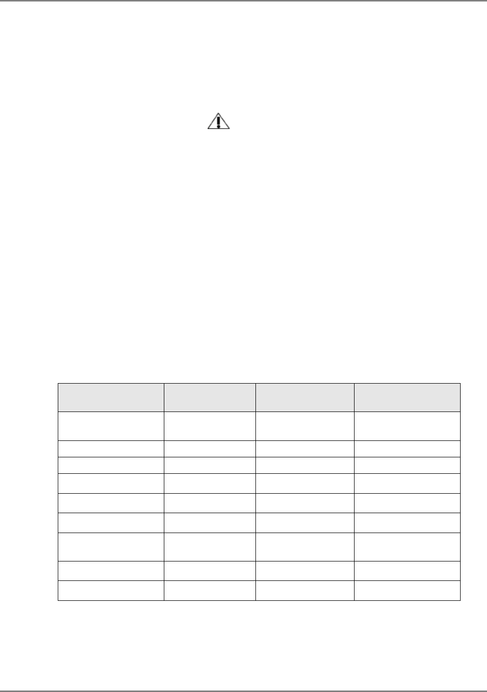
• Fiber optic cable - bundled fibers are terminated into the Base Units in the main
communication room. The fibers are then routed to each coverage locations where
individual fibers terminate into splice boxes. The splice box couples the installed fiber
into the remote units. Enough spare fibers should be installed to take into account
future expansion of the system.
For example, for three remote units, six fibers are required. However, to allow for future
expansion, it is recommended to install additional optic fibers to be connected to additional
RUs.
Continued on the following page...
Installation Guidelines Installation Conventions
MA2000 Installation and Configuration Guide 28
The following figure illustrates fiber optic routing to Remote Cabinets.
Figure 3-1. Illustration of Fiber Optic Routing
• For remote power supply configuration - cable bundles are routed from the main
communication room and individual wire pairs are terminated into the power feed of
individual units.
By providing power from a single distribution point, maintenance can be reduced and UPS
backup can be easily provided. The maximum distance from the source to the termination
spot is 1000 feet using 18 gauge wires.
In many locations local codes do not require power to be run through conduit if 100 watts or
less is used. Please consult the regulations in your local jurisdiction prior to deploying
remote power. When power cables require distances greater than 1000 feet 14 or 16 gauge
wire may be used.
• On each floor - the antennas are connected to the Remote Cabinet or MA2000-Lite system
using coax cables.

MA2000 Installation and Configuration Guide 29
4 S
Sy
ys
st
te
em
m
I
In
ns
st
ta
al
ll
la
at
ti
io
on
n
This chapter describes how the communication room and cabinet are installed. The individual
system elements and connections are described in the Chapter 2.
NOTE: Be sure to read the installation requirements (see
3.2) and Power Consumption related instructions
(see
3.3.3) before proceeding with the actual connections.
4.1 Pre-installation Instructions
In order to describe the installation process clearly, it will be described as consisting of two
logical parts:
A. Telecommunications room – installing the RIUs, BUs, SC-450 controller, and
the required
passive equipment
in the telecommunication room close to the RF
signal source. This installation may differ between single and multi-building
topologies.
B. Remote locations – two types of installations:
• MRC Cabinet
• MA2000-Lite
The installations for two basic topologies are described in detail: for single building and for multi-
building. By understanding the two generic installations you will be able to address any
variations in system deployment.
NOTE: For installations that include the MA NMS: Once the installation has been completed, it can be
verified using the MCT application (NMS User’s Guide) and the devices monitored using the NMS
Manager (NMS User’s Guide).
4.1.1 Unpacking and Inspection
This section provides instructions for opening the shipping boxes, verifying that all parts have
been received, and verifying that no shipping damage has occurred.
Unpack and inspect the cartons according to the following procedure
1. Open the shipping carton and carefully unpack each unit from the protective packing
material.
2. Check for signs of external damage. If there is any damage, call your MobileAccess service
representative.
4.2 Communication Room Installation
The Communication Room installation consists of the following basic steps:
1. Unpacking and inspecting the MA2000 units (see 4.1.1)
2. Mounting the RIUs, BUs and SC-450 controller in the mounting rack (see 4.2)

System Installation Communication Room Installation
MA2000 Installation and Configuration Guide 30
3 RF connections BTS/BDA connections.
4. RF connections to the Base Units.
5. Connecting the SC-450 control connections to the units
6. Connecting DC power to the units
4.2.1 Rack Installation General Instructions
NOTE: Usually, each operator installs the equipment that supports their services in a separate rack.
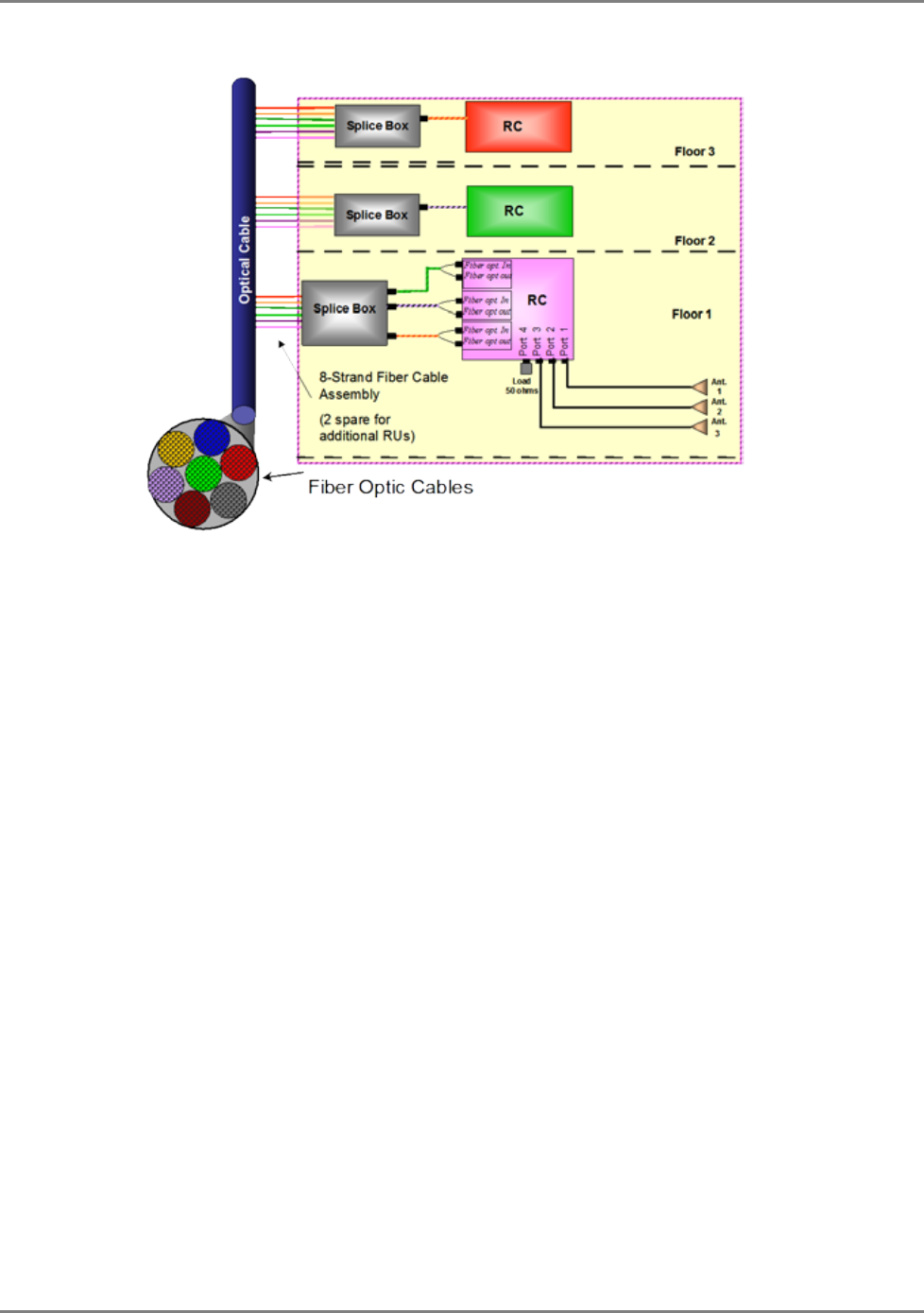
It is recommended to install the following MobileAccess system modules in a 19” rack in the
communication room
• RIU Chassis 3U, RIU Lite 2U
• BU 1U
• MA410/MA430 controller 1U
• Fiber Optic patch panel and splice tray
• Power supply/supplies (MobileAccess – 3U for each unit; units from other manufacturers
may vary in size)
Verify that the rack height can support all the units to be installed, where you may also want to
consider future expansions.
Figure 41 shows the recommended physical location of the MobileAccess elements in the rack in
order to facilitate and simplify the cabling
connections.
The configuration is for a single operator.
If the site is serviced by more than one operator, each operator often installs their equipment in
a separate rack.
NOTE: Note that the MobileAccess430 controller is at eye level to provide an easy view of the LED
indicators and LCD display and easy access to the local and remote monitoring connections.
System Installation Communication Room Installation
MA2000 Installation and Configuration Guide 31
The following figure shows a typical installation for a two field design.
Figure 4-1: Recommended Order in the Communication Room Rack
4.2.2 Rack Installation Safety Instructions
Review the following guidelines to help ensure your safety and protect the equipment from
damage during the installation.
• Only trained and qualified personnel should be allowed to install or replace this
equipment.
• Verify that ambient temperature of the environment does not exceed 50°C (122°F)
• To maintain a low center of gravity, ensure that heavier equipment is installed near the
bottom of the rack and load the rack from the bottom to the top.
• Ensure that adequate airflow and ventilation within the rack and around the installed
components so that the safety of the equipment is not compromised. It is recommended
to allow for at least about 2 cm of airspace between devices in the rack.
• Verify that the equipment is grounded as required – especially the supply connections.
System Installation Communication Room Installation
MA2000 Installation and Configuration Guide 32
4.2.3 BU Connections
This section describes the installation for the Base Units with the RF signal supplied from an MA
RIU Lite. If an RIU system is installed, refer to the RIU Installation and Configuration Guide for
detailed instructions on the RIU connections.
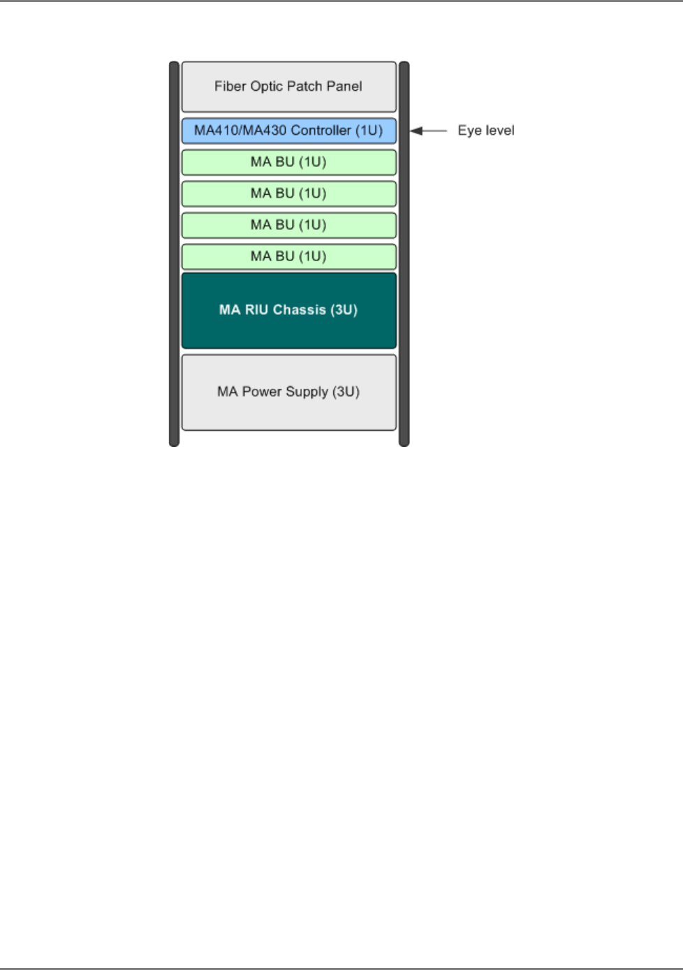
NOTE: It is assumed that the patch panel cabinet (SC/APC adaptors) for fiber optic cable connections is
installed in the rack near the BUs.
To connect the BU
1. Connect fiber jumper between splice tray and patch panel cabinet.
2. Connect fiber jumpers between the corresponding BU optical ports and the patch panel.
Figure 4-2. BU Front Panel Connections
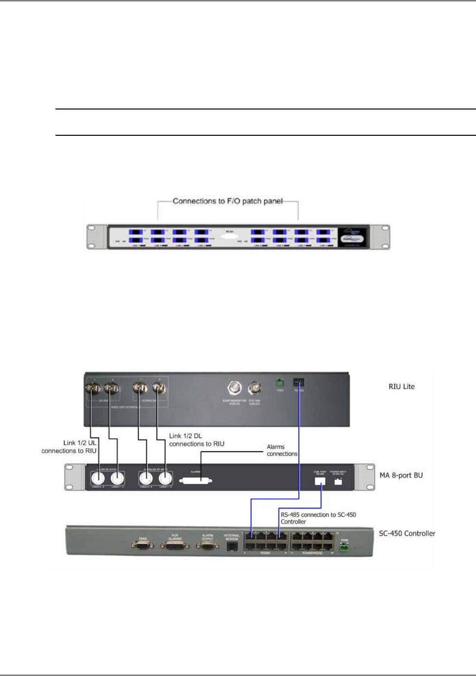
3. Connect the BU rear panel Uplink and Downlink ports to the corresponding ports on the
RIU rear panel (or to the RF ports from the passive interface if your system does not include
an RIU).
4. Connect the BU rear panel COM to the MA430 rear panel RS485 connector.
5. Connect the Power connection on the BU rear panel.
The following figure shows the BU connections to an MA RIU Lite and SC-450 controller.
Figure 4-3. BU Rear Panel Connections
System Installation Remote Cabinet Installation
MA2000 Installation and Configuration Guide 33
4.3 Remote Cabinet Installation
Mount and install the Remote Cabinet (RC) in one of the following configurations:
• Wallmount - on the wall in the communication room
• Rackmount – in a 19” rack in the
communication room
allocated to that area (sometimes
referred to as a secondary communication room).
The procedure varies slightly according to the MA2000 Cabinet model:
• Integrated power supply
• External power supply
The following sections describe both procedures.
NOTE: For installations that include MA850/MA860 units, refer to the MA850/MA860 Installation and
Configuration Guide for instructions on various installation options with the MA2000.
General Installation Instructions
The MA2000 Remote Cabinet units should be installed in a communication room that provides
access to authorized personnel only. The units are maintenance free. In the event of failure,
only authorized personnel should handle the units.
• Environmental Data - Maximum ambient operating temperature: 45° C
• Maximum ambient temperature in a rack: 45° C
4.3.1 MA2000 MRC Wall Mount Installation
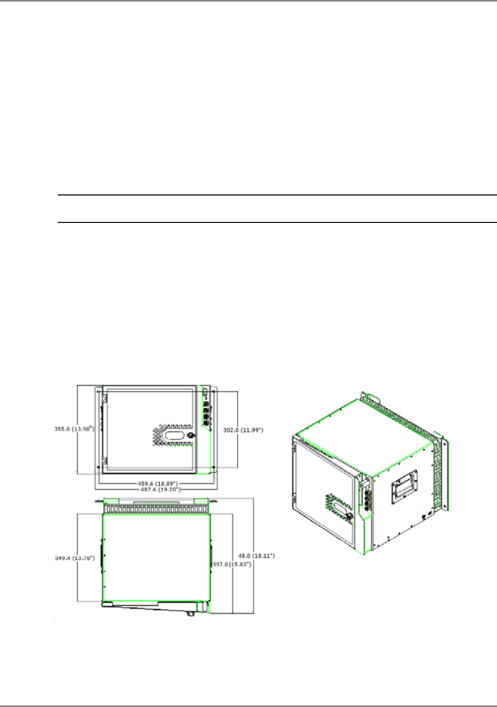
The following figures show the MA2000 Cabinet dimensions for a wall mount installation.
Figure 4-4. MA2000 Cabinet Wall Mount Dimensions
System Installation Remote Cabinet Installation
MA2000 Installation and Configuration Guide 34
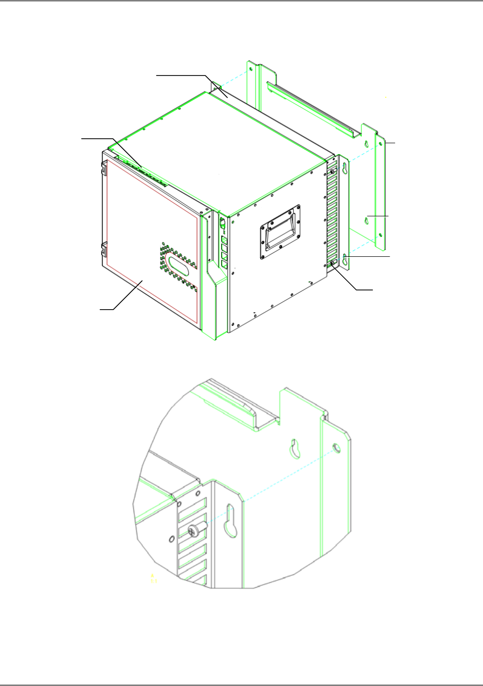
The wall installation MA2000 Remote Cabinet is supplied with a plate that is to be mounted on
the wall and a bracket that is assembled on the rear of the MA2000 system.
Figure 4-5. MA2000 System Wall Mount
Figure 4-6. Zoom of Mounting Holes
Plate
to be
mounted on the wall
Mounting Bracket
Location of anchors
Opening through
which connected optic
fibers are routed
Underside opening
through which power
connections are routed
Rear panel
bracket
Holes for
plate
to
bracket assembly

System Installation Remote Cabinet Installation
MA2000 Installation and Configuration Guide 35
Mount the MA2000 MRC on the wall as follows:
ATTENTION: The following instructions apply to an installation on a
concrete wall. For any other type of wall, contact MobileAccess.
NOTE: For installations that include an MA850/MA860 system, refer to the MobileAccess850/860
Installation and Configuration Guide.
1. For integrated power supply configurations only (for other configuration grounding is
optional), connect the cabinet GND according to section 4.3.2.
2. Using the plate as a guide, drill four holes for concrete anchors. Insert four concrete
anchors (McMaster-Carr catalogue number 92403A200, or equivalent).
3. Mount the Plate on the wall. Carefully and thoroughly fasten the anchors to the wall.
4. Assemble the Bracket onto the rear of the Remote Cabinet using the supplied screws.
5. Lift the MA2000 MRC and guide the rear ledge of the assembled bracket onto the plate
bracket.
6. Using the four screws, secure the RC Bracket to the Plate on the wall.
NOTE: Tighten the screws only as much as needed to secure the Bracket to the Plate. One should be
able to loosen the screws quickly if needed.
System Installation Remote Cabinet Installation
MA2000 Installation and Configuration Guide 36
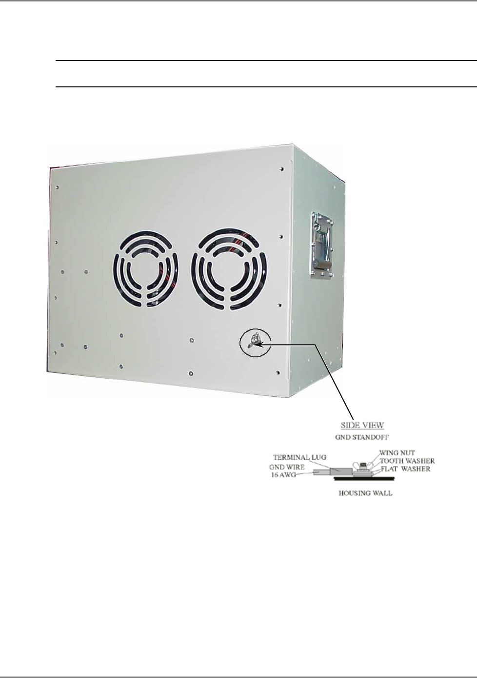
4.3.2 MRC Grounding - Integrated PS Wall Mount Model
NOTE: This procedure is only necessary for wall mount integrated power supply configuration (for other
configurations this procedure is optional).
The Ground screw is located at the rear of the unit.
Figure 4-7: Grounding Located at the Rear of the Unit
System Installation Remote Cabinet Installation
MA2000 Installation and Configuration Guide 37
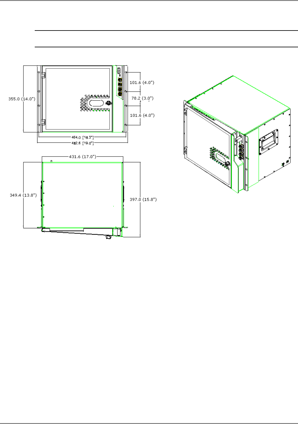
4.3.3 MRC 2000 Rack Mount Installation
NOTE: The cabinet requires a clearance of 10 cm above the unit. If a heating source is installed beneath
the MRC, a buffer must be placed between the cabinet and the surface.
The following figure provides the dimensions for the MA2000 Rack Model.
Figure 4-8. MA2000 Cabinet Rack Mount Assembly
System Installation Remote Cabinet Installation
MA2000 Installation and Configuration Guide 38
The MA2000 MRC Rack Mount model is supplied with the required brackets already assembled to
the sides of the cabinet as illustrated in the Figure 49 . MA2000 MRC Rack Model.
Simply, mount the MA2000 MRC in the rack and secure with the supplied screws.
Figure 4-9 . MA2000 MRC Rack Model
Rack brackets
System Installation Remote Cabinet Installation
MA2000 Installation and Configuration Guide 39
4.3.4 Fiber Optic Connections
NOTE: Keep in mind the rules for handling and connecting F/O cables. The F/O cables will be connected to
the associated BU in the communication room at a later phase.
1. Install splice box near Remote Cabinet.
2. Connect fiber optic cable to splice box and the SC/APC pigtails to each RU 2000 module.
3. For the downlink, connect the fiber optic cable pigtails from splice box coming from the BU
port to the corresponding RU port (routing the optic fibers so they will fit through the top
opening in the door.)
4. For the uplink, connect the fiber optic cable pigtails from splice box from the RU (routing the
optic fibers so they will fit through the top opening in the door), to the uplink port that
connects to the BU.
The internal power connections and other connections should already be
connected.
Figure 4-10. MA2000 RU Fiber Optic and internal power connections
Power connection
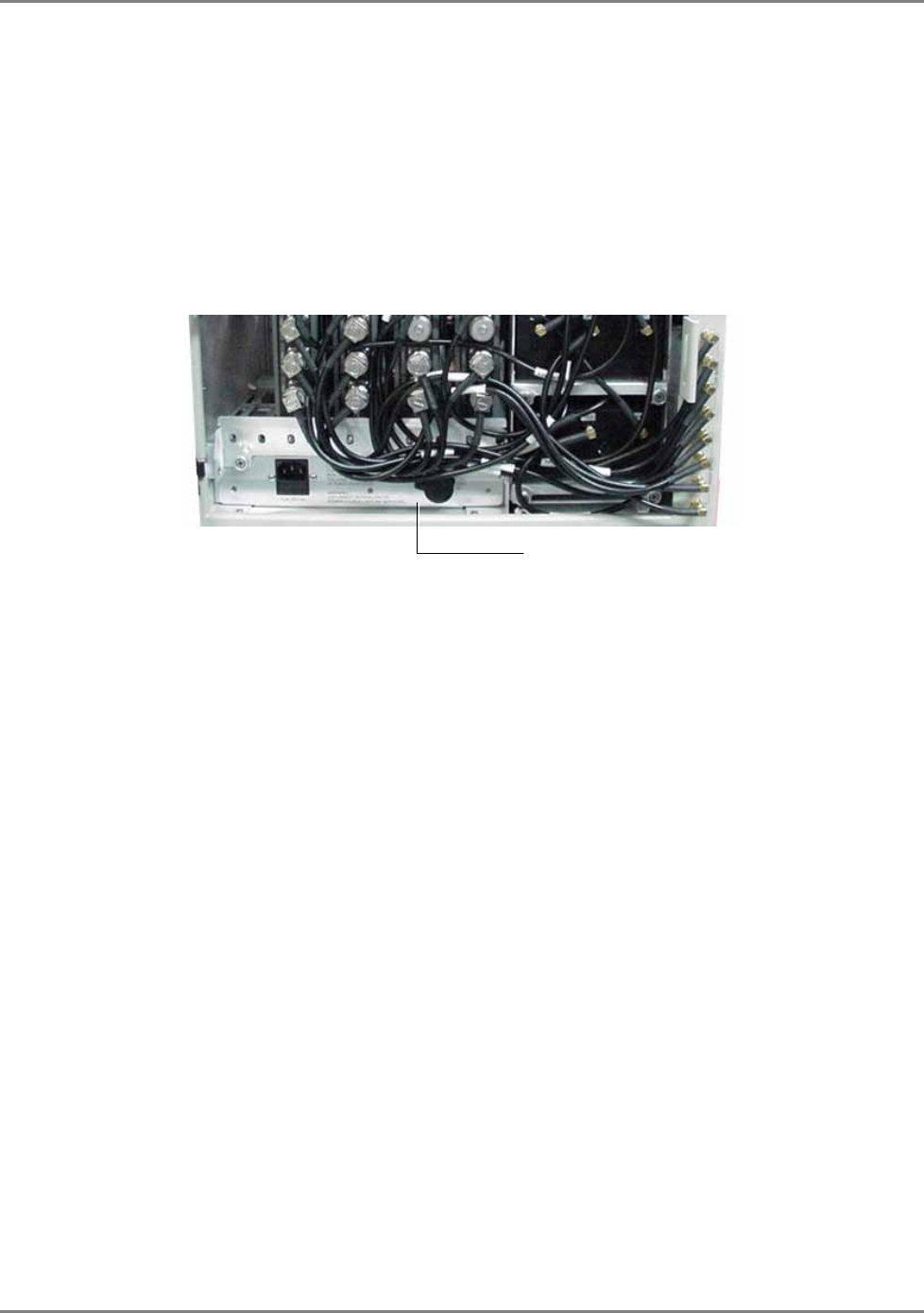
System Installation Remote Cabinet Installation
MA2000 Installation and Configuration Guide 40
4.3.5 Power Connections
The power connections vary depending on whether the configuration is for an integrated power
supply or for external power supplies.
4.3.5.1 Integrated Power Supply model
• Connect the AC power connector to the connector on the internal plate as illustrated
below. The power source may be: 230 VAC, 115 VAC (an AC/DC converter is built into
the chassis).
• You may also connect a backup battery of 48V to the battery connector. This is an
optional connection.
Figure 4-11. Partial View of system illustrating location of power connections
4.3.5.2 External Power Supplies Model
The external power source may be a central source with cables routed to each RU, or RU
dedicated power supplies locally installed.
• PS = 24 VDC to 48 VDC.
• Connect each power connection to the appropriate connector on the remote cabinet.
4.3.6 Antenna Connections
• For systems
without
MA850/MA860 modules - connect the antenna connections to the
RC antenna ports
• For systems with MA850/MA860 modules - refer to
MA850/MA860 Installation Manual
Battery
connection
( l)
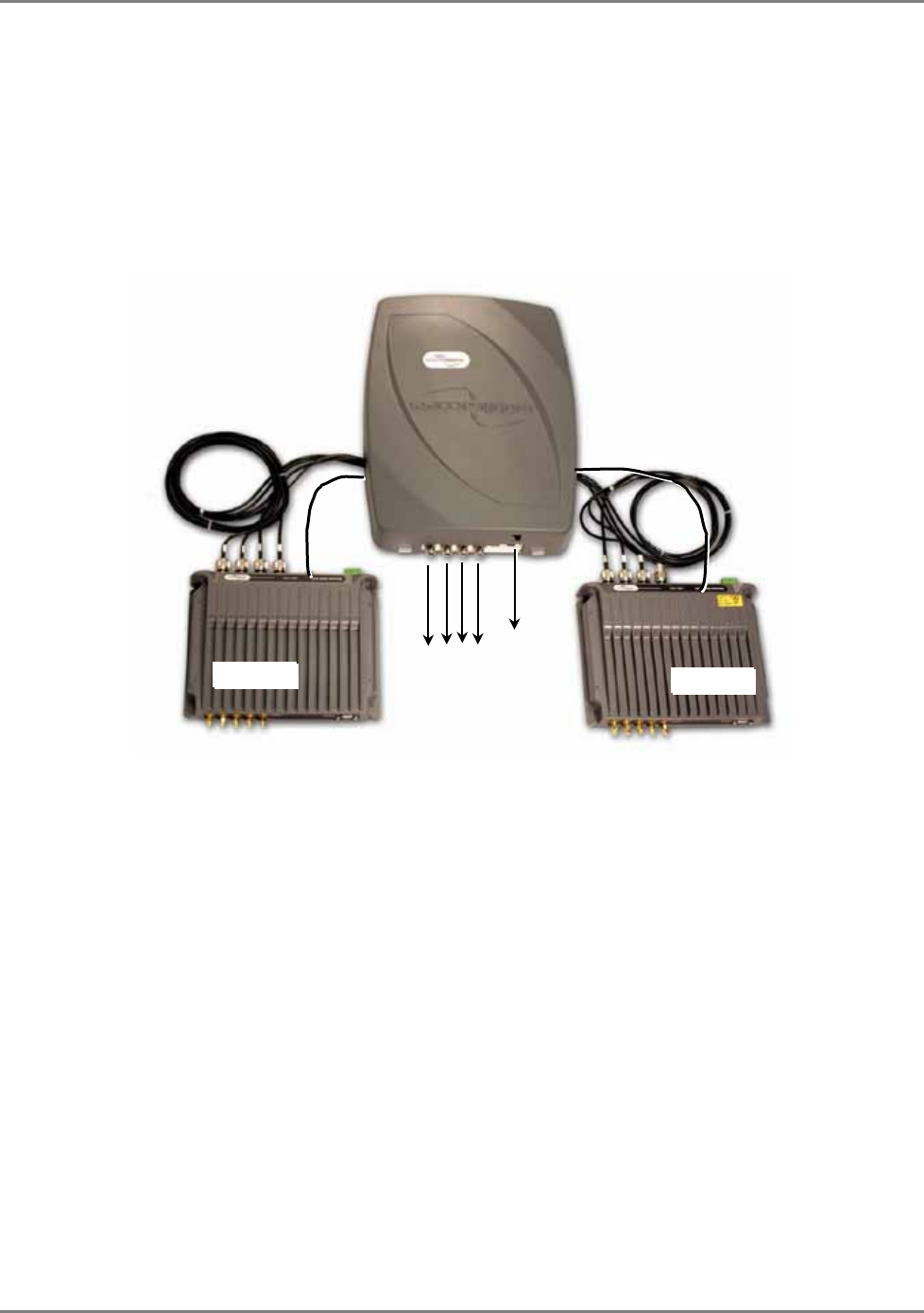
System Installation MA2000-Lite Installation and Connections
MA2000 Installation and Configuration Guide 41
4.4 MA2000-Lite Installation and Connections
MA2000-Lite is designed as a wall-mount installation – usually located in the communication
shaft of the corresponding floor. The remote units are mounted externally to the MA2000-Lite
device and their antenna outputs are connected to either side of the MA2000-Lite device. The
combined outputs are then connected to the antennas in the covered area.
The following figure illustrates MA2000-Lite connections to two RUs.
Figure 4-12. MA2000-Lite System Coax Connections
MA2000-Lite enclosure
RU 2000
Antennas
RU 2000 PWR
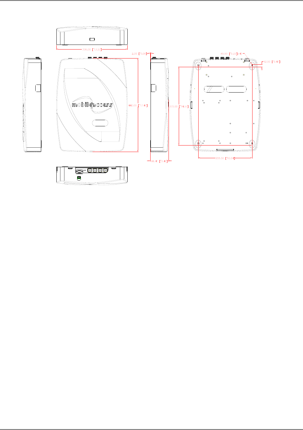
System Installation MA2000-Lite Installation and Connections
MA2000 Installation and Configuration Guide 42
The following figure shows the RIU Lite mechanical drawing
Figure 4-13. MA2000- Lite Mechanical Dimensions
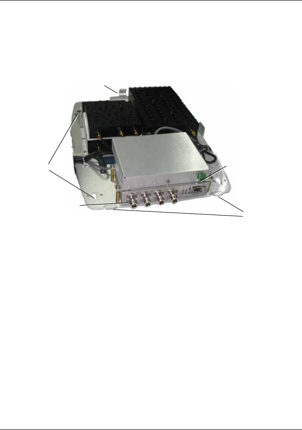
System Installation MA2000-Lite Installation and Connections
MA2000 Installation and Configuration Guide 43
4.4.1 Mounting MA2000-Lite
In order to mount MA2000-Lite on the wall, the cover is first removed, the tray and all installed
elements are secured to the wall and the top cover assembled again.
1. Remove the top cover by pulling it towards the rear bracket and lifting it over the front
brackets. The tray and all its assembled components are displayed. The installed filters vary
depending on the RU models in the installation.
Figure 4-14. MA2000-Lite Prepared for Mounting
2. Depending on the tools you use:
• Either measure the distance between the four wall mount holes and drill the required
holes in the wall and insert the screws, or
• Hold the tray up against the wall and simply drill the screws in the holes.
3. Mount each MA2000 RU on the wall, on the corresponding side of the MA2000-Lite unit.
4. Reassemble the MA2000-Lite cover by fitting it over the
front tabs
and pressing down gently
at the rear.
Power connection
Rear tab
Mounting holes
(2x on each side)
Front tabs
Antenna
connections
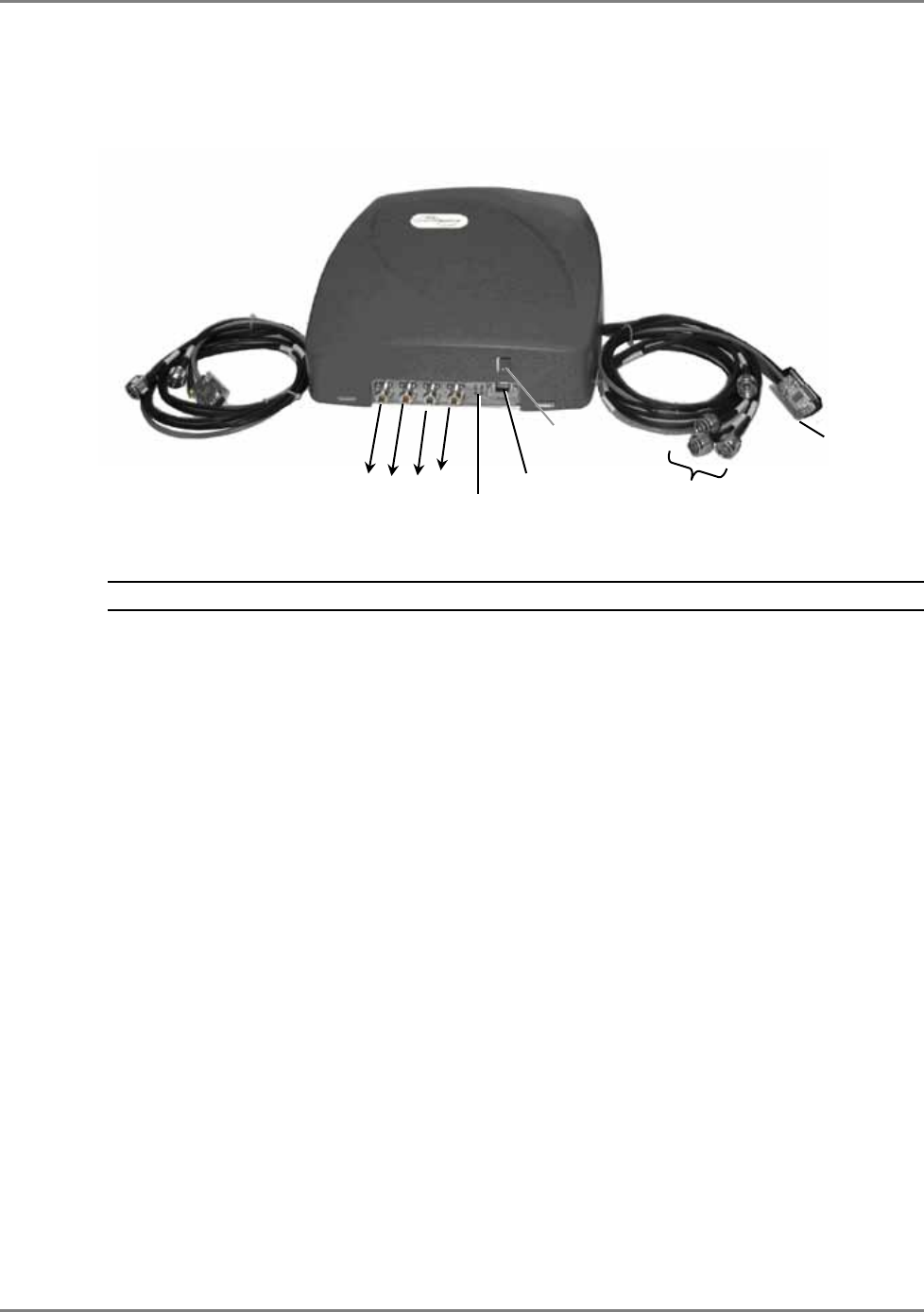
System Installation MA2000-Lite Installation and Connections
MA2000 Installation and Configuration Guide 44
4.4.2 MA2000-Lite Connections
This section describes the MA2000-Lite enclosure and its' external connections.
NOTE: It is not required to perform the following procedures in any particular order.
1. Connect the antenna cables to the front panel antenna connectors.
2. Connect the DC power.
3. Connect each of the side cable N-type antenna connectors to the antenna connectors of
the corresponding RU.
4. Connect each of the side cable D-type connector to the front panel RS232 connectors of
the corresponding RU.
Connections to MA2000 RU
front panel RS232 and
antenna connectors
(1) To Antennas
(2) Power
LEDs
Control
(4) To MA2000 RU
front panel RS232
connector
(3) To MA2000 RU
front panel antenna
connections

MA2000 Installation and Configuration Guide 45
5 U
Up
pg
gr
ra
ad
di
in
ng
g
a
an
nd
d
C
Co
on
nf
fi
ig
gu
ur
ra
at
ti
io
on
n
E
Ex
xa
am
mp
pl
le
es
s
MobileAccess2000 provides an entry level cost effective solution for current services and
support for future services from the same or different operators. Support for additional bands is
implemented by an RU module and RU specific hardware designed to prevent interference with
other existing bands in the coverage area.
For support for additional services, connect the corresponding RU and hardware (Cavity Filter,
Duplexer, etc.) to the 8x4 Module and to the external coax infrastructure.
NOTE: It is required to order an Accessory Kit for each new unit to be added to the installation. The kit
includes cables for connecting the MA2000 RU or MA1200 Add-On units to the required filters. Because of
the differences in cable length requirements, the accessory kit differs for units designated to be installed in
2000 Cabinets and for those designated to be installed with MA2000-Lite systems.
This chapter provides several examples of the most common configurations and their
connections. As systems are expanded for additional services, refer to the provided diagrams for
a description of the connections between the Remote Units (referred to as RHU 2000), the
interface devices (Filters, etc.) and the 4x8 Combiner.
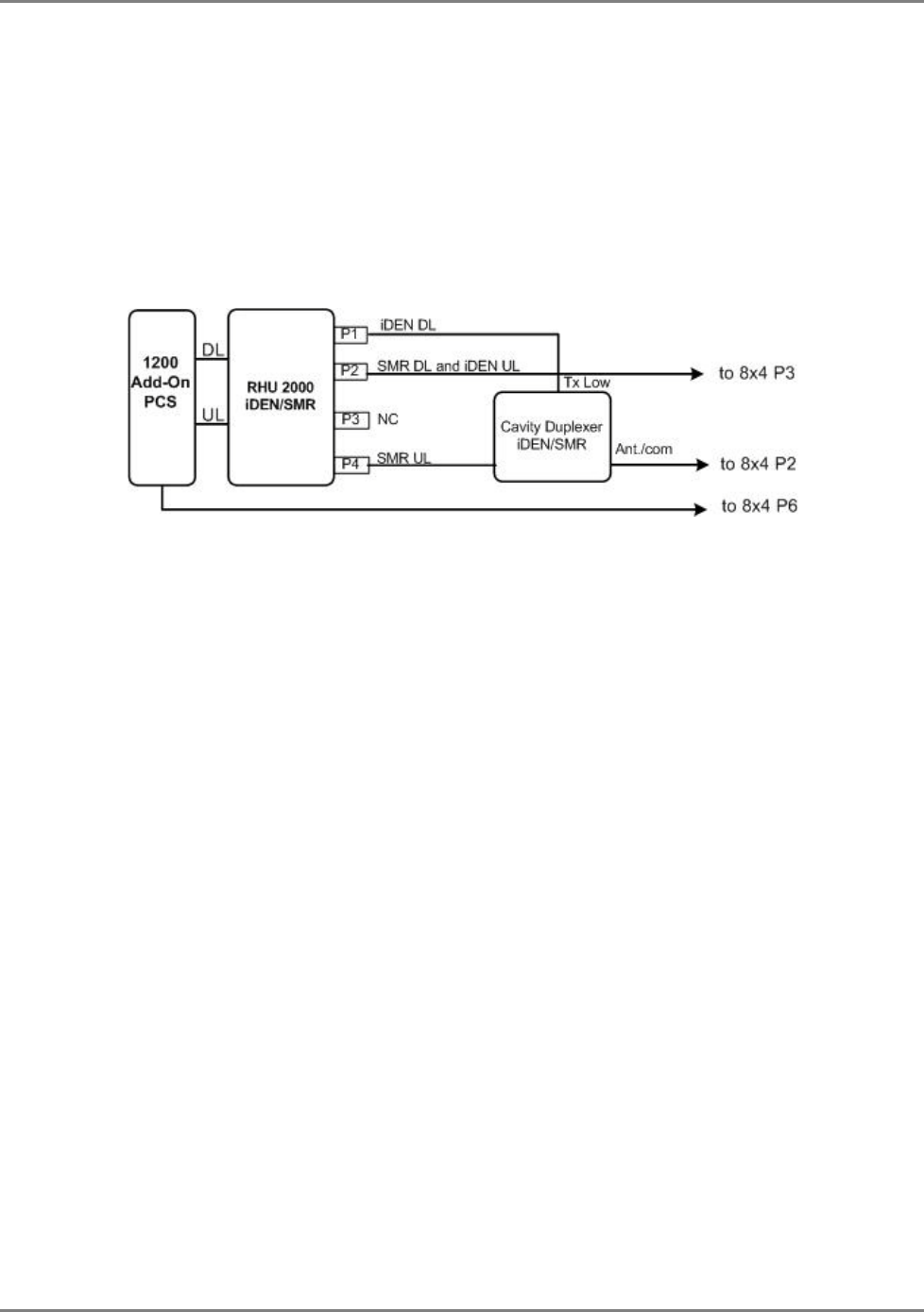
Upgrading and Configuration Examples Common USA Configurations
MA2000 Installation and Configuration Guide 46
5.1 Common USA Configurations
5.1.1 iDEN/SMR with PCS Add-on
iDEN and SMR coverage is implemented by one remote unit. This type of configuration was
designed to meet Nextel’s existing needs. MA1200 add-on module for PCS support can be
integrated into the solution at any time in order to meet future needs.
The following figure describes the port connections between the remote units, add-on, and 8x4
Combiner.
Figure 5-1. iDEN/SMR and PCS Connections
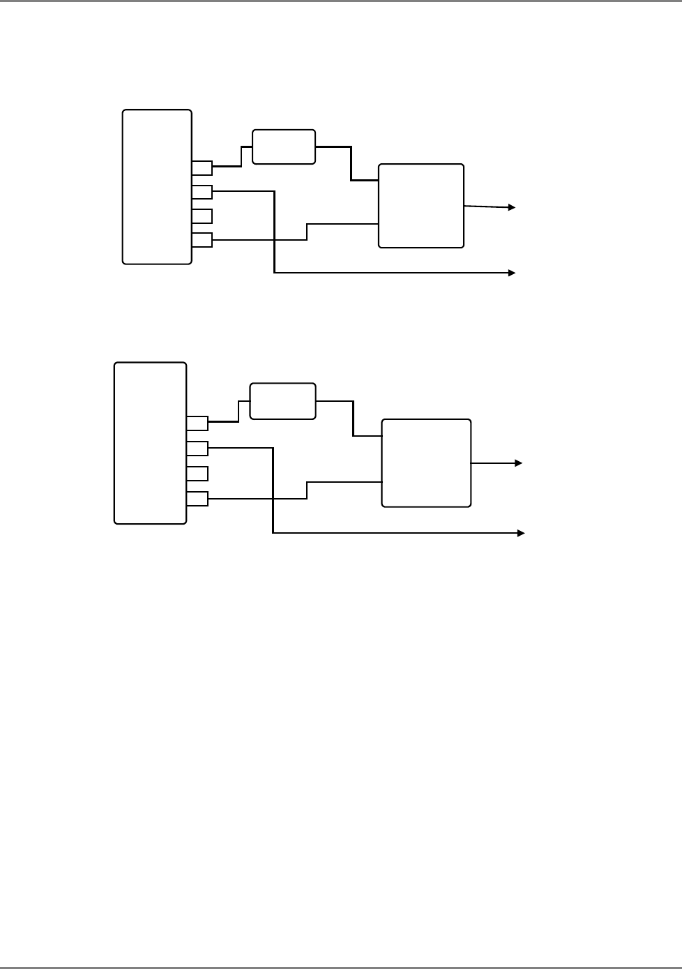
Upgrading and Configuration Examples Common USA Configurations
MA2000 Installation and Configuration Guide 47
5.1.2 Cell/PCS
For infrastructures supporting a single Cell band and PCS, connect the RU according to the
following figure.
Figure 5-2. Single Cell/PCS Connections
For infrastructures supporting two Cell bands and a PCS band, connect the second Cell/PCS
services RU according to the following figure.
Figure 5-3. Additional Cell/PCS Connections
P1
P4
P3
P2
RHU 2000
CELL/PCS Cavity
Cell Duplexer
N.C. 8x4 P1
8x4 P5
Cavity
Cell DL
Tx
Rx
Com
P1
P4
P3
P2
RHU 2000
CELL/PCS Cavity
Cell Duplexer
N.C. 8x4 P4
8x4 P8
Cavity
Cell DL
Tx
Rx
Com
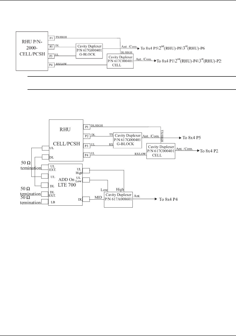
Upgrading and Configuration Examples Common USA Configurations
MA2000 Installation and Configuration Guide 48
5.1.3 Cell/PCSH
The following figure provides a description of how to connect up to three Cell/PCSH services.
Note: In cases requiring more than one RHU, connect the additional units according to 2nd and 3rd RHU
configuration.
5.1.3.1 Cell/PCSH and LTE 700
The following figure shows the connections for a configuration consisting of a 700 LTE Add-On
unit with external filter and Cell/PCSh RHU.
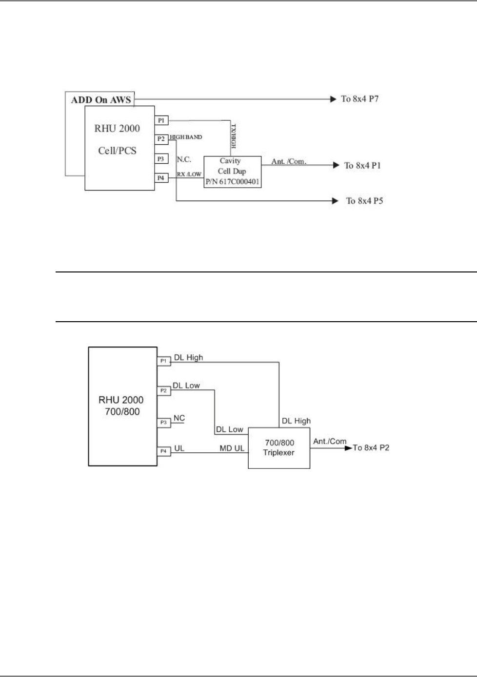
Upgrading and Configuration Examples AWS Add-On
MA2000 Installation and Configuration Guide 49
5.2 AWS Add-On
The following figure shows the duplexer and 8x4 combiner connections for configurations with
an AWS Add-On unit.
5.3 Public Safety 700/800
NOTE: Both the MA2000 Public Safety 700/800 RHU and the corresponding filter unit are installed
EXTERNALLY on the Cabinet. For information on the installing and configuring the MA2000 Public Safety
700/800 RHU refer to the
MobileAccess2000 700/800 Public Safety RHU Quick Installation Sheet
provided
with the unit.
The installation connections are as follows.
Figure 5-4. 700/800 RHU Configuration
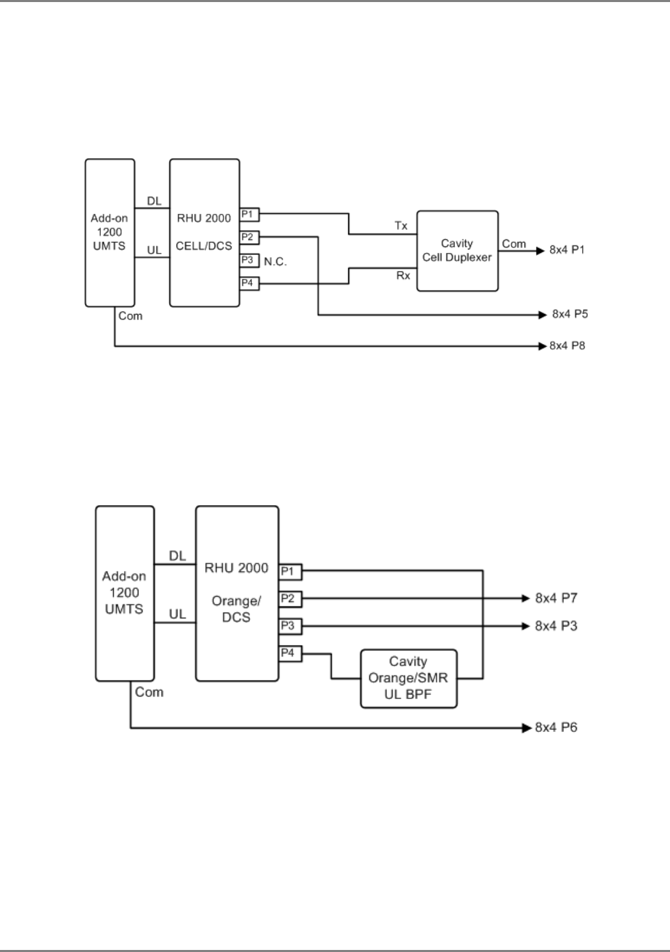
Upgrading and Configuration Examples Typical International Configurations
MA2000 Installation and Configuration Guide 50
5.4 Typical International Configurations
MA2000-Lite supports Cell/DCS and DCS. UMTS support can be added through MA1200 Add-On.
5.4.1 Typical Asian Configuration: Cell/DCS+ UMTS
Figure 5-5. Cell/DCS and UMTS Configuration
5.4.2 Typical European & Middle East Configuration: EGSM/DCS + UMTS
Configuration
Figure 5-6. Typical European & Middle East Configuration
5.4.3 iDEN
iDEN support is provided through MA2000 Cabinet configurations.
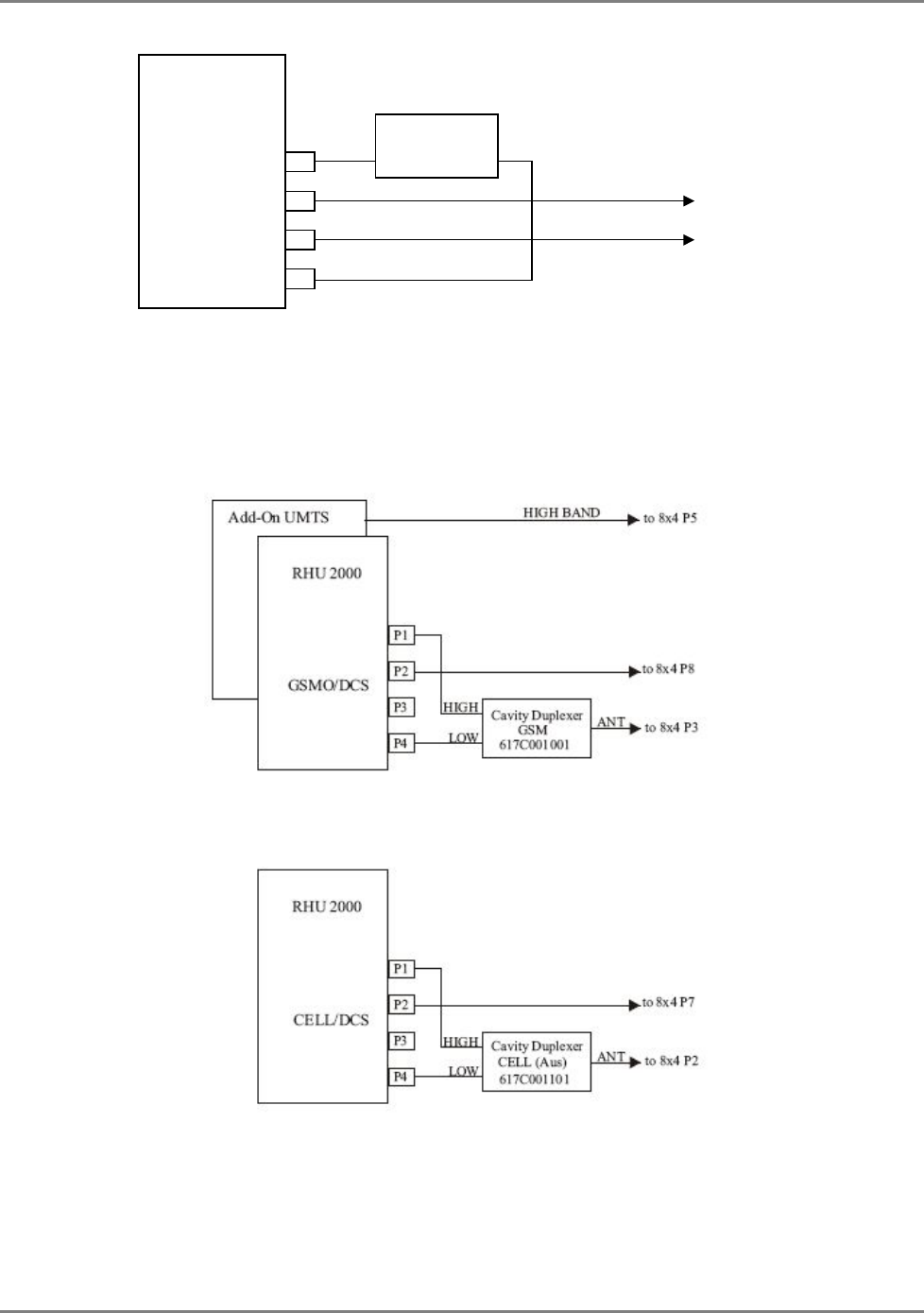
Upgrading and Configuration Examples MA2000-Lite Cell/DCS and GSM/DCS Config for Telstra
MA2000 Installation and Configuration Guide 51
5-7. iDEN Configuration
5.5 MA2000-Lite Cell/DCS and GSM/DCS
Config for Telstra
RHU 2000
iDEN
P1
P2
P3
P4
Cavity
iDEN
DL BPF
to 8x4 P6
to 8x4 P2

MA2000 Installation and Configuration Guide 52
6 A
Ap
pp
pe
en
nd
di
ix
x
:
:
S
Sy
ys
st
te
em
m
S
Sp
pe
ec
ci
if
fi
ic
ca
at
ti
io
on
ns
s
RF Parameters
RF Frequency Range
Services Frequency Range
Uplink Downlink
CELL 824-849 869-894
iDEN 806-824 851-869
GSM 890-915 935-960
E-GSM 880-915 925-960
Telstra 850M 824-849 869-890
SMR 896-902 929-941
DCS 1710-1785 1805-1880
PCS 1850-1910 1930-1990
G-PCS 1850-1915 1930-1995
UMTS 2100 1920-1980 2110-2170

Appendix : System Specifications RF Parameters
MA2000 Installation and Configuration Guide 53
Low Band
RF Parameters Low Band
RU 2000
CELL
TDMA/CDMA/WCDMA SMR
800 iDEN 800
Sprint
GSM/
E-
GSM
SMR
900 IDEN 900
Sprint
D U D U D U D U D U D U
Max output PWR per
antenna port
1 (comp)
16
14 10 12 14
10
2 carriers
13
11 7 9 11
7
4 carriers
10
8 4 6 8
4
8 carriers
7
5 1 3 5
1
12 carriers
5
3 -1 1 3
-1
Mean Gain(dB)*
16
7 14 7 10 7 12 7 14
7
10 7
Pin (dBm)*
0
0 0 0 0 0
Input IP3 (dBm)
AGC OFF Min
-5 -5 -5 -5 -5 -5
Input IP3 (dBm)
AGC ON Min
5 5 5 5 5 5
SFDR** (dB)
71 72 72 64 71 71
Max Intermod Distortion
(dBm)
-13
-13 -13 -36 -13 -13
Max Nf (dB)
20 20 20 20 20 20
Gain Flatn. (dB) ± 2.0

Appendix : System Specifications RF Parameters
MA2000 Installation and Configuration Guide 54
High Band
*Factory set mean gain BU-RHU without RIU. May be field adjusted using system controller. ** SFDR for CDMA services is calculated in 100Kb/sec
RF Parameters High Band
RU 2000
DCS PCS CDMA/WCDMA PCS GSM/TDMA
D U D U D U
Max output PWR
per antenna port
1 (comp) 14 14 16
2 carriers 11 11 13
4 carriers 8 9 10
8 carriers 5 6 7
12 carriers 3 4 5
Mean Gain(dB)* 14 3 14 3 14 3
Pin (dBm)* 0 0 2
Input IP3 (dBm)
AGC OFF Min -6 -6 -6
Input IP3 (dBm)
AGC ON Min 3 3 3
SFDR** (dB) 64 66 64
Max Intermod Distortion (dBm) -30 -13 -13
Max Nf (dB) 20 20 20
Gain Flatn. (dB) ± 2.0

Appendix : System Specifications RF Parameters
MA2000 Installation and Configuration Guide 55
RF Parameters MA1200 Add-on
MA1200 ADD-ON
G-PCS CDMA/WCDMA G-PCS GSM/TDMA UMTS***
D U D U D U
Max output PWR
per antenna port
1 (comp) 20 21 21
2 carriers 17 18 18
4 carriers 14 15 15
8 carriers 11 12 12
12 carriers 9 10 10
Mean Gain(dB)* 20 3 20 3 21 3
Pin (dBm)* 0 1 0
Input IP3 (dBm)
AGC OFF Min -7 -7 -7
Input IP3 (dBm)
AGC ON Min 3 3
SFDR** (dB) 66 64 66 70
Max Intermod Distortion (dBm) -13 -13 ***
Max Nf (dB) 20 20 20
Gain Flatn. (dB) ± 2.0
*Factory set mean gain BU-RHU without RIU. May be field adjusted using system controller.
** SFDR for CDMA services is calculated in 100Kb/sec
*** UMTS Compiles with 3GPP TS 25.106 V5.0.0 (2002-03) Table 9.4 spectrum emission mask

Appendix : System Specifications System Specs
MA2000 Installation and Configuration Guide 56
System Specs
Fiber Optic Specifications
Optical output power <3.0mW
Max. Optical budget 2 dB for fiber + 1 dB for connectors (assumed) = 3 dB total
Optical loss per mated-pair
connectors 0.5dB (max)
Optical Connector SC/APC
Fiber type 9/125 SM
Wavelength 1310±10nm
Maximum distance between
Base Unit and Remote Cabinet 2Km
Absolute Maximum Rating
Total Input RF Power to BU 10dBm
Total Input RF Power to RU 20dBm out-of-band
-10dBm in-band
Power Supply VDC 60VDC
Temperature Specifications
Operating 0°C to +50°C (32°F to 122°F)
Storage -20°C to 85°C (-4°F to 185°F)

Appendix : System Specifications Specifications of Units
MA2000 Installation and Configuration Guide 57
Specifications of Units
6.1.1 MA 2000 MRC Remote Hub
Supported Units : A total of up to five Remote Units (one being a MA 1200 Add-on module)
(not including MA 850/860 which is installed externally)
RF antenna connections : Four N-type female antenna connections
Input power
Local powering : 230 VAC, 115 VAC (an AC/DC converter is built into the chassis).
Remote powering : 20 to 48VDC to external connectors on chassis
Power consumption : 25W
Physical
Mounting : Wallmount and rackmount
Dimensions : 355 x 482.6 x 397mm (13.97” x 19” x 15.63” )
Weight (4 modules) : ~35Kg (~77 lb)
6.1.2 MA 2000 Lite
Supported Units : External connections to two Remote Units
(MA 1200 Add-ons each unit)
RF antenna connections : Four N-type female antenna connections
Power consumption : 3W max (housing only with no remote units)
Physical
Mounting : Wallmount
Dimensions : 442 x 336 x 86.41mm (17.4” x 13.23” x 3.4” )
Weight : 5.5Kg (12.1lb)
6.1.3 MA 2000 Remote Unit
Supported services : Two services corresponding to the model
Power:
Input power : 20 to 48V DC
Power consumption : 29W
RF connections : To Antenna (via hub) - N-type Female, 50 ohm
: To MA 1200 add-on - SMA 50 ohm
Optic connections : SC/APC optic connections
Remote management : SNMP, NMS via Base Unit connection to SC-450 controller.
6.1.4 MA 1200 Add-On Specifications
Supported services : Single service corresponding to the model
RF Connections: : To RHU - SMA 50 ohm
Power:
Input power : 25-48VDC
Power consumption : 50W
Remote management : SNMP, NMS via RHU connection
Dimensions 27.9x22.0x6.9cm (10.98”x8.66”x2.71”)
Weight 2.8Kg (6.2 lb)
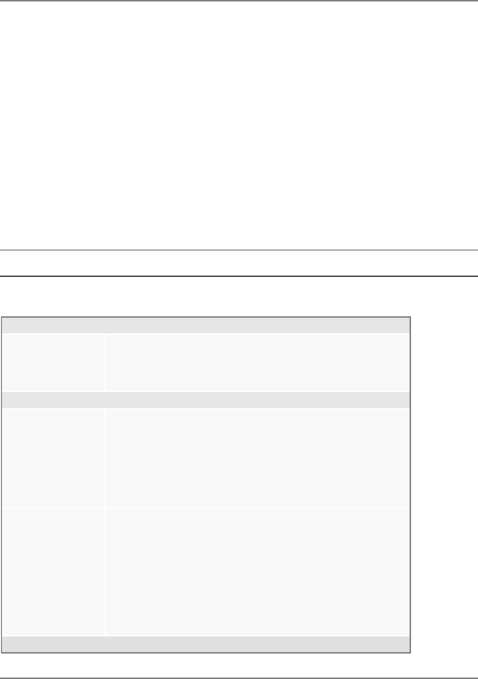
Appendix : System Specifications Ordering Information
MA2000 Installation and Configuration Guide 58
6.1.5 Base unit Specifications
Models: 4-port model, 8-port model (shown above)
Supported services: Wideband device supporting all services supported by MA systems
RF (total Input): 10 dBm max
Power:
Input power 20 to 48V DC
Power consumption 14W (8-port BU)
RF connections N-type Female, 50 ohm – interface to RIU or to passive BTS interface
N-type Female, 50 ohm – interface to antennas
Optic connections Four or eight (depending on the model) SC/APC optic connections
Remote management SNMP, NMS via connection to SC-450 controller.
Physical
Dimensions 48.26x4.44x29.97cm (19”x1Ux11.8”)
Weight 2.82Kg (6.2lb)
Ordering Information
NOTE: The information listed below is updated up to the document publishing date. Refer to the MA2000 datasheet for
the most updated ordering information.
Remote HUBs
2000-RC-RP
2000-RC-LP
2000-MINI-ENC
Remote Cabinet - all services, Remote powering
Remote Cabinet - all services, Local powering
2000 enclosure supporting 2 modules
Dual Band RF Modules, add-on ready
MA2000 Cabinet
2000-CELL-DCSE
2000-CELL-PCSE
2000-GSMO-DCSE
2000-IDEN-SMR
2000-E-GSM-DCS
Dual band Cell/DCS 1 port for cabinet, enhanced power
Dual band Cell/PCS 1 port for cabinet, enhanced power
Dual band GSM DCS 1port for cabinet, enhanced power
Dual band iDEN/SMR for cabinet
Dual band EGSM/DCS 1 port for cabinet
MA2000-Lite
2000-CELL-DCSEL
2000-CELL-PCSEL
2000-E-GSM-DCSL
2000-GSMO-DCSEL
2000-IDEN-SMR-L
2000-CELL-DCSLT
2000-GSM-DCSLT
Dual band Cell/DCS 1 port for Lite, enhanced power
Dual band Cell/PCS 1 port for Lite, enhanced power
Dual band GSM/DCS 1 port for Lite, enhanced power
Dual band GSM DCS 1 port for Lite, enhanced power
Dual band iDEN/SMR for Lite
Dual band Cell/DCS 1 port for Lite enhanced power for Telstra
Dual band GSM/DCS 1 port for Lite enhanced power for Telstra
MA1200 Add-On

Appendix : System Specifications Ordering Information
MA2000 Installation and Configuration Guide 59
1200-PCS-AO-CB
1200-G-PCS-AO-CB
1200-UMTSE-AO-CB
1200-PCS-AO-LT
1200-UMTSE-AO-LT
Add-on RHU - PCS service for cabinet
Add-on RHU supporting a PCS w/G-block for 2000 cabinet
Add-on RHU - UMTS service for cabinet
Add-on RHU - PCS service for Lite
Add-on RHU - UMTS service for Lite
MobileAccess Universal Base Units
WB-B8U
WB-B4U Wide Band Base 8 Unit supporting 8 RHUs
Wide Band Base 4 Unit supporting 4 RHUs
Network Controller
SC-450 Network Controller –Ethernet/IP Interface
410
430 Network Controller – Serial Interface (dial-up)
Network Controller –Ethernet/IP Interface
Network Management System
NMS-SW-SERVER
NMS-SW-MFEE GUI and server S/W package (one per site)
NMS annual S/W maintenance fee (per 430-CTLR)

Appendix : System Specifications Ordering Information
MA2000 Installation and Configuration Guide 60
MobileAccess Radio Interface Unit (RIU)
RIU-IM
RIU-BTSC-CELL
RIU-BTSC-IDEN
RIU-BTSC-PCS
RIU-BTSC-G-PCS
RIU-BTSC-SMR
RIU-BTSC-GSM
RIU-BTSC-E-GSM
RIU-BTSC-DCS
RIU-BTSC-UMTS
RIU-BDAC-CELL
RIU-BDAC-IDEN
RIU-BDAC-PCS
RIU-BDAC-G-PCS
RIU-BDAC-SMR
RIU-L-IDEN-SMR-G-PCS1
Radio Interface Unit
BTS Conditioner for Cellular
BTS Conditioner for iDEN
BTS Conditioner for PCS
BTS Conditioner for PCS w/ G-Block support
BTS Conditioner for SMR-Paging
BTS Conditioner for GSM 900MHz
BTS Conditioner for EGSM 900MHz
BTS Conditioner for DCS 1800MHz
BTS Conditioner for UMTS 2100MHz
BDA Conditioner for Cellular
BDA Conditioner for iDEN
BDA Conditioner for PCS
BDA Conditioner for PCS w/ G-Block support
BDA Conditioner for SMR-Paging
RIU Lite for iDEN800,SMR 900,PCS1900 w/G-Block, support 1BU8
RIU-L-CELL-PCS1 RIU Lite Cellular 800,PCS 1900
Power Supply
LPS-48V-66W Local AC/DC Converter 66W
LPS-48V-100W
AK-PWR-CORD-EU
AK-PWR-CORD-UK
Local AC/DC Converter 100W
AC Power cord for 66W & 100W power supplies, European connector
AC Power cord for 66W & 100W power supplies, UK connector
61 MA2000 Installation and Configuration Guide
This page is intentionally left blank…