Corning Optical Communication GX2325 High Power Remote Unit 2.3/2.5GHz User Manual
Corning Optical Communication Wireless High Power Remote Unit 2.3/2.5GHz Users Manual
Users Manual

GX 40 W Dual-Band 2.3/2.5 GHz
Remote Unit
User Manual
Corning Optical Communications User Manual | CMA-601-AEN | Page 2
Warranties
Hardware Warranty
Corning Optical Communications LLC (
“
Corning
”
) warrants to
the original purchaser (
“
Customer
”
) that for the duration of
the warranty period, one (1) year, commencing on the date of
shipment of the Hardware, unless otherwise agreed in writing
by Corning (the
“
Hardware Warranty Period
”
), the Hardware
furnished by Corning shall be free in all material respects from
defects in material and workmanship, and shall conform to
the applicable portions of the Specifications, as defined below
(the
“
Hardware Warranty
”
). If notified by Customer of any
such defects in material or workmanship or nonconformity
with applicable portions of the Specifications within the
Hardware Warranty Period, Corning shall promptly, at its own
election and expense, repair or replace any such Hardware
proven to be defective under the terms of this Hardware
Warranty. Such repair or replacement shall be Customer
’
s sole
remedy and Corning
’
s sole obligation in the event this
Hardware Warranty is invoked. If any components comprising
a part of the Hardware are replaced or repaired during the
Hardware Warranty Period, the Hardware Warranty Period for
such repaired or replaced components shall extend to the
longer of (i) the balance of the Hardware Warranty Period or
(ii) three (3) months from the date of repair or replacement.
For purposes of this Warranty,
“
Specifications
”
shall mean the
specifications and performance standards of the Products as
set forth in documents published by Corning and delivered to
Customer which contain technical specifications or
performance standards for the Products.
If Customer invokes this Hardware Warranty, it shall notify
Corning promptly of the claimed defect. Customer will allow
Corning to inspect the Hardware at Customer
’
s location, or to
return the Hardware to Corning
’
s closest repair facility. For
Hardware returned to Corning
’
s repair facility, Customer shall
be responsible for payment of all transportation and freight
costs (including insurance) to Corning
’
s repair facility, and
Corning shall be responsible for all transportation and freight
costs (including insurance) incurred in connection with the
shipment of such Hardware to other repair facilities of
Corning and/or its return to Customer.
Notwithstanding the foregoing, in no event will Corning be
liable for damage to products resulting from improper
handling during or after shipment, misuse, neglect, improper
installation, operation or repair (other than by authorized
Corning personnel), alteration, accident, or for any other cause
not attributable to defects in materials or workmanship on
the part of Corning. Corning shall not reimburse or make any
allowance to Customer for any labor charges incurred by
Customer for replacement or repair of any goods unless such
charges are authorized in advance in writing by Corning.
Software Warranty
Corning Optical Communications LLC (“Corning”) warrants to
the original purchaser (“Customer”) that for the duration of the
warranty period, one (1) year, commencing on the date of
shipment of the Software, unless otherwise agreed in writing by
Corning (the “Software Warranty Period”), the Software shall
conform with, and perform the functions set forth in the
Specifications, and shall be free from defects in material or
workmanship (the “Software Warranty”). In the event the
Software is proven to be defective under the terms of this
Software Warranty, Corning shall correct such defects or failure
and ensure that the Software conforms with, and performs the
functions set forth in, the Specifications. Customer will allow
Corning to inspect the Software at Customer’s location or to
return it to Cornings’ closest repair facility.
Notwithstanding the foregoing, Corning shall have no obligation
under the Software Warranty if the Software is modified or used
with hardware or software not supplied or approved by Corning
or if the Software is subject to abuse, improper installation or
application, accident, electrical or environmental over-stress,
negligence in use, storage, transportation or handling.
Third-party software distributed with the software may carry
certain warranties which, to the maximum extent allowed by
law, Corning hereby assigns, transfers and otherwise conveys to
Customer, provided, however, that Corning itself provides no
warranty of any kind, express, implied, statutory or otherwise,
for any third-party software provided hereunder.
Corning does not warrant any hardware, software or services not
provided by Corning.
THIS WARRANTY IS THE ONLY WARRANTY MADE BY CORNING
AND IS IN LIEU OF ALL OTHER WARRANTIES, EXPRESS OR IMPLIED
INCLUDING, BUT NOT LIMITED TO, THE IMPLIED WARRANTIES OF
MERCHANTABILITY AND FITNESS FOR A PARTICULAR PURPOSE.
CORNING SHALL NOT BE LIABLE FOR ANY OTHER DAMAGE
INCLUDING, BUT NOT LIMITED TO, INDIRECT, SPECIAL OR
CONSEQUENTIAL DAMAGES ARISING OUT OF OR IN
CONNECTION WITH FURNISHING OF GOODS, PARTS AND
SERVICE HEREUNDER, OR THE PERFORMANCE, USE OF, OR
INABILITY TO USE THE GOODS, PARTS AND SERVICE. CORNING
SALES AGENTS OR REPRESENTATIVES ARE NOT AUTHORIZED TO
MAKE COMMITMENTS ON WARRANTY RETURNS.
Corning Optical Communications User Manual | CMA-601-AEN | Page 3
Returns
In the event that it is necessary to return any product against
above warranty, the following procedure shall be followed:
1.
Return authorization is to be received from Corning prior
to returning any unit. Advise Corning of the model, Serial
number, and discrepancy. The unit may then be
forwarded to Corning, transportation prepaid. Devices
returned collect or without authorization may not be
accepted.
2.
Prior to repair, Corning will advise the customer of our
test results and any charges for repairing
customer-caused problems or out-of-warranty conditions
etc.
3.
Repaired products are warranted for the balance of the
original warranty period, or at least 90 days from date of
shipment.
Limitations of Liabilities
Corning’s liability on any claim, of any kind, including
negligence for any loss or damage arising from, connected
with, or resulting from the purchase order, contract,
quotation, or from the performance or breach thereof, or from
the design, manufacture, sale, delivery, installation,
inspection, operation or use of any equipment covered by or
furnished under this contact, shall in no case exceed the
purchase price of the device which gives rise to the claim.
Except as expressly provided herein, Corning makes no
warranty, expressed or implied, with respect to any goods,
parts and services provided in connection with this agreement
including, but not limited to, the implied warranties of
merchantability and fitness for a particular purpose. Corning
shall not be liable for any other damage including, but not
limited to, indirect, special or consequential damages arising
out of or in connection with furnishing of goods, parts and
service hereunder, or the performance, use of, or inability to
use the goods, parts and service.
Reporting Defects
The units were inspected before shipment and found to be
free of mechanical and electrical defects. Examine the units
for any damage that may have been caused in transit. If
damage is discovered, file a claim with the freight carrier
immediately. Notify Corning as soon as possible in writing.
Note: Keep all packing material until you have completed the
inspection.
Warnings and Admonishments
There may be situations, particularly for workplace
environments near high-powered RF sources, where
recommended limits for safe exposure of human beings to RF
could be exceeded. In such cases, restrictive measures or actions
may be necessary to ensure the safe use of RF energy.
The equipment has been designed and constructed to prevent,
as far as reasonably, practicable danger. Any work activity on or
near equipment involving installation, operation or maintenance
must be, as far as reasonably, free from danger.
Where there is a risk of damage to electrical systems involving
adverse weather, extreme temperatures, wet, corrosive or dirty
conditions, flammable or explosive atmospheres, the system
must be suitably installed to prevent danger.
Equipment provided for the purpose of protecting individuals
from electrical risk must be suitable for the purpose and properly
maintained and used. This covers a range of activities including
lifting, lowering, pushing, pulling, carrying, moving, holding or
restraining an object, animal or person from the equipment. It
also covers activities that require the use of force or effort, such
as pulling a lever, or operating power tools.
Where some of the abovementioned activities are required, the
equipment must be handled with care to avoid being damaged.
Observe standard precautions for handling ESD-sensitive
devices. Assume that all solid-state electronic devices are
ESD-sensitive. Ensure the use of a grounded wrist strap or
equivalent while working with ESD-sensitive devices. Transport,
store, and handle ESD-sensitive devices in static-safe
environments.
Regulatory Compliance
Information
WARNINGS!
•
This is
NOT
a
CONSUMER
device. It is designed for
installation by
FCC LICENCEES
and
QUALIFIED INSTALLERS
.
You
MUST
have an
FCC LICENSE
or express consent of an
FCC Licensee to operate this device. Unauthorized use may
result in significant forfeiture penalties, including penalties in
excess of $100,000 for each continuing violation.
•
ANTENNAS
: Use only authorized and approved antennas,
cables and/or coupling devices! The use of unapproved
antennas, cables or coupling devices could cause damage and
may be of violation of FCC regulations. The use of unapproved
antennas, cables and/or coupling devices is illegal under FCC
regulations and may subject the user to fines.
RF Safety
WARNING!
To comply with FCC RF exposure compliance requirements, each
individual antenna used for this transmitter must be

Corning Optical Communications User Manual | CMA-601-AEN | Page 4
installed to provide a separation distance greater than 400
cm or more from all persons during normal operation and
must not be co-located with any other antenna for meeting
RF exposure requirements.
•
The design of the antenna installation needs to be
implemented in such a way so as to ensure RF radiation
safety levels and non-environmental pollution during
operation.
•
Antenna gain should not exceed 12.5 dBi.
•
Each individual antenna used for this transmitter must be
installed to provide a separation distance greater than
400 cm or more from all persons and must not be
co-located with any other antenna for meeting RF exposure
requirements.
•
The design of the antenna installation needs to be
implemented in such a way so as to ensure RF radiation
safety levels and non-environmental pollution during
operation.
Compliance with RF safety requirements:
•
Corning products have no inherent significant RF radiation.
•
The RF level on the downlink is very low at the downlink
ports. Therefore, there is no dangerous RF radiation when
the antenna is not connected.
Laser Safety
Fiber optic ports of the GX system emit invisible laser
radiation at the 1310/1550 nm wavelength window.
The laser apertures/outputs are the green SC APC bulkhead
adapters located on the front panel of the equipment.
The product is Class 1/Hazard level 1.
External optical power is less than 10 mW, Internal optical
power is less than 500 mW.
To avoid eye injury, never look directly into the optical ports,
patch cords, or optical cables. Do not stare into beam or view
directly with optical instruments. Always assume that optical
outputs are on.
Only technicians familiar with fiber optic safety practices and
procedures should perform optical fiber connections and
disconnections of GX devices and the associated cables.
GX has been tested and certified as a “Class 1” Laser product to
IEC/EN 60825-1(2007). It also meets the requirements for a
Hazard Level 1 laser product to IEC/EN 60825-2: 2004 to the
same degree.
GX complies with 21 CFR 1040.10 and 1040.11 except for
deviations pursuant to Laser Notice No. 50 (2007).
The product itself has been tested and certified as a Class 1 Laser
product to IEC/EN 60825-1 (2007). It also meets the requirements
for a Hazard Level 1 laser product to IEC/EN 60825-2: 2004 to the
same degree.
Care of Fiber Optic Connectors
Do not remove the protective covers on the fiber optic
connectors until a connection is ready to be made. Do not leave
connectors uncovered when not connected.
The tip of the fiber optic connector should not come into contact
with any object or dust.
Standards and Certifications
Corning products have met the approvals of the following
certifying organizations:
Category Standards
Safety:
CB: IEC 60950-1;
NRTL: UL 60950-1;
CAN/CSA: C22.2 NO 60950
EMC: FCC: Part 15 subpart B
Radio: FCC: Part 27
ISO: ISO 9001: 2000 and ISO 13485: 2003
Licensee Contact Information
Industrial Boosters may only be used by FCC licensees or those
given express (individualized) consent of license. Corning
certifies all of the VARs listed as licensed installers for Corning.
For the list of licensed VARs, please contact the Corning Tech
Support Hotline: (US) 410-553-2086 or 800-787-1266.
Corning Optical Communications User Manual | CMA-601-AEN | Page 5
About This Manual
This user manual describes how to perform the physical
installation and interface connections of the GX dual-band
remote unit. The scope of the user manual includes the
interface box (IFB) required for deployments with the
Corning® optical network evolution (ONE™) solution. The
installation procedures of other units (e.g., HEU/IHU, IFB, RIU,
OCH, SC-450) relevant to the system are detailed in their user
manuals (see Additional Relevant Documentation).
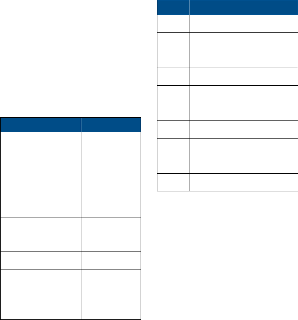
Additional Relevant Documents
The following documents are required if the corresponding
units are included in your system. These can be downloaded
from the Corning portal.
Document Name Part Number
RIU Product Family (RIU-4,
RIU-IM, and RIU-Lite) User
Manual
709C007703 Rev.
A00/CMA-139-AEN
RIU-12 User Manual 709C011602 Rev.
A00/CMA-334-AEN
FT350 Installation Guide
(includes OCH information) CMA-208-AEN
System Controller User
Manual (SC-450 v7.4 and
higher)
CMA-456-AEN
IFB Quick Installation Sheet —
Corning® Optical Network
Evolution (ONE™) Solutions
System Installation User
Manual (includes HEU/IHU
information)
CMA-490-AEN
List of Acronyms
Term Meaning
BTS Base transceiver station
BTSC Base transceiver station conditioner
DL
Downlink
GX Greater-power unit
HEU Headend unit
IFB Interface box
IHU Integrated headend unit
OCH Optical central hub
RIU Radio interface unit
UL Uplink

Corning Optical Communications User Manual | CMA-601-AEN | Page 6
TABLE OF CONTENTS
1 Introduction
1.1 Key Features and Capabilities ................................................... 7
1.2 System Description ....................................................................... 8
1.2.1 GX Dual-Band with Corning® Optical Network
Evolution (ONE™) Solution ............................................. 8
1.2.2 GX Interface Box (IFB) to ONE Headend .................. 10
1.2.3 GX Deployed with MA1K/MA2K Platform ............... 10
1.3 System Monitoring and Management ................................ 12
1.4 GX Dual-Band Interfaces ........................................................... 13
1.5 IFB Interfaces ................................................................................. 15
2 Installation Guidelines
2.1 Site Considerations ..................................................................... 17
2.1.1 Installation Location ....................................................... 17
2.1.2 Environmental ................................................................... 17
2.1.3 Powering .............................................................................. 17
2.1.4 Grounding Requirement ............................................... 17
2.1.5 Cable Routing .................................................................... 17
2.1.6 Manual Handling ............................................................. 17
2.2 Installation Requirements ........................................................ 17
2.3 Fiber Optic Rules .......................................................................... 18
3 System Installation
3.1 Selecting GX Dual-Band Mounting Location ..................... 19
3.2 Unpacking and Inspection ........................................................ 19
3.3 Additional Required Tools ........................................................ 21
3.4 Required Headend Connections for Deployments with
Corning® Optical Network Evolution (ONE™)
Solution ........................................................................................... 21
3.4.1 HEU/IHU-to-IFB Connections ...................................... 21
3.4.2 IFB-to-OCH Connections ................................................ 22
3.4.3 Management Connections ........................................... 22
3.5 Outdoor Concrete Wall-Mountable Installation.............. 23
3.6 Additional Installation Options .............................................. 23
3.6.1 Indoor Wall-Mountable Installation ......................... 23
3.6.2 Wooden Pole-Mountable Installation...................... 25
3.7 GX Connections ............................................................................29
3.7.1 Grounding Connections ................................................29
3.7.2 Fiber Connections ............................................................29
3.7.3 RF Connections ..................................................................31
3.7.4 Power Connections ......................................................... 32
3.7.4.1 AC Models ....................................................... 32
3.7.4.2 DC Models ....................................................... 32
3.7.5 External Alarm Connections ........................................ 33
3.7.6 System Alarm Pin-Out Description ........................... 34
3.8 Verifying Normal Operation .................................................... 34
4 Appendices
4.1 Appendix A: System Specifications ....................................... 35
4.2 Appendix B: Ordering Information ....................................... 38
Corning Optical Communications User Manual | CMA-586-AEN | Page 7
1
1
INTRODUCTION
GX products offer scalable, cost-effective 40 W (46 dBm)
high-power remote outdoor coverage solutions for Corning
distributed antenna systems (DAS).
GX remotes compliment both the MA1000/MA2000 platform
and the Corning® optical network evolution (ONE™) solution,
sharing a common equipment headend and element
management system (EMS) with the other system remotes.
GX is a fiber-fed, dual-band, multioperator remote designed to
complement lower power, standard remotes. GX can also be
installed as a dedicated solution for new sites, providing
complete RF coverage in large open indoor, tunnel, and
adjacent outdoor spaces.
Using low-loss fiber optic cabling, GX remote units can
distribute multiple BTS signal sources for 2.3 GHz and 2.5 GHz
TDD to multiple remote locations between 2 to 15 km from the
headend to remotes. GX efficiently supports all operator
modulations with linear MCPA (multicarrier power amplifier)
up to 40 W.
GX remotes offer high RF power coverage capabilities with
compact design for added spaces savings and
weather-resistant enclosures to fit various site needs..
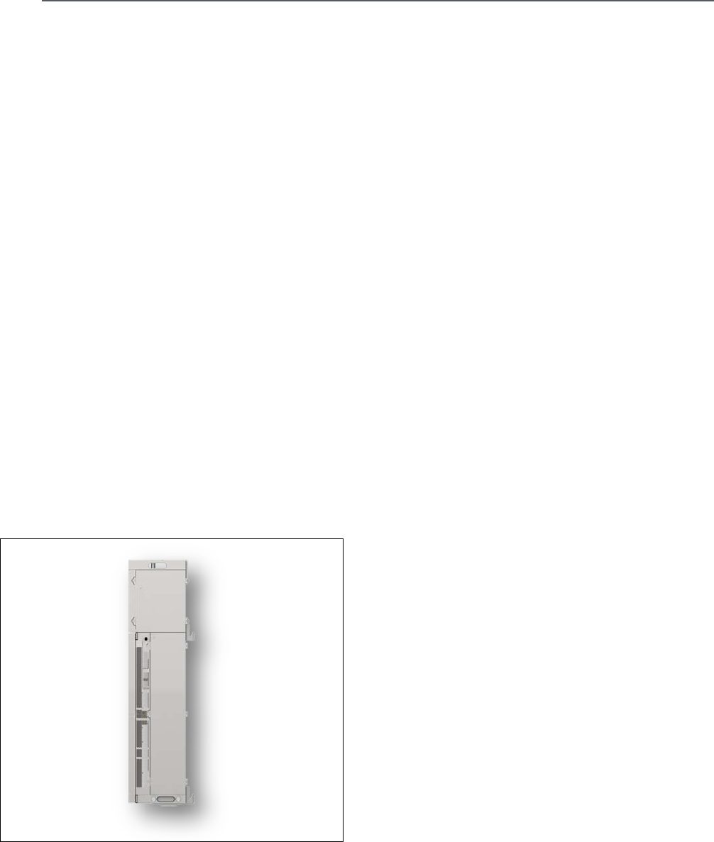
GX Dual-Band Remote | Figure 1.1
1.1 Key Features and Capabilities
Multi-frequency/multiservice RF transport
platform:
•
Accommodates LTE technology
•
Two bands per enclosure
Cost-effective high power
Optimizes and reduces the number of antennas required to
cover open outdoor areas by offering 46 dBm composite power
per frequency band
Operator-grade operation
Advanced signal handling, RF filtering, and management
ensures operator-grade performance
SISO/MIMO support
Model dependent units supporting either SISO or MIMO
configurations
Unique, space-saving, non-obtrusive design
Blends into the environment and avoids costly tower builds
outdoors when covering campus scenarios, parking lots,
tunnels, and indoor-adjacent outdoor spaces
Designed to withstand harsh environments
Fully sealed remote unit (RU) enclosure ensures superior
performance in harsh environments and worry-free electronics
maintenance. Compliant to NEBS OSP Class 4 rated standard
Management and control
Alarm forward to NOC or standard EMS via SNMP,
software-controlled output power, and optical link auto gain
control
Corning Optical Communications User Manual | CMA-601-AEN | Page 8
1.2 System Description
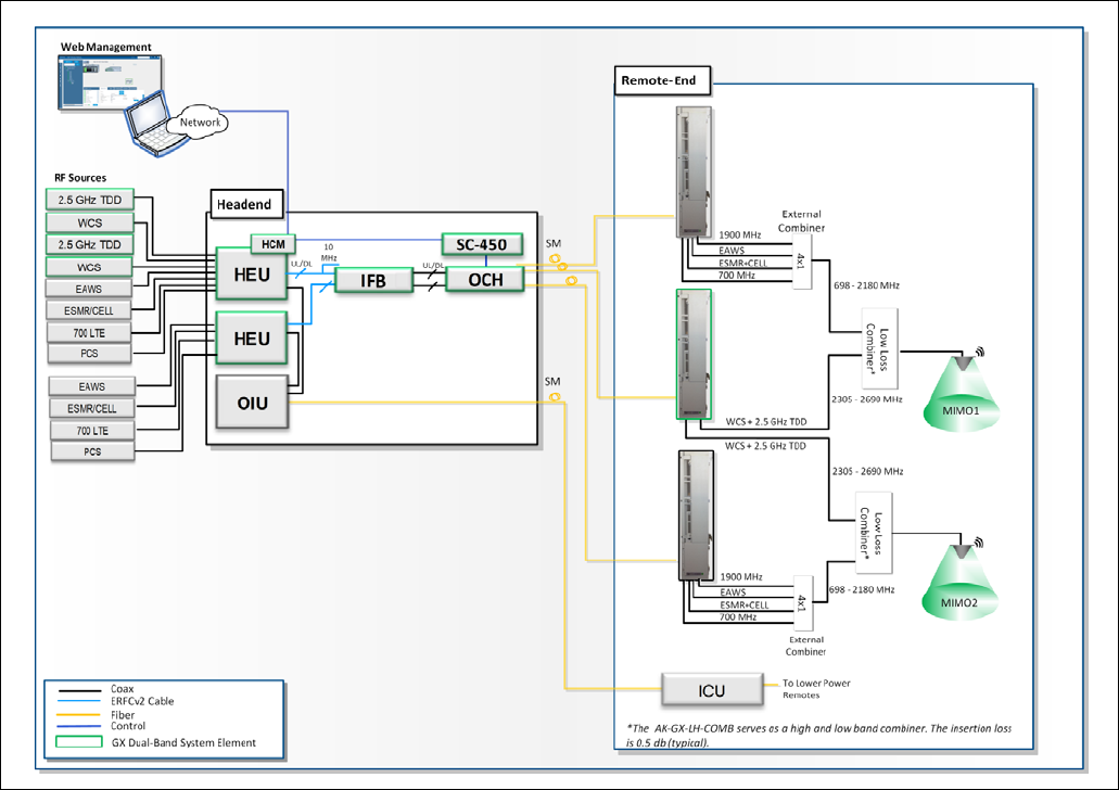
1.2.1 GX Dual-Band with Corning® Optical
Network Evolution (ONE™) Solution
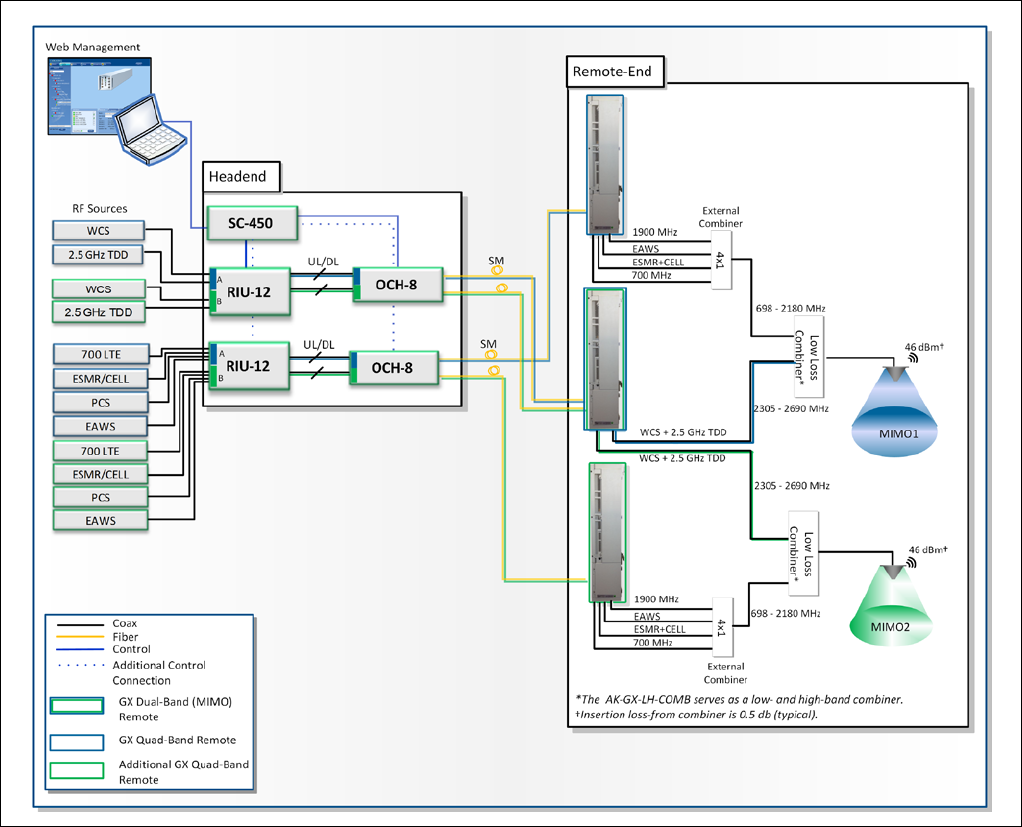
Figure 1.2 illustrates a scenario including the dual-band GX
MIMO remote supporting the WCS and 2.5 GHz TDD bands and
two quad-band GX remote units each supporting ESMR/CELL,
PCS, 700 LTE, and EAWS deployed with the Corning
®
optical
network evolution (ONE
™
) solution.
The MIMO1 and MIMO2 RF signals, received from the BTS, are
conditioned by the headend unit (HEU), ensuring a constant RF
level. The conditioned MIMO1 and MIMO2 signals are then
transferred via the interface box* (IFB) and routed through the
optical central hub (OCH)
†
optical modules. For the TDD band,
an integrated IF clock module (pilot), installed in the IFB enables
transmitting the converged wideband RF/IF and pilot signals
through the interface box to the OCH. The OCH converts the RF
signal to an optical signal for transport over low-loss fiber
cabling to/from multiple GX remotes, where they are converted
to high-level RF signals. The GX includes an internal combiner
so that both WCS and 2.5 GHz TDD bands services are
transmitted via a single output port (SISO) or two for MIMO.
An external low-loss combiner is used to combine the
dual-band GX with the quad-band GX to support six bands
services on a single output port.
The GX remotes (and OCH) are managed and controlled via the
headend control module (HCM)
‡
installed in the headend
chassis, enabling local and remote management and providing
single-source, centralized common headend controls of all
installed elements.
*Each interface box supports connections to up to two HEUs or integrated
headend units (IHUs) via ERFCv2 cables.
†RF connections between the interface box and the OCH are performed using
QMA-to-QMA cables (accessory kit part number: AK-RIU4-OCH-CABLES).
‡In deployments with the ONE solution, GX remotes require an SC-450 interfacing
between the OCH and HCM for management capabilities.
Notes:
•
Only extended radio interface modules (RIMe) support
GX-E17E85P19L70-40-AC and GX-E17E85P19L70-40-DC. See
ordering information in this document for relevant part
numbers.
•
The dual-band GX with WCS and 2.5 GHz TDD support is
supported by SC-450 v7.6 and higher and ONE
v3.3 and higher.
Corning Optical Communications User Manual | CMA-601-AEN | Page 9
Example of GX Dual-Band with Quad-Band Remotes in Corning® Optical Network Evolution (ONE™) Deployment | Figure 1.2
Corning Optical Communications User Manual | CMA-601-AEN | Page 10
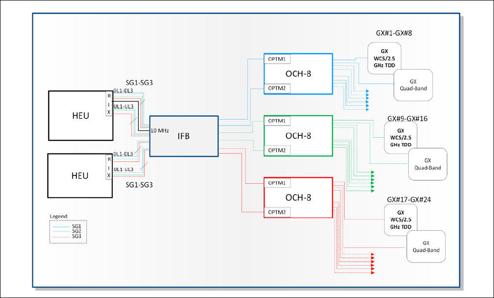
1.2.2 GX Interface Box (IFB) to ONE
Headend
The IFB is a combiner/splitter interface box which supports
connections to two HEUs, combines the RF services and routes
them through optical central hub (OCH) modules towards the
GX remotes.
The IFB includes an integrated intermediate frequency (IF) clock
module for generating a 2970 MHz pilot signal required for
synchronizing the TDD band.
The IFB enables deploying a GX high-power WCS/2.5 GHz TDD
(dual-band) remote alongside a GX quad-band remote where it
supports connections to two OCH optical modules per service
group (i.e., three OCH-8 or six OCH-4 units).
Block Diagram of IFB System Description | Figure 1.3
1.2.3 GX Deployed with MA1K/MA2K
Platform
Figure 1.4 illustrates a GX dual-band remote MIMO scenario
deployed with an MA1000/2000 headend alongside two GX
quad-band remotes providing MIMO coverage for the
CELL/ESMR, PCS, EAWS, and 700 LTE bands..
Note: GX quad-band models GX-E17E85P19L70-40-AC and
GX-E17E85P19L70-40-DC do not support coexistence with other GX
models. The quad-band services must be routed through separate
RF paths (i.e., different RIU-12 sector and optical module).
The MIMO1 and MIMO2 services are conditioned via two
independent sectors in the RIU-12 units, ensuring a constant RF
level for each MIMO stream. The conditioned MIMO1 and
MIMO2 signals are routed through separate optical modules in
the OCH. Each optical module converts the RF signal to an
optical signal for transport over low-loss fiber cabling to/from
connected GX remote, where they are converted to high-level
RF signals.
The GX dual-band remote includes an internal combiner so that
both WCS and 2.5 GHz TDD bands services are transmitted via a
single output port (SISO) or two for MIMO. In addition, an
external low-loss combiner is used to combine the dual-band
GX with the quad-band GX to support six bands services on a
single output port.
Corning Optical Communications User Manual | CMA-601-AEN | Page 11
Example of GX Dual-Band alongside GX Quad-Band Remotes in an MA2K System Deployment | Figure 1.4
Corning Optical Communications User Manual | CMA-601-AEN | Page 12
1.3 System Monitoring and
Management
The GX dual-band remote unit is centrally managed via the
SC-450 (v7.5 and higher) in MA1K/MA2K solutions and via the
headend control module (HCM v3.2 and higher) when deployed
with Corning® optical network evolution (ONE™) solutions*.
*In Corning optical network evolution (ONE) solution deployments, the SC-450 is
also required for the GX management.
The GX remote management connection is performed via the
optical central hub (OCH) to which it is physically connected.
The OCH is connected directly to the SC-450 controller so that a
single management connection enables management and
monitoring capabilities for the GX and host OCH
.
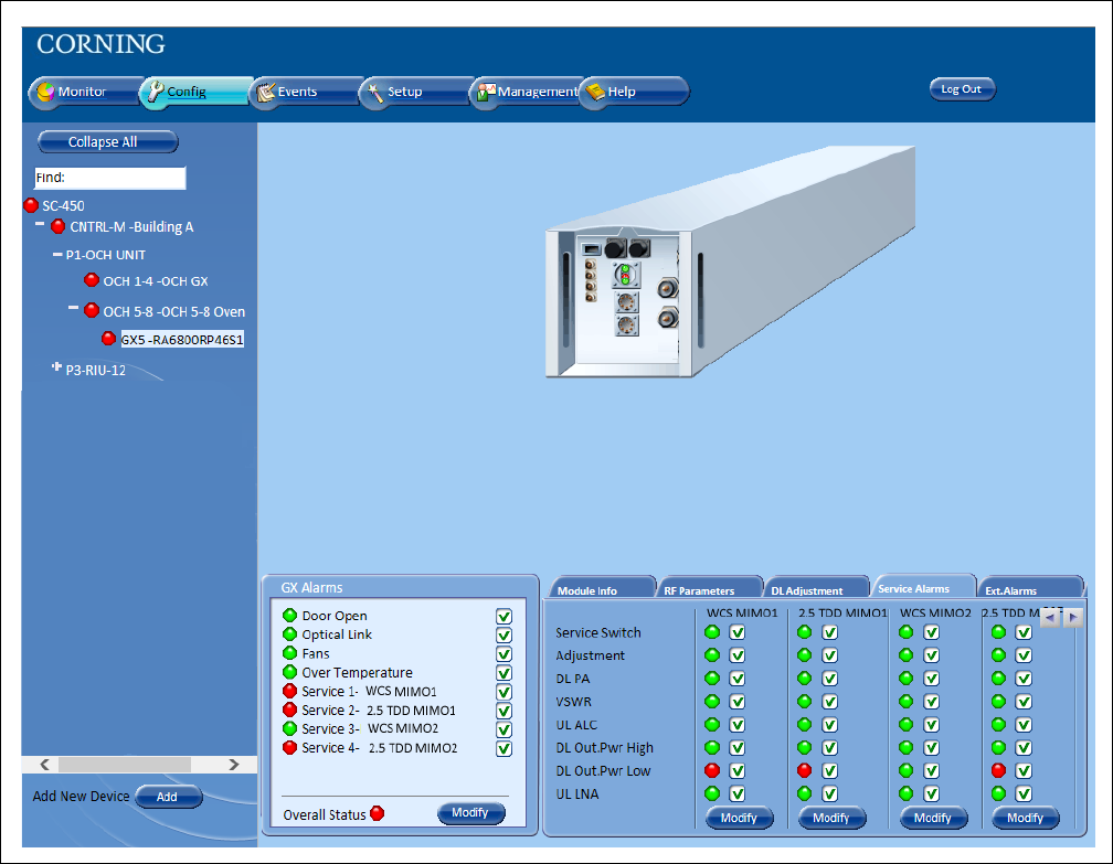
Figure 1.5 and Figure 1.6 show examples of GX management
screens in the SC-450 and HCM management web GUI
applications.
Example of GX Dual-Band SC-450 Configuration Tab | Figure 1.5
Corning Optical Communications User Manual | CMA-601-AEN | Page 13
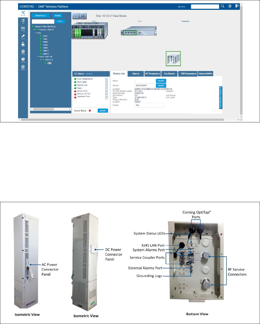
Example of GX Dual-Band HCM Device Configuration Tab | Figure 1.6
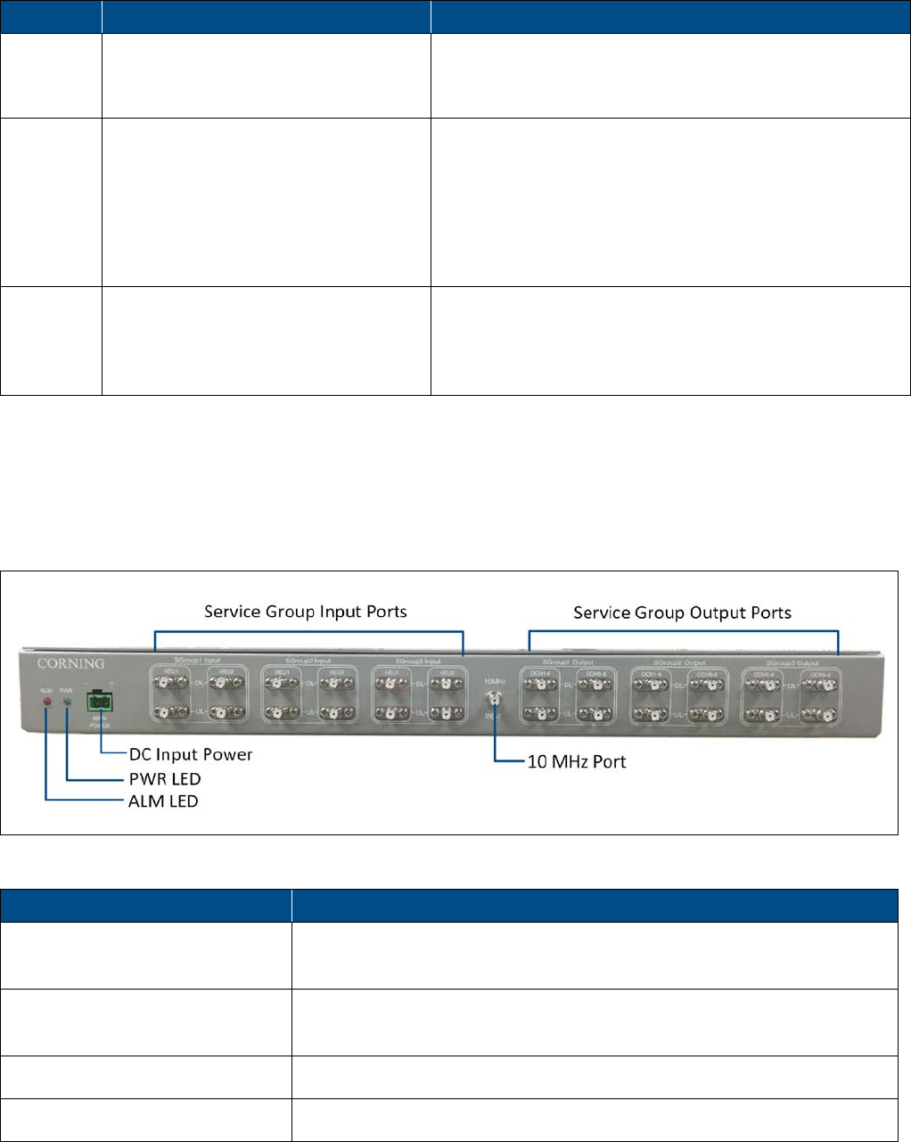
1.4 GX Dual-Band Interfaces
All of the GX interfaces (except for the power connector) are
located externally on the underside of the unit (facing down
when unit is mounted). The unit interfaces include the RF,
ground, optical link, and external alarms connections. The
power connector (AC/DC) is located on the side panel. See
Figure 1.7.
Example of GX Dual-Band Remote Interfaces | Figure 1.7

Corning Optical Communications User Manual | CMA-601-AEN | Page 14
Table 1.1 and Table 2.2 provide descriptions of the GX dual-band interfaces and LEDs.
Interface Description
Service Connectors Duplexed RF DIN female output connector to antennas (or external combiner);
Both 2.3 GHz (WCS) and 2.5 GHz service bands are distributed through a single
antenna output port
One connector for SISO models
Two connectors for MIMO models
OP Corning OptiTap® fiber optic waterproof connector – connects to OCH using
Corning OptiTap to SC APC cable (ordered separately). One connector for SISO
models and two for MIMO.
IMPORTANT!
OptiTap pull-out force ranges from a few lbs to 50+ lbs with the
dust cap or connector installed. This prevents damages caused to the DAS unit.
Power Connector (side panel) Power feed option is model dependent (AC/DC). Refer to Appendix A for detailed
power specifications
Note: AC models include power cable. Only provided power cable is to be used for power
connection.
Grounding Lugs Two grounding screws — accessed from side panel; double lugs with 6 gauge
wire
LAN RJ45 connector for local connection (i.e., debugging, troubleshooting)
EXT_ALM External Alarm pin-out connectors supporting four external alarm connections
SYS_ALM Pin-out connector supporting up to three relay alarms used for connecting the GX
dual-band to a network or modem and relaying the status of the GX alarms
WCS SISO CPL -50 dB Coupler port WCS SISO 50 dB coupling
TD25 SISO CPL -50 dB Coupler port 2.5 GHz TDD SISO 50 dB coupling
WCS MIMO CPL -50 dB
(for MIMO model)
Coupler port WCS MIMO 50 dB coupling
TD25 MIMO CPL -50 dB
(for MIMO model)
Coupler port 2.5 GHz TDD MIMO 50 dB coupling
GX Dual-Band Interface Descriptions | Table 1.1
Corning Optical Communications User Manual | CMA-601-AEN | Page 15
LED Status Description
RUN Blinking green Normal status, power on
Off Alarm status
ALM Steady red General alarm
Blinking red (two second blinking) Synchronization alarm
Blinking red (one second blinking) Optical attenuation alarm
Off Normal status
COMM. Blinking green — blinks on each command
received by the GX
Normal communication
Off Communication fault
GX Dual-Band LED Description | Table 1.2
1.5 IFB Interfaces
The IFB is a combiner/splitter interface box which supports
connections to two HEUs, combines the RF services, and routes
them through optical central hub (OCH) modules (two per
service group) towards the GX remotes. All interfaces are on the
front panel.
IFB Interfaces | Figure 1.8
Interface Description
SGroup Input 1/2/3 12 QMA input ports (six UL and six DL) — used for IFB connections to two HEUs;
HEU1 and HEU2 input connections for three service groups
SGroup Output 1/2/3 12 QMA output ports (six UL and six DL) — used for IFB connections to OCHs;
connections to two OCH optical modules per service group
10 MHz Input One QMA input port — 10 MHz reference signal
Main Power DC input – two pin plug; power input — -40 to -48 VDC

Corning Optical Communications User Manual | CMA-601-AEN | Page 16
Interface Description
ALM (LED) Red — fault detected with TDD sync (unlocked)
PWR (LED) Green — input power OK
IFB Interface Descriptions | Table 1.3

Corning Optical Communications User Manual | CMA-601-AEN | Page 17
2
2
INSTALLATION GUIDELINES
This chapter provides the general guidelines for installing the
GX dual-band remote and includes information such as site
considerations and installation requirements.
2.1 Site Considerations
•
The distance between the GX service antenna and the
coverage area should correspond to line of sight (LOS)
requirements for maximum coverage area.
•
The maximum fiber path loss is 6 dB.
•
The system delay of the optical system must be taken into
consideration when there are neighboring BTS sites
overlapping in coverage.
•
In the MIMO scenario, one MIMO remote unit shall use two
pairs of optic fiber to ensure avoiding system delay.
2.1.1 Installation Location
Mounting surface shall be capable of supporting the weight of
the equipment.
In order to avoid electromagnetic interference, a proper
mounting location must be selected to minimize interference
from electromagnetic sources such as large electrical
equipment.
2.1.2 Environmental
Humidity has an adverse effect on the reliability of the
equipment. It is recommended to install the equipment in
locations having stable temperature and unrestricted airflow.
The installation location for the system should be well
ventilated. The equipment has been designed to operate at the
temperature range and humidity level as stated in the product
specifications at temperatures ranging from -40~70 degrees
Celsius and a relative humidity of maximum 95 percent.
2.1.3 Powering
•
The power supply unit provides power to all modules within
the equipment. Depending on the product variant, it is
recommended that the PSU operates on a dedicated AC
circuit breaker or fused circuit.
•
Pluggable equipment — the socket outlet should be installed
near the equipment and be accessible
2.1.4 Grounding Requirement
Verify that the equipment has been well grounded. This
includes GX dual-band unit, external combiner, antennas, and
all cables connected to the system. For GX grounding, use
provided copper wire grounding cable. Ensure lightning
protection for the antennas is properly grounded.
2.1.5 Cable Routing
Ensure all cables, e.g., power cable, feeder cable, optic fiber,
commissioning cable, connecting are properly routed (use drip
loops) and secured so that they are not damaged.
2.1.6 Manual Handling
During transportation and installation, take necessary handling
precautions to avoid potential physical injury to the installation
personnel and the equipment.
2.2 Installation Requirements
•
Working space available for installation and maintenance for
each mounting arrangement. Ensure unrestricted airflow.
•
Ensure grounding connector is within reach of the ground
wire.
•
Ensure a power source is within reach of the power cord and
the power source has sufficient capacity.
•
Where appropriate, ensure unused RF connectors are
terminated.
Corning Optical Communications User Manual | CMA-601-AEN | Page 18
•
Do not locate the equipment near large transformers or
motors that may cause electromagnetic interference.
•
Reduce signal loss in feeder cable by minimizing the length
and number of RF connections.
•
Ensure the equipment will be operated within the stated
environment (refer to datasheet).
•
Where appropriate, confirm availability of suitably
terminated grade of RF and optical fiber.
•
Observe handling of all cables to prevent damage.
2.3 Fiber Optic Rules
ATTENTION!
•
Please also refer to the laser safety section in the document
preface material.
•
Fiber optic cables require proper handling. Do not stretch,
puncture, or crush the fiber cable(s) with staples, heavy
equipment, doors, etc.
•
Always maintain the minimum bend-radius specified by the
cable manufacturer. The minimum bend radius is usually ten
times the cable's outer diameter. In the case of single optical
fiber that is not in a cable, the minimum bending radius to be
observed is 30 mm.
•
Wavelength division multiplexing (WDM) units require
single-mode fiber.
•
Use minimum splicing/connectors to achieve minimum
losses on the fibers.
•
Use precaution while installing, bending, or connecting fiber
optic cables.
•
Use an optical power meter and optical time domain
reflectometer (OTDR) for checking the fiber optic cables.
•
Make sure the environment is clean while
connecting/splicing fiber optic cables.
•
All fiber optic connections should be cleaned prior to
attaching to termination points using a dry cleaning device
(e.g., Cletop or equivalent).
•
Fiber connector protective caps should be installed on all
non-terminated fibers and removed just before they are
terminated.
•
Check the fiber optic connections.
Corning Optical Communications User Manual | CMA-601-AEN | Page 19
3
3
SYSTEM INSTALLATION
This chapter describes the installation procedure for the GX
dual-band remote unit.
3.1 Selecting GX Dual-Band
Mounting Location
Select the mounting location (wall/pole):
•
General surroundings
•
Ventilated and easy-to-reach area
•
Proximity to the antenna in order to minimize cable loss
For installations with GX external multiplexer — take into
consideration that the unit must be mounted adjacent to the
GX RF interfaces to facilitate the connections (DIN-DIN cables =
1.2 m).
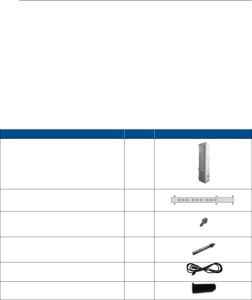
3.2 Unpacking and Inspection
Unpack and inspect the cartons as follows:
1. Open the shipping carton and carefully unpack each unit
from the protective packing material.
2. Please verify that the items listed in Table 3.1 are included
in your package (image size is not proportional) and check
for signs of external damage. If there is any damage, call
your Corning service representative.
Item Quantity
GX Dual-Band Remote Unit
1
Mounting Bracket (used for both pole and wall
installations)
1
M8 Nuts, Spring Washers 8 mm diameter, Plain Washers
8 mm diameter – used for securing remote unit when
hung on bracket protrusions
2
(per item)
Masonry Bolt (set) M10x110 – used for wall-mountable
installations
6
Power Supply Cable (AC) – for AC models 1
Power Cable Tube Gasket (DC) – for DC models 2
GX Dual-Band Package Items | Table 3.1
Corning Optical Communications User Manual | CMA-601-AEN | Page 20
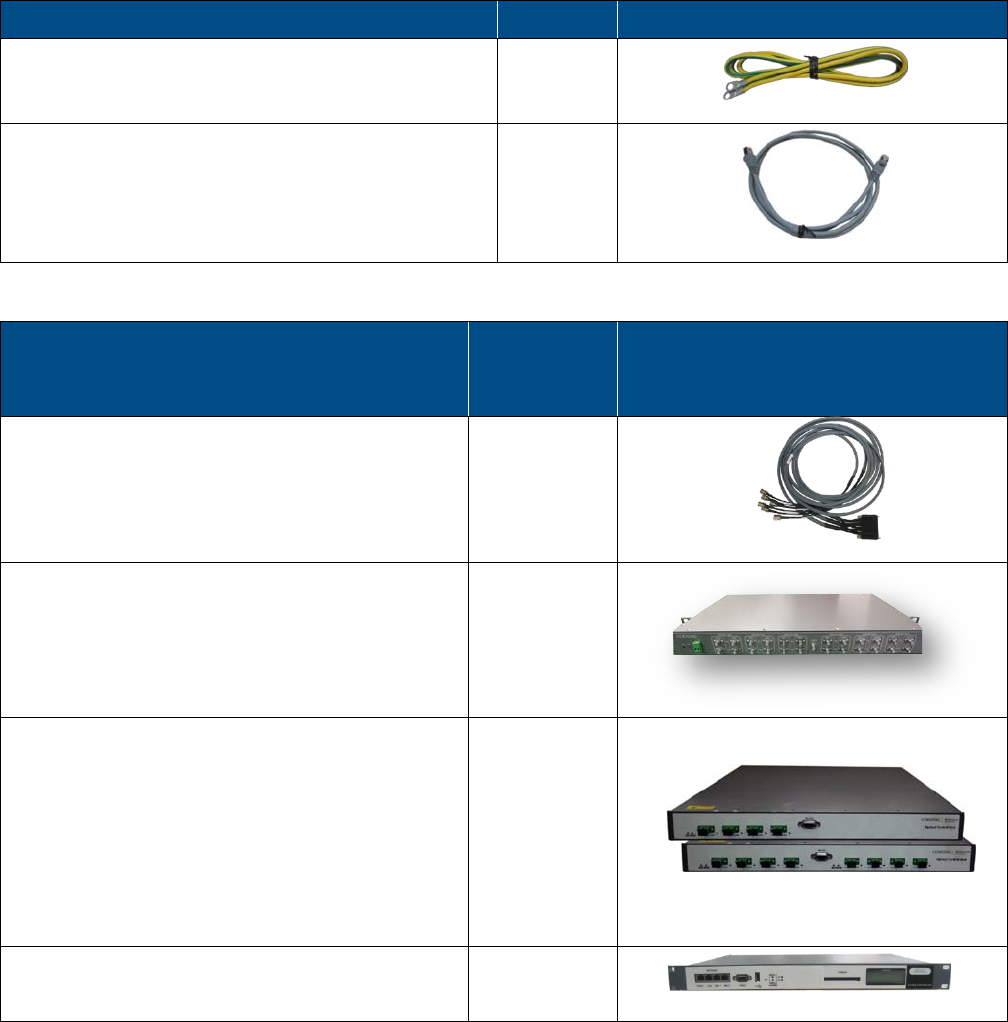
Item Quantity
Copper Grounding Wire (2 m) 1
RJ45 Ethernet Communication Cable 1
GX Dual-Band Package Items | Table 3.1 (continued)
Additional items required (and ordered separately)
for installations with Corning® Optical Network
Evolution (ONE™) Solution
Quantity
ERFCv2-OCH – RF Cables used for interfacing between
headend (i.e., HEU/IHU) extender module and the
interface box (IFB)
1
AK-ONE-HE-GX-INTBOX — Combiner/Splitter used for
interface between the headend unit and the OCH
1
OCH-4-WDM (top) – 4-Port Optical Central Hub
supporting up to four SISO remotes; wavelength
division multiplexing technology; single-mode fiber
OCH-8-WDM (bottom) – 8-Port Optical Central Hub
supporting up to eight SISO remotes or four MIMO
remotes; wavelength division multiplexing
technology; single-mode fiber
1
SC-450 – System Controller used for management of
GX and OCH
1
Required Items for GX Dual-Band in Installations with Corning® Optical Network Evolution (ONE™) Solution | Table 3.2
Corning Optical Communications User Manual | CMA-601-AEN | Page 21
Additional items required (and ordered separately)
for installations with MA1000/MA2000
deployment including RIU
Quantity
AK-RIU4-OCH-CABLES – RIU-4 Cable Accessory Kit
required for RIU-4-to-OCH connections, four
QMA-to-QMA R/A cables; Length = 1 m
1 -
AK-RIU12-OCH-CABLES – RIU-12 Cable Accessory Kit
including four RF QMA/QMA R/A cables used for
connections between RIU-12 and OCHs; Length = 1 m
1 -
Required Items for GX Dual-Band in Installations with MA1K/MA2K | Table 3.3
3.3 Additional Required Tools
•
Electric drill (12 mm diameter head for drilling holes for wall
mount)
•
Spanner (0.31-in for tightening GX M8 nuts)
•
For pole-mountable installations – the GX bracket supports
wooden pole mounting via a dedicated GX accessory kit
(ordered separately): AK-GX-QUAD-BRKT-WDPOLE
3.4 Required Headend
Connections for Deployments
with Corning® Optical Network
Evolution (ONE™) Solution
Important!
Each headend unit (HEU) supports up to eight GX remotes.
The following additional elements are required (ordered
separately):
•
Interface box — AK-ONE-HE-GX-INTBOX; used to combine
the RF services from two HEUs/IHUs and required for
synchronizing the TDD band (includes IF clock module for
generating a 2970 MHz pilot signal)
•
Optical central hub — OCH-4-WDM or OCH-8-WDM;
installed in 19-in communication rack with HEU
•
ERFCv2-OCH cable
•
SC-450 — installed in 19-in communication rack with the
HEU and OCH
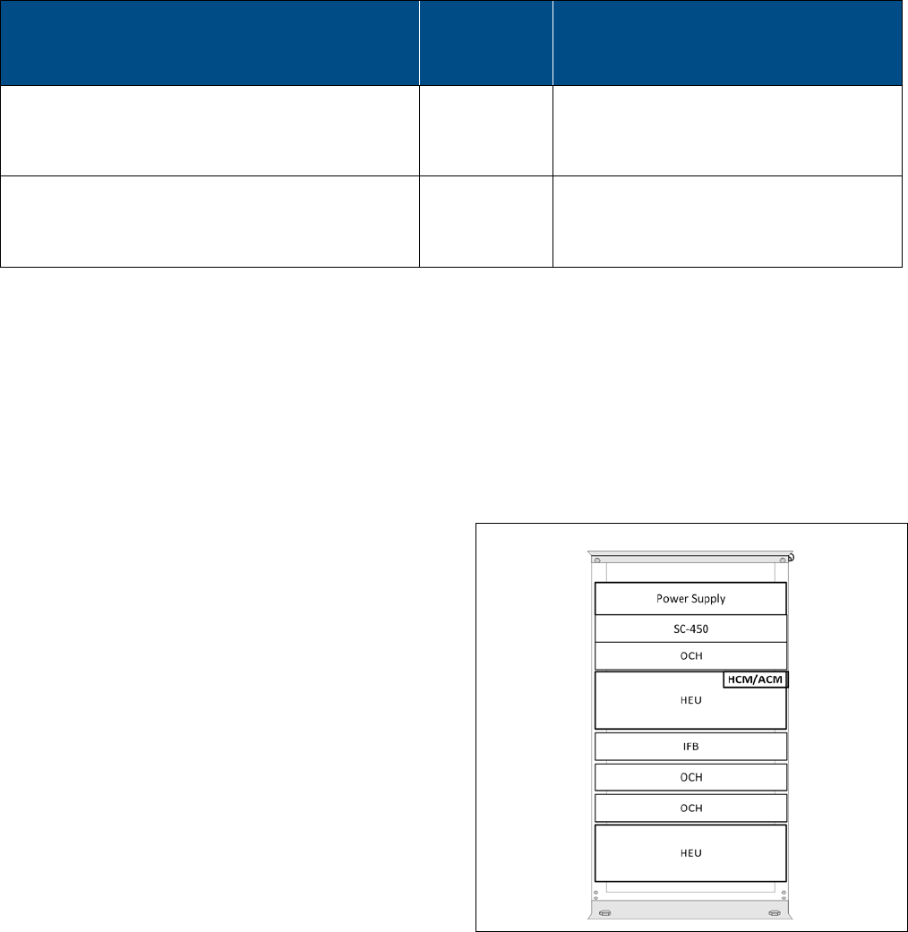
Notes:
•
Refer to the quick installation sheets provided with the HEU,
IFB, OCH, and SC-450 for instructions on how to install the
units.
•
Refer to Figure 3.6 for an example of where to install the IFB,
OCH, and SC-450 units in the communication rack with the
HEU in order to facilitate the cable connections.
Example of Rack Configuration with HEU | Figure 3.1
3.4.1 HEU/IHU-to-IFB Connections
Refer to Figure 3.2 and connect the HEU(s) to the IFB using the
ERFCv2-OCH cable as follows:
Note: Each ERFCv2-OCH cable supports UL/DL connections to up to
three service group input connections and one 10 MHz reference
clock connection.
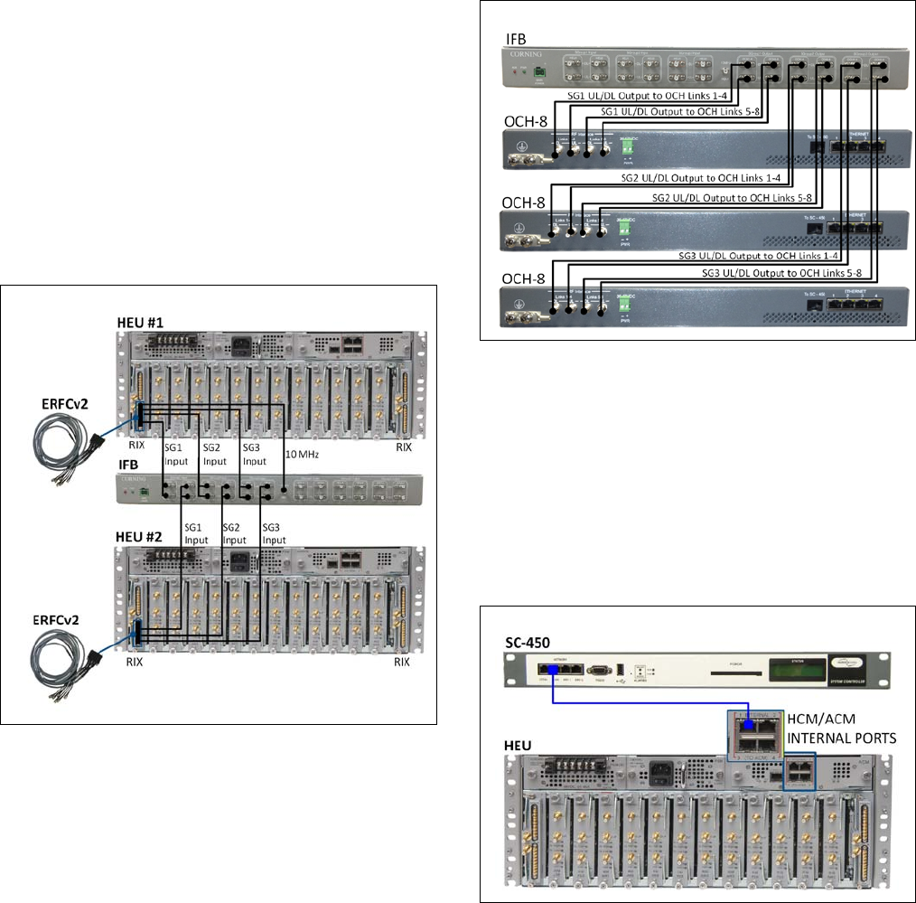
Corning Optical Communications User Manual | CMA-601-AEN | Page 22
1. Connect the 9-pin connector side of the ERFCv2-OCH cable
to an available HEU/IHU RIX port and secure the connector
in place.
2. UL/DL QMA connections — connect a pair of UL/DL QMA
cables to each of the IFB UL/DL service group input ports
(i.e., SG1, SG2, and SG3).
3. Connect the single QMA connection cable to the IFB 10
MHz QMA port.
4. Perform Steps 1-2 above for second HEU if installed.
Note: Only one 10 MHz clock reference connection to the IFB is
required.
Example of Connections between IFB and Two HEUs via ERFCv2
Cables | Figure 3.2
3.4.2 IFB-to-OCH Connections
The IFB output connections to the OCH are performed using
QMA/QMA cables (not provided with unit). Corning accessory
kits including appropriate cables can be ordered separately (see
Table 3.3).
Each IFB supports two optical modules (i.e., one OCH-8 or two
OCH-4 units) per service group.
Refer to Figure 3.3 and connect the IFB to the OCH as follows:
UL/DL QMA connections — connect a pair of QMA/QMA cables
from each of the service group UL and DL output ports to the
OCH optical module UL and DL link ports. IFB supports
connections to two optical modules per service group.
Connections Between IFB and Three OCH-8 Units | Figure 3.3
3.4.3 Management Connections
Connect the SC-450 front panel “LAN” port to any one of the
control module’s (HCM/ACM) four “INTERNAL” ports using the
RJ45 CAT 5 Ethernet cable, as shown in Figure 3.4.
GX management capabilities are attained through the OCH
connections to the SC-450 controller.
HCM-to-SC-450 Management Connection | Figure 3.4
Corning Optical Communications User Manual | CMA-601-AEN | Page 23
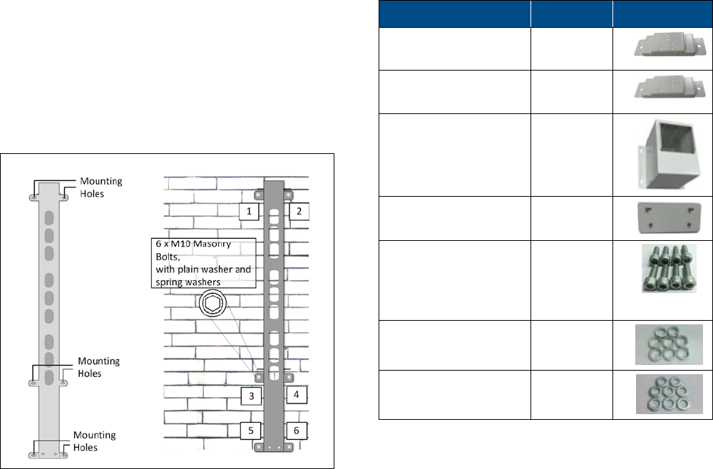
3.5 Outdoor Concrete
Wall-Mountable Installation
Note: The instructions provided in this section are for solid brick and
concrete walls only.
1. Using the mounting bracket top and bottom mounting
holes as a guide (see Figure 3.5), measure and mark the
location for drilling the (supplied) M10 masonry bolts
(12 mm dia) in the wall (six per bracket).
2. Drill holes for the masonry bolts (using an electric drill with
a 12 mm diameter head).
3. Using six M10x110 masonry bolts per bracket – secure the
mounting brackets to the wall with the protruding
M8 nuts facing toward you
.
See Figure 3.5.
GX Bracket Wall-Mountable Option | Figure 3.5
3.6 Additional Installation Options
Additional mounting options are provided with separately
ordered accessory kits:
•
Indoor wall-mountable installation (section 3.6.1)
•
Wooden pole-mountable installation (section 3.6.2)
3.6.1 Indoor Wall-Mountable Installation
This section provides instructions on how to mount the GX
quad-band unit on indoor concrete walls using the
AK-GX-QUAD-BRKT-INDOOR accessory kit (ordered separately).
Note the following:
•
The GX indoor bracket accessory kit is designed for
installations on concrete walls only.
•
The GX unit is mounted with the connectors facing
UPWARDS (as opposed to all other installation types).
•
Weight: GX (per unit) = 147 lb (66 kg); Bracket = 28.7 lb (13 kg)
The accessory kit includes the following items:
Item Quantity
Top Wall Rack
(6 holes)
1
Bottom Wall Rack
(8 holes)
1
Mounting Ground
Support
1
Sideboard 2
M6×16 Hex Socket
Head Cap screws –
required for sideboard
assembly
8
Spring Washer 8
Plain Washer 8
Kit Items for GX Indoor Bracket | Table 3.4
Additional required tools
•
Electric screwdriver with hex bits
•
Electric drill with a 12 mm diameter head
•
Spanner (0.31-in for tightening GX M8 nuts)
To mount GX in Indoor Installation
1. Determine the installation location so that there is enough
free space for proper ventilation and maintenance access.
2. Referring to Figure 3.6, dismantle the mat and mounting
hooks from the GX by unscrewing the corresponding
M5x12 screws. Save those screws for the following step.
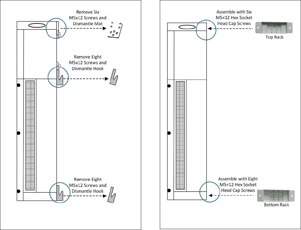
Corning Optical Communications User Manual | CMA-601-AEN | Page 24
Disassembling Mounting Hooks | Figure 3.6
3. Assemble the top wall rack on the GX using six M5×12 hex
socket head cap screws (previously removed and set aside).
4. Assemble the bottom wall rack on the GX using eight
M5×12 hex socket head cap screws (previously removed
and set aside).
Assembling Top and Bottom Racks | Figure 3.7
5. Place the GX unit on the mounting ground support with
the connectors facing upwards.
6. Secure the GX to the mounting ground support with the
two sideboards using eight M6x16 hex socket head cap
screws (provided with the accessory kit).
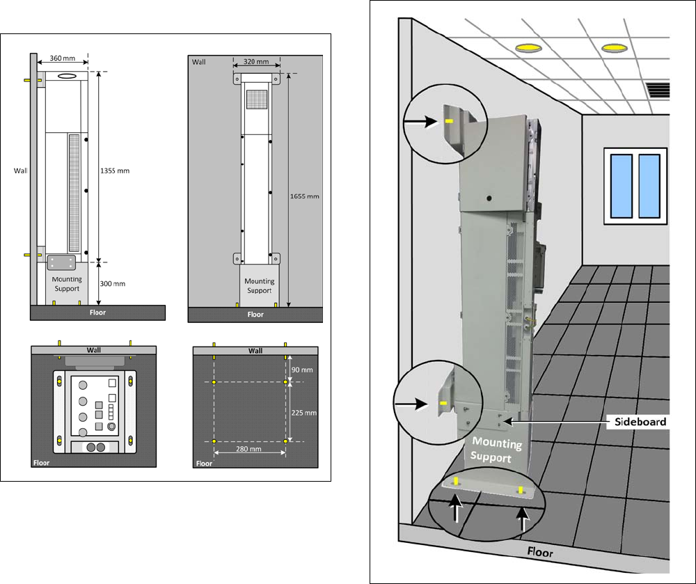
Corning Optical Communications User Manual | CMA-601-AEN | Page 25
Figure 3.8 provides an overview of the mounted GX unit.
Overview of Mounting Procedure | Figure 3.8
7. Position the GX and bracket assembly so that the
mounting brackets face the wall. Refer to “side view”
(top left image) and “front view” (top right image) shown
in Figure 3.8.
8. Using the screw holes as a template, drill the required
holes in the floor and wall (drill directly through the screw
holes). Refer to “Front View” (top-right image) and “Top
View” (bottom-left image) shown in Figure 3.8.
Note: Eight M10 masonry bolts are required (not provided).
9. Insert masonry M10 bolts into drilled holes and tighten.
Refer to Figure 3.9.
Location of Inserted Masonry Bolts | Figure 3.9
3.6.2 Wooden Pole-Mountable Installation
This section provides instructions on how to mount the GX
quad-band unit on wooden poles using the GX wooden-pole
bracket accessory kit (ordered separately).
Note the following:
•
This bracket is designed for installations on wooden poles
only.
•
Up to two GX units can be mounted on a single bracket, one
on each side.
•
Two people are required for mounting each GX unit onto
the bracket.
Corning Optical Communications User Manual | CMA-601-AEN | Page 26
•
The GX unit is mounted onto the pole with the connectors
facing downwards.
•
Weight: 147 lb (66 kg); Bracket = 30.9 lb (14 kg).
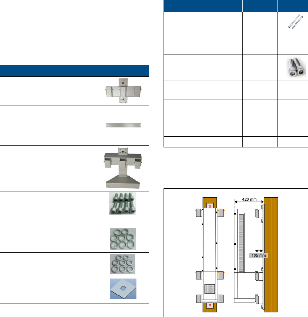
Package Contents
Check your package contents to verify that the items in the
packing list are included and that there are no signs of external
damage.
Item Quantity
Pole Bracket Top 1
Pole Bracket
Middle
1
Pole Bracket
Bottom
1
M6×16 Hex Socket
Head Cap Screw
(Bracket Assembly)
8
Spring Washer 8
Plain Washer 8
5/8-in Self-Tapping
Screws
(Wood Assembly)
4
GX Wooden Pole-Mountable Bracket Package Contents | Table 3.5
Additional required items (not included)
Item Quantity
5/8-in Screws and Nuts for
wooden pole assembly.
Screws must meet
requirement for related
installation environment.
4
M8×30 Screws for GX
assembly, included in GX
package
2
Electric Screwdriver with
the proper heads
1 -
Electric Drill with
appropriate head
1 -
Spanner (0.31-in for
tightening GX M8 nuts)
1 -
Hex Key 1 -
Additional Required Items | Table 3.6
Figure 3.10 and Figure 3.11 show an overview of a single-mount
and dual-mount GX installation.
Pole-Mountable GX – Single Mount | Figure 3.10
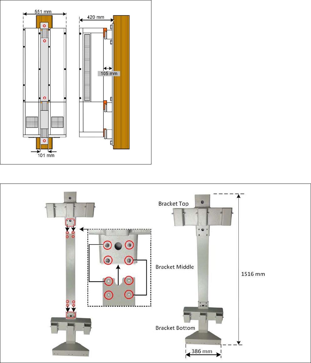
Corning Optical Communications User Manual | CMA-601-AEN | Page 27
Pole-Mountable GX – Dual Mount | Figure 3.11
To mount a GX unit on a wooden pole
1. Using the eight M6x16 hex socket screws and the relevant
washers, assemble the three parts of the pole bracket as
shown in Figure 3.12.
Wooden Pole Bracket Assembly | Figure 3.12
Corning Optical Communications User Manual | CMA-601-AEN | Page 28
2. Select the appropriate location for the bracket according to
the following criteria:
•
General surroundings
•
Make sure that the bracket is installed high enough to ensure
convenient access to the GX connectors located on the
underside of the unit when mounted.
•
Ventilated and easy-to-reach area
•
Proximity to the antenna in order to minimize cable loss
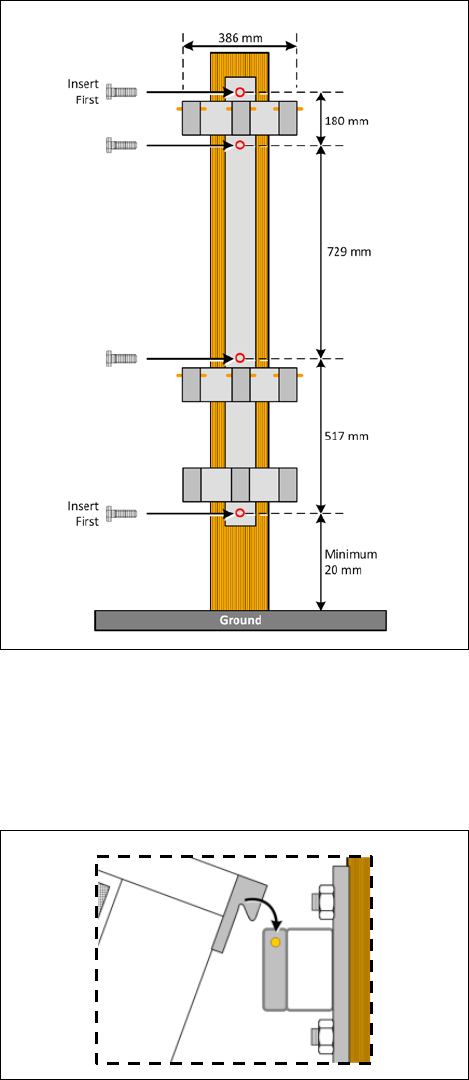
3. Referring to Figure 3.13, mount the wooden pole bracket
according to the following steps:
•
Drill four holes in the pole according to the distances shown
in Figure 20.
•
Position the bracket onto the wooden pole and screw in the
5/8-in screws (provided) into the top and bottom mounting
holes.
•
Screw in the two additional screws into the remaining middle
mounting holes and tighten.
Note: The distance between the bracket bottom screw and the
ground must be at least 20 mm.
Mounting the Bracket | Figure 3.13
4. Mount the GX unit onto the bracket: - referring to
Figure 3.14, hang the GX on the pins protruding from the
relevant top and center parts (depending on single or dual
installation) of the bracket.
Hooking GX onto Bracket | Figure 3.14
Note: For single GX unit installation – unit is mounted onto middle
of bracket (Figure 3.15); For Dual GX unit installations – units are
mounted on the sides of the bracket (Figure 3.16).
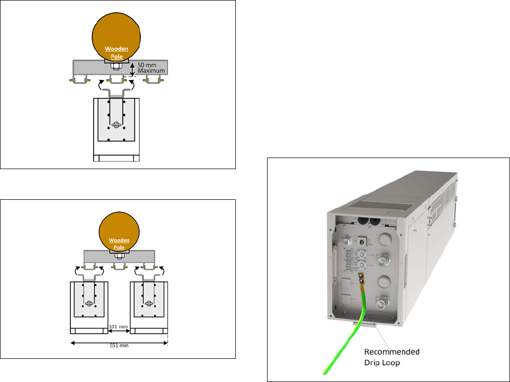
Corning Optical Communications User Manual | CMA-601-AEN | Page 29
Single-Mounted GX Unit | Figure 3.15
Dual-Mounted GX Units | Figure 3.16
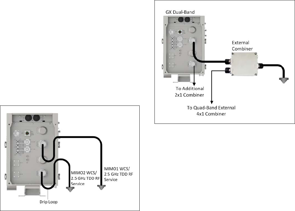
3.7 GX Connections
IMPORTANT! CABLE DRIP LOOPS RECOMMENDED.
It is highly recommended that every horizontal cable entry to
the equipment forms a 'U' before its entry to the equipment.
Water on the cable will drip down at the bottom of the loop
and will not accumulate at the equipment connectors.
3.7.1 Grounding Connections
WARNING!
This unit must always be grounded. Consult an
appropriate electrical inspection authority or an electrician if
you are uncertain that suitable grounding is available.
DO NOT
CONNECT POWER BEFORE GROUNDING!
Note: An internationally acceptable color code of the ground
connection wire is green/yellow.
To ground the GX unit
1. Connect the supplied copper wire (AWG #6) GND cable to
the GND connector and the equipment rack or building
earth.
2. Ground the GX unit by connecting the provided “earth
wire” of the power cord to the ground terminal of the AC
supply.
GX Grounding Connection | Figure 3.17
3.7.2 Fiber Connections
IMPORTANT!
OptiTap® pull-out force ranges from a few lbs to
50+ lbs with the dust cap or connector installed. This prevents
damages caused to the DAS unit.
Connect the GX OP
OptiTap port to one of the OCH front panel
“Link” ports (via F/O patch panel), using an OptiTap cable
assembly (ordered separately). MIMO units require two fiber
connections, where each one must be connected to a different
optical module.
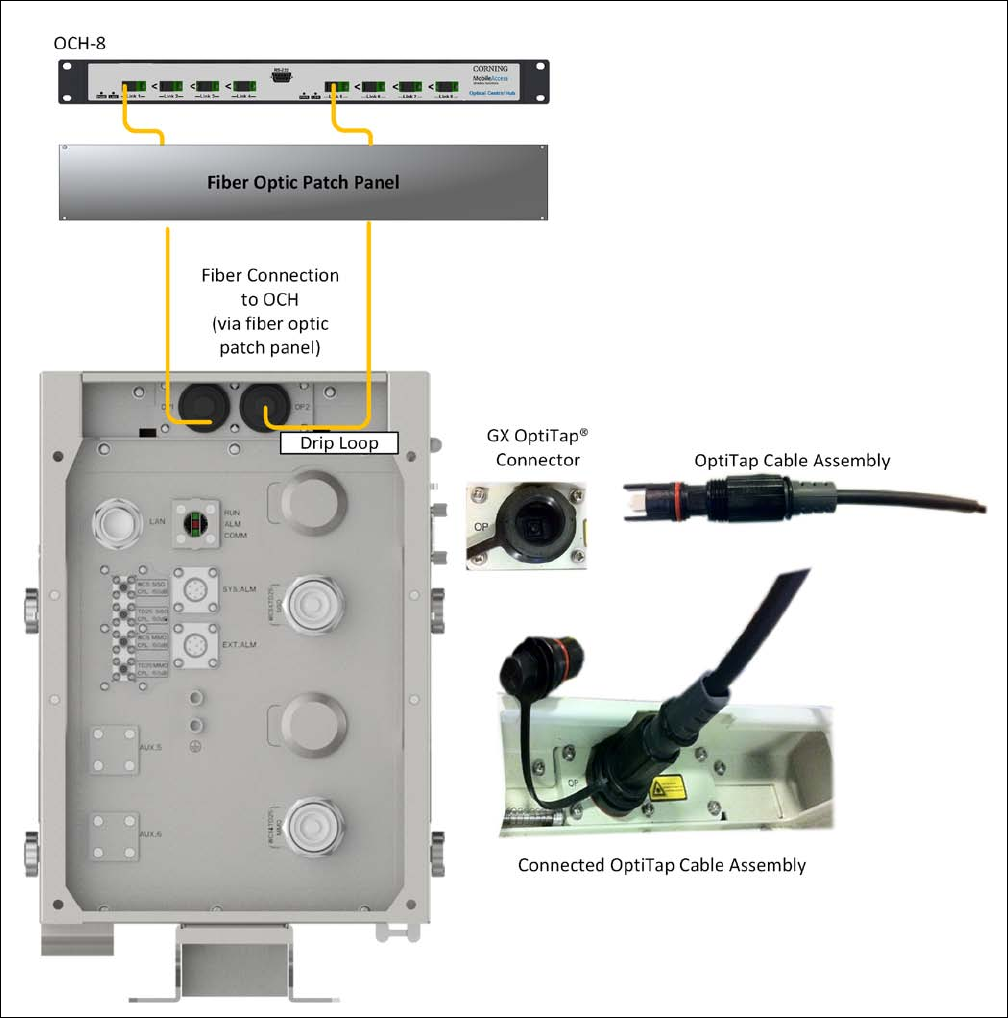
Corning Optical Communications User Manual | CMA-601-AEN | Page 30
GX Dual-Band (MIMO) Fiber Optic Connections | Figure 3.18
Corning Optical Communications User Manual | CMA-601-AEN | Page 31
3.7.3 RF Connections
CAUTION!
Any open RF port on GX or improper connection
between GX RF ports and combiner inputs, will damage GX
internal power amplifier after the equipment is powered on.
Make sure all connections are performed correctly before
powering.
Note: When deployed with GX quad-band (with EAWS) units, the GX
dual-band high-band RF services can be combined with the
quad-band low-band services using the dual-band combiner (P/N:
AK-GX-LH-COMB).
For direct connections to DAS antennas
1. Using the required coax cables, connect the GX RF port(s) to
the service antennas. One for SISO models and two for
MIMO models.
2. Ensure lightning protection for each antenna port.
3. Waterproof all RF ports (recommended drip loops).
4. Terminate any unused GX and RF ports.
Illustration of GX Dual-Band (MIMO) Direct RF Connection to DAS |
Figure 3.19
For connections via GX external low/high-band combiner:
1. Referring to Figure 3.20 and using the provided DIN-to-DIN
cables, connect the GX RF service antenna port to one of
the two external combiners input ports (Port1/Port2).
Note: MIMO models require to external combiners.
2. Connect the combiners’ 7/16 DIN output connector to the
DAS antenna.
Illustration of GX and Dual-Band External Combiner Connections |
Figure 3.20
Corning Optical Communications User Manual | CMA-601-AEN | Page 32
3.7.4 Power Connections
CAUTION!
Any open RF port on GX or improper connection
between GX RF ports and filter input ports will damage GX
internal power amplifier after the equipment is powered on.
Make sure all connections are performed correctly before
powering.
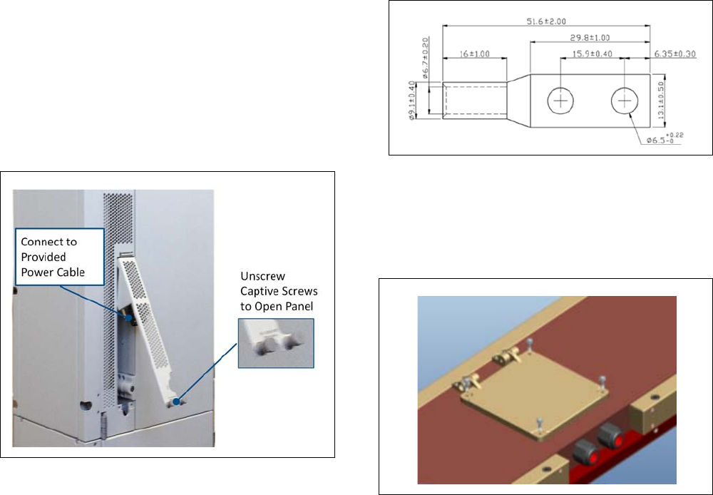
3.7.4.1 AC Models
To connect AC power
1. Unscrew the two screws of the side panel (shown in
Figure 3.21) and open to access the power connector
GX AC Model Power Connector | Figure 3.21
2. Connect the supplied power cable to the power supply
port:
•
Power input: VAC 100-240/47-63 Hz
•
Maximum power consumption: 1100 W
•
Maximum current consumption: 11 A maximum
3.7.4.2 DC Models
Verify the following before connecting DC power:
•
DC power supply is turned off
•
DC cable (not provided) meets the following requirements:
•
Supports required voltage and current specifications: -40
to -57 VDC and 27.5 A maximum
•
Cable diameter ranges between 7 and 14 mm
•
Cable lug specs (refer to Figure
3.22 for example of
compliant lug) :
-
Hole size: 1/4-in
-
Hole spacing: 5/8-in
Example of Compliant DC Cable Lug | Figure 3.22
To connect DC power
1. Open DC power chamber panel by loosening four M3
screws, as shown in Figure 3.23.
Opening DC Chamber Panel | Figure 3.23
2. Referring to Figure 3.24, remove retaining nut, insert DC
power cable through tubing gasket (provided), then
carefully route the power cable into the chamber (through
hole) and connect the lug to terminal (make sure right DC
polar is connected).
3. Tighten retaining nuts.
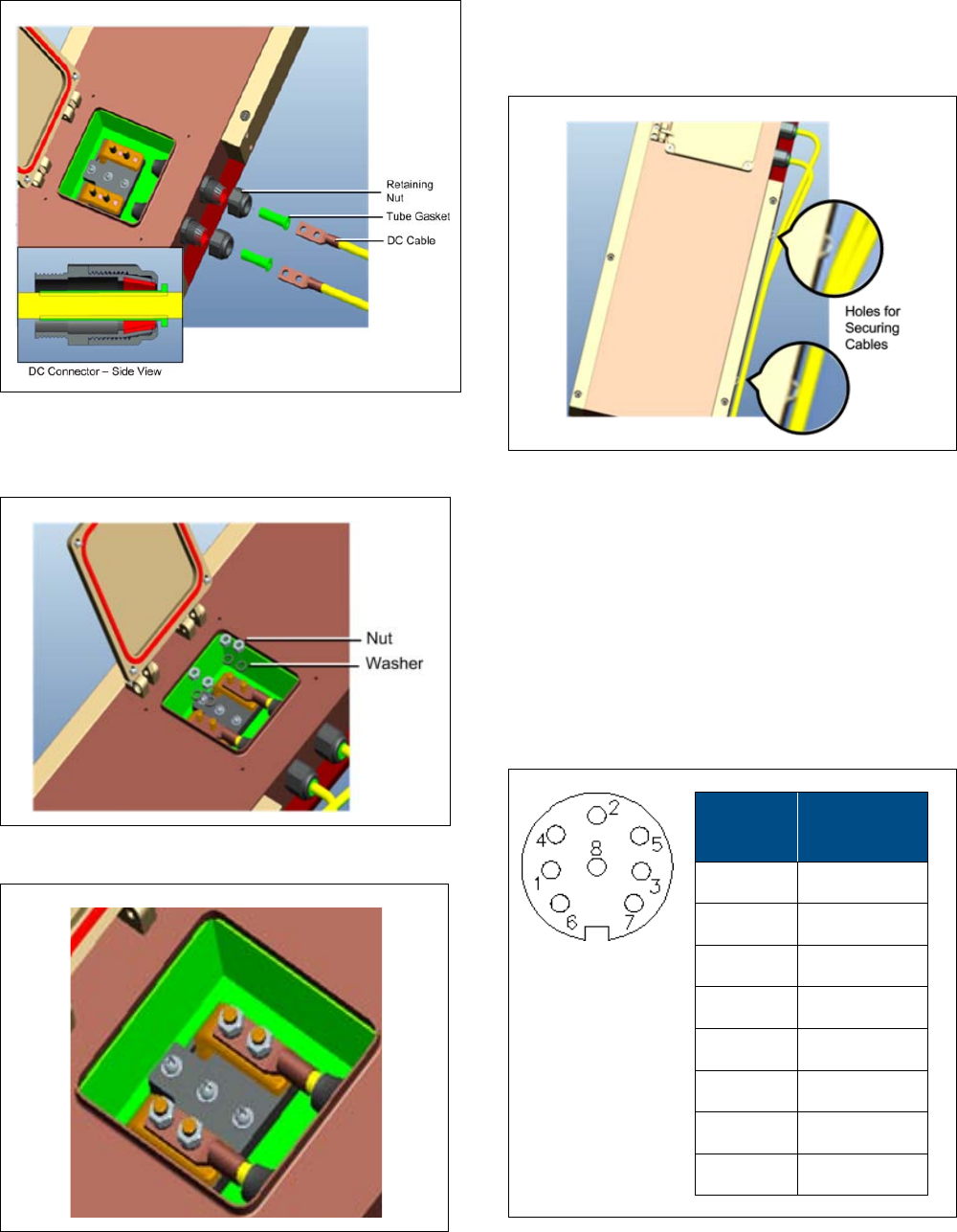
Corning Optical Communications User Manual | CMA-601-AEN | Page 33
Connecting Power Cord to Terminal | Figure 3.24
4. Referring to Figure 3.25, use nut to tighten lug to terminal.
Tightening Lug to Terminal | Figure 3.25
Securing Lug and Terminal | Figure 3.26
5. It is highly recommended to have power cords fixed or
tighten with an enclosure-type element. Additional holes
are left for that purpose. See Figure 3.33.
Fixed Power Cable | Figure 3.27
3.7.5 External Alarm Connections
The GX dual-band external alarm port supports up to four
dry-contact alarm connections from external sources (incoming
outputs). The alarms can be connected any time, before or after
the system is powered-on.
Note: After being connected, the external alarms must be enabled
from the web management application (see SC-450 user manual –
v7.5 and higher).
Pin
Number
Description
1 EXT_ALM1
2 EXT_COM1
3 EXT_ALM2
4 EXT_COM2
5 EXT ALM3
6 EXT_COM3
7 EXT ALM4
8 EXT_COM4
External Alarm Pin-Out Description | Table 3.7
Corning Optical Communications User Manual | CMA-601-AEN | Page 34
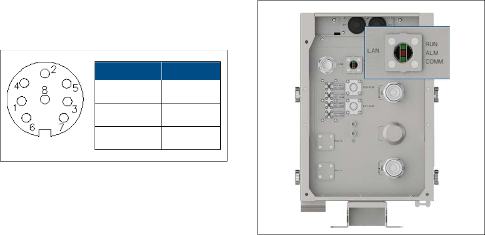
3.7.6 System Alarm Pin-Out Description
The GX dual-band system alarm pin-out connector supports
three relay alarm connections. GX dual-band status alarms can
be relayed via a network or modem connection.
Pin Number Description
1 EXT_OPEN
2 EXT_COM
3 EXT_CLOSE
x
System Alarm Pin-Out Description | Table 3.8
3.8 Verifying Normal Operation
Upon powering up the GX dual-band remote unit:
•
Confirm the fans are working after powering.
•
Refer to GX status LEDs (described in Section
1.4, Table 1.2)
and verify normal operation.
GX Dual-Band Status LEDs | Figure 3.28
Corning Optical Communications User Manual | CMA-601-AEN | Page 35
4
4
APPENDICES
4.1 Appendix A: System Specifications
RF Parameters
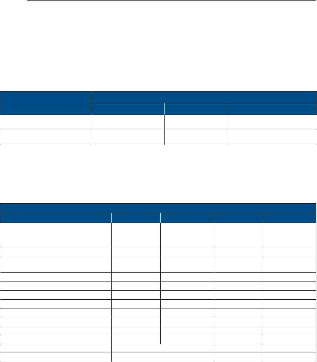
Supported services
Technologies Frequency Range
Service/Band Uplink Downlink
LTE WCS 2305-2315 2350-2360
LTE TDD 2.5 GHz 2496-2690 2496-2690
Supported Services | Table 4.1
RF Parameters per Service (40 W)
Notice: The manufacturer’s rated output power of this equipment is for the composite band or a single carrier operation. For situations when
multiple carrier signals are present, the rating for each carrier would have to be reduced by 10*Log(N), where N is the number of the
transmitted channels. The gain reduction for each carrier shall be done on the headend, and not by an attenuator at the output of the device.
LTE WCS LTE 2.5 GHz TDD
RF Parameters DL UL DL UL
Nominal Bandwidth (MHz) 10 10 60 MHz
Between 2496
to 2690
60 MHz
Between 2496 to
2690
Mean Output Power (dBm) 46 46
Maximum Output Power (dBm)
1 Carrier (Composite) 46 46
2 Carriers 43 43
4 Carriers 40 40
Nominal Passband Gain (dB) 66 (OCH to GX) 50 (GX to OCH) 66 (OCH to GX) 50 (GX to OCH)
Mean Gain (dB)
66 50 66 50
Gain Range (dB) 30 30 30 30
Maximum Pin (dBm)
at AGC Threshold -20 (at OCH) -54 -20 (at OCH) -54
Maximum Intermod Distortion (dBm) -13 -13
NF (dB) at Maximum Gain 5 5
VSWR 1.5:1 1.5:1
Gain Flatness/Ripple (dB)
+/- 2.0
Corning Optical Communications User Manual | CMA-601-AEN | Page 36
Coupling Specifications
Frequency (MHz) Typical Coupling* (dB)
WCS -50.0
2.5 GHz TDD -50.0
*
Depending on the band, the actual coupling value may slightly vary.
Optical Specifications
Parameter Value
Maximum Optical Budget 6 dBo
Optical Return Loss > 50 dB
Optical Loss per Mated-pair
Connectors
0.5 dB (maximum)
Optical Connector OptiTap
®
fiber optic waterproof connector
Optical Automatic Gain Control
Range
-2 to -10 dBm
Fiber Type Single-mode: 9/125 μm
Wavelength 1310 nm, 1550 nm + WDM
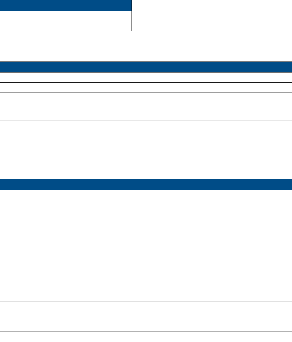
Physical Specifications
Parameter Value
Ports OptiTap fiber optic waterproof connector; One for SISO and two for MIMO
RF DIN duplexed female connectors; One for SISO and two for MIMO
Two 1/4-in grounding screws for AWG #18 GND cable
One RJ45 waterproof LAN connector
Power Dual-Band
SISO
Dual-Band
MIMO
AC: Input: VAC 100 - 240/47-63 Hz
Maximum power consumption: 750 W 1100 W
DC: Input: VDC (-40) to (-57)
Maximum power
consumption:
750 W 1100 W
Physical Characteristics Weight: 147 lb (66.6 kg)
Mounting: Wall-mountable or pole-mountable
Dimensions: 53.15 x 8.9 x 12.4 in (1350 x 226.06 x 314.96 mm)
Cooling Feature Active heat dissipation (fan)
Corning Optical Communications User Manual | CMA-601-AEN | Page 37
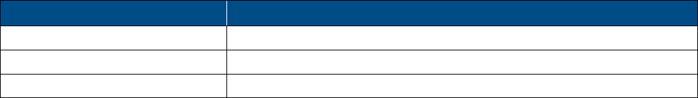
Environmental Specifications
Parameter Value
Operating Temperature -40 to +70°C (-40 to +158°F)
Humidity ≤ 95 percent
Enclosure NEBS OSP Class 4 rated (enclosure protected from elements and waterproofing)

Corning Optical Communications User Manual | CMA-601-AEN | Page 38
4.2 Appendix B: Ordering Information
Note: The information listed below is updated up to the publishing date. Refer to the GX 40 W dual-band datasheet (CMA-585-AEN) for the
most updated ordering information.
GX Dual-Band Remotes
Services Supported Part Number Description
WCS/2.5 GHz TDD MIMO GX-WCSM2500M-40 GX Dual-Service MIMO for WCS and 2.5
GHz TDD solution supporting 40 W output
for AC powering.
GX-WCSM2500M-40-DC GX Dual-Service MIMO for WCS and 2.5
GHz TDD solution supporting 40 W output
for DC powering.
WCS/2.5 GHz TDD SISO GX-WCSS2500S-40 GX Dual-Service SISO for WCS and 2.5 GHz
TDD solution supporting 40 W output for
AC powering.
GX-WCSS2500S-40-DC GX Dual-Service SISO for WCS and 2.5 GHz
TDD solution supporting 40 W output for
DC powering.
Optical Central Hub (OCH)
Part Number Description
OCH-4-WDM Optical Central Hub for SISO services, supporting four SISO remote units,
single-mode (WDM)
OCH-8-WDM Optical Central Hub for SISO or M
IMO services, supporting eight SISO or four
MIMO remote units, single-mode (WDM)
Extended Radio Interface Modules (RIMe)
Note: GX remotes deployed with the Corning® optical network evolution (ONE ™) solution are supported by extended radio interface modules
(RIMe) only.
Part Number Description
RIMe-25T Extended Radio Interface Module with support for the 2500 MHz TDD
band; RF Input: -11 to 37 dBm
RIMe-W23 Extended Radio Interface Module with support for the WCS 2300 MHz
band; RF Input: -11 to 37 dBm

Corning Optical Communications User Manual | CMA-601-AEN | Page 39
SC-450 Controller
Note: GX dual-band remotes require an SC-450 controller for management purposes also when deployed with the Corning® optical network
evolution (ONE™) solution.
Part Number Description
SC-450 System controller
Accessories
Part Number Description
AK-GX-LH-COMB GX Accessorized 2-to-1 External Diplexer for low- and high-band
ERFCv2-OCH Extender RF Cables from RIX to IFU
AK-ONE-HE-GX-INTBOX GX Accessories ONE™ Headend to GX interface box
AK-RIU4-OCH-CABLES Accessory Kit Cables for RIU-4 to OCH, four QMA to QMA R/A cables, 1 m
AK-GX-QUAD-PWR-CABLE GX AC Electrical Power Cable for US GX quad-band
AK-GX-QUAD-ELEC-ADP-AC AC Electrical Junction Adapter IP67 rated
AK-GX-QUAD-BRKT-INDOOR GX Accessory Kit including bracket for wooden pole-mountable option
AK-GX-QUAD-BRKT-WDPOLE GX Accessory Kit including bracket with ground support for indoor concrete
wall-mounting option
OptiTap® Cable Assemblies
Part Number Description
434401EB4R2005M-P OptiTap® to SC APC 5 m
434401EB4R2030M-P OptiTap to SC APC 30 m
434401EB4R2100M-P OptiTap to SC APC 100 m
434401UB4H3005M-P OptiTap to SC APC Cable Assembly, indoor/outdoor, riser-rated 5 m
434401UB4H3030M-P OptiTap to SC APC Cable Assembly, indoor/outdoor, riser-rated 30 m
434401UB4H3100M-P OptiTap to SC APC Cable Assembly, indoor/outdoor, riser-rated 100 m
OptiTap to SC APC cable
Note: The listed OptiTap cables are available on demand within a week of the order. Custom length cables require longer lead times. For more
information, contact your Corning account manager.

Notes:
Corning Optical Communications LLC
•
PO Box 489
•
Hickory, NC 28603-0489 USA
800-743-2675
•
FAX: 828-325-5060
•
International: +1-828-901-5000
•
www.corning.com/opcomm
Corning Optical Communications reserves the right to improve, enhance, and modify the features and specifications of Corning
Optical
Communications products without prior notification. A complete listing of the trademark
s of Corning Optical Communications is available at
www.corning.com/opcomm/trademarks. All other trademarks are the properties of their respective owners. Corning Optical Commun
ications
is ISO 9001 certified. © 2017 Corning Optical Communications. All rights reserved. CMA-601-AEN / October2017
P/N 709C021601 Rev A00