Corning Optical Communication GXC85L70A17-40 GX High Power DAS Remote Unit, Repeater User Manual MbileAccessHX 2W UM

Corning Optical Communication Wireless GX High Power DAS Remote Unit, Repeater MbileAccessHX 2W UM

OJFGXC85L70A17-40 User Manual Rev1
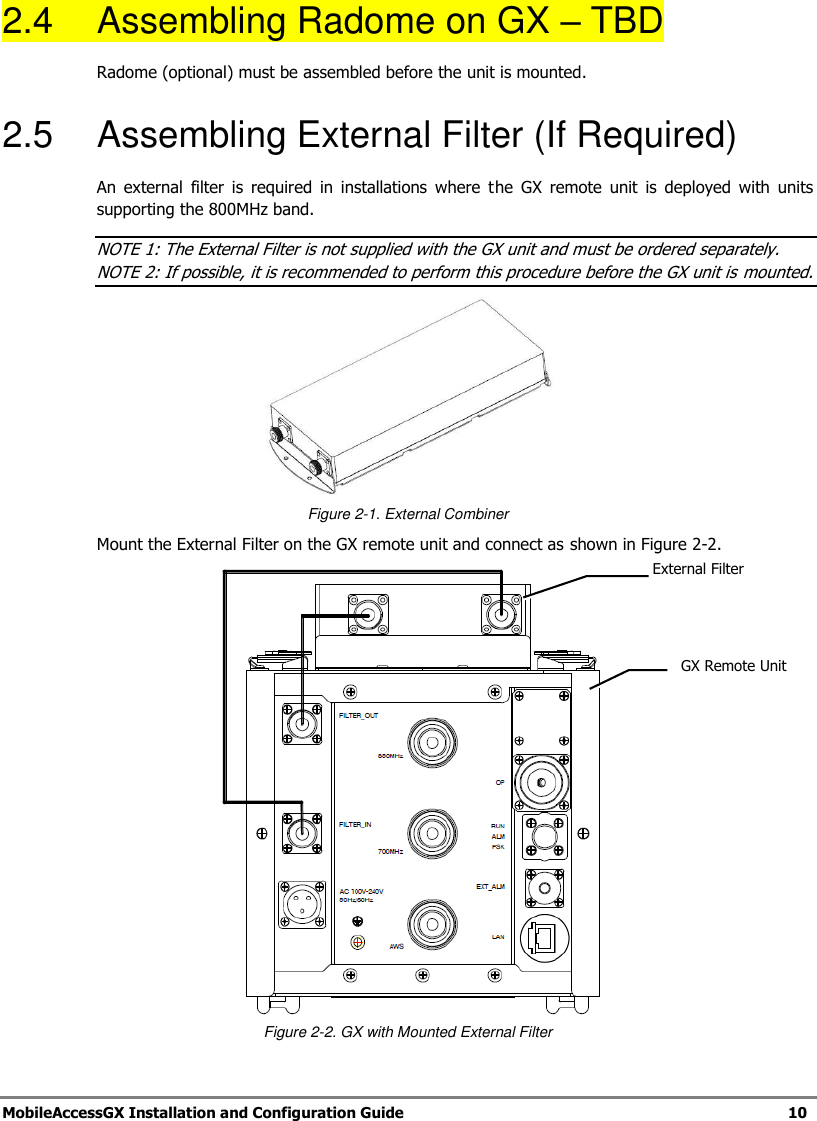
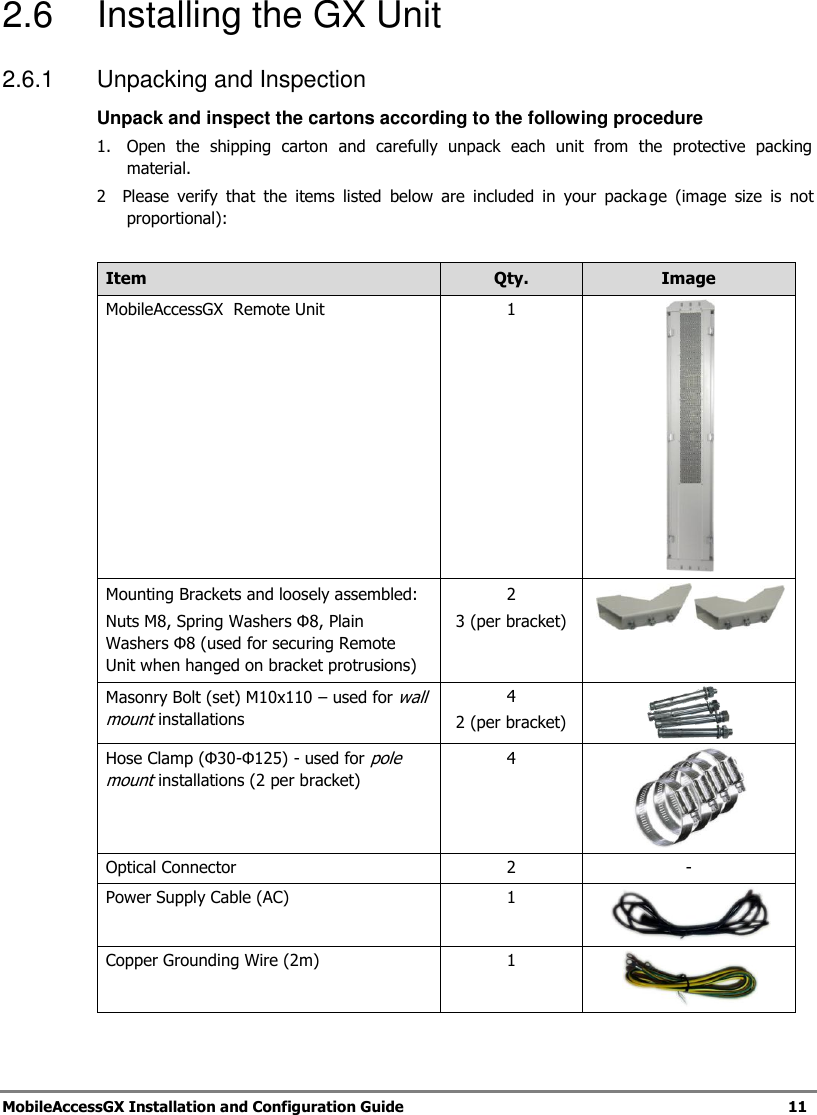
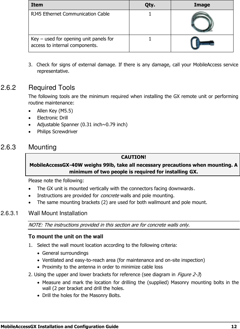
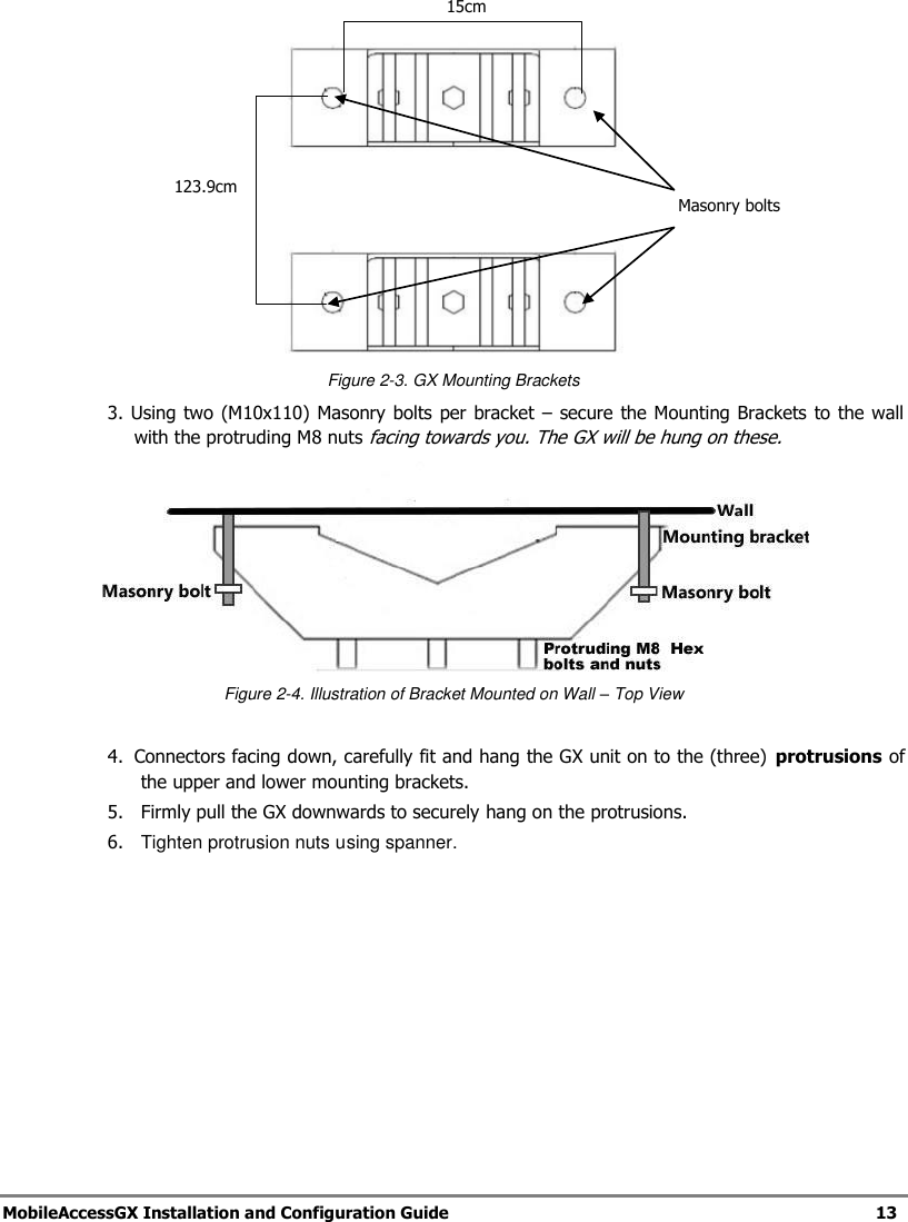
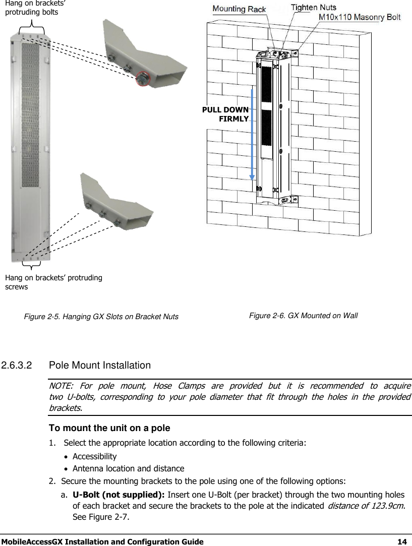
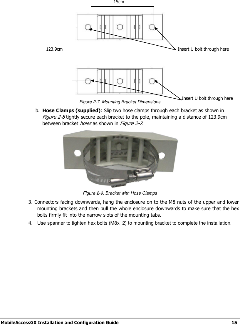
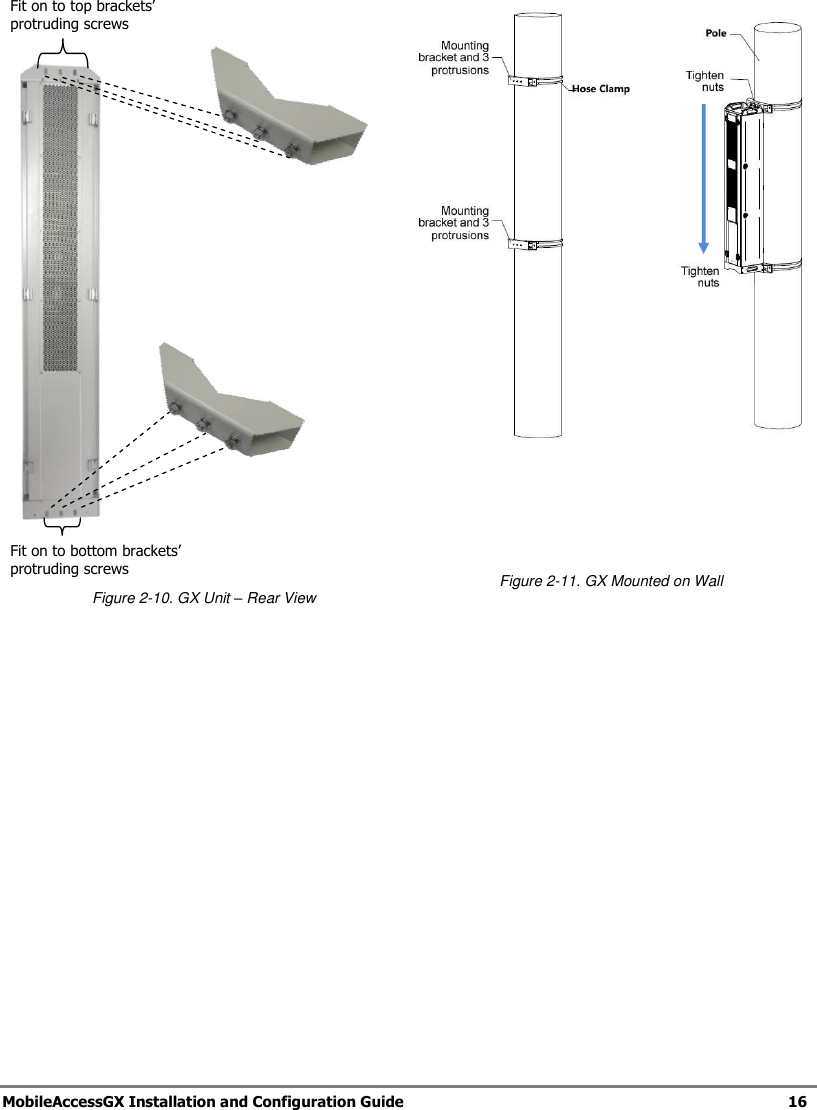
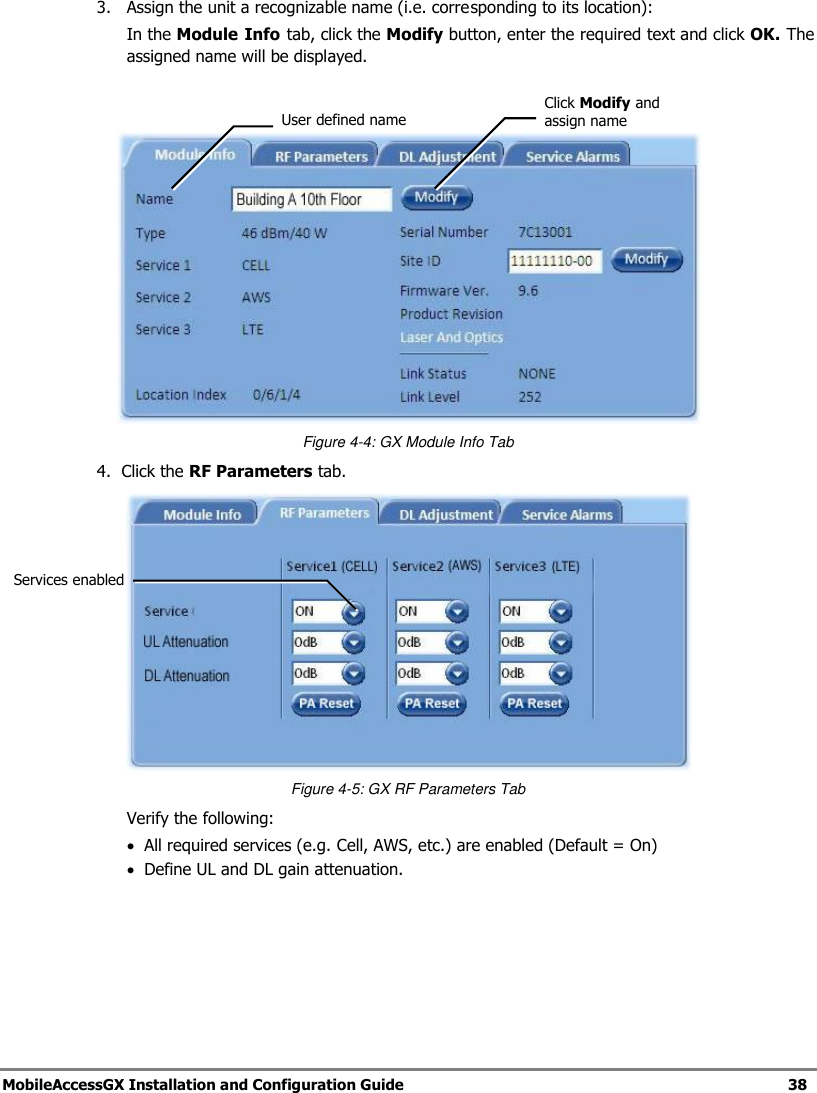
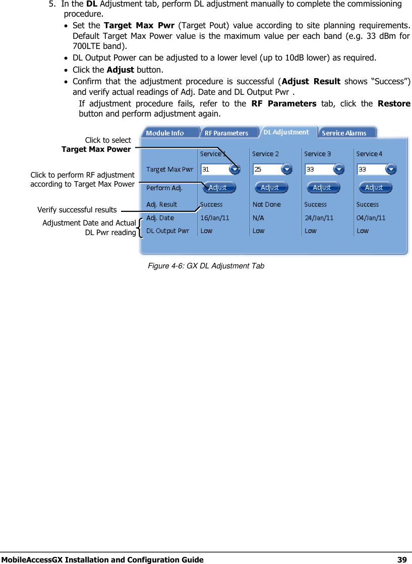
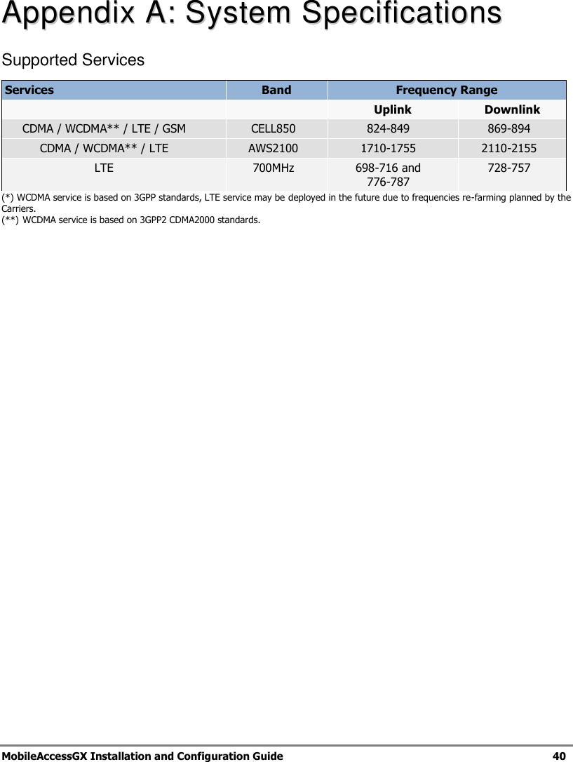
                                                 MobileAccessGX™ DAS System Installation and Configuration Guide P/N: 709C010701 REV: A0 Date: MAY, 2012
    Preface       MobileAccessGX Installation and Configuration Guide   II Corning MobileAccess 8391 Old Courthouse Road, Suite 300, Vienna, VA 22182 Tel: +1(866)436-9266, +1(703)848-0200 TAC: +1(800)787-1266, Fax: +1(703)848-0280 www.corning.com/mobileaccess     MobileAccessGX and MobileAccess are trademarks of Corning MobileAccess, Inc. Corning MobileAccess is a trademark of Corning Incorporated. Corning MobileAccess Inc. is a wholly-owned affiliate of Corning Incorporated.
    Preface       MobileAccessGX Installation and Configuration Guide   III PPrreeffaaccee  MMaatteerriiaall  ©  Copyright 2012, MobileAccess  All Rights Reserved.   This document may contain confidential and proprietary information of Corning MobileAccess, Inc. (“MobileAccess”) and may not be copied, transmitted, stored in a retrieval system or reproduced in any format or media, in whole or in part , without the prior written consent of MobileAccess. Information contained in this document supersedes any previous manuals, guides, specifications, data sheets or other information that may have been provided or made available to the user. This document is provided for informational purposes only, and Corning MobileAccess does not warrant or guarantee the accuracy, adequacy, quality, validity, completeness or suitability for any purpose of the information contained in this document. Corning MobileAccess reserves the right to make updates, improvements and enhancements to this document and the products to which it relates at any time without prior notice to the user. CORNING MOBILEACCESS MAKES NO WARRANTIES, EXPRESS OR IMPLIED, INCLUDING, WITHOUT LIMITATION, THOSE OF MERCHANTABILITY AND FITNESS FOR A PARTICULAR PURPOSE, WITH RESPECT TO THIS DOCUMENT OR ANY INFORMATION CONTAINED HEREIN.    Policy for Warrantee and Repair Corning MobileAccess tests and inspects all its products to verify their quality and reliability. Corning MobileAccess uses every reasonable precaution to ensure that each unit meets their declared specifications before shipment. Customers should advise their incoming inspection, assembly, and test personnel about the precautions required in handling and testing our products. Many of these precautions can be found in this manual. The products are covered by the following warranties: General Warranty Corning MobileAccess warrants to the original purchaser all standard products sold by Corning MobileAccess to be free of defects in material and workmanship for one (1) year from date of shipment from Corning MobileAccess. During the warranty period, MobileAccess will repair or replace any product that Corning  MobileAccess proves to be defective. This warranty does not apply to any product that has been subject to alteration, abuse, improper installation or application, accident, electrical or environmental over-stress, negligence in use, storage, transportation or handling. Specific Product Warranty Instructions All Corning MobileAccess products are warranted against defects in workmanship, materials and construction, and to no further extent. Any claim for repair or replacement of units found to be defective on incoming inspection by a  customer must be made within 30 days of receipt of shipment, or within 30 days of discovery of a defect within the warranty period. This warranty is the only warranty made by MobileAccess and is in lieu of all other warranties, expressed or implied. Corning MobileAccess sales agents or representatives are not authorized to make commitments on warranty returns.  Returns In the event that it is necessary to return any product against above warranty, the following procedure shall be followed:  1. Return authorization is to be received from MobileAccess prior to returning any unit. Advise  Corning MobileAccess of the model, serial number, and discrepancy. The unit may then be forwarded to Corning MobileAccess, transportation prepaid. Devices returned collect or without authorization may not be accepted. 2. Prior to repair, Corning MobileAccess will advise the customer of our test results and any charges for repairing customer-caused problems or out-of-warranty conditions etc.
    Preface       MobileAccessGX Installation and Configuration Guide   IV 3. Repaired products are warranted for the balance of the original warranty period, or at least 90 days from date of shipment. Limitations of Liabilities Corning MobileAccess's liability on any claim, of any kind, including negligence for any loss or damage arising from, connected with, or resulting from the purchase order, contract, quotation, or from the performance or breach thereof, or from the design, manufacture, sale, delivery, installation, inspection, operation or use of any equipment covered by  or furnished under this contact, shall in no case exceed the purchase price of the device which gives rise to the claim.  EXCEPT AS EXPRESSLY PROVIDED HEREIN, MOBILEACCESS MAKES NO WARRANTY, EXPRESSED OR IMPLIED, WITH RESPECT TO ANY GOODS, PARTS AND SERVICES PROVIDED IN CONNECTION WITH THIS AGREEMENT INCLUDING, BUT NOT LIMITED TO, THE IMPLIED WARRANTIES OF MERCHANTABILITY AND FITNESS FOR A PARTICULAR PURPOSE. MOBILEACCESS SHALL NOT BE LIABLE FOR ANY OTHER DAMAGE INCLUDING, BUT NOT LIMITED TO, INDIRECT , SPECIAL OR CONSEQUENTIAL DAMAGES ARISING OUT OF OR IN CONNECTION WITH FURNISHING OF GOODS, PARTS AND SERVICE HEREUNDER, OR THE PERFORMANCE, USE OF, OR INABILITY TO USE THE GOODS, PARTS AND SERVICE . Reporting Defects The units were inspected before shipment and found to be free of mechanical and electrical defects.   Examine the units for any damage that may have been caused in transit. If damage is discovered, file a claim with the freight carrier immediately. Notify Corning MobileAccess as soon as possible.  NOTE:   Keep all packing material until you have completed the inspection   RF Safety NOTE:   Keep all packing material until you have completed the inspection WARNING:   To comply with FCC RF exposure compliance requirements, antennas used for this product must be fixed mounted on indoor permanent structures, providing a separation distance of more than 300 cm from all persons during normal operation. WARNING: Antenna gain should not exceed 10 dBi. WARNING: Each individual antenna used for this transmitter must be installed to provide a separation distance greater than 300 cm or more from all persons and must not be co-located with any other antenna for meeting RF exposure requirements. WARNING: The design of the antenna installation needs to be implemented in such a way so as to ensure RF radiation safety levels and non-environmental pollution during operation.
    Preface       MobileAccessGX Installation and Configuration Guide   V Safety Instructions  Installation Safety Guidelines   Follow all safety regulations when installing the GX system  Only qualified personnel are authorized to install and maintain the GX system   The equipment is intended for installation in restricted access locations only RF Safety  WARNING! To comply with FCC RF exposure compliance requirements, antennas used for this product must be fixed mounted on indoor permanent structures, providing a separation greater than 300 cm from all persons during normal operation. 1. Each  individual  antenna  used  for  this  transmitter  must  be  installed  to provide a separation distance greater than 300 cm or more from all persons and  must  not  be  co-located  with  any  other  antenna  for  meeting  RF exposure requirements.  2. The design  of  the antenna installation  needs  to be implemented in such  a way  so  as  to  ensure  RF  radiation  safety  levels  and  non-environmental pollution during operation. Compliance with RF safety requirements:  Corning MobileAccess products have no inherent significant RF radiation.  The RF level on the  downlink is very low  at the downlink ports. Therefore,  there  is  no dangerous RF radiation when the antenna is not connected.   Laser Safety THE LASER APERTURES /OUTPUTS ARE THE GREEN SC/APC BULKHEAD ADAPTERS LOCATED ON THE FRONT PANEL OF THE EQUIPMENT. THE PRODUCT IS CLASS 1/HAZARD LEVEL 1 FIBER OPTIC PORTS OF THE MOBILEACCESS FT-350 EMIT INVISIBLE LASER RADIATION AT THE 1310/1550 NM WAVELENGTH WINDOW. EXTERNAL OPTICAL POWER IS LESS THAN 10 MW, INTERNAL OPTICAL POWER IS LESS THAN 500 MW. TO AVOID EYE INJURY NEVER LOOK DIRECTLY INTO THE OPTICAL PORTS, PATCHCORDS OR OPTICAL CABLES. DO NOT STARE INTO BEAM OR VIEW DIRECTLY WITH OPTICAL INSTRUMENTS. ALWAYS ASSUME THAT OPTICAL OUTPUTS ARE ON. ONLY TECHNICIANS FAMILIAR WITH FIBER OPTIC SAFETY PRACTICES AND PROCEDURES SHOULD PERFORM OPTICAL FIBER CONNECTIONS AND DISCONNECTIONS OF THE MOBILEACCESS FT-350 DEVICES AND THE ASSOCIATED CABLES. THE MOBILEACCESS FT-350 COMPLIES WITH 21 CFR 1040.10 AND 1040.11 EXCEPT FOR DEVIATIONS PURSUANT TO LASER NOTICE NO. 50 (2007).   THE FT-350 EMPLOYS A CLASS 3B LASER AND THEREFORE THE FOLLOWING LABEL IS AFFIXED INSIDE THE UNIT ADJACENT TO THE LASER: Comment [R1]: Removed following section
    Preface       MobileAccessGX Installation and Configuration Guide   VI  THE PRODUCT ITSELF HAS BEEN TESTED AND CERTIFIED AS A CLASS 1 LASER PRODUCT TO IEC/EN 60825-1 (2007). IT ALSO MEETS THE REQUIREMENTS FOR A HAZARD LEVEL 1 LASER PRODUCT TO IEC/EN 60825-2: 2004 TO THE SAME DEGREE.  Care of Fiber Optic Connectors DO NOT REMOVE THE PROTECTIVE COVERS ON THE FIBER OPTIC CONNECTORS UNTIL A CONNECTION IS READY TO BE MADE. DO NOT LEAVE CONNECTORS UNCOVERED WHEN NOT CONNECTED. THE TIP OF THE FIBER OPTIC CONNECTOR SHOULD NOT COME INTO CONTACT WITH ANY OBJECT OR DUST.  REFER TO THE CLEANING PROCEDURE FOR INFORMATION ON THE CLEANING OF THE FIBER TIP.   CAUTION – USE OF CONTROLS OR ADJUSTMENTS OR PERFORMANCE OF PROCEDURES OTHER THAN THOSE SPECIFIED HEREIN MAY RESULT IN HAZARDOUS RADIATION EXPOSURE Warnings and Admonishments Radio Frequency Energies    THERE MAY BE SITUATIONS, PARTICULARLY FOR WORKPLACE ENVIRONMENTS NEAR HIGH-POWERED RF SOURCES, WHERE RECOMMENDED LIMITS FOR SAFE EXPOSURE OF HUMAN BEINGS TO RF ENERGY COULD BE EXCEEDED. IN SUCH CASES, RESTRICTIVE MEASURES OR ACTIONS MAY BE NECESSARY TO ENSURE THE SAFE USE OF RF ENERGY.     High Voltage    THE EQUIPMENT HAS BEEN DESIGNED AND CONSTRUCTED TO PREVENT, AS FAR AS REASONABLY, PRACTICABLE DANGER. ANY WORK ACTIVITY ON OR NEAR EQUIPMENT INVOLVING INSTALLATION, OPERATION OR MAINTENANCE MUST BE, AS FAR AS REASONABLY, FREE FROM DANGER.     WHERE THERE IS A RISK OF DAMAGE TO ELECTRICAL SYSTEMS INVOLVING ADVERSE WEATHER, EXTREME TEMPERATURES, WET, CORROSIVE OR DIRTY CONDITIONS, FLAMMABLE OR EXPLOSIVE ATMOSPHERES, THE SYSTEM MUST BE SUITABLY INSTALLED TO PREVENT DANGER.   Protective Earthing   EQUIPMENT PROVIDED FOR THE PURPOSE OF PROTECTING INDIVIDUALS FROM ELECTRICAL RISK MUST BE SUITABLE FOR THE PURPOSE AND PROPERLY MAINTAINED AND USED.   Handling Precautions   THIS COVERS A RANGE OF ACTIVITIES INCLUDING LIFTING, LOWERING, PUSHING, PULLING, CARRYING, MOVING, HOLDING OR RESTRAINING AN OBJECT, ANIMAL OR PERSON FROM THE EQUIPMENT. IT ALSO COVERS ACTIVITIES THAT REQUIRE THE USE OF FORCE OR EFFORT, SUCH AS PULLING A LEVER, OR OPERATING POWER TOOLS.    WHERE SOME OF THE ABOVEMENTIONED ACTIVITIES ARE REQUIRED, THE EQUIPMENT MUST BE HANDLED WITH CARE TO AVOID BEING DAMAGED     Electrostatic Discharge (ESD)
    Preface       MobileAccessGX Installation and Configuration Guide   VII  OBSERVE STANDARD PRECAUTIONS FOR HANDLING ESD-SENSITIVE DEVICES. ASSUME THAT ALL SOLID-STATE ELECTRONIC DEVICES ARE ESD-SENSITIVE. ENSURE THE USE OF A GROUNDED WRIST STRAP OR EQUIVALENT WHILE WORKING WITH ESD-SENSITIVE DEVICES. TRANSPORT, STORE, AND HANDLE ESD-SENSITIVE DEVICES IN STATIC-SAFE ENVIRONMENTS.
    Preface       MobileAccessGX Installation and Configuration Guide   VIII Standards and Certification Corning MobileAccess products have met the approvals of the following certifying organizations: Company Certification ISO 9001: 2000 and ISO 13485: 2003 Product Certifications US Radio Equipment and Systems FCC 47 CFR part 22 – for CELL Frequency Band FCC 47 CFR part 27 – for 700 LTE and AWS Frequency Bands EMC FCC 47 CFR part 15 Subpart B   NOTE: This equipment has been tested and found to comply with the limits for a Class A digital device, pursuant to Part 15 of the FCC Rules. These limits are designed to provide reasonable protection against harmful interference in a residential installation. This equipment generates, uses and can radiate radio frequency energy and, if not installed and used in accordance with the instructions , may cause harmful interference to radio or television reception, which can be determined  by turning the equipment off and on, the user is encouraged to try to correct the interference by one or more of the following measures: - Reorient or relocate the receiving antenna. - Increase the separation between the equipment and receiver. -Connect the equipment into an outlet on a circuit different from that to which the receiver is connected. -Consult the dealer or an experienced radio/TV technician for help. Warning! Changes or modifications to this equipment not expressly approved by Mobile Access could void the user’s authority to operate the equipment. Safety UL 60950 CAN/CSA-C22.2 No.60950 Laser Safety CDRH 21 CFR 1040.10, 1040.11 (Except for deviations per notice No.50, July 26, 2001) IEC 60825-1, Amendment 2 (January 2001) EN 60825-1  About this Guide and Other Relevant Documentation This Installation Guide describes how to perform the physical installation of the MobileAccessGX unit. The installation procedures of other  units (e.g.  RIU, FT-350 OCH, SC-450) relevant to  the system are detailed in their user manuals (see Additional Relevant Documentation below). Additional Relevant Documents
    Preface       MobileAccessGX Installation and Configuration Guide   IX The following documents are required if the corresponding units are included in your system.   Document Name RIU Installation and Configuration Guide FT-350 Installation Guide SC-450 Installation and Configuration Guide MA Software Version Update Tool List of Acronyms BDA Bi-Directional Amplifier BTS Base Transceiver Station BTSC Base Transceiver Station Conditioner BU Base Unit DL Downlink GXGX Higher Power Transmission RIU Radio Interface Unit UL Uplink
 MobileAccessGX Installation and Configuration Guide  X Table of Contents Preface Material ................................................................................................................................ III Policy for Warrantee and Repair ......................................................................................................... III Safety Instructions ............................................................................................................................. V Warnings and Admonishments ........................................................................................................... VI Standards and Certification .............................................................................................................. VIII About this Guide and Other Relevant Documentation ........................................................................ VIII List of Acronyms ............................................................................................................................... IX Table of Contents................................................................................................................................X 1 Introduction to GX System ................................................................................................ 1 1.1 Features and Capabilities .............................................................................................................. 2 1.2 System Architecture ..................................................................................................................... 3 1.2.1 Signal Path......................................................................................................................... 4 1.2.1.1 SISO Signal Path .................................................................................................... 4 1.2.1.2 MIMO Signal Path ................................................................................................... 4 1.3 System Monitoring and Management............................................................................................. 4 1.4 GX Unit Interfaces ....................................................................................................................... 6 2 System Installation ............................................................................................................ 8 2.1 Site Considerations ...................................................................................................................... 8 2.1.1 Installation Location ........................................................................................................... 8 2.1.2 Environmental .................................................................................................................... 8 2.1.3 Powering ........................................................................................................................... 8 2.1.4 Grounding Requirement ...................................................................................................... 8 2.1.5 Cable Routing .................................................................................................................... 9 2.1.6 Manual Handling ................................................................................................................ 9 2.2 Installation Requirements ............................................................................................................. 9 2.3 Fiber Optic Rules ......................................................................................................................... 9 2.4 Assembling Radome on GX – TBD ............................................................................................... 10 2.5 Assembling External Filter (If Required) ...................................................................................... 10 2.6 Installing the GX Unit ................................................................................................................. 11 2.6.1 Unpacking and Inspection ................................................................................................. 11 2.6.2 Required Tools ................................................................................................................. 12 2.6.3 Mounting ......................................................................................................................... 12 2.6.3.1 Wall Mount Installation ......................................................................................... 12 2.6.3.2 Pole Mount Installation ......................................................................................... 14 2.7 GX Connections ......................................................................................................................... 17 2.7.1 Grounding Connections ..................................................................................................... 17 2.7.2 F/O Connections ............................................................................................................... 18
    Preface       MobileAccessGX Installation and Configuration Guide   XI 2.7.3 RF Connections ................................................................................................................ 19 2.7.4 Power Connections ........................................................................................................... 20 2.8 Verifying Normal Operation ........................................................................................................ 21 LED .......................................................................................................................................... 21 Description .............................................................................................................................. 21 RUN .......................................................................................................................................... 21 Flashing Green - ...................................................................................................................... 21 Flashes green for the duration of a minute upon system initialization ............................... 21 Off - .......................................................................................................................................... 21 System initialized .................................................................................................................... 21 FSK .......................................................................................................................................... 21 Flashing Green - ...................................................................................................................... 21 Flashes  (rate  of  flash  per  second)  for  the  duration  of  1  minute  upon  communication initialization ............................................................................................................................. 21 Rapid/No Flash - ...................................................................................................................... 21 Indicates communication fault ............................................................................................... 21 ALM .......................................................................................................................................... 21 Steady Red - ............................................................................................................................ 21 Fault ......................................................................................................................................... 21 Off - .......................................................................................................................................... 21 Normal operation .................................................................................................................... 21 3 Commissioning MA Head-End ........................................................................................ 22 3.1 Initial Controller Setup ............................................................................................................... 22 3.1.1 Open a Session to the Controller ....................................................................................... 22 3.1.2 IP Address Configuration .................................................................................................. 24 3.2 Configure Controller Settings ...................................................................................................... 26 3.3 Device Configuration and Preparation.......................................................................................... 26 3.4 RIU Configuration ...................................................................................................................... 28 3.4.1 Configuration for all BTSCs (other than LTE 700) ................................................................ 28
    Preface       MobileAccessGX Installation and Configuration Guide   XII 3.4.2 BTSC LTE 700 MHz ........................................................................................................... 29 3.5 OCH Configuration Dialog ........................................................................................................... 32 4 Provisioning the MobileAccessGX ................................................................................. 34 4.1 Accessing GX Management Options ............................................................................................. 34 4.2 Basic Setup Procedure ................................................................................................................ 35 Appendix A: System Specifications ...................................................................................... 40 Appendix B: Ordering Information ........................................................................................ 43 Appendix C: Site Preparation ................................................................................................. 44 Installation Requirements .................................................................................................................. 44 Coaxial Cable Connections ................................................................................................................. 44 Power Consumption, Connections and Power Supplies ........................................................................ 46 Installation Conventions .................................................................................................................... 47
 MobileAccessGX Installation and Configuration Guide   1  11  IInnttrroodduuccttiioonn  ttoo  GGXX  SSyysstteemm  MobileAccessGX offers  a  scalable,  cost-effective  20/40W  (43/46dBm)  high  power  remote outdoor coverage solution for Corning MobileAccess Distributed Antenna Systems (DAS).  It is a fiber-fed,  compact,  multi-service,  multi-operator  remote  designed  to  complement  the MobileAccess1000  and  MobileAccess2000  lower  power,  standard  remotes  or  installable  as  a dedicated deployment solution in a new site,  providing complete RF coverage options for open indoor,  tunnel  and  adjacent  outdoor  spaces  in  larger  venues  such  as  stadiums,  convention centers, metro-rails and malls. GX  supports  multiple  wireless  technologies  and  operator  services  over  a  single  broadband infrastructure. Using low loss fiber optic cabling, GX remote units can cover distances between 2-15km from the BTS signal sources at the head-end. Front-end wireless RF services are routed over optic fibers to  GX series remote units, which are securely located at each remote location. These modular service aggregation platforms precisely combine  multiple  wireless  service  signals  for  simultaneous  distribution  over  a  common broadband infrastructure. GX supports all major modulations in mixed mode with high efficiency and linear MCPA up to 40W. The  solution  can  be  deployed  in  new  sites  or  alongside  existing  MobileAccess1000  (MA1000) and/or  MobileAccess2000  (MA2000)  remotes,  sharing  a  common  head-end  and  element management system (EMS). High,  RF  power  coverage  capabilities  and  compact,  space  saving,  weather  resistant  design ensures optimal coverage for various site needs.     Figure 1-1. MobileAccessGX - Radome Covered Pole Mounted GX Units
  MobileAccessGX Installation and Configuration Guide   2  1.1  Features and Capabilities  Multi-Frequency/Multi-Service  RF  Transport  Platform:  Accommodates  GSM,  UMTS, HSPA, LTE, EDGE, EV-DO, and more. Three model-dependent bands per enclosure.  Scalable: Expandable tri-band to up to six bands.  MIMO support: 2x2 MIMO configuration for LTE700, AWS and UMTS bands   Cost-Effective Higher Power: Optimizes and reduces the number of antennas required to cover  open  and  outdoor areas by  offering 43dBm  or  46dBm  (GX-20/40)  composite  power per frequency band.  Operator-Grade  Operation:  Advanced  signal  handling  and  management  ensures operator-grade performance.   Unique,  space-saving  non-obtrusive  design:  Blends into the  environment and  avoids costly  tower  builds  outdoors  when  covering  campus  scenarios,  parking  lots,  tunnels  and indoor-adjacent outdoor space.   Designed  to  withstand  harsh  environments  -  Fully sealed  weatherproof remote unit, provides  superior  performance  in  harsh  environments  and  worry-free  electronics maintenance. Compliant to IP65/NEMA standard.  Management  and  control – alarm forward to NOC or standard EMS via SNMP, software controlled output power and Optical link auto gain control
  MobileAccessGX Installation and Configuration Guide   3  1.2  System Architecture MobileAccessGX  provides  a  complete  solution  consisting  of  GX  remote  units at  the  remote locations, and  head-end elements, which are shared with any existing  or new MA1000/MA2000 deployment. In the downlink, at the head-end, the BTS or BDA signal is conditioned by the  RIU, ensuring a constant RF level. The conditioned signal is then converted by the  FT-350 OCH (Optical Control Hub) to an optical signal for transport over single-mode fiber to the GX remote units, which are located at the remote locations. In the uplink, the process is reversed.  The SC-450 Controller enables  local  and  remote  management,  as  well  as  controls  all  GX,  MA1000  and  MA2000 elements from a single, centralized location. The  MobileAccessGX  Remote  Unit  consists  of  a  uniquely  designed,  non-obtrusive  unit  that includes all of the required RF, F/O and power interfaces. The GX product supports four service types:  CELL/PCS/LTE  700/AWS  –  each  unit  supports  up  to  3  bands,  whereas  the  supported bands  depend  on  model  (see  Appendix  B:  Ordering  Information).  All  mobile  services  are distributed  through  service/band  dedicated  RF  connection  ports  over  antennas installed  at  the remote locations.    Figure 1-2. System Architecture    NOTE:  When  MobileAccess  GX  unit  is  deployed  with  units  supporting  the  800MHz  band,  an external filter is needed to be installed on the GX to avoid the disturbance between the 800MHz DL and the 850MHz UL frequencies.
  MobileAccessGX Installation and Configuration Guide   4  1.2.1  Signal Path 1.2.1.1 SISO Signal Path On the DL, combined signals  up  to tri-band from  the  OCH converted into  optical signals. Then the optical signals are transmitted to the RU via optical fiber. The Optical TX/RX Module of RU converts  the  DL  optical  signals  into  RF  signals.  After  filtering  signal  for  each  band  and amplification, the signals are transmitted at the output port (700MHz/CELL850/PCS/AWS) to the service antenna.    On the UL, the signals transmitted by the mobile are converted into optical signals, and then via the UL optical fiber. The signals are transmitted to OCH, which then converts the optical signals back to RF signals.    The optical DL and UL signal are transmitted in a single optical fiber based on WDM technique.  OCH GXRIU To DAS antennasF/OTo signal source RF Figure 1-3. GX Functional Block Diagram – SISO Configuration  1.2.1.2 MIMO Signal Path In MIMO system, the principle is similar to the single system. In MIMO, Dual-DL and dual-UL are required,  e.g.  700LTE /  AWS.  So  two  GX  remote  units  are  connected  to  the  OCH.  A  pair  of optical fiber in same length is needed for the remote units to ensure the same time delay to both units. OCHGXRIURIUGXTo DAS antennasF/OF/OTo signal source – MIMO 1 pathTo signal source – MIMO 2 pathRFRF Figure 1-4. GX Functional Block Diagram – MIMO Configuration 1.3  System Monitoring and Management The MobileAccessGX Remote Unit is centrally managed via  the MobileAccess SC-450 Controller.  Note that MobileAccessGX  is not connected directly to the controller.  It is connected to the FT-
  MobileAccessGX Installation and Configuration Guide   5  350 OCH element (that is connected to the controller). Thus, the controller monitors views and manages the GX via the OCH to which the GX is connected. The following  shows  the  Config(uration) tab of the  selected  GX  unit. The system configuration and management is described in Chapter 4.   Figure 1-5: Example of GX Configuration Tab
  MobileAccessGX Installation and Configuration Guide   6  1.4  GX Unit Interfaces All of the GX  interfaces are located externally on the underside  of  the unit  (facing down  when unit is mounted). The unit interfaces include the RF, power and optical link connectors.          Figure 1-6: GX Interfaces – Underside Panel The following tables provide a description of the GX connectors and LEDs. Connector Description Service Connectors  (e.g. 850MHz, 700MHz, AWS) DIN female connectors to antennas OP SC/APC optical fiber access port (waterproof) connection to OCH for either SM or MM fibers.  AC  Remote Power (AC) Power feed options: 100-240 V AC 50Hz/60Hz Max Power Consumption: 1400W LAN RJ45 connector for local connection (i.e. debugging, troubleshooting) EXT_ALM N/A FILTER_ IN/ FILTER_ OUT Connections to external filter Table 1-1. Connector Descriptions Connectors located on underside panel Filter In port AC power port OP port Filter Out port RF Service connector RF Service connector RF Service connector RJ45 LAN connector RUN LED Grounding ALMLED FSK LED
  MobileAccessGX Installation and Configuration Guide   7  The following tables provide a description of the GX LEDs. LED Description RUN GREEN – Power on ALM OFF – Normal operation RED - Fault FSK (Frequency Shift Keying) Flashing 1s – Normal FSK OFF – Fault in FSK operation Table 1-2. LED Descriptions
  MobileAccessGX Installation and Configuration Guide   8  22  SSyysstteemm  IInnssttaallllaattiioonn  This chapter describes the installation procedure for the MobileAccessGX Remote Units. 2.1  Site Considerations   The distance between the  GX service antenna and  the coverage area should correspond to LOS (Line of Sight) requirements for maximum coverage area.   The maximum fiber path loss is 6dB.   The  system  delay  of  the  optical  system  must  be  taken  into  consideration  when  there  are neighboring BTS sites overlapping in coverage.   When the GX  remote unit  is deployed with  units supporting the 800MHz band, an external filter is needed to be installed on  the GX to avoid the disturbance between the  800MHz DL and the 850MHz UL frequencies. See section 2.5.  In  the  MIMO scenario,  two remote  units  shall use  a  pair  of optic  fiber  for  each  one.  This ensures to avoid the system delay difference between two units.  2.1.1  Installation Location  Mounting surface shall be capable of supporting the weight of the equipment.   In order to avoid electromagnetic interference, a proper mounting location must be selected to minimize interference from electromagnetic sources such as large electrical equipment.  2.1.2  Environmental   Humidity has an adverse effect on the reliability of the  equipment. It is recommended to install the equipment in locations having stable temperature and unrestricted air-flow.  The  installation  location  for  the  system  should  be  well  ventilated.  The  equipment  has  been designed  to  operate  at  the  temperature  range  and  humidity  level  as  stated  in  the  product specifications  that  of  temperature  ranges  from  -40~55oC  and  the  relative  humidity  is  at  most 85%.  2.1.3  Powering  The power supply unit (PSU) provides power to all modules within the equipment. Depending on the product variant, it is recommended that the PSU operates on a dedicated AC circuit breaker or fused circuit.  2.1.4  Grounding Requirement  Verify  that  the  equipment  has  been  well  grounded.  This  includes  antennas  and  all  cables connected to the system. Ensure lightning protection for the antennas is properly grounded.
  MobileAccessGX Installation and Configuration Guide   9  2.1.5  Cable Routing  Ensure all  cables,  e.g.  power cable, feeder  cable, optic  fiber, commissioning  cable,  connecting are properly routed and secured so that they are not damaged.  2.1.6  Manual Handling  During  transportation  and  installation,  take  necessary  handling  precautions  to  avoid  potential physical injury to the installation personnel and the equipment.  2.2  Installation Requirements  Working  space  available for  installation  and  maintenance  for  each mounting  arrangement. Ensure unrestricted airflow.   Ensure grounding connector is within reach of the ground wire.    Ensure  a  power  source  is  within  reach  of  the  power  cord  and  the  power  source  has sufficient capacity.   Where appropriate, ensure unused RF connectors are terminated.   Do  not  locate  the  equipment  near  large  transformers  or  motors  that  may  cause electromagnetic interference.   Reduce signal loss in feeder cable by minimizing the length and number of RF connections.    Ensure the equipment will be operated within the stated environment (refer to datasheet).   Where appropriate, confirm available of suitably terminated grade of RF and optical fiber.    Observe handling of all cables to prevent damage.   Ensure same length for a pair of optic length for units in MIMO scenario. 2.3  Fiber Optic Rules Attention! Please refer to the Laser Safety section in the document Preface.    Fiber  optic  cables  require  proper  handling.  Do  not  stretch,  puncture,  or  crush  the  fiber cable(s) with staples, heavy equipment, doors, etc.   Always  maintain  the  minimum  bending  radius  specified  by  the  cable  manufacturer.  The minimum bend radius is  usually  10  times the  cable's  outer diameter. In the case of single optical fiber that is not in a cable, the minimum bending radius to be observed is 30mm.  WDM, Wave Division Multiplexing, units require SMF  Use SC/APC connectors (green color) 8 deg only.  Use minimum splicing/connectors to achieve minimum losses on the fibers.  Use precaution while installing, bending, or connecting fiber optic cables.  Use an optical power meter and OTDR for checking the fiber optic cables.  Make sure the environment is clean while connecting/splicing fiber optic cables.   All fiber optic connections should be cleaned prior to attaching to termination points using a dry cleaning device (i.e. Cletop or equivalent).  Fiber connector protective caps should be installed on all non-terminated fibers and removed just before they are terminated.  Check the Fiber Optic connections.   Pay  special  attention  while  connecting  the  SC/APC connectors  -  you  must  hear  the  “click” when the connection is made.
  MobileAccessGX Installation and Configuration Guide   10  2.4  Assembling Radome on GX – TBD Radome (optional) must be assembled before the unit is mounted. 2.5  Assembling External Filter (If Required) An  external  filter  is  required  in  installations  where  the  GX  remote  unit  is  deployed  with  units supporting the 800MHz band. NOTE 1: The External Filter is not supplied with the GX unit and must be ordered separately. NOTE 2: If possible, it is recommended to perform this procedure before the GX unit is mounted.  Figure 2-1. External Combiner Mount the External Filter on the GX remote unit and connect as shown in Figure 2-2.  Figure 2-2. GX with Mounted External Filter External Filter GX Remote Unit
  MobileAccessGX Installation and Configuration Guide   11  2.6  Installing the GX Unit 2.6.1  Unpacking and Inspection  Unpack and inspect the cartons according to the following procedure 1.  Open  the  shipping  carton  and  carefully  unpack  each  unit  from  the  protective  packing material. 2    Please  verify  that  the  items  listed  below  are  included  in  your  packa ge  (image  size  is  not proportional):  Item Qty. Image MobileAccessGX  Remote Unit 1  Mounting Brackets and loosely assembled: Nuts M8, Spring Washers Φ8, Plain Washers Φ8 (used for securing Remote Unit when hanged on bracket protrusions) 2 3 (per bracket)    Masonry Bolt (set) M10x110 – used for wall mount installations 4 2 (per bracket)  Hose Clamp (Φ30-Φ125) - used for pole mount installations (2 per bracket) 4  Optical Connector 2 - Power Supply Cable (AC) 1  Copper Grounding Wire (2m) 1
  MobileAccessGX Installation and Configuration Guide   12  Item Qty. Image RJ45 Ethernet Communication Cable 1  Key – used for opening unit panels for access to internal components. 1   3.  Check for signs of external  damage. If there is any damage, call your MobileAccess  service      representative. 2.6.2  Required Tools The following tools are the minimum required when installing the GX remote unit or performing routine maintenance:   Allen Key (M5.5)   Electronic Drill  Adjustable Spanner (0.31 inch~0.79 inch)   Philips Screwdriver  2.6.3  Mounting CAUTION!  MobileAccessGX-40W weighs 99lb, take all necessary precautions when mounting. A minimum of two people is required for installing GX. Please note the following:  The GX unit is mounted vertically with the connectors facing downwards.  Instructions are provided for concrete walls and pole mounting.  The same mounting brackets (2) are used for both wallmount and pole mount. 2.6.3.1 Wall Mount Installation NOTE: The instructions provided in this section are for concrete walls only.  To mount the unit on the wall 1.  Select the wall mount location according to the following criteria:  General surroundings  Ventilated and easy-to-reach area (for maintenance and on-site inspection)  Proximity to the antenna in order to minimize cable loss 2. Using the upper and lower brackets for reference (see diagram in Figure 2-3)  Measure  and  mark  the  location  for drilling  the  (supplied)  Masonry mounting bolts in  the wall (2 per bracket and drill the holes.  Drill the holes for the Masonry Bolts.
  MobileAccessGX Installation and Configuration Guide   13     Figure 2-3. GX Mounting Brackets 3. Using two (M10x110) Masonry bolts per bracket  – secure the Mounting Brackets to the wall with the protruding M8 nuts facing towards you. The GX will be hung on these.  Figure 2-4. Illustration of Bracket Mounted on Wall – Top View  4.  Connectors facing down, carefully fit and hang the GX unit on to the (three)  protrusions of the upper and lower mounting brackets. 5.   Firmly pull the GX downwards to securely hang on the protrusions. 6.  Tighten protrusion nuts using spanner.   15cm 123.9cm Masonry bolts
  MobileAccessGX Installation and Configuration Guide   14         Figure 2-5. Hanging GX Slots on Bracket Nuts       Figure 2-6. GX Mounted on Wall   2.6.3.2 Pole Mount Installation NOTE:  For  pole  mount,  Hose  Clamps  are  provided  but  it  is  recommended  to  acquire  two  U-bolts,  corresponding  to  your  pole  diameter  that  fit  through  the  holes  in  the  provided brackets. To mount the unit on a pole 1.  Select the appropriate location according to the following criteria:  Accessibility    Antenna location and distance 2.  Secure the mounting brackets to the pole using one of the following options: a. U-Bolt (not supplied): Insert one U-Bolt (per bracket) through the two mounting holes of each bracket and secure the brackets to the pole at the indicated distance of 123.9cm. See Figure 2-7. Hang on brackets’ protruding bolts Hang on brackets’ protruding screws PULL DOWN  FIRMLY
  MobileAccessGX Installation and Configuration Guide   15     Figure 2-7. Mounting Bracket Dimensions b. Hose Clamps (supplied): Slip two hose clamps through each bracket as shown in Figure 2-8 tightly secure each bracket to the pole, maintaining a distance of 123.9cm between bracket holes as shown in Figure 2-7.  Figure 2-9. Bracket with Hose Clamps 3. Connectors facing downwards, hang the enclosure on to the M8 nuts of the upper and lower mounting brackets and then pull the whole enclosure downwards to make sure that the hex bolts firmly fit into the narrow slots of the mounting tabs. 4.   Use spanner to tighten hex bolts (M8x12) to mounting bracket to complete the installation. 15cm 123.9cm Insert U bolt through here Insert U bolt through here
  MobileAccessGX Installation and Configuration Guide   16       Figure 2-10. GX Unit – Rear View      Figure 2-11. GX Mounted on Wall       Fit on to top brackets’ protruding screws Fit on to bottom brackets’ protruding screws
  MobileAccessGX Installation and Configuration Guide   17  2.7  GX Connections IMPORTANT – CABLE DRIP LOOPS! It is highly recommended that every horizontal cable entry to the equipment forms a 'U' before its entry to the equipment. Water on the cable will drip down at the bottom of the loop  and will not accumulate at the equipment connectors. The connections are performed from the underside of the GX unit after it has been mounted.  2.7.1  Grounding Connections  WARNING!! This unit must be grounded regardless of the power source type (AC/DC) being used. Consult an appropriate electrical inspection authority or an electrician if you are uncertain that suitable grounding is available. Do not connect power before grounding!  Connect  the  supplied  copper  wire  (CSA  16mm2)  GND  cable  to  the  GND  connector  and  the equipment rack or building EARTH. NOTE:  An internationally acceptable color code of the ground connection wire is green/yellow.  To ensure safe operation of the product:  For a single phase AC power source – ground the unit by connecting the “earth wire” of the power cord to the ground terminal of the AC supply.   For a DC power system (such as rectifiers) – do not connect to power systems that switch open the return lead (the return lead could function as the ground (earth) connection for the equipment).
  MobileAccessGX Installation and Configuration Guide   18     Figure 2-12. GX Grounding Connection 2.7.2  F/O Connections Connect the GX SC/APC optical fiber optic port to one pair of OCH front panel UL and DL SC/APC fiber optic ports via the F/O patch panel.  Figure 2-13. GX to OCH F/O Connections Grounding connector Supplied Grounding Wire to rack or building EARTH Recommended Drip-Loop
  MobileAccessGX Installation and Configuration Guide   19  2.7.3  RF Connections 1.  Connect each relevant RF output (1900MHz, 700MHz, AWS) to a broadband antenna.  2.   Terminate unconnected RF ports. 3.  Ensure lightening protection for each antenna. 4.  Waterproof all RF ports.   Figure 2-14. GX Connections   To broadband antennas (use drip-loops) RF Filter connection when no filter is installed
  MobileAccessGX Installation and Configuration Guide   20  2.7.4  Power Connections CAUTION!   Any open RF port on GX or improper connection between GX RF ports and combiner input ports will damage GX internal power amplifier after the equipment is powered on. Make sure all connections are performed correctly before powering.  For  a  LOCAL  AC  connection  -  connect  the  supplied  power  cable  to  the  power supply  port (100-240VAC, 15A maximum).  Figure 2-15. GX AC Power Connection  For  a  REMOTE  DC  power  connection  -  refer  to  following  table  for  remote  power  wiring requirements.   AWG mm2 Working Current (A) Wire Length (M) Power Supply Cable Voltage (V) 13 2.54 15 30 4 13 2.54 15 50 6.6 13 2.54 15 70 9.3 12 3.14 15 30 3.2 12 3.14 15 50 5.4 12 3.14 15 70 7.6 12 3.14 15 100 10.8 Table 2-1. Remote DC Power Supply Wiring  AC power connection
  MobileAccessGX Installation and Configuration Guide   21  2.8  Verifying Normal Operation Upon powering up the GX remote unit:  Confirm the fans are working after powering.  Verify normal operation: LED Description RUN Flashing Green - Flashes green for the duration of a minute upon system initialization Off - System initialized FSK Flashing Green -  Flashes (rate of flash per second) for the duration of 1 minute upon communication initialization Rapid/No Flash -  Indicates communication fault ALM Steady Red -  Fault Off -  Normal operation
  MobileAccessGX Installation and Configuration Guide   22  33  CCoommmmiissssiioonniinngg  MMAA  HHeeaadd--EEnndd    This  section  is  relevant  for  installations  in  which  an  MA1000/2000  architecture  is  NOT  already installed at the site. This section provides a description of how to  configure the head-end units required for GX operation which include the SC-450 Controller, RIU and OCH.  NOTE:  This  section  does  NOT  describe  the  physical  installation  of  the  head-end  units.  The physical installation is described in the corresponding Quick Installation Sheets or User Manuals. 3.1  Initial Controller Setup NOTE: The available tabs and options may vary depending on the access level used to open your session. This  section  provides  the  details  on  the  basic  setup  and  configuration  of  the  SC-450 management interface. It is to be completed after the physical installation of the controller and connections to the relevant devices has been completed. 3.1.1  Open a Session to the Controller 1.  Verify you computer is configured for a DHCP server: NOTE: The procedure may differ depending on your specific Windows OS. a. In the Local Area Connections choose Properties. b. Select Internet Protocol (TCP/IP) Connection, choose Properties and define for DHCP and automatic DNS server address acquisition as shown in following figure. Click OK. 2.  Connect the PC directly to the SC-450 LOCAL port via the supplied cross-cable cable as illustrated below.  Warning!!! Do NOT connect the SC-450 LOCAL port to a network  as its DHCP server can disrupt LAN IP addressing.  Figure 3-1. Connect PC to the SC-450 Local Port   Supplied Ethernet cross-cable
  MobileAccessGX Installation and Configuration Guide   23  3.  Open a Web browser and enter the SC-450 default address: 10.1.1.1.     Figure 3-2:SC-450 Default Address The SC-450 has been optimized for use on IE 6.0 and Firefox 3.0 or higher.  NOTE:  For  proper  display  on  IE  8.0  use  compatibility  mode  by  selecting  Tools  -> Compatibility View Options and Add the SC-450 website 10.1.1.1. The Login dialog appears.   Figure 3-3: SC-450 Login Dialog 4.  Enter User Name and Password as provided by system administrator. NOTE: To open a session with configuration privileges, the user must be assigned a “system administrator” or “RF Tech” access level.
  MobileAccessGX Installation and Configuration Guide   24  3.1.2  IP Address Configuration  Set the SC-450 LAN port for remote control via static or dynamic IP address.. NOTE: Local setup and troubleshooting is performed via the  SC-450  LOCAL port. In addition, the  Local  port  can  be  assigned a  static  IP  address  and  connected  to  the  customer  LAN  for remote access capability.  To Configure SC-450 for Remote or Local Management 1. Access the GUI interface of the SC-450. 2. Select the Management tab and then click IP Settings on the side bar menu.     Figure 3-4: SC-450 Management Tab 3. To change the LAN Port network settings, click the Modify button in the LAN Port Configuration Area. The following dialog appears.  Figure 3-5: Modify IP Settings LAN Port Dialog   LAN Port Configuration Area LOCAL Port Configuration Area
  MobileAccessGX Installation and Configuration Guide   25   To Define… Do This… Static IP Address Set DHCP as None. Enter the IP Address, Subnet and Gateway. Click OK. Dynamic IP Address Set DHCP as Client and click OK.  4. To change the LOCAL Port network settings, click the Modify button in the LOCAL Port Configuration Area. The following dialog appears. The LOCAL Port configuration settings are displayed on the SC-450 LCD.    To Define… Do This… Static IP Address Set DHCP as None. Enter the IP Address and Subnet. Click OK. DHCP Server Set DHCP as Server and click OK. WARNING!!! When using this setting, connect ONLY directly to the PC – NOT to a network.
  MobileAccessGX Installation and Configuration Guide   26  3.2  Configure Controller Settings In  the  Network  Topology,  double-click  on  the  controller  item.  The  controller General tab  is displayed, where the Controller Mode is displayed as shown below.  Figure 3-6: SC-450 General Tab Configure as follows: 1.  In the General tab:  Assign the controller a recognizable Name indicating its location or other.   Verify that the correct Time and  Date are set for the controller since events for devices under this controller will be received with the set time and date.  Set the Controller Type according to your system.  Click the Base Line button. This sets all of the MobileAccess devices currently displayed in the  Network  Topology  pane  as  a  reference  and  will  continue  displaying  them  (in  gray) even if communication is lost with a device. 3.3  Device Configuration and Preparation This  procedure  consists  of  two  phases:  configuration  and  preparation  phase  and  adjustment procedure. NOTE:  The  available  tabs  and  options  in  the  SC-450  Web  GUI  may  vary  depending  on  the access level used to open your session. Phase I 1.  Log-in to the SC-450. Refer to section 3.1.1 for details. 2.  Verify that the Base Unit, RIU and GX units are displayed in the Network Topology tree. NOTE: GX units are hosted by the BU and are detected every time the BU is powered-up or reset from the Web GUI application. Verify  that  all  the  elements  are  displayed  in  the  Network  Topology  pane  under  their corresponding  hosts,  and  are  colored  green,  red,  or  yellow.  Any  of  these  colors  are acceptable before the adjustment procedure has been performed (following sections).
  MobileAccessGX Installation and Configuration Guide   27   Figure 3-7: Example of Network Topology 3.  Verify that the BU is set to operate with RIU:  Click  on  the  BU item  in  the  Network  Topology  Tree   Select  RF  Parameters  Tab from the Work Area  Interface Type to MA RIU  Optional:  Assign  the  BU  an  identifiable  name  by  Modifying  the  Name  parameter  in  the Module Info tab 4.  Using a Fiber Optic Tester, verify that the UL Optical Link Level of the fiber connected to the BU is >0  Set the Fiber Optic Tester to a wavelength of 1310nm  Unplug the UL fiber connection from the BU and test to make sure it is at a level >0  If the level is not >0, clean the fiber and retest 5.  Set up CW signal to be connected to the signal conditioner (BTSC/BDAC). The 700 MHz LTE conditioner does not need an external CW signal (See Section 3.4.2).  BTSC acceptable input power range = +10 to +36dBm  BDAC acceptable input power range = -16 to +10 dBm  Acceptable frequency range depends upon the RF service 6.  Adjust the signal conditioner (BTSC/BDAC) with the CW signal. The 700 MHz LTE conditioner does not need an external CW signal. (See Section 3.4.2).  Connect the CW signal to  the  BTSC/BDAC  DL Port or Duplex port  located on  the  rear of the RIU associated with the slot that the signal conditioner (BTSC/BDAC) is inserted into  Click on the conditioner in the Network Topology Tree   Select RF Parameters Tab from the  Work  Area    Adjust  Max  Input  Power  by  clicking  on  the  Adjust  button  in  the  DL Power section  Select Use Current Input Power  After  a  few  moments,  verify  that  the  Target  Max  Input  Power  and  the  Current  Input Power are equivalent 7.  Repeat Step 6 for each signal conditioner 8.  Perform a Quality and Integrity Check of the installed system as per the RF Design and Statement of Work.  Contact a MobileAccess Project Manager for more instructions.   BTSC Modules Controller Element OPTM (BU) Modules
  MobileAccessGX Installation and Configuration Guide   28  Phase II  These Phase II  steps should  only be performed after completing Phase  I of the commissioning process.  NOTE: Please consult a MobileAccess certified installer on the details of these steps or access the MobileAccess Partner Portal for more information. 1.   Perform an Emulated Adjustment 2.  Perform UL Noise Mitigation 3.4  RIU Configuration There are two types of RIU configuration procedures:  Configuration for all  BTSC modules except for LTE 700  Configuration for BTSC 700 module 3.4.1  Configuration for all BTSCs (other than LTE 700) Perform this procedure for each RIU module (BTSC/BDAC): 1.  Double-click on the BTSC item in the Network Topology. The BTSC configuration dialog appears.  Figure 3-8: BTSC Module Info Tab 2.  Assign the BTSC an identifiable name (i.e. operator name), by clicking the Modify button and typing the name.  3.  Click on the RF Parameters tab.
  MobileAccessGX Installation and Configuration Guide   29   Figure 3-9: BTSC RF Parameters Tab 4.  Verify that Service Control is ON.  5.  Set DL AGC Control to ON. (OFF – Disables automatic gain control.) 6.  (Do NOT modify the UL Atten. Value – this is factory set and should NOT be modified unless unique conditions exist.) 3.4.2  BTSC LTE 700 MHz To Configure and Control the MobileAccess BTSC LTE 700 MHz 1.  Double-click on the LTE BTSC item in the Network Topology.  The LTE BTSC configuration dialog appears with the Module Info tab displayed by default.   Figure 3-10: BTSC LTE 700NHz Module Info Tab This  tab  provides  general  information  such  as  software  and  hardware  versions,  type  and serial number of the LTE BTSC. 2.  Assign the BTSC LTE 700 MHz an identifiable name (i.e. operator name), by clicking the Modify button and typing the name.  3.  Click on the RF Parameters tab, the following tab is displayed. This tab shows information on the RF parameters, and provides service and RF signal control options.
  MobileAccessGX Installation and Configuration Guide   30   Figure 3-11: BTSC LTE 700NHz RF Parameters Tab  4.  To control the service supported by this BTSC choose an option in the Service Control field:  ON – Enables Service  OFF – Disables Service 5.  Under DL Power section of the tab, click Adjust and select the required value (dBm) and click OK.  Figure 3-12: DL Power Adjust Dialog 6.  The DL power gain may be set automatically (AGC) or manually (DCA – Digital Control Attenuation). To control the DL gain control, set the DL AGC Status:  ON  –  Enables  automatic  gain  control  to  compensate  for  input  power  variations.  When enabled, gain control is performed automatically.
  MobileAccessGX Installation and Configuration Guide   31   OFF  –  Disables  automatic  gain  control  and  enables  DCA  to  be  set  manually  (DL  DCA Manual Override Value). 7.  UL Atten. Value – Controls attenuation on the uplink. This value is set during manufacturing and should be modified only under special circumstances.  8.  Sup. Parameters tab – Relevant only for the initial adjustment procedure of the complete system (See LTE addendum document: UMA_MA1000 MA2000_700MHz LTE AO). Otherwise disregard.  This  option  provides  an  internal  signal  generation  source  that  can  be  used  during  the adjustment procedure instead of connecting an external signal generator.   Figure 3-13: BTSC LTE 700NHz Sup. Parameters Tab  ON – Internal signal source activated.  OFF – Internal signal source disabled.
  MobileAccessGX Installation and Configuration Guide   32  3.5  OCH Configuration Dialog The  configuration  dialog  consists  of  two  tabs:  Module  Info  and  RF  parameters.  The  main provided functions are:  In the Module Info tab - Viewing basic information on the unit and assigning the unit an identifiable name.  In the RF Parameters tab - Setting gain control, resetting the Base Unit (required when an RHU is added) and monitoring the downlink signal. To Configure and Control the OCH (Optical Control Hub) Unit: 1.  Double-click on the OCH item in the Network Topology. The Base Unit configuration dialog appears.  Figure 3-14: Base Unit Module Info Tab 2.  (Optional)  In  the  Module  Info  tab  click  the  Modify  button  and  assign  the  OCH  an identifiable name that indicates the technology to which it interfaces. 3.  Click on the host OCH unit item and verify that all of the alarms in the OCH Alarms display area are GREEN (refer to SC-450 User Manual for detailed description of alarms). Selected OCH unit
  MobileAccessGX Installation and Configuration Guide   33   Figure 3-15. OCH Alarms Display Area 4.  Click the RF Parameters tab.  Figure 3-16: Base Unit RF Parameters Tab  Define the Interface Type – RF Source interface type (i.e. CMA RIU, Other)  If  the  DL  Input  power  Low  and  DL  Input  power  High  alarms  are  RED,  perform  DL  RF adjustment: o Low or High DL Input power indicates that the measured input power from the BTS source is either lower or higher than the expected value:  When connected to RIU: Up to -20dBm  When connected directly to BTS (via passive interface): Up to 0dBm o Adjust RF DL gain with Operational Att. (in 0-31 dB steps).
  MobileAccessGX Installation and Configuration Guide   34  44  PPrroovviissiioonniinngg  tthhee  MMoobbiilleeAAcccceessssGGXX  Once  the  required  physical  connections  have  been  completed,  the   GX  unit  is  automatically detected (auto-discover) by the SC-450 and can be remotely monitored and managed. The MobileAccessGX Remote Unit is centrally managed via the MobileAccess SC-450 Controller.  Note  that  MobileAccessGX is  not  connected  directly  to  the  controller.  It  is  connected  to  the Optical  Control  Hub  (OCH)  (that  is  connected  to  the  controller).  Thus,  the  controller  monitors views and manages the GX via the OCH to which the GX is connected. Note: The provisioning procedure consists of two simple steps: assigning the unit name (Module Info tab) and clicking the Adjust  button (Adjustment tab). Additional configuration options are available as well. Each  GX  unit  can  be  managed  via  several  dedicated  panes  that  are  accessed  by  clicking  the relevant GX item in the SC-450 Topology Tree. 4.1  Accessing GX Management Options To access the MobileAccessGX management options In  the  Network  Topology  tree,  expand  the  relevant  Controller  item,  expand  the  relevant OCH  (to which the GX is connected) and click on the GX. The GX alarms and management tabs appear.  Figure 4-1: Example of GX Unit Module Info Tab    GX item Host OCH GX Alarm status Four management tabs Controller
  MobileAccessGX Installation and Configuration Guide   35  The  GX  Alarms  are  continuously  displayed  (to  the  left  of  the  tabs).  The  monitoring  and configuration options are distributed over four tabs:  Module Info - device version and identification definitions   RF Parameters – service control options.  RF Adjustment – provides the adjustment options.  Service Alarms – used for masking redundant alarms 4.2  Basic Setup Procedure To perform basic setup 1.  Verify that the alarms show green in the following tabs:  GX Cabinet Alarms – displays system level alarms  Figure 4-2: Example of GX Alarms The following table provides a description of the device alarms shown above. Alarm Description Door Open Enclosure door open Optical Link Alarm Low optical level from BU (link level < 56) Fans Alarm Faulty fans Service 1/2/3 Summary of all port x / PA x monitored parameters displayed in the Service Alarms sub-tab Overall status Calculated  according  to  its  active  alarms  – corresponds to highest alarm level detected. Table 4-1. GX Alarms Description
  MobileAccessGX Installation and Configuration Guide   36   Service Alarms – displays specific alarms for each supported service.  Figure 4-3. GX Service Alarms Tab Table 4-2. GX Service Alarms Description Alarm Description Service SW Service disabled by the User (via RF Parameters tab) Adjustment Adjustment for target DL Output Power DL PA PA Off VSWR  Antenna disconnected (VSWR > 5:1) DL Output Power High DL Output Power  > “Target Adjustment value” + 2dB  DL Output Power Low DL Output Power  < “Target Adjustment value” 1 15dB Over Temperature Ambient temperature inside the GX unit >65°C
  MobileAccessGX Installation and Configuration Guide   37  2.  Mask irrelevant alarm conditions, in both tabs via the Modify button, to avoid having them reflected overall status of the GX unit (displayed in the GX Alarms area). For Example In the example below, the GX Alarms dialog shows the alarm response if the Service 2 DL Output  Power  Low  alarm  is  NOT  masked  (enabled).  In  that  case  the Service  2 and Overall Status will be RED indicating a fault.      If the Service  2 alarm is MASKED (Disabled), then the LED for the alarm will be RED; but, the corresponding Service alarm in GX Alarms area will be GREEN – showing NO Fault. Note:  The  Overall  Status  alarm  will  only  show  green  if  all  of  the  generated  alarms  are masked (or if all alarms are green).                                        In the figure above the alarm condition for (Service 2) “DL Output Power Low” actually exists, while the masking prevents this condition from affecting the  overall status of the service and therefore the Service 2 LED in GX Alarms area is green.   Unmasked alarm RED - Unmasked alarm reflects on corresponding Service alarm and Overall Status Masked alarm GREEN - Masked DL Output Power Low alarm (for Service 2) alarm does not reflect on corresponding Service alarm in GX Alarms area.
  MobileAccessGX Installation and Configuration Guide   38   3.   Assign the unit a recognizable name (i.e. corresponding to its location): In the Module Info  tab, click the Modify button, enter the required text and click OK.  The assigned name will be displayed.     Figure 4-4: GX Module Info Tab 4.  Click the RF Parameters tab.   Figure 4-5: GX RF Parameters Tab Verify the following:   All required services (e.g. Cell, AWS, etc.) are enabled (Default = On)  Define UL and DL gain attenuation.       Click Modify and assign name Services enabled User defined name
  MobileAccessGX Installation and Configuration Guide   39  5.  In the DL Adjustment tab, perform DL adjustment manually to complete the commissioning procedure.  Set  the  Target  Max  Pwr  (Target Pout)  value  according to  site  planning requirements.  Default Target  Max Power value  is the maximum  value  per  each  band (e.g. 33 dBm  for  700LTE band).  DL Output Power can be adjusted to a lower level (up to 10dB lower) as required.  Click the Adjust button.   Confirm  that  the  adjustment  procedure  is  successful  (Adjust  Result shows  “Success”) and verify actual readings of Adj. Date and DL Output Pwr . If  adjustment  procedure  fails,  refer  to  the  RF  Parameters  tab,  click  the  Restore button and perform adjustment again.  Figure 4-6: GX DL Adjustment Tab Click to select  Target Max Power Click to perform RF adjustment according to Target Max Power Verify successful results Adjustment Date and Actual DL Pwr reading
 MobileAccessGX Installation and Configuration Guide   40   AAppppeennddiixx  AA::  SSyysstteemm  SSppeecciiffiiccaattiioonnss  Supported Services Services Band Frequency Range   Uplink Downlink CDMA / WCDMA** / LTE / GSM CELL850 824-849 869-894 CDMA / WCDMA** / LTE AWS2100 1710-1755 2110-2155 LTE 700MHz 698-716 and 776-787 728-757 (*) WCDMA service is based on 3GPP standards, LTE service may be deployed in the future due to frequencies re-farming planned by the Carriers. (**) WCDMA service is based on 3GPP2 CDMA2000 standards.
Appendix A: System Specifications   MobileAccessGX Installation and Configuration Guide   41  RF Parameters per Service MobileAccessGX RF Parameters MobileAccessGX LTE 700MHz CELL  GSM/WCDMA/ CDMA/LTE 850MHz AWS  WCDMA/ CDMA/LTE 2100MHz RF Parameter    20/40W 20/40W 20/40W 20/40W 20/40W 20/40W   DL UL DL UL DL UL Max Output Power 1 Carrier (Composite) 43/46+1   43/46+1   43/46+1              2 Carriers 43/40   43/40   43/40              4 Carriers 40/37   40/37   40/37              8 Carriers -   37/34   37/34            12 Carriers -   35/32   35/32            24 Carriers -   32/29   32/29   Mean Gain (dB)1 68 50 68 50 68 50 Gain range (dB) 30 30 30 30 30 30 Pin (dBm) 1 -20 -50 -20 -50 -20 -50 Max Intermod Distortion (dBm) -13**   -13*   -13*   NF (dB) Typical   5   5   5 VSWR 1.5:1 Gain Flatness/Ripple (dB)2 +/-2.0  * WCDMA compiles with 3GPP TS 25.106 V5.0.0 (2002-03) table 9.4 spectrum emission mask.  ** Out of band and spurious emissions compliant to FCC. 1Factory set mean gain OCH-GX without RIU.  May be field adjusted using controller system. 2Gain Flatness/Ripple is specified for the non-duplexed port of the system. 3Gain Flatness/Ripple at any block of the spectrum.
Appendix A: System Specifications   MobileAccessGX Installation and Configuration Guide   42  Optical Specifications Max. Optical Budget 6.0  dBo Optical Return Loss > 50dB Optical Loss per Mated-pair Connectors 0.5dB (max) Optical Connector SC/APC Optical Automatic Gain Control Range -2~-10dBm Fiber Type Single-mode: 9/125um Wavelength 1310nm, 1550nm + WDM   Physical Specifications – MobileAccessGX Remote Unit Specification Outdoor Remote Unit 40W Ports SC/APC fiber-optic waterproof connectors  DIN Female connectors Power Remote power VAC 100-240/47-63Hz with Max.Power Consumption: 1400W  Physical Dimensions Mounting: Wall or Pole 50”x8.7”x8.7”(in) 1270x220x220 (mm) (GXWxD) Weight: 99.2lb (45kg) Cooling Feature Active heat dissipation (Fan)  Environmental Specifications  Outdoor Remote Unit Operating Temperature -40 to +55°C (-40 to +131°F) Humidity ≤95 % Enclosure IP65/NEMA Enclosure Protected from Elements and Waterproofing .
 MobileAccessGX Installation and Configuration Guide   43  AAppppeennddiixx  BB::  OOrrddeerriinngg  IInnffoorrmmaattiioonn  NOTE:  The  information  listed  below  is  updated  up  to  the  document  publishing  date.  Refer  to  the MobileAccessGX datasheet for the most updated ordering information.   MobileAccessGX Remote Units  Service Supported Part Number Description CELL/700LTE/AWS 40W GX-C85L70A17-40 MobileAccessGX Tri-service CELL, AWS, and 700 MHz LTE solution supporting 40W output power. CELL/700LTE/AWS 20W GX-C85L70A17-20 MobileAccessGX Tri-service CELL, AWS, and 700 MHz LTE solution supporting 20W output power.  Accessories  MobileAccessGX Accessory Kits Part Number Description External Filter TBD External Combiner TBD
Appendix B: Ordering Information   MobileAccessGX Installation and Configuration Guide   44  AAppppeennddiixx  CC::  SSiittee  PPrreeppaarraattiioonn  This  following  installation  rules  are  based  on  the  assumption  that  site  survey  and  installation planning (including power requirements) have been completed.  Installation Requirements The infrastructure preparation consists of two main phases: A. Floor  Planning:  Planning  the  distribution  of  the  antennas  on  each  floor  to  provide  the required coverage.  B. Telecom  Closet  Planning:  Planning the layout  of the  devices  and  cables in  the telecom closet or shaft.  Coaxial Cable Connections General Cable Installation Procedures Observe the general cable installation procedures that meet with the building codes in your area. The  building  code  requires  that  all  cabling  be  installed  above  ceiling  level  (where  applicable). The length of cable from the risers to each antenna must be concealed above the ceiling.  The cable must be properly supported and maintained straight using tie-wraps, cable trays and clamps or hangers every 10 feet (where practical above ceiling level). Where this is not practical, the following should be observed:  The minimum bending radius of the supplied ½” coax cable should be 7”.  Cable that is kinked or has a bending radius smaller than 7” must be replaced.  Cable  runs  that  span  less  than  two  floors  should  be  secured  to  suitably  located mechanical structures.  The cables should be supported only from the building structure.
Appendix B: Ordering Information   MobileAccessGX Installation and Configuration Guide   45  Fiber Optic Rules  Either single mode or multimode fiber can be used with MobileAccess2000M products, while MobileAccess2000 products can only be used with single mode fiber.  Only Multimode fiber, 50/125 or 62.5/125um complying with ANSI/TIA/EIA-568-B series, EN50173-1 or  ISO/IEC  11801  can  be  used.  The  fiber  length  can  be  up  to  300  meters assuming the following qualifications:  All fiber in a given length of fiber must be of the same core diameter.   All Bulkhead adapters must be Single mode SC/APC (Green) adapters.   All  terminations  cross  connections  or  patches  must  be  direct  fusion  splice  or MobileAccess specified patch cords listed below.  900 microns pathcord for splicing, 2 Meters, 2xSC/APC Diamond p/n ENC/1045341   Beige boots, 62.5/125/900 MA# 500001057 Diamond p/n ENC/1045340   Black boots, 50/125/900 MA# 500001058  Zipcord patchcord, 4xSC/APC, 50/125/900/2000/4500 micron Diamond p/n ENC/1045342   Black/Brown boots, 1Meter MA# 50000105 Diamond p/n ENC/1045343   Black/Brown boots, 3 Meter MA# 500001060  Zipcord patchcord, 4xSC/APC, 62.5/125/900/2000/4500 micron Diamond p/n ENC/1045344   Beige/Brown boots, 1 Meter MA# 500001061 Diamond p/n ENC/1045345   Beige/Brown boots, 3 Meter MA# 500001062   Use only 8-degree SC/APC connectors (green color).  Use only fusion splice for connecting two fibers.  Use minimum splicing/connectors to achieve minimum losses on the fibers (<0.5dB).  Use precaution while installing, bending, or connecting fiber optic cables.  Use an optical power meter and OTDR for checking the fiber optic cables.  Make sure the environment is clean while connecting/splicing fiber optic cables.   All  fiber  optic  connections  should  be  cleaned  prior  to  attaching  to  termination  points using a dry cleaning device (i.e. Cletop or equivalent).  Fiber  connector  protective  caps  should  be  installed  on  all  non-terminated  fibers  and removed just before they are terminated.  Verify the Fiber Optic connections. You may use the Optical Test Procedure described at the end of this manual.  Pay special attention while connecting the SC/APC connectors - you must hear the “click” when the connection is made.  RF Rules  Use coax RG223, 50ohm, male-to-male N-type  for RF connections from  the  BUs to the BTS/RBS and to the RIU.
Appendix B: Ordering Information   MobileAccessGX Installation and Configuration Guide   46   When using the MobileAccess system in an environment in which other indoor coverage systems are installed, it is recommended (where possible) that the antennas are placed at least two meters apart   When  bending  coax  cables,  verify  that  the  bending  radius  does  not  exceed  the  coax specifications.  Use wideband antennas supporting a range of 800Mhz to 2500Mhz   Use  a  VSWR  meter  (i.e.  Site  Master  or  equivalent)  for  checking  coax  cables,  including the antennas.  (<2).  The  VSWR  must  be  measured  prior to  terminating  the RUs  in  the remote communication rooms  Terminate all unused RU and RIU ports with a 50 ohm load  Power Consumption, Connections and Power Supplies Power Safety Instructions    SAFETY WARNINGS  When installing or selecting the power supplies:    Be sure to disconnect all power sources before servicing.  SC-450 Controller lithium type battery should only be  replaced by MobileAccess service personnel. Risk of exploding if battery is replaced by an incorrect type.  Dispose of used batteries according to the instructions.  Calculate  the  required  power  according  to  the  requirements  of  the  specific  installation and then determine the configuration of the power supplies. The required DC cables will then be determined by the selected PS configuration.  Use only UL approved power supplies   AC and DC power supply cables – only use the power cords supplied with the units   Battery replacement in units  - only the SC-450 controller has batteries. These should be replaced (when necessary) only by MA Service Personnel.  Install  external  over-current  protective  devices  for  the  system  according  to  the requirements. Power Consumption of Units Table 4-2. MobileAccess Power Requirements Unit Type Voltage Input Power Consumption Maximum Current Consumption GX Remote Unit – Indoor Model  Local: 90-264V AC or Remote: 36 to 75V DC 350W (max) - GX Remote Unit – Outdoor Model  Local: 90-264V AC or Remote: 36 to 75V DC 350W (max) - Base Unit 20 to 48V DC 14W 0.7A SC-450 Controller 36 to 60 V DC 10W 0.2A
Appendix B: Ordering Information   MobileAccessGX Installation and Configuration Guide   47  Circuit Breakers Install fuse protections for the system according to the following criteria:   The following system  elements require  external fuse  protection:  RIUs,  BUs,  and  SC-450 Controllers.  Referring to Table 4-2, calculate the required fuse protection.   Example:  a  set  of  three  elements  consisting  of  a  BU,  RIU  and  SC-450  controller requires a 2A circuit breaker.  Types of Power Supplies MobileAccess  supplies  various  power  supplies  that  can  be  installed  in  a  rack or  mounted  on  a wall, depending on your configuration.   Installation Conventions Some of the basic installation conventions are listed below for the MA 2000 system:  Base  Units –  are  usually  concentrated  in  the  same  location,  most  often  in  the  main communication room.   Remote  Cabinet/Lite  –  usually  placed  in  the  communication  shaft  or  closet  of  a corresponding  floor  so they  can be easily located.    Each cabinet  (or  MA2000-Lite) can typically cover a floor of up to 30,000 sq ft.   Fiber  optic  cable  -  bundled  fibers  are  terminated  into  the  Base  Units  in  the  main communication  room.    The  fibers  are  then  routed  to  each  coverage  locations  where individual  fibers  terminate  into  splice  boxes.  The  splice  box  couples  the installed  fiber into  the  remote  units.    Enough  spare  fibers  should  be  installed  to  take  into  account future expansion of the system.   For  example,  for  three  remote  units,  six  fibers  are  required.  However,  to  allow  for  futur e expansion, it is recommended to install additional optic fibers to be connected to additional RUs.   Continued on the following page...
Appendix B: Ordering Information   MobileAccessGX Installation and Configuration Guide   48  The following figure illustrates fiber optic routing to Remote Cabinets.  Figure 4-7. Illustration of Fiber Optic Routing   For  remote  power  supply  configuration  -  cable bundles are routed from the main communication  room  and  individual  wire  pairs  are  terminated  into  the  power  feed  of individual units.   By providing power  from  a single  distribution point,  maintenance can  be reduced  and UPS backup can  be easily  provided. The maximum  distance from  the  source  to  the  termination spot is 1000 feet using 18 gauge wires.   In many locations local codes do not require power to be run through conduit if 100 watts or less  is  used.    Please  consult  the  regulations  in  your  local  jurisdiction  prior  to  deploying remote power.  When power cables require distances greater than 1000 feet 14 or 16 gauge wire may be used.     On each floor - the antennas are connected to the Remote Cabinet or MA2000-Lite system using coax cables.

Navigation menu