Corning Optical Communication GXCPLA-40 GX HIGH POWER DAS REMOTE UNIT User Manual Final
Corning Optical Communication Wireless GX HIGH POWER DAS REMOTE UNIT Users Manual Final
UserManual.wiki
>
Corning Optical Communication
>
GXCPLA-40 User Manual
>
Users Manual Final
Contents
1.
Users Manual Final
2.
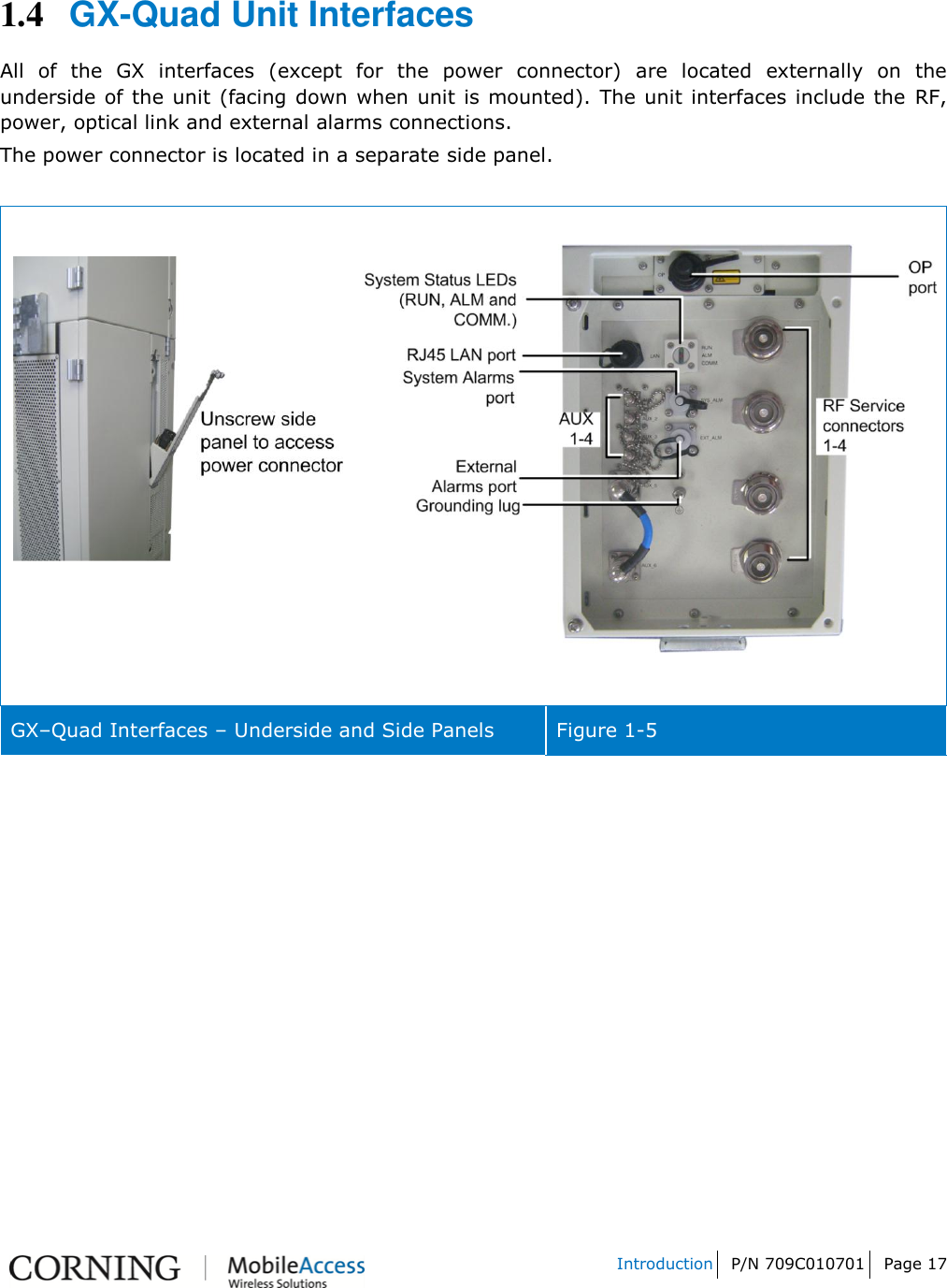
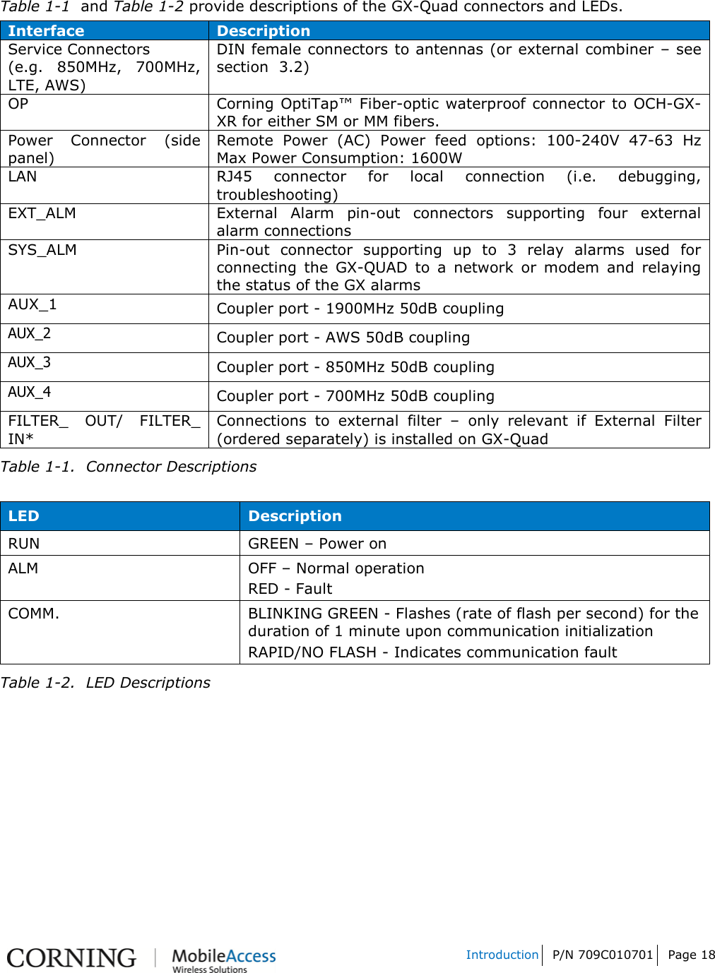
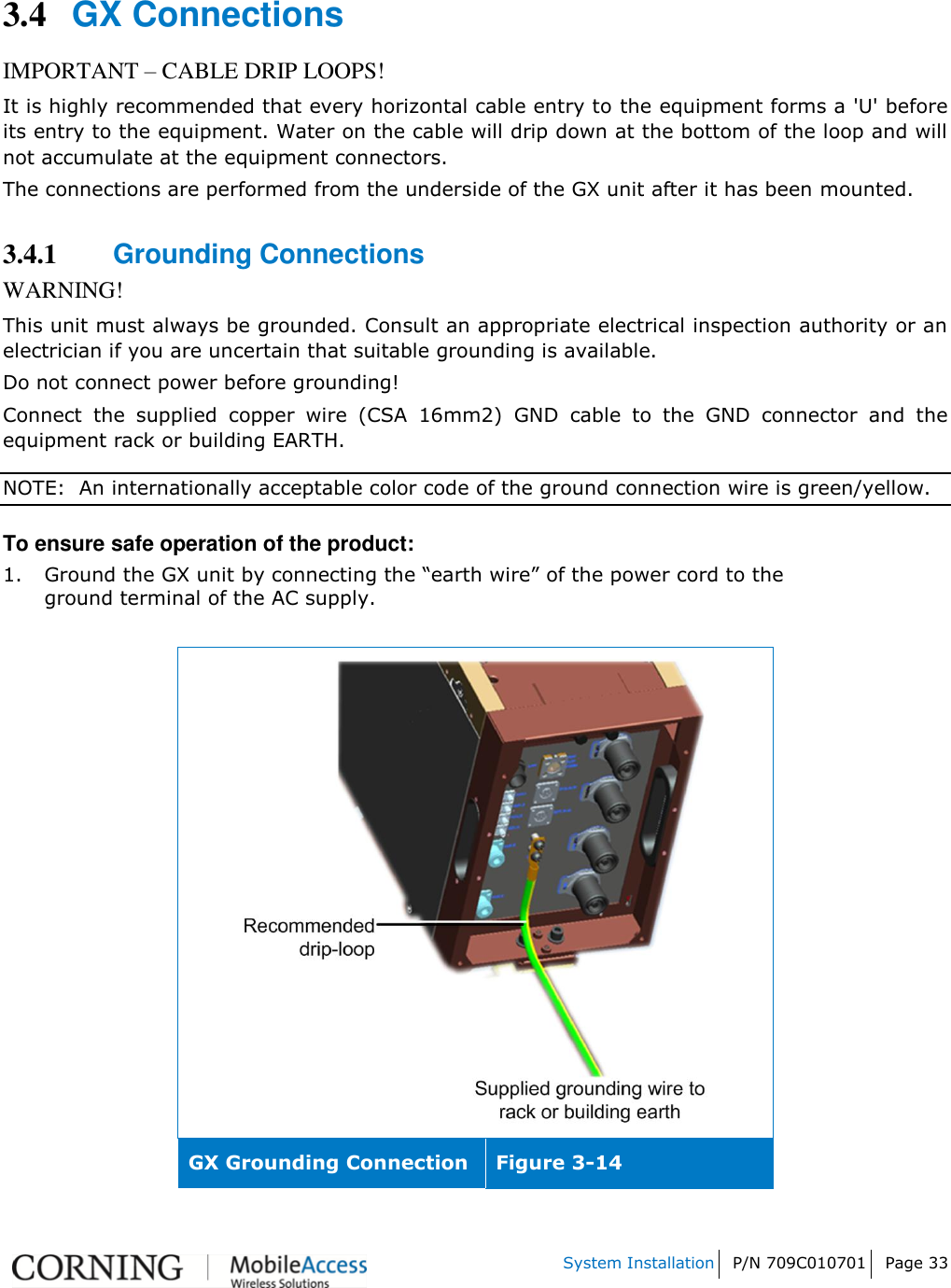
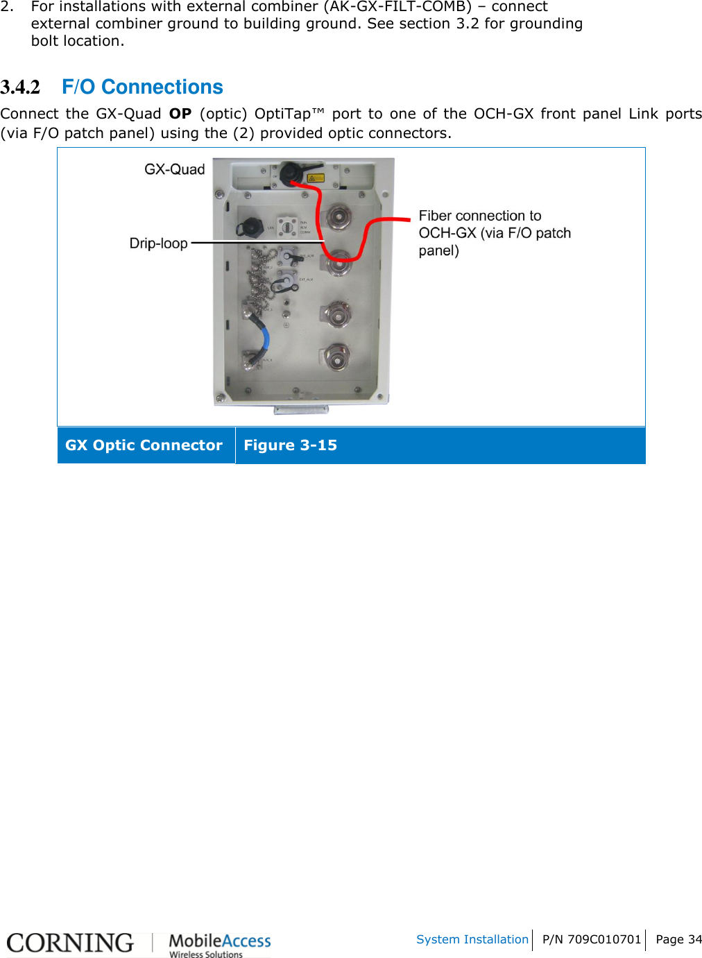
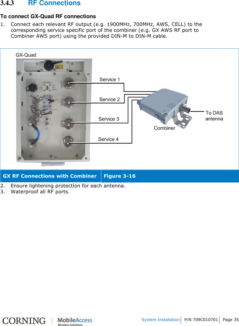
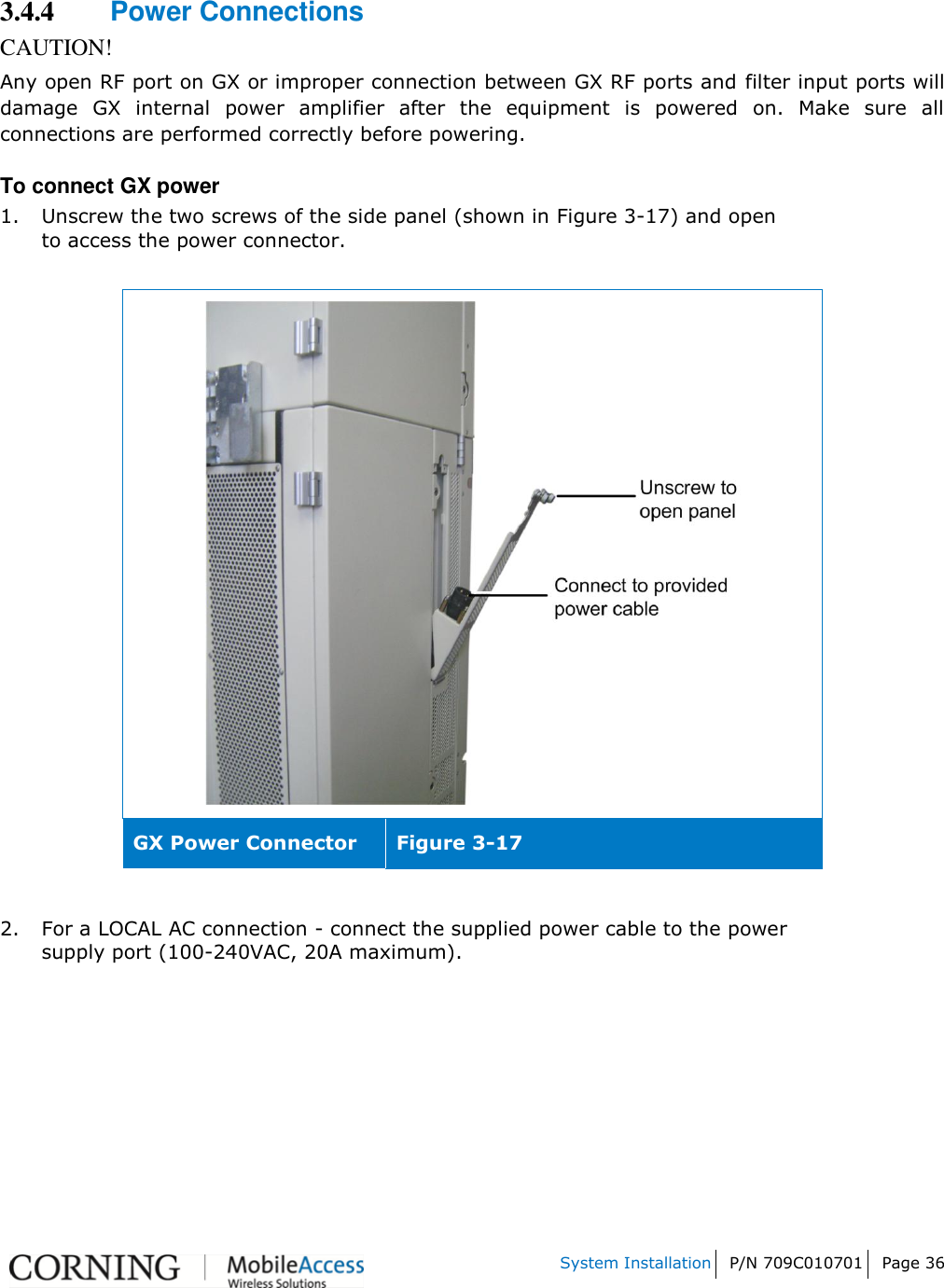
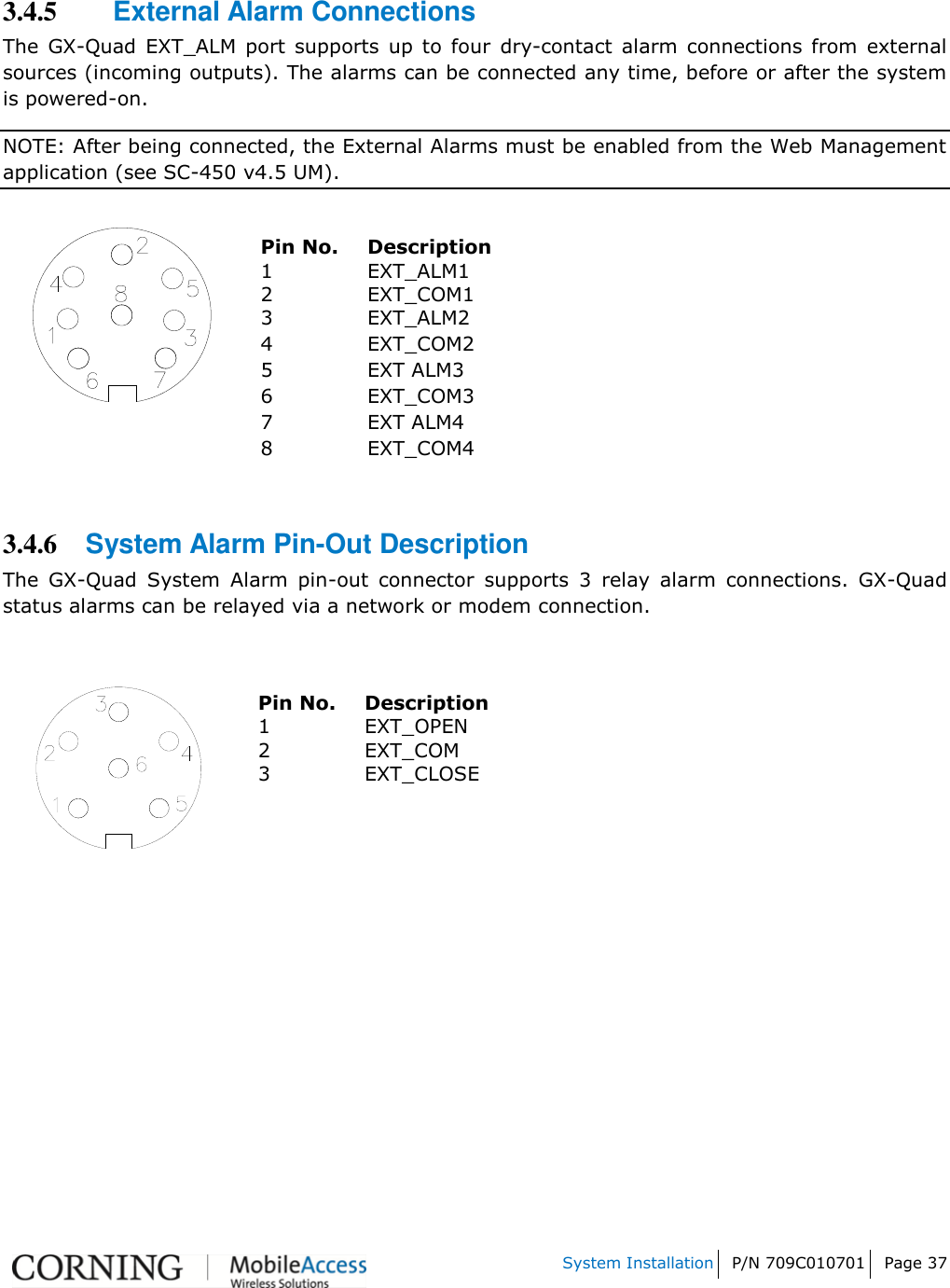
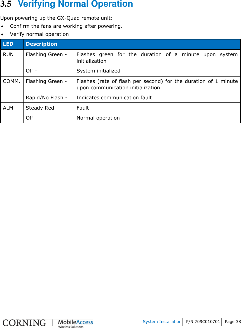
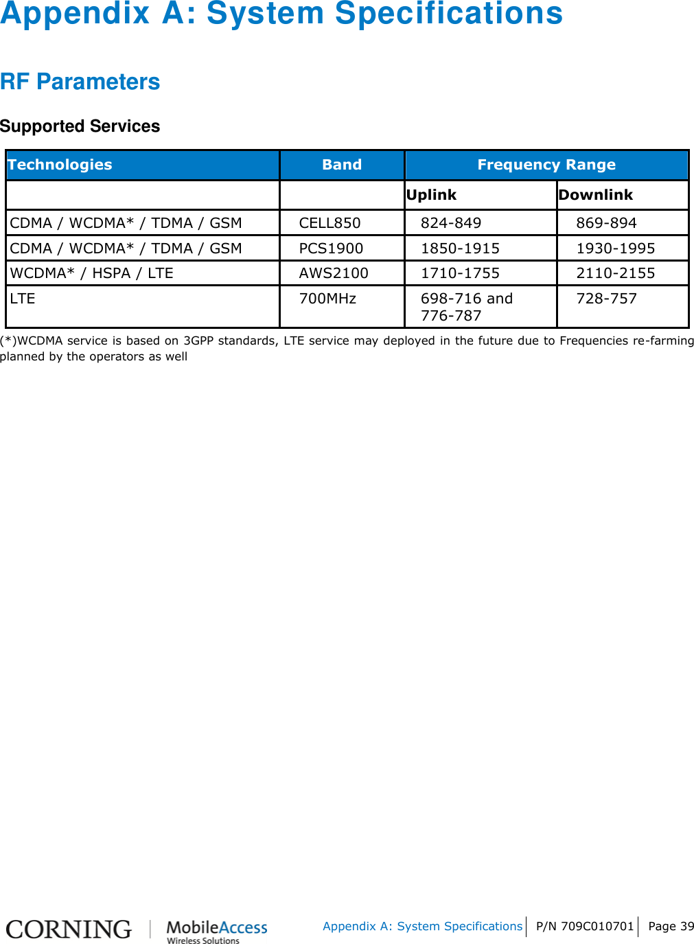
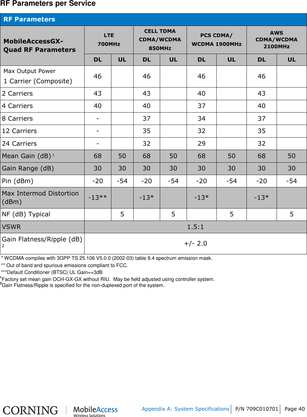
User Manual
Users Manual Final
Navigation menu
Upload a User Manual
Namespaces
Wiki Guide
HTML
PDF
Info
Views
User Manual
Discussion / Help
Navigation