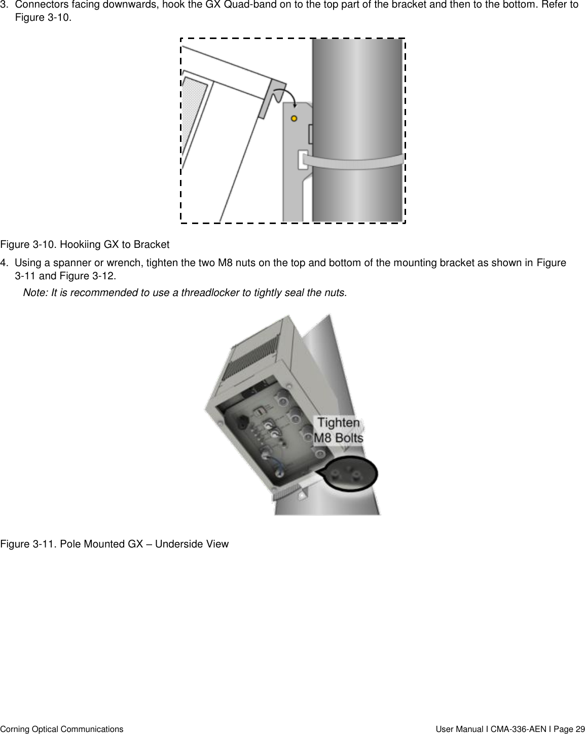
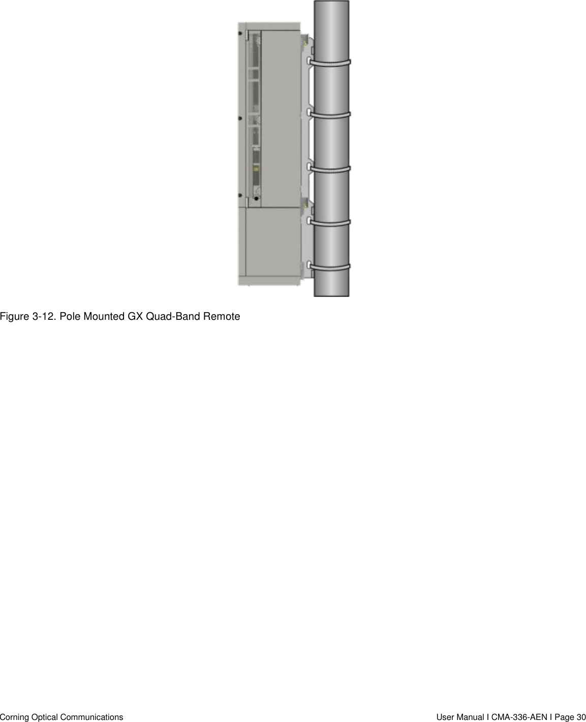
Corning Optical Communication GXCPLA3 GX 40W Quad-BAnd Remote Unit User Manual GX 40 W Quad Band Remote
Corning Optical Communication Wireless GX 40W Quad-BAnd Remote Unit GX 40 W Quad Band Remote
UserManual.wiki
>
Corning Optical Communication
>
GXCPLA3 User Manual
user manual
Navigation menu
Upload a User Manual
Namespaces
Wiki Guide
HTML
PDF
Info
Views
User Manual
Discussion / Help
Navigation
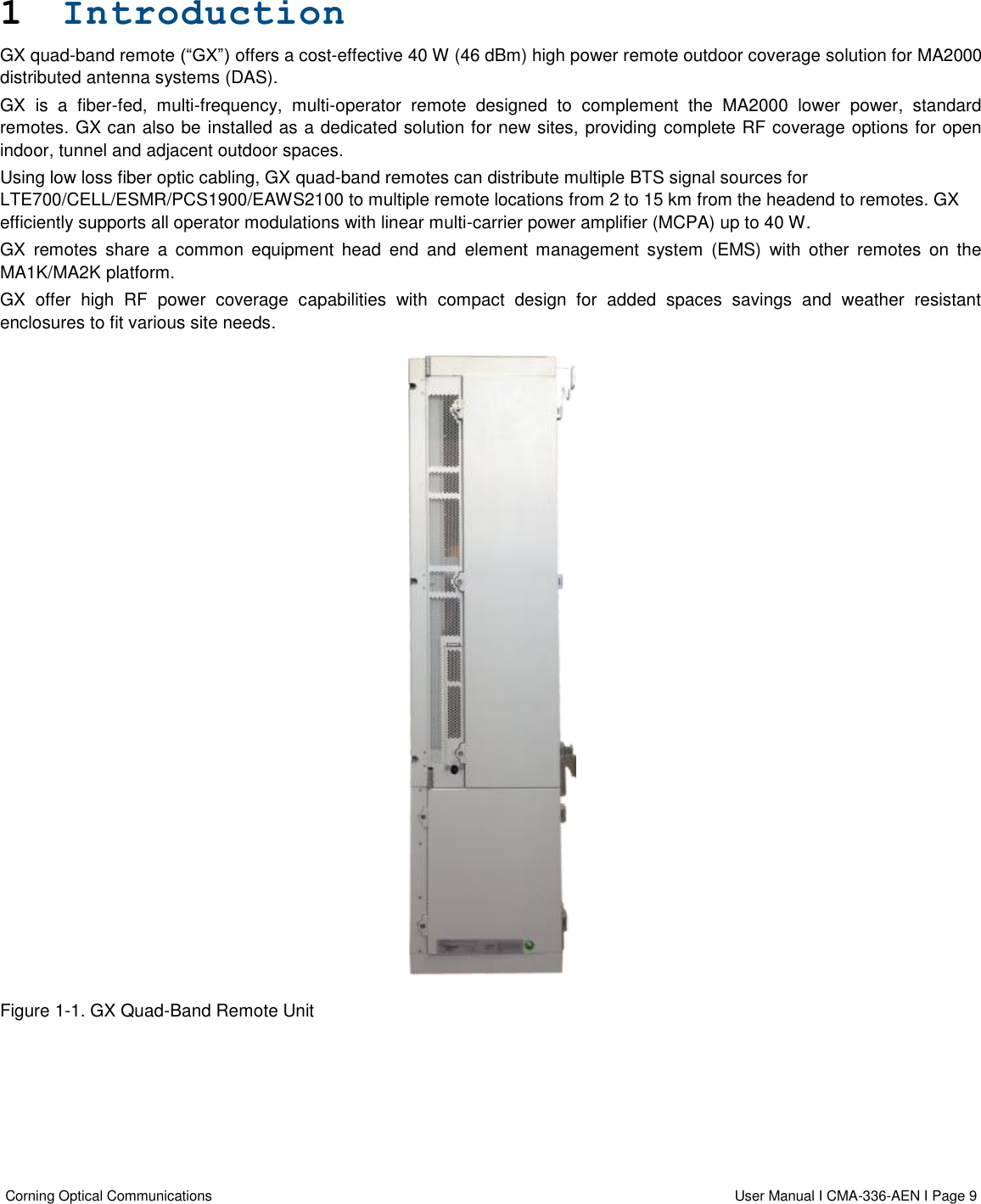
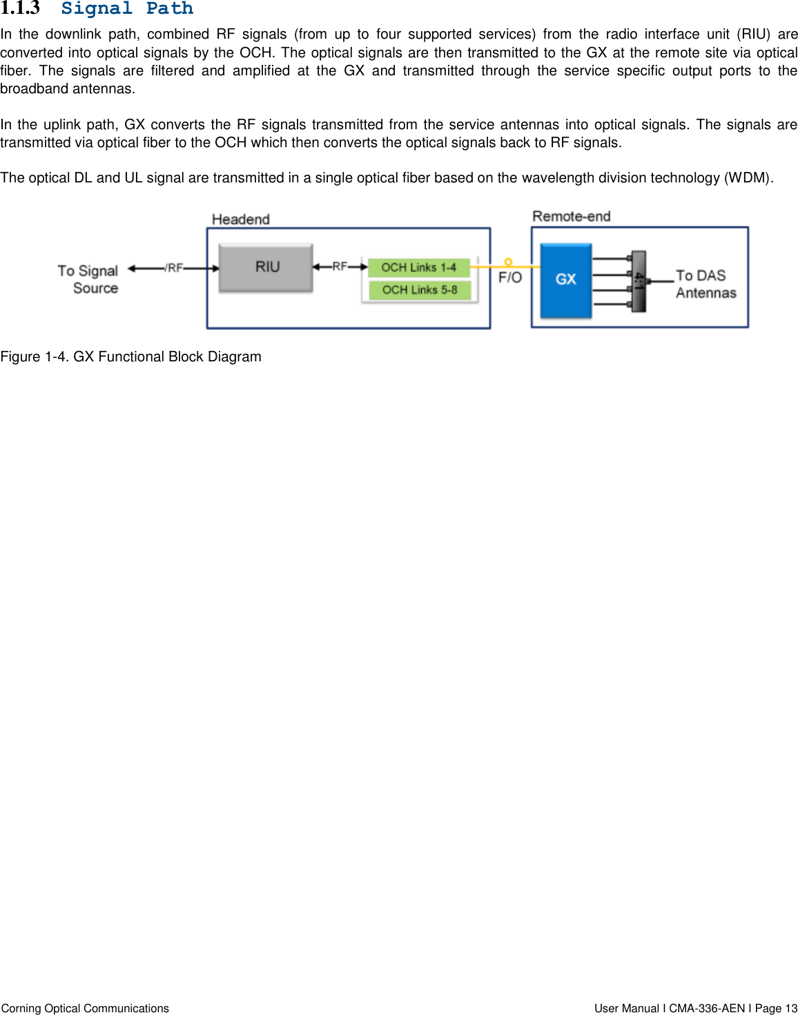
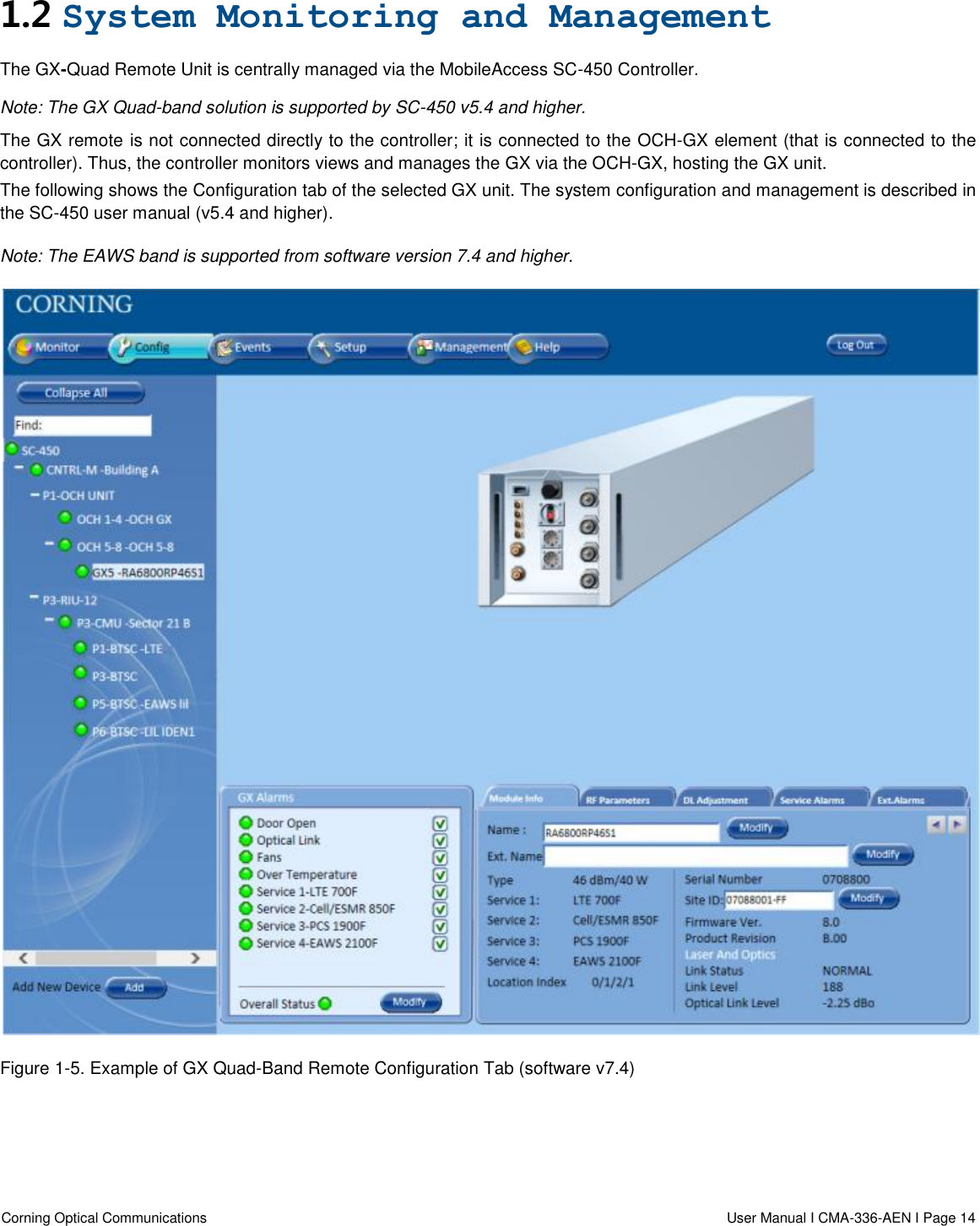
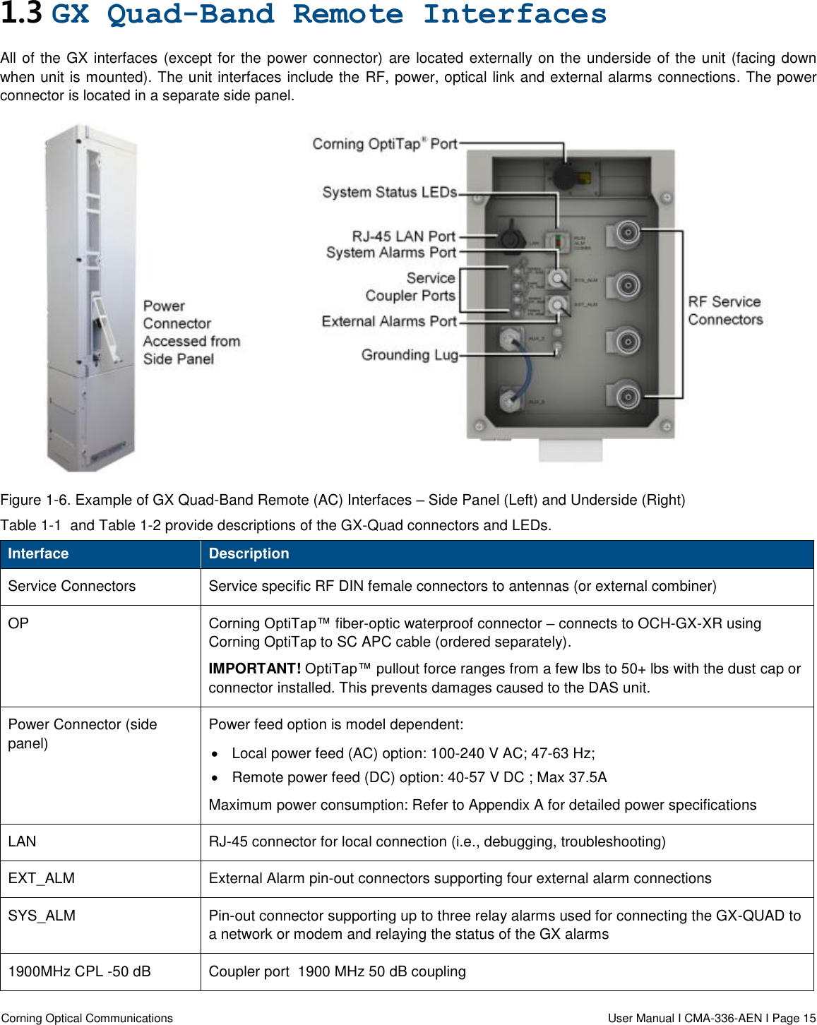
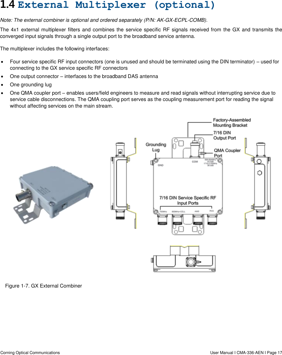
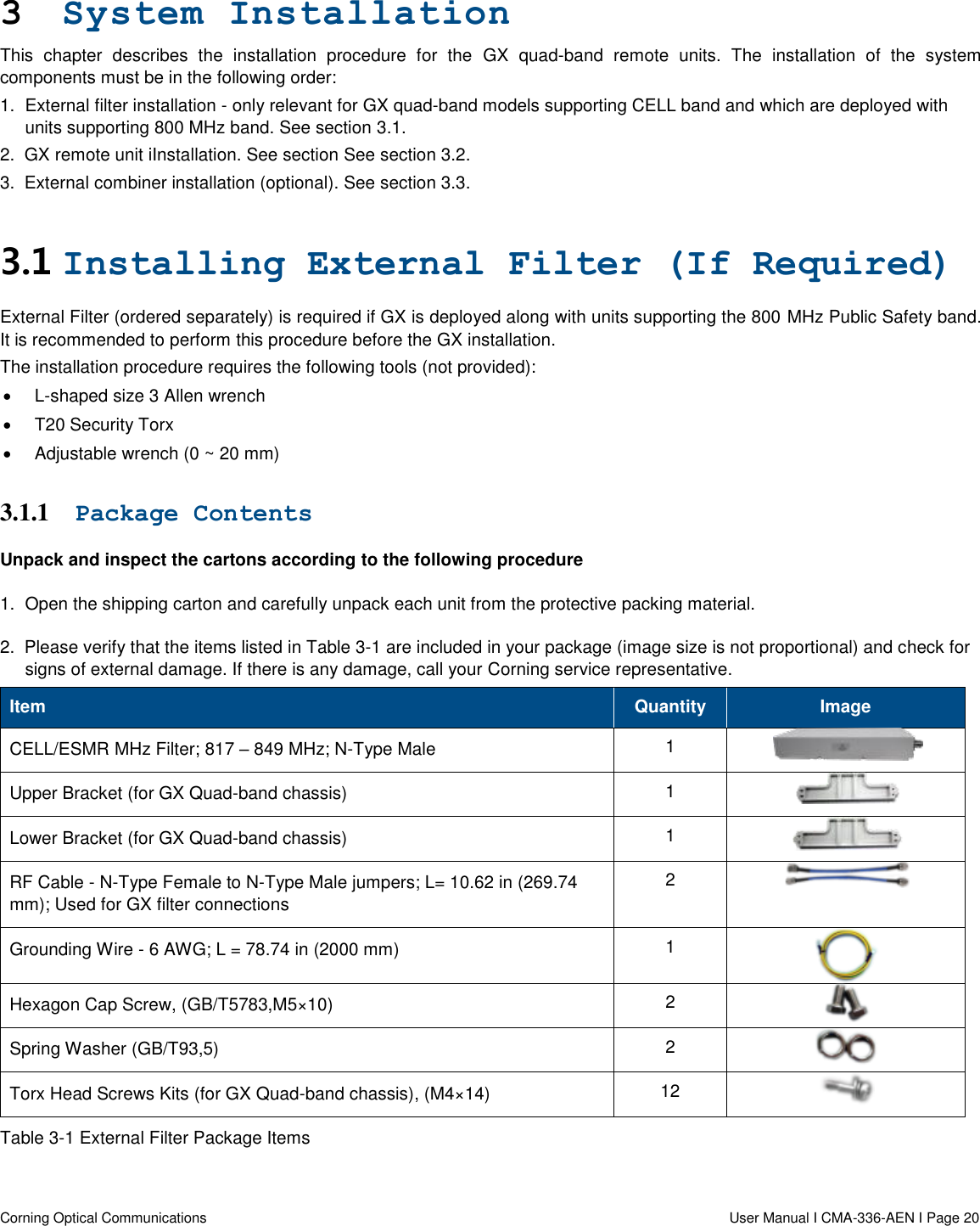
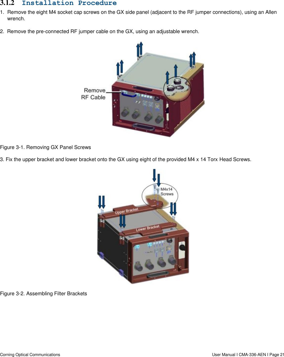
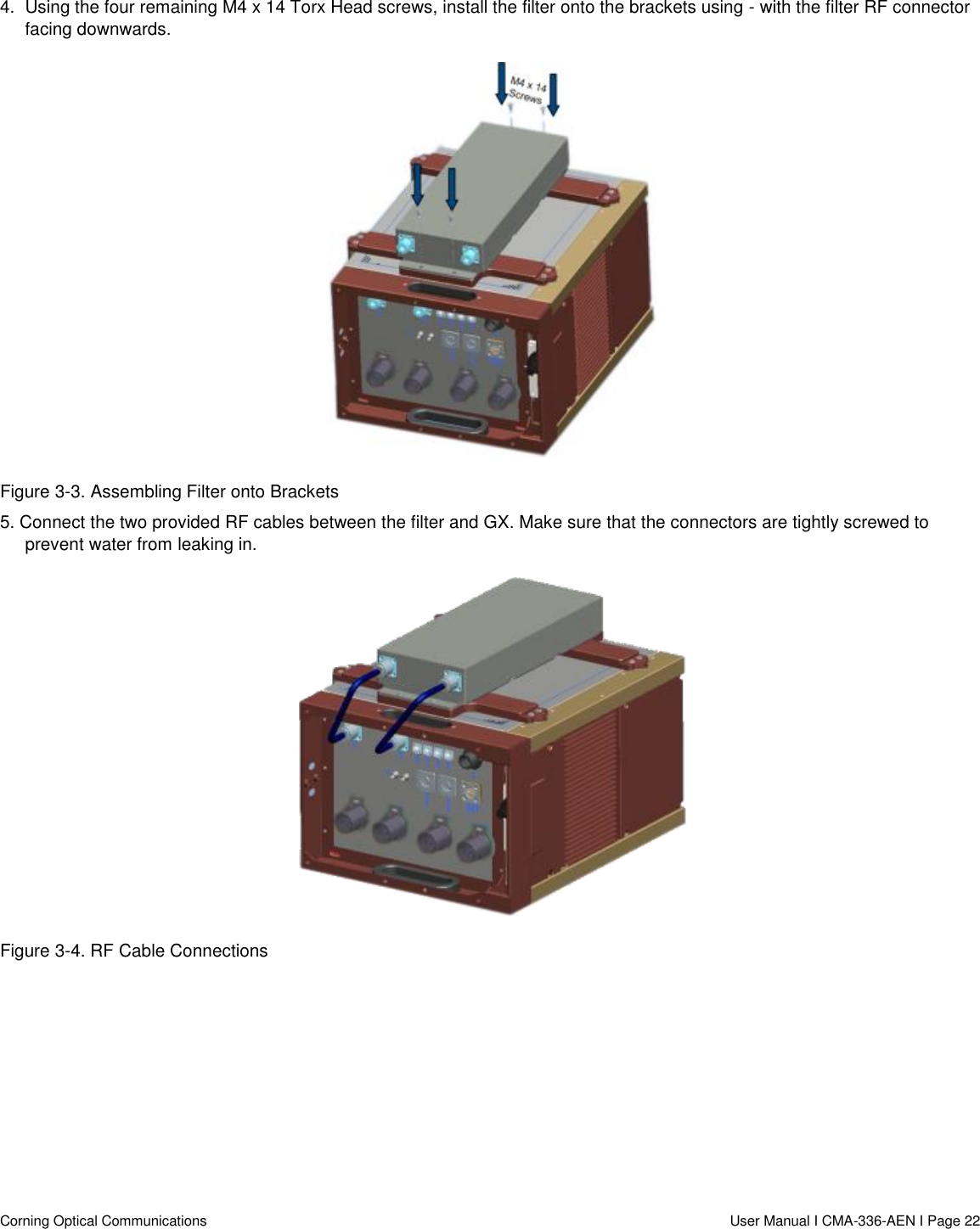
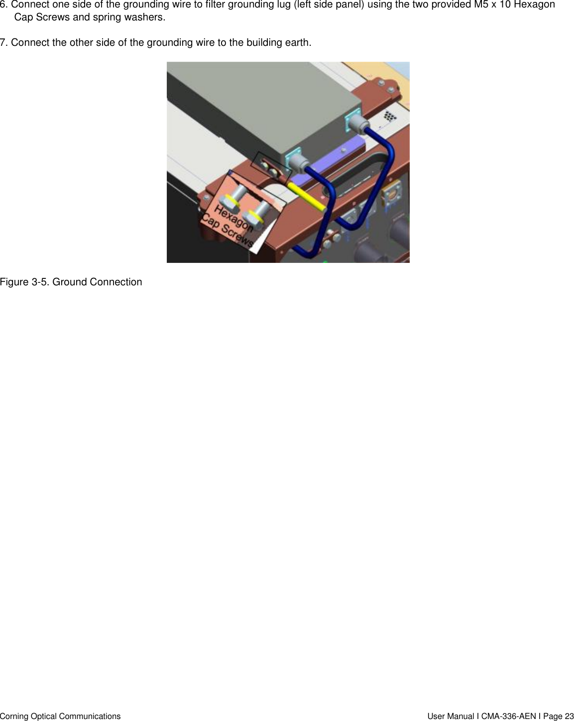
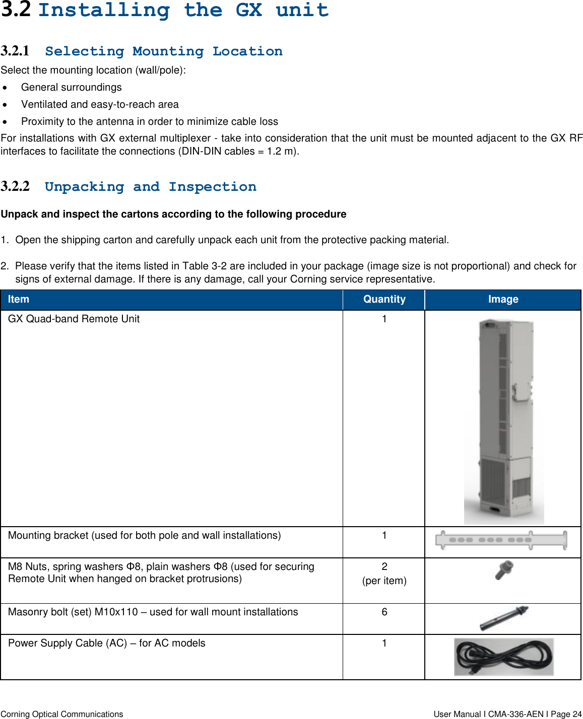
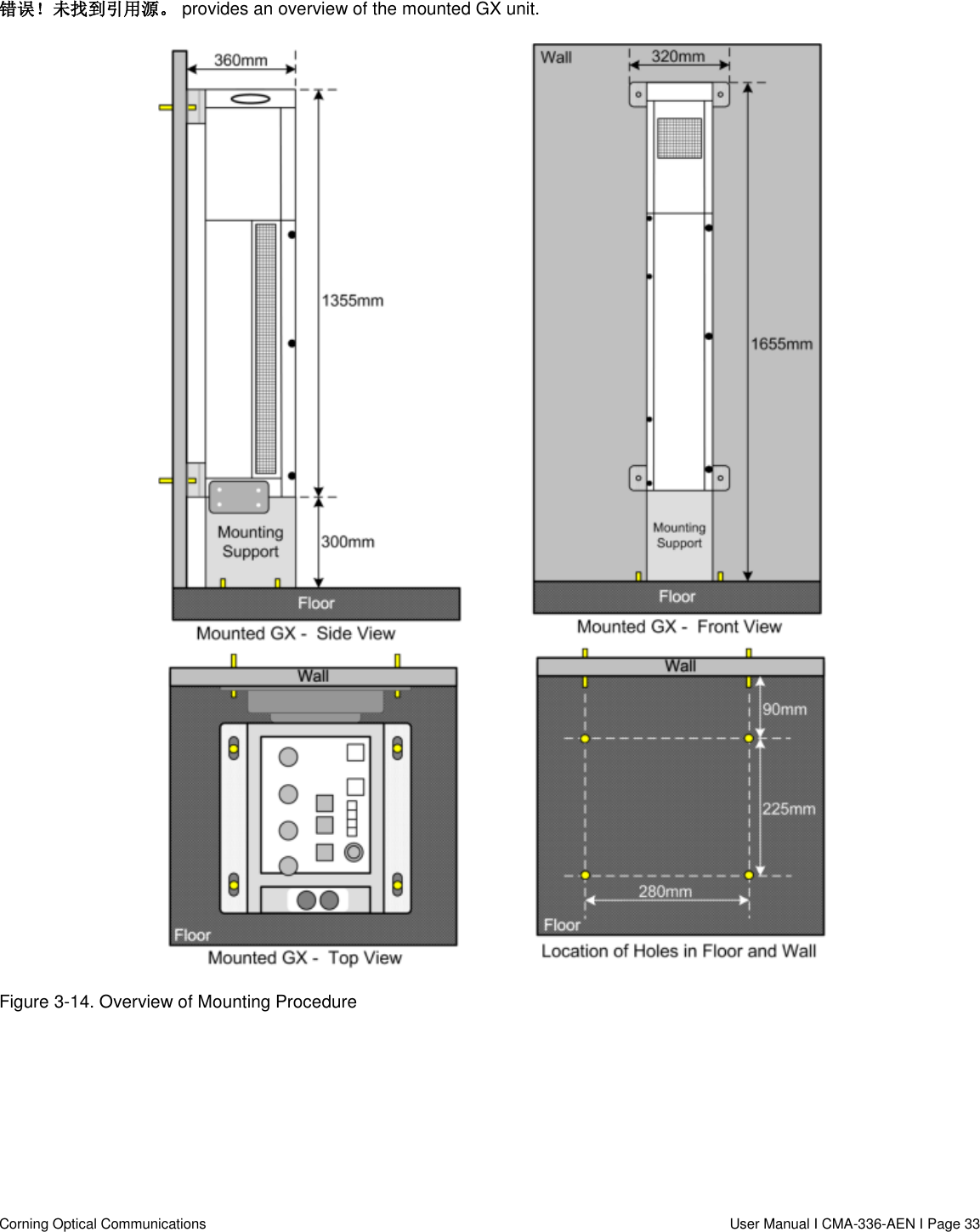
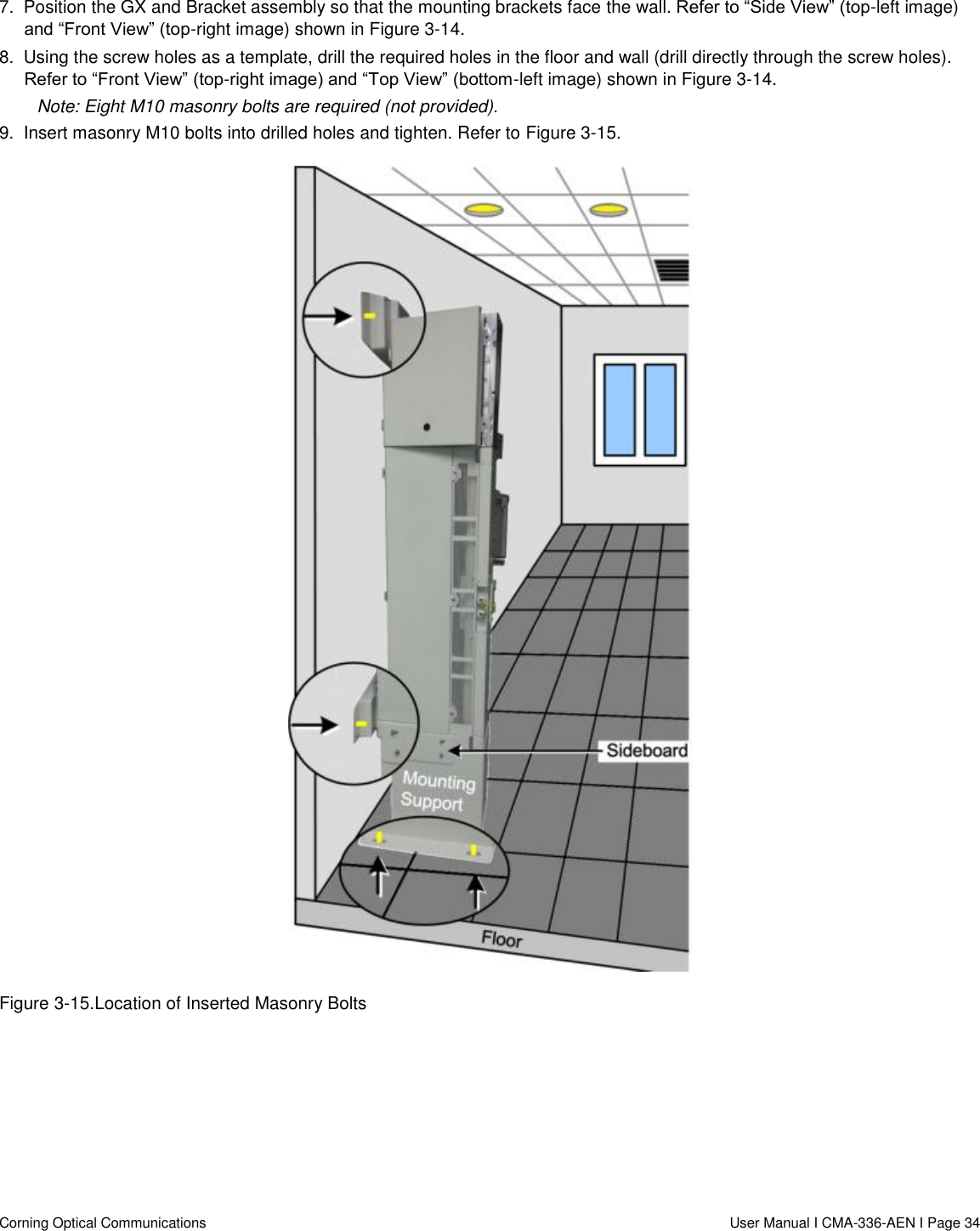
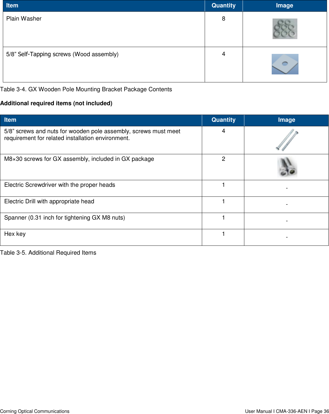
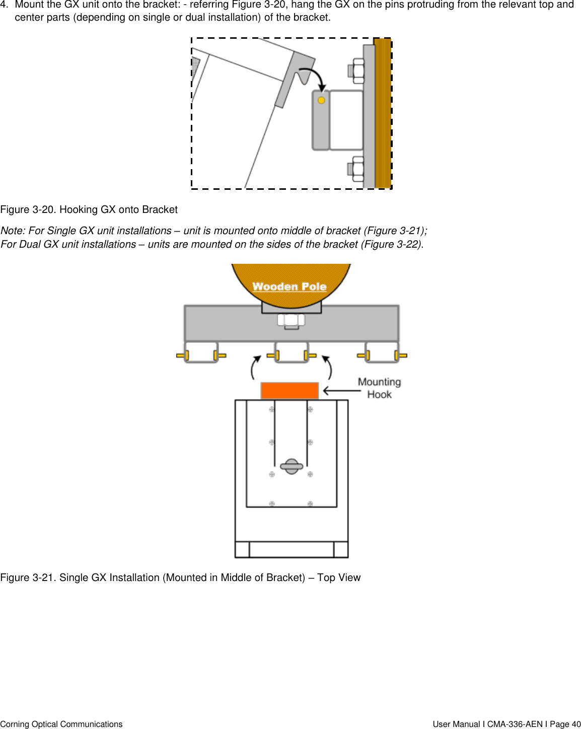
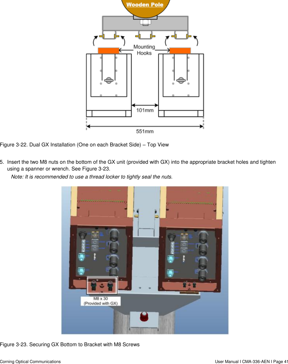
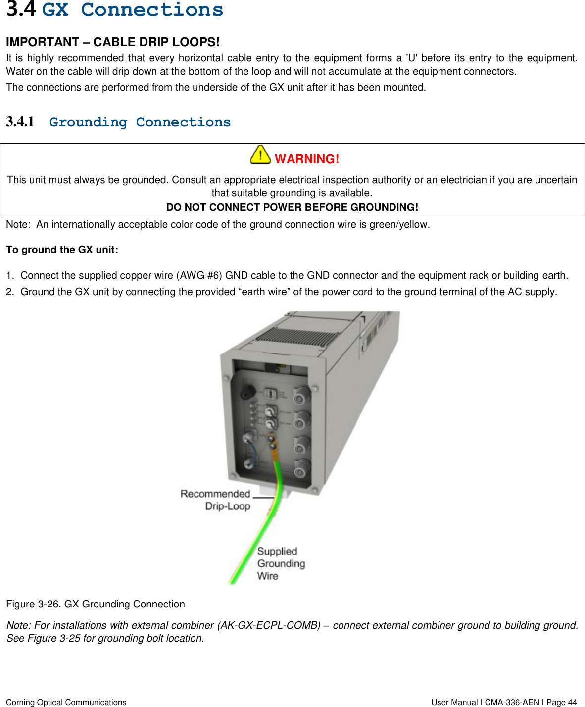
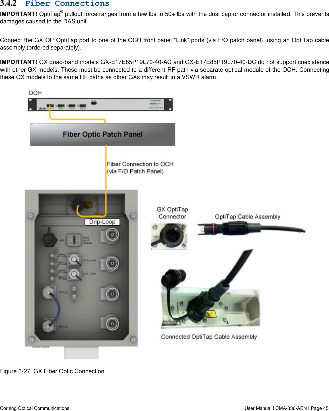
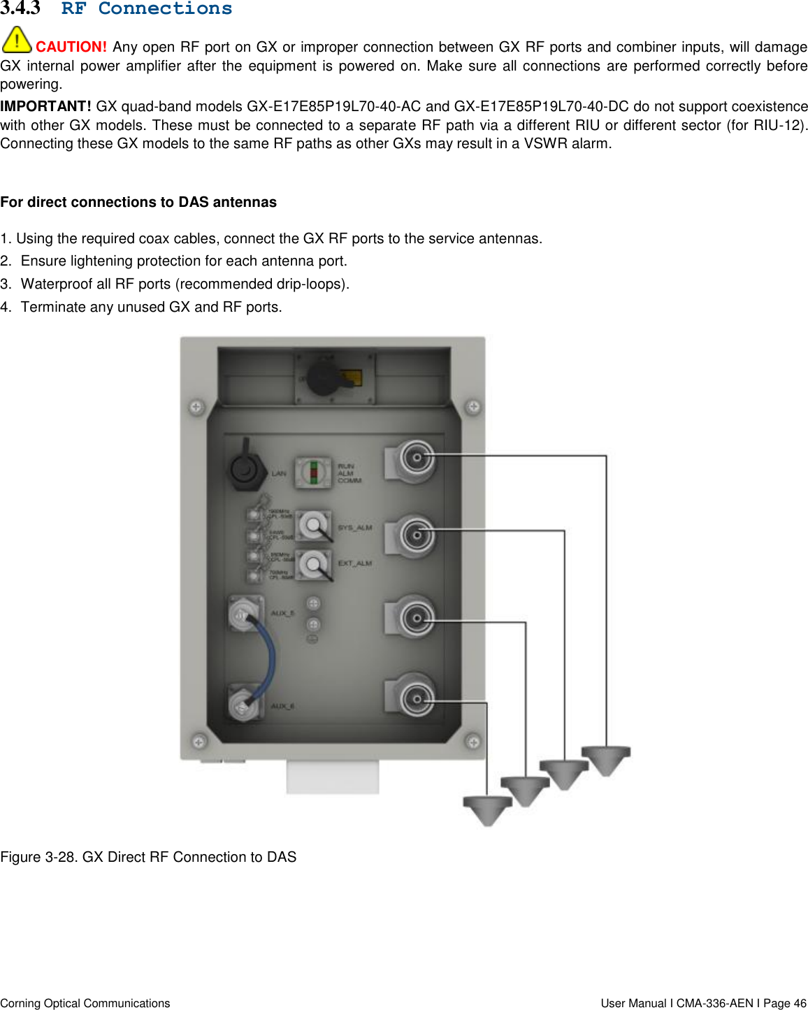
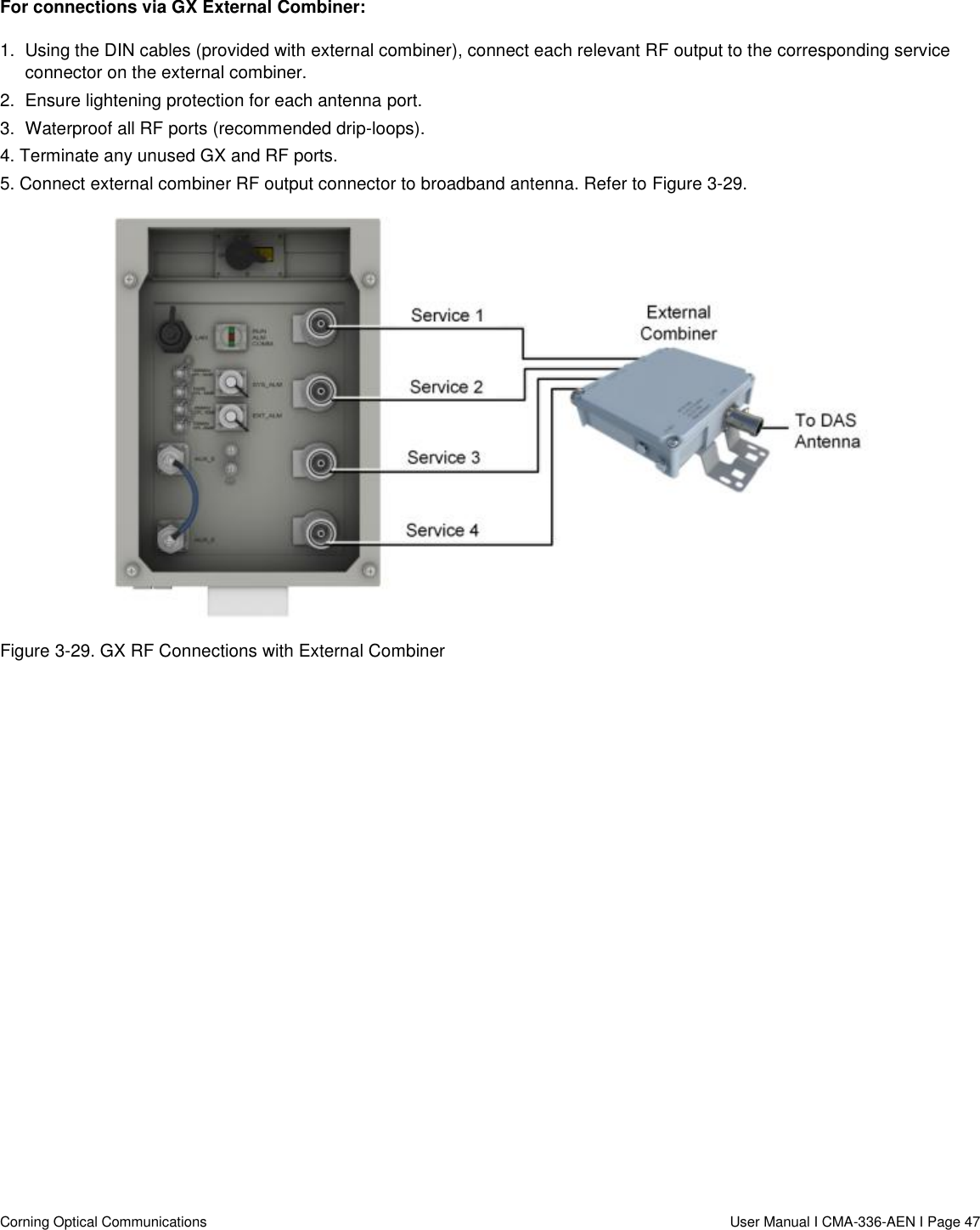
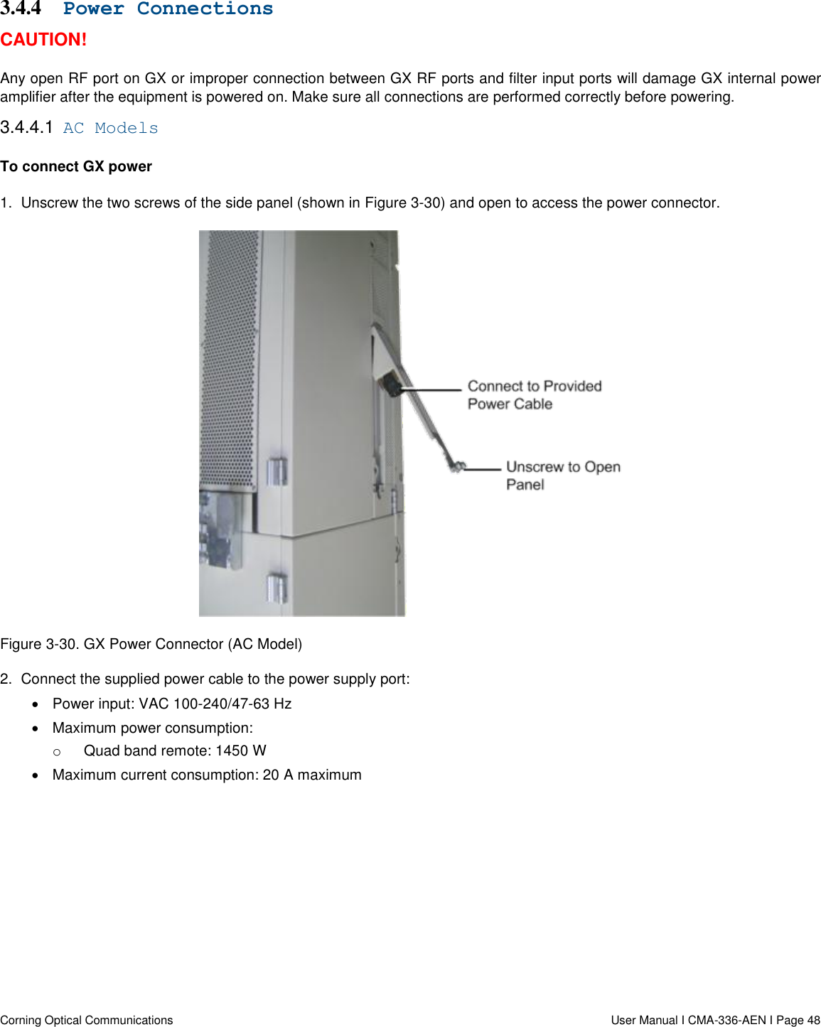
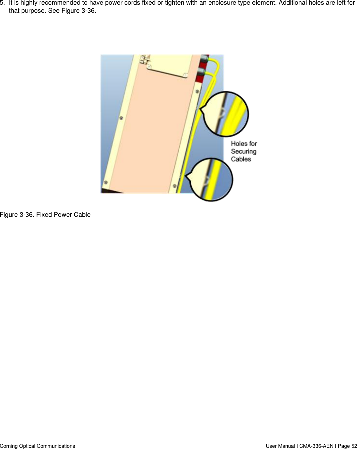
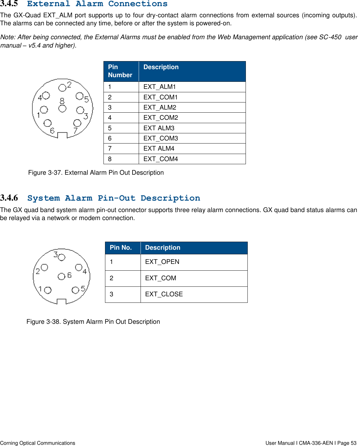
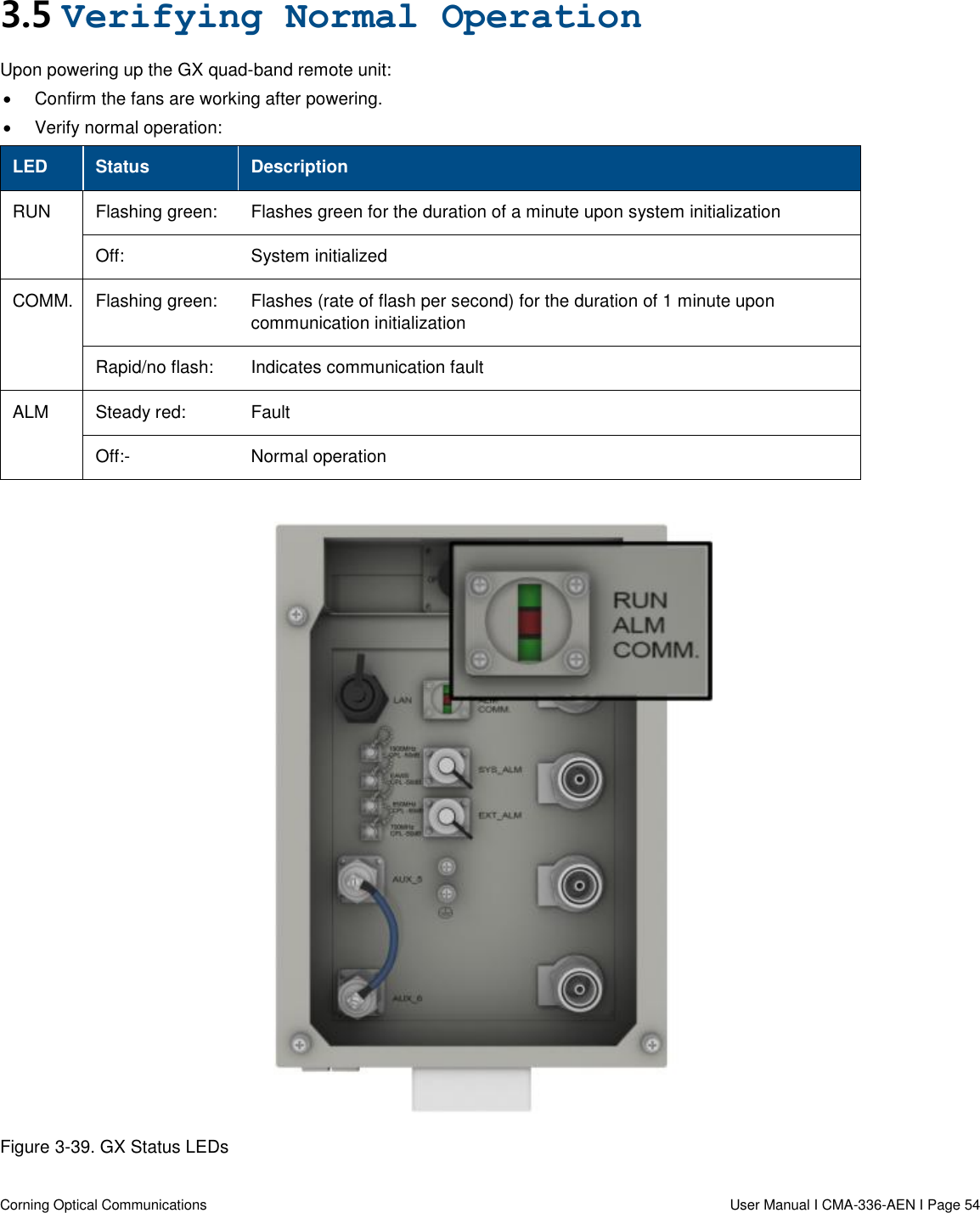
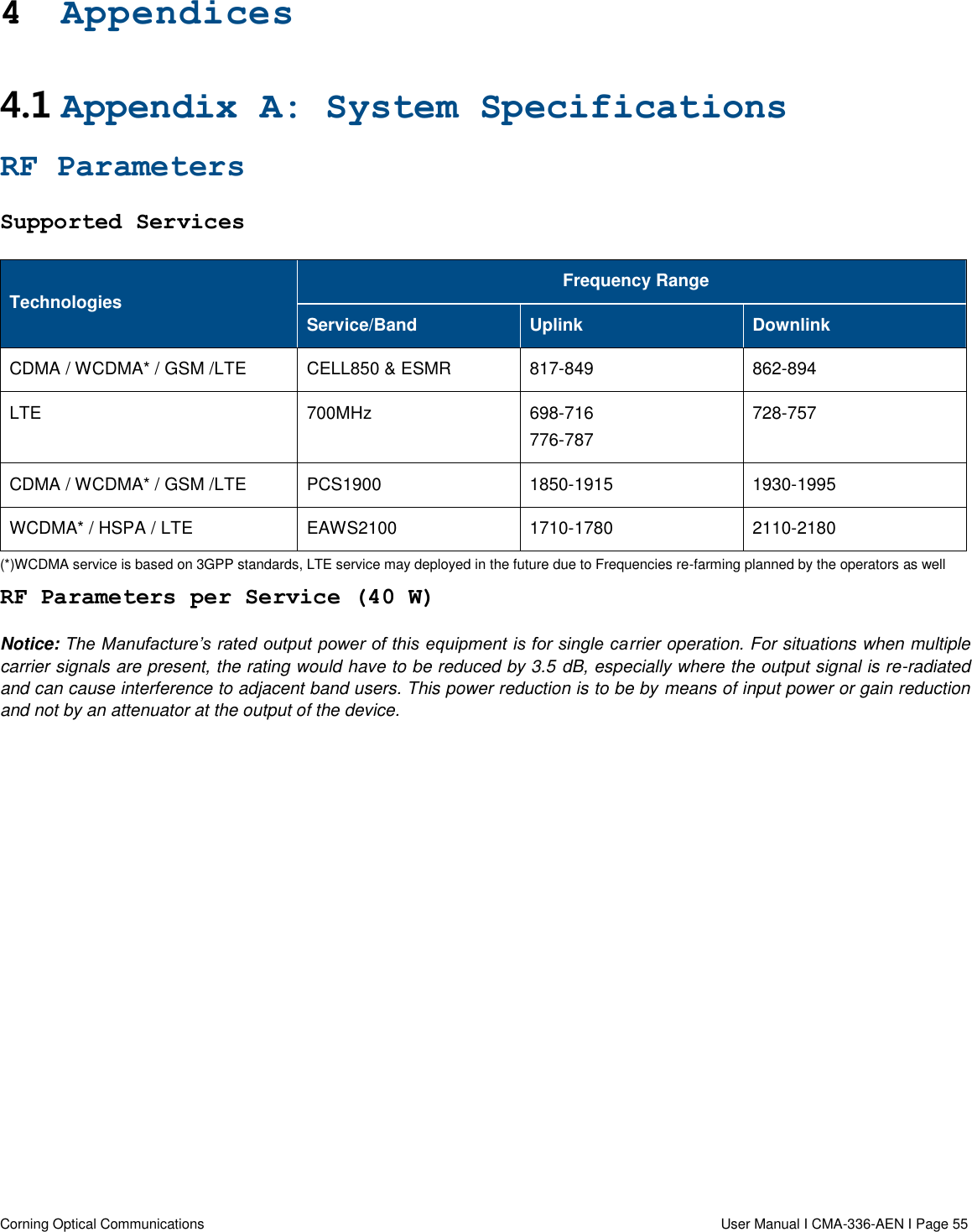
![Corning Optical Communications User Manual I CMA-336-AEN I Page 35 3.2.5.2 Wooden Pole Mount Installation This section provides instructions on how to mount the GX quad-band unit on wooden poles using the AK-GX-QUAD-BRKT-WDPOLE accessory kit (ordered separately). Note the following: This bracket is designed for installations on wooden poles only. Up to two GX units can be mounted on a single bracket. One on each side. Two people are required for mounting each GX unit onto the bracket. For GX models supporting the CELL band, requiring an external filter (if deployed along with 800 MHz band MA1000/MA2000 units) – install filter before mounting the GX on to the bracket [see GX CELL 850 MHz cavity filter quick installation sheet (CMA-378-AEN) for details]. The GX unit is mounted onto the pole with the connectors facing downwards. Weight: GX (per unit) = ~156.5 lbs (71kg); Bracket = 30.9 lbs (14 kg). Package Contents Check your package contents to verify that the items in the packing list are included and that there are no signs of external damage. Item Quantity Image Pole Bracket Top 1 Pole Bracket Middle 1 Pole Bracket Bottom 1 M6×16 Hex Socket Head Cap Screw (Bracket Assembly) 8 Spring Washer 8](https://usermanual.wiki/Corning-Optical-Communication/GXCPLA3/User-Guide-3236078-Page-35.png)