Corning Optical Communication HX-2500-SISO Optical Repeater name - HX-2500-SISO User Manual HX 2 5 GHz TDD
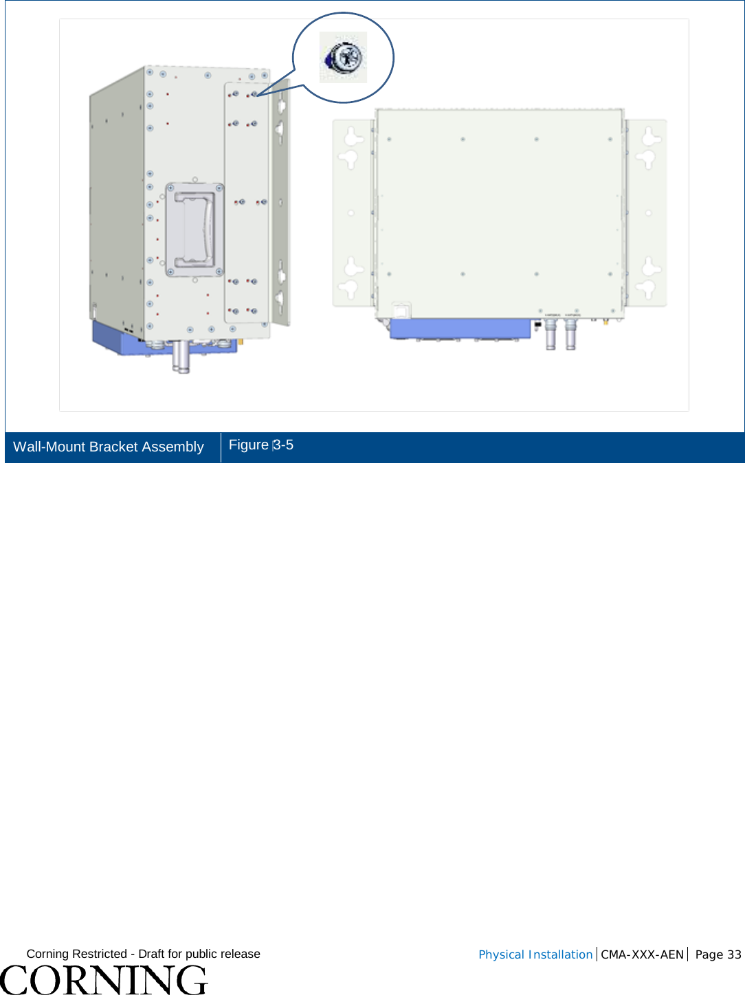
Corning Optical Communication Wireless Optical Repeater name - HX-2500-SISO HX 2 5 GHz TDD
UserManual.wiki
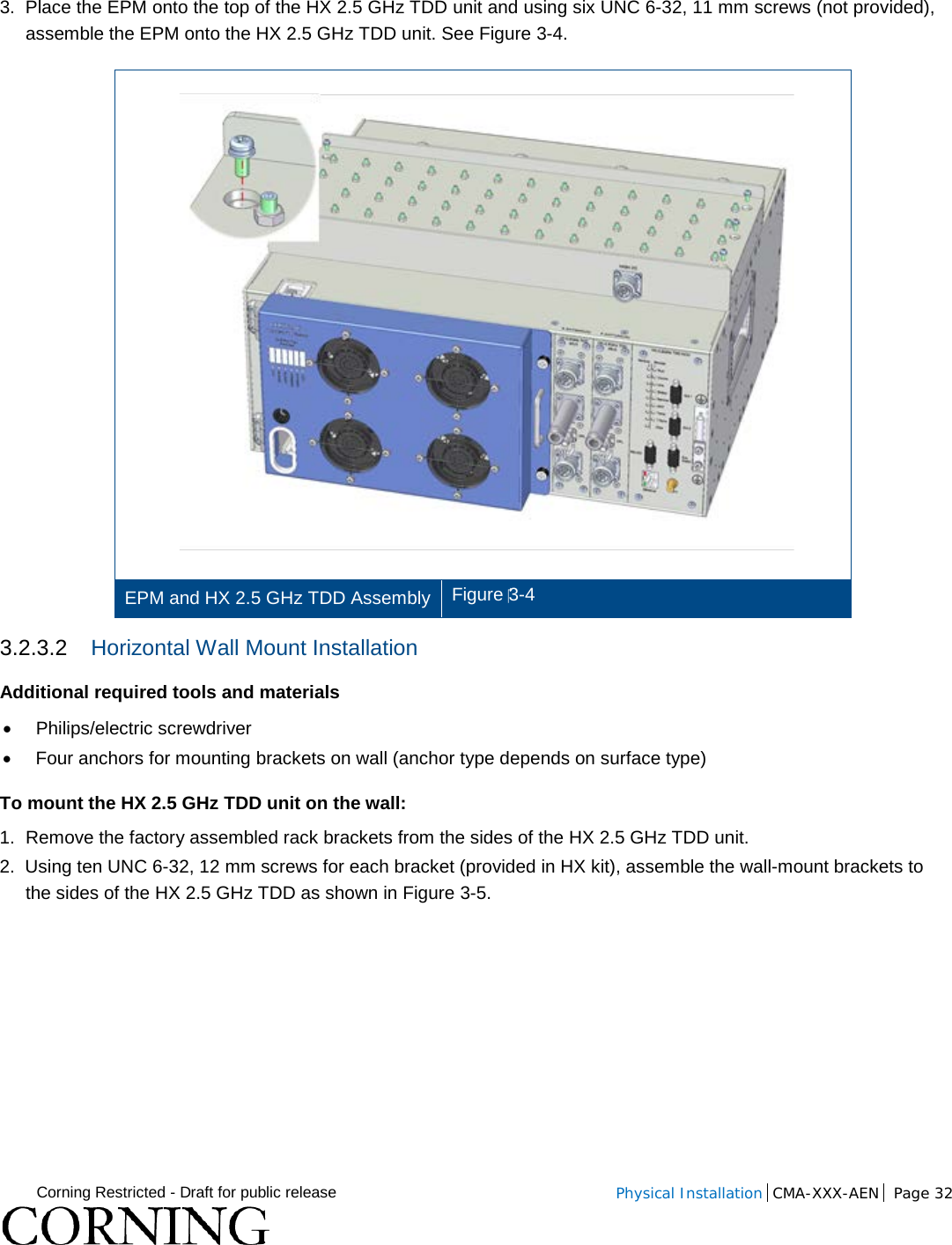
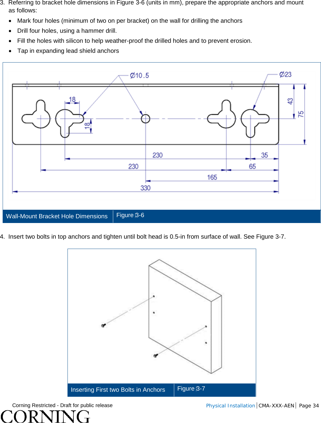
>
Corning Optical Communication
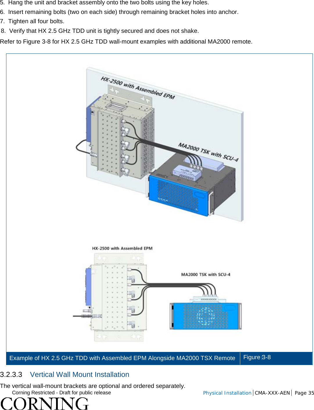
>
HX 2500 SISO User Manual
User Manual_HX_SPARK-SISO_20160215
Navigation menu
Upload a User Manual
Namespaces
Wiki Guide
HTML
PDF
Info
Views
User Manual
Discussion / Help
Navigation
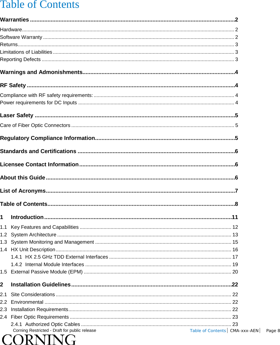
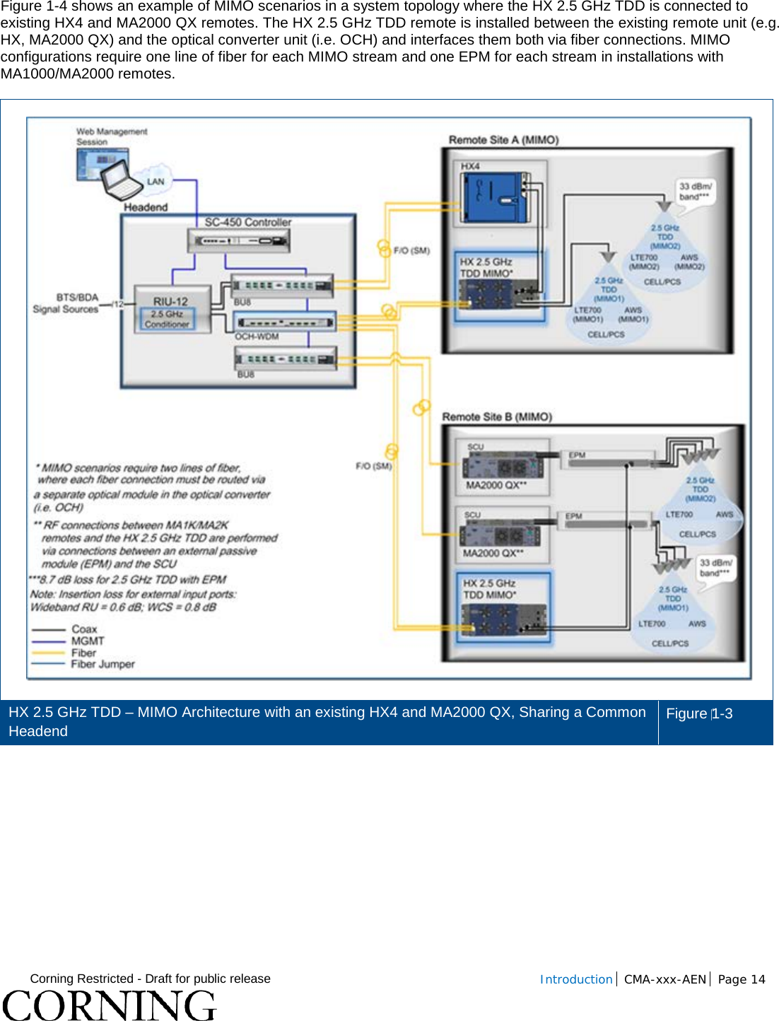
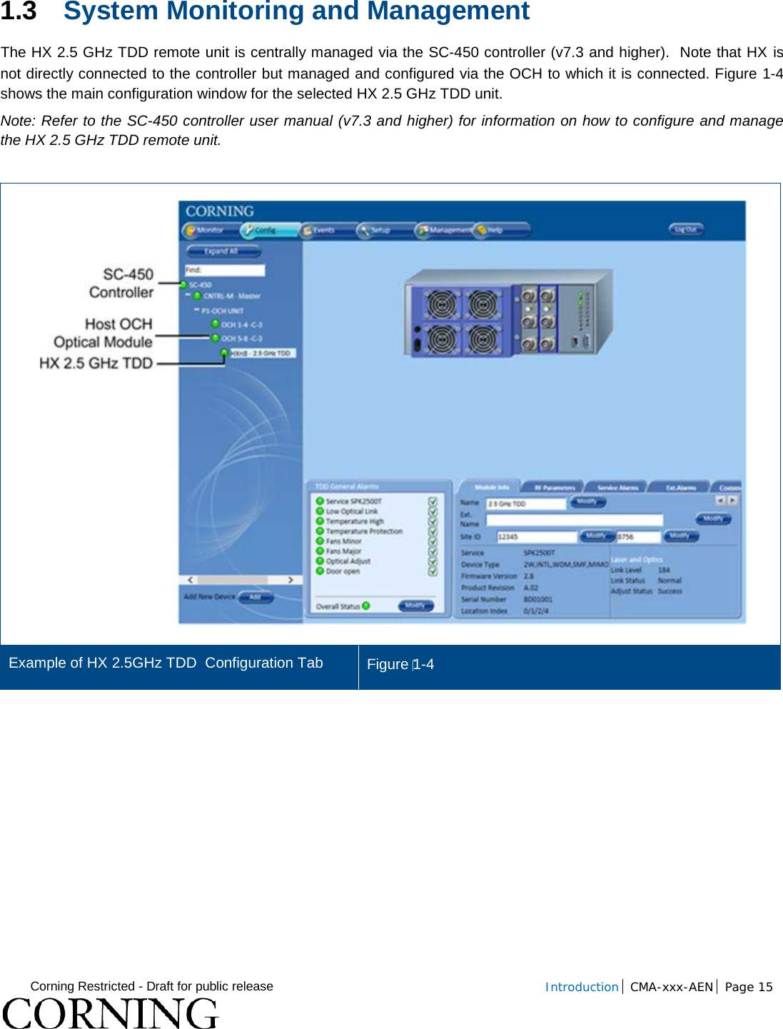
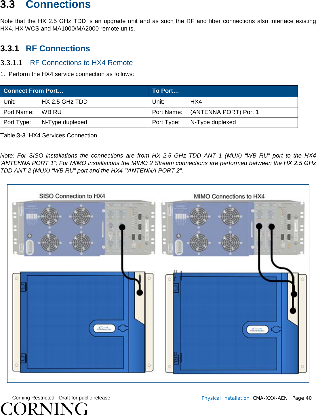
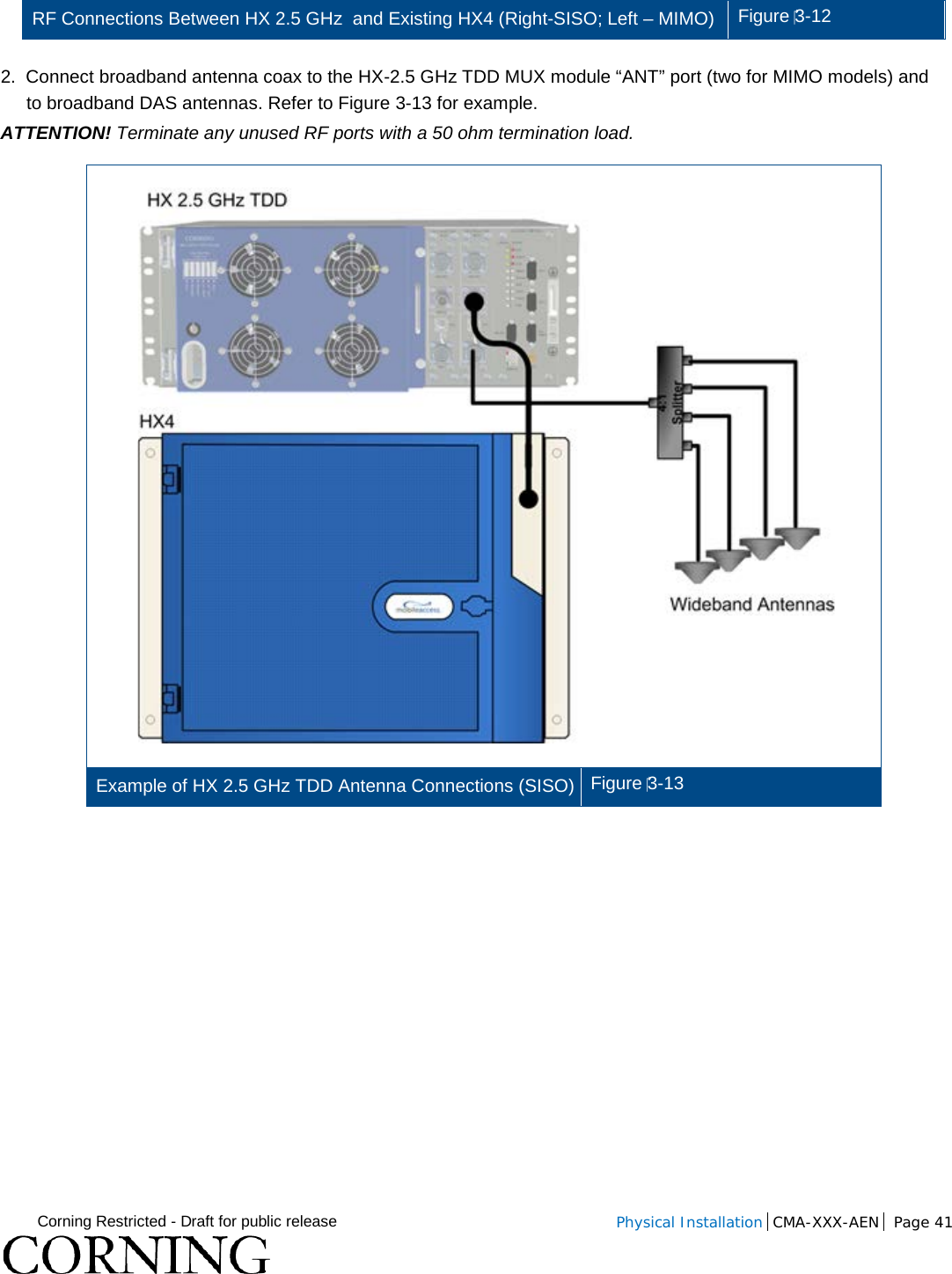
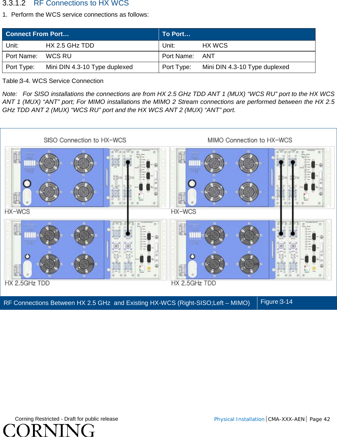
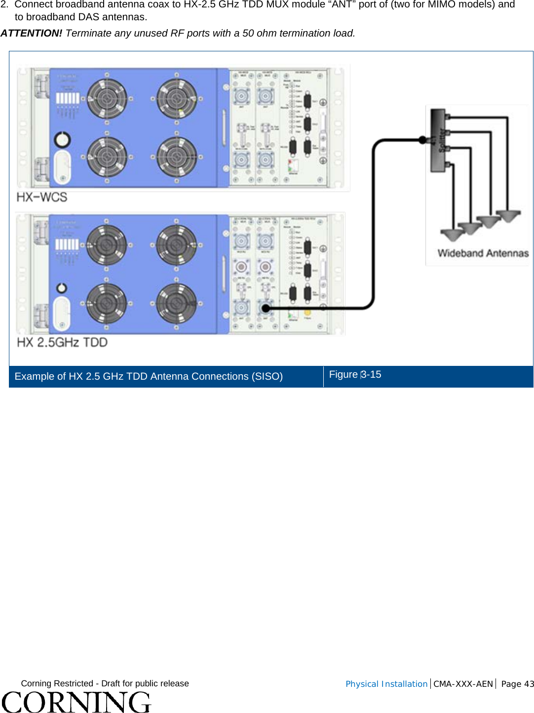
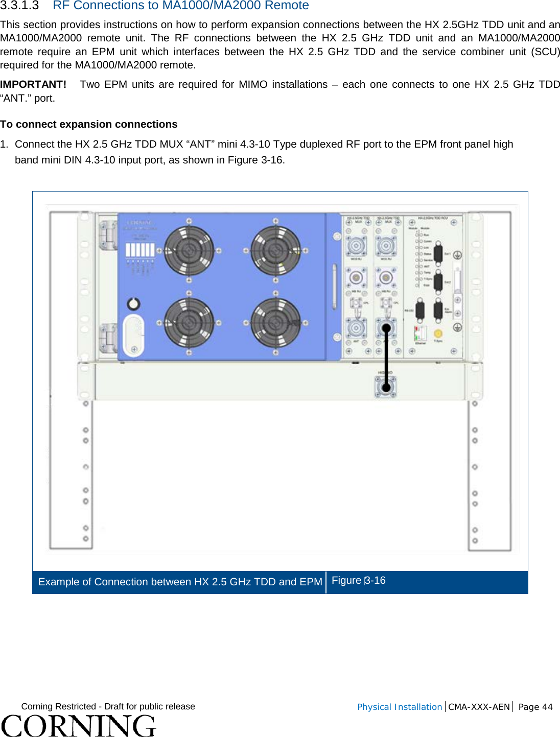
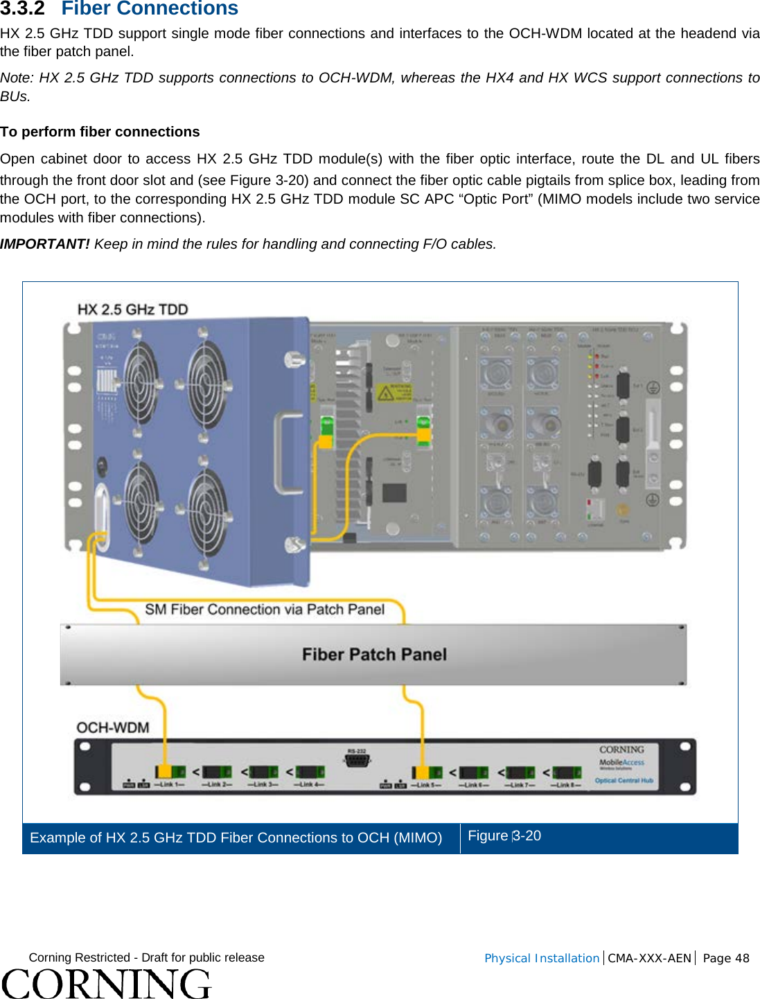
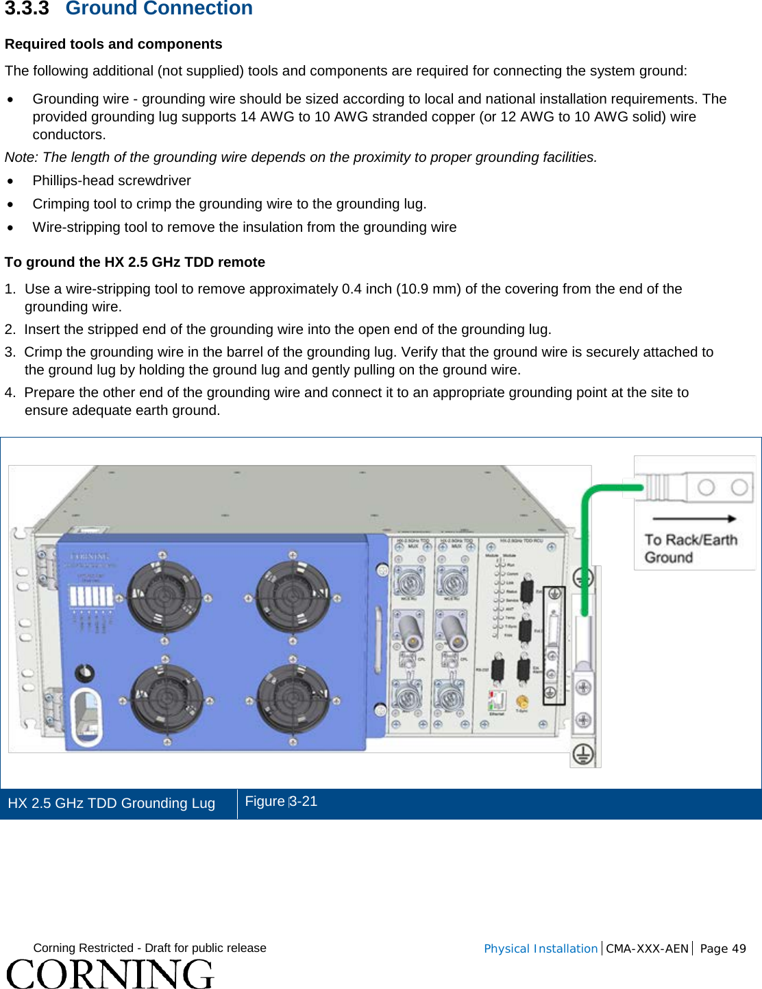
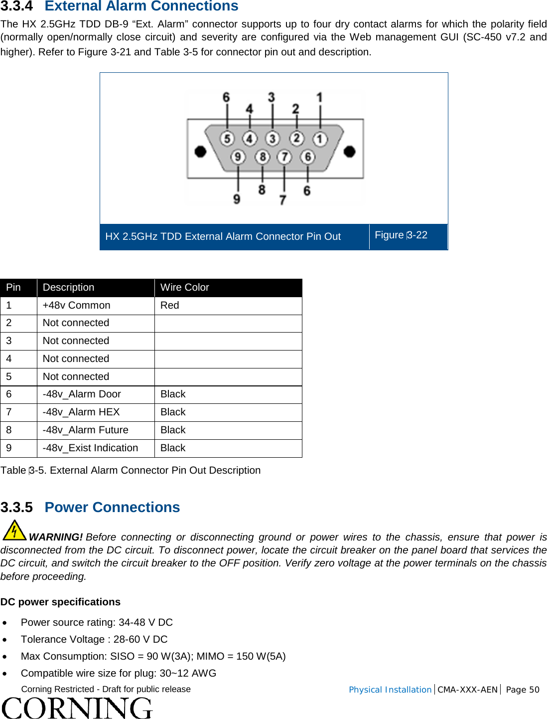
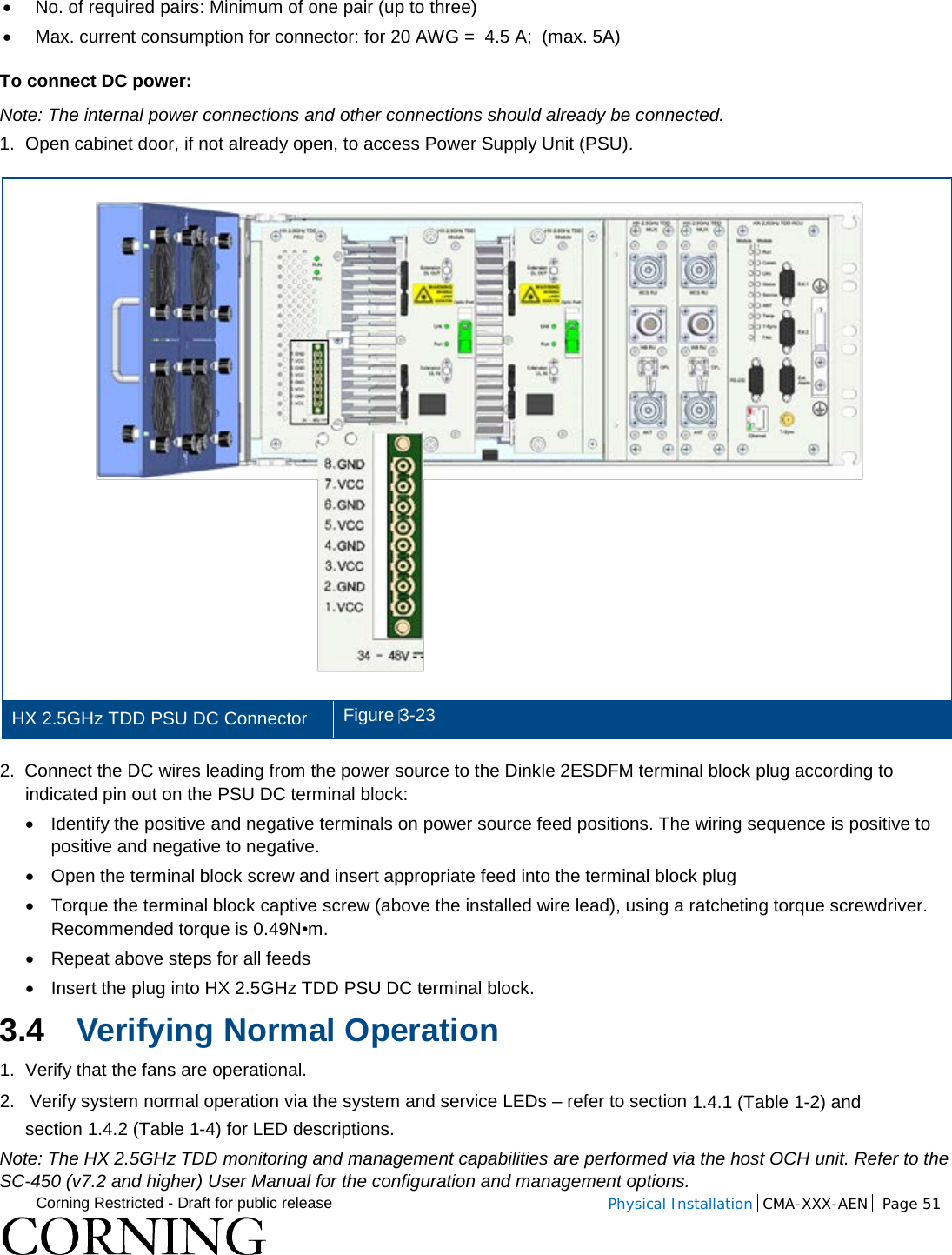
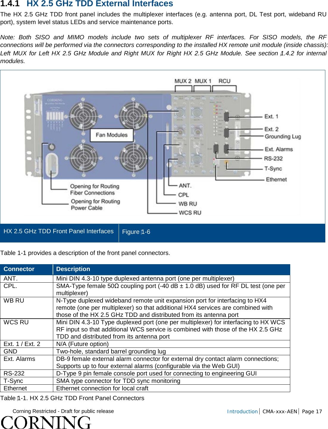
![Corning Restricted - Draft for public release Introduction CMA-xxx-AEN Page 16 1.4 HX Unit Description The HX 2.5GHz TDD unit consists of the following main modules: • RCU – Remote control unit; Includes status LEDs for each module and control ports • ANT (MUX) – Multiplexer [ANT. 1 MUX (right) for SISO; ANT. 2 MUX (left) for MIMO] including interfaces to HX WCS, HX4 and RF antennas/MA1000/MA2000 units (via EPM); combines signal sources additional external RF signals (when connected to HX unit and MA1000/MA2000 remote) while providing the proper filtering into a single antenna port • Module – [ANT. 1 (right) for SISO; ANT. 2 (left) for MIMO] Internal module that interfaces to the optical converter unit (OCH) connects via a single mode fiber pair and supports one service. The HX 2.5 GHz TDD module provides the additional amplification on the DL signals routed from the OCH towards the multiplexer. • Power Supply - DC power; Internal module The unit plot plan is provided on the left side of the enclosure door: HX 2.5 GHz TDD Unit Plot Plan Figure 1-5 The following sections provide details on the front panel and internal module interfaces.](https://usermanual.wiki/Corning-Optical-Communication/HX-2500-SISO/User-Guide-2909458-Page-16.png)
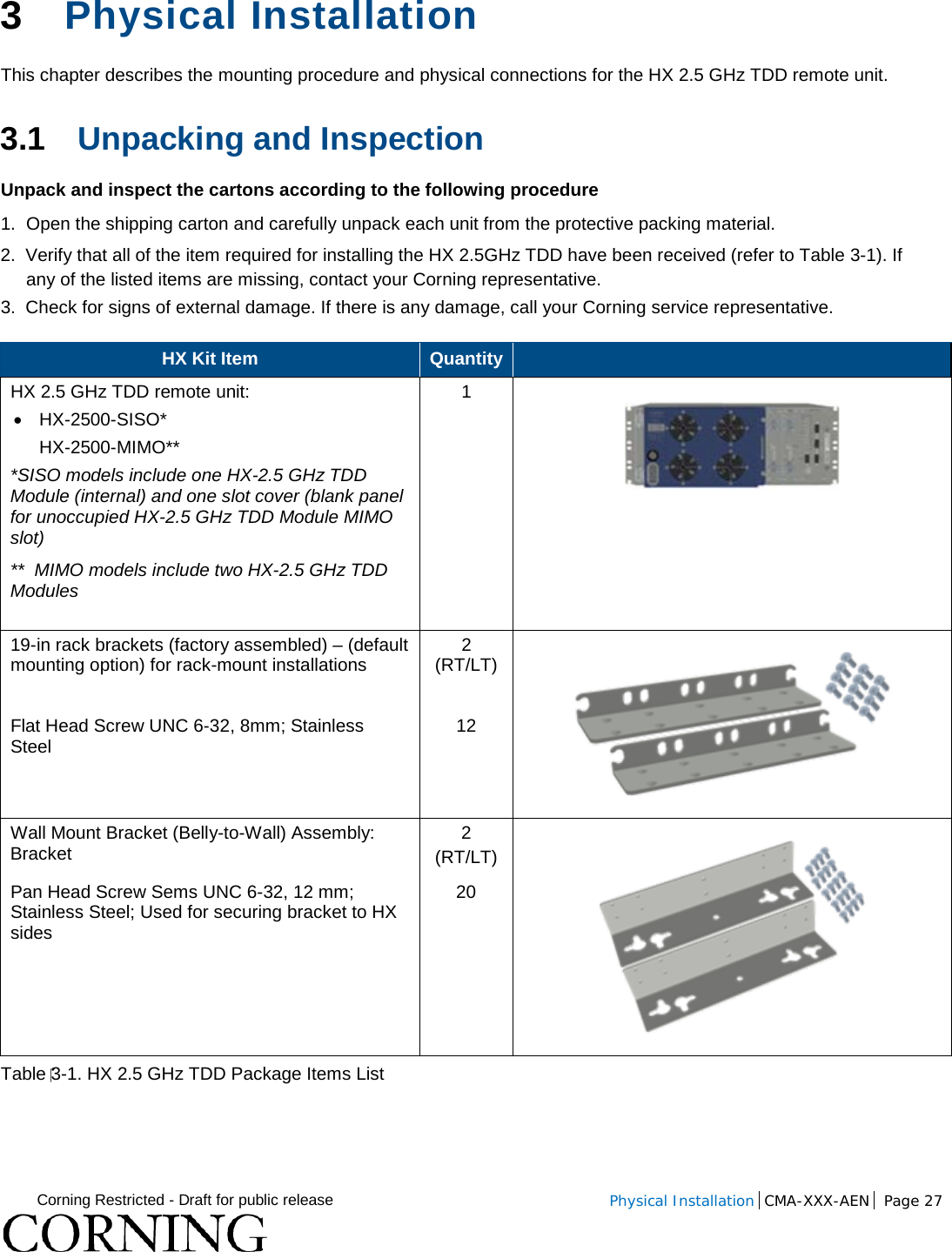
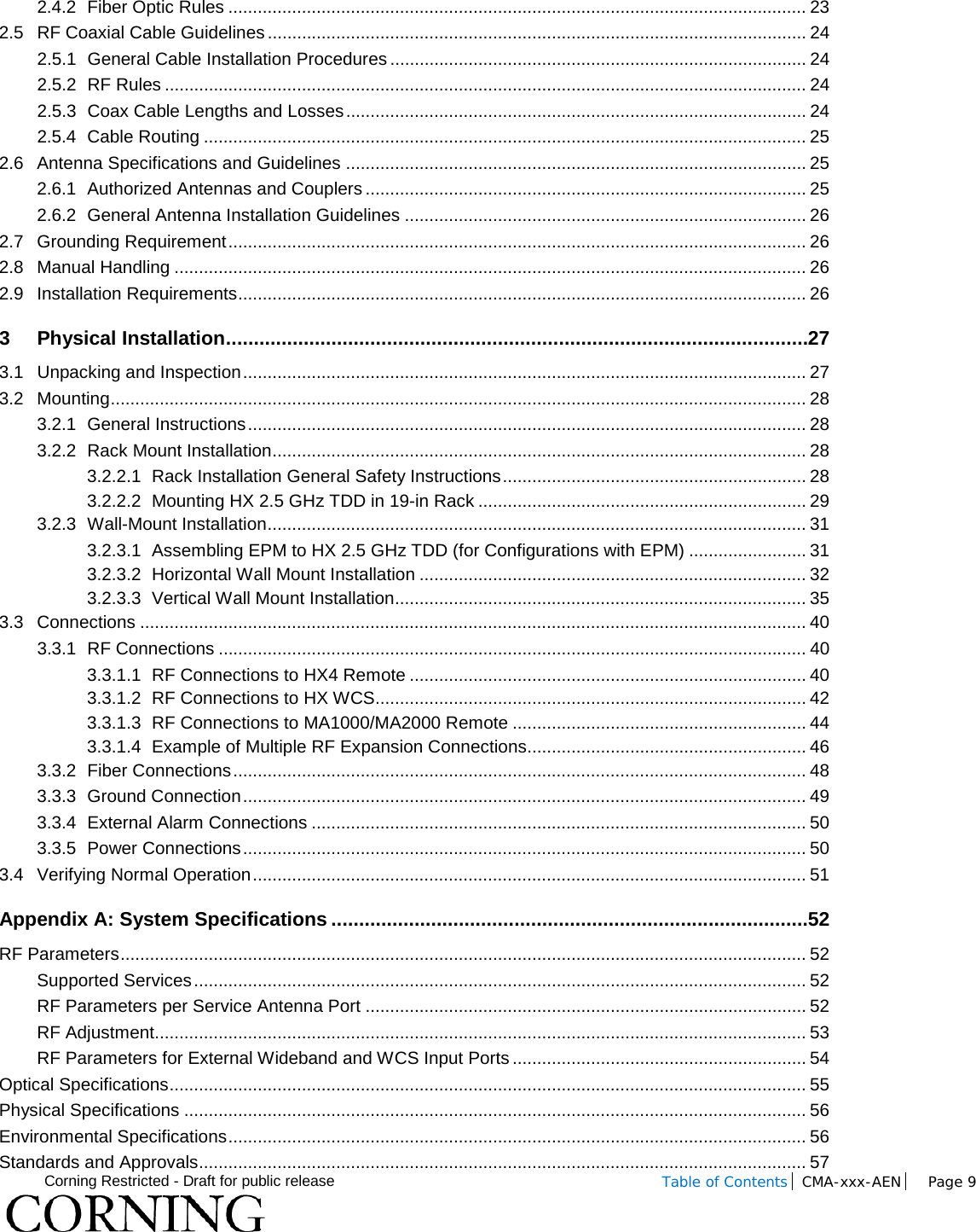
![Corning Restricted - Draft for public release Introduction CMA-xxx-AEN Page 18 Refer to Figure 1-7 and Table 1-2 for description of HX status LEDs. HX 2.5GHz TDD RCU Module Status LEDs Figure 1-7 Note: Module 1 and Module 2 LEDs correspond to installed modules [Module 1 for ANT. 1 (SISO); Module 2 for ANT. 2 (MIMO)]. LED State Description Run Steady green Off Power input detected Unit power is off Comm Green Short blink upon receiving FSK message(Off at any other time) Link Steady green Optical link level is above normal threshold Blinking green Optical link level is lower than normal threshold but above no-link threshold Off Optical link level is below No link threshold Status Green / Yellow / Red Color according to device’s overall status Service Green Service status is ok Red Any service alarm is set Ant. Green VSWR alarm is clear Red VSWR alarm is set Temp. Green Over Temp and Temperature Protection alarms are clear Red Over Temp or Temperature Protection alarms is set T-Sync Green TDD sync locked Red TDD sync error (unlocked) Fan Green Fan alarm is clear Yellow Fan alarm is set (minor) for first fan faulty Red Fan alarm is set (minor or major) for more than one faulty fan Table 1-2. HX 2.5GHz TDD RCU Status LED Descriptions](https://usermanual.wiki/Corning-Optical-Communication/HX-2500-SISO/User-Guide-2909458-Page-18.png)