Corning Optical Communication HXP19S80A17L70 Mid Power Remote Unit - HX-5 (BOOSTER) User Manual DAS System
Corning Optical Communication Wireless Mid Power Remote Unit - HX-5 (BOOSTER) DAS System
UserManual.wiki
>
Corning Optical Communication
>
HXP19S80A17L70 User Manual
>
Users Manual
Contents
1.
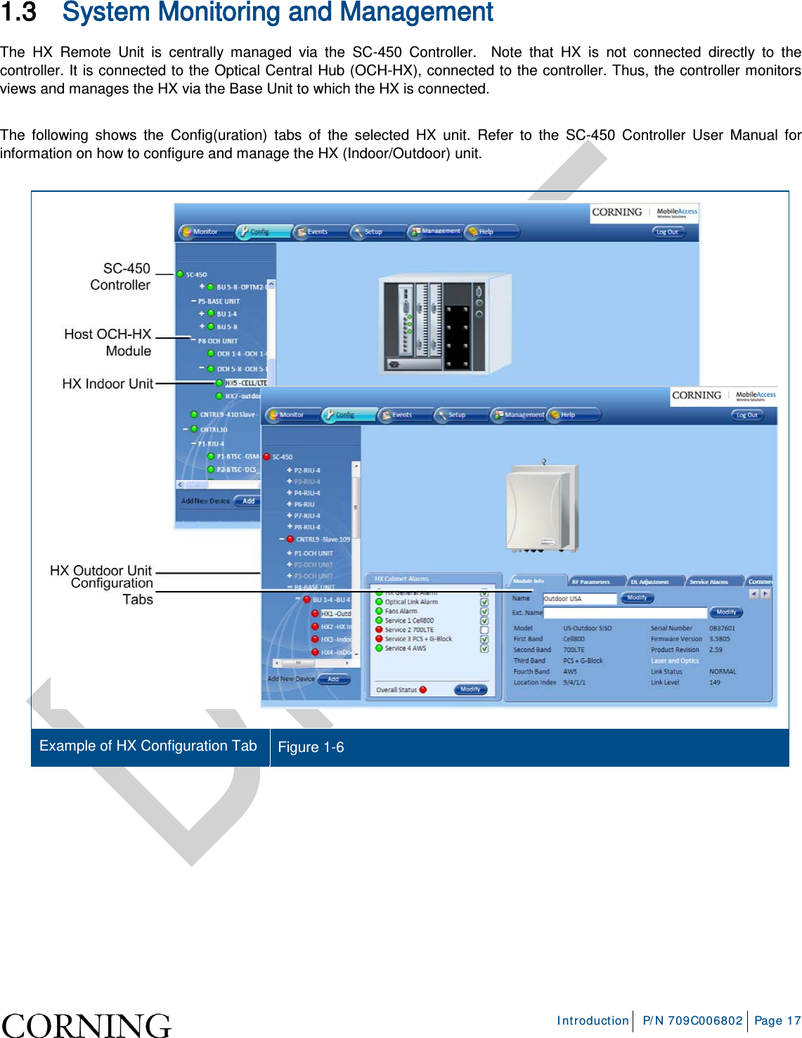
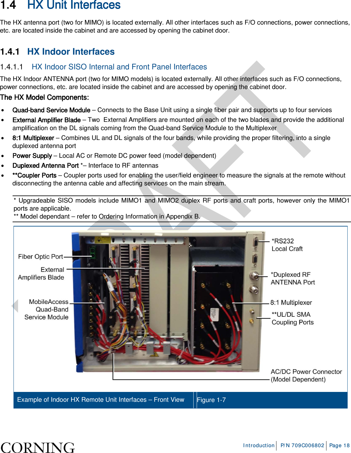
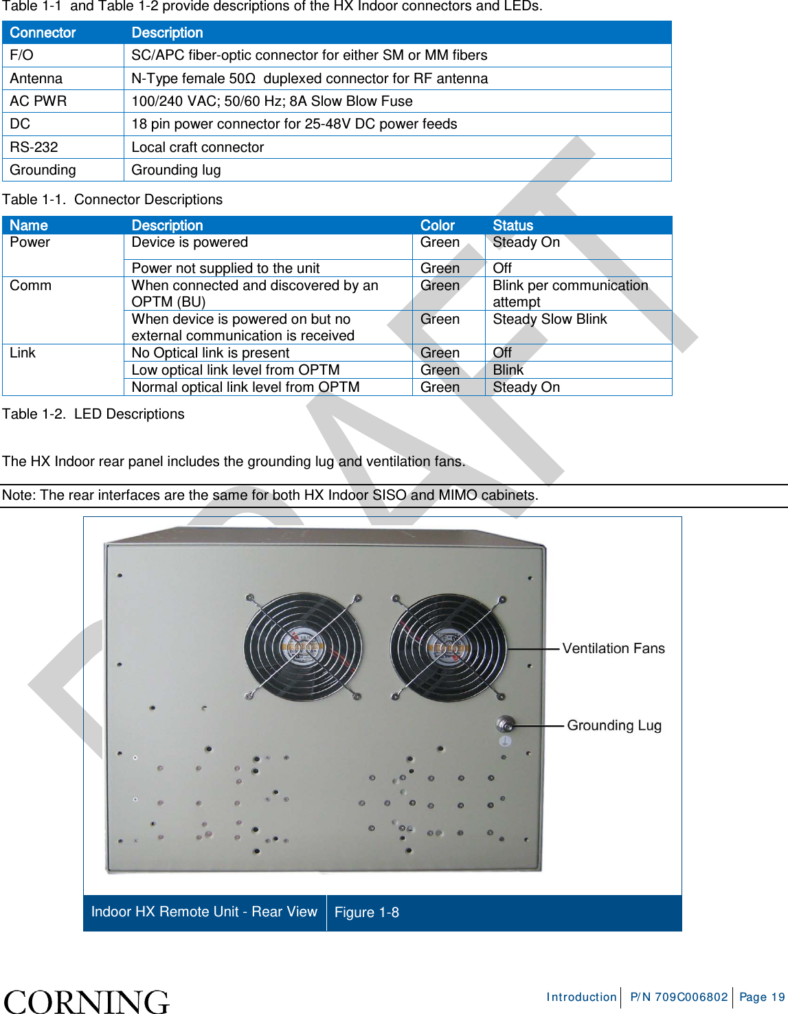
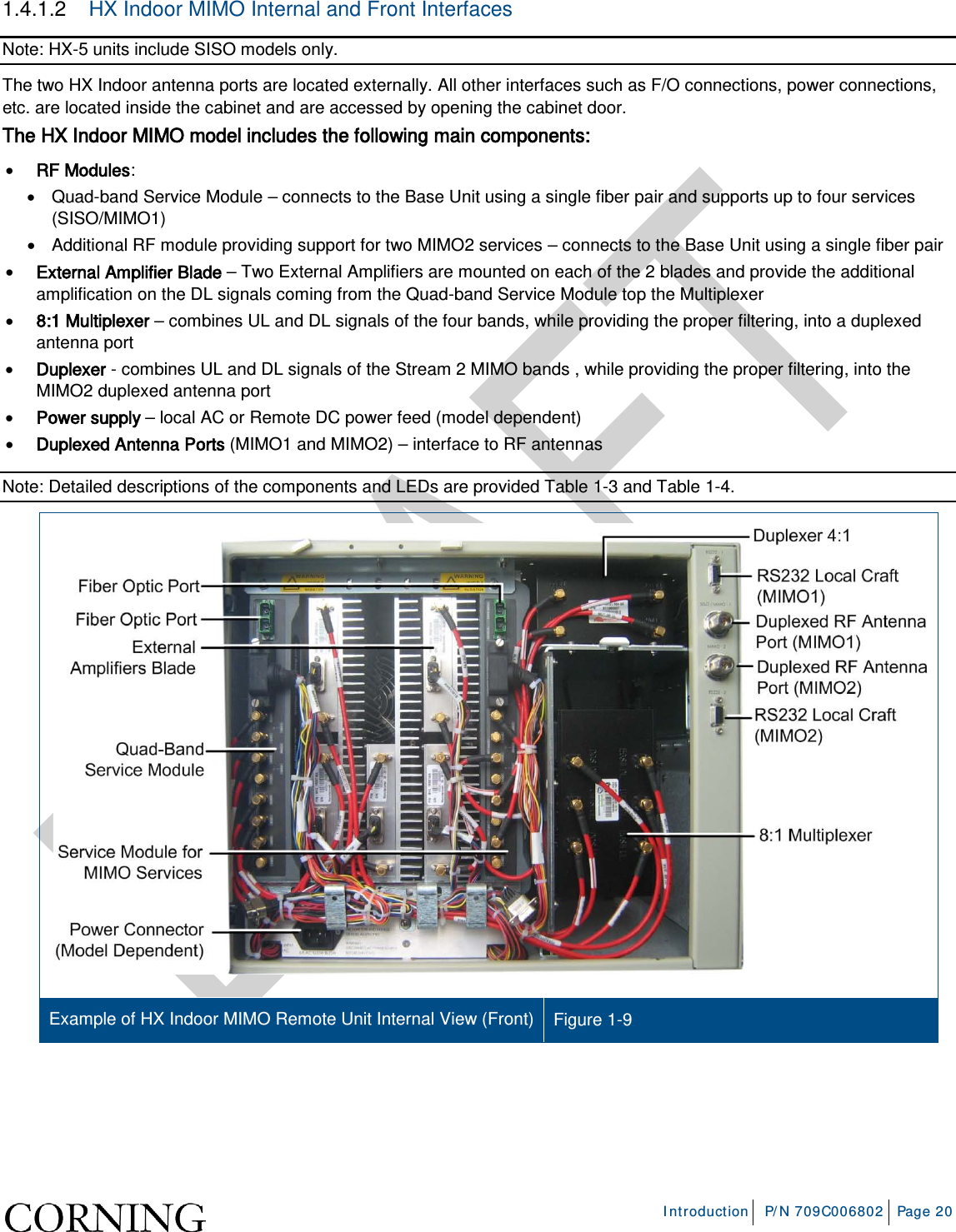
Users Manual
2.
User Manual
Users Manual
Navigation menu
Upload a User Manual
Namespaces
Wiki Guide
HTML
PDF
Info
Views
User Manual
Discussion / Help
Navigation