Corning Optical Communication LITENNA0LF0SB0 In Building Repeater User Manual Litenna Installation Guide
Corning Optical Communication Wireless In Building Repeater Litenna Installation Guide
Contents
- 1. Litenna Installation Guide
- 2. Litenna Data Sheet
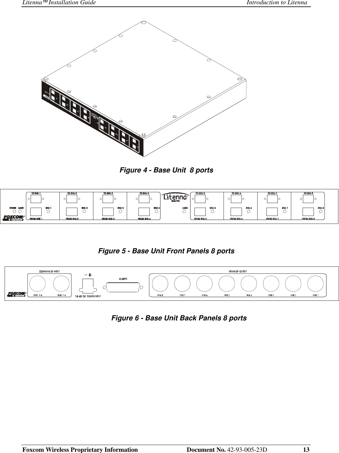
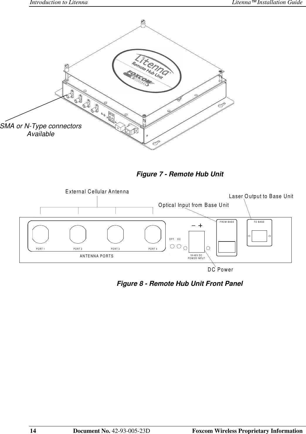
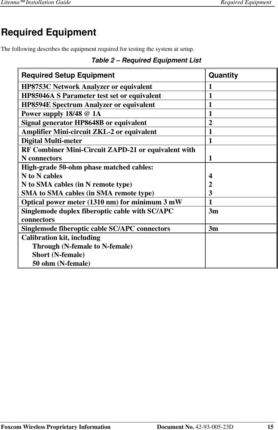
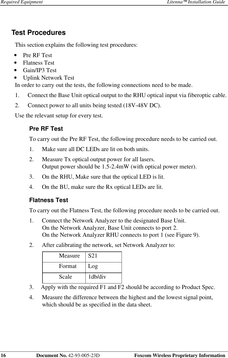
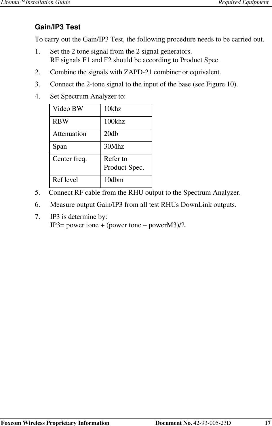
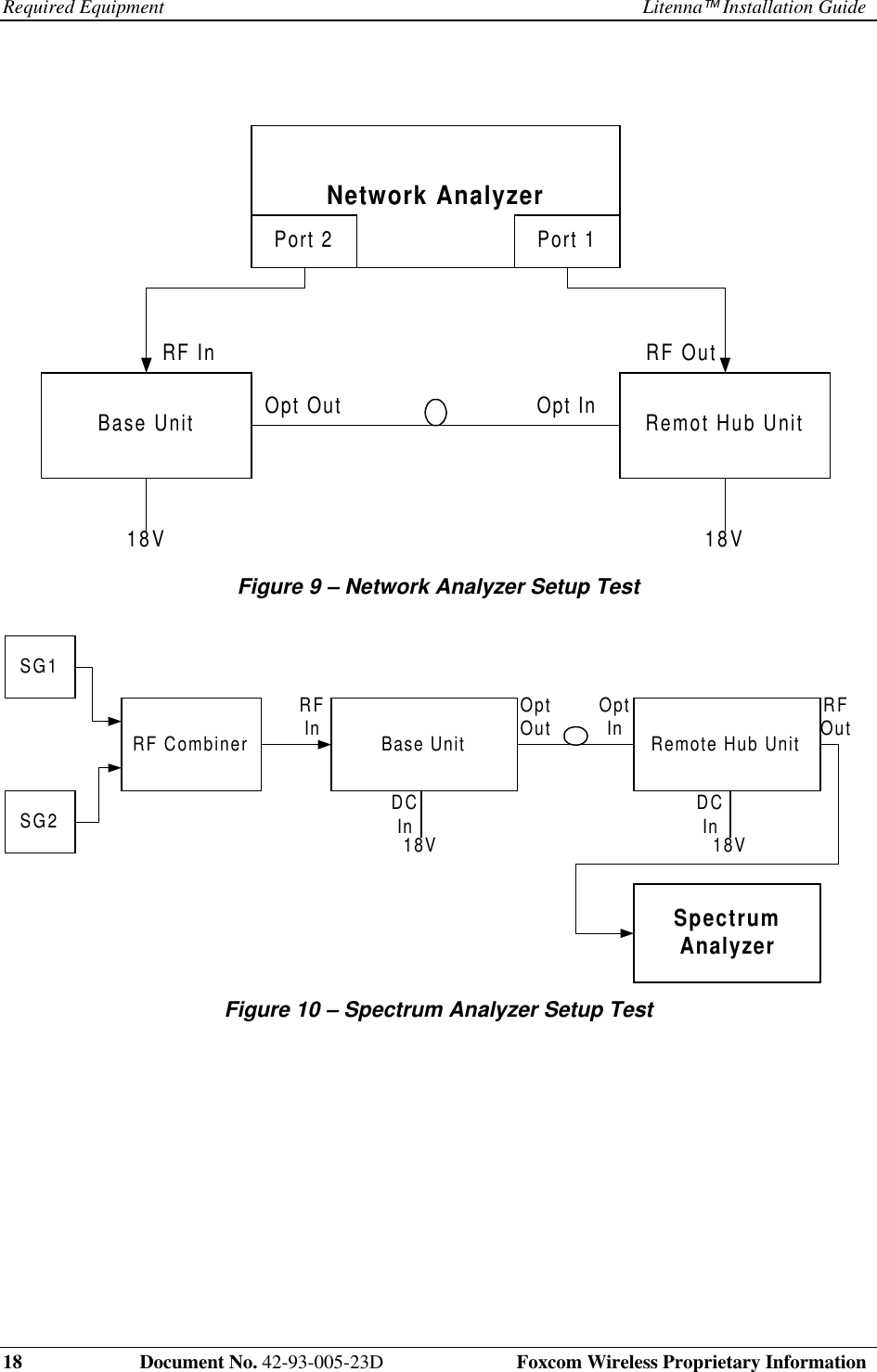
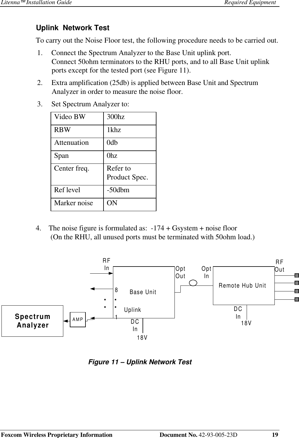
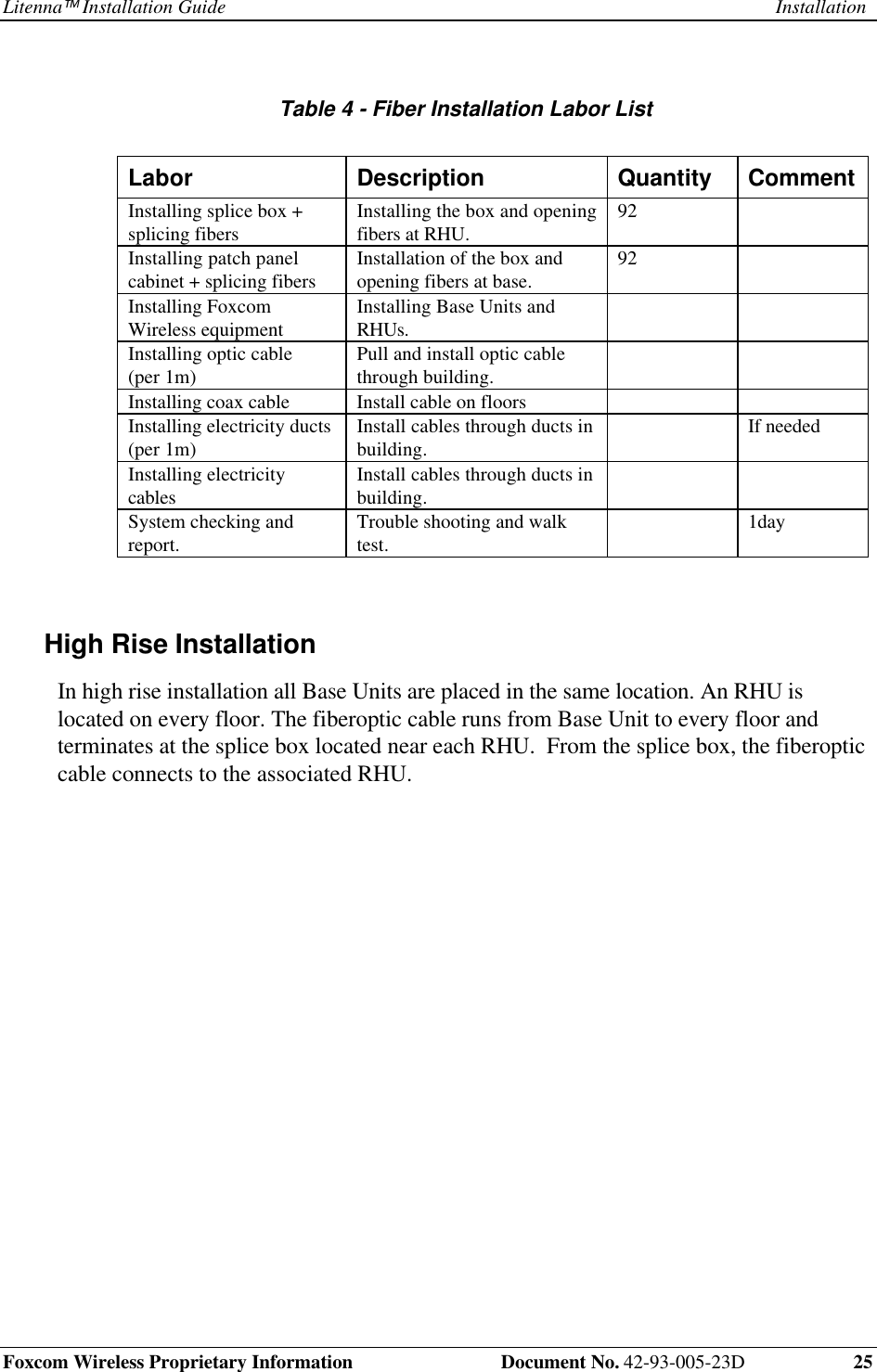
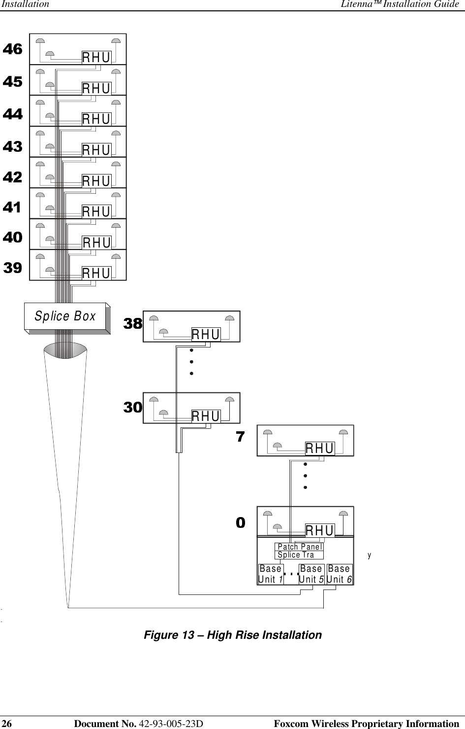
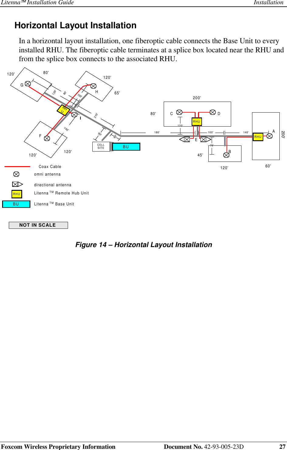
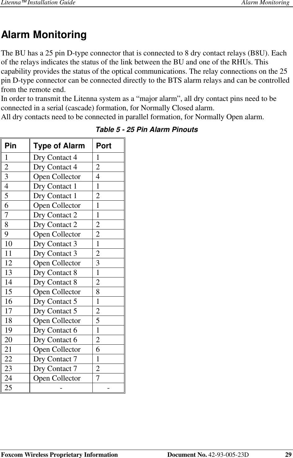
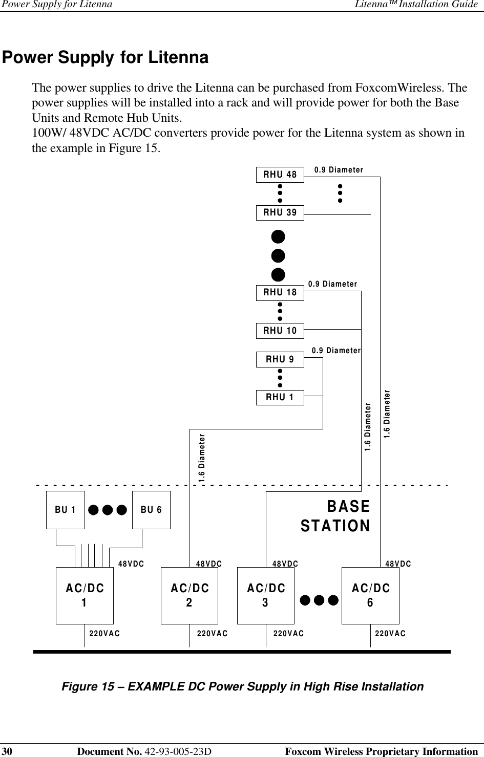
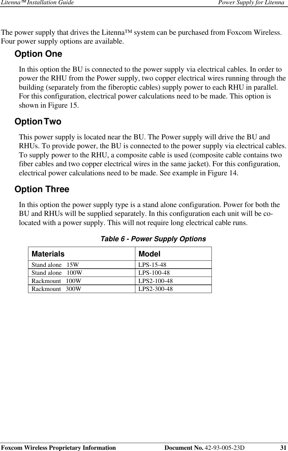
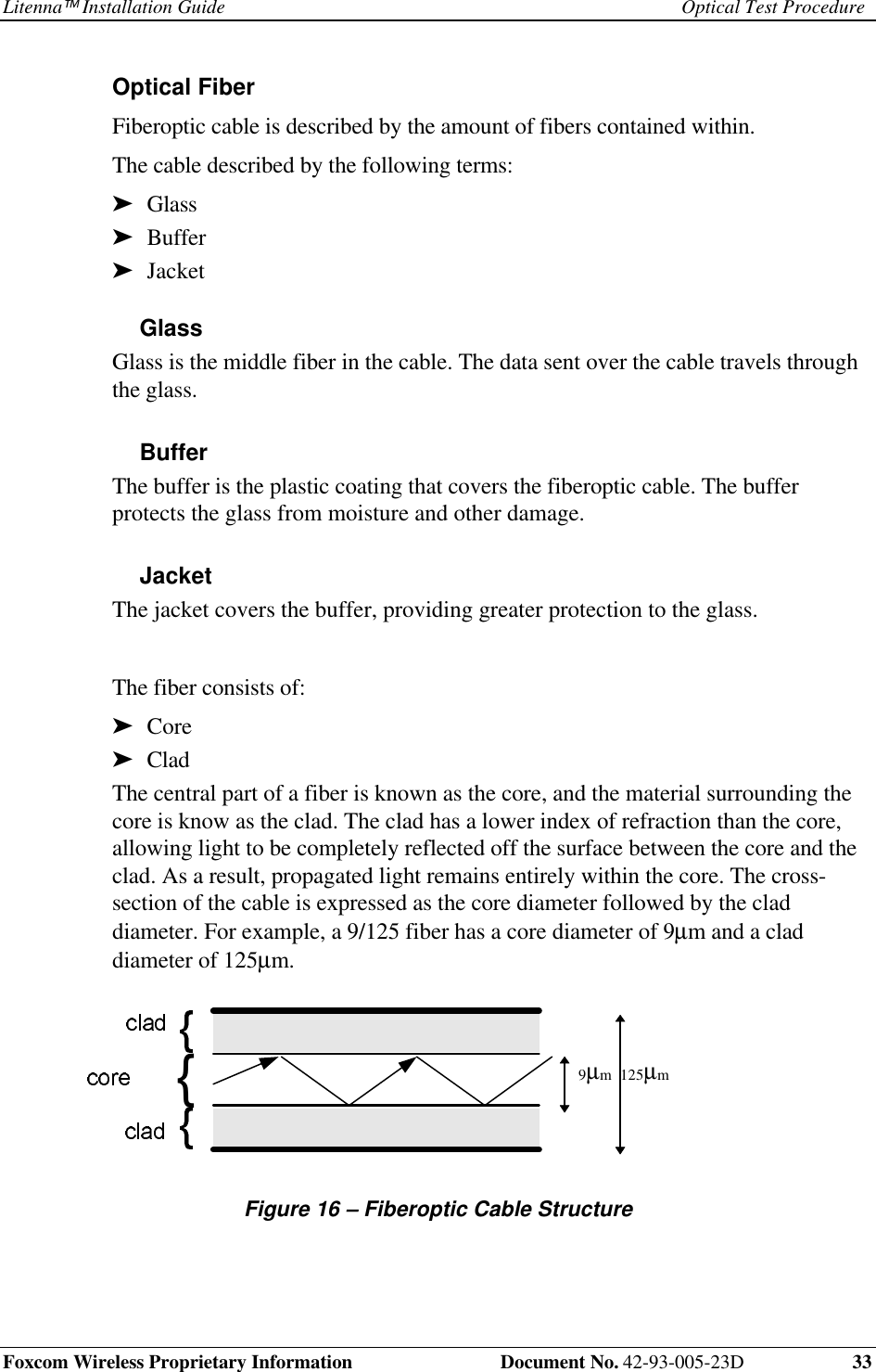
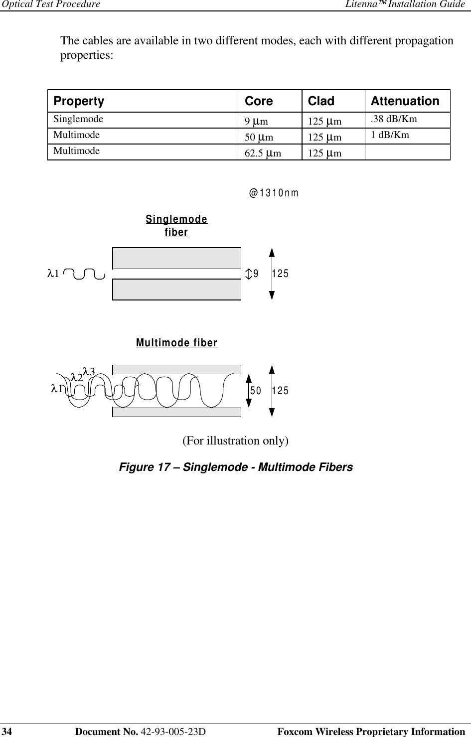
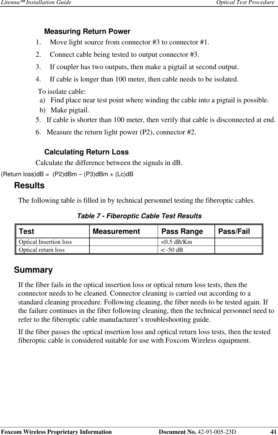
Litenna Installation Guide