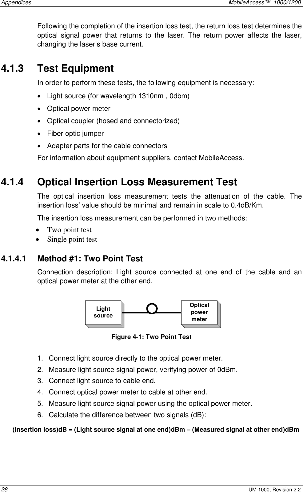
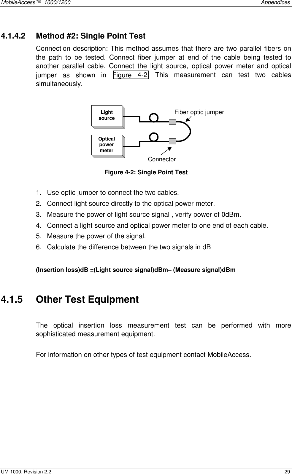
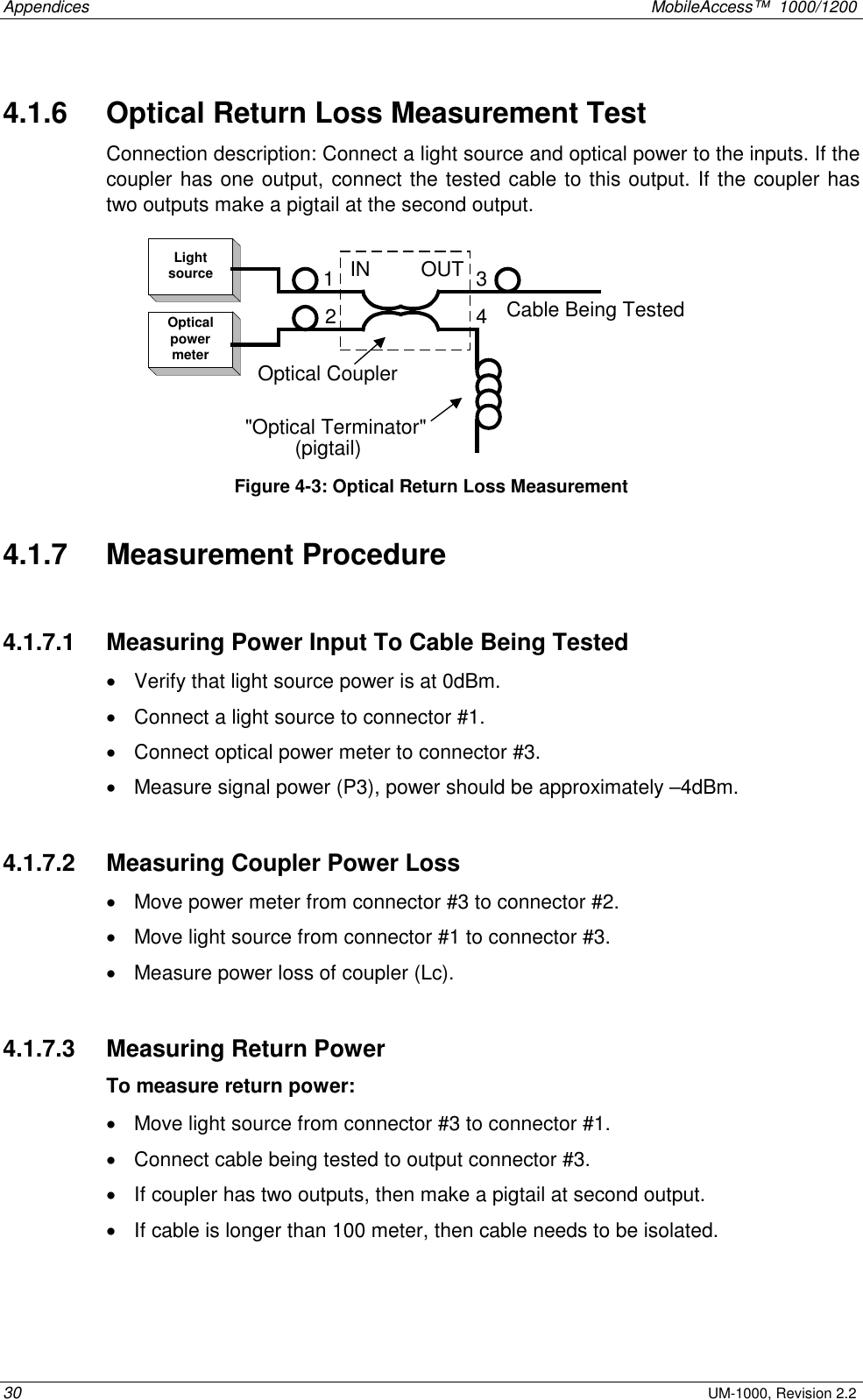
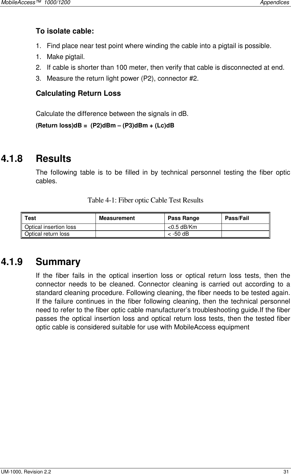
Corning Optical Communication MA1200 Mobile Telephone In-Building Distribution System User Manual MobileAccess 1000 1200 Installation Guide
Corning Optical Communication Wireless Mobile Telephone In-Building Distribution System MobileAccess 1000 1200 Installation Guide
Contents
- 1. User Manual
- 2. users manual
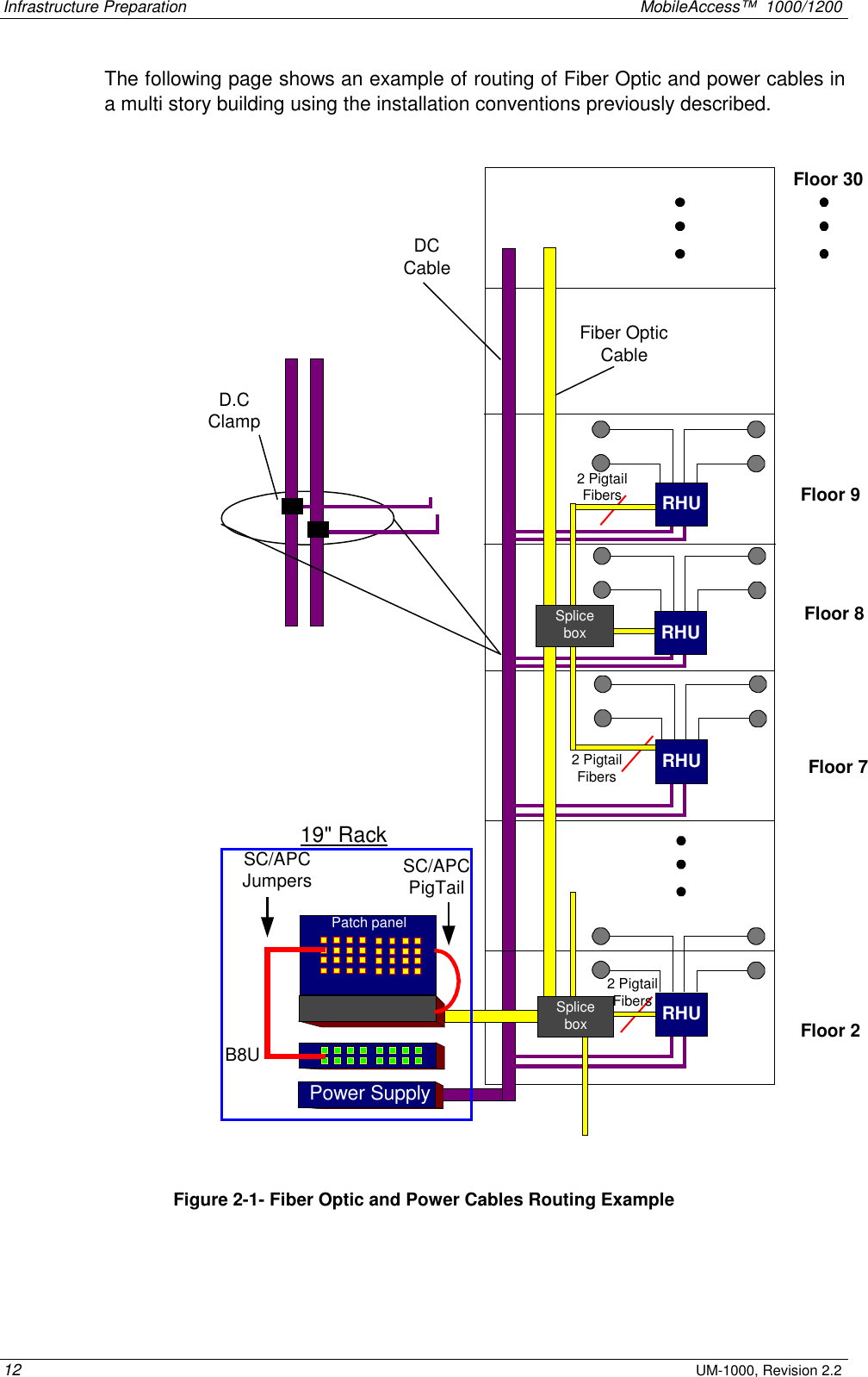
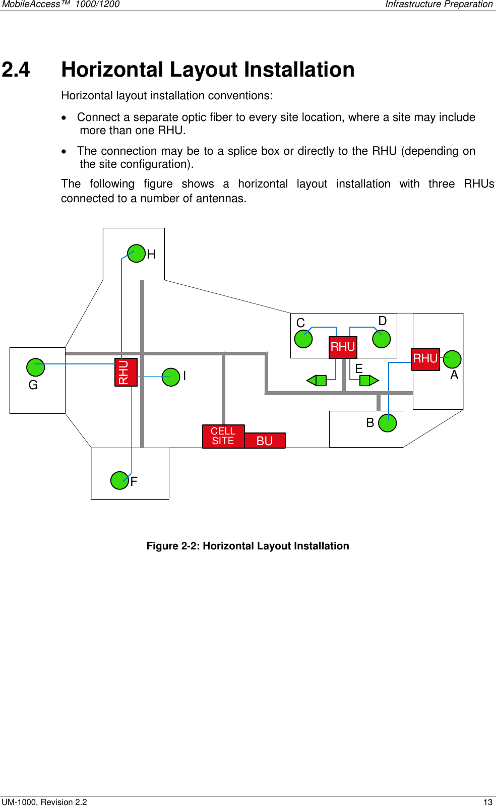
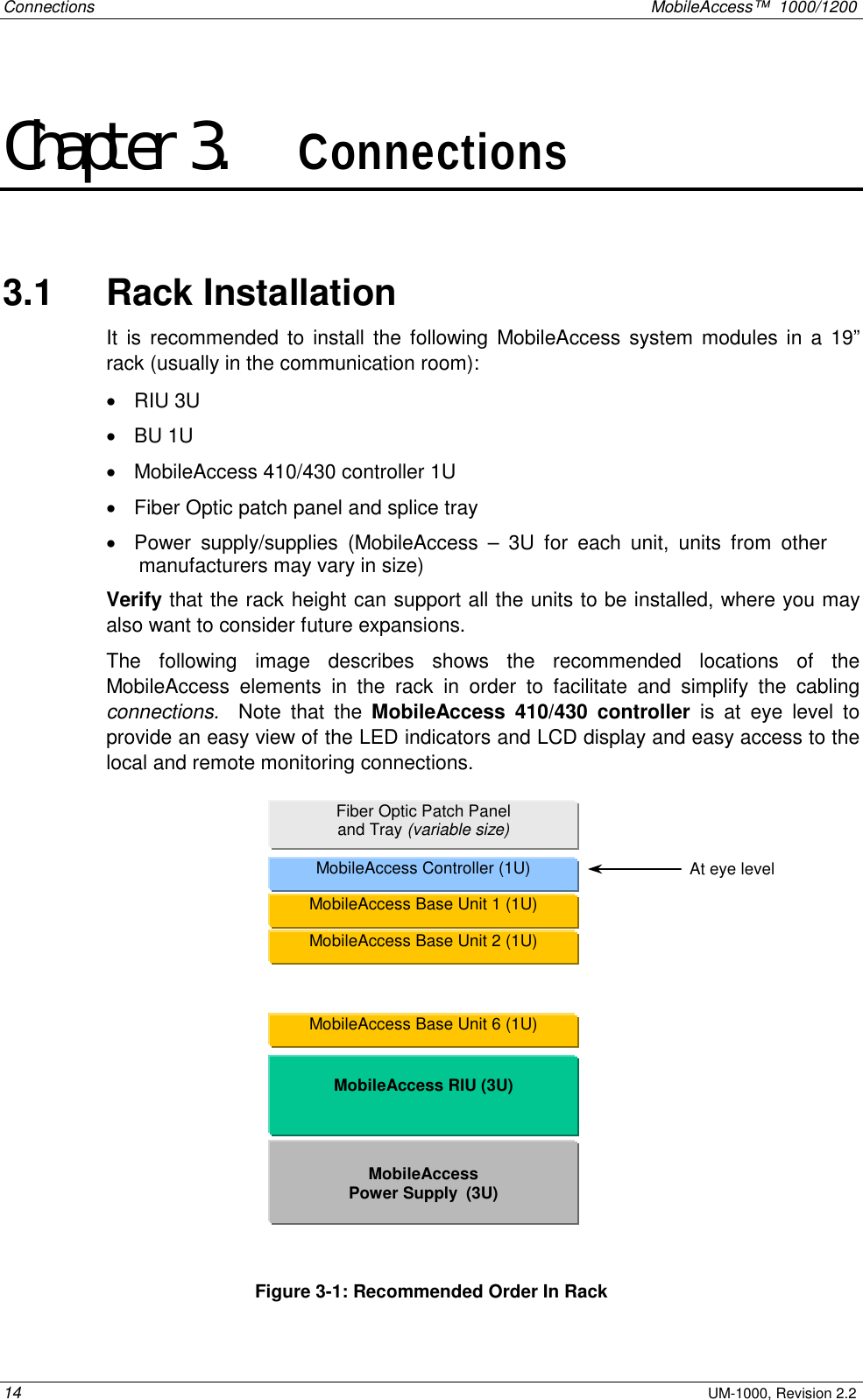
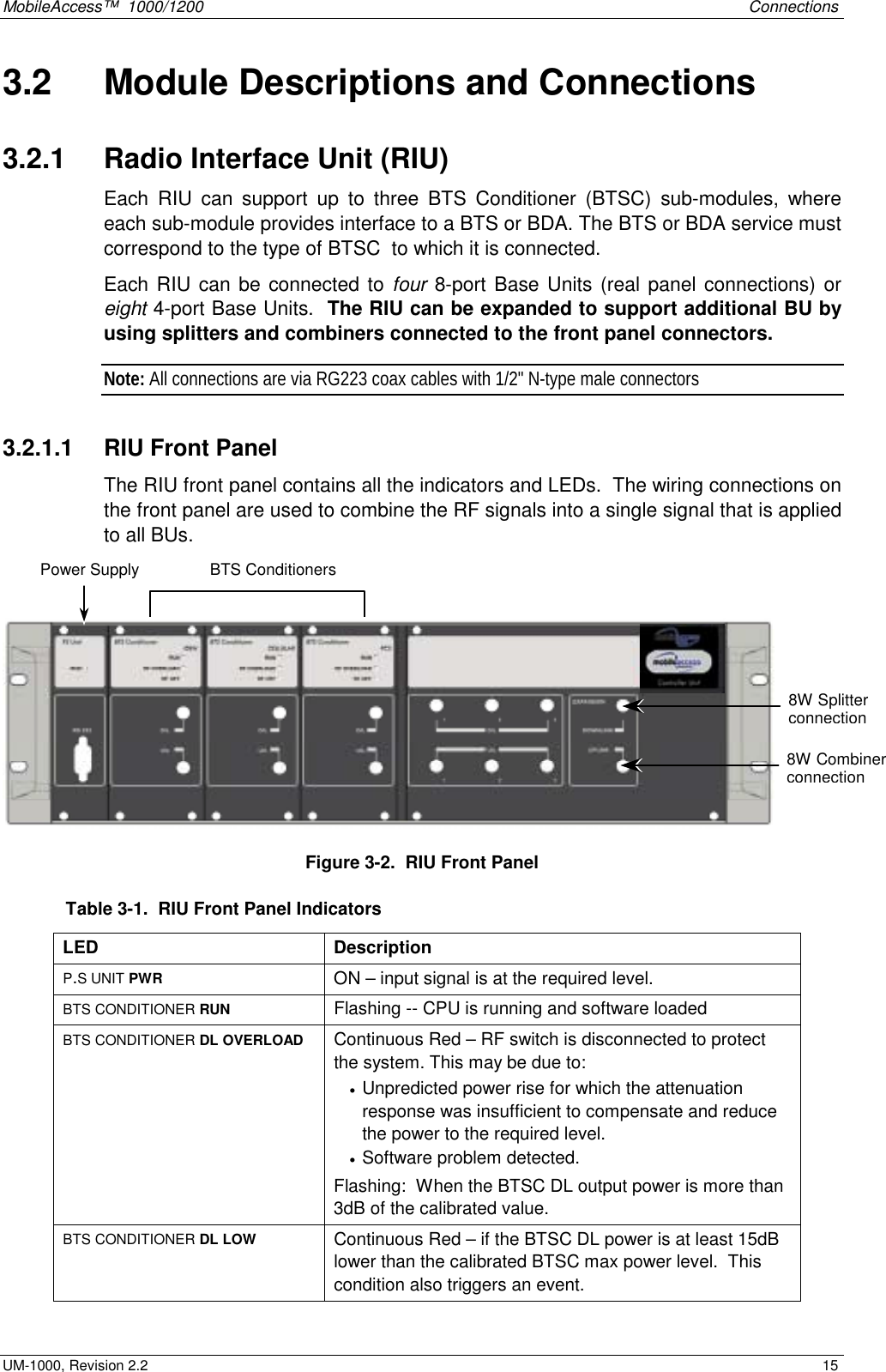
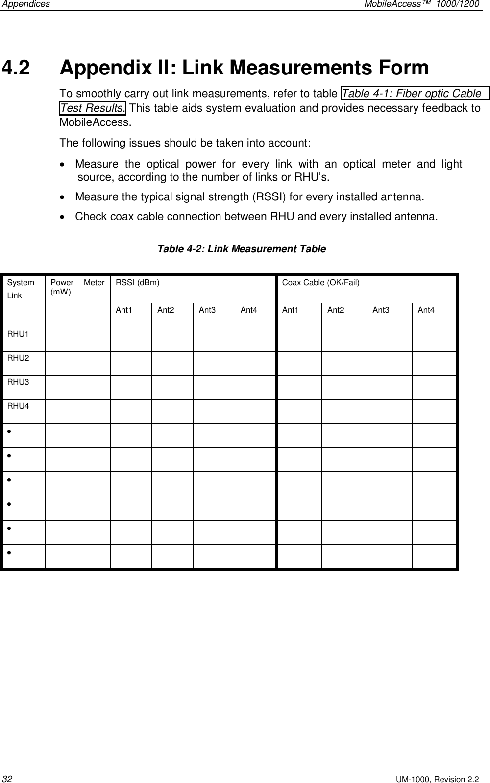
User Manual