Corning Optical Communication MA1200G Mobile Telephone In-Building Distribution System User Manual
Corning Optical Communication Wireless Mobile Telephone In-Building Distribution System
UserManual.wiki
>
Corning Optical Communication
>
MA1200G User Manual
>
User Manual
Contents
1.
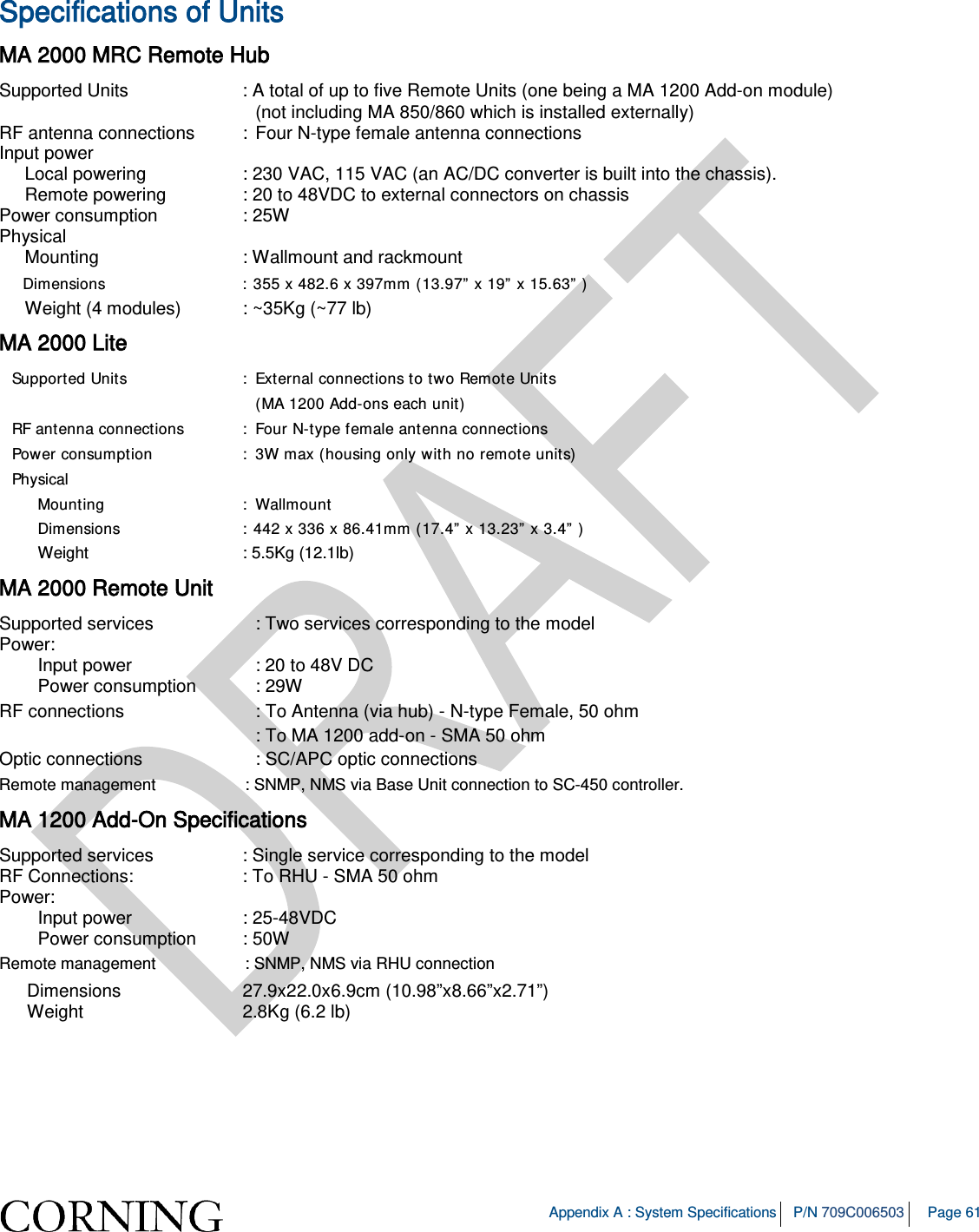
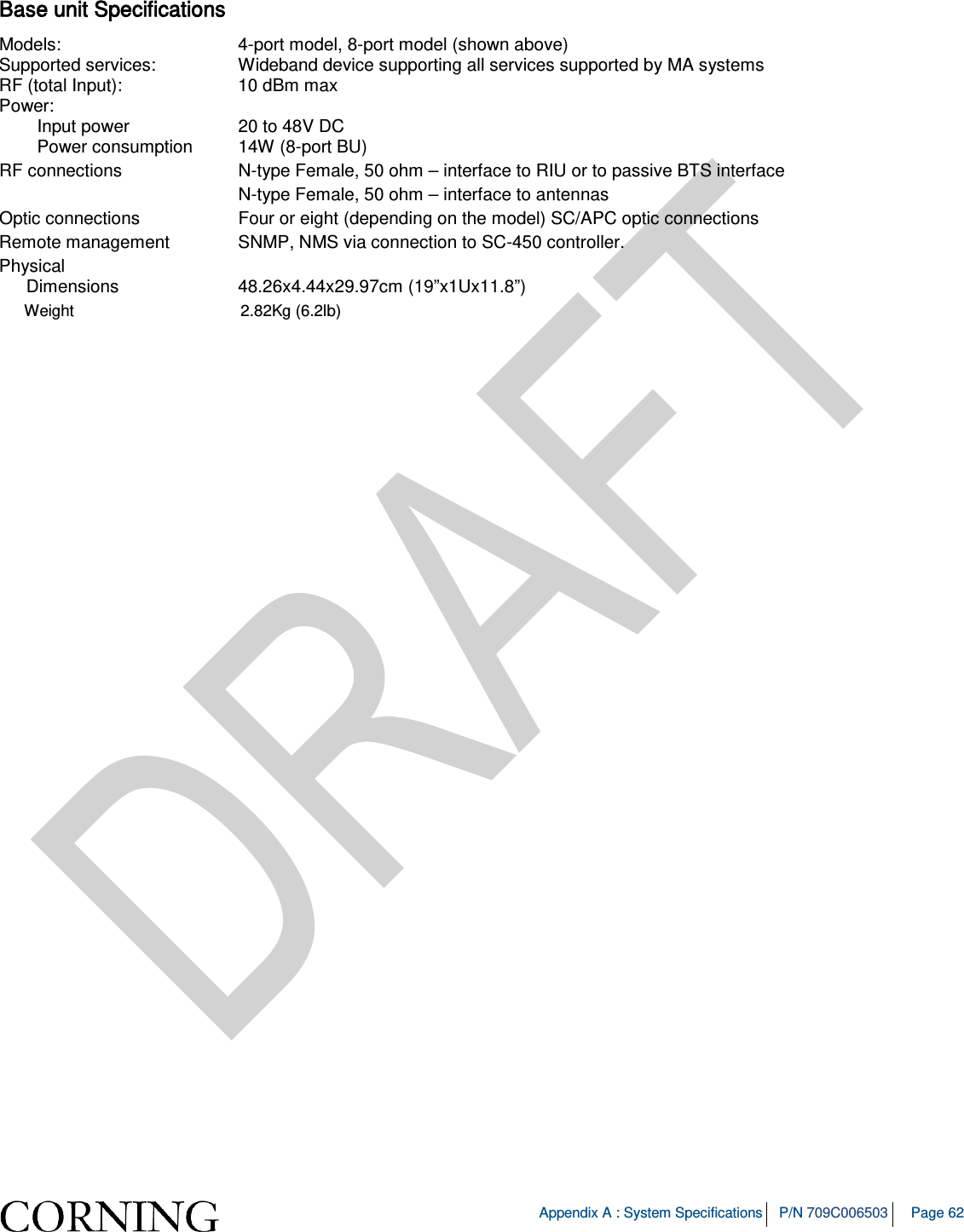
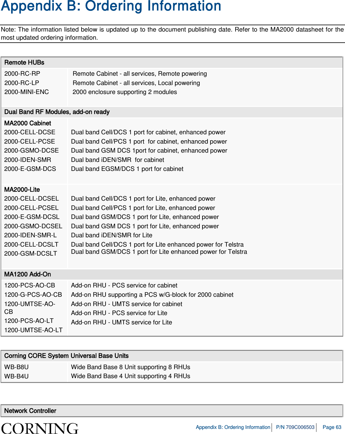
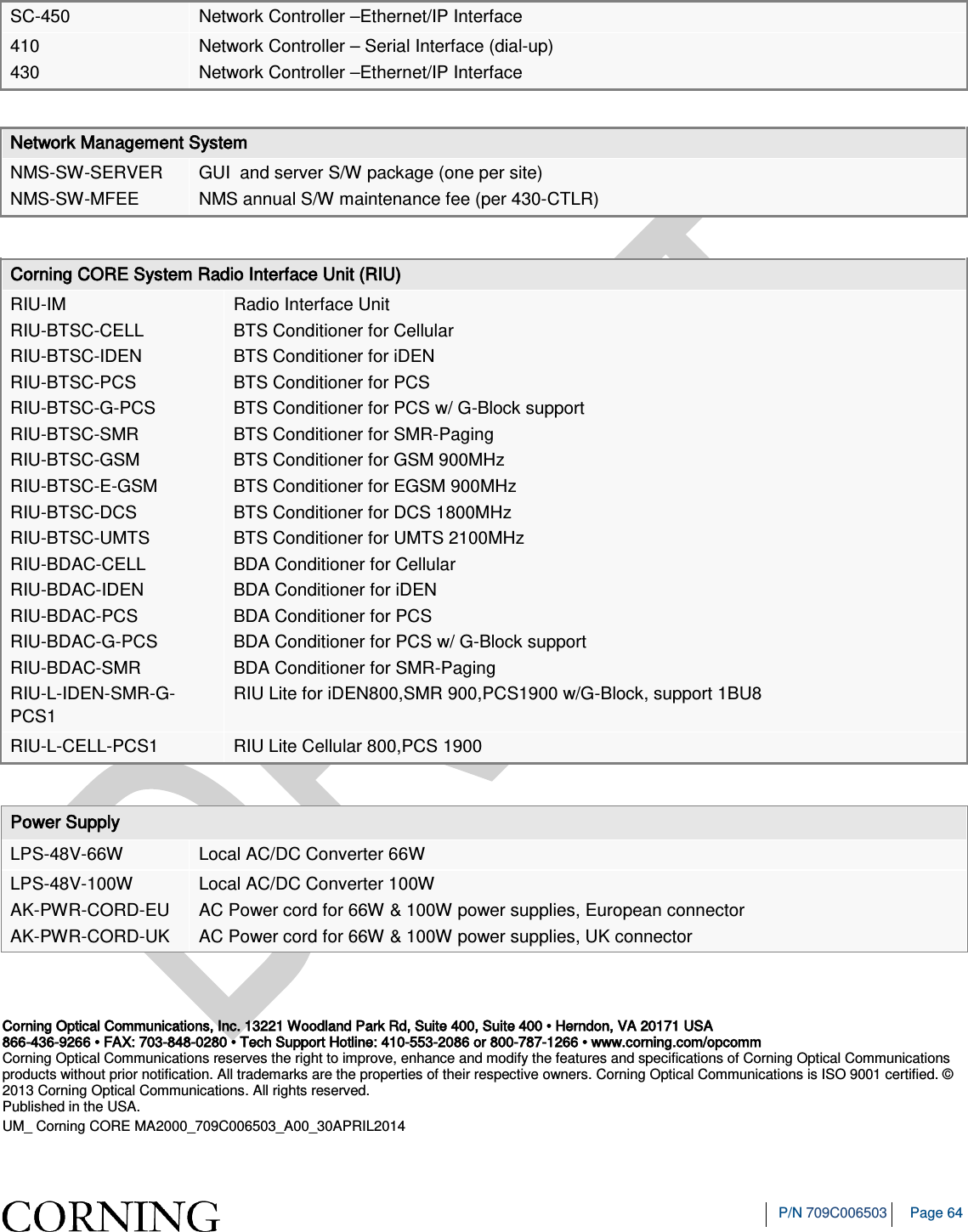
USERS MANUAL
2.
User Manual
User Manual
Navigation menu
Upload a User Manual
Namespaces
Wiki Guide
HTML
PDF
Info
Views
User Manual
Discussion / Help
Navigation