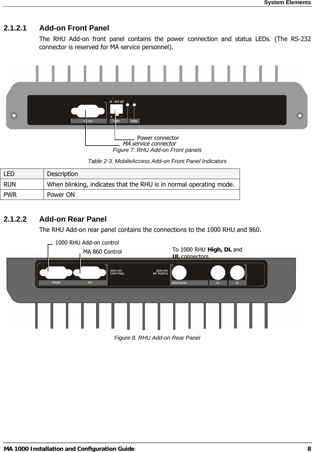
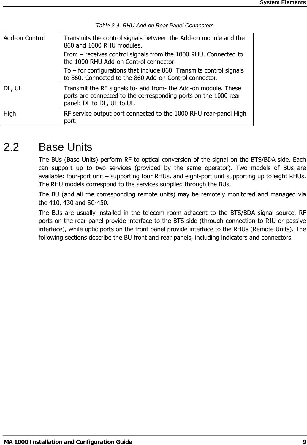
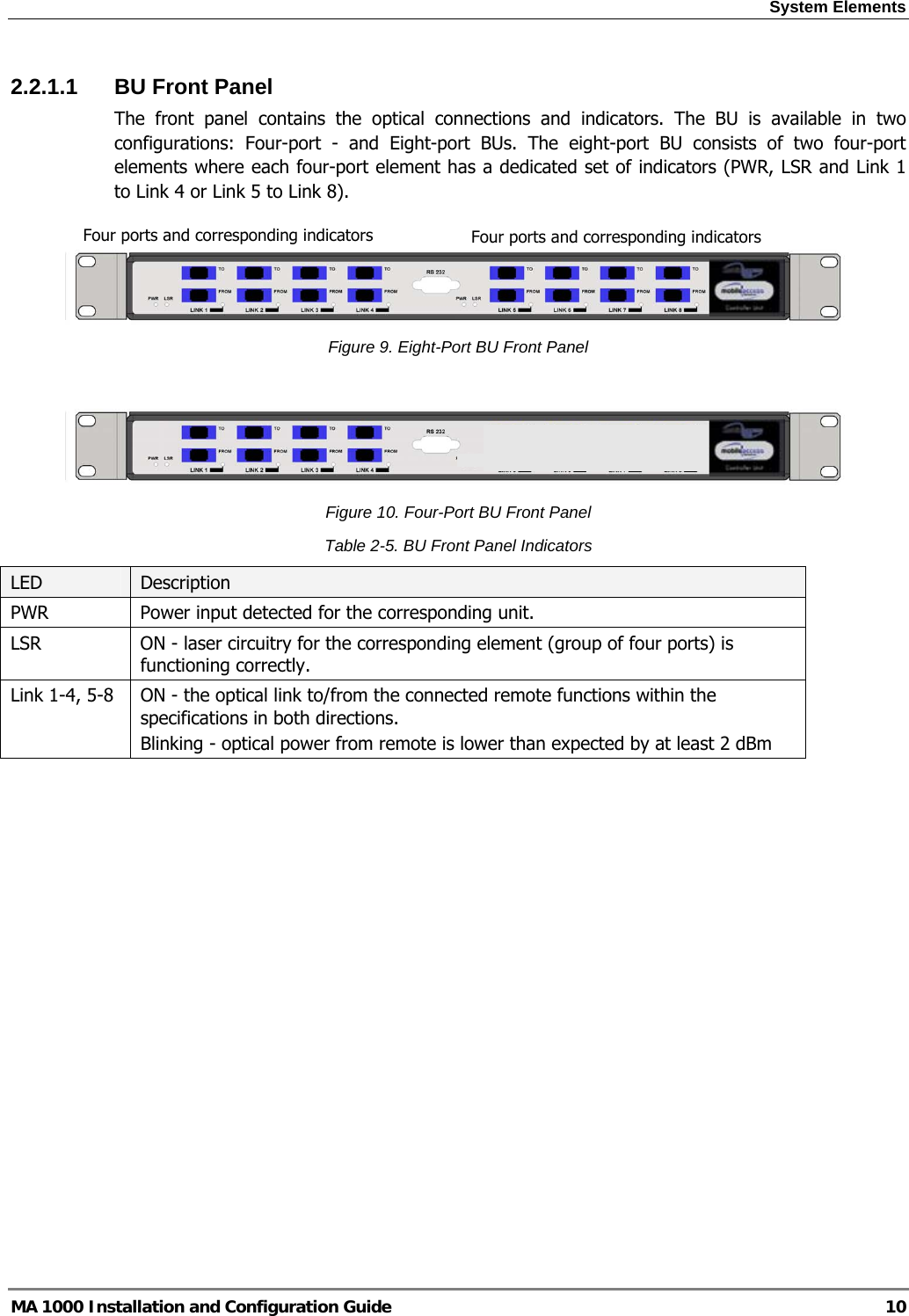
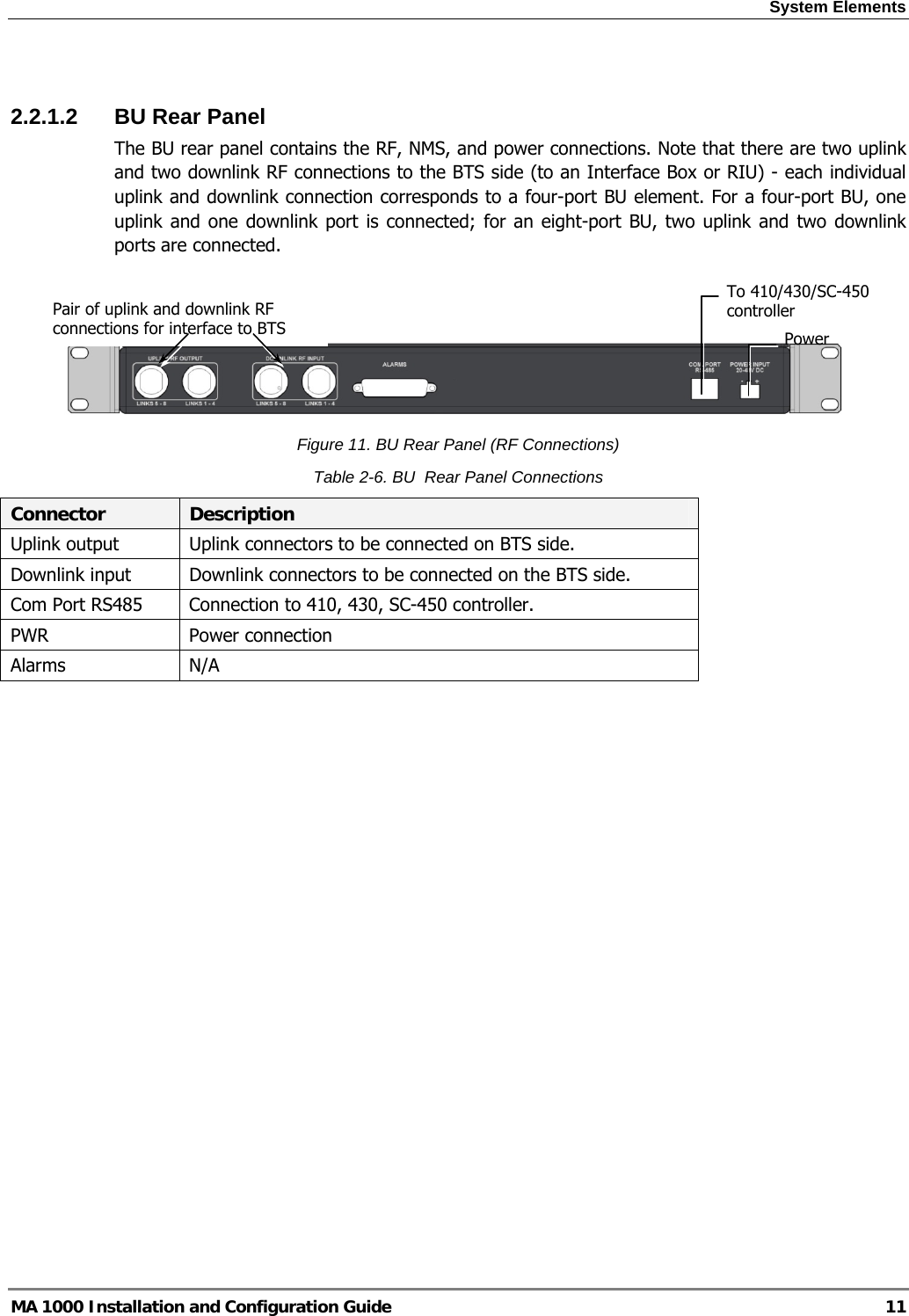
Corning Optical Communication MA1200LTE700 ADD-ON LTE User Manual
Corning Optical Communication Wireless ADD-ON LTE Users Manual
UserManual.wiki
>
Corning Optical Communication
>
MA1200LTE700 User Manual
Users Manual
Navigation menu
Upload a User Manual
Namespaces
Wiki Guide
HTML
PDF
Info
Views
User Manual
Discussion / Help
Navigation
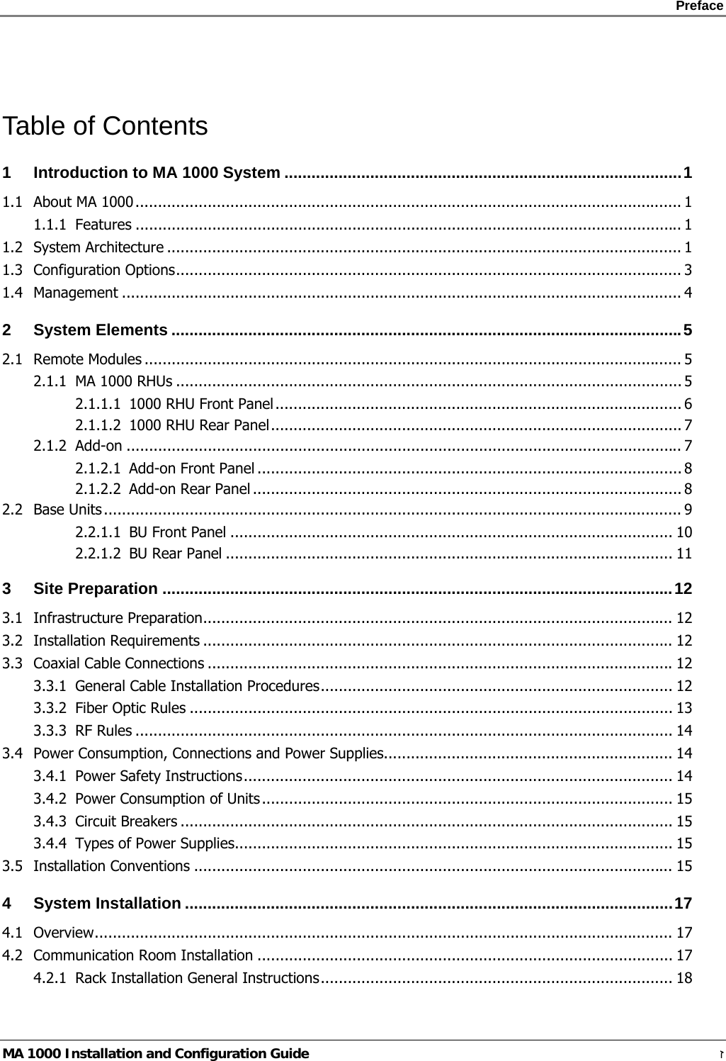
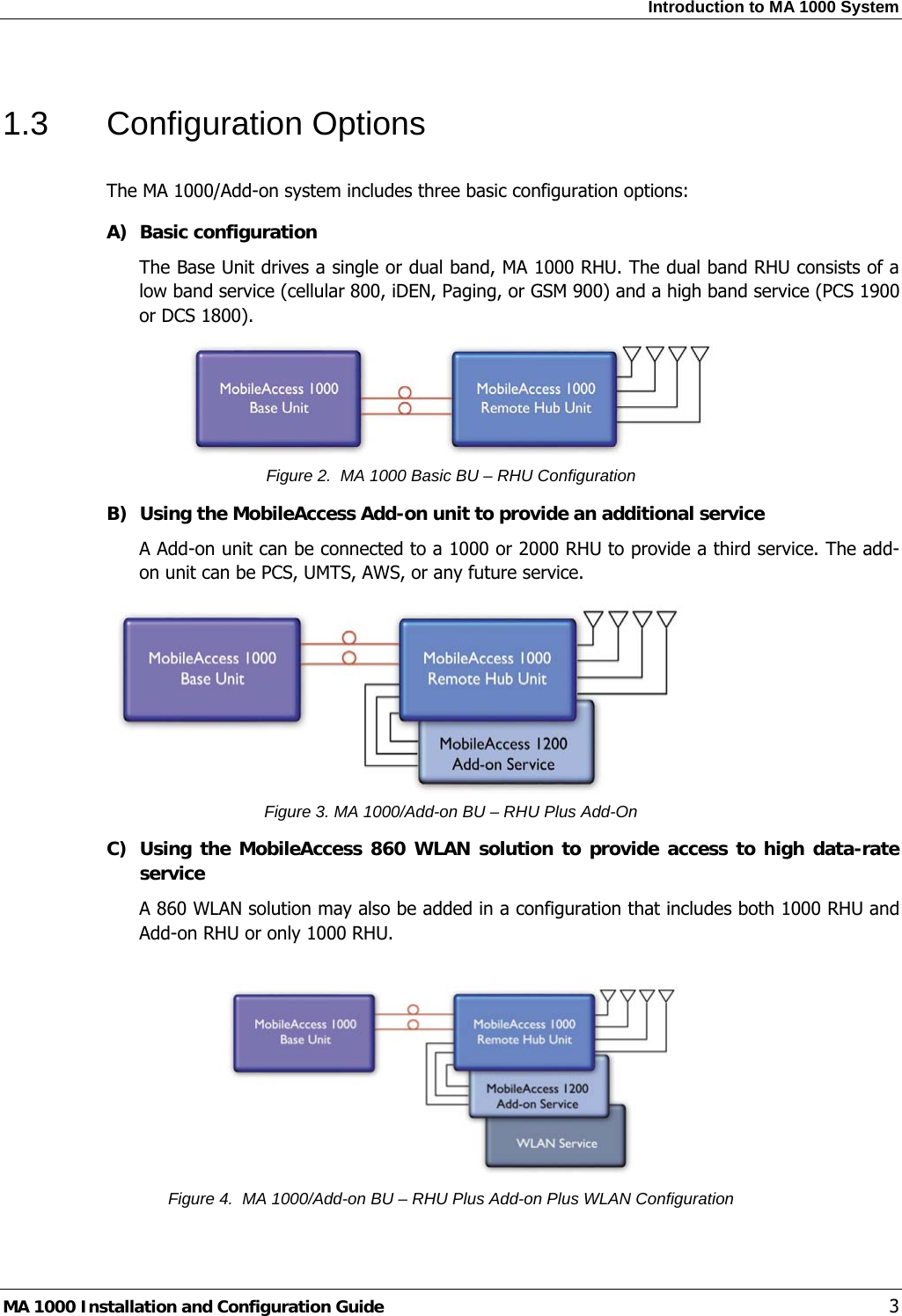
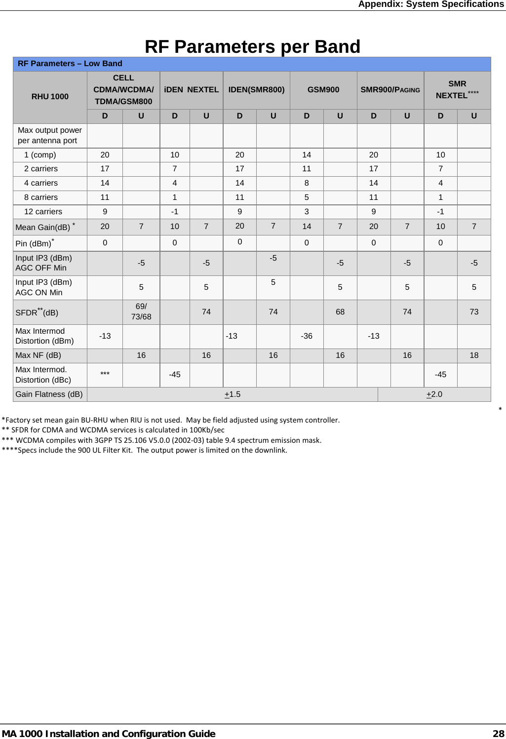
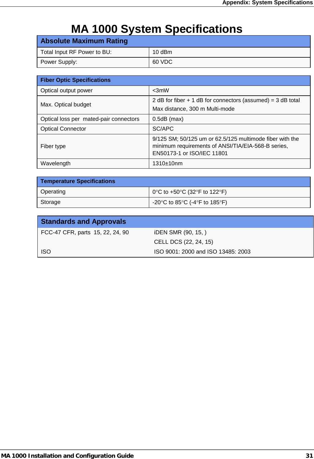
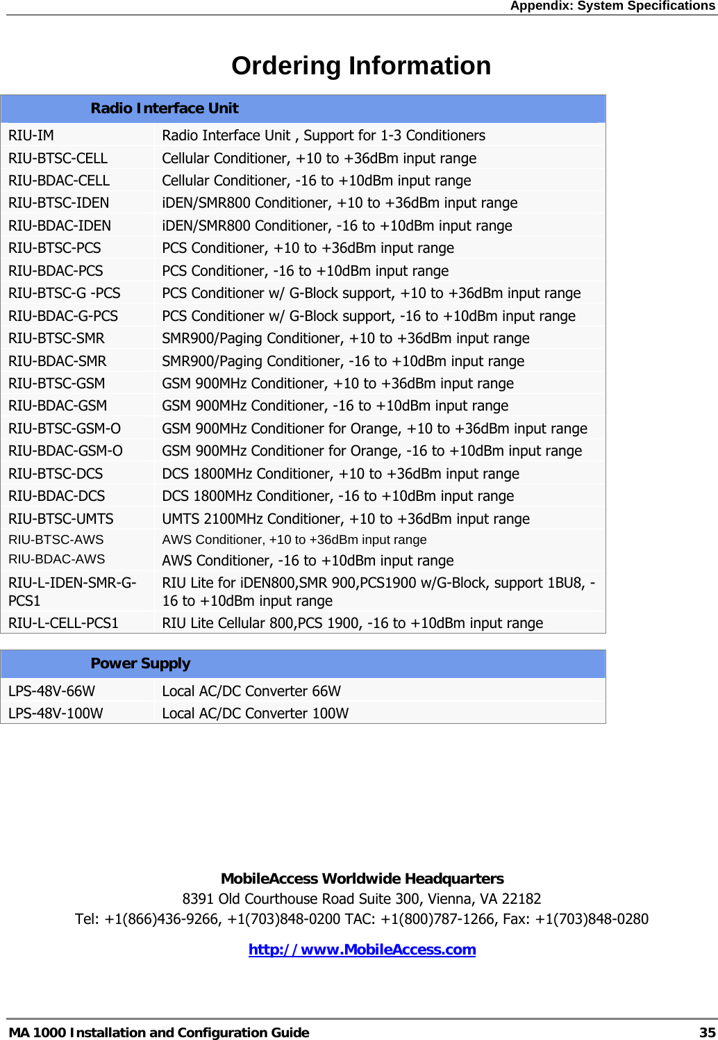
![Appendix: System Specifications MA 1000 Installation and Configuration Guide 30 1200 Add-on RF Parameters per Band 1200 Add-on G-PCS CDMA/WCDMA G-PCS GSM/TDMA UMTS and AWS CDMA/WCDMA LTE 700MHz Max output power per antenna port D U D U D U D U 1(composite) 20 21 21 21 2 carriers 17 18 18 18 4 carriers 14 15 15 15 8 carriers 11 12 12 12 12 carriers 9 10 10 Mean Gain(dB)1 20 3 20 3 21 3 21 Pin (dBm)1 0 1 0 0 Max. Intermodulation Distortion [dBm] -13/* -13 * ** Input IP3 (dBm) -7 -7 -7 -7 SFDR (dBm)2 66 64 66 55 Max NF (dB) 18 18 18 18 Gain Flatness (dB)3 +2.0 +1.04 * WCDMA compiles with 3GPP TS 25.106 V5.0.0 (2002-03) table 9.4 spectrum emission mask ** Out of band and spurious emissions compliant to FCC 1 Factory set mean gain BU-RHU when RIU is not used. May be field adjusted using system controller 2 SFDR for CDMA and WCDMA services is calculated in 100Kb/sec; LTE is calculated for 10MHz channel 3 Gain Ripple is specified for non duplexed port of the system. 4 Gain Ripple at any block](https://usermanual.wiki/Corning-Optical-Communication/MA1200LTE700/User-Guide-1243170-Page-38.png)