Corning Optical Communication MA1K-CELL-PCSE RF Repeater User Manual Manual
Corning Optical Communication Wireless RF Repeater Manual
Contents
- 1. Manual
- 2. users manual
Manual

Installation and Configuration Guide
709C001501
UM-1000 Ver. 2.4
February, 2005
MobileAccess™ 1000 System

MA 1000 Installation and Configuration Guide
II
MobileAccess 1000
Copyright © 2006 MobileAccess.
© 2005 by MobileAccess
This document contains confidential and proprietary information of MobileAccess and may
not be copied, transmitted, stored in a retrieval system or reproduced in any format or
media, in whole or in part, without the prior written consent of MobileAccess. Information
contained in this document supersedes any previous manuals, guides, specifications, data
sheets or other information that may have been provided or made available to the user.
This document is provided for informational purposes only, and MobileAccess does not
warrant or guarantee the accuracy, adequacy, quality, validity, completeness or suitability
for any purpose of the information contained in this document. MobileAccess reserves the
right to make updates, improvements and enhancements to this document and the products
to which it relates at any time without prior notice to the user. MOBILEACCESS MAKES NO
WARRANTIES, EXPRESS OR IMPLIED, INCLUDING, WITHOUT LIMITATION, THOSE OF
MERCHANTABILITY AND FITNESS FOR A PARTICULAR PURPOSE, WITH RESPECT TO THIS
DOCUMENT OR ANY INFORMATION CONTAINED HEREIN.
Trademark acknowledgement
MobileAccess
TM
is a registered trademark of MobileAccess. This document contains other
trademarks, trade names and service marks of MobileAccess and other organizations, all of
which are the property of their respective owners.
MobileAccess Ltd. Vienna, Virginia Tel: +1-703-848-0200
MobileAccess Ltd. Lod, Israel Tel: +972-8-9183888
http://www.MobileAccess.com
Email: sales@MobileAccess.com

MA 1000 Installation and Configuration Guide
III
Policy For Warrantee And Repair
MobileAccess tests and inspects all its products to verify their quality and reliability.
MobileAccess uses every reasonable precaution to ensure that each unit meets their
declared specifications before shipment. Customers should advise their incoming inspection,
assembly, and test personnel about the precautions required in handling and testing our
products. Many of these precautions can be found in this manual.
The products are covered by the following warranties:
General Warranty
MobileAccess warrants to the original purchaser all standard products sold by MobileAccess
to be free of defects in material and workmanship for one (1) year from date of shipment
from MobileAccess. During the warranty period, MobileAccess will repair or replace any
product that MobileAccess proves to be defective. This warranty does not apply to any
product that has been subject to alteration, abuse, improper installation or application,
accident, electrical or environmental over-stress, negligence in use, storage, transportation
or handling.
Specific Product Warranty Instructions
All MobileAccess products are warranted against defects in workmanship, materials and
construction, and to no further extent. Any claim for repair or replacement of units found to
be defective on incoming inspection by a customer must be made within 30 days of receipt
of shipment, or within 30 days of discovery of a defect within the warranty period.
This warranty is the only warranty made by MobileAccess and is in lieu of all other
warranties, expressed or implied. MobileAccess sales agents or representatives are not
authorized to make commitments on warranty returns.
Returns
In the event that it is necessary to return any product against above warranty, the following
procedure shall be followed:
1. Return authorization is to be received from MobileAccess prior to
returning any unit. Advise MobileAccess of the model, serial number,
and discrepancy. The unit may then be forwarded to MobileAccess,
transportation prepaid. Devices returned collect or without
authorization may not be accepted.
2. Prior to repair, MobileAccess will advise the customer of our test results
and any charges for repairing customer-caused problems or out-of-
warranty conditions etc.
3. Repaired products are warranted for the balance of the original
warranty period, or at least 90 days from date of shipment.

MA 1000 Installation and Configuration Guide
IV
Limitations Of Liabilities
MobileAccess's liability on any claim, of any kind, including negligence for any loss or
damage arising from, connected with, or resulting from the purchase order, contract,
quotation, or from the performance or breach thereof, or from the design, manufacture,
sale, delivery, installation, inspection, operation or use of any equipment covered by or
furnished under this contact, shall in no case exceed the purchase price of the device which
gives rise to the claim.
EXCEPT AS EXPRESSLY PROVIDED HEREIN, MOBILEACCESS MAKES NO WARRANTY, EXPRESSED OR IMPLIED,
WITH RESPECT TO ANY GOODS, PARTS AND SERVICES PROVIDED IN CONNECTION WITH THIS AGREEMENT
INCLUDING, BUT NOT LIMITED TO, THE IMPLIED WARRANTIES OF MERCHANTABILITY AND FITNESS FOR A
PARTICULAR PURPOSE. MOBILEACCESS SHALL NOT BE LIABLE FOR ANY OTHER DAMAGE INCLUDING, BUT NOT
LIMITED TO, INDIRECT, SPECIAL OR CONSEQUENTIAL DAMAGES ARISING OUT OF OR IN CONNECTION WITH
FURNISHING OF GOODS, PARTS AND SERVICE HEREUNDER, OR THE PERFORMANCE, USE OF, OR INABILITY TO
USE THE GOODS, PARTS AND SERVICE.
Reporting Defects
The units were inspected before shipment and found to be free of mechanical and electrical
defects.
Examine the units for any damage that may have been caused in transit. If damage is
discovered, file a claim with the freight carrier immediately. Notify MobileAccess as soon as
possible.
NOTE: Keep all packing material until you have completed the inspection
WARNING: To comply with FCC RF exposure compliance requirements, antennas used
for this product must be fixed mounted on indoor permanent structures, providing a
separation distance of at least 20 cm from all persons during normal operation.
WARNING: Antenna gain should not exceed 10dB.
WARNING: Each individual antenna used for this transmitter must be installed to provide a
minimum separation distance of 20 cm or more from all persons and must not be co-located
with any other antenna for meeting RF exposure requirements.
WARNING: The design of the antenna installation needs to be implemented in such a way
so as to ensure RF radiation safety levels and non- environmental pollution during
operation.
ATTENTION:
Compliance with RF safety requirements:
• MobileAccess™ products have no inherent significant RF radiation.
• The RF level on the down link is very low at the Remote Units (RHUs) downlink ports.
Therefore, there is no dangerous RF radiation when the antenna is not connected.
MA 1000 Installation and Configuration Guide
V
Laser Safety
LASER WARNING
Fiber optic ports of the MobileAccess 1000/2000 emit invisible laser radiation at the 1310 nm wavelength
window.
To avoid eye injury never look directly into the optical ports, patchcords or optical cables. Do not stare
into beam or view directly with optical instruments. Always assume that optical outputs are on.
Only technicians familiar with fiber optic safety practices and procedures should perform optical fiber
connections and disconnections of the MobileAccess 1000/2000 modules and the associated cables.
The MobileAccess 1000/2000 complies with 21 CFR 1040.10 and 1040.11 except for deviations pursuant
to Laser Notice NO. 50 (July 26, 2001) & IEC 60825-1, Amendment 2 (Jan. 2001).
Care of Fiber Optic Connectors
F/O Connectors Cautions
Do not remove the protective covers on the fiber optic connectors until a connection is ready to be
made. Do not leave connectors uncovered when not connected.
The tip of the fiber optic connector should not come into contact with any object or dust.
Refer to the cleaning procedure for information on the cleaning of the fiber tip.
Certification
MobileAccess products have met the approvals of the following certifying organizations:
ISO 9001
For US: FCC 47 CFT part 22,24,90
FDA-CDRH
For Canada: RSS-118, RSS-119, RSS-133
…
.

MA 1000 Installation and Configuration Guide
VI
NOTE: This equipment has been tested and found to comply with the limits for a Class B digital device,
pursuant to Part 15 of the FCC Rules. These limits are designed to provide reasonable protection against
harmful interference in a residential installation. This equipment generates, uses and can radiate radio
frequency energy and, if not installed and used in accordance with the instructions, may cause harmful
interference to radio communications. However, there is no guarantee that interference will not occur in
a particular installation. If this equipment does cause harmful interference to radio or television
reception, which can be determined by turning the equipment off and on, the user is encouraged to try
to correct the interference by one or more of the following measures:
-- Reorient or relocate the receiving antenna.
-- Increase the separation between the equipment and receiver.
-- Connect the equipment into an outlet on a circuit different from that to which the receiver is
connected.
-- Consult the dealer or an experienced radio/TV technician for help.
Warning!
Changes or modifications to this equipment not expressly approved by Mobile Access Ltd. could void the
user’s authority to operate the equipment.

MA 1000 Installation and Configuration Guide
VII
Preface
This user guide provides all the information necessary to install and configure the
MobileAccess 1000 System.
Revision History
The revision history for this document is shown in Table
1-1.
Table 1-1: Revision history
Version Date Description
1.0 April 2003 Initial version.
2.0 October 2003 Updated version to MobileAccess.
2.1 November 2003 Review and editing
2.2 December 2003 Adding and updating RHU 1200
2.3 August 2004 Connections of RIU connections
1200 Add-on - update
2.4 Jan 2005 Laser warnings and maximum current

MA 1000 Installation and Configuration Guide
VIII
Table of Contents
1
Introduction ..........................................................................................................................1
1.1
About MobileAccess™ 1000 ..........................................................................................................1
1.1.1
Features ............................................................................................................................2
1.2
System Architecture.....................................................................................................................3
1.3
Configuration Options...................................................................................................................3
1.4
MA 410/430 Remote Management ................................................................................................5
1.5
MobileAccess Models....................................................................................................................6
2
System Elements ...................................................................................................................9
2.1
Remote Modules..........................................................................................................................9
2.1.1
MA 1000 RHUs ...................................................................................................................9
2.1.1.1
RHU 1000 Front Panel ..........................................................................................10
2.1.1.2
RHU 1000 Rear Panel ...........................................................................................11
2.1.2
MA 1200 Add-on...............................................................................................................12
2.1.2.1
MA 1200 Front Panel ............................................................................................12
2.1.2.2
MA 1200 Rear Panel .............................................................................................13
2.1.3
MA-850 Module ................................................................................................................13
2.1.3.1
MA 850 Front Panel ..............................................................................................14
2.1.3.2
MA 850 Rear Panel...............................................................................................15
2.2
Radio Interface Unit (RIU)..........................................................................................................16
2.2.1.1
RIU Front Panel....................................................................................................17
2.2.1.2
RIU Rear Panel.....................................................................................................18
2.3
MA Base Units............................................................................................................................18
2.3.1.1
MA BU Front Panel ...............................................................................................19
2.3.1.2
BU Rear Panel......................................................................................................20
2.4
MobileAccess NMS System..........................................................................................................21
3
Site Preparation...................................................................................................................23
3.1
Infrastructure Preparation ..........................................................................................................23
3.2
Installation Requirements...........................................................................................................23
3.3
Coaxial Cable Connections..........................................................................................................23
3.3.1
General Cable Installation Procedures................................................................................23
3.3.2
Fiber Optic Rules ..............................................................................................................24
3.3.3
RF Rules ..........................................................................................................................24
3.4
Power Consumption, Connections and Power Supplies .................................................................25

MA 1000 Installation and Configuration Guide
IX
3.4.1
Power Safety Instructions .................................................................................................25
3.4.2
Power Consumption of Units .............................................................................................25
3.4.3
Circuit Breakers................................................................................................................26
3.4.4
Types of Power Supplies...................................................................................................26
3.5
Installation Conventions .............................................................................................................27
4
System Installation.............................................................................................................29
4.1
Overview...................................................................................................................................29
4.2
Communication Room Installation...............................................................................................29
4.2.1
Rack Installation General Instructions................................................................................30
4.2.2
Rack Installation Safety Instructions..................................................................................30
4.2.3
Single Building Rack Installation........................................................................................31
4.2.4
Multi-Building Rack Installation..........................................................................................32
4.2.5
RIU Connections...............................................................................................................33
4.2.5.1
Basic Connections ................................................................................................33
4.2.5.2
Connections to Additional BUs...............................................................................34
4.2.6
BU Connections................................................................................................................34
4.2.7
Controller Connections......................................................................................................34
4.3
Remote Site Installation .............................................................................................................35
4.3.1
RHU 1000 Installation.......................................................................................................35
4.3.1.1
Wall Mount ..........................................................................................................35
4.3.1.2
Connections.........................................................................................................36
4.3.2
MA 1200 Add-on Installation .............................................................................................36
4.3.2.1
Assembly and Connections....................................................................................36
4.3.3
Antenna Connections........................................................................................................38
5
Appendix I: Optical Test Procedures .................................................................................. 39
5.1
General .....................................................................................................................................39
5.2
Optical Loss Testing...................................................................................................................39
5.2.1
Required Test Equipment..................................................................................................39
5.2.2
Test Procedure.................................................................................................................40
5.2.3
Example...........................................................................................................................41
5.3
Optical Back-reflection Testing....................................................................................................42
5.3.1
Required Test Equipment..................................................................................................42
5.3.2
Test Procedure.................................................................................................................42
1
1
1
I
In
nt
tr
ro
od
du
uc
ct
ti
io
on
n
1.1 About MobileAccess™ 1000
MobileAccess™ 1000 converged wireless networks solution provides scalable in-building
coverage for multiple wireless data and voice services through a single coax and broadband
antenna infrastructure.
The solution is based on combining a number of services, both voice and data, at each
covered location and distributing them through a common antenna infrastructure.
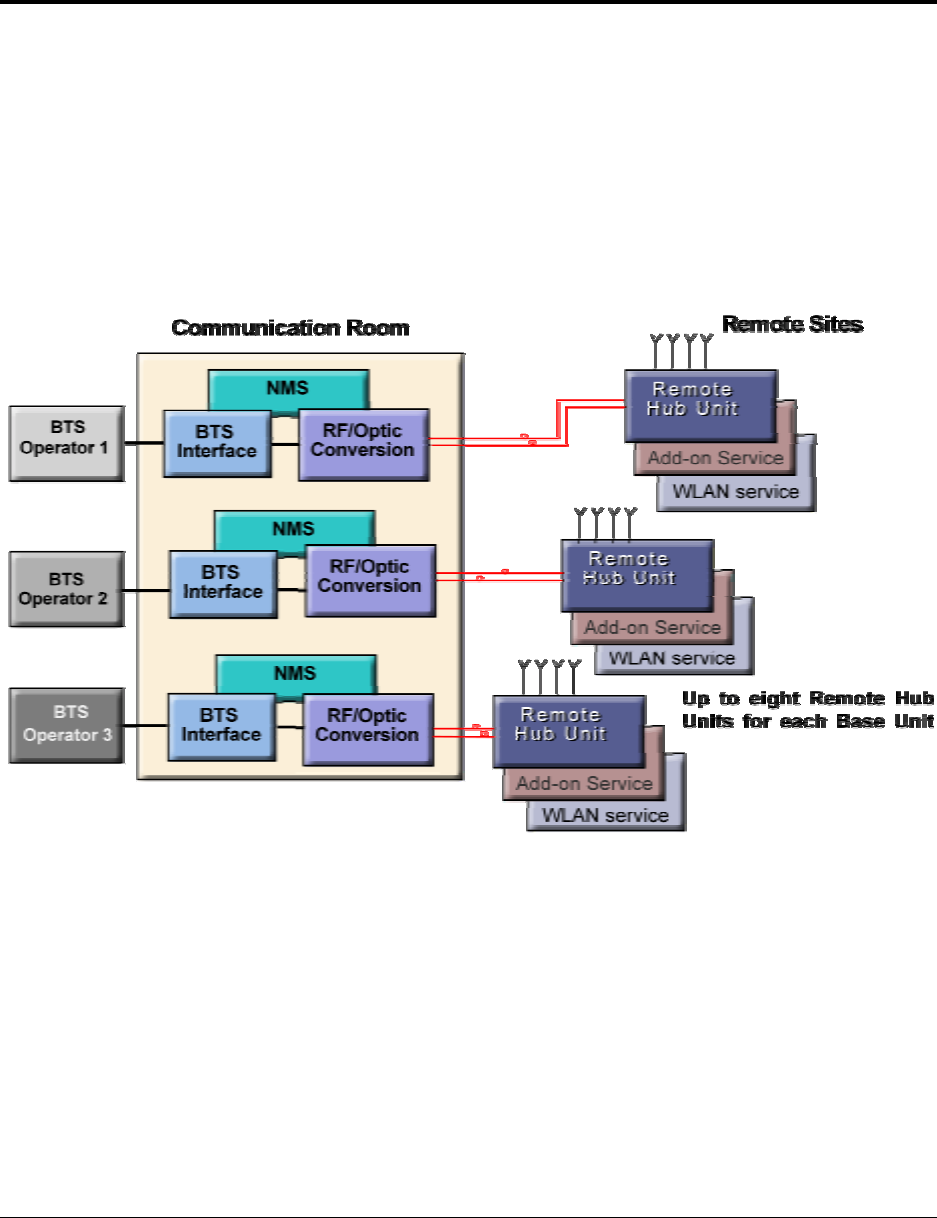
Figure 1-1. MA 1000 System Overview
Voice services are transmitted between the BTS side and the locations via optic fiber after
the appropriate conversion from RF to optic, and reconverted to RF at each end. The MA
1000 system provides entry level solutions that can be upgraded
using the same
infrastructure
to support additional services as required.
Wireless 802.11/a/b/g coverage may be integrated into the MA 1000 system using the MA
850 remote module (that supports wireless LAN service distribution).

MA 1000 Installation and Configuration Guide
2
To optimize system coverage under changing environmental conditions or load, as well as to
enable remote monitoring of all system elements from a central location, MobileAccess
provides the following MA 1000 system enhancement solutions:
• Manageable BTS interface devices that control the level of the BTS signal fed into
the system (Radio Interface Unit)
• Network Management System (NMS) consisting of controllers, adjustment and
management software
1.1.1 Features
• Support for all current and future technologies such as TDMA, CDMA, WCDMA and
GSM, and services such as PCS/CELLULAR, Paging, iDEN and 802.11 (a/b/g)
Wireless LAN
• All services are distributed through a
single
coax and antenna infrastructure
• All active components are located in the communication closet/room
• Modular, scalable and future-safe – additional remote units can
easily
be installed
• Support for remote monitoring through MA 410/430 controllers
• Eliminates RF interferences occurring where multiple antenna systems are used to
serve multiple services
• Enables fast deployment for corporate enterprises, property owners and WSP’s of
new services
• Reduces tenant disruption
• Low power required by the system eliminates the need for high power BTS/RBS,
reducing operator expenses
• Provides both local and remote monitoring and control capabilities
• Software programmable parameters including output power, AGC (on/off and
levels), and system gain
• Real time component setting capabilities for optimal performance (aging,
temperature, optical connectors, etc.,)
MA 1000 Installation and Configuration Guide
3
1.2 System Architecture
The MA 1000 solution is based on the following main elements:
• MA Base Units (BUs) – The BUs perform RF to optic conversion on the BTS side.
• MA Remote Hub Units (RHUs) 1000 – The MA 1000 performs the RF to optic
signal conversion at the antenna side for up to two services corresponding to the
RHU model. A third service can be added by connecting an add-on remote hub unit
(MA 1200) to the RHU 1000.
• MA 850 – The MA 850 is a wireless LAN module that provides secure and
centralized connections for 802.11a/b/g Access Points and distributes the wireless
services over the same coax and broadband infrastructure as the voice services.
All services are combined and distributed through the same antenna broadband
infrastructure.
To provide optimum coverage at all times and monitoring and control of all system elements
from a central location MA provides the following devices:
• MA Radio Interface Units (RIUs) – The RIUs provide interfaces for up to three
BTS/BDA signals, and automatically adjusts the output signal in respose to input
signal level in order to provide optimal coverage.
• MA 410/430 controllers – The controllers enable remote monitoring of the
system elements from a
single location
via advanced intuitive GUI.
1.3 Configuration Options
The MobileAccess™ 1000/1200 system includes three basic configuration options:
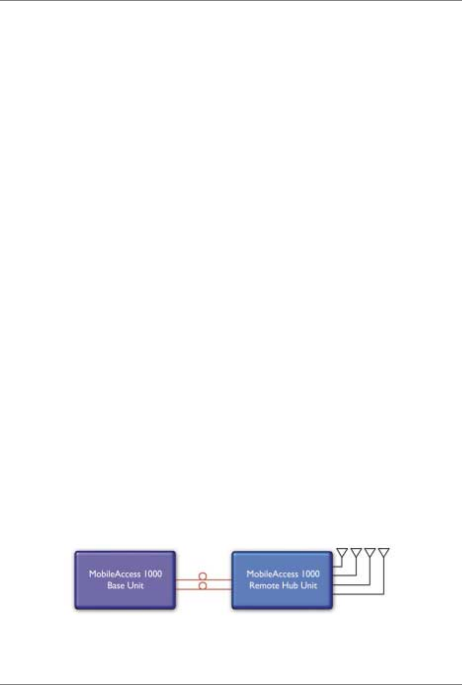
A) Basic configuration
The Base Unit drives a single or dual band, MobileAccess™ 1000 RHU. The dual band
RHU consists of a low band service (cellular 800, iDEN, Paging, or GSM 900) and a high
band service (PCS 1900 or DCS 1800).
Figure 1-2. MobileAccess 1000 Basic BU – RHU Configuration
MA 1000 Installation and Configuration Guide
4
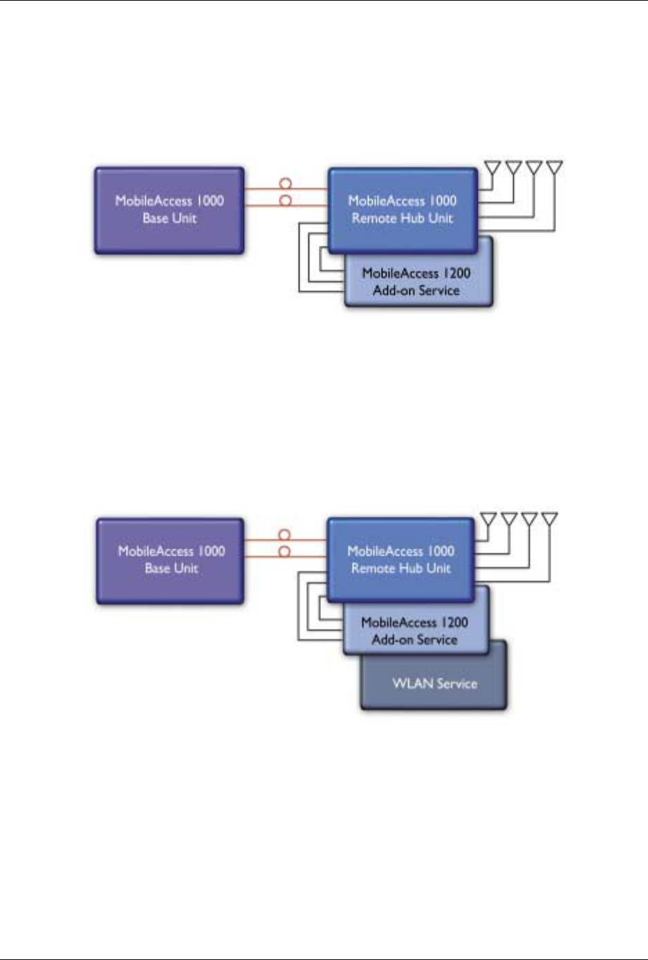
B) Using the MobileAccess 1200 add-on unit to provide an additional service
A MobileAccess™ 1200 add-on unit can be connected to a MA RHU 2000 unit to provide
a third service. The add-on unit can be Cellular, PCS, UMTS, 3G, or any future service.
Figure 1-3. MobileAccess 1000/1200 BU – RHU Plus Add-On
C) Using the MobileAccess 800 WLAN module to provide access to high data-
rate service
A WLAN module (MobileAccess™ 800) may also be added in a configuration that
includes both RHU 1000 and RHU 1200 or only RHU 1000.
Figure 1-4. MobileAccess 1000/1200 BU – RHU Plus Add-on Plus WLAN Configuration

MA 1000 Installation and Configuration Guide
5
1.4 MA 410/430 Remote Management
The MobileAccess (MA) Network Management System (NMS) provides complete site
coverage and network management. It can be used to provision coverage that can
compensate for changing loads. It also provides real-time monitoring, control and
diagnostics capabilities for
MobileAccess
devices from a single location.
NOTE: The MA NMS System is fully described in the MA NMS System Configuration and
Operation Guide.
The MA NMS system consists of:
• MA 410/430 Controller – The controller provides the interface between the
system elements and the management and control mechanism. Two controller
models are available:
• MobileAccess 410™ – enables management of the connected devices through a
local or point-to-point dial-up connection. It can be remotely managed through a
connection to the MobileAccess 430 controller.
• MobileAccess 430™ – enables management of all connected elements and all
connected MA 410 controllers and the corresponding elements. Supports SNMP
(Simple Network Management Protocol) over TCP/IP connection.
• MA 430 may be managed through the Network Operator Center (NOC) through
Manager of Mangers element such as HP OpenView via SNMP.
• MCT – a Java based GUI application provided with both controllers. The MCT is
used after the installation procedure to adjust MobileAccess devices according to
the installation site characteristics in order to optimize coverage for the site.
The application is installed and ran from a computer that is connected either locally or
via remote dial-up modem to the controller site to be adjusted or monitored.
• MobileAccess Manager™ – a Java based GUI software application that provides
enhanced monitoring and control capabilities for all your
MA 430™
sites from a
single location; each site can consist of a standalone MA 430 controller, or a MA 430
controller in a Master topology with a number of MA 410 controllers connected as
slaves. The MobileAccess Manager application is not supplied with the controller
– it is
purchased separately.
The MA NMS application is installed on a server and is accessed from any client by
connecting to the server from any Web Browser with enhanced Java VM capabilities.
MA 1000 Installation and Configuration Guide
6
MA NMS manager provides the following features and capabilities:
• Remote SNMP management from a single location
• Client/server management capability over a TCP/IP network with enhanced
monitoring and control capabilities
• Intuitive GUI that enables end-to-end fault sourcing from RIU to antennas. The GUI
includes:
• System status at a glance through multi-color tree with upward propagation of fault
indications
• Graphical view of system elements including LED status displays and auxiliary
connections
• Multi-color event monitoring display
•
RF Connections
1.5 MobileAccess Models
Table
1-1: MobileAccess™ BU Models
MobileAccess Universal Base Units (1000, 1200, 2000 support)
WB-B8U Wide Band Base 8 Unit supporting 8 RHUs
WB-B4U Wide Band Base 4 Unit supporting 4 RHUs
Table
1-2: MobileAccess™ RHU Models with Add-on Capabilities
MobileAccess 1000 RHUs (ready for add-on units)
1000S-CELL-4 Single band-Cellular, 4 ports
1000S-IDEN-4 Single band-iDEN, 4 ports
1000S-PCS-4 Single band-PCS 4 ports
1000D-IDEN-PCS4 Dual band-iDEN/PCS, 4 ports
1000D-SMR-PCS4 Dual band-SMR/PAGING/PCS, 4 ports
1000D-CELL-PCS4 Dual band-Cell/PCS, 4 ports
1000D-CELL-DCS4 Dual band Cell/DCS 4P ready for add-on units
1000D-CL-M-DCS4 Dual band Cell multi operator/DCS 4P ready for add-on units
1000D-GSM-DCS4 Dual band GSM/DCS 4P ready for add-on units
1000D-GSMO-DCS4 Dual band GSM orange/DCS 4P ready for add-on units
MA 1000 Installation and Configuration Guide
7
Table
1-3: MobileAccess™ RHU Models
MobileAccess 1000 RHUs (Litenna compatible)
10L-D-IDEN-PCS4 Dual band-iDEN/PCS, 4 ports, LBC
10L-D-SMR-PCS4 Dual band-SMR/PAGING/PCS, 4 ports, LBC
10L-D-CELL-PCS4 Dual band-Cell/PCS, 4 ports, LBC
10L-D-CELL-DCS4 DB Cell/DCS 4P ready for add-on units-LBC
10L-D-CL-M-DCS4 DB Cell multi opr/DCS 4P ready for add-on units-LBC
10L-D-GSM-DCS4 DB GSM/DCS 4P ready for add-on units-LBC
10L-D-GSMO-DCS4 DB GSM orange/DCS 4P ready for add-on units-LBC
Table
1-4: MobileAccess™ 1200 RHU Models
MobileAccess 1200 RHU
1200-PCS-SA-1 Stand Alone high power PCS, one port
1200-UMTS-SA-1 Stand Alone high power UMTS, one port RHU
1200-PCS-AO Add-on RHU supporting a PCS service
1200-UMTS-AO Add-on RHU supporting UMTS service
Table
1-5: MobileAccess™ UMTS Ready RHU Models
MobileAccess 1200 RHU (Litenna UMTS Ready compatible)
12L-UMTS-AO Add-on RHU supporting UMTS service LBC
Table
1-6: MobileAccess™ Controller Models
Network Controller
410 Network Controller – Serial Interface (dial-up)
430 Network Controller –Ethernet/IP Interface
Table
1-7: MobileAccess™ Management System
Network Management System
NMS-SW-SERVER GUI and server S/W package (one per site)
NMS-SW-MFEE NMS annual S/W maintenance fee (per 430-CTLR)

MA 1000 Installation and Configuration Guide
8
Table
1-8: MobileAccess™ RIU
Radio Interface Unit
RIU-IM Radio Interface Unit
RIU-BTSC-CELL BTS Conditioner for Cellular
RIU-BTSC-IDEN BTS Conditioner for iDEN
RIU-BTSC-PCS BTS Conditioner for PCS
RIU-BTSC-SMR BTS Conditioner for SMR-Paging
RIU-BTSC-GSM BTS Conditioner for GSM 900MHz
RIU-BTSC-GSM-O BTS Conditioner for GSM 900MHz for Orange
RIU-BTSC-DCS BTS Conditioner for DCS 1800MHz
RIU-BTSC-UMTS BTS Conditioner for UMTS 2100MHz

MA 1000 Installation and Configuration Guide
9
2
2
S
Sy
ys
st
te
em
m
E
El
le
em
me
en
nt
ts
s
This chapter describes each of the system elements, and their individual connections. It can
be used as reference to verify the connections of each module or to upgrade your system.
2.1 Remote Modules
The Optical to RF conversion of each service at the individual building floors is performed by
remote units corresponding to the service types. These consist of MA 1000 RHUs and in
addition, may include MA 1200 add on modules and MA 850 modules.
The configurations depend on the requirements of the site and the supported services. The
following sections describe each of the system elements.
NOTE: The connections as they relate to the MA 1000 system are described in Chapter
4 -
System Installation.
2.1.1 MA 1000 RHUs
Each RHU supports two different services (one high-band and one low-band). All RHUs are
add-on ready, meaning that their optic interface and control functionality can support a
third (high-power) service through the connections of a MA 1200 Add-on module (see
section
0).
Each RHU 1000 is connected to the corresponding BU (located in the communication room)
through a fiber optic connection. Remote monitoring is provided through the BU
connections to the MA 410/430 controller (see section
2.4).
The RHU 1000 services, MA 1200 add-on service and data services (provided by MA 850 -
2.1.3) at each location are combined and then transmitted over a common infrastructure to
strategically placed antennas.
MA 1000 Installation and Configuration Guide
10
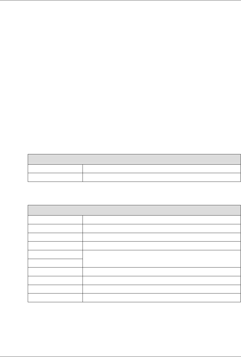
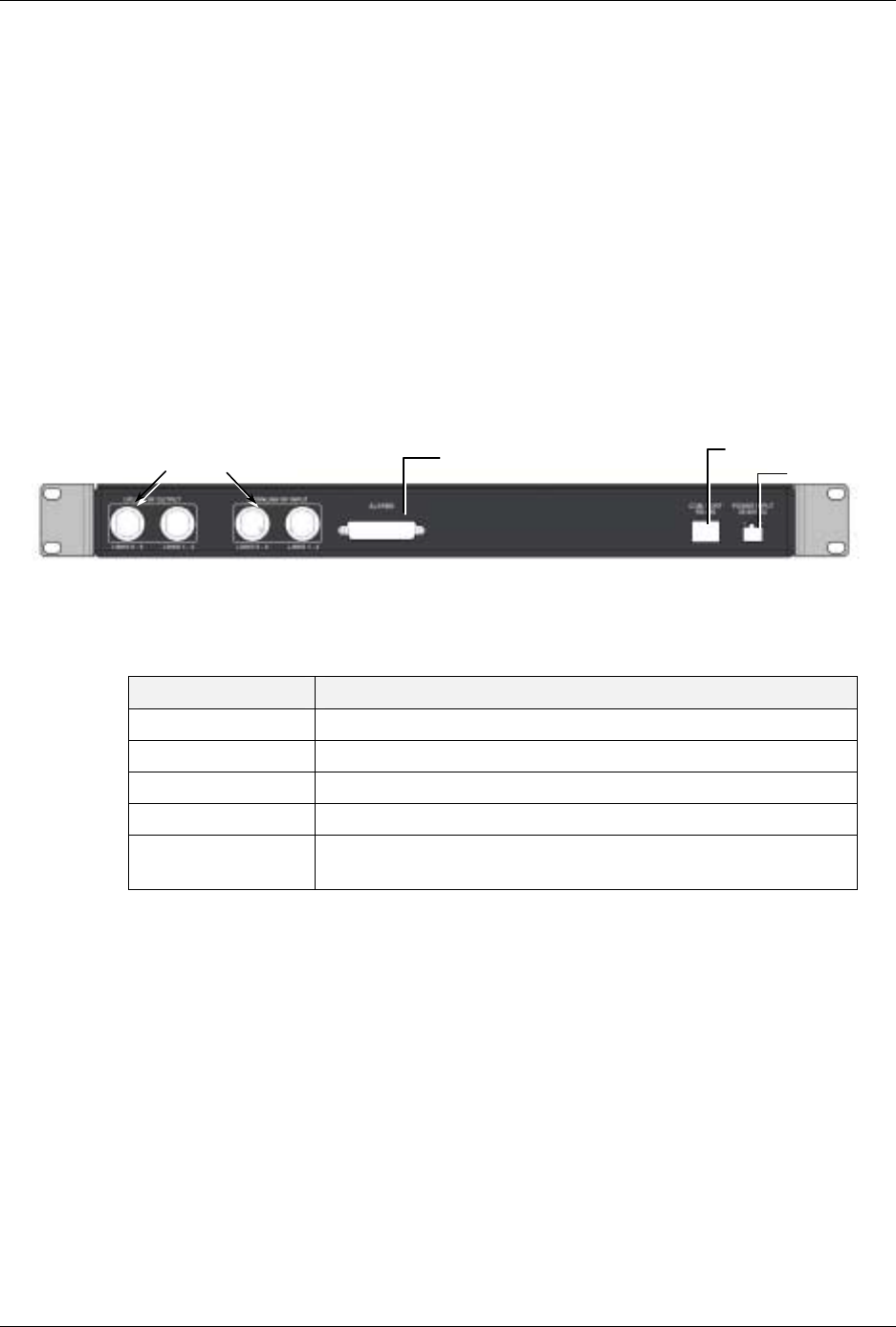
2.1.1.1 RHU 1000 Front Panel
The RHU 1000 front panel contains the fiber optic connections to the BU, four coax
connections to the antennas, power connections and status indicators.
If RHU 1000 and MA 1200 add-on units are installed, then the combined services are fed to
the coax infrastructure through the
RHU 1000 antenna ports
. However, if MA 850 is also
installed, the combined
data and voice
services are fed to the coax infrastructure through
the
MA 850 antenna ports
.
NOTE: To provide alarms, the antenna must supply a DC resistance of up to 5K ohms.
Figure 2-1. RHU 1000 Front Panel
Table 2-1. RHU 1000 Front Panel Indicators
LED Description
COMM Active communication detected
LINK Optical link to BU detected
PWR DC power connected
F/O BU connections Power connector
LEDs
MA service connector
RF
p
orts 1 to 4
MA 1000 Installation and Configuration Guide
11
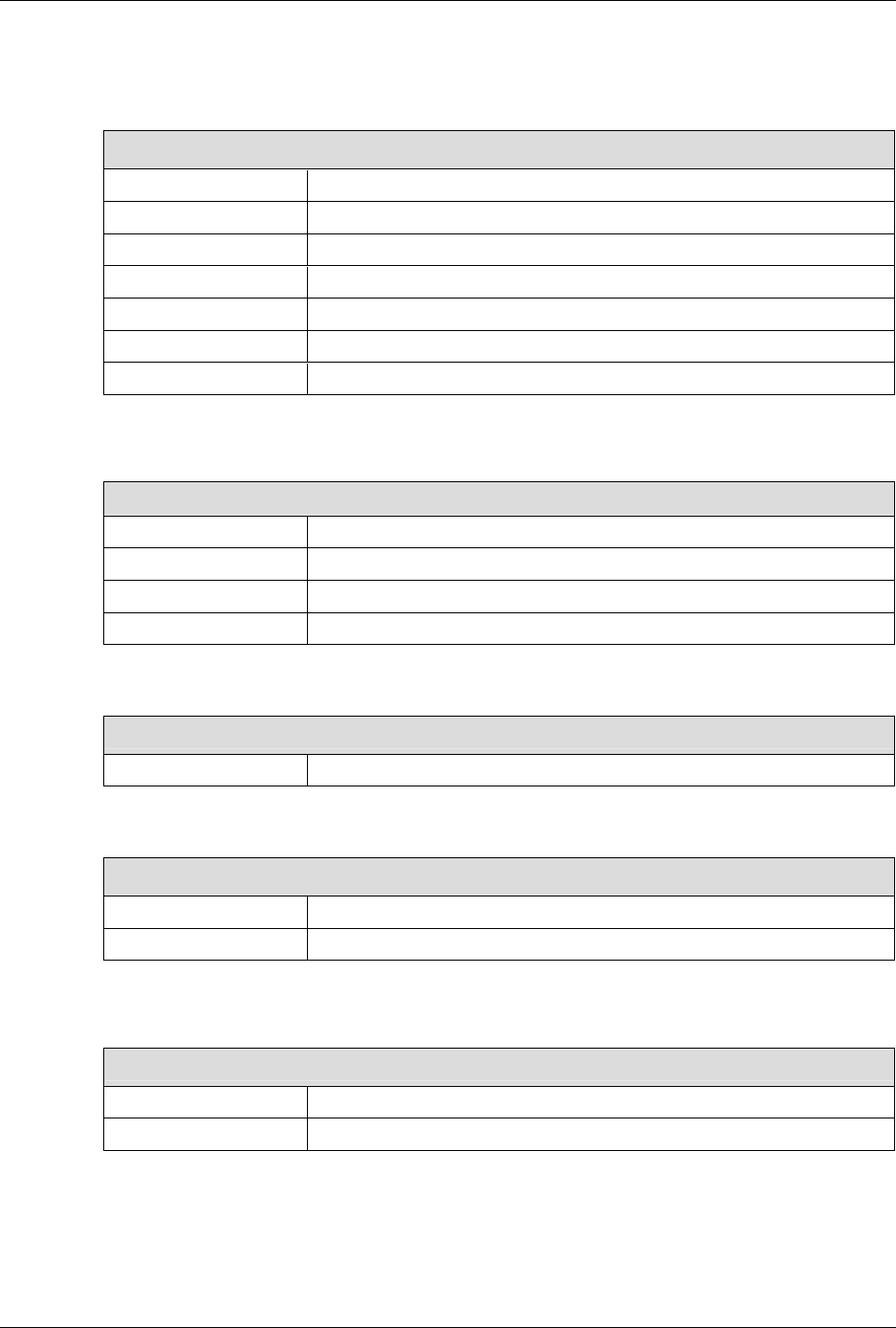
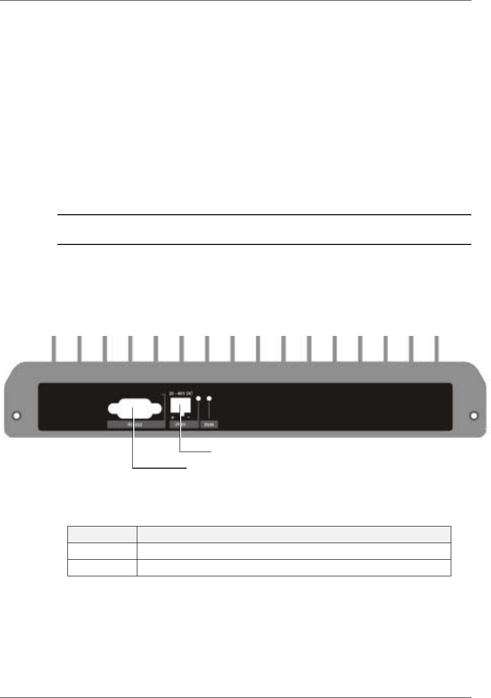
2.1.1.2 RHU 1000 Rear Panel
The RHU 1000 rear-panel provides the control, RF interface and optic interface ports that
enable connecting an MA 1200 add-on unit to the RHU 1000 module.
Figure 2-2. RHU 1000 Rear
Table 2-2. RHU 1000 Rear Panel Connectors
Add-on control Transmits the control signals from MA 1200 add-on module to the
RHU 1000 module. Connected to the MA 1200 add-on Control
From port.
High Band Connects to the 1200 Add-on High Band port. Provides the
interface to the Add-on RF service which is combined with the RHU
services and distributed through the common coax infrastructure.
DL, UL Transmit the RF signals to- and from- the MA 1200 add-on module.
These ports are connected to the corresponding ports on the MA
1200 rear panel: DL to DL, UL to UL.
MA 1000 Installation and Configuration Guide
12
2.1.2 MA 1200 Add-on
The MobileAccess 1200 Add-on module is a high power module, supporting a single
frequency band (low or high). It is designed to be integrated with a host
RHU 1000
module.
The RHU 1000 module provides the following functionality for both units:
• Optical interface (to the BU) and conversion
• RF interface (to antennas) and conversion
• Control signals
In addition, MA 850 services can also be combined with MA 1200 add-on and RHU 1000
services. (However, in this type of configuration the combined services interface to the coax
infrastructure through the MA 850 ports.)
NOTE: The units are integrated through simple external cable connections between
corresponding ports.
2.1.2.1 MA 1200 Front Panel
The RHU 1200 front panel contains the power connection and status LEDs. (The RS-232
connector is reserved for MA service personnel).
Figure 2-3. RHU 1200 Front panels
Table 2-3. MobileAccess 1200 Front Panel Indicators
LED Description
RUN When blinking, indicates that the RHU is in normal operating mode.
PWR Power ON
MA service connector
Power connector
MA 1000 Installation and Configuration Guide
13
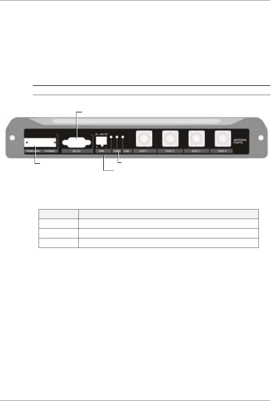
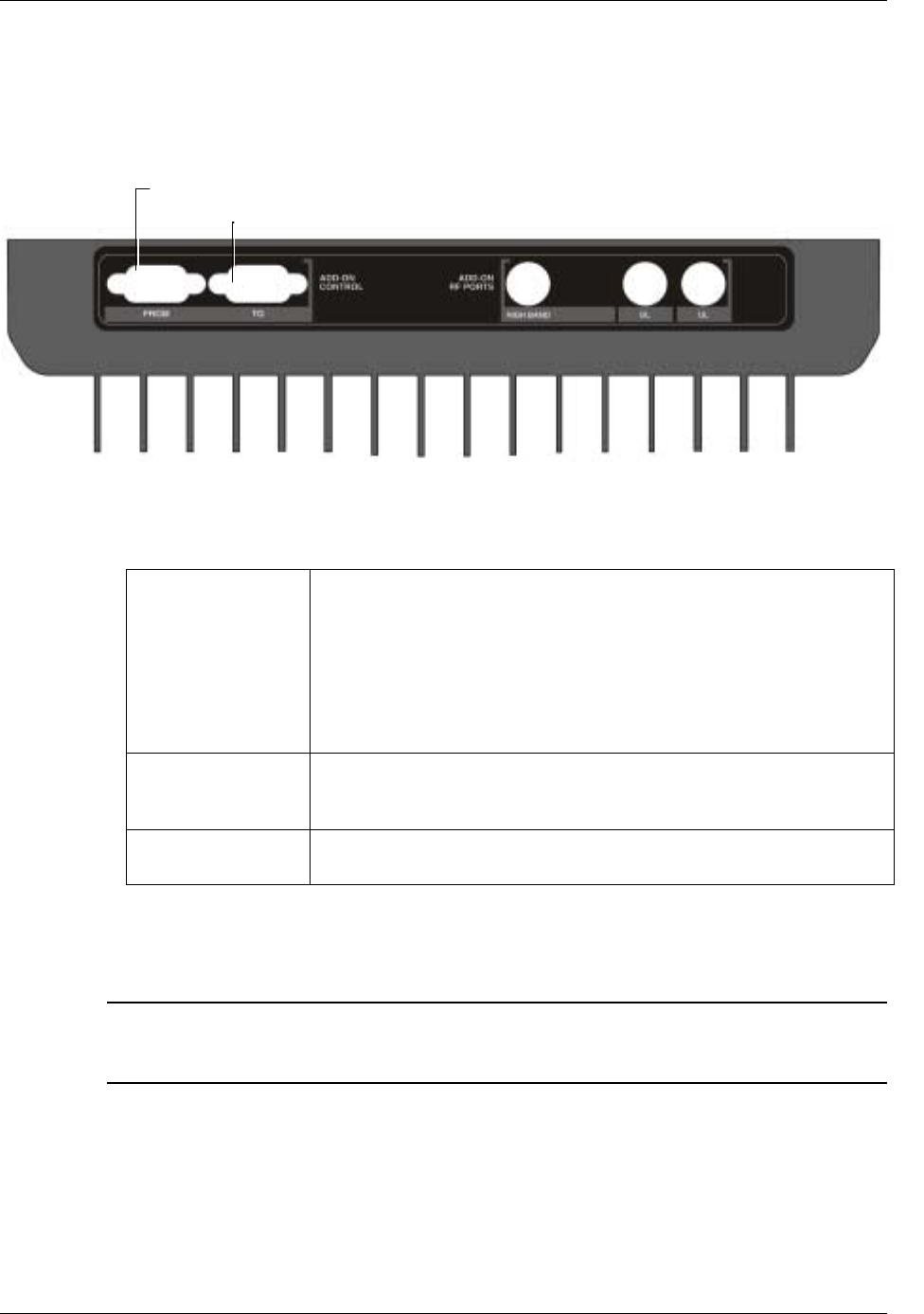
2.1.2.2 MA 1200 Rear Panel
The RHU 1200 rear panel contains the connections to the RHU 1000 and MA 850.
Figure 2-4. RHU 1200 Rear Panel
Table 2-4. RHU 1200 Rear Panel Connectors
Add-on Control Transmits the control signals between the MA 1200 module and
the MA 850 and RHU 1000 modules.
From – receives control signals from the RHU 1000. Connected to
the RHU 1000 Add-on Control connector.
To – for configurations that include MA 850. Transmits control
signals to MA 850. Connected to the MA 850 Add-on Control
connector.
DL, UL Transmit the RF signals to- and from- the MA 1200 add-on module.
These ports are connected to the corresponding ports on the MA
1000 rear panel: DL to DL, UL to UL.
High RF service output port connected to the RHU 1000 rear-panel
High port.
2.1.3 MA-850 Module
NOTE: This section provides a brief overview of the MA 850 module. For detailed
information on installation and connections, refer to the MA 850 Installation and
Configuration Guide.
MobileAccess 850
provides a
secure
and
centralized
connection for 802.11a/b/g Access
Points. It significantly expands 802.11 coverage and enables distributing data and voice
services over the same coax and antenna infrastructure used by MA 1000 system.
MA 850 may be assembled on top of the RHU 1000 or MA 1200 add-on. It is integrated into
the MA 1000 system by interconnecting the appropriate connectors. The combined signals
RHU 1000 Add-on control
MA 850 Add-on control To RHU 1000 High, DL and
UL connectors.
MA 1000 Installation and Configuration Guide
14
of the MA 1000 system input to the MA 850 module and then distributed through the same
coax broadband antenna infrastructure
connected to the MA 850.
MA 850 may be remotely monitored through the RHU 1000 system to which it is integrated,
and remotely configured through a point-to-point Ethernet connection.
The MA 850 front and rear panels, connectors and connections are described in detail in the
following sections.
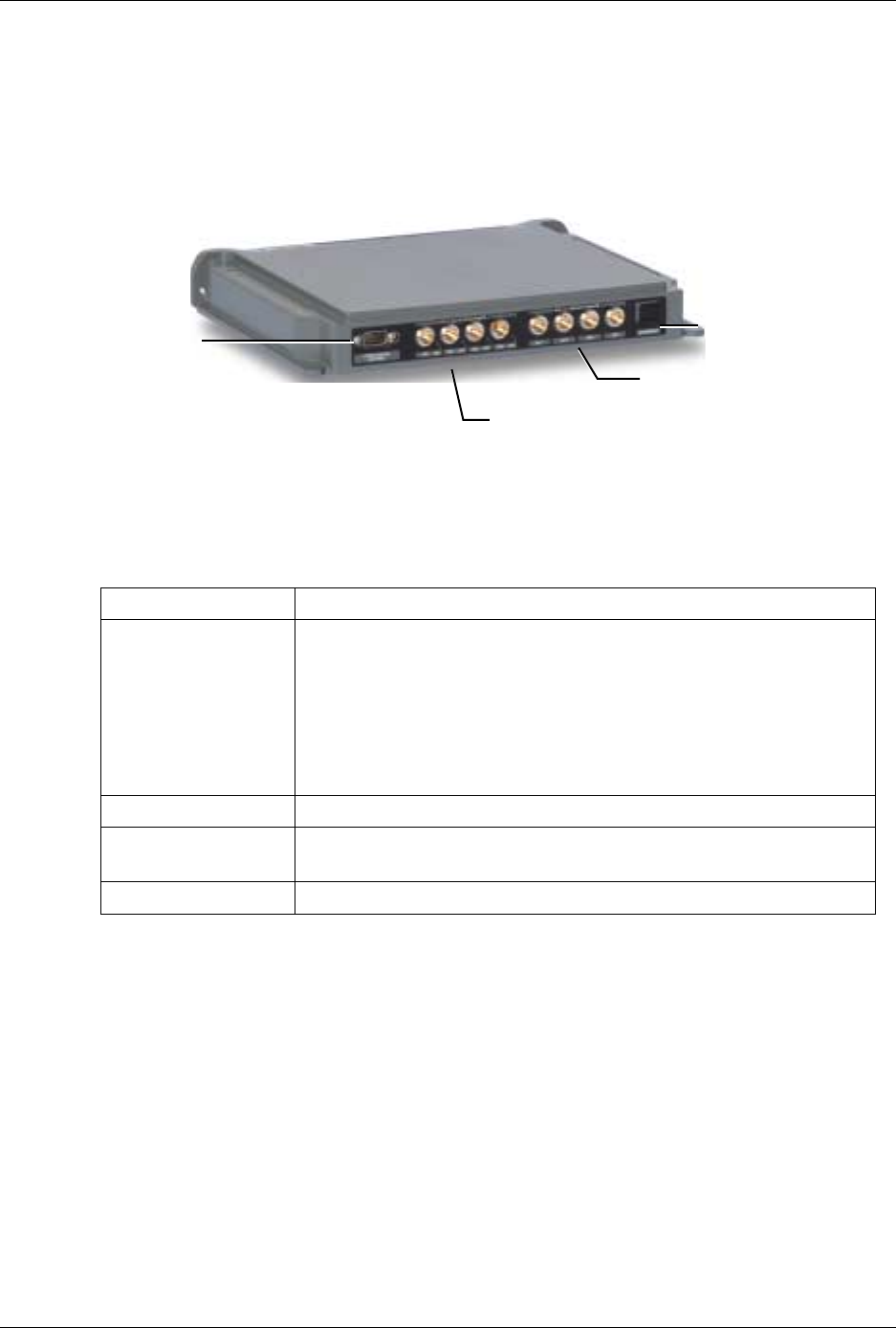
2.1.3.1 MA 850 Front Panel
The MA 850 front panel contains the antenna ports interfaces, local configuration interface
and power connection.
NOTE: Whether connected alone or integrated with RHU 1000 modules, the coax
infrastructure is connected to the MA 850 coax ports.
The following figure shows the MA 850 front panel.
Figure 2-5. MobileAccess 850 Front View
Table 2-5. MA 850 Front Panel Connections
Front Panel Description
Mobile Services Four SMA female connections to which the antenna port of the
MA 1000 system are connected.
To be terminated with 50 ohm terminations when not in
use.
Antenna Ports Four n-type female antenna connections
Local Local connection for setup
DC Power connection: 20V to 48V from a standard power supply
A
ntenna
p
orts
Connections to
corresponding antenna
ports of remote unit
Local RS232 connection
for configuration
Power
MA 1000 Installation and Configuration Guide
15
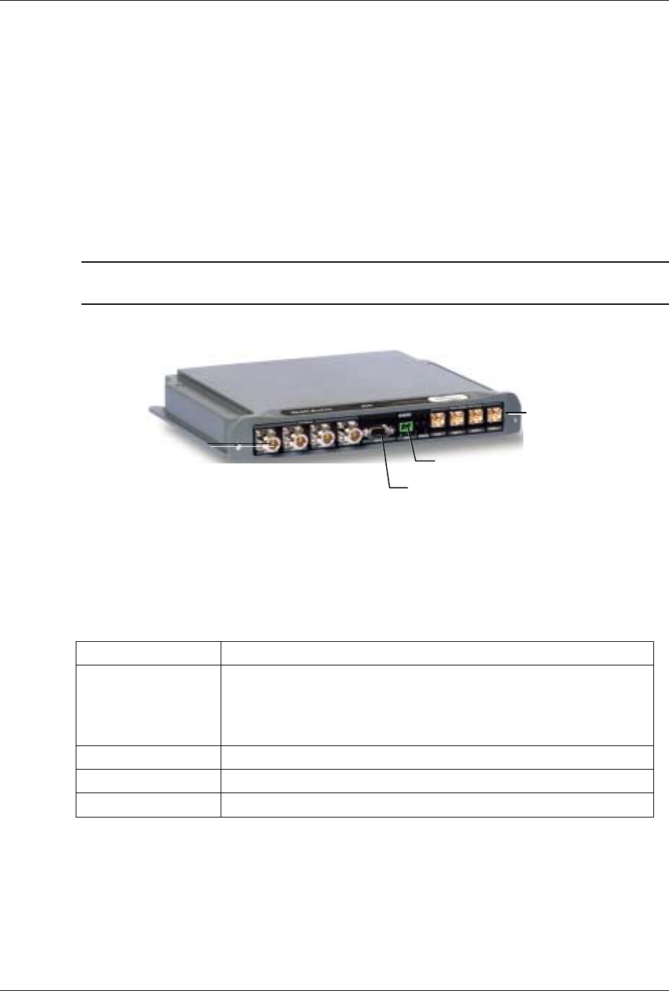
2.1.3.2 MA 850 Rear Panel
The MA 850 rear panel contains the connections to the APs, the Ethernet port for remote
configuration and the connection to the MA 1200 add-on control (if an MA 1200 add-on unit
is installed)
Figure 2-6. MobileAccess 850 Rear View
Table 2-6. MA 850 Reart Panel Connections
Rear Panel Description
802.11b,g APs Connection to up to four 802.11b/g APs, where associated LED
Lite under the following conditions:
•
Green: indicates where AP should be connected after
configuration
•
Green flickering: Link with AP established but no data is
received
•
Red: AP transmitting data
802.11a APs Connection to up to four 802.11a APs
Connection to
control Connection to MA 1200 To connector on the rear panel. Used for
viewing antenna status
Ethernet port Connection to network for Web configuration
802.11 b/g APs
connections
Ethernet
Port
802.11 a APs
connections
Connection to
add-on control
MA 1000 Installation and Configuration Guide
16
2.2 Radio Interface Unit (RIU)
The RIU is an operator dedicated unit that interfaces to up to three BTS sources and
automatically adjusts the signal output according to changing environmental conditions in
order to provide optimal coverage for the site. The RIU is remotely monitored and
managed.
Each RIU can support up to three BTS Conditioner (BTSC) sub-modules, where each sub-
module provides interface to a BTS or BDA of
the same type of service
.
Each RIU can be connected to
four
8-port Base Units (real panel connections) or to
eight
4-
port Base Units.
Additional BUs can be supported by using splitters and combiners connected to the front
panel Expansion connectors.
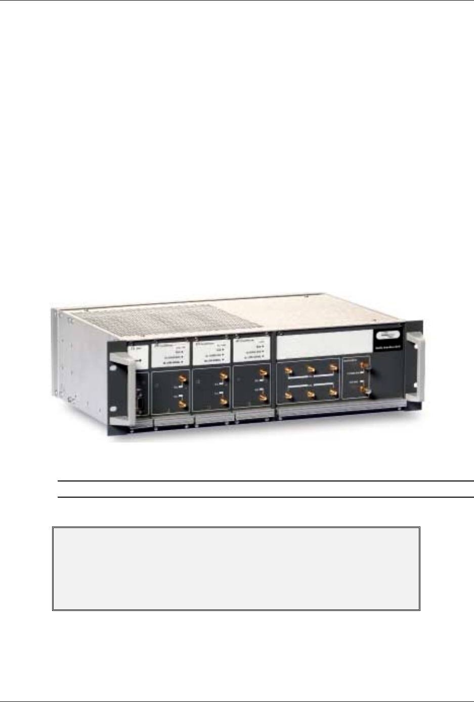
The following figures shows an RIU with three BTSC sub-modules.
Figure 2-7. RIU
Note: All connections are via RG223 coax cables with 1/2" N-type male connectors
ATTENTION
The RIU is factory set to 0dB gain on the uplink and downlink. In order to
operate properly, an ADJUSTMENT process is required in the field.
Any unused input and output connectors MUST be terminated with 50 ohms –
otherwise the ADJUSMENT procedure results may be affected.
MA 1000 Installation and Configuration Guide
17
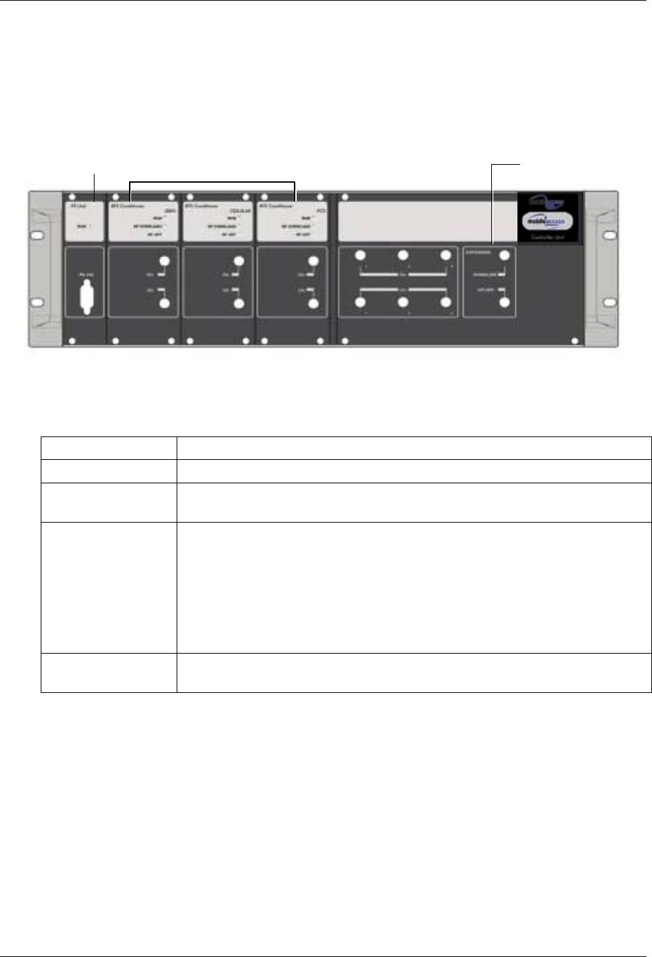
2.2.1.1 RIU Front Panel
The RIU front panel contains the indicators and expansion connectors for the connection of
additional BUs.
Figure 2-8. RIU Front Panel
Table 2-7. RIU Front Panel Indicators
LED Description
P.S UNIT PWR ON – input signal is at the required level.
BTS CONDITIONER
RUN Flashing -- CPU is running and software loaded
BTS CONDITIONER DL
OVERLOAD Continuous Red – RF switch is disconnected to protect the system. This
may be due to:
•
Unpredicted power rise for which the attenuation response was
insufficient to compensate and reduce the power to the required level.
•
Software problem detected.
Flashing: When the BTSC DL output power is more than 3dB of the
calibrated value.
BTS CONDITIONER DL
LOW Continuous Red – if the BTSC DL power is at least 15dB lower than the
calibrated BTSC max power level. This condition also triggers an event.
Power Su
pp
l
y
BTS Conditioners Expansion connectors - for
connectin
g
additional BUs
MA 1000 Installation and Configuration Guide
18
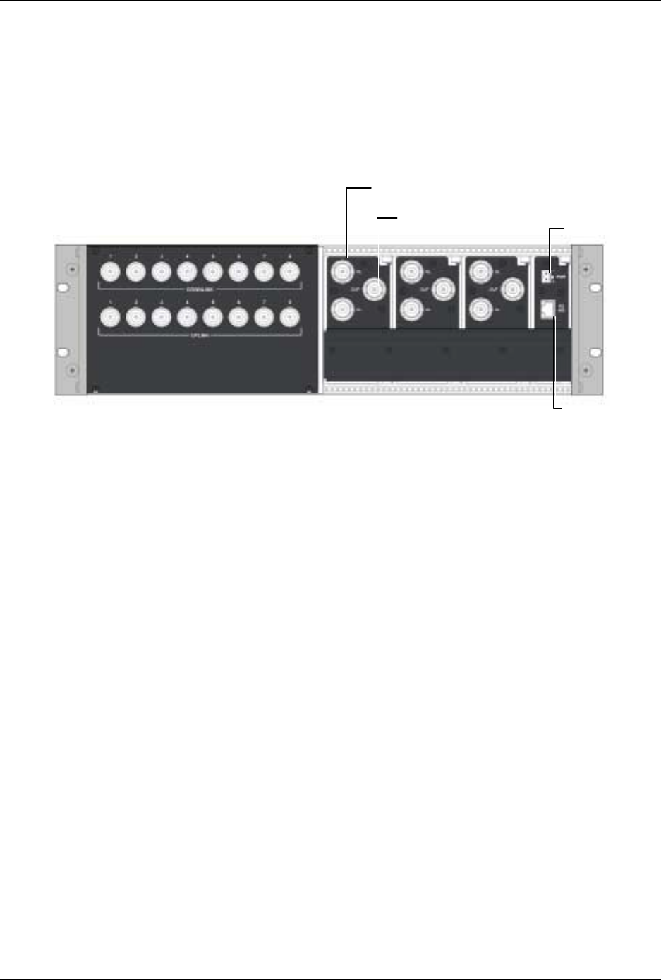
2.2.1.2 RIU Rear Panel
The rear-panel provides all the connections on the BTS side and on the BU side as well as
connections to the MobileAccess 410/430 controller and the power connection. Two types of
BTS side connections are available for each BTS conditioner: simplex and duplex.
Figure 2-9. RIU Rear Panel showing the RF Connection
2.3 MA Base Units
The BUs (Base Units) perform RF to optical conversion of the signal on the BTS/BDA side.
Each can support up to two services (provided by the same operator). Two models of MA
BUs are available: four-port unit – supporting four RHUs, and eight-port unit supporting up
to eight RHUs. The RHU models correspond to the services supplied through the BUs.
The BU (and all the corresponding remote units) may be remotely monitored and managed
via the MA NMS (Network Management System).
The BUs are usually installed in the telecom room adjacent to the BTS/BDA signal source.
RF ports on the rear panel provide interface to the BTS side (through connection to RIU or
passive interface), while optic ports on the front panel provide interface to the RHUs
(Remote Units). This following sections describe the MA BU front and rear panels, including
indicators and connectors.
BU connections; one UL and one DL
connection for ever
y
g
rou
p
of four
ports (single OPTM) on the BU. Power
MA Controller
connection
BTS/BDA sim
p
lex connections
BTS/BDA du
p
lex connections
MA 1000 Installation and Configuration Guide
19
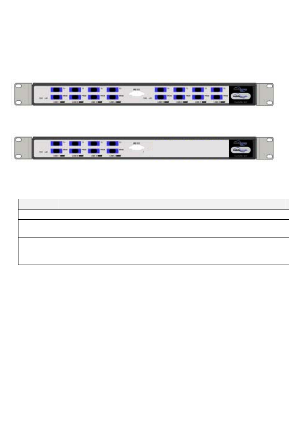
2.3.1.1 MA BU Front Panel
The front panel contains the optical connections and indicators. The BU is available in two
configurations: Four-port - and Eight-port BUs. The eight-port BU consists of two four-
port elements where each four-port element has a dedicated set of indicators (PWR, LSR
and Link 1 to Link 4 or Link 5 to Link 8).
Figure 2-10. Eight-Port MA BU Front Panel
Figure 2-11. Four-Port BU Front Panel
Table 2-8. MA BU Front Panel Indicators
LED Description
PWR Power input detected for the corresponding unit.
LSR ON - laser circuitry for the corresponding element (group of four ports) is
functioning correctly.
Link 1-4, 5-8 ON - the optical link to/from the connected remote functions within the
specifications in both directions.
Blinking - optical power from remote is lower than expected by at least 2 dBm
Four
p
orts and corres
p
ondin
g
indicators Four
p
orts and corres
p
ondin
g
indicators
MA 1000 Installation and Configuration Guide
20
2.3.1.2 BU Rear Panel
The BU rear panel contains the RF, Alarms, NMS and power connections. Note that there
are two uplink and two downlink RF connections to the BTS side (to an Interface Box or
RIU) - each individual uplink and downlink connection corresponds to a four-port BU
element. For a four-port BU, one uplink and one downlink port is connected; for an eight-
port BU, two uplink and two downlink ports are connected.
For systems that include MA 430 controllers, the RS 485 port is connected to the MA
410/430 controller to enable remote monitoring and management of the BU from a central
location. For systems without remote management, the Alarms dry-contact connector pins
can be connected to the BTS to provide alarms functionality.
Figure 2-12. MA BU Rear Panel (RF Connections)
Table 2-9. MobileAccess 1000 Rear Panel Connections
Connector Description
Uplink output Uplink connectors to be connected on BTS side.
Downlink input Downlink connectors to be connected on the BTS side.
Com Port RS485 Connection to MobileAccess 410/430 controller.
PWR Power connection
Alarms Dry-contact connections to BTS/BDA (normally closed).
Relevant only for system without MA 410/430 controllers.
Pair of uplink and downlink RF
connections for interface to BTS Alarms dry-
contact
t
MA 410/430
Power
MA 1000 Installation and Configuration Guide
21
2.4 MobileAccess NMS System
NOTE: This section provides general information on the MobileAccess 410/430 Controller.
For detailed information on the controller, configuration and connections refer to the Mobile
Access NMS User
’
s Guide.
The MobileAccess controllers enable managing and controlling the MobileAccess system
elements. All the monitoring and control operations can be performed from the Master’s
location.
Two MobileAccess controller configurations are provided: MobileAccess 410 and
MobileAccess 430. The models differ in their remote access capabilities:
• MobileAccess 410 provides point-to-point connectivity implemented via either direct
RS232 connection or via connection to a DSPN phone line
• MobileAccess 430 provides client/server management capability over TCP/IP
network with enhanced monitoring and control capabilities (in addition to the
connectivity options provided by MobileAccess 410).
NOTE: The MobileAccess 430 front panel is differentiated from the MobileAccess 410 front
panel by the SNMP Agent Card that provides TCP/IP management capabilities.
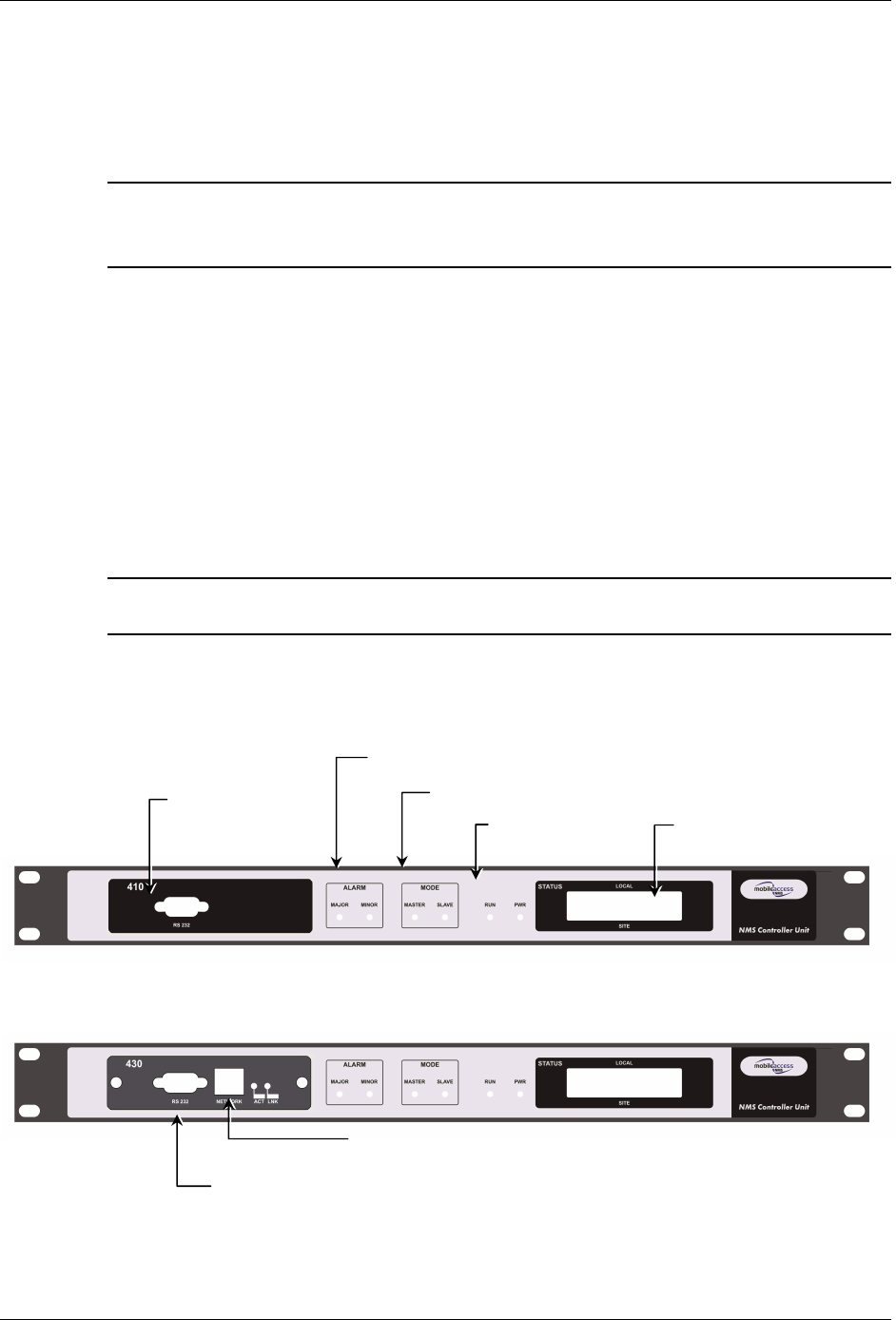
Controller Front Panel
Figure 2-13. MobileAccess 410 Front Panel
Figure 2-14. MobileAccess 430 Front Panel
Local RS232
connection (for IP
address setu
p)
LCD alarm display
corresponding to Major
and Minor LEDs
Major, Minor LED
indicators
Master/Slave confi
g
uration
Run and
Power LEDs
TCP/IP connection
Local RS232 connection to Laptop
(MA 300 for Remote controller)
MA 1000 Installation and Configuration Guide
22
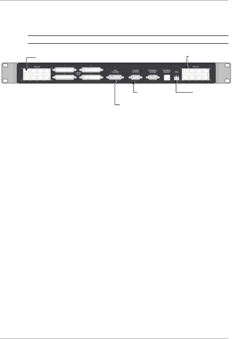
Controller Rear Panel
Note: The rear panels for the MobileAccess 410 and MobileAccess 430 are the same.
Figure 2-15. MobileAccess 410/430 Rear Panel
DC In
p
ut
General purpose
alarms input (MA 300).
BTS alarms output
MA BU and RIU
inputs
Slave controller
connections

23
3
3
S
Si
it
te
e
P
Pr
re
ep
pa
ar
ra
at
ti
io
on
n
3.1 Infrastructure Preparation
This following installation rules are based on the assumption that site survey and installation
planning (
including power requirements
) have been completed.
3.2 Installation Requirements
The infrastructure preparation consists of two main phases:
A. Floor Planning: Planning the distribution of the antennas on each floor to provide the
required coverage.
B. Telecom Closet Planning: Planning the layout of the devices and cables in the
telecom closet or shaft. This includes the MA 850, 802.11 Access Points, cabling and
other voice service distribution systems that are relevant to the specific installation.
3.3 Coaxial Cable Connections
3.3.1 General Cable Installation Procedures
Observe the general cable installation procedures that meet with the building codes in your
area. The building code requires that all cabling be installed above ceiling level (where
applicable). Each length of cable from the risers to each antenna must be concealed above
ceiling.
The cable must be properly supported and maintained straight using tie-wraps, cable trays
and clamps or hangers every 10 feet (where practical above ceiling level). Where this is not
practical, the following should be observed:
• The minimum bending radius of the supplied ½” coax cable should be 7”.
• Cable that is kinked or has a bending radius smaller than 7” must be replaced.
• Cable runs that span less than two floors should be secured to suitably located
mechanical structures.
• The cables should be supported only from the building structure.

MA 1000 Installation and Configuration Guide
24
3.3.2 Fiber Optic Rules
• Use only single mode fiber for indoor applications.
• Use only 8-degree SC/APC connectors (green color).
• Use only fusion splice for connecting two fibers.
• Use minimum splicing/connectors to achieve minimum losses on the fibers
(<0.5dB).
• Use precaution while installing, bending, or connecting fiber optic cables.
• Use an optical power meter and OTDR for checking the fiber optic cables.
• Make sure the environment is clean while connecting/splicing fiber optic cables.
• All fiber optic connections should be cleaned prior to attaching to termination points
using a dry cleaning device (i.e. Cletop or equivalent).
• Fiber connector protective caps should be installed on all non-terminated fibers and
removed just before they are terminated.
• Verify the Fiber Optic connections. You may use the Optical Test Procedure
described at the end of this manual.
• Pay special attention while connecting the SC/APC connectors - you must hear the
“click” when the connection is made.
3.3.3 RF Rules
• Use coax ½”, 50ohm, male-to-male N-type, (6-7dB for 1Ghz, 11dB for 2Ghz) for
connecting to RHU and RHU ports.
• Use coax RG223, 50ohm, male-to-male N-type for RF connections from the BUs to
the BTS/RBS and to the RIU.
• When using the MobileAccess™ system in an environment in which other indoor
coverage systems are installed, it is recommended (where possible) that the
antennas are placed at least two meters apart
• When bending coax cables, verify that the bending radius does not exceed the coax
specifications.
• Use wideband antennas supporting a range of 800Mhz to 2500Mhz
• Use a VSWR meter (i.e. Site Master or equivalent) for checking coax cables,
including the antennas. (<2). The VSWR must be measured prior to terminating the
RHUs in the remote communication rooms
• Terminate all unused RHU and RIU ports with a 50 ohm load

MA 1000 Installation and Configuration Guide
25
3.4 Power Consumption, Connections and
Power Supplies
3.4.1 Power Safety Instructions
SAFETY WARNINGS
• When installing or selecting the power supplies:
• Be sure to disconnect all power sources before servicing.
• Battery replacement in units - only the MA 410/430 controller has batteries. MA
410/430 Controller lithium type battery should only be replaced by MobileAccess
service personnel. Risk of exploding if battery is replaced by an incorrect
type. Dispose of used batteries according to the instructions.
• Calculate the required power according to the requirements of the specific
installation and then determine the configuration of the power supplies. The
required DC cables will then be determined by the selected PS configuration.
• Use only UL approved power supplies
• AC and DC power supply cables – use only the power cords supplied with the
units
• Install external over-current protective devices for the system according to the
requirements described in section
3.4.3.
3.4.2 Power Consumption of Units
Table
3-1. MobileAccess™ Power Requirements
Unit Type Voltage Input Typical Power
Consumption Maximum Current
Consumption
Remote Unit 1000 20 to 48VDC 25W 1.25A
Add-on Unit 1200 25 to 48VDC 50W 2.0A
RIU 20 to 48VDC 12W 0.6A
Base Unit 20 to 48VDC 14W 0.7A
410/430 Controller 20 to 48VDC 10W 0.5A
MA 850 20 to 48VDC 20W 1.0A

MA 1000 Installation and Configuration Guide
26
3.4.3 Circuit Breakers
Install fuse protections for the system according to the following criteria:
• The following system elements require external fuse protection: RIUs, BUs, and
410/430 Controllers.
• Referring to Table
3-1, calculate the required fuse protection.
• Example: a set of three elements consisting of a BU, RIU and MA 410/430
controller requires a 2A circuit breaker.
3.4.4 Types of Power Supplies
MobileAccess supplies various power supplies that can be installed in a rack or mounted on
a wall, depending on your configuration.
Table
3-2: MobileAccess™ Power Supplies
Power Supply
LPS-48V-40W Local AC/DC Converter 40W
LPS-48V-100W Local AC/DC Converter 100W
RPS-200-N-48 Non-redundant 200W 110/220V Wall Mount
RPS-500-R-48 Redundant 500W 110/220V Chassis Mount
RPS-1000-R-48 Redundant 1000W 110/220V Chassis Mount
RPS-14-50W-48 Remote power supply,14 modules of 50W,48V
RPS-14-100W-48 Remote power supply,14 modules of 100W,48V
RPS-6M-220 Remote power supply enclosure,6 Modules,220v in-48VDC
RPS-600W-220 Remote power supply module 600W/48VDC,220V in
RPS-1200W-220 Remote power supply module 1200W/48VDC,220V in
MA 1000 Installation and Configuration Guide
27
3.5 Installation Conventions
Some of the basic installation conventions are listed below for the MA 1000 system:
• Base Units – are usually concentrated in the same location, most often in the main
communication room.
• Remote Hub Units usually placed in the communication shaft or closet of a
corresponding floor so they can be easily located. Each RHU can typically cover a
floor of up to 30,000 sq ft.
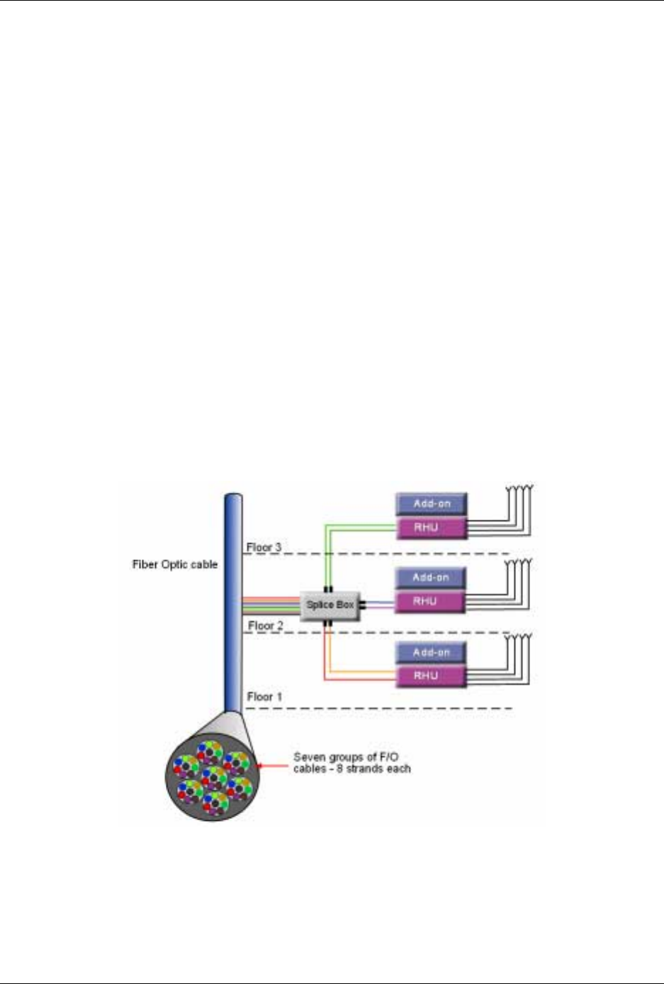
• Fiber optic cable - bundled fibers are terminated into the Base Units in the main
communication room. The fibers are then routed to each coverage location where
individual fibers terminate into splice boxes. The splice box couples the installed
fiber into the remote units. Enough spare fibers should be installed to take into
account future expansion of the system.
For example, for three remote units, six fibers are required. However, to allow for future
upgrades, it is recommended to install additional optic fibers to be connected to
additional RHUs.
The following figure illustrates fiber optic routing sufficient to cover 21 floors: each
group of strands can cover three floors as illustrated below, with two strands to spare.
The first group of strands coves floors 1, 2 and 3; the next group will cover floors 4, 5
and 6 through an additional splice box.
Figure 3-1. Illustration of Fiber Optic Routing

MA 1000 Installation and Configuration Guide
28
• For remote power supply configuration - cable bundles are routed from the
main communication room and individual wire pairs are terminated into the power
feed of individual units.
By providing power from a single distribution point, maintenance can be reduced and
UPS backup can be easily provided. The maximum distance from the source to the
termination spot is 1000 feet using 18 gauge wires.
In many locations local codes do not require power to be run through conduit if 100
watts or less is used. Please consult the regulations in your local jurisdiction prior to
deploying remote power. When power cables require distances greater than 1000 feet
14 or 16 gauge wire may be used.
• On each floor - the antennas are connected to the RHUs using coax cables.

MA 1000 Installation and Configuration Guide
29
4
4
S
Sy
ys
st
te
em
m
I
In
ns
st
ta
al
ll
la
at
ti
io
on
n
4.1 Overview
This chapter describes how the communication room and remote locations are installed. The
individual system elements are described in Chapter 2. In order to describe the installation
process clearly, it will be described as consisting of two logical parts:
A. Telecommunications room – installing the RIUs, BUs, MA 410/430
controllers, and the required
passive equipment
in the telecommunication
room close to the RF signal source. This installation may differ between single
and multi-building topologies.
B. Remote locations – RHU and Add-on installations and connections. These
are
usually
wall mounts.
The installations for two basic topologies are described in detail: for single building and for
multi-building. By understanding the two generic installations you will be able to address
any variations in system deployment.
NOTE: For installations that include the MA NMS: Once the installation has been
completed, it can be verified using the MCT application (NMS User’s Guide) and the devices
monitored using the NMS Manager (NMS User’s Guide).
4.2 Communication Room Installation
NOTE: Usually, each operator installs the equipment that supports their services in a
separate rack.
It is recommended to install the following MobileAccess system modules in a 19” rack in the
communication room
• RIU 3U
• BU 1U
• MobileAccess 410/430 controller 1U
• Fiber Optic patch panel and splice tray
• Power supply/supplies (MobileAccess – 3U for each unit; units from other
manufacturers may vary in size)
MA 1000 Installation and Configuration Guide
30
4.2.1 Rack Installation General Instructions
Verify that the rack height can support all the units to be installed, where you may also
want to consider future expansions.
Figure
4-1 shows the recommended physical location of the MobileAccess elements in the
rack in order to facilitate and simplify the cabling
connections.
The configuration is for a
single operator. If the site is serviced by more than one operator, each operator often
installs their equipment in a separate rack.
NOTE: Note that the MobileAccess 410/430 controller is at eye level to provide an
easy view of the LED indicators and LCD display and easy access to the local and remote
monitoring connections.
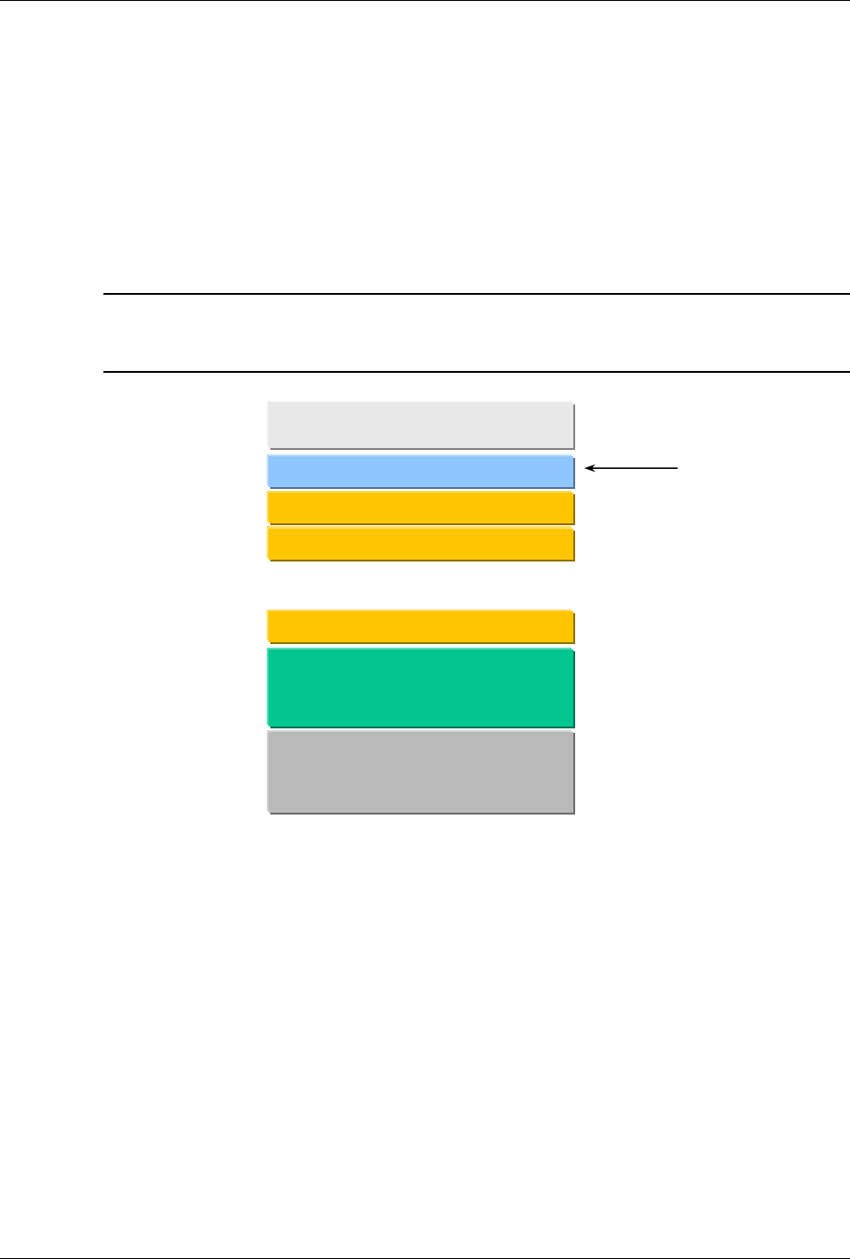
Figure 4-1: Recommended Order in the Communication Room Rack
4.2.2 Rack Installation Safety Instructions
Review the following guidelines to help ensure your safety and protect the equipment from
damage during the installation.
• Only trained and qualified personnel should be allowed to install or replace this
equipment.
• Verify that ambient temperature of the environment does not exceed 50°C (122°F)
• To maintain a low center of gravity, ensure that heavier equipment is installed near
the bottom of the rack and load the rack from the bottom to the top.
MobileAccess Controller (1U)
MobileAccess RIU (3U)
MobileAccess
Power Supply (3U)
Fiber Optic Patch Panel
and Tray
(variable size)
A
t e
y
e level
MobileAccess Base Unit 6 (1U)
MobileAccess Base Unit 1 (1U)
MobileAccess Base Unit 2 (1U)
MA 1000 Installation and Configuration Guide
31
• Ensure that adequate airflow and ventilation within the rack and around the
installed components so that the safety of the equipment is not compromised. It is
recommended to allow for at least about 2 cm of airspace between devices in the
rack.
• Verify that the equipment is grounded as required – especially the supply
connections.
4.2.3 Single Building Rack Installation
This section provides an example of a single building main communication room
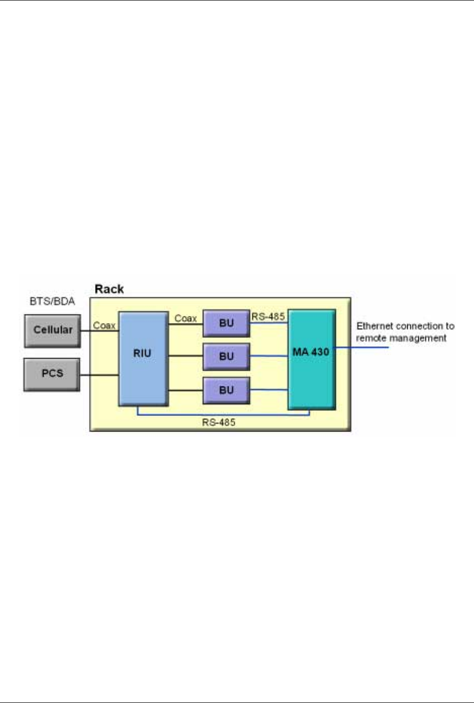
installation for a 24-floor building with Cellular and PCS coverage.
Since there are 24 floors, then 24 MA RHUs are required – one for each floor. In addition,
the following equipment will be installed in the main communication room:
• Three BUs – to support 24 RHUS
• One MA 430 controller for monitoring
• One RIU with Cellular and PCS BTSCs – to interface to the BTS/BDA
Figure 4-2. Example of Single-building Topology Communication Room Installation
MA 1000 Installation and Configuration Guide
32
4.2.4 Multi-Building Rack Installation
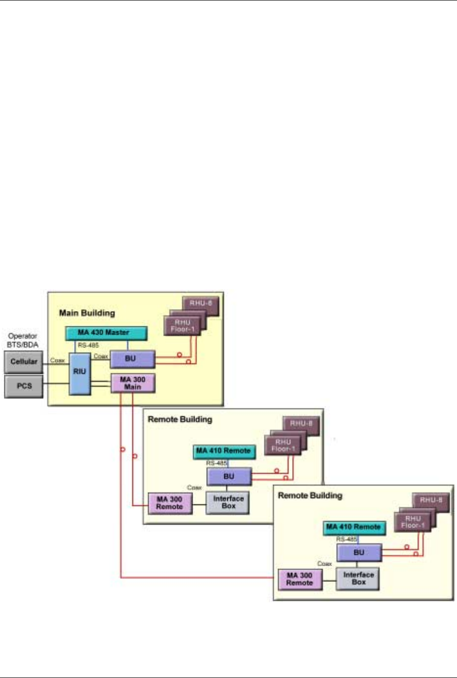
Figure
4-3 provides an example of a multi-building solution which distributes two bands over
a main site and two remote sites. Each site consists of an 8-floor building, requiring 8
RHUS per building (one on each floor).
The following equipment is required in the main communication room of each building:
• One BU – each BU distributes a high-band and low-band signal from a dedicated
operator to eight RHUs (housed in eight separate RCs – one on each floor).
• One MA 430 controller configured as Master in the Main building, and two MA 410
controllers configured as slaves in the Remote buildings.
• MA 300 Main in the main building, and MA 300 Slave in each of the remote
buildings.
The MA 300 units extend the RF signal from the Main to the Remote buildings over a
single strand of fiber. Uplink and downlink signal are placed on the single fiber at 1310 and
1550 respectively.
Figure 4-3. Example of Multi-building Topology Communication Room Installation
MA 1000 Installation and Configuration Guide
33
4.2.5 RIU Connections
4.2.5.1 Basic Connections
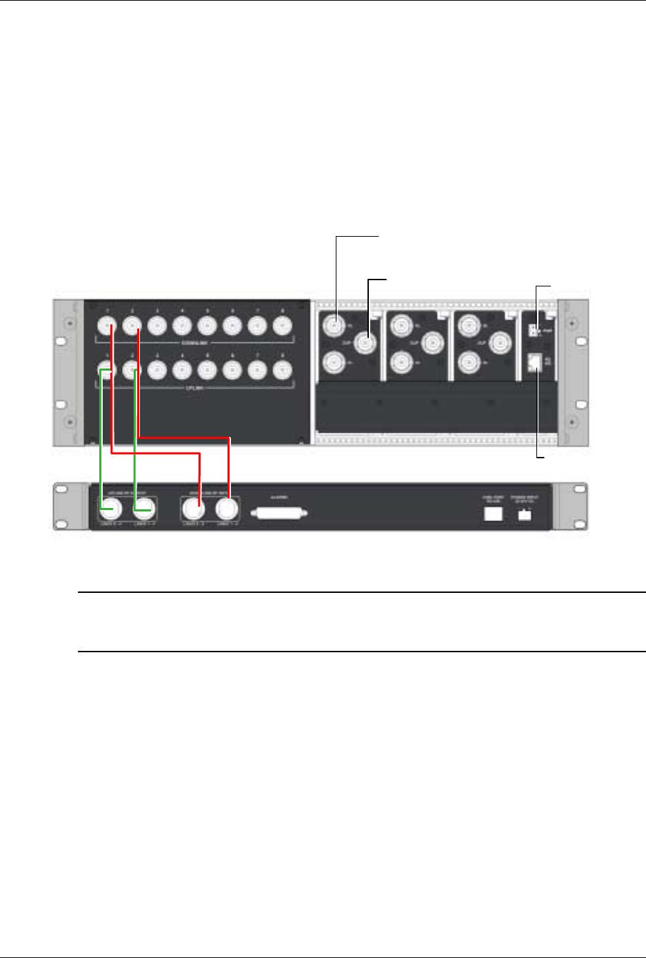
1. Connect each BU to the corresponding RF Uplink and Downlink connectors on the
RIU
rear panel
. Note that
one uplink
and
one downlink
RIU rear-panel ports are used
to connect
one OPTM
(four ports from the BU); two uplink and two downlink ports are
used to connect an 8-port BU (two OPTMs).
Figure 4-4. RIU Rear Panel showing the RF Connection
NOTE: Up to four 8-port BU may be connected. Additional BUs may be connected through
the Extension connector on the front panel. Refer to the following section for instructions
on how to connect to additional BUs.
2. Connect each BTS/BDA to the corresponding rear panel BTSC connectors. For each
BTSC connection, both simplex and duplex connections are available:
• For a duplex connection, connect to the BTSC DUP port;
• For a simplex connection, connect to the BTSC UL and DL ports;
3. Connect the Power connections on the RIU rear panel.
4. If your system includes a MA 410/430 controller, connect the RS485 port on the RIU
rear panel to the controller.
MobileAccess 1000 BU
connections (pair per BU) Power
Controller connection
BTS/BDA duplex
connections
BTS/BDA simplex
connections

MA 1000 Installation and Configuration Guide
34
4.2.5.2 Connections to Additional BUs
To connect more than four 8-port BUs or more than eight 4-port BUs to the RIU, Connect
an 8W splitter to the Downlink connector on the RIU front panel and an 8W combiner to
the Uplink connector on the RIU front panel and connect additional BUs to the uplink and
downlink connections.
Expansion ports
BTSCBTSC
BTSCBTSC
BTSCBTSC
Combiners
/Splitters
Compartment*
UL and DL
connections to
four BU8 modules
UL and DL connections
to up to four additional
BU8 modules
External 1:8 splitter
/combiner
4.2.6 BU Connections
NOTE: It is assumed that the patch panel cabinet (SC/APC adaptors) for fiber optic cable
connections is installed in the rack near the BUs.
1. Connect (3/125/900) pigtail with SC/APC connectors between splice tray and patch
panel cabinet.
2. Connect (3/125/3000) SC/APC jumpers between the corresponding BU and patch
panel.
3. Connect the fiber optic cables from the BU to the RHUs through the patch panel
cabinet.
4. Connect the UL RF Output and DL RF Input connectors to the RIU or UL and DL
connectors or to the passive interface (such as Interface Box) in topologies that do not
include RIUs.
4.2.7 Controller Connections
Refer to the MobileAccess
NMS 410/430 Installation and Configuration Guide
for
connections.
MA 1000 Installation and Configuration Guide
35
4.3 Remote Site Installation
4.3.1 RHU 1000 Installation
Mount and install each RHU on the wall in the communication shaft or communication room.
4.3.1.1 Wall Mount
RHU 1000 is usually mounted on a wall in a clean indoor environment – RF ports facing
down.
Assembly instructions
1. Place the unit against the wall and mark the four holes to be drilled in the wall.
2. Drill four holes 8mm in diameter and insert the appropriate sized plastic plugs in each
hole.
3. Secure the RHU 1000 to the wall using four screws, 4.5mm diameter, 40 mm long.
Figure 4-5. RHU 1000 Wall Mount

MA 1000 Installation and Configuration Guide
36
4.3.1.2 Connections
NOTE: Keep in mind the rules for handling and connecting F/O cables. The F/O cables will
be connected to the associated BU in the communication room at a later phase.
1. Connect fiber optic cable to splice box and to SC/APC pigtails to RHU
2. For the downlink, connect the fiber optic cable pigtails from splice box coming from
the BU port to the corresponding RHU port.
3. Connect the RHU to antennas according to the RF engineers design (up to 4
antennas per RHU).
4. For the uplink, connect the fiber optic cable pigtails from splice box from the RHU to
the uplink port that connects to the BU.
5. Connect the power to each RHU according to power design planning.
6. Verify that 50 ohm terminators are placed on the unused uplink and downlink
connectors.
4.3.2 MA 1200 Add-on Installation
4.3.2.1 Assembly and Connections
Refer to Figure
4-6.
ATTENTION
To prevent damaging the SMA connectors,
be sure to tighten using a torque of 8lb.
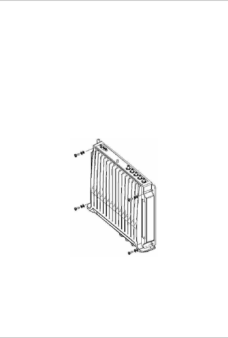
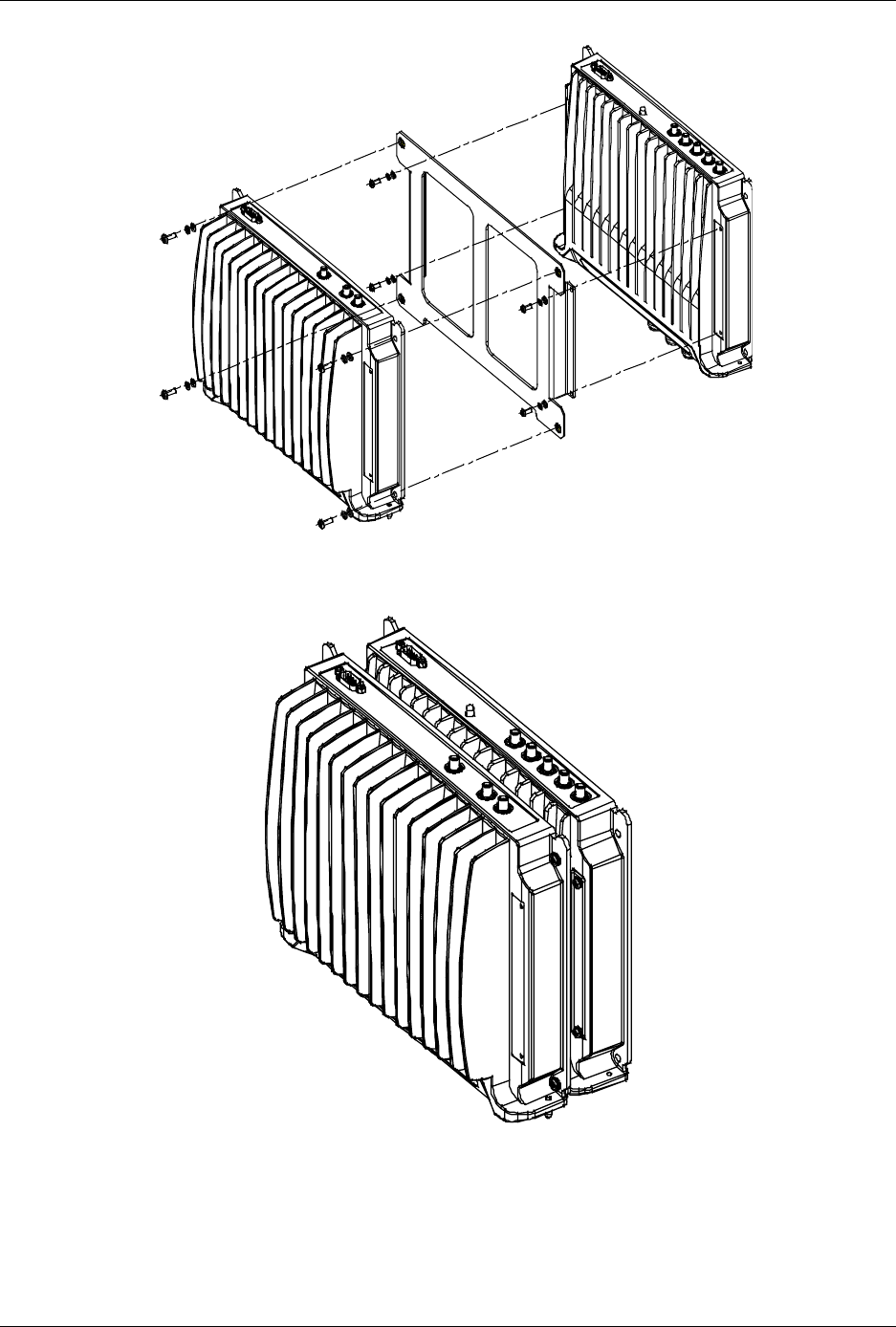
1. Position the supplied bracket on the RHU 1000 and secure the bracket to the RHU
1000 using the four supplied 6-32 NC screws.
2. Position the RHU 1200 unit on the bracket and secure the RHU 1200 to the bracket
using the four supplied 8-32 screws.
3. Interconnect the RHU 1000 and RHU 1200 SMA Uplink, Downlink and High
connectors on the rear panels of both units using the three straight jumpers.
4. Interconnect the RHU 1000 and RHU 1200 D-type 9-pin connectors on the rear
panels of both units using the supplied flat-cable.
5. Connect the power to the RHU 1200 front-panel DC connector.
MA 1000 Installation and Configuration Guide
37
Figure 4-6. RHU 1200 to RHU 1000 Assembly
Figure 4-7. RHU 1200 to RHU 1000 Completed Assembly

MA 1000 Installation and Configuration Guide
38
4.3.3 Antenna Connections
• For systems
without
MA 850 modules - connect the antenna connections to the RHU
antenna ports;
• For systems with MA 850 modules - refer to the
MA 850 Installation and
Configuration Guide
and connect the antenna ports to the MA 850.

39
5
5
A
Ap
pp
pe
en
nd
di
ix
x
I
I:
:
O
Op
pt
ti
ic
ca
al
l
T
Te
es
st
t
P
Pr
ro
oc
ce
ed
du
ur
re
es
s
5.1 General
Two parameters are of prime importance when testing optical cables or jumpers for use
with Mobile Access products:
• Optical Loss – the difference between the optical power at the input and output of
an optical cable. It must be measured (usually in dB units) at 1310 nm. The
maximum allowable loss should be < 0.5 dB/km for Single Mode (SM) cables and <
0.5 dB for every mated pair of connectors.
• Optical Backreflection – the percentage of light backreflected from the fiber
input (dB units). The maximum allowable backreflection should be < –55 dB for all
jumper cables.
The methods to test these parameters will be described below.
5.2 Optical Loss Testing
This section describes the optical loss testing of a Single Mode Cable with SC/APC
connectors at each end.
5.2.1 Required Test Equipment
• 1310 nm Stabilized Laser Source
• 1310 nm Optical Power Meter
• Two Fiber Optic Test Jumpers with SC/APC connectors at each end
• Two SC/APC Adapters
MA 1000 Installation and Configuration Guide
40
5.2.2 Test Procedure
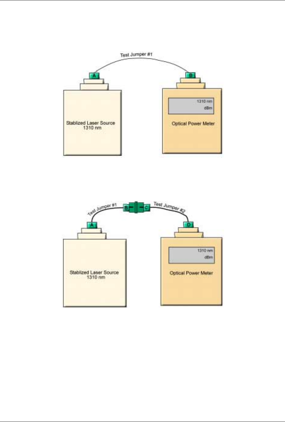
1. Set up the Laser Source, Optical Power Meter, and Test Jumper as shown below.
Figure 5-1. Set Up
2. Record reading as P1 in dBm units.
3. Serially connect the second Test Jumper as shown below.
Figure 5-2. Serial Connection of Second Jumper
4. Record the Power Meter Reading as P2 in dBm units.
5. Calculate Loss L12 according to the equation: L12 = P1 - P2
6. If L12 is lower than 0.5 dB continue to Step-7; otherwise replace these test cables and
repeat from Step-1.
MA 1000 Installation and Configuration Guide
41
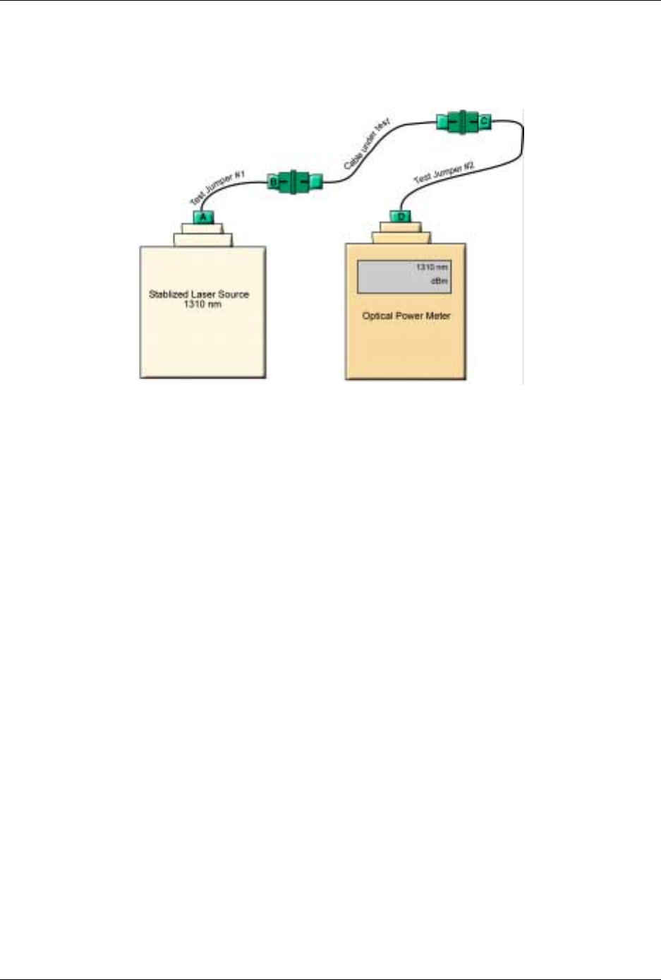
7. Disconnect connectors B and C. Connect the Cable Under Test (CUT)
between connector B and C as shown below.
Figure 5-3. Connecting CUT
8. Record Power Meter reading as Pcut in dBm units.
9. Calculate Cable Loss Ldut from the equation Lcut = P2- Pcut.
10. The maximum allowable loss should be < 0.5 dB/km for SM cables and < 0.5 dB for
every mated pair of connectors.
5.2.3 Example
Testing a 50 meter cable with SC/APC connectors at each end.
• P1 = -1dBm
• P2 = -1.5dBm
• L12= P1 – P2 = -1dBm - (-1.5) = 0.5 dB
Conclusion: the test cables are of sufficient quality to continue testing.
• Pcut = -2dBm
• Lcut = P2 - Pcut= -1.5dBm - (-2dBm) = 0.5 dB
This is acceptable since a mated connector pair was added along with the CUT and a loss of
-0.5 dB is allowed for every mated pair of connectors.
11.
MA 1000 Installation and Configuration Guide
42
5.3 Optical Back-reflection Testing
This section describes the optical back-reflection testing of SM SC/APC connectors at
each end of an optical cable.
5.3.1 Required Test Equipment
1. Adjustable1310 nm Stabilized Laser Source with output power greater
than 7dBm.
2. 1310 nm Optical Power Meter with a measurement range of up to -70
dBm.
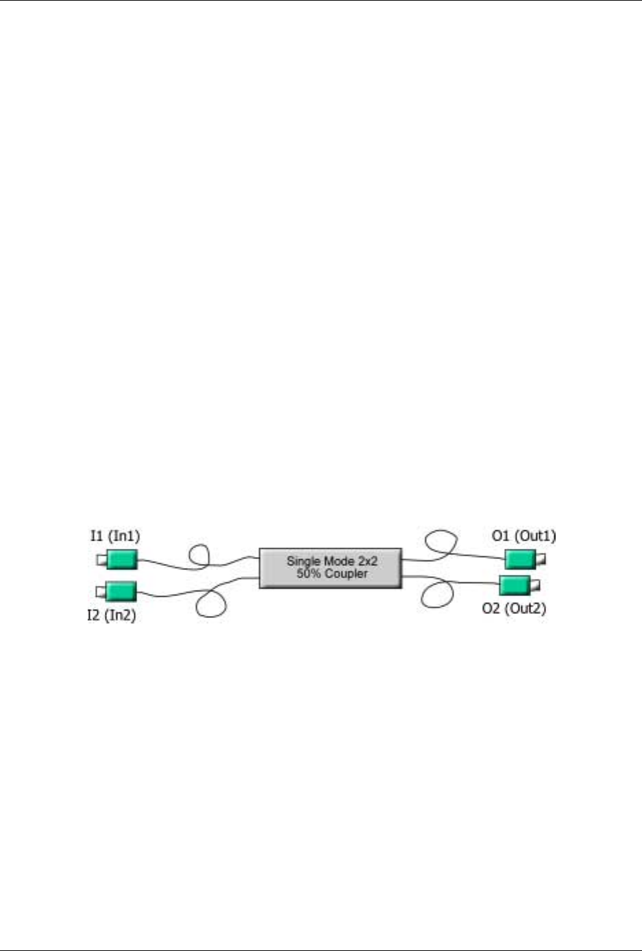
3. One low loss Singlemode 1310 nm 2x2 50%/50% Fiber Optic Coupler
with SC/APC connectors at all four fiber pigtailed ports. Pigtail length
should be 50 cm.
4. One SC/APC Adapter
5.3.2 Test Procedure
1. Refer to the following figure for port definitions of the Fiber Optic
Coupler. The coupler is symmetrical but for our purposes, each port
should be identified as shown in Figure 1-4.
Figure 5-4. Port Identification
2. Measure the loss from port I1 to O1 according to the insertion loss
method described in the previous section. This loss will be referred to
as LI1O1. It should be approximately 3.5 dB.
3. Measure the loss from port O1 to I2 in a similar manner. This loss will
be referred to as LO1I2. It should also be approximately 3.5 dB.
4. Calculate Total Loss, TL where TL= LI1O1 + LO1I2. TL should
approximately 7dB.
5. Adjust the laser output power in dBm to the same value as TL.
For example, if TL = 7dB, adjust the laser output to 7 dBm.
MA 1000 Installation and Configuration Guide
43
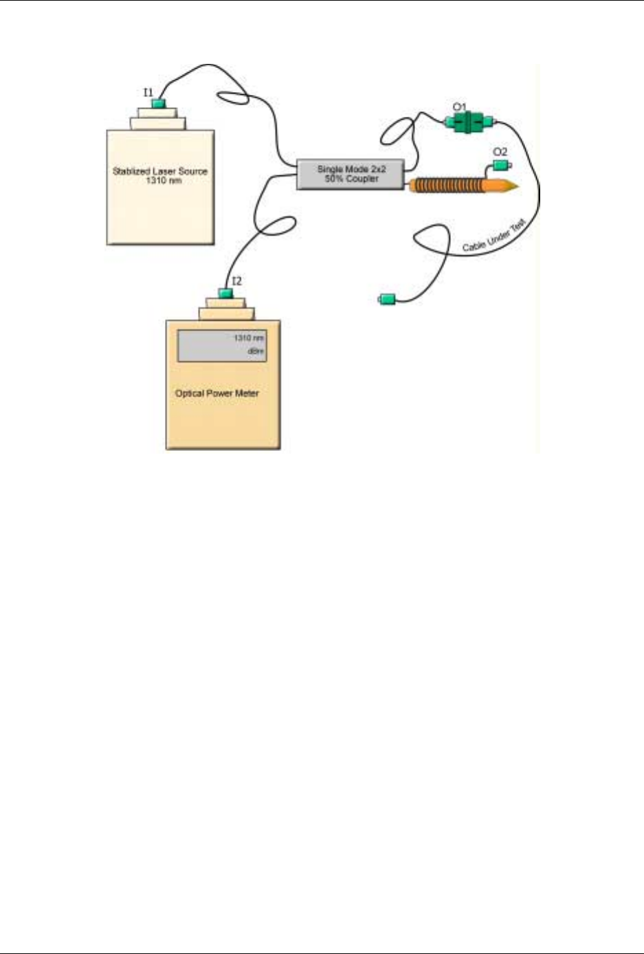
6. Connect the laser to port I1 of the coupler as shown in Figure
5-5.
Figure 5-5. Test Procedure Connections
7. Connect the Power Meter to port I2 of the coupler as shown in Figure
5-5.
8. Wrap the O2 pigtail around a pencil of diameter 7 to 8 mm as
illustrated.
9. The power meter readings should be < –58 dBm; otherwise, clean
connector O1 and measure again.
10. Connect the cable under test to connector O1.
11. Record Power Meter Reading as Backreflection, BRcut, of the cable
under test. The power is measured in dBm units. This is the same
value as the backreflection.
For example, if the power meter shows –58 dBm, the backreflection is –58 dB. The
maximum backreflection from the SC/APC connectors should be < –57 dB.
Long cables will have a higher BR since the cable itself reflects a small amount of light. This
small amount can grow to a considerable amount over a long length of fiber. To factor out
this cable backreflection, perform a mandrel wrap on the cable adjacent to the connector
under test and perform all measurements with the mandrel wrap.