Corning Optical Communication MA1K-SMR-PCS Mobile Telephone In-Building Distribution System User Manual
Corning Optical Communication Wireless Mobile Telephone In-Building Distribution System Users Manual
UserManual.wiki
>
Corning Optical Communication
>
MA1K SMR PCS User Manual
Users Manual
Navigation menu
Upload a User Manual
Namespaces
Wiki Guide
HTML
PDF
Info
Views
User Manual
Discussion / Help
Navigation

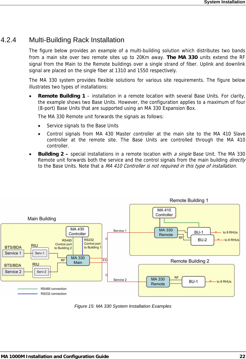
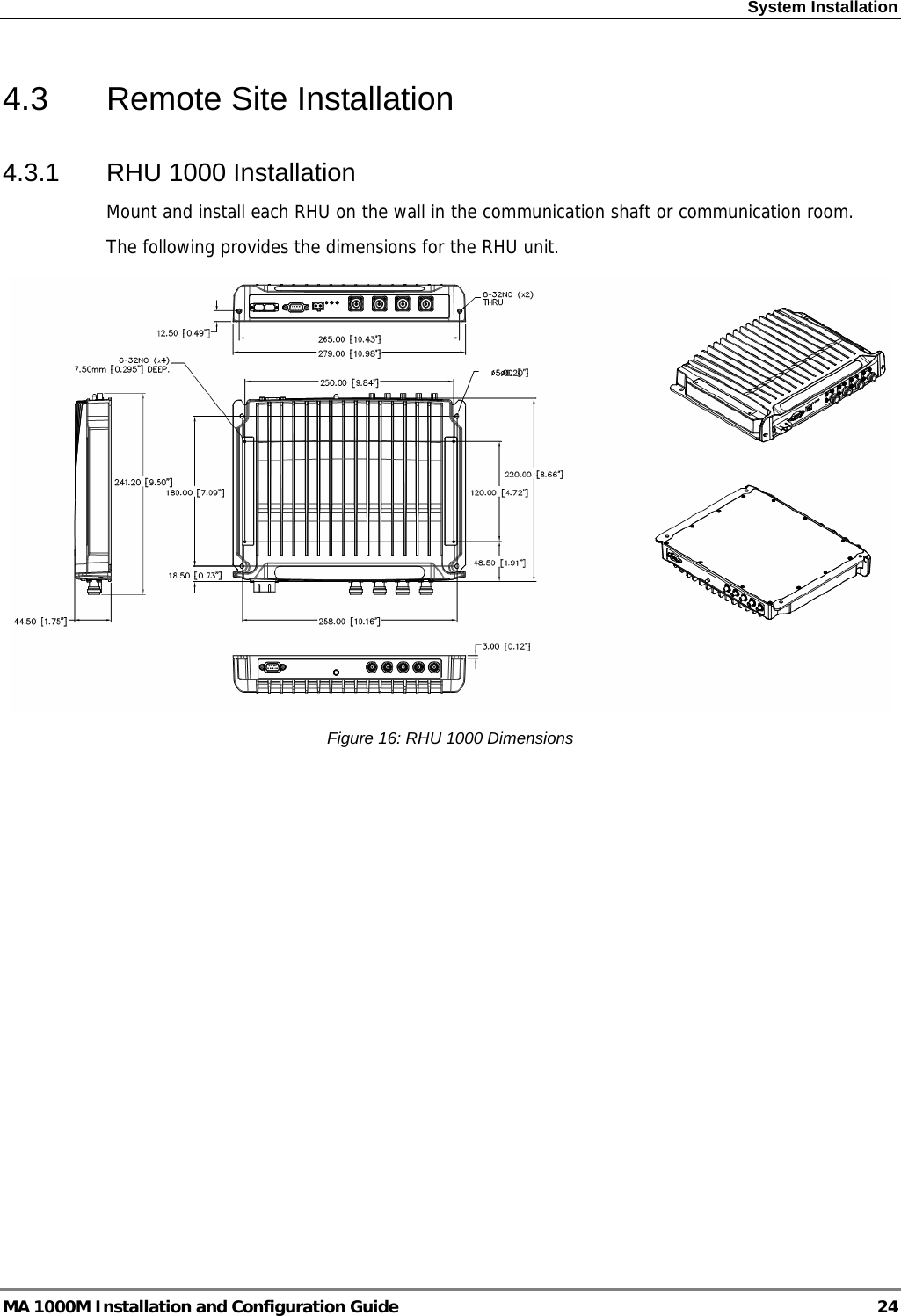
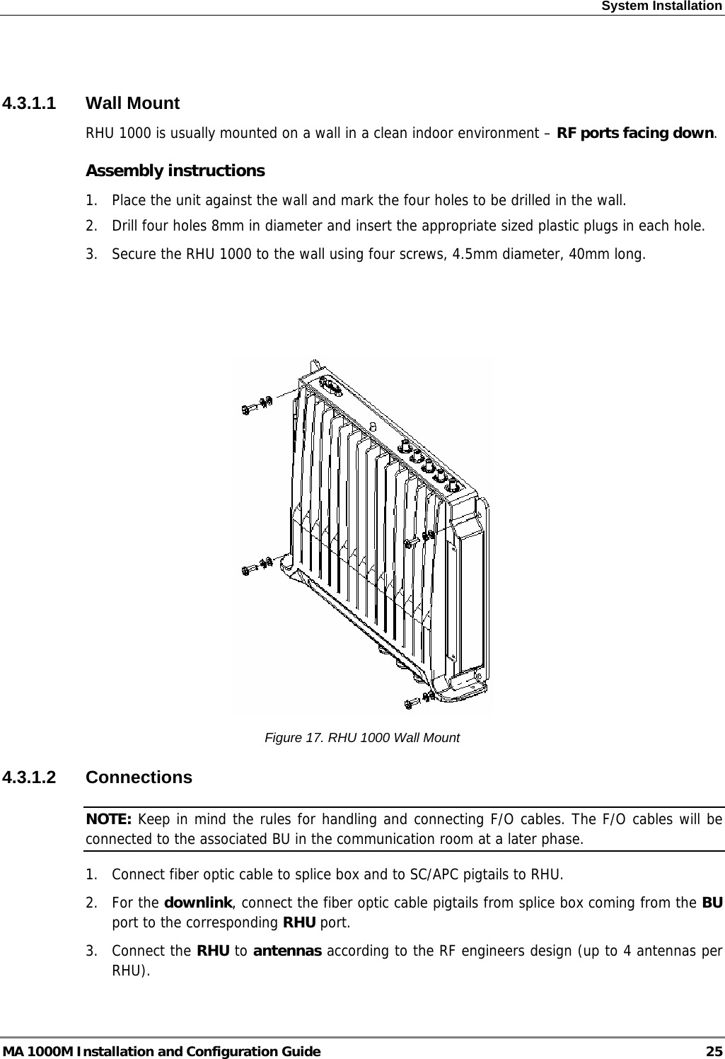

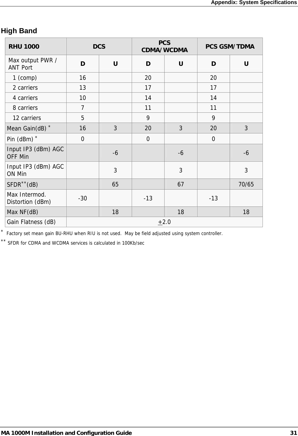
![Appendix: System Specifications RF Parameters 1200 Add-on 1200 Add-on PCS CDMA/WCDMA PCS GSM/TDMA UMTS Max output power per antenna port D U D U D U 1(composite) 20 21 18 2 carriers 17 18 14 4 carriers 14 15 11 8 carriers 11 12 8 12 carriers 9 10 6 Mean Gain(dB)* 20 3 20 3 18 3 Pin (dBm) * 0 1 0 Max. Intermodulation Distortion [dBm] -13/*** -13 *** Input IP3 (dBm) -7 -7 -7 SFDR (dBm)** 66 64 66 Max NF (dB) 18 18 18 Gain Flatness (dB) **** +2.0 *Factory set mean gain BU-RHU when RIU is not used. May be field adjusted using system controller. ** SFDR for CDMA and WCDMA services is calculated in 100Kb/sec ***UMTS and WCDMA complies with 3GPP TS 25.106 V5.0.0 (2002-03) table 9.4 spectrum emission mask **** Gain Ripple is specified for unduplexed port of the system MA 1000M Installation and Configuration Guide 32](https://usermanual.wiki/Corning-Optical-Communication/MA1K-SMR-PCS/User-Guide-983911-Page-40.png)