Corning Optical Communication MA2K-CELL-PCSE RF Booster User Manual Revised
Corning Optical Communication Wireless RF Booster Users Manual Revised
Users Manual Revised

P/N: 709C001202
REV: 1.11
Date: JULY 2006
M
M
Mo
o
ob
b
bi
i
il
l
le
e
eA
A
Ac
c
cc
c
ce
e
es
s
ss
s
s
2
2
20
0
00
0
00
0
0
S
S
Sy
y
ys
s
st
t
te
e
em
m
m
Installation and Configuration Guide


Preface
Preface Material
MA 2000 Installation and Configuration Guide III
P
Pr
re
ef
fa
ac
ce
e
M
Ma
at
te
er
ri
ia
al
l
© COPYRIGHT 2006, MOBILEACCESS NETWORKS INC. ALL RIGHTS RESERVED.
MOBILEACCESSTM IS A REGISTERED TRADEMARK OF MOBILEACCESS. THIS DOCUMENT CONTAINS OTHER TRADEMARKS, TRADE NAMES AND
SERVICE MARKS OF MOBILEACCESS AND OTHER ORGANIZATIONS, ALL OF WHICH ARE THE PROPERTY OF THEIR RESPECTIVE OWNERS.
THIS DOCUMENT CONTAINS CONFIDENTIAL AND PROPRIETARY INFORMATION OF MOBILEACCESS AND MAY NOT BE COPIED, TRANSMITTED, STORED
IN A RETRIEVAL SYSTEM OR REPRODUCED IN ANY FORMAT OR MEDIA, IN WHOLE OR IN PART, WITHOUT THE PRIOR WRITTEN CONSENT OF
MOBILEACCESS. INFORMATION CONTAINED IN THIS DOCUMENT SUPERSEDES ANY PREVIOUS MANUALS, GUIDES, SPECIFICATIONS, DATA SHEETS OR
OTHER INFORMATION THAT MAY HAVE BEEN PROVIDED OR MADE AVAILABLE TO THE USER.
THIS DOCUMENT IS PROVIDED FOR INFORMATIONAL PURPOSES ONLY, AND MOBILEACCESS DOES NOT WARRANT OR GUARANTEE THE ACCURACY,
ADEQUACY, QUALITY, VALIDITY, COMPLETENESS OR SUITABILITY FOR ANY PURPOSE OF THE INFORMATION CONTAINED IN THIS DOCUMENT.
MOBILEACCESS RESERVES THE RIGHT TO MAKE UPDATES, IMPROVEMENTS AND ENHANCEMENTS TO THIS DOCUMENT AND THE PRODUCTS TO
WHICH IT RELATES AT ANY TIME WITHOUT PRIOR NOTICE TO THE USER. MOBILEACCESS MAKES NO WARRANTIES, EXPRESS OR
IMPLIED, INCLUDING, WITHOUT LIMITATION, THOSE OF MERCHANTABILITY AND FITNESS FOR A PARTICULAR PURPOSE,
WITH RESPECT TO THIS DOCUMENT OR ANY INFORMATION CONTAINED HEREIN.

Preface
Preface Material
MA 2000 Installation and Configuration Guide IV
Policy for Warrantee and Repair
MOBILEACCESS TESTS AND INSPECTS ALL ITS PRODUCTS TO VERIFY THEIR QUALITY AND RELIABILITY. MOBILEACCESS USES EVERY REASONABLE
PRECAUTION TO ENSURE THAT EACH UNIT MEETS THEIR DECLARED SPECIFICATIONS BEFORE SHIPMENT. CUSTOMERS SHOULD ADVISE THEIR
INCOMING INSPECTION, ASSEMBLY, AND TEST PERSONNEL ABOUT THE PRECAUTIONS REQUIRED IN HANDLING AND TESTING OUR PRODUCTS. MANY
OF THESE PRECAUTIONS CAN BE FOUND IN THIS MANUAL.
THE PRODUCTS ARE COVERED BY THE FOLLOWING WARRANTIES:
General Warranty
MOBILEACCESS WARRANTS TO THE ORIGINAL PURCHASER ALL STANDARD PRODUCTS SOLD BY MOBILEACCESS TO BE FREE OF DEFECTS IN
MATERIAL AND WORKMANSHIP FOR ONE (1) YEAR FROM DATE OF SHIPMENT FROM MOBILEACCESS. DURING THE WARRANTY PERIOD,
MOBILEACCESS WILL REPAIR OR REPLACE ANY PRODUCT THAT MOBILEACCESS PROVES TO BE DEFECTIVE. THIS WARRANTY DOES NOT APPLY TO
ANY PRODUCT THAT HAS BEEN SUBJECT TO ALTERATION, ABUSE, IMPROPER INSTALLATION OR APPLICATION, ACCIDENT, ELECTRICAL OR
ENVIRONMENTAL OVER-STRESS, NEGLIGENCE IN USE, STORAGE, TRANSPORTATION OR HANDLING.
Specific Product Warranty Instructions
ALL MOBILEACCESS PRODUCTS ARE WARRANTED AGAINST DEFECTS IN WORKMANSHIP, MATERIALS AND CONSTRUCTION, AND TO NO FURTHER
EXTENT. ANY CLAIM FOR REPAIR OR REPLACEMENT OF UNITS FOUND TO BE DEFECTIVE ON INCOMING INSPECTION BY A CUSTOMER MUST BE MADE
WITHIN 30 DAYS OF RECEIPT OF SHIPMENT, OR WITHIN 30 DAYS OF DISCOVERY OF A DEFECT WITHIN THE WARRANTY PERIOD.
THIS WARRANTY IS THE ONLY WARRANTY MADE BY MOBILEACCESS AND IS IN LIEU OF ALL OTHER WARRANTIES, EXPRESSED OR IMPLIED.
MOBILEACCESS SALES AGENTS OR REPRESENTATIVES ARE NOT AUTHORIZED TO MAKE COMMITMENTS ON WARRANTY RETURNS.
Returns
IN THE EVENT THAT IT IS NECESSARY TO RETURN ANY PRODUCT AGAINST ABOVE WARRANTY, THE FOLLOWING PROCEDURE SHALL BE FOLLOWED:
1. RETURN AUTHORIZATION IS TO BE RECEIVED FROM MOBILEACCESS PRIOR TO RETURNING ANY UNIT. ADVISE MOBILEACCESS OF THE MODEL,
SERIAL NUMBER, AND DISCREPANCY. THE UNIT MAY THEN BE FORWARDED TO MOBILEACCESS, TRANSPORTATION PREPAID. DEVICES RETURNED
COLLECT OR WITHOUT AUTHORIZATION MAY NOT BE ACCEPTED.
2. PRIOR TO REPAIR, MOBILEACCESS WILL ADVISE THE CUSTOMER OF OUR TEST RESULTS AND ANY CHARGES FOR REPAIRING CUSTOMER-CAUSED
PROBLEMS OR OUT-OF-WARRANTY CONDITIONS ETC.
3. REPAIRED PRODUCTS ARE WARRANTED FOR THE BALANCE OF THE ORIGINAL WARRANTY PERIOD, OR AT LEAST 90 DAYS FROM DATE OF
SHIPMENT.
Limitations of Liabilities
MOBILEACCESS'S LIABILITY ON ANY CLAIM, OF ANY KIND, INCLUDING NEGLIGENCE FOR ANY LOSS OR DAMAGE ARISING FROM, CONNECTED WITH,
OR RESULTING FROM THE PURCHASE ORDER, CONTRACT, QUOTATION, OR FROM THE PERFORMANCE OR BREACH THEREOF, OR FROM THE DESIGN,
MANUFACTURE, SALE, DELIVERY, INSTALLATION, INSPECTION, OPERATION OR USE OF ANY EQUIPMENT COVERED BY OR FURNISHED UNDER THIS
CONTACT, SHALL IN NO CASE EXCEED THE PURCHASE PRICE OF THE DEVICE WHICH GIVES RISE TO THE CLAIM.
EXCEPT AS EXPRESSLY PROVIDED HEREIN, MOBILEACCESS MAKES NO WARRANTY, EXPRESSED OR IMPLIED, WITH
RESPECT TO ANY GOODS, PARTS AND SERVICES PROVIDED IN CONNECTION WITH THIS AGREEMENT INCLUDING, BUT NOT
LIMITED TO, THE IMPLIED WARRANTIES OF MERCHANTABILITY AND FITNESS FOR A PARTICULAR PURPOSE. MOBILEACCESS
SHALL NOT BE LIABLE FOR ANY OTHER DAMAGE INCLUDING, BUT NOT LIMITED TO, INDIRECT, SPECIAL OR CONSEQUENTIAL
DAMAGES ARISING OUT OF OR IN CONNECTION WITH FURNISHING OF GOODS, PARTS AND SERVICE HEREUNDER, OR THE
PERFORMANCE, USE OF, OR INABILITY TO USE THE GOODS, PARTS AND SERVICE.

Preface
Preface Material
MA 2000 Installation and Configuration Guide V
Reporting Defects
THE UNITS WERE INSPECTED BEFORE SHIPMENT AND FOUND TO BE FREE OF MECHANICAL AND ELECTRICAL DEFECTS.
EXAMINE THE UNITS FOR ANY DAMAGE THAT MAY HAVE BEEN CAUSED IN TRANSIT. IF DAMAGE IS DISCOVERED, FILE A CLAIM WITH THE FREIGHT
CARRIER IMMEDIATELY. NOTIFY MOBILEACCESS AS SOON AS POSSIBLE.
NOTE: KEEP ALL PACKING MATERIAL UNTIL YOU HAVE COMPLETED THE INSPECTION
WARNING: TO COMPLY WITH FCC RF EXPOSURE COMPLIANCE REQUIREMENTS, ANTENNAS USED FOR THIS PRODUCT MUST BE FIXED MOUNTED
ON INDOOR PERMANENT STRUCTURES, PROVIDING A SEPARATION DISTANCE OF AT LEAST 20 CM FROM ALL PERSONS DURING NORMAL OPERATION.
WARNING: ANTENNA GAIN SHOULD NOT EXCEED 10 DB.
WARNING: EACH INDIVIDUAL ANTENNA USED FOR THIS TRANSMITTER MUST BE INSTALLED TO PROVIDE A MINIMUM SEPARATION DISTANCE OF 20
CM OR MORE FROM ALL PERSONS AND MUST NOT BE CO-LOCATED WITH ANY OTHER ANTENNA FOR MEETING RF EXPOSURE REQUIREMENTS.
WARNING: THE DESIGN OF THE ANTENNA INSTALLATION NEEDS TO BE IMPLEMENTED IN SUCH A WAY SO AS TO ENSURE RF RADIATION SAFETY
LEVELS AND NON-ENVIRONMENTAL POLLUTION DURING OPERATION.
ATTENTION:
COMPLIANCE WITH RF SAFETY REQUIREMENTS:
MOBILEACCESS™ PRODUCTS HAVE NO INHERENT SIGNIFICANT RF RADIATION.
THE RF LEVEL ON THE DOWN LINK IS VERY LOW AT THE DOWNLINK PORTS. THEREFORE, THERE IS NO DANGEROUS RF RADIATION WHEN THE
ANTENNA IS NOT CONNECTED.
Laser Safety
FIBER OPTIC PORTS OF THE MOBILEACCESS 2000 EMIT INVISIBLE LASER RADIATION AT THE 1310/1550 NM WAVELENGTH WINDOW.
TO AVOID EYE INJURY NEVER LOOK DIRECTLY INTO THE OPTICAL PORTS, PATCHCORDS OR OPTICAL CABLES. DO NOT STARE INTO BEAM OR VIEW
DIRECTLY WITH OPTICAL INSTRUMENTS. ALWAYS ASSUME THAT OPTICAL OUTPUTS ARE ON.
ONLY TECHNICIANS FAMILIAR WITH FIBER OPTIC SAFETY PRACTICES AND PROCEDURES SHOULD PERFORM OPTICAL FIBER CONNECTIONS AND
DISCONNECTIONS OF THE MOBILEACCESS 2000 MODULES AND THE ASSOCIATED CABLES.
THE MOBILEACCESS 2000 COMPLIES WITH 21 CFR 1040.10 AND 1040.11 EXCEPT FOR DEVIATIONS PURSUANT TO LASER NOTICE NO. 50 (JULY
26, 2001) & IEC 60825-1, AMENDMENT 2 (JAN. 2001).
Care of Fiber Optic Connectors
DO NOT REMOVE THE PROTECTIVE COVERS ON THE FIBER OPTIC CONNECTORS UNTIL A CONNECTION IS READY TO BE MADE. DO NOT LEAVE
CONNECTORS UNCOVERED WHEN NOT CONNECTED.
THE TIP OF THE FIBER OPTIC CONNECTOR SHOULD NOT COME INTO CONTACT WITH ANY OBJECT OR DUST.
REFER TO THE CLEANING PROCEDURE FOR INFORMATION ON THE CLEANING OF THE FIBER TIP.

Preface
Preface Material
MA 2000 Installation and Configuration Guide VI
Safety
WARNING! To comply with FCC RF exposure compliance requirements, antennas used for this product
must be fixed mounted on indoor permanent structures, providing a separation distance of at least
20 cm from all persons during normal operation.
1. Each individual antenna used for this transmitter must be installed to provide a
minimum separation distance of 20 cm or more from all persons and must not be
co-located with any other antenna for meeting RF exposure requirements.
2. The design of the antenna installation needs to be implemented in such a way so as
to ensure RF radiation safety levels and non-environmental pollution during
operation.
Compliance with RF safety requirements:
• MobileAccess™ products have no inherent significant RF radiation.
• The RF level on the downlink is very low at the downlink ports. Therefore, there is no
dangerous RF radiation when the antenna is not connected.

Preface
Preface Material
MA 2000 Installation and Configuration Guide VII
Standards and Certification
MobileAccess products have met the approvals of the following certifying organizations:
ISO 9001
For US: FCC 47 CFT part 22, 24, 90
FDA-CDRH
For Canada: RSS-118, RSS-119, RSS-133….
FCC Certification

Preface
Preface Material
MA 2000 Installation and Configuration Guide VIII
About This Guide
This user guide provides all the information necessary to install and configure the MobileAccess
2000 System.
Revision History
The revision history for this document is shown in Table
1-1.
Table
1-1: Revision history
Version Date Description
1.0 September 2004 Initial version.
1.1 Oct-04 Text editing
1.2 JAN-05 2000 Lite, Configurations, 4x8
1.3 Jan-05 Max current consumption, laser warnings
1.4 FEB-05 Corrected 2000 configurations
1.5 MARCH-05 Modified Remote Cabinet wall-mount assembly to conform to
UL requirements
1.6 APRIL-05 For upgrades, cables interconnecting RU 2000 and MA 1200
add-ons to filters are provided in separate kits. These differ
for Cabinet and for 2000 Lite installations because of cable
length requirements constraints.
1.7 FEB-2006 Digital module.
Updates, reorganization and editing.
1.9 JUNE-06 Addition of section 3.3.4 – Coax Cable lengths and Losses
1.10 JUNE-06 Infrared references removed.
1.11 JULY-06 Laser safety and FCC Safety additions

Preface
Preface Material
MA 2000 Installation and Configuration Guide IX
List of Acronyms
BDA Bi-Directional Amplifier
BTS Base Transceiver Station
BTSC Base Transceiver Station Conditioner
BU Base Unit
DL Downlink
RU Remote Hub Unit
RIU Radio Interface Unit
UL Uplink
VDC Volts Direct Current

Preface
Preface Material
MA 2000 Installation and Configuration Guide X
Table of Contents
Preface Material .........................................................................................................................III
Policy for Warrantee and Repair.......................................................................................................IV
Laser Safety...................................................................................................................................V
Care of Fiber Optic Connectors......................................................................................................V
Standards and Certification.............................................................................................................VII
About This Guide......................................................................................................................... VIII
Revision History........................................................................................................................... VIII
List of Acronyms.............................................................................................................................IX
Table of Contents ............................................................................................................................X
Introduction to the MA 2000 System........................................................................................1
1.1 System Architecture..................................................................................................................2
1.1.1 Head-End Elements..........................................................................................................2
1.1.2 Remote Locations Elements..............................................................................................2
1.1.3 Management Elements.....................................................................................................3
1.1.4 System Operation............................................................................................................4
1.2 Application Example..................................................................................................................5
1.3 MA 2000 Element Models...........................................................................................................6
MA 2000 System Elements........................................................................................................9
2.1 BTS/BDA Side Elements.............................................................................................................9
2.1.1 MA RIU...........................................................................................................................9
2.1.1.1 MA RIU Chassis ................................................................................................. 10
2.1.1.2 RIU Lite............................................................................................................ 13
2.1.2 MA Base Unit................................................................................................................. 15
2.2 MA Remote Location Elements................................................................................................. 17
2.2.1 RU 2000 ....................................................................................................................... 17
2.2.2 MA 1200 Add-on............................................................................................................ 19
2.2.3 MA-850 Module ............................................................................................................. 20
2.2.4 MA 2000 Remote Cabinet............................................................................................... 23
2.2.5 MA 2000 2000 Lite......................................................................................................... 25
2.2.6 8 x 4 Combiner.............................................................................................................. 26

Preface
Preface Material
MA 2000 Installation and Configuration Guide XI
2.3 MA 2000 Remote Management Elements .................................................................................. 27
2.3.1 MA 410/430 Controller ................................................................................................... 29
2.3.1.1 MA 410/430 Controller Front Panel...................................................................... 29
2.3.1.2 MA 410/430 Controller Rear Panel....................................................................... 31
2.3.2 MCT .............................................................................................................................32
Site Preparation .......................................................................................................................33
3.1 Infrastructure Preparation........................................................................................................ 33
3.2 Installation Requirements........................................................................................................ 33
3.3 Coaxial Cable Connections .......................................................................................................34
3.3.1 General Cable Installation Procedures.............................................................................. 34
3.3.2 Fiber Optic Rules ........................................................................................................... 34
3.3.3 RF Rules ....................................................................................................................... 35
3.3.4 Coax Cable Lengths and Losses ...................................................................................... 35
3.4 Power Consumption, Connections and Power Supplies................................................................ 36
3.4.1 Power Safety Instructions............................................................................................... 36
3.4.2 Power Consumption of Units........................................................................................... 36
3.4.3 Circuit Breakers............................................................................................................. 36
3.4.4 Types of Power Supplies................................................................................................. 38
3.5 Installation Conventions .......................................................................................................... 38
System Installation ..................................................................................................................40
4.1 Pre-installation Instructions...................................................................................................... 40
4.1.1 Unpacking and Inspection .............................................................................................. 41
4.2 Communication Room Installation ............................................................................................ 41
4.2.1 Rack Installation General Instructions.............................................................................. 41
4.2.2 Rack Installation Safety Instructions................................................................................ 42
4.2.3 RIU (Chassis) Connections.............................................................................................. 43
4.2.3.1 RIU Connections................................................................................................ 43
4.2.3.2 Connections to Additional BUs............................................................................. 44
4.2.4 BU Connections............................................................................................................. 44
4.2.5 BU and RIU Lite Connections.......................................................................................... 46
4.3 Remote Cabinet Installation.....................................................................................................47
4.3.1 RC 2000 Wall Mount Installation ..................................................................................... 47
4.3.2 RC Grounding - Integrated PS Wall Mount Model.............................................................. 50
4.3.3 RC 2000 Rack Mount Installation..................................................................................... 51
4.3.4 Fiber Optic Connections.................................................................................................. 52
4.3.5 Power Connections ........................................................................................................ 53

Preface
Preface Material
MA 2000 Installation and Configuration Guide XII
4.3.5.1 Integrated Power Supply model .......................................................................... 53
4.3.5.2 External Power Supplies Model............................................................................ 53
4.3.6 Antenna Connections ..................................................................................................... 53
4.4 2000 Lite Installation and Connections...................................................................................... 54
4.4.1 Mounting MA 2000 Lite................................................................................................... 55
4.4.2 Antenna Connections ..................................................................................................... 56
Setup and Adjustment Procedure..........................................................................................57
5.1 Overview................................................................................................................................ 57
5.2 Configuring MA 430 Controller Network Parameters ................................................................... 58
5.3 Opening a Controller Session ................................................................................................... 60
5.4 Base Units Interface Definition.................................................................................................62
5.5 Adjustment Procedure............................................................................................................. 63
Upgrading and Configuration Examples ...............................................................................65
6.1 Common USA Configurations ................................................................................................... 66
6.1.1 iDEN/SMR with PCS Add-on............................................................................................ 66
6.1.2 Cell/PCS........................................................................................................................67
6.2 Common Israeli Configurations................................................................................................. 68
6.2.1 Cell/DCS ....................................................................................................................... 68
6.2.2 Orange/DCS and UMTS Add-on....................................................................................... 69
6.2.3 iDEN............................................................................................................................. 69
Appendix I: Optical test Procedures......................................................................................70
7.1 General.................................................................................................................................. 70
7.2 Optical Loss Testing................................................................................................................ 70
7.2.1 Required Test Equipment ............................................................................................... 70
7.2.2 Test Procedure.............................................................................................................. 71
7.2.3 Example........................................................................................................................ 72
7.3 Optical Back-reflection Testing.................................................................................................73
7.3.1 Required Test Equipment ............................................................................................... 73
7.3.2 Test Procedure.............................................................................................................. 73
MA 2000 Installation and Configuration Guide 1
1
I
In
nt
tr
ro
od
du
uc
ct
ti
io
on
n
t
to
o
t
th
he
e
M
MA
A
2
20
00
00
0
S
Sy
ys
st
te
em
m
MobileAccess 2000 provides a cost effective solution that enables multi-operator indoor coverage
of voice and data wireless services through a single coax antenna infrastructure. MA 2000
provides scalable indoor coverage for enterprises, where support for coverage from additional
operators in any band range, for example CELLULAR 800MHz band and GSM 900MHz band, may
be added as needed, without changing the infrastructure. Thus, subscribers of any operator (for
whom coverage is provided) may have excellent wireless voice reception at any point in the
building, as well as use of the network through 802.11a/b/g data services.
Two types of remote location systems are available:
• 2000 Lite – supports up to 8 services
• 2000 Cabinet – supports up to 20 multi-operator services
The MA 2000 system can be remotely controlled and managed from a single location through MA
410/430 Controllers.
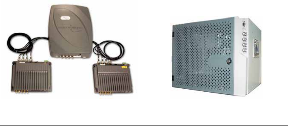
Figure 1-1. MA 2000 Lite (left side) and MA 2000 Cabinet (right side)
MA 2000 Lit
e
MA 2000 Cabine
t

Introduction to the MA 2000 System
System Architecture
MA 2000 Installation and Configuration Guide 2
Features and Capabilities
• Support for all current and future technologies such as TDMA, CDMA, WCDMA and GSM, and
services such as PCS/CELLULAR, Paging, iDEN and 802.11 (a/b/g) Wireless LAN
• Scalable and future-safe – can
easily
be upgraded to provide support for additional services
• Remote end-to-end monitoring through MA 410/430 controllers
• All active components are located in the communication closet/room
• Simple installation and commissioning
1.1 System Architecture
At the head-end, MobileAccess elements provide the interface to the wireless service provider’s
network, condition the signals, convert them from RF to optical and transport them over the
optic fiber infrastructure to the remote end.
At the remote end, MobileAccess elements receive the optical signal transmitted from the head
end, convert the signal back to RF, amplify and filter the signals and then combine them for
distribution over the broadband antenna infrastructure.
Controllers installed at the head-end provide direct interface to the MA elements and through
them, provide end-to-end control over the remote end elements.
1.1.1 Head-End Elements
The following elements are installed at the BTS/BDA side:
• MA Remote Interface Unit (RIU) – Receives and combines RF inputs from one or more
cellular networks via off-the-air repeaters or Base Transceiver Stations (BTS).
NOTE: Interface to the BTS/BDA may also be passive (i.e. Interface Box).
• Base Unit (BU) – Receives the combined signal from the RIU and converts it to an optical
signal for distribution over fiber optic cables to multiple MobileAccess Remote Hubs.
NOTE: These elements are not specific to the MA 2000 system. They are common to other MobileAccess
systems.
1.1.2 Remote Locations Elements
The following elements are installed at each remote location:
• Service specific units that are either housed internally in an MA 2000 Cabinet or connected
externally to an MA 2000 Lite device. Two types of units are available:
• Remote Units (RU) – supports two voice services and performs the optic to RF (and
vice versa) conversion, amplification and filtering at the remote locations. An third
service can be added through connection to an MA 1200 Add-on unit.

Introduction to the MA 2000 System
System Architecture
MA 2000 Installation and Configuration Guide 3
• MA 1200 Add-on – supports a single voice service. It enables a host RU to which it is
connected to provide an additional service.
• MA 850 – flexible and maintainable wireless transport platform that enables large-scale Wi-
Fi deployments and distribution of data services from 802.11a/b/g APs through the same
antennas as the voice services.
• MA 2000 Cabinet – houses up to five units (RUs and MA 1200 add-on), converges the
corresponding services (up to 20) and provides the interface to the coax antenna
infrastructure. (MA 850 can also be added externally)
• MA 2000 Lite – provides connections to two RUs, where MA 1200 add-on units may be
connected to the RUs to provide support for up to 8 services. (MA 850 can also be added).
• Antennas – wideband MobileAccess antennas
1.1.3 Management Elements
The following elements provide remote management for the MA 2000 system elements:
• MA 410/430 Controller – The controller provides the interface between the system
elements and the management and control mechanism.
• MCT – a Java based GUI application provided with both controllers. MCT is used to
setup the system elements and to provide basic management functions.
• MA NMS Manager™ – SEPARATELY PURCHASED APPLICATION. A Java based GUI
software application that provides enhanced monitoring and control capabilities for all
your
MA 430™
sites from a single location.
Introduction to the MA 2000 System
System Architecture
MA 2000 Installation and Configuration Guide 4
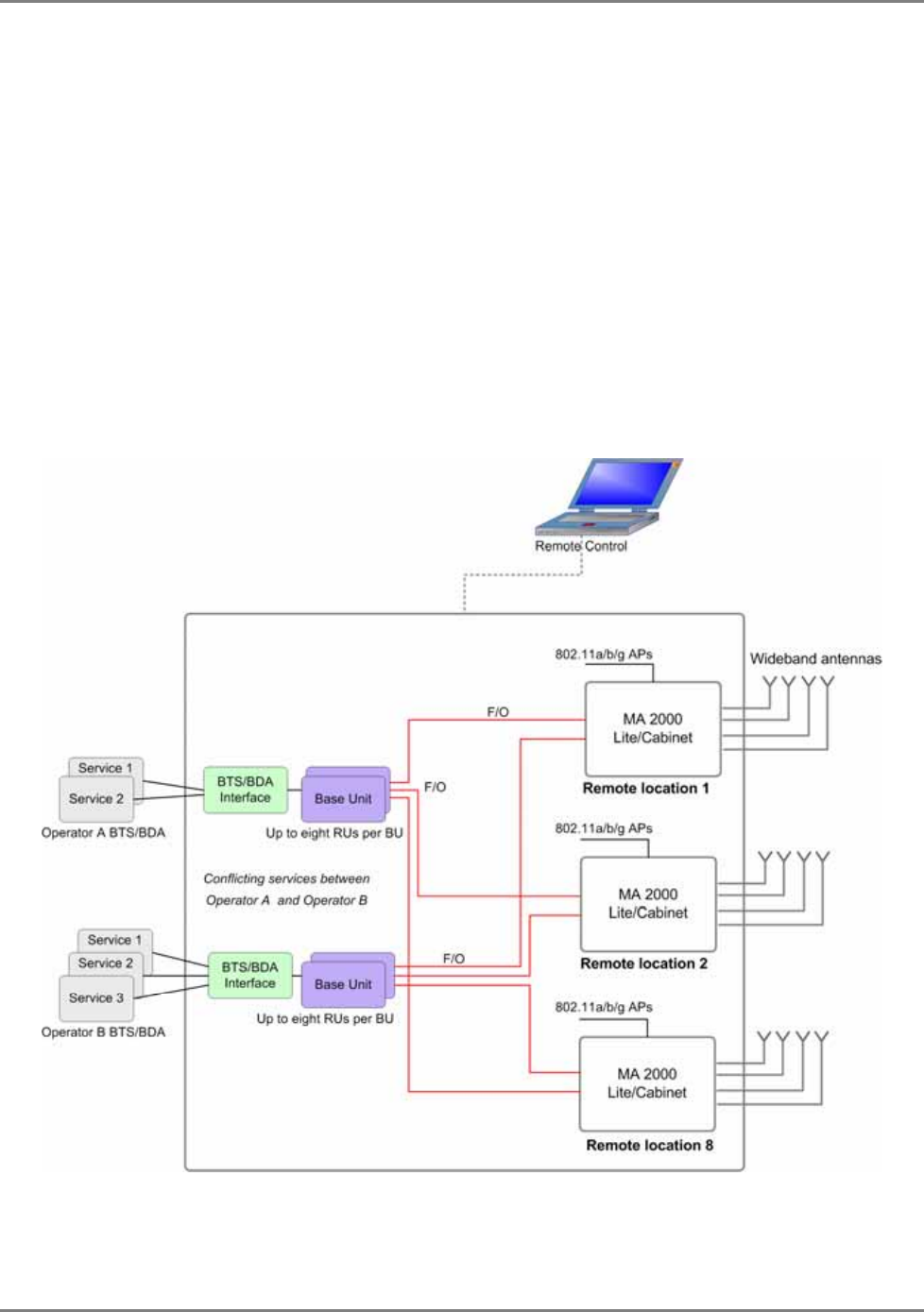
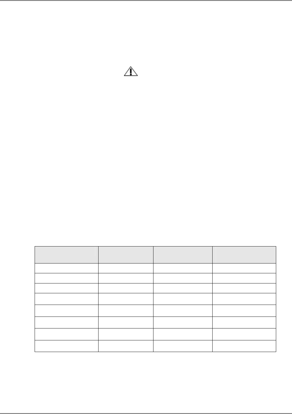
1.1.4 System Operation
Figure 1-2 shows a basic block diagram of the system operation. On the downlink, the services
from the BTS/BDA are transferred via interface to the Base Units. The interface, which may be
passive (i.e. Interface Box) or active (RIU), is used to attenuate the RF signals to the required
levels, converge them and distribute them to the BUs.
The BUs are wideband – they are not
service specific.
At the BUs, the RF signals are converted to optical signals and transmitted over the optic fiber to
(service-specific) RUs at the remote locations. At the remote locations, the RUs, which are either
housed in an MA 2000 Cabinet or externally connected to an MA 2000 Lite, reconvert the optical
signal to RF. At the 2000 Cabinet/Lite, the services are converged and distributed over the coax
antenna infrastructure. Data services from 802.11/a/b/g APs may be integrated into the MA
2000 system at the remote locations. MA 410/430 provide monitoring and control of all active
system elements.
Figure 1-2. Basic Block Diagram of System Operation
Introduction to the MA 2000 System
Application Example
MA 2000 Installation and Configuration Guide 5
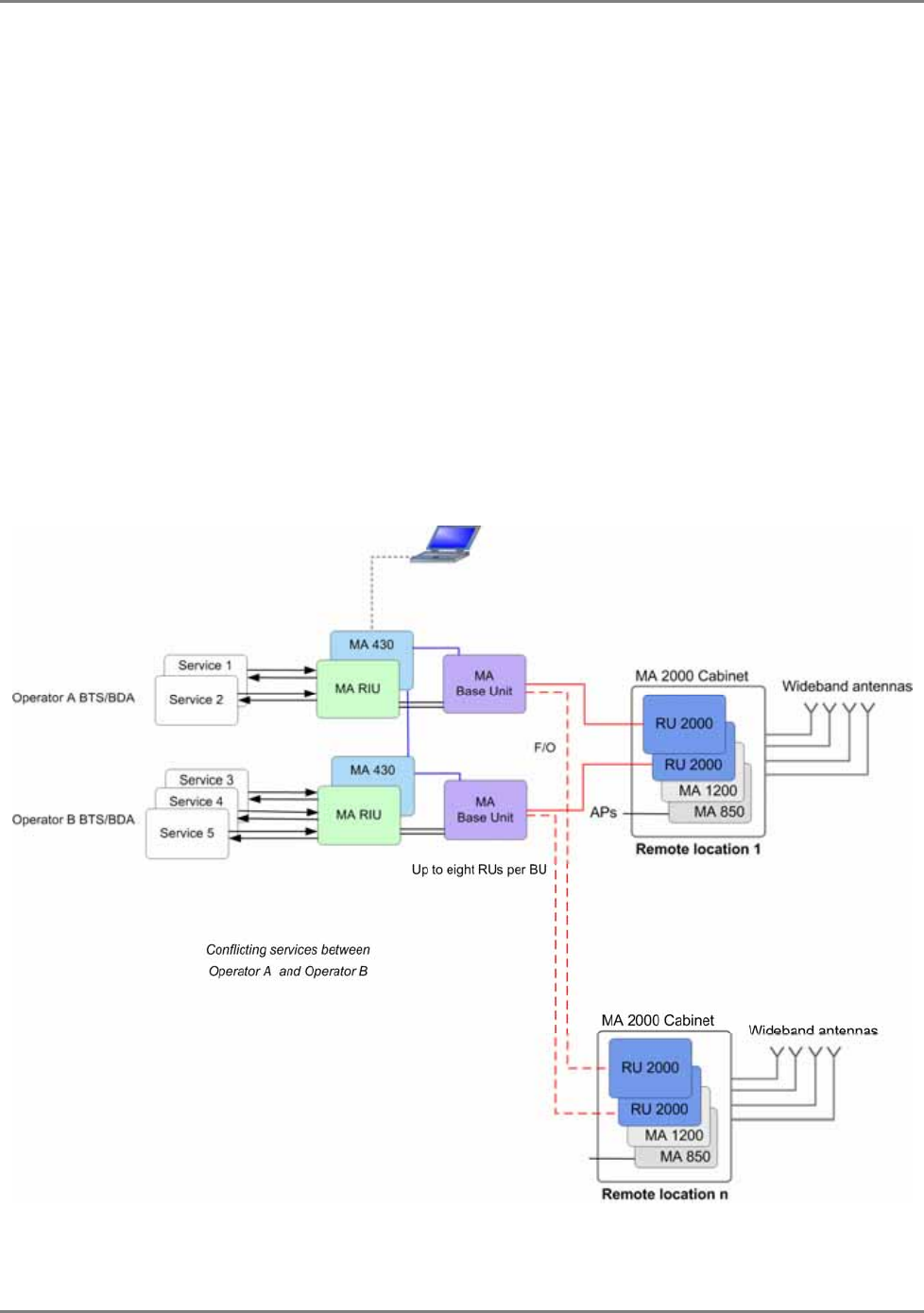
1.2 Application Example
Figure 1-3 shows an example of an MA 2000 Cabinet based solution. Five services from two
different operators are distributed, where services from Operator A conflict with those from
Operator B.
The converted optical signal is routed from the BUs directly to the corresponding RUs in each
Cabinet over optic fiber. Each BU supports connections to 8 RUs. Additional BUs are required for
connection to more RUs.
Services 1 and 2 are distributed through the foremost RU in each Cabinet. Services 3, 4 and 5
are distributed through the second RU and the MA 1200 unit connected to that RU.
MA 850 converges 802.11a/b/g data services with the voice services to be distributed through a
common infrastructure of coax and wideband antennas.
Figure 1-3. Example of MA 2000 Cabinet Architecture
Introduction to the MA 2000 System
MA 2000 Element Models
MA 2000 Installation and Configuration Guide 6
1.3 MA 2000 Element Models
Table
1-1: MobileAccess™ Remote Cabinet Models
MobileAccess Remote Cabinet
2000-RC-RP
2000-RC-LP
2000 - MINI-ENC (Lite)
Remote Cabinet, remote powering – integrated DC power supply
Remote Cabinet, local powering
2000 system supporting two modules (external to the system)
Table
1-2: MobileAccess™ BU Models
MobileAccess Universal Base Units (1000, 1200, 2000 support)
WB-B8U Wide Band Base 8 Unit supporting 8 RUs
WB-B4U Wide Band Base 4 Unit supporting 4 RUs
Table
1-3: MobileAccess™ 2000 RU Models with Add-on Capabilities
Enclosures
2000-RC-RP Remote Cabinet, remote powering
2000-RC-LP Remote Cabinet, local powering
2000-MINI-ENC 2000 enclosure supporting 2 modules
Dual Band RF Modules, add-on ready
2000-CELL-PCSE
2000-IDEN-SMR
2000-CELL-DCSE
2000-GSM-DCSE
2000-GSMO-DCSE
2000-GSM-DCSE-I
2000-CELL-PCSE-I
2000-CELL-PCSE-L
2000-IDEN-SMR -L
2000-CELL-DCS-L
2000-GSMO-DCSE-L
2000-GSM-DCSE-L
2000-GSM-DCSE-IL
2000-CELL-PCS-IL
- Dual Band Cell/PCS for cabinet
- Dual Band iDEN/SMR for cabinet Nextel
- Dual Band Cell/DCS for cabinet
- Dual band GSM/DCS for cabinet
- Dual band GSM Orange/DCS for cabinet
- Dual Band Cell/DCS for cabinet Indonesia
- Dual Band Cell/PCS for cabinet Indonesia
- Dual Band Cell/PCS for Lite
- Dual Band iDEN/SMR for Lite Nextel
- Dual Band Cell/DCS for Lite for Lite
- Dual Band GSM/DCS for Lite
- Dual Band GSM Orange/DCS for Lite
- Dual Band Cell/DCS for Lite Indonesia
- Dual Band Cell/PCS for Lite Indonesia
Introduction to the MA 2000 System
MA 2000 Element Models
MA 2000 Installation and Configuration Guide 7
MobileAccess 1200 RHUs
1200-PCS-AO-CB
1200-UMTS-AO-CB
1200-PCS-AO-LT
1200-UMTS-AO-LT
- Add-on RHU - PCS service for cabinet
- Add-on RHU - UMTS service for cabinet
- Add-on RHU - PCS service for Lite
- Add-on RHU - UMTS service for Lite
* NOTE: An accessory kit must be ordered for each new RU 2000, where the number of accessory kits
are equal the number of RUs (i.e. three accessory kits for three RUs). If the RU is to be installed in a
Cabinet, the AK-2000-CABINET accessory kit is required. If the RU is to be installed in a 2000 Lite model,
the AK-2000-LITE accessory kit is required.
Table
1-4: MobileAccess™ 1200 Add-on Models
MA 1200 Add-on
1200-PCS-AO Add-on RU - PCS service
1200-UMTS-AO Add-on RU - UMTS service
AK-1200-LITE* Accessory kit for 1200 RU installed in 2000 Lite
AK-1200-CABINET* Accessory kit for 1200 RU installed in 2000 Cabinet
* NOTE: An accessory kit must be ordered for each new 1200 Add-on, where the number of accessory
kits are equal the number of Add-ons (i.e. two accessory kits for two Add-ons). If the 1200 Add-on is to be
installed in a Cabinet, the AK-1200-CABINET accessory kit is required. If the 1200 Add-on is to be installed
in a 2000 Lite model, the AK-1200-LITE accessory kit is required.
Table
1-5: MobileAccess™ Controller Models
Network Controller
410 Network Controller – Serial Interface (dial-up)
430 Network Controller – Ethernet/IP Interface
Table
1-6: MobileAccess™ Management System
Network Management System
NMS-SW-SERVER GUI and server S/W package (one per site)
NMS-SW-MFEE NMS annual S/W maintenance fee (per 430-CTLR)

Introduction to the MA 2000 System
MA 2000 Element Models
MA 2000 Installation and Configuration Guide 8
Table
1-7: MobileAccess™ RIU
MobileAccess Radio Interface Unit (RIU)
RIU-IM
RIU-BTSC-CELL
RIU-BTSC-IDEN
RIU-BTSC-PCS
RIU-BTSC-SMR
RIU-BTSC-GSM
RIU-BTSC-GSM-O
RIU-BTSC-DCS
RIU-BTSC-UMTS
RIU-BDAC-CELL
RIU-BDAC-IDEN
RIU-BDAC-PCS
RIU-BDAC-SMR
RIU-BDAC-GSM
RIU-BDAC-GSM-O
RIU-BDAC-DCS
RIU-L-ESMR-SMR1
RIU-L-CELL-PCS1
Radio Interface Unit
BTS Conditioner for Cellular
BTS Conditioner for iDEN
BTS Conditioner for PCS
BTS Conditioner for SMR-Paging
BTS Conditioner for GSM 900MHz
BTS Conditioner for GSM 900MHz for Orange
BTS Conditioner for DCS 1800MHz
BTS Conditioner for UMTS 2100MHz
BDA Conditioner for Cellular
BDA Conditioner for iDEN
BDA Conditioner for PCS
BDA Conditioner for SMR-Paging
BDA Conditioner for GSM 900MHz
BDA Conditioner for GSM 900MHz for Orange
BDA Conditioner for DCS 1800MHz
RIU Lite ESMR 800,SMR 900
RIU Lite Cellular 800,PCS 1900

MA 2000 Installation and Configuration Guide 9
2
M
MA
A
2
20
00
00
0
S
Sy
ys
st
te
em
m
E
El
le
em
me
en
nt
ts
s
This chapter provides a full, detailed description of each of the system elements and their
individual connections. The element descriptions are organized in three sections:
• Head end - BTS/BDA Side Elements
• Remote Location Elements
• Setup and Management Elements
2.1 BTS/BDA Side Elements
The following MobileAccess 2000 system elements are installed on the BTS/BDA side:
NOTE These elements are common to both MA 1000 and MA 2000 systems.
• MA RIU – provides active interface and control of the RF signal sources
• Base Units – perform the RF to optical (and vice versa) on the BTS/BDA side
2.1.1 MA RIU
NOTE: This section provides a brief description of the RIU devices, and the front and rear panel
connections for each device. For full, detailed descriptions, refer to the RIU Product Line Installation and
Configuration Guide.
The RIU is a service specific device that provides interface between the BTS/BDA systems and
the Base Units. The RIU enables controlling and monitoring the signals level to provide optimum
site coverage. RIU setup and adjustment is performed through a point-to-point connection and
the MCT application supplied with the controller.
MA 2000 System Elements
BTS/BDA Side Elements
MA 2000 Installation and Configuration Guide 10
RIUs provide interface to each BTS/BDA through internally installed sub-modules corresponding
to the RF signal source (BTS or BDA) and the service band. Two main types of sub-modules are
available:
• BTSC (BTS Conditioner) - BTS service specific modules
• BDAC (BDA Conditioner) – BDA service specific modules
Two types of RIUs are available:
• RIU Chassis
• RIU Lite
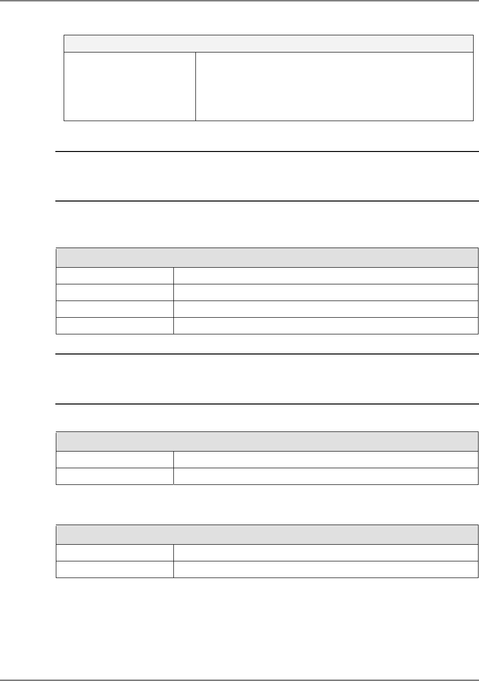
2.1.1.1 MA RIU Chassis
MA RIU Chassis is a
scalable
device with the following main capabilities:
• Support for up to three BTS and BDA services in any combination
• Duplex and simplex BTS/BDA interface for each service
• Support for up to four 8-port BUs, where the number of BUs can be doubled using an
Extension
• Front panel indicators per service module
• Setup and monitoring using MCT via a local RS232 or a dial-up connection
• Setup and monitoring using the MCT software application and connection to the host MA
410/430 controller
• 3U 19” rack-mountable device with an integrated power supply.
Figure 2-1. RIU Chassis with Three Sub-modules
MA 2000 System Elements
BTS/BDA Side Elements
MA 2000 Installation and Configuration Guide 11
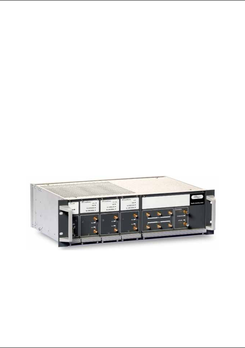
RIU Chassis Front Panel
The RIU front panel contains the indicators for each of the sub-modules (BTSC/BDAC) installed
in the device and for the power supply. In addition, the front panel contains Expansion
connectors for interface to additional BUs (if interface to more than four 8-port BUs is required).
Figure 2-2. RIU Front Panel
Table
2-1. RIU Front Panel Indicators
LED Description
P.S UNIT PWR ON – input power is at the required level.
BTS CONDITIONER RUN Flashing -- CPU is running and software loaded
BTS CONDITIONER DL
OVERLOAD Continuous Red – RF output towards BUs is disconnected to protect the
system. This may be due to:
o Unpredicted power rise for which the attenuation response was
insufficient to compensate and reduce the power to the required level.
o Software problem detected.
Flashing: When the BTSC DL output power exceeds the calibrated value.
BTS CONDITIONER DL
LOW Continuous Red – if the RF outputs towards the BU is lower than the calibrated
value. This condition also triggers an event.
Power Supply BTS/BDA Conditioners Expansion connectors - for
connecting additional BUs
MA 2000 System Elements
BTS/BDA Side Elements
MA 2000 Installation and Configuration Guide 12
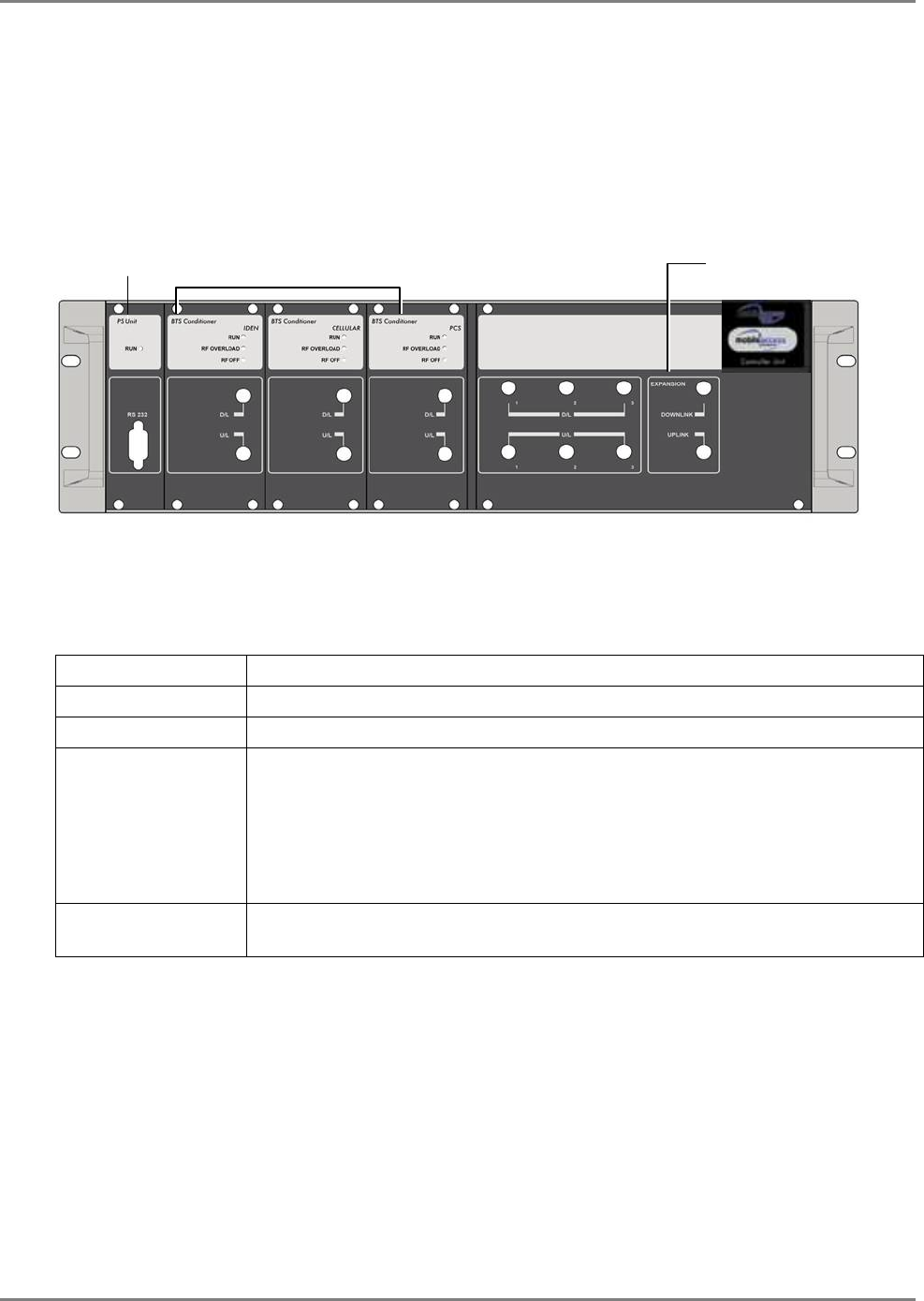
RIU Rear Panel
The rear-panel contains connections to the BTS/BDA devices, BUs, Controller and Power.
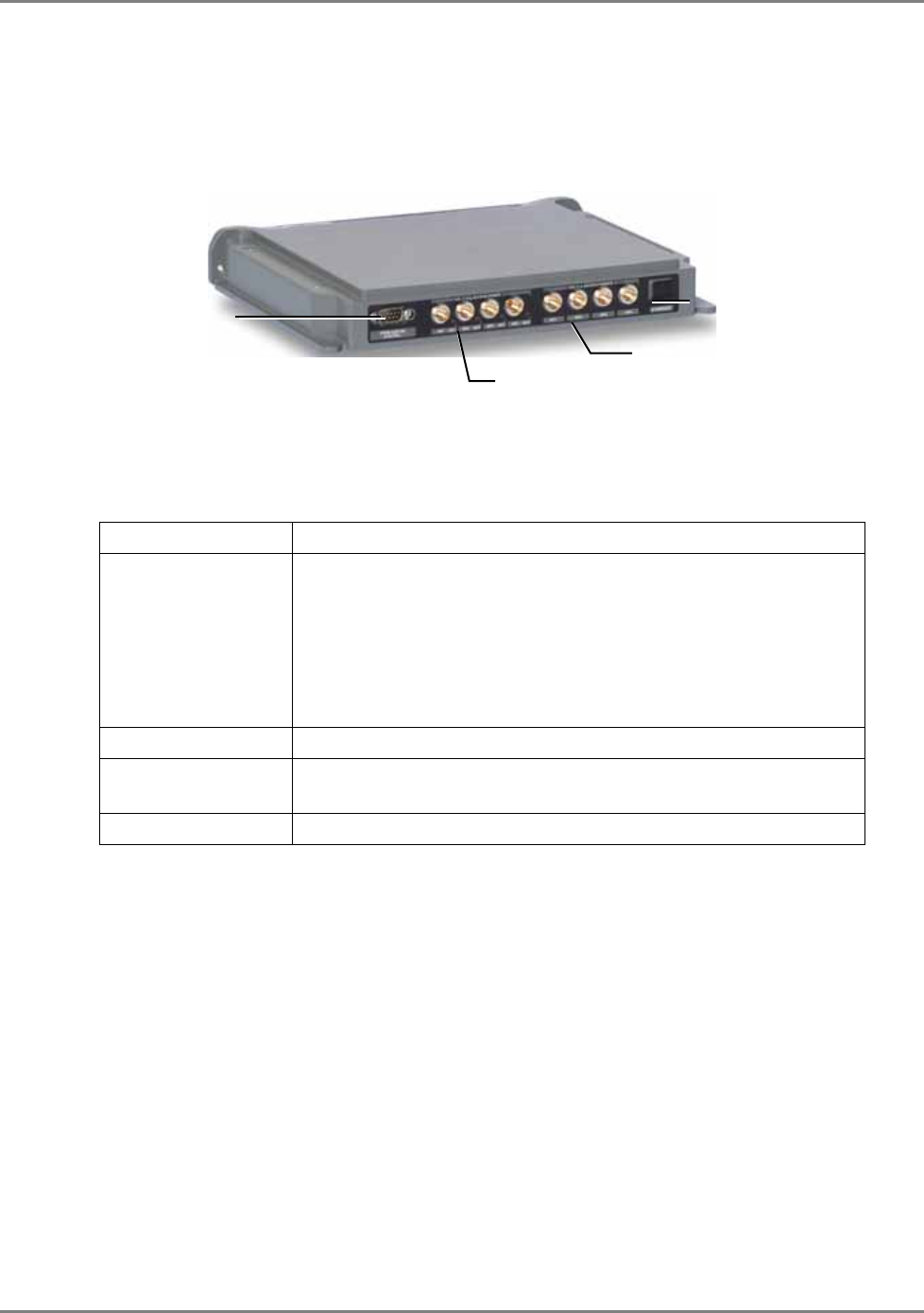
Figure 2-3. RIU Rear Panel showing the RF Connection
Table 2. RIU Rear Panel Connectors
Connector Description
UL/DL and DUPLEX BTS interface (via BTSC) - UL/DL and Duplex
BDA interface (via BDAC) – Duplex interface only
BU UPLINK/DOWNLINK BU UL/DL connections, where an 8-port BU consists of two modules and
therefore would require two pairs UL and DL connections.
RS485 MA 410/430 controller connection. Connects to the controller rear panel
RS485 connector (either port 1 or 5 on the controller).
PWR DC power connection – 20 to 48 VDC
BU connections; one UL and one DL
connection for every group of four
ports (single OPTM) on the BU. Power
MA Controller
connection
BTS/BDA
sim
p
lex
BTS/BDA duplex
connections
MA 2000 System Elements
BTS/BDA Side Elements
MA 2000 Installation and Configuration Guide 13
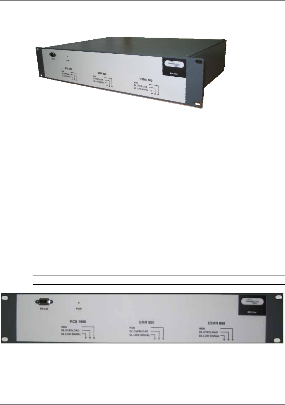
2.1.1.2 RIU Lite
Figure 2-4. RIU Lite – Support for Three Services
MA RIU Lite is factory defined with the required services. It provides the following main
capabilities:
• Support for up to three BTS and BDA services in any combination
• Support for duplex and simplex BTS/BDA interface
• Support for up to four 8-port BUs, where the number of BUs can be doubled using an
extension
• Front panel LEDs per BTSC/BDAC unit
• Setup and monitoring using the MCT software application and connection to the host MA
410/430 controller
• 3U 19” rack-mountable device with an integrated power supply.
RIU Lite Front Panel
The RIU Lite front panel contains LED indicators for each service and an RS232 connection for
MA service personnel.
NOTE: The RS232 service connector is for the use of MA Service Personnel.
Figure 2-5. RIU Lite Front Panel
MA 2000 System Elements
BTS/BDA Side Elements
MA 2000 Installation and Configuration Guide 14
Table 2-2 2. RIU Front Panel LEDs
LED Description
PWR ON – input power is within the required range
RUN A set of LEDs is provided for each service supported by the RIU.
Green Flashing – corresponding BDAC module is operational
DL Overload
Red – DL RF input is disconnected due to:
Input
power exceeding maximum allowed level
Software setting
Red Flashing: DL RF
output
exceeds the maximum allowed value.
DL Low Signal DL power is under the minimum required level
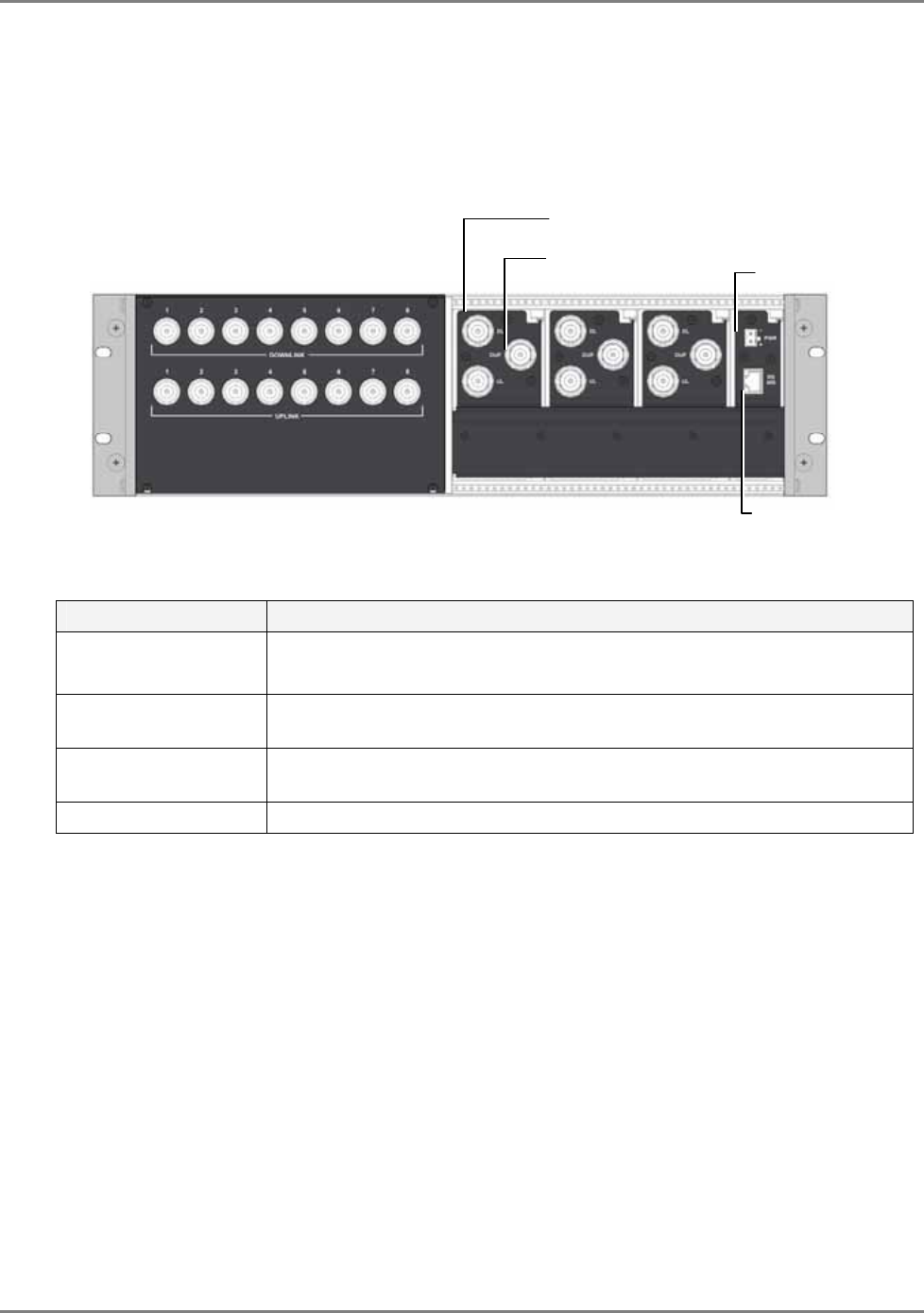
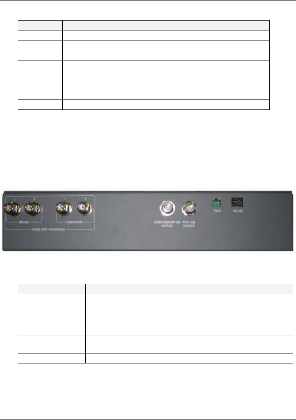
RIU Lite Rear Panel
The RIU rear-panel contains the RF, control and power connections. The BDA side connections
correspond to the number of installed modules. The following figure shows an example of an
RIU model supporting two BDAs.
Figure 2. RIU Lite Rear Panel
Table 2. RIU Rear Panel Connectors
Connector Description
CELLULAR/PCS DUP Duplex connections to BDA services.
UPLINK/DOWNLINK Base Unit connections. Each pair of UL/DL connections (i.e. Uplink 1 and
Downlink 1) connects to the corresponding RF connections on a Base Unit
module, where an 8-port BU consists of two modules and therefore would
require two pairs of connections.
RS485 Connections to MA 410/430 controller rear panel RS485 connector (either
port 1 or 5 on the controller)
PWR DC power connection – 20 to 48 VDC
Service connections Control connectionBU connections Power
MA 2000 System Elements
BTS/BDA Side Elements
MA 2000 Installation and Configuration Guide 15
2.1.2 MA Base Unit
The BU (Base Unit) is a wideband device that performs RF to optical (and vice versa) conversion
of the signal on the BTS/BDA side. The BU interfaces to the RIU (or to passive BTS/BDA
interface) and the optic fiber.
Two models of MA BUs are available:
• Four-port unit – supports optic connections to four RUs
• Eight-port unit – supports optic connections to eight RUs
About OPTMs:
Each 4-port unit is referred to as OPTM. An 8-port unit consists of two 4-port modules or two
OPTM, as they are referred to.
NOTE: Each 4-port module is referred to as OPTM and separately managed in the MCT and NMS
management applications.
BU capabilities:
• Supports all services distributed by MobileAccess systems
• Fiber connection to up to 8 RUs
• Setup and monitoring through connection to the host MA 410/430 controller and MCT
software application
• Dry contact alarms
• Front panel indicators providing status on optical link internal circuitry and signal level
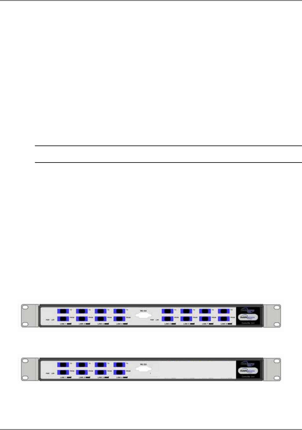
MA BU Front Panel
The front panel contains the optical connections and indicators. Each four-port element has a
dedicated set of indicators (PWR, LSR and Link 1 to Link 4 or Link 5 to Link 8).
Figure 2-6. Eight-Port MA BU Front Panel
Figure 2-7. Four-Port BU Front Panel
Four ports and corresponding indicators Four ports and corresponding indicators
MA 2000 System Elements
BTS/BDA Side Elements
MA 2000 Installation and Configuration Guide 16
Table
2-3. MA BU Front Panel Indicators
LED Description
PWR Power input detected for the corresponding unit.
LSR ON - laser circuitry for the corresponding element (group of four ports) is
functioning correctly.
Link 1-4, 5-8 ON - the optical link to/from the connected remote functions within the
specifications in both directions.
Blinking - optical power from remote is lower than required
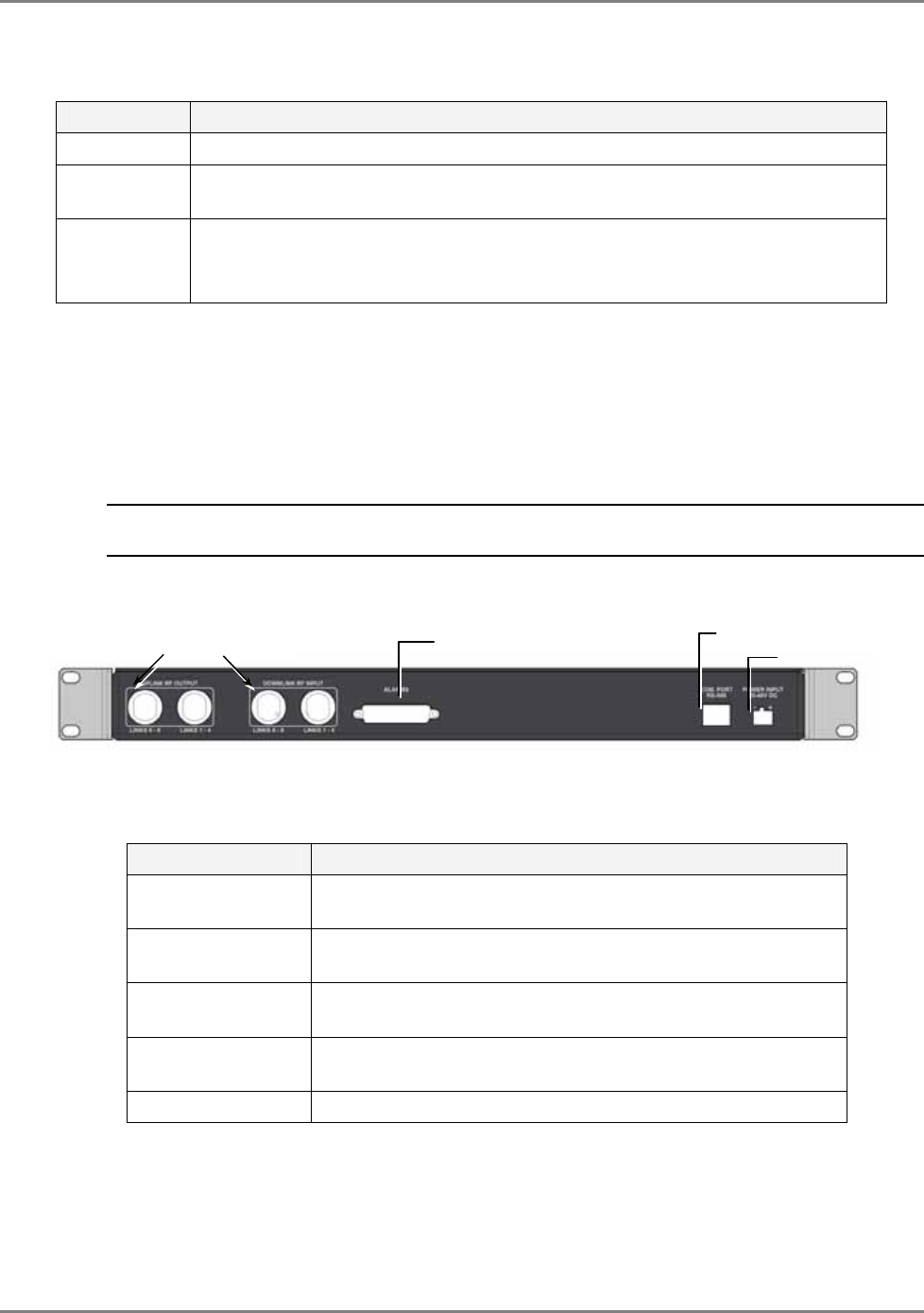
BU Rear Panel
The BU rear panel contains the RF connections, Alarms, NMS and power connections.
NOTE: The following figure shows the rear panel of an 8-port BU. A 4-port BU contains a single UL and a
single DL RF connector.
Figure 2-8. MA BU Rear Panel (RF Connections)
Table
2-4. MobileAccess 1000 Rear Panel Connections
Connector Description
Uplink output Uplink connectors to be connected on BTS/BDA side. For an
8-port BU, both UL connectors must be connected.
Downlink input Downlink connectors to be connected on the BTS/BDA side.
For an 8-port BU, both DL connectors must be connected.
Com Port RS485 Connection to MobileAccess 410/430 controller, rear panel
RS485 port.
Alarms Dry-contact connections to BTS/BDA (normally closed).
Relevant only for system without MA 410/430 controllers.
PWR Power connection: 20 to 48VDC
Pair of uplink and downlink RF
connections for interface to BTS Alarms dry-
contact
t
MA 410/430
Power

MA 2000 System Elements
MA Remote Location Elements
MA 2000 Installation and Configuration Guide 17
2.2 MA Remote Location Elements
Service specific units located at each remote location convert the RF signals to optics and route
them to the coax antenna infrastructure. In addition, 802.11 data services may be added for
distribution at each remote location. The units are either housed in, or externally connected to, a
device or ‘enclosure’ that converges the data and voice services and provides the common
interface to the antennas.
The following types of service specific elements are available:
• Remote Units (RUs) – support two voice services
• MA 1200 Add-on – used to add an additional (third) service to the RU.
• MA 850 – converges data services from 802.11a/b/g APs
Two types of enclosures are available for the service specific elements at each remote location:
• 2000 Lite – supports up to 8 non-conflicting services
• 2000 Cabinet – supports up to 20 services from the same or different operators
NOTE: The voice services are converged by an 8x4 Combiner unit that is installed in each enclosure.
2.2.1 RU 2000
RU 2000 is a service specific module that is either housed in the MA 2000 Cabinet or connected
externally to the MA 2000 Lite.
It provides the following functions:
• Performs the optic to RF (and vice versa) conversion at the remote locations
• Supports two services – high-band and low-band
• Interfaces to the optic fiber from the BU
• Add-on ready – MA 1200 can be added to support an additional services
• Remote management - requires connection of host BU connection to a MA 410/430
controller
MA 2000 System Elements
MA Remote Location Elements
MA 2000 Installation and Configuration Guide 18
RU 2000 Front Panel
The RU 2000 front panel contains the fiber optic connections to the BU, four coax connections to
the antennas, power connections and status indicators.
Figure 2-9. RU 2000 Front Panel
Table
2-5. RU 2000 Front Panel Indicators
LED Description
COMM Active communication detected
LINK Optical link to BU detected
PWR DC power connected
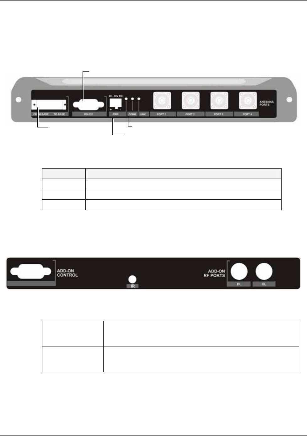
RU 2000 Rear Panel
The RU 2000 rear-panel provides the control, RF interface and optic interface ports that enable
connecting an MA 1200 add-on unit to the RU 2000 module.
Figure 2-10. RU 2000 Rear
Table
2-6. RU 2000 Rear Panel Connectors
Add-on control Transmits the control signals from MA 1200 add-on module to the
RU 2000 module. The Add-on Control port is connected to the MA
1200 add-on From port.
DL, UL Transmit the RF signals to- and from- the MA 1200 add-on module.
These ports are connected to the corresponding ports on the MA
1200 rear panel: DL to DL, UL to UL.
Fiber optic BU
connections Power connector
LEDs
MA service
onne to
RF ports 1 to 4
MA 2000 System Elements
MA Remote Location Elements
MA 2000 Installation and Configuration Guide 19
2.2.2 MA 1200 Add-on
The MobileAccess 1200 Add-on module is used to provide support for an additional service to an
MA 2000 RU. The host MA RU and the MA 1200 add-on are interconnected and either housed in
a MA 2000 Cabinet or connected externally to a MA 2000 Lite ‘enclosure’.
MA 1200 Add-on provides the following functions:
• Single service – either low-band or high-band
• Installed only as an addition to a MA 2000 RU
NOTE: The RU 2000 provides the interface to the optical, RF and control signals for both modules. In
addition, the RU 2000 performs the optical to RF (and vice versa) conversion for both modules.
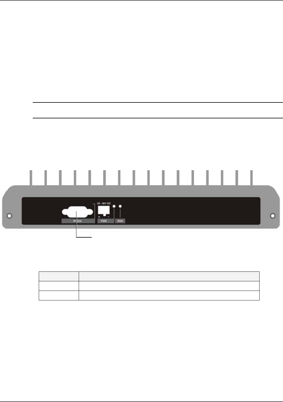
MA 1200 Front Panel
The RU 1200 front panel contains the power connection and status LEDs. (The RS-232 connector
is reserved for MA service personnel).
Figure 2-11. RU 1200 Front panels
Table
2-7. MobileAccess 1200 Front Panel Indicators
LED Description
RUN When blinking, indicates that the RU is in normal operating mode.
PWR Power ON
Service connector
MA 2000 System Elements
MA Remote Location Elements
MA 2000 Installation and Configuration Guide 20
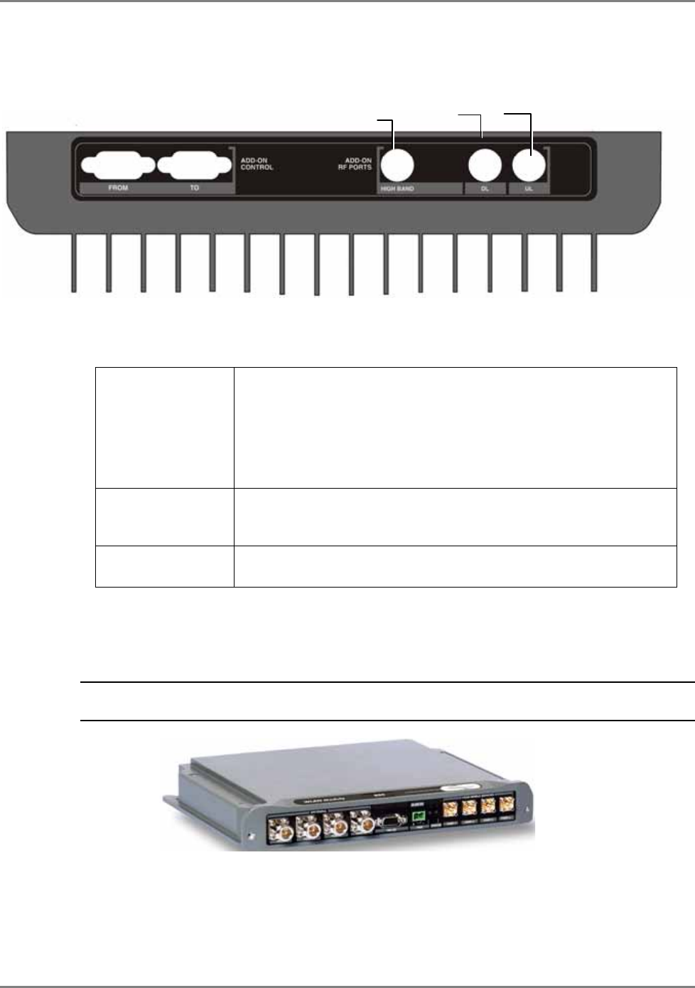
MA 1200 Rear Panel
The RU 1200 rear panel contains the control connectors and the RF connections to the RU 2000
and MA 850.
Figure 2-12. RU 1200 Rear Panel
Table
2-8. RU 1200 Rear Panel Connectors
Add-on Control Transmits the control signals between the MA 1200 module and the
MA 850 and RU 2000 modules.
From – receives control signals from the RU 2000. Connected to
the RU 2000 Add-on Control connector.
To – feeds control signals to MA 850 (in configurations that include
MA 850)
DL, UL Transmit the RF signals to- and from- the MA 1200 add-on module.
These ports are connected to the corresponding ports on the MA
2000 rear panel: DL to DL, UL to UL.
High Service RF output port. Connected to combiner/splitter to be
combined with other services supported by the MA 2000 system.
2.2.3 MA-850 Module
Note: This section provides a brief description of the MA 850 module. For a full description of the module,
refer to the MA 850 Installation and Configuration Guide
Figure 2-13. MA 850 Module
High Band DL UL
MA 2000 System Elements
MA Remote Location Elements
MA 2000 Installation and Configuration Guide 21
MobileAccess 850 provides a
secure
and
centralized
connection for 802.11a/b/g Access Points. It
significantly expands 802.11a/b/g coverage and enables distributing data and voice services over
the same coax and antenna infrastructure used by MA 2000 system.
MA 850 is installed externally to the MA 2000 Cabinet and the MA 2000 Lite ‘enclosure’.
MA 850 provides the following functions:
• Converges services from 802.11a/b/g APs
• Connects to the antenna ports of the MA 2000 Cabinet/Lite and interfaces to the antenna
infrastructure
• Local management through an RS232 connection and the MA 850 Management application
• Remote management monitoring through an Ethernet connection
The MA 850 front and rear panels, connectors and connections are described in detail in the
following sections.
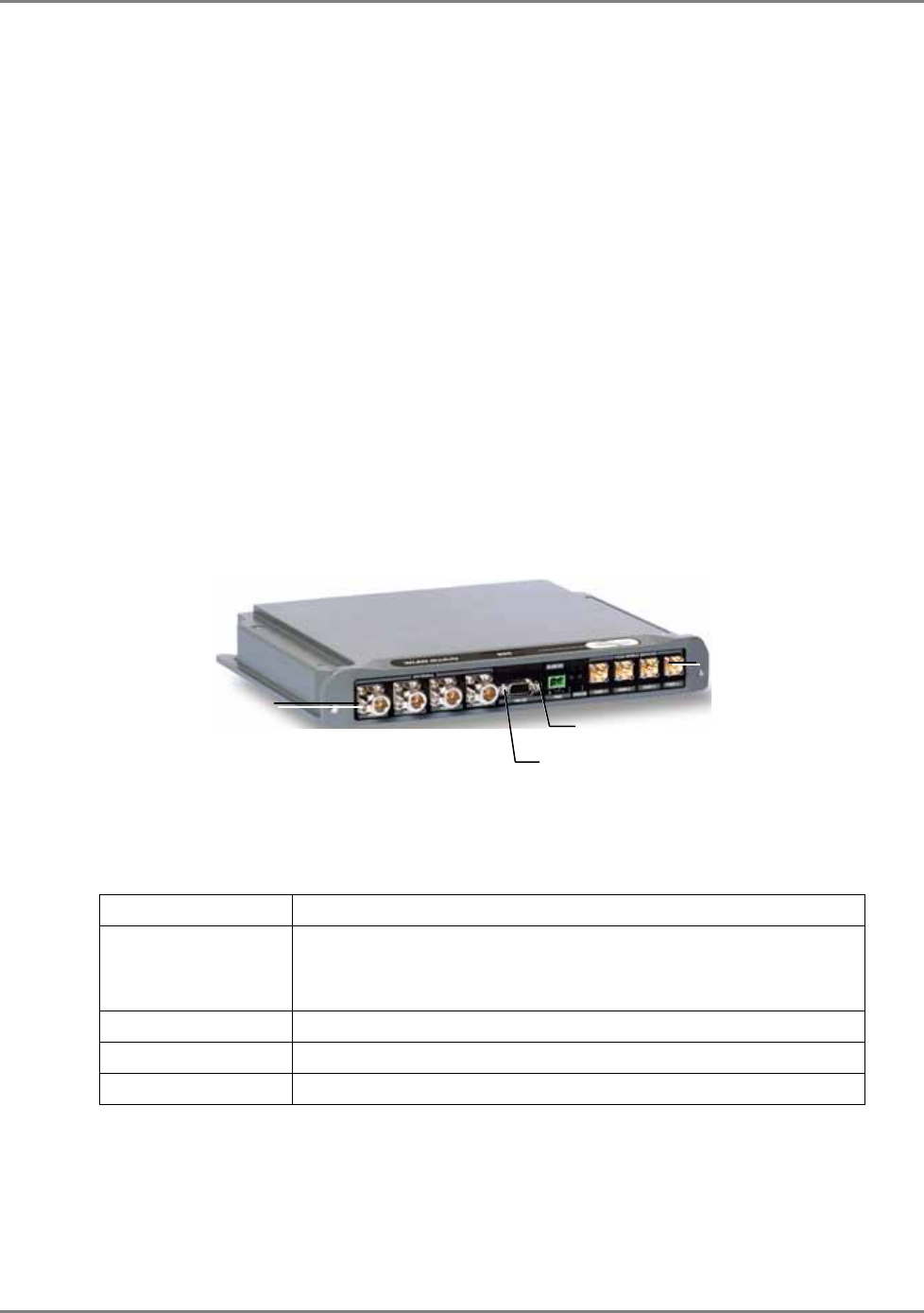
MA 850 Front Panel
The MA 850 front panel contains the antenna ports interfaces, local configuration interface and
power connection.
The following figure shows the MA 850 front panel.
Figure 2-14. MobileAccess 850 Front View
Table
2-9. MA 850 Front Panel Connections
Front Panel Description
Mobile Services Four SMA female connections to which the antenna port of the
MA 2000 system are connected.
To be terminated with 50 ohm terminations when not in use
Antenna Ports Four n-type female antenna connections
Local Local connection for setup
DC Power connection: 20V to 48V from a standard power supply
Antenna ports
Connections to
corres
p
ondin
g
antenna
Local RS232 connection
for configuration
Power
MA 2000 System Elements
MA Remote Location Elements
MA 2000 Installation and Configuration Guide 22
MA 850 Rear Panel
The MA 850 rear panel contains the connections to the APs, the Ethernet port for remote
configuration and the connection to the MA 1200 add-on control (if an MA 1200 add-on unit is
installed)
Figure 2-15. MobileAccess 850 Rear View
Table
2-10. MA 850 Rear Panel Connections
Rear Panel Description
802.11b,g APs Connection to up to four 802.11b/g APs, where associated LED
Lite under the following conditions:
o Green: indicates where AP should be connected after
configuration
o Green flickering: Link with AP established but no data is
received
o Red: AP transmitting data
802.11a APs Connection to up to four 802.11a APs
Connection to
control Connection to MA 2000 Chassis/Lite RS232 front panel antenna
sensor.
Ethernet port Connection to network for Web configuration
802.11 b/g APs
connections
Ethernet
Port
802.11 a APs
connections
Control connection to
MA 2000 antenna
MA 2000 System Elements
MA Remote Location Elements
MA 2000 Installation and Configuration Guide 23
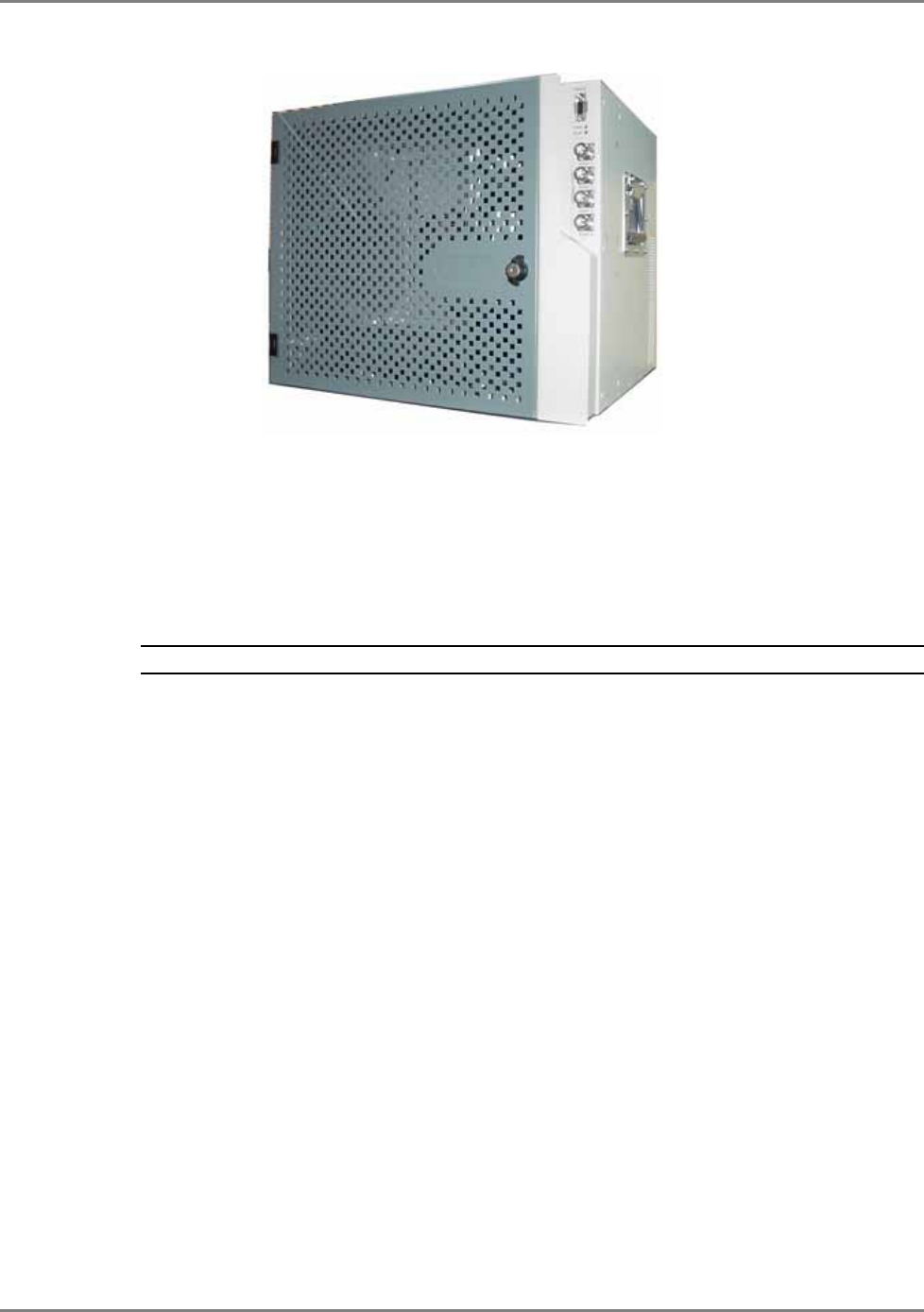
2.2.4 MA 2000 Remote Cabinet
Figure 2-16. RC 2000 Closed Cabinet View
The MA 2000 Remote Cabinet provides support for up to 20 multi-operator services through a
single coax antenna infrastructure.
MA 2000 Cabinet provides the following functions:
• Compactly houses up to a total of five RU 2000 and MA 1200 modules and the required
filters
NOTE: The number of modules depends on the models, required filtering, etc.
• MA 850 can be connected externally
• Converges all voice services and provides a single interface to the antennas through external
connections
• Wall mounted or rack mounted
• Two MA 2000 Remote cabinet models:
• Integrated power supply – fed from an external AC power source. The RU 2000 an MA
1200 Add-on modules are internally connected to the power supply. This model includes
a battery connection as well.
• External power supplies – power is routed to external connectors from which power is
routed internally to each RU 2000 and MA 1200 Add-on module.
MA 2000 System Elements
MA Remote Location Elements
MA 2000 Installation and Configuration Guide 24
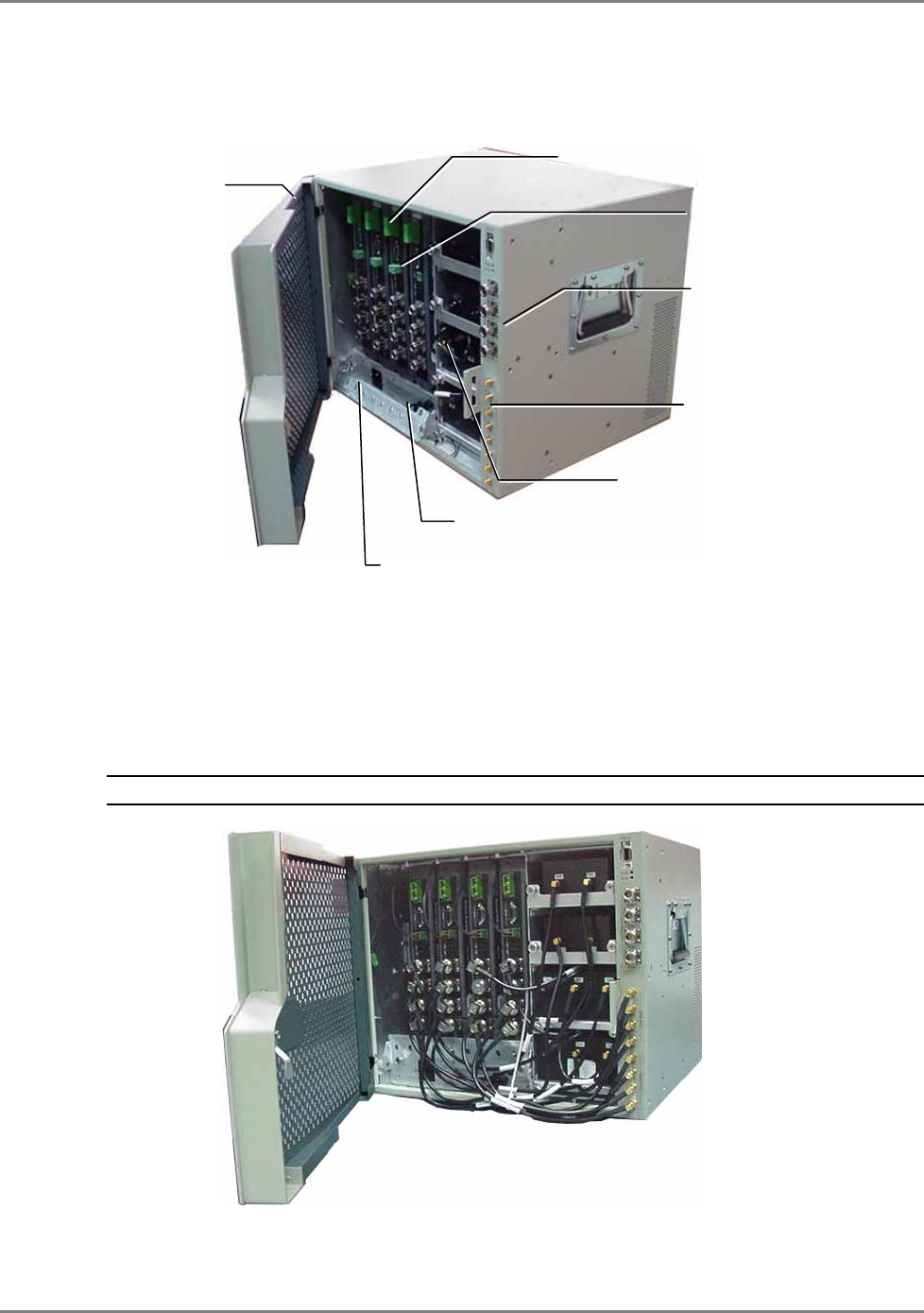
Open door views
The following figure shows an open RC 2000 cabinet, integrated power supply model, with four
RU 2000 modules and four filters. (For clarity, the internal connections are not included).
Figure 2-17. RC 2000 Open Cabinet View (without internal connections)
The following image shows the MA 2000 RC with the cabling. The antenna ports of the individual
modules are connected to the internal RF connections and to the relevant filters. The PS
connections of each module are also connected to cables that are internally routed to the
integrated PS.
NOTE: The fiber optic connections are not displayed.
Figure 2-18. RC Open Cabinet with Internal Cabling
Optic fiber connection from
the corresponding BU
Slot for fitting
Optic Fibers
AC power input to
integrated power supply
Internal DC module
connections
Splitter/Combiner
connections
Filters (four in this
configuration example)
Connection to
external battery
Antenna ports
MA 2000 System Elements
MA Remote Location Elements
MA 2000 Installation and Configuration Guide 25
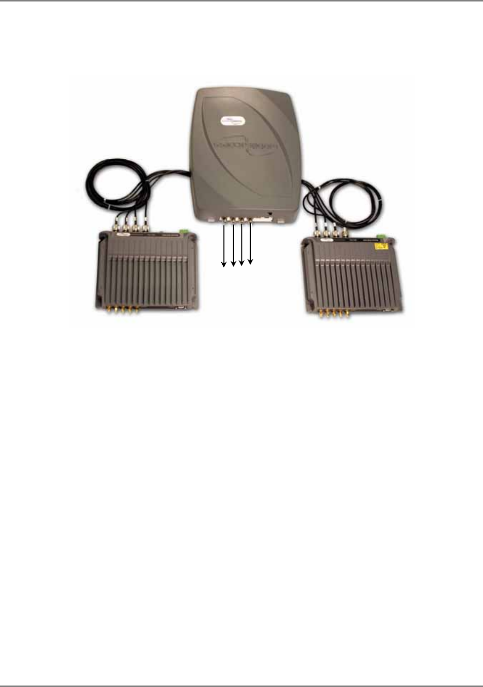
2.2.5 MA 2000 2000 Lite
Figure 2-19. 2000 Lite System
The 2000 Lite is designed to support up to 8 voice services, in addition to 802.11 data
services.
MA 2000 Lite capabilities:
• External connections to two MA 2000 RUs (to which MA 1200 Add-on units can be added)
• Filters and combiner (converges all services) are installed in the enclosure
• Connection to MA 850 for support of 802.11a/b/g data services
• External power supplies
MA 2000 Lite (filter and
combiner enclosure)
RU 2000
Antenna connections
RU 2000
MA 2000 System Elements
MA Remote Location Elements
MA 2000 Installation and Configuration Guide 26
2.2.6 8 x 4 Combiner
NOTE: This unit is internal to the MA 2000 system – both Cabinet and Lite models.
This unit is installed in the MA 2000 system Cabinet and MA 2000 Lite and Lite enclosures. The
8x4 Combiner unit combines the antenna interface ports the RUs and provides a common
interface to the coax antenna infrastructure.
The 8x4 Combiner provides the following capabilities:
• Supports up to eight inputs: four high-band and four low-band
• Provides low RF loss and high isolation for the input devices
• Antenna interface ports are located externally on the MA 2000 Cabinet and MA 2000
Lite.
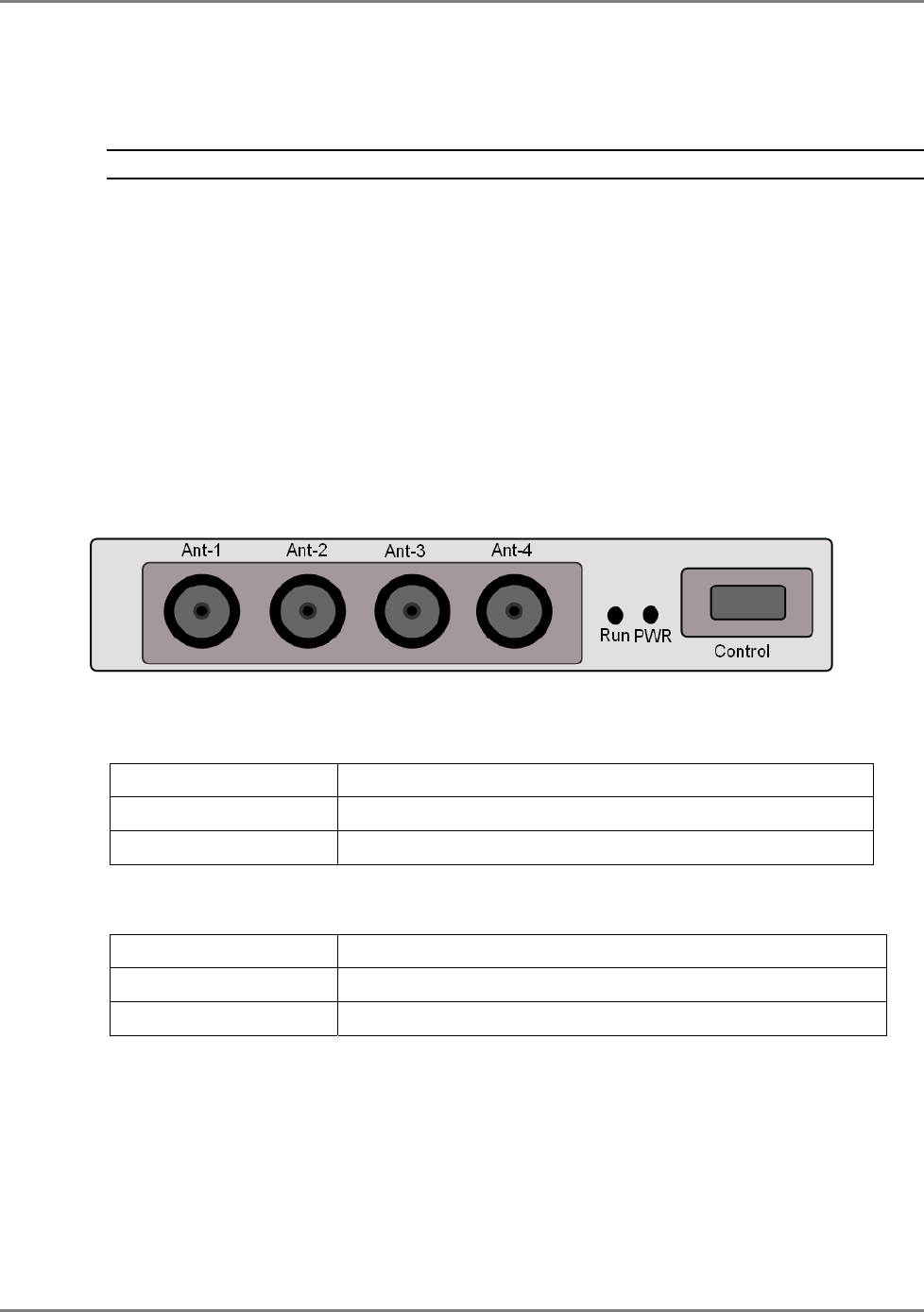
The front panel of the unit contains the four antenna interface ports, LEDs and control port.
Figure 2-20. 8x4 Combiner Front Panel
The following table describes the front panel connectors.
Connector Description
Ant-1 to Ant-4 (N-type) Coax connections to corresponding antennas
Control Relevant to Future Option
The following table describes the front panel LEDs.
Connector Description
Run Relevant to Future Option
Power Relevant to Future Option
MA 2000 System Elements
MA 2000 Remote Management Elements
MA 2000 Installation and Configuration Guide 27
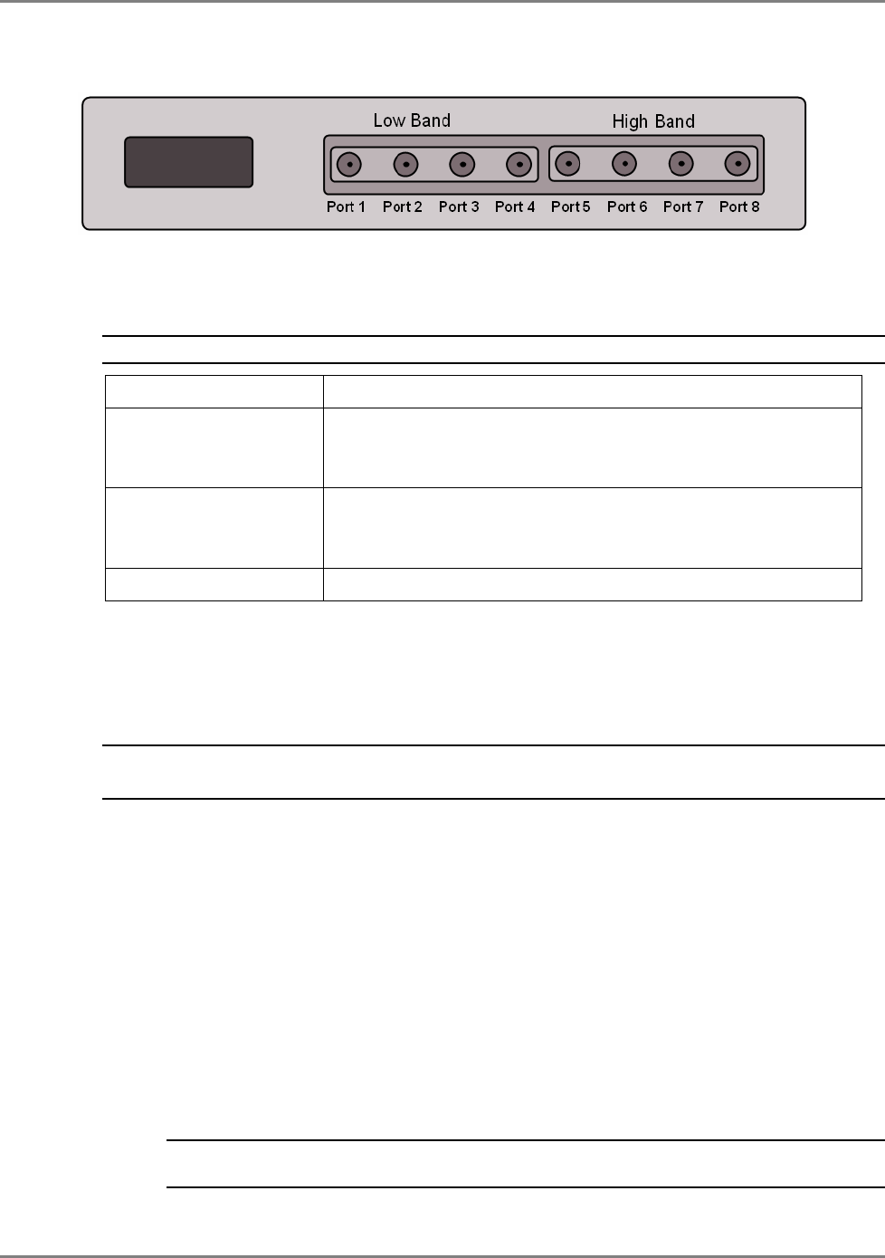
The rear panel of the unit contains four low-band and four high-band ports as well as the control
port.
Figure 2-21. 8x4 Combiner Rear Panel
The following table describes the rear panel connectors.
NOTE: Connector on rear panel is for future option.
SMA Connectors Description
Low Band Four connectors for the low-band outputs of the corresponding
remote unit. Refer to
Chapter
6
for the exact connections
relevant to each configuration.
High Band Four connectors for the high-band outputs of the
corresponding remote unit. Refer to
Chapter
6
for the exact
connections relevant to each configuration.
Control Interfaces to the Digital card (that enables antenna monitoring)
2.3 MA 2000 Remote Management Elements
NOTE: This section provides general information on the MobileAccess NMS. For detailed information on
the controller, configuration and connections refer to the Mobile Access NMS User
’
s Guide.
The system elements can then be monitored via a connection to the host controller. The type of
connection and monitoring depends on the type of controllers that are installed, the
configuration and the available management applications:
• MA 410/430 Controller – The controller provides the interface between the system
elements and the management and control mechanism. Two controller models are
available:
• MobileAccess 410™ – enables management of the connected devices through a local or
point-to-point dial-up connection. It can be remotely managed through a connection to
the MobileAccess 430 controller.
• MobileAccess 430™ – enables management of all connected elements and all connected
MA 410 controllers and the corresponding elements. Supports SNMP (Simple Network
Management Protocol) over TCP/IP connection.
NOTE: MA 430 may be managed through the Network Operator Center (NOC) through Manager
of Mangers element such as HP OpenView via SNMP.

MA 2000 System Elements
MA 2000 Remote Management Elements
MA 2000 Installation and Configuration Guide 28
• MCT – a Java based GUI application provided with both controllers. The MCT is used
after the installation procedure to adjust MobileAccess devices according to the
installation site characteristics in order to optimize coverage for the site.
The application is installed and ran from a computer that is connected either locally or via
remote dial-up modem to the controller site to be adjusted or monitored.
• MA NMS Manager™ – a Java based GUI software application that provides enhanced
monitoring and control capabilities for all your
MA 430™
sites from a single location;
each site can consist of a standalone MA 430 controller, or a MA 430 controller in a
Master topology with a number of MA 410 controllers connected as slaves.
The MA NMS application is installed on a server and is accessed from any client by
connecting to the server from any Web Browser with enhanced Java VM capabilities.
NOTE: The MobileAccess Manager application is not supplied with the controller – it is purchased
separately.
MA NMS manager provides the following features and capabilities:
• Remote SNMP management from a single location
• Client/server management capability over a TCP/IP network with enhanced monitoring
and control capabilities
• Intuitive GUI that enables end-to-end fault sourcing from RIU to antennas. The GUI
includes:
• System status at a glance through multi-color tree with upward propagation of fault
indications
• Graphical view of system elements including LED status displays and auxiliary
connections
• Multi-color event monitoring display RF Connections
MA 2000 System Elements
MA 2000 Remote Management Elements
MA 2000 Installation and Configuration Guide 29
2.3.1 MA 410/430 Controller
MobileAccess provides two controller models: MA 410 and MA 430. The controllers enable
monitoring all directly connected devices, such as BUs and RIUs, as well as all the RUs and
antennas corresponding to each BU. In addition, MA 410 and 430 controllers may be
interconnected in a Slave/Master configuration that can be monitored through a single
connection. MA 410/430 controllers differ in the type of connections they support.
The controllers provide the following functions:
• Interface to up to eight BUs, where two of the BU ports can be used for connecting RIUs (six
BUs and two RIUs)
• Front panel LCD display – provide status information on local and remote connections
• Auxiliary alarms – for connections to external devices
• Dry-contact alarms – for connections to BTS/BDA
• MA 410 – monitoring through RS232 and dial-up connection
• MA 430 – monitoring through SNMP (Simple Network Management Protocol) over TCP/IP
connection (as well as RS232 and dial-up)
• Master/Slave connection for monitoring multi-controllers through a single connection - MA
410 controllers connected to MA 430 controllers as slaves
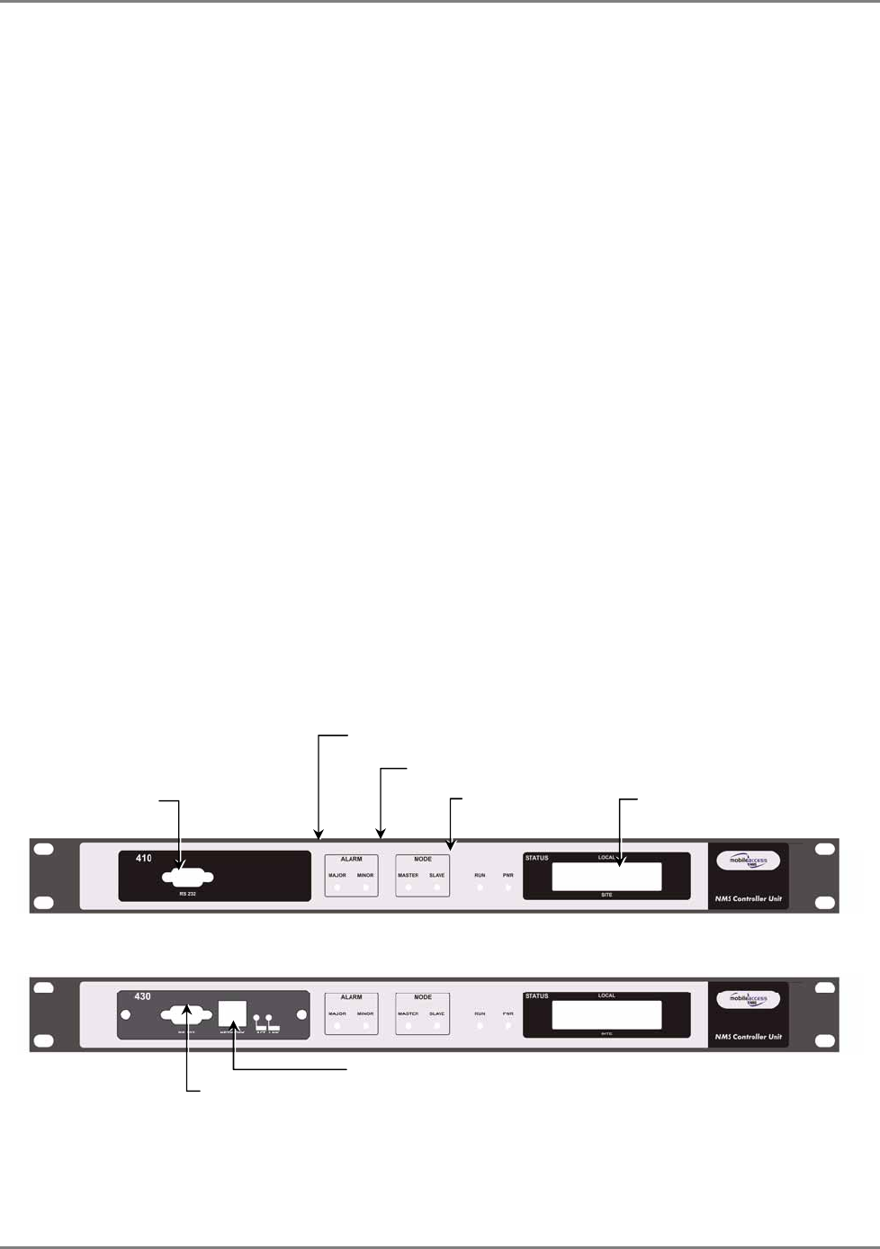
2.3.1.1 MA 410/430 Controller Front Panel
This section describes the front panels of MA 410 an MA 430 controllers. Note that the only
difference is in the connection type; all indicators (LED and LCD display) are the same.
Figure 2-22. MobileAccess 410 Front Panel
Figure 2-23. MobileAccess 430 Front Panel
Local RS232
connection
LCD alarm display
corresponding to Major
and Minor LEDs
Major, Minor LED
indicators
Master/Slave configuration
Run and
Power LEDs
T
CP/IP connection
Local RS232 connection

MA 2000 System Elements
MA 2000 Remote Management Elements
MA 2000 Installation and Configuration Guide 30
Table
2. MA 410/430 Front Panel Connectors
Connector Description
RS232
Connector Used for setup and RS232 monitoring.
For MA 430 front panel, this connector is used for setting up the network
parameters (IP Address, community names, etc.).
Network MA 430 only - Ethernet TCP/IP connection to network.
Table
2. MA 410/430 LED Indicators
LED Description
Network
connection.
For MA 430 only
Active LED – Blinks during TCP/IP communication.
Link LED - ON as long as a TCP/IP network connection exists.
PWR ON green - indicates correct power level
Run ON green - flickers continuously indicating the controller is initialized and
running.
Mode Controller Master or Slave mode.
Master green – lit if the controller is installed as a ‘stand-alone’ or is
configured as a Master.
Slave green – lit if the controller is configured as a Slave.
Failure Indicates whether the alarm is ‘Major’ or ‘Minor’ type of alarms:
Minor red – indicates a single faulty RHU in a building with more than one
RHU
Major red – indicates faulty RHU in a single RHU site, more than one faulty
RHU in a site with multiple RHUs, fault on any of the auxiliary inputs, or
other faults.
MA 2000 System Elements
MA 2000 Remote Management Elements
MA 2000 Installation and Configuration Guide 31
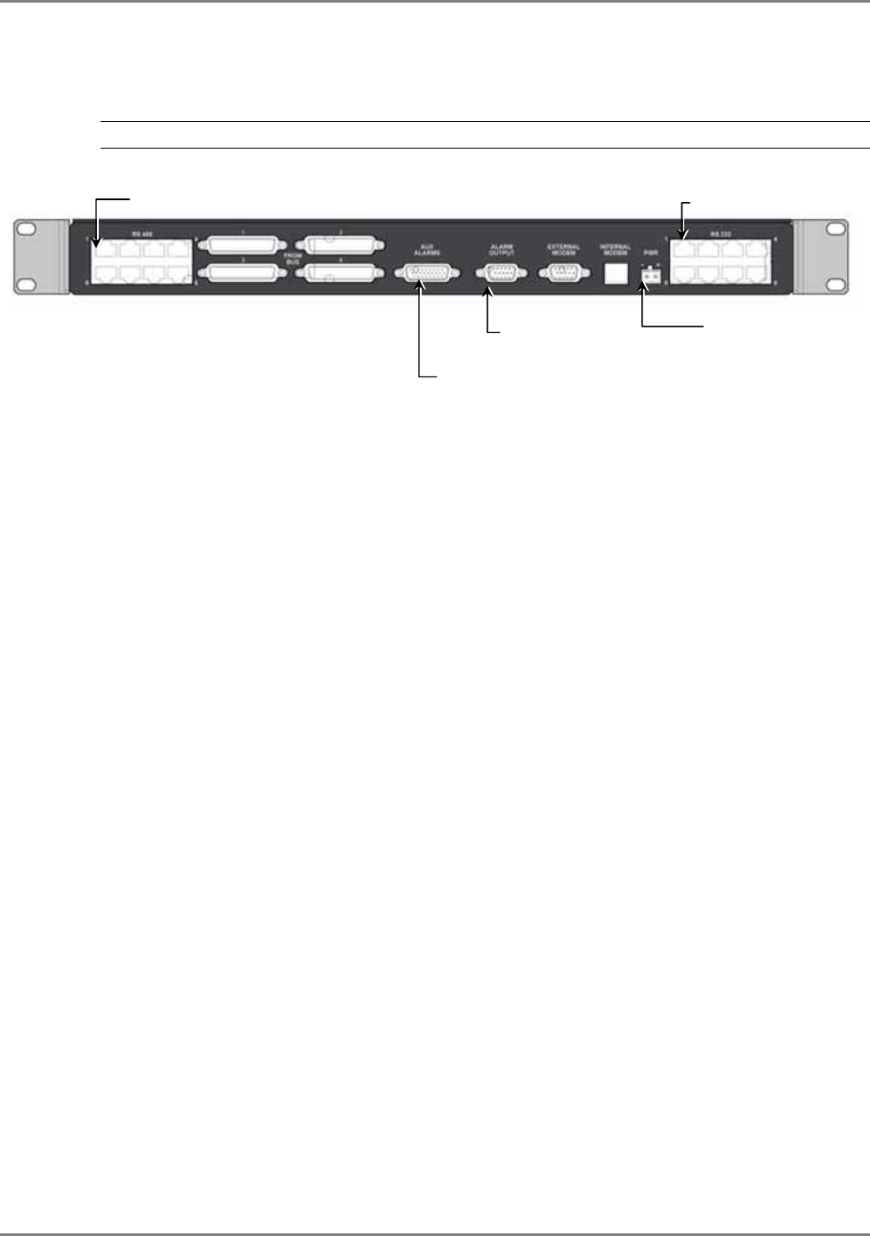
2.3.1.2 MA 410/430 Controller Rear Panel
Note: The rear panels for the MobileAccess 410 and MobileAccess 430 are the same.
Figure 2-24. MobileAccess 410/430 Rear Panel
DC In
p
ut
General purpose
alarms.
BTS/BDA alarms
output
MA BU and RIU
connections Slave controller
connections

MA 2000 System Elements
MA 2000 Remote Management Elements
MA 2000 Installation and Configuration Guide 32
Table
2. MA 410/430 Rear Panel Connectors
Connector Description
RS485 MobileAccess Base Units and RIU connections. NMS-RJ45 cables.
Connection limitations:
o Up to eight MA BUs on any of the ports
o Up to two RIUs connected only to ports 1 and 5
From BU Four Legacy BU connections using NMS-BU/DB25 cables.
RS232 MA 430 only. Eight connections to Slave controllers.
Auxiliary Alarms Eight inputs for alarms from auxiliary devices
Alarm Output BTS/repeater dry-contact alarms. NMS-BTS/DB15-open cables.
External Modem Future option. Connection to an external wireless or dial-up modem.
Internal Modem Used for dial-up connection to the controller – MCT setup and monitoring
PWR DC power input: 20 to 48VDC, 0.5A max
2.3.2 MCT
MCT – a Java based GUI application provided with both controllers. The MCT is used after the
installation procedure to adjust MobileAccess devices according to the installation site
characteristics in order to optimize coverage for the site.
The application is installed and ran from a computer that is connected either locally or via
remote dial-up modem to the controller site to be adjusted or monitored.

MA 2000 Installation and Configuration Guide 33
3
S
Si
it
te
e
P
Pr
re
ep
pa
ar
ra
at
ti
io
on
n
3.1 Infrastructure Preparation
This following installation rules are based on the assumption that site survey and installation
planning (
including power requirements
) have been completed. Installation Requirements
3.2 Installation Requirements
The infrastructure preparation consists of two main phases:
A. Floor Planning: Planning the distribution of the antennas on each floor to provide the
required coverage.
B. Telecom Closet Planning: Planning the layout of the devices and cables in the telecom
closet or shaft. This includes the MA 850, 802.11 Access Points, cabling and other voice
service distribution systems that are relevant to the specific installation.

Site Preparation
Coaxial Cable Connections
MA 2000 Installation and Configuration Guide 34
3.3 Coaxial Cable Connections
3.3.1 General Cable Installation Procedures
Observe the general cable installation procedures that meet with the building codes in your area.
The building code requires that all cabling be installed above ceiling level (where applicable).
Each length of cable from the risers to each antenna must be concealed above ceiling.
The cable must be properly supported and maintained straight using tie-wraps, cable trays and
clamps or hangers every 10 feet (where practical above ceiling level). Where this is not practical,
the following should be observed:
• The minimum bending radius of the supplied ½” coax cable should be 7”.
• Cable that is kinked or has a bending radius smaller than 7” must be replaced.
• Cable runs that span less than two floors should be secured to suitably located
mechanical structures.
• The cables should be supported only from the building structure.
3.3.2 Fiber Optic Rules
• Use only single mode fiber for indoor applications.
• Use only 8-degree SC/APC connectors (green color).
• Use only fusion splice for connecting two fibers.
• Use minimum splicing/connectors to achieve minimum losses on the fibers (<0.5dB).
• Use precaution while installing, bending, or connecting fiber optic cables.
• Use an optical power meter and OTDR for checking the fiber optic cables.
• Make sure the environment is clean while connecting/splicing fiber optic cables.
• All fiber optic connections should be cleaned prior to attaching to termination points
using a dry cleaning device (i.e. Cletop or equivalent).
• Fiber connector protective caps should be installed on all non-terminated fibers and
removed just before they are terminated.
• Verify the Fiber Optic connections. You may use the Optical Test Procedure described at
the end of this manual.
• Pay special attention while connecting the SC/APC connectors - you must hear the “click”
when the connection is made.

Site Preparation
Coaxial Cable Connections
MA 2000 Installation and Configuration Guide 35
3.3.3 RF Rules
• Use coax RG223, 50ohm, male-to-male N-type for RF connections from the BUs to the
BTS/RBS and to the RIU.
• When using the MobileAccess™ system in an environment in which other indoor
coverage systems are installed, it is recommended (where possible) that the antennas
are placed at least two meters apart
• When bending coax cables, verify that the bending radius does not exceed the coax
specifications.
• Use wideband antennas supporting a range of 800Mhz to 2500Mhz
• Use a VSWR meter (i.e. Site Master or equivalent) for checking coax cables, including
the antennas. (<2). The VSWR must be measured prior to terminating the RUs in the
remote communication rooms
• Terminate all unused RU and RIU ports with a 50 ohm load
3.3.4 Coax Cable Lengths and Losses
Use coax ½”, 50ohm, male-to-male N-type, for connecting to RHU and antenna ports.
NOTE: The required distance between the antennas (installed in the ceiling) depends on the infrastructure
and calculated path-loss. For example, if there is free space-loss between the antennas, a minimum
distance of 100 ft is required; if there are partitions (loss) between the antennas, a distance of less than
100 ft between them is allowed.
Coax Length coax Loss (900Mhz) connector loss Total Loss
30 0.7 1.5 2.2
40 0.9 1.5 2.4
50 1.1 1.5 2.6
60 1.3 1.5 2.8
70 1.5 1.5 3
80 1.7 1.5 3.2
90 1.9 1.5 3.4
100 2.1 1.5 3.6
110 2.3 1.5 3.8
120 2.5 1.5 4
130 2.7 1.5 4.2
140 2.9 1.5 4.4
150 3.1 1.5 4.6
160 3.3 1.5 4.8
170 3.5 1.5 5
180 3.7 1.5 5.2
190 3.9 1.5 5.4
200 4.1 1.5 5.6
Site Preparation
Power Consumption, Connections and Power Supplies
MA 2000 Installation and Configuration Guide 36
3.4 Power Consumption, Connections and Power
Supplies
3.4.1 Power Safety Instructions
SAFETY WARNINGS
• When installing or selecting the power supplies:
• Be sure to disconnect all power sources before servicing.
• MA 410/430 Controller lithium type battery should only be replaced by MobileAccess
service personnel. Risk of exploding if battery is replaced by an incorrect type.
Dispose of used batteries according to the instructions.
• Calculate the required power according to the requirements of the specific installation
and then determine the configuration of the power supplies. The required DC cables will
then be determined by the selected PS configuration.
• Use only UL approved power supplies
• AC and DC power supply cables – use only the power cords supplied with the units
• Battery replacement in units - only the MA 410/430 controller has batteries. These
should be replaced (when necessary) only by MA Service Personnel.
• Install external over-current protective devices for the system according to the
requirements described in section 3.4.3.
3.4.2 Power Consumption of Units
Table
3-1. MobileAccess™ Power Requirements
Unit Type Voltage Input Typical Power
Consumption Maximum Current
Consumption
2000 Remote Cabinet 20 to 48VDC 25W 1.25A
2000 Lite 20 to 48VDC 4W 0.2A
RU 2000 20 to 48VDC 25W 1.25A
Add-on Unit 1200 25 to 48VDC 50W 2.0A
RIU 20 to 48VDC 12W 0.6A
Base Unit 20 to 48VDC 14W 0.7A
410/430 Controller 20 to 48VDC 10W 0.5A
MA 850 20 to 48VDC 20W 1.0A
3.4.3 Circuit Breakers
Install fuse protections for the system according to the following criteria:

Site Preparation
Power Consumption, Connections and Power Supplies
MA 2000 Installation and Configuration Guide 37
• The following system elements require external fuse protection: RIUs, BUs, and
410/430 Controllers.
• Referring to Table 3-1, calculate the required fuse protection.
• Example: a set of three elements consisting of a BU, RIU and MA 410/430 controller
requires a 2A circuit breaker.

Site Preparation
Installation Conventions
MA 2000 Installation and Configuration Guide 38
3.4.4 Types of Power Supplies
MobileAccess supplies various power supplies that can be installed in a rack or mounted on a
wall, depending on your configuration.
Table
3-2: MobileAccess™ Power Supplies
Power Supply
LPS-48V-66W Local AC/DC Converter 40W
LPS-48V-100W Local AC/DC Converter 100W
RPS-200-N-48 Non-redundant 200W 110/220V Wall Mount.
Not to be used in North America
RPS-500-R-48 Redundant 500W 110/220V Chassis Mount.
Not to be used in North America.
RPS-1000-R-48 Redundant 1000W 110/220V Chassis Mount
RPS-14-50W-48 Remote power supply,14 modules of 50W,48V
RPS-14-100W-48 Remote power supply,14 modules of 100W,48V
RPS-6M-220 Remote power supply enclosure,6 Modules,220v in-48VDC.
Not to be used in North America
RPS-600W-220 Remote power supply module 600W/48VDC,220V in
Not to be used in North America
RPS-1200W-220 Remote power supply module 1200W/48VDC,220V in
Not to be used in North America
3.5 Installation Conventions
Some of the basic installation conventions are listed below for the MA 2000 system:
• Base Units – are usually concentrated in the same location, most often in the main
communication room.
• Remote Cabinet (or 2000 Lite) – usually placed in the communication shaft or closet
of a corresponding floor so they can be easily located. Each cabinet (or 2000 Lite) can
typically cover a floor of up to 30,000 sq ft.
• Fiber optic cable - bundled fibers are terminated into the Base Units in the main
communication room. The fibers are then routed to each coverage locations where
individual fibers terminate into splice boxes. The splice box couples the installed fiber
into the remote units. Enough spare fibers should be installed to take into account
future expansion of the system.
For example, for three remote units, six fibers are required. However, to allow for future
upgrades, it is recommended to install additional optic fibers to be connected to additional
RUs.
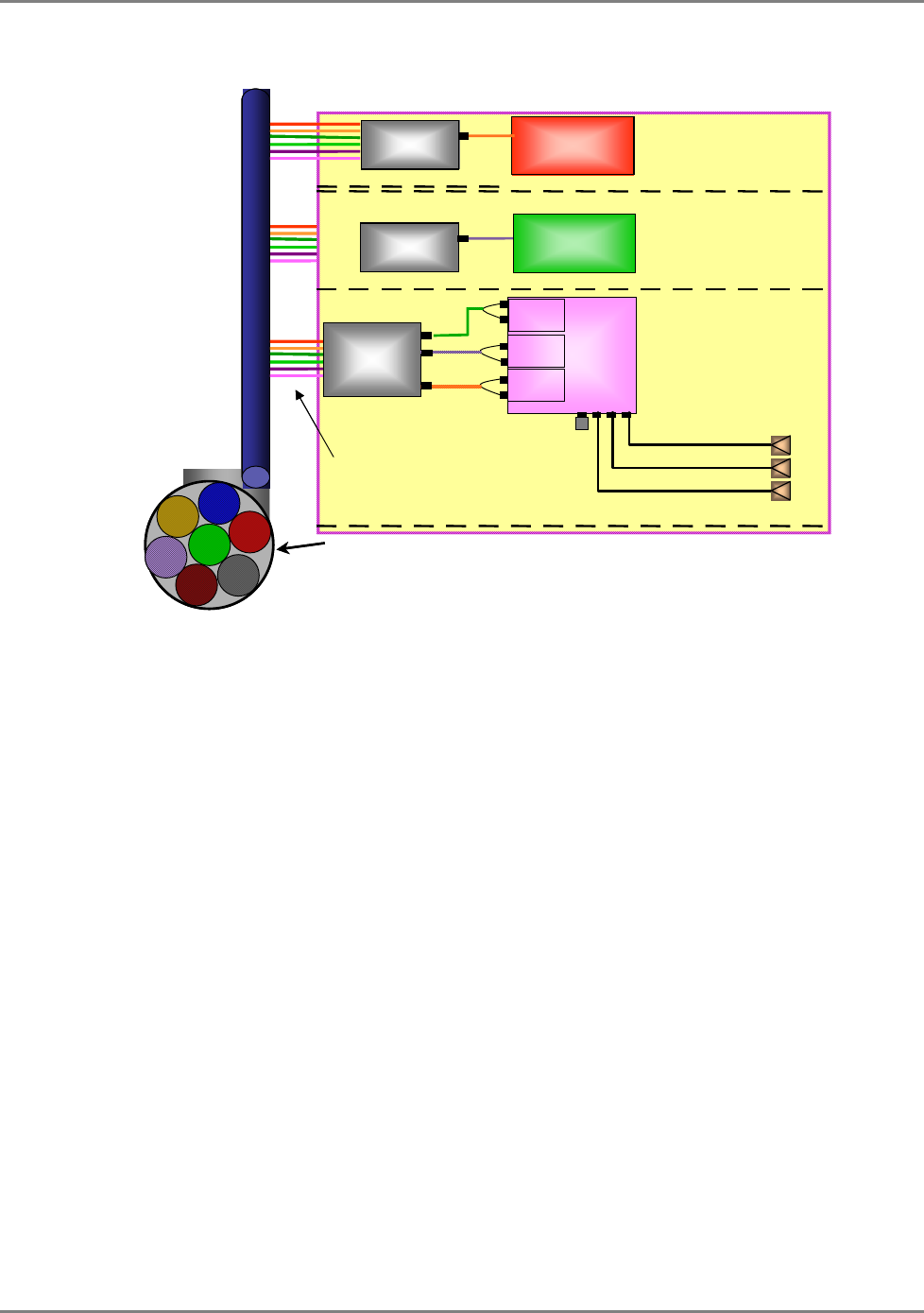
Site Preparation
Installation Conventions
MA 2000 Installation and Configuration Guide 39
The following figure illustrates fiber optic routing to Remote Cabinets.
Optical Cable
RC
Port 1
Port 2
Port 3
Ant.
1
Ant.
2
Ant.
3
Load
50 ohms
RC
RC
Floor 3
Floor 2
Floor 1
Fiber Optic Cables
8-Strand Fiber Cable
Assembly
(2 spare for
additional RUs)
Splice Box
Port 4
Splice Box
Splice Box
Fiber opt. In
Fiber opt out
Fiber opt. In
Fiber opt out
Fiber opt. In
Fiber opt out
Optical CableOptical Cable
RC
Port 1
Port 2
Port 3
Ant.
1
Ant.
2
Ant.
3
Load
50 ohms
RC
RC
Floor 3
Floor 2
Floor 1
Fiber Optic Cables
8-Strand Fiber Cable
Assembly
(2 spare for
additional RUs)
Splice BoxSplice Box
Port 4
Splice BoxSplice Box
Splice BoxSplice Box
Fiber opt. In
Fiber opt out
Fiber opt. In
Fiber opt out
Fiber opt. In
Fiber opt out
Figure 3-1. Illustration of Fiber Optic Routing
• For remote power supply configuration - cable bundles are routed from the main
communication room and individual wire pairs are terminated into the power feed of
individual units.
By providing power from a single distribution point, maintenance can be reduced and UPS
backup can be easily provided. The maximum distance from the source to the termination
spot is 1000 feet using 18 gauge wires.
In many locations local codes do not require power to be run through conduit if 100 watts or
less is used. Please consult the regulations in your local jurisdiction prior to deploying
remote power. When power cables require distances greater than 1000 feet 14 or 16 gauge
wire may be used.
• On each floor - the antennas are connected to the Remote Cabinet or 2000 Lite system
using coax cables.

MA 2000 Installation and Configuration Guide 40
4
S
Sy
ys
st
te
em
m
I
In
ns
st
ta
al
ll
la
at
ti
io
on
n
This chapter describes how the communication room and cabinet are installed. The individual
system elements and connections are described in the Chapter 2.
NOTE: Be sure to read the installation requirements (see
3.2) and Power Consumption related instructions
(see
3.3.4) before proceeding with the actual connections.
4.1 Pre-installation Instructions
In order to describe the installation process clearly, it will be described as consisting of two
logical parts:
A. Telecommunications room – installing the RIUs, BUs, MA 410/430
controllers, and the required
passive equipment
in the telecommunication room
close to the RF signal source. This installation may differ between single and multi-
building topologies.
B. Remote locations – two types of installations:
• MA 2000 Lite
• RC Cabinet
The installations for two basic topologies are described in detail: for single building and for multi-
building. By understanding the two generic installations you will be able to address any
variations in system deployment.
NOTE: For installations that include the MA NMS: Once the installation has been completed, it can be
verified using the MCT application (NMS User’s Guide) and the devices monitored using the NMS
Manager (NMS User’s Guide).

System Installation
Communication Room Installation
MA 2000 Installation and Configuration Guide 41
4.1.1 Unpacking and Inspection
This section provides instructions for opening the shipping boxes, verifying that all parts have
been received, and verifying that no shipping damage has occurred.
Unpack and inspect the cartons according to the following procedure
1. Open the shipping carton and carefully unpack each unit from the protective packing
material.
2. Check for signs of external damage. If there is any damage, call your MobileAccess service
representative.
4.2 Communication Room Installation
The Communication Room installation consists of the following basic steps:
1. Unpacking and inspecting the MA 2000 units (see 4.1.1)
2. Mounting the RIUs, BUs and 410/430 controllers in the mounting rack (see 4.2)
3 RF connections BTS/BDA connections.
4. RF connections to the Base Units.
5. Connecting the MA 410/430 control connections to the units
6. Connecting DC power to the units
4.2.1 Rack Installation General Instructions
NOTE: Usually, each operator installs the equipment that supports their services in a separate rack.
It is recommended to install the following MobileAccess system modules in a 19” rack in the
communication room
• RIU Chassis 3U, RIU Lite 2U
• BU 1U
• MobileAccess 410/430 controller 1U
• Fiber Optic patch panel and splice tray
• Power supply/supplies (MobileAccess – 3U for each unit; units from other manufacturers
may vary in size)
Verify that the rack height can support all the units to be installed, where you may also want to
consider future expansions.
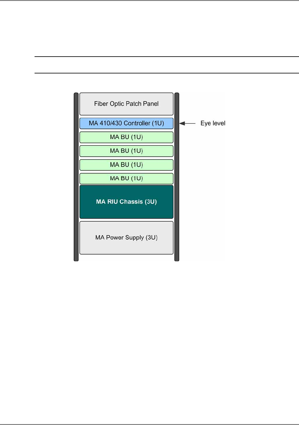
System Installation
Communication Room Installation
MA 2000 Installation and Configuration Guide 42
Figure 4-1 shows the recommended physical location of the MobileAccess elements in the rack in
order to facilitate and simplify the cabling
connections.
The configuration is for a single
operator. If the site is serviced by more than one operator, each operator often installs their
equipment in a separate rack.
NOTE: Note that the MobileAccess 430 controller is at eye level to provide an easy view of the LED
indicators and LCD display and easy access to the local and remote monitoring connections.
The following figure shows a typical installation for a two field design.
Figure 4-1: Recommended Order in the Communication Room Rack
4.2.2 Rack Installation Safety Instructions
Review the following guidelines to help ensure your safety and protect the equipment from
damage during the installation.
• Only trained and qualified personnel should be allowed to install or replace this
equipment.
• Verify that ambient temperature of the environment does not exceed 50°C (122°F)
• To maintain a low center of gravity, ensure that heavier equipment is installed near the
bottom of the rack and load the rack from the bottom to the top.
• Ensure that adequate airflow and ventilation within the rack and around the installed
components so that the safety of the equipment is not compromised. It is recommended
to allow for at least about 2 cm of airspace between devices in the rack.
• Verify that the equipment is grounded as required – especially the supply connections.
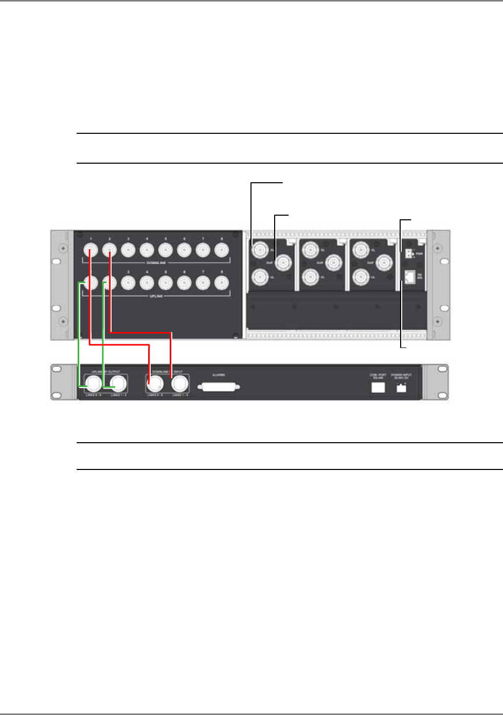
System Installation
Communication Room Installation
MA 2000 Installation and Configuration Guide 43
4.2.3 RIU (Chassis) Connections
4.2.3.1 RIU Connections
1. RIU to BU connections: connect each BU to the corresponding RF Uplink and Downlink
connectors on the RIU
rear panel
. For connections to more than four 8-port BUs, refer to
section 4.2.3.2.
NOTE: Each pair of uplink and one downlink RIU rear-panel ports are used to connect one OPTM. See
section 2.1.2. Two pairs are used to connect an 8-port BU (two OPTMs)
Figure 4-2. RIU Rear Panel showing the RF Connection
NOTE: Up to four 8-port BU may be connected. Additional BUs may be connected through the
Extension connector on the front panel. Refer to Connecting to Additional BUs, page 44.
2. BTS/BDA connections: Connect each BTS/BDA to the corresponding rear panel BTSC/BDAC)
connectors (BTSC and BDAC are service specific).
Both simplex and duplex connections are available for each connection:
• For a duplex connection, connect to the BTSC DUP port;
• For a simplex connection, connect to the BTSC UL and DL ports;
3. MA 410/430 controller connection: connect the RS485 port on the RIU rear panel to the MA
410/430 rear panel RS232 connector: port-1 or port-5.
4. Connect the Power connections to the RIU rear panel PWR port.
MobileAccess 1000 BU
connections (pair per BU) Power
Controller connection
BTS/BDA duplex
connections
BTS/BDA simplex
connections
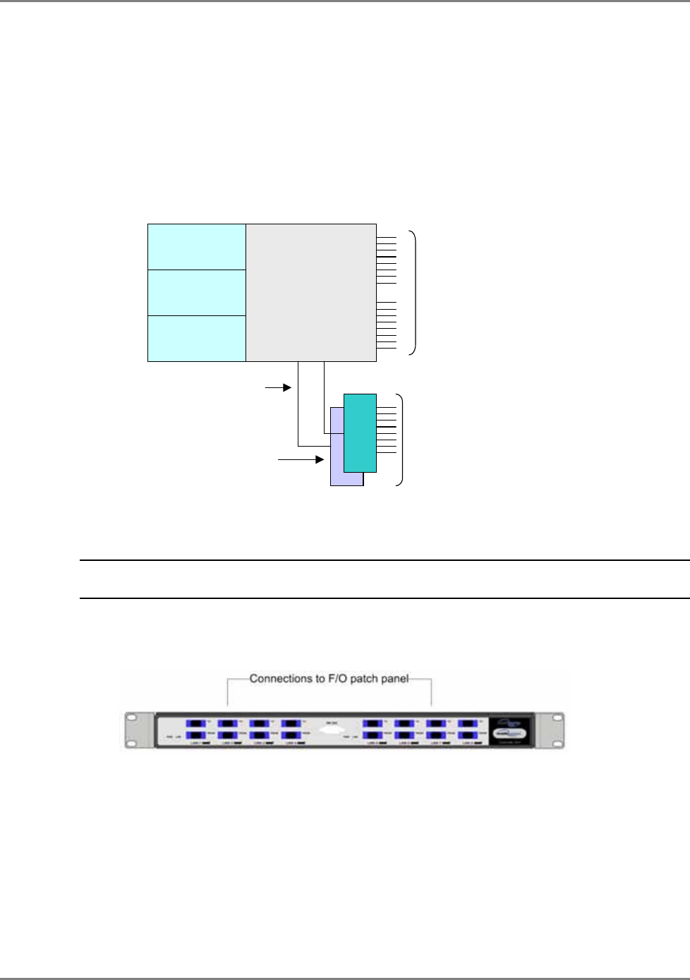
System Installation
Communication Room Installation
MA 2000 Installation and Configuration Guide 44
4.2.3.2 Connections to Additional BUs
To connect more than four 8-port BUs or more than eight 4-port BUs to the RIU:
• Connect an 8W splitter to the Downlink connector on the RIU front panel.
• Connect an 8W combiner to the Uplink connector on the RIU front panel.
• Connect additional BUs to the uplink and downlink connections.
Expansion ports
BTSCBTSC
BTSCBTSC
BTSCBTSC
Combiners
/Splitters
Compartment*
UL and DL
connections to
four BU8 modules
UL and DL connections
to up to four additional
BU8 modules
External 1:8 splitter
/combiner
4.2.4 BU Connections
NOTE: It is assumed that the patch panel cabinet (SC/APC adaptors) for fiber optic cable connections is
installed in the rack near the BUs.
1. Connect fiber jumper between splice tray and patch panel cabinet.
2. Connect fiber jumpers between the corresponding BU optical ports and the patch panel.
Figure 4-3. BU Front Panel Connections
3. Connect the BU rear panel Uplink and Downlink ports to the corresponding ports on the
RIU rear panel.
The following figure shows the BU connections to an RIU Chassis and MA 410/430 controller.
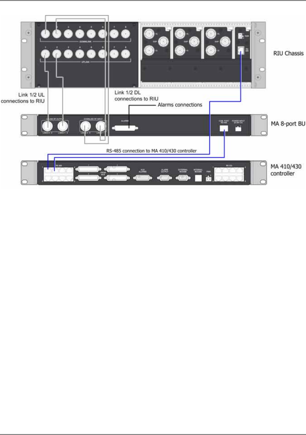
System Installation
Communication Room Installation
MA 2000 Installation and Configuration Guide 45
Figure 4-4. BU Rear Panel Connections
4. Connect the BU rear panel COM to the MA 430 rear panel RS485 connector.
5. Connect the Power connection on the BU rear panel.
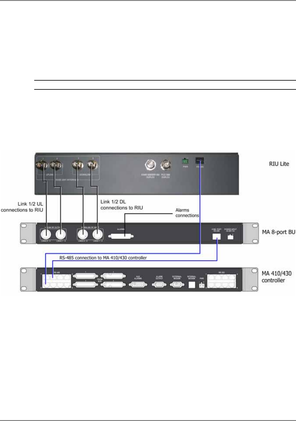
System Installation
Communication Room Installation
MA 2000 Installation and Configuration Guide 46
4.2.5 BU and RIU Lite Connections
1.
Connect the BU to the corresponding RF Uplink and Downlink connectors on the RIU Lite rear
panel. Note that one uplink and one downlink RIU rear-panel ports are used to connect one
OPTM (four ports from the BU).
NOTE: Only a single four 4-port BU may be connected.
2.
Connect each BDA to the corresponding rear panel Duplex connectors.
3.
Connect the Power connections on the RIU rear panel.
4.
If your system includes a MA 410/430 controller, connect the RS485 port on the RIU rear
panel to the controller rear panel RS485 ports (either Port-1 or Port-5).
Figure 4. MobileAccess RIU Lite-Controller connection

System Installation
Remote Cabinet Installation
MA 2000 Installation and Configuration Guide 47
4.3 Remote Cabinet Installation
Mount and install the Remote Cabinet (RC) in one of the following configurations:
• Wallmount - on the wall in the communication room
• Rackmount – in a 19” rack in the
communication room
allocated to that area (sometimes
referred to as a secondary communication room).
The procedure varies slightly according to the MA 2000 Cabinet mocel:
• Integrate power supply
• External power supply
The following sections describe both procedures.
NOTE: For installations that include MA 850 units, refer to the MA 850 Installation and Configuration Guide
for instructions on various installation options with the MA 2000.
4.3.1 RC 2000 Wall Mount Installation
General Installation Instructions
• The MA 2000 Remote Cabinet units should be installed in a communication room that
provides access to authorized personnel only. The units are maintenance free. In the
event of failure, only authorized personnel should handle the units.
• Environmental Data - Maximum ambient operating temperature: 45° C
Maximum ambient temperature in a rack: 45° C
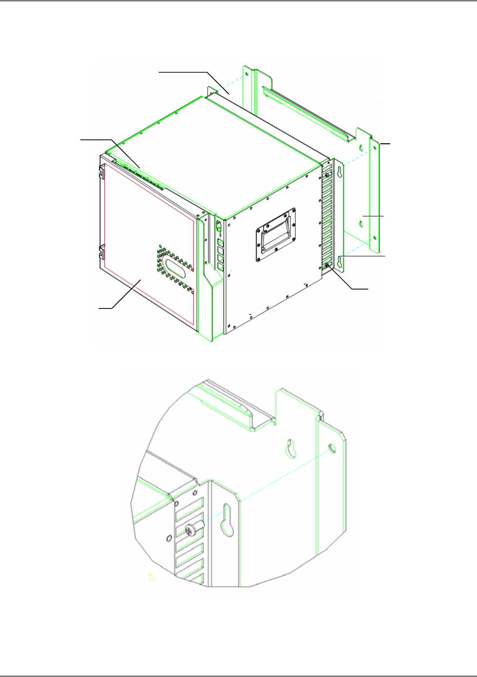
System Installation
Remote Cabinet Installation
MA 2000 Installation and Configuration Guide 48
The wall installation 2000 Remote Cabinet is supplied with a plate that is to be mounted on the
wall and a bracket that is assembled on the rear of the MA 2000 system.
Figure 4-5. MA 2000 System Wall Mount
Figure 4-6. Zoom of Mounting Holes
Plate to be
mounted on the wall
Mounting Bracket
Location of anchors
Opening through
which connected optic
fibers are routed
Underside opening
through which power
connections are routed
Rear panel
bracket
Holes for plate to
bracket assembly

System Installation
Remote Cabinet Installation
MA 2000 Installation and Configuration Guide 49
Mount the RC on the wall as follows:
ATTENTION: The following instructions apply to an installation on a
concrete wall. For any other type of wall, contact MobileAccess.
NOTE: For installations that include an MA 850 system, refer to the MobileAccess 850 Installation and
Configuration Guide.
1. For integrated power supply configurations only (for other configuration grounding is
optional), connect the cabinet GND according to section 4.3.2.
2. Using the plate as a guide, drill four holes for concrete anchors. Insert four concrete
anchors (McMaster-Carr catalogue number 92403A200, or equivalent).
3. Mount the Plate on the wall. Carefully and thoroughly fasten the anchors to the wall.
4. Assemble the Bracket onto the rear of the Remote Cabinet using the supplied screws.
5. Lift the MA 2000 RC and guide the rear ledge of the assembled bracket onto the plate
bracket.
6. Using the four screws, secure the RC Bracket to the Plate on the wall.
NOTE: Tighten the screws only as much as needed to secure the Bracket to the Plate. One should be
able to loosen the screws quickly if needed.
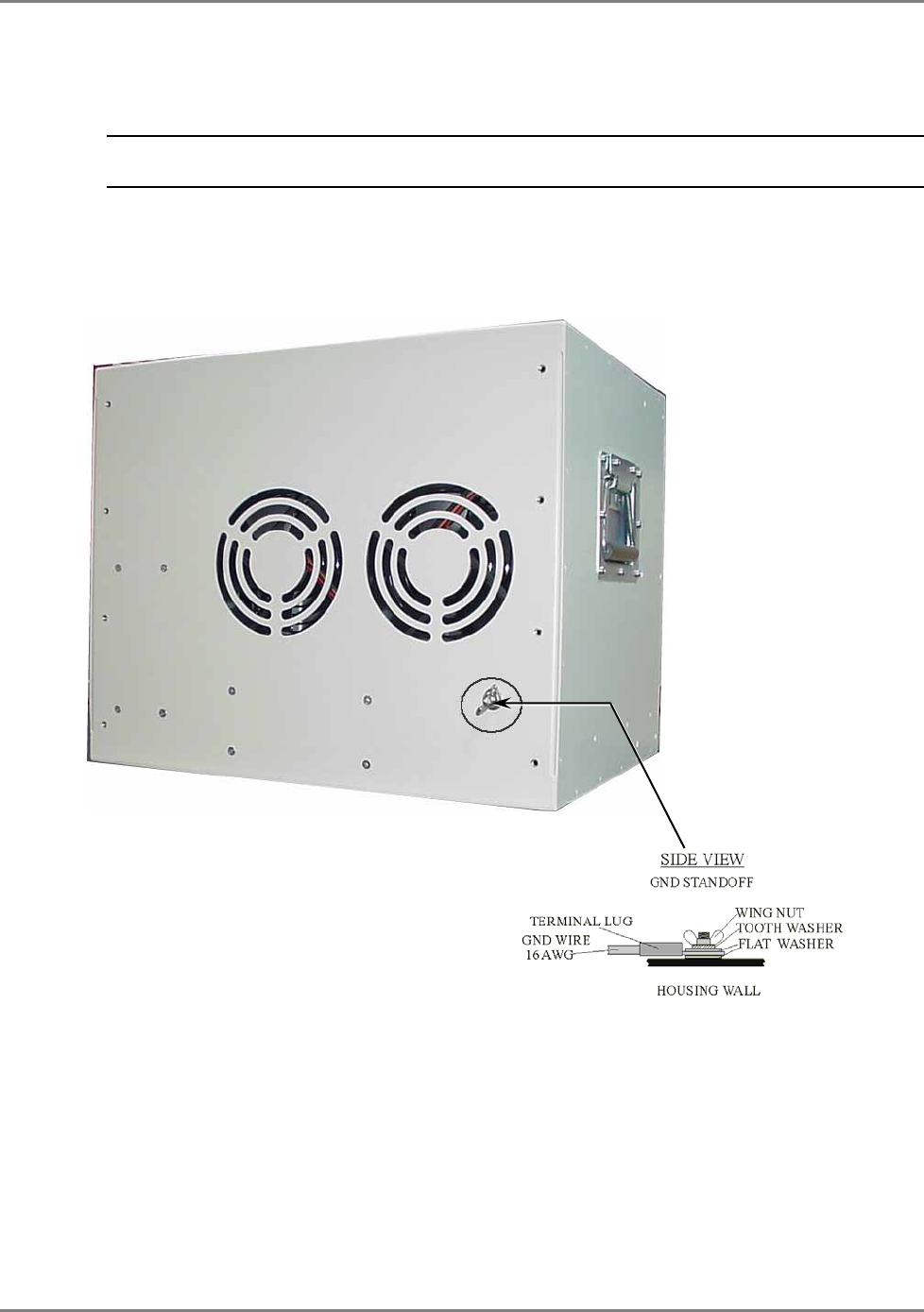
System Installation
Remote Cabinet Installation
MA 2000 Installation and Configuration Guide 50
4.3.2 RC Grounding - Integrated PS Wall Mount Model
NOTE: This procedure is only necessary for wall mount integrated power supply configuration (for other
configurations this procedure is optional).
The Ground screw is located at the rear of the unit.
Figure 4-7: Grounding Located at the Rear of the Unit
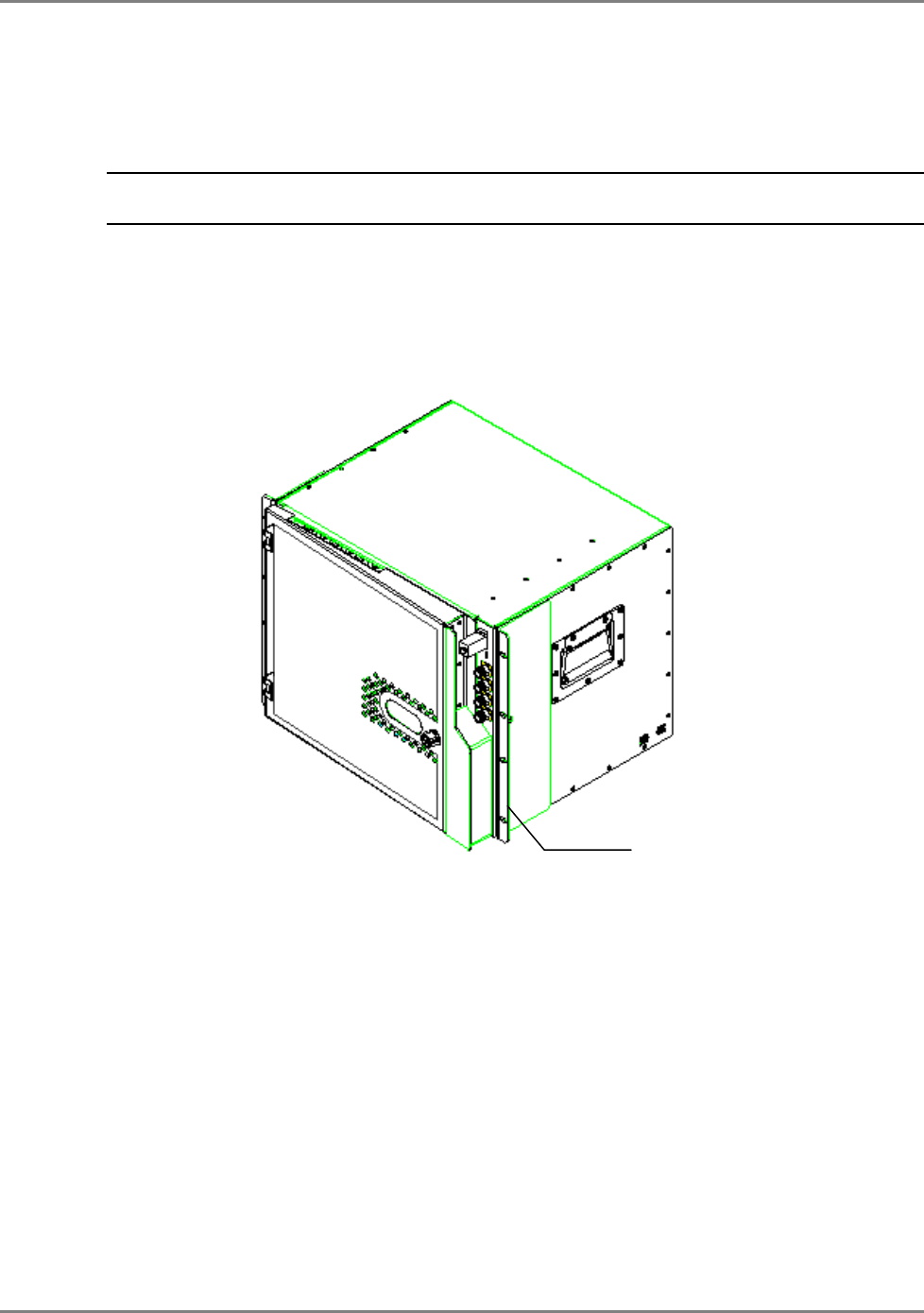
System Installation
Remote Cabinet Installation
MA 2000 Installation and Configuration Guide 51
4.3.3 RC 2000 Rack Mount Installation
NOTE: The cabinet requires a clearance of 10 cm above the unit. If a heating source is installed beneath
the MRC, a buffer must be placed between the cabinet and the surface.
The MA 2000 RC Rack Mount model is supplied with the required brackets already assembled to
the sides of the cabinet as illustrated in the following figure.
Simply, mount the MA 2000 RC in the rack and secure with the supplied screws.
Figure 4-8 . MA 2000 RC Rack Model
Rack brackets
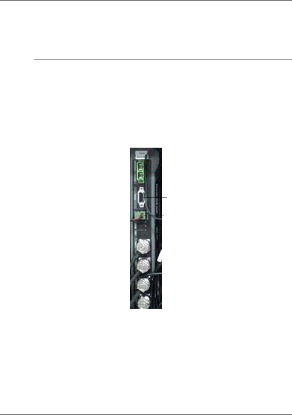
System Installation
Remote Cabinet Installation
MA 2000 Installation and Configuration Guide 52
4.3.4 Fiber Optic Connections
NOTE: Keep in mind the rules for handling and connecting F/O cables. The F/O cables will be connected to
the associated BU in the communication room at a later phase.
1. Install splice box near Remote Cabinet.
2. Connect fiber optic cable to splice box and the SC/APC pigtails to each RU 2000 module.
3. For the downlink, connect the fiber optic cable pigtails from splice box coming from the BU
port to the corresponding RU port (routing the optic fibers so they will fit through the top
opening in the door.)
4. For the uplink, connect the fiber optic cable pigtails from splice box from the RU (routing the
optic fibers so they will fit through the top opening in the door), to the uplink port that
connects to the BU.
The internal power connections and other connections should already be connected.
Figure 4-9. RU 2000 Fiber Optic and internal power connections
Power
ti
Internal connection to
Digital card
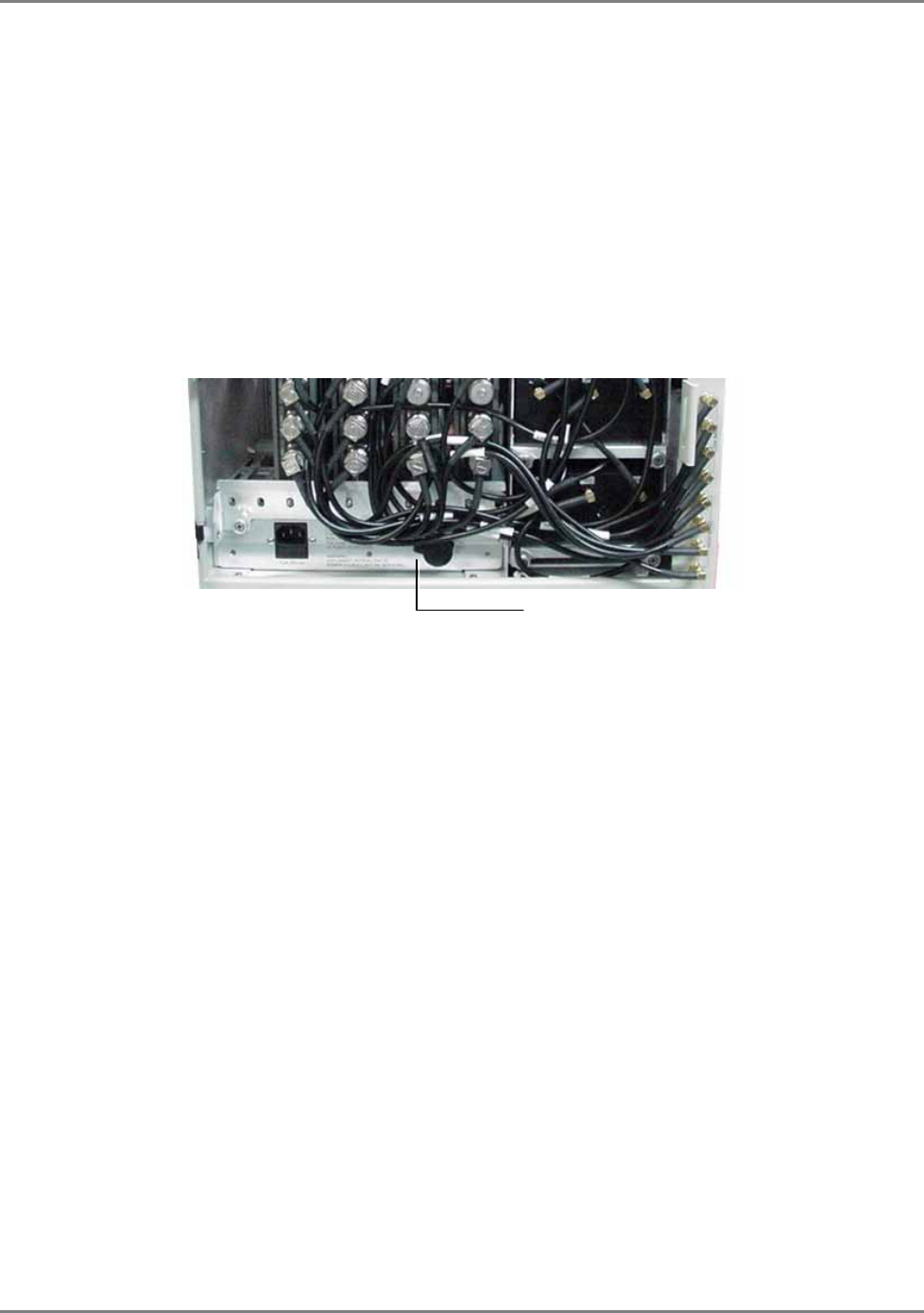
System Installation
Remote Cabinet Installation
MA 2000 Installation and Configuration Guide 53
4.3.5 Power Connections
The power connections vary depending on whether the configuration is for an integrated power
supply or for external power supplies.
4.3.5.1 Integrated Power Supply model
• Connect the AC power connector to the connector on the internal plate as illustrated
below. The power source may be: 230 VAC, 115 VAC (an AC/DC converter is built into
the chassis).
• You may also connect a backup battery of 48V to the battery connector. This is an
optional connection.
Figure 4-10. Partial View of system illustrating location of power connections
4.3.5.2 External Power Supplies Model
The external power source may be a central source with cables routed to each RU, or RU
dedicated power supplies locally installed.
• PS = 24 VDC to 48 VDC.
• Connect each power connection to the appropriate connector on the remote cabinet.
4.3.6 Antenna Connections
• For systems
without
MA 850 modules - connect the antenna connections to the RC
antenna ports;
• For systems with MA 850 modules - refer to
MA 850 Installation Manual.
Battery
connection
(l)
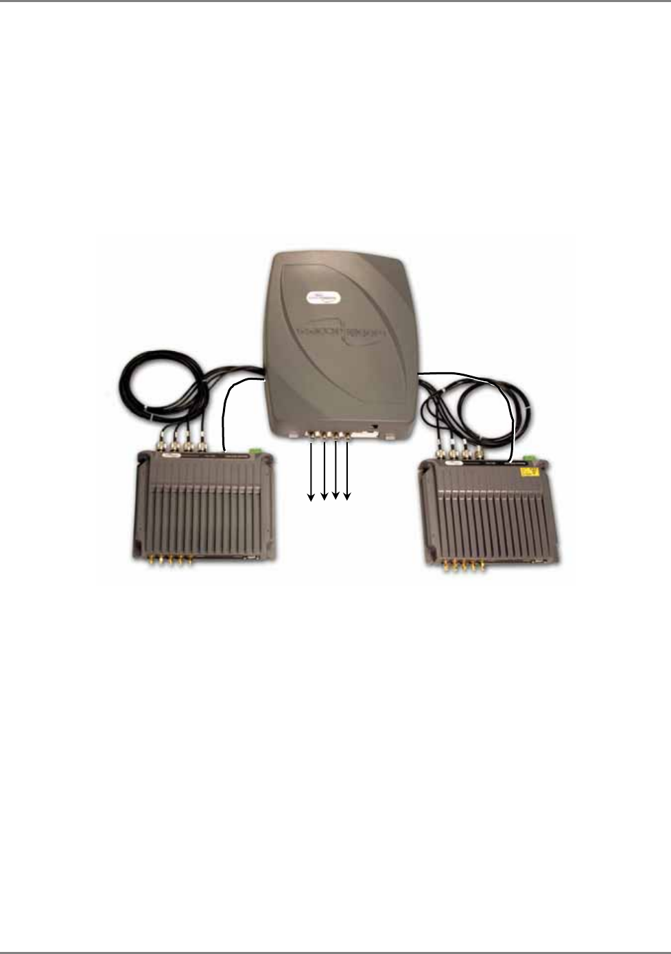
System Installation
2000 Lite Installation and Connections
MA 2000 Installation and Configuration Guide 54
4.4 2000 Lite Installation and Connections
MA 2000 is designed as a wall-mount installation – usually located in the communication shaft of
the corresponding floor. The remote units are mounted externally to the 2000 Lite device and
their antenna outputs are connected to either side of the 2000 Lite device. The combined
outputs are then connected to the antennas in the covered area.
The following figure illustrates MA 2000 connections to two RUs.
Figure 4-11. 2000 Lite System coax connections
MA 2000 Lite (filter and
combiner enclosure)
RU 2000
Antenna connections
RU 2000
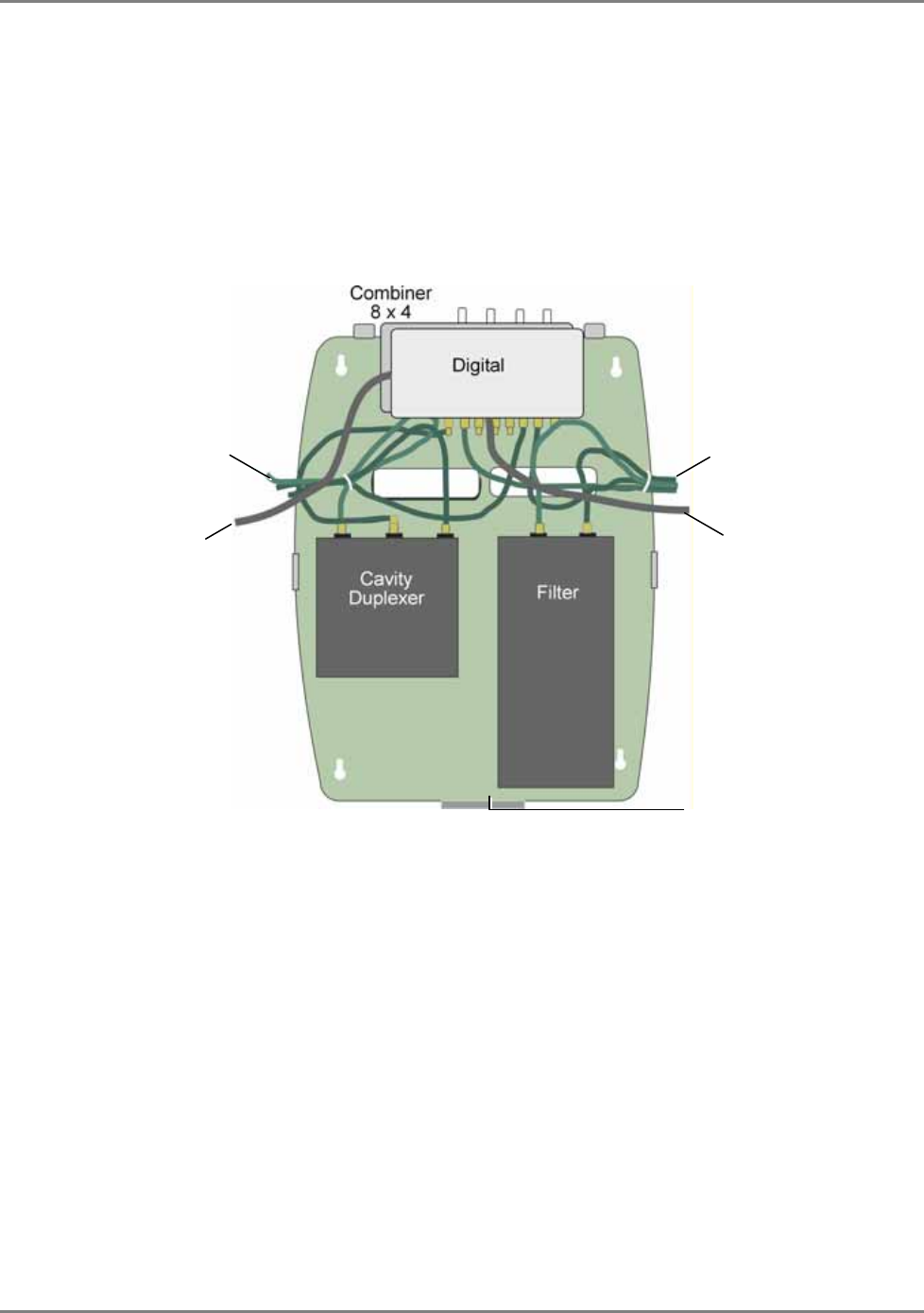
System Installation
2000 Lite Installation and Connections
MA 2000 Installation and Configuration Guide 55
4.4.1 Mounting MA 2000 Lite
In order to mount MA 2000 Lite on the wall, the cover is first removed, the tray and all installed
elements are secured to the wall and the top cover assembled again.
1. Remove the top cover by pulling it towards the rear bracket and lifting it over the front
brackets. The tray and all its assembled components is displayed. The installed filters vary
depending on the RU models in the installation.
Figure 4-12. MA 2000 Lite Prepared for Mounting
2. Depending on the tools you use:
• Either measure the distance between the four wall mount holes and drill the required
holes in the wall and insert the screws, or
• Hold the tray up against the wall and simply drill the screws in the holes.
3. Re-assemble the 2000 Lite top cover.
4. Mount each RU 2000 on the wall, on the corresponding side of the MA 2000 Lite unit.
Combiner connections
to RU RF Antenna ports
Combiner connections
to RU RF Antenna ports
Rear bracket
Digital module to RU
front panel RS232 port Digital module to RU
front panel RS232 port
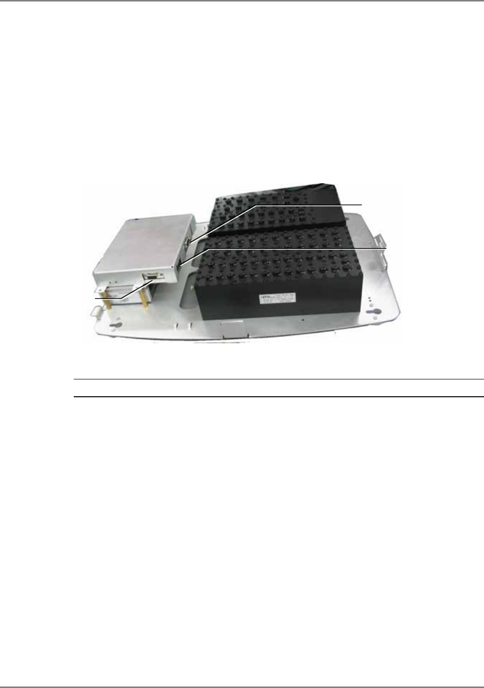
System Installation
2000 Lite Installation and Connections
MA 2000 Installation and Configuration Guide 56
4.4.2 Antenna Connections
Referring to Figure 4-12:
• Connect the four cables that are routed from the 8x4 Combiner to either side of the 2000
Lite, to the antenna ports of each RU.
• Connect the two cables that are routed from the Digital unit to either side of the 2000 Lite,
to the RS232 front panel connector of each RU.
The following figure shows the internal connections ports.
Figure 4-13. Side View of the Open MA 2000 without the Cables
NOTE: All the required RU 2000 connections are described in section
2.2.1.
• Connect the antennas to the MA 2000 Lite antenna ports.
Connection to RU front
panel RS232 port
Connection to RU front
panel RS232 port
Connection to 4x8
combiner port

MA 2000 Installation and Configuration Guide 57
5
S
Se
et
tu
up
p
a
an
nd
d
A
Ad
dj
ju
us
st
tm
me
en
nt
t
P
Pr
ro
oc
ce
ed
du
ur
re
e
NOTE: This chapter provides only the basic instructions necessary for setting up and configuring the MA
2000 System. A complete description of the NMS System is given in the
MA NMS Installation and
Configuration Guide.
5.1 Overview
After completing the required physical connections, it is required to perform some basic setup
and adjustment procedures to the MA 2000 system elements. The setup procedures are
performed through:
• A local connection to each MA 410/430 controller to which the MA 2000 head-end system
devices (BUs and RIUs) are connected
• MCT application
NOTE: The setup and adjustment procedures may also be performed through a remote connection to the
MA 430 controller using the
MA NMS
application.
The following steps are required to setup and adjust MA 2000 system devices
1. Assign an IP address (if it has not already been configured) to each MA 430 controller in
your installation (section 5.2).
2. Install the MCT application on a laptop.
3. Connect the laptop to the MA 410/430 front panel through the RS232 port.
4
.
Open a local session to the MA 410/430 controller.
5.
Verify that MA 2000 system modules are displayed in the “Network Topology” tree.
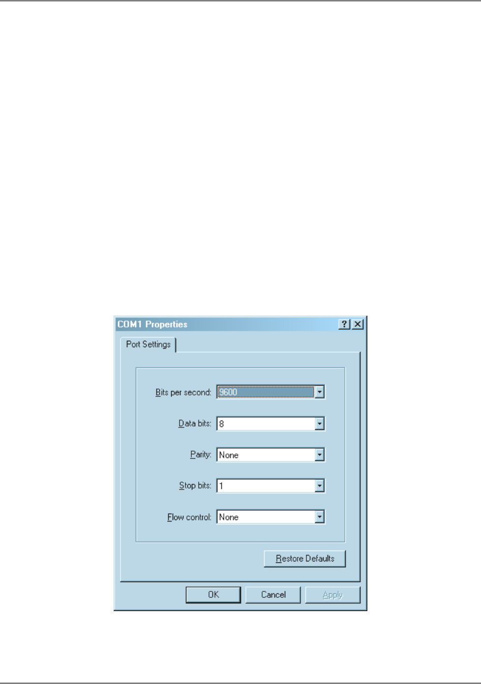
Setup and Adjustment Procedure
Configuring MA 430 Controller Network Parameters
MA 2000 Installation and Configuration Guide 58
6.
If RIUs are installed, verify that the interface between the Base Units and the RIUs is
defined as ‘RIU’ and perform the adjustment procedure described in the
RIU Products
Line Installation and Configuration Guide
.
7. If RIUs are not installed, perform the adjustment procedure described in section 0.
5.2 Configuring MA 430 Controller Network Parameters
In order to monitor the MA 430 controller and all the devices it hosts, it is required to assign a
static IP address to each MA 430 controller. This is achieved through a local connection and
configuration using a terminal emulation application such as HyperTerminal.
To configuring the MA 430 IP communication parameters
1. Connect the Laptop (or any computer) on which a terminal application (such as
HyperTerminal) is installed, to the MA 430 controller RS232 front panel connector using
cable NMS-PC-DB9.
2. Launch the terminal emulation application and set the communication settings as follows:
9600 bps, 8 data bits, no parity, 1 stop bit, no flow control. The following figure shows the
HyperTerminal Port Settings dialog.
.
Figure 5-1. Terminal Emulation Application Settings
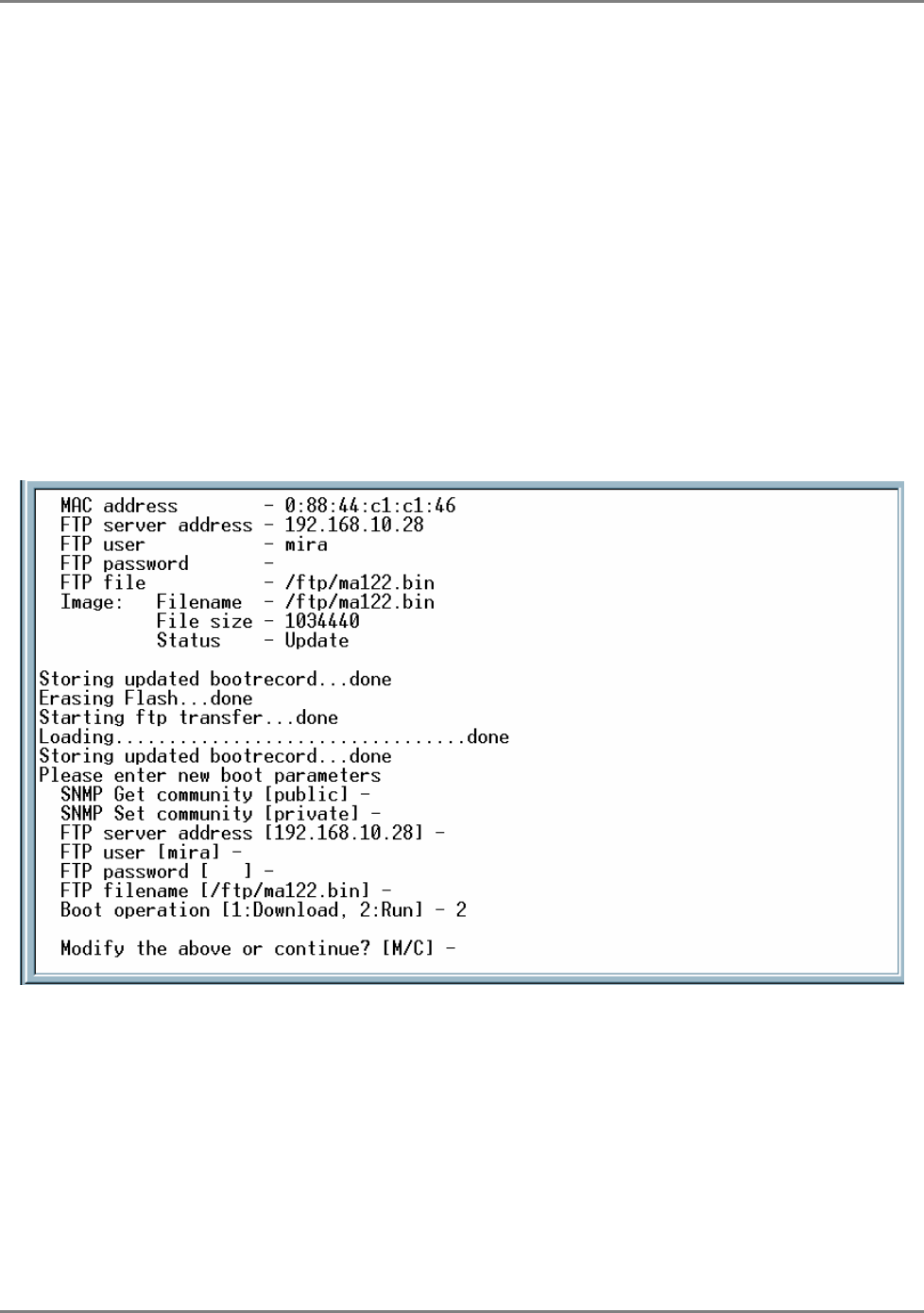
Setup and Adjustment Procedure
Configuring MA 430 Controller Network Parameters
MA 2000 Installation and Configuration Guide 59
3. Reset the MA 430 controller by removing and reinserting the power connector on the
controller rear panel. The terminal application will be initialized.
4. Press any key within 5 sec in order to access the CLI command prompt.
5. At the password prompt, enter the default password “MA” and change the password if
desired.
6. Respond to the IP Address prompts by entering the IP Address, Subnet mask and Default
Gateway address for the MA 430 to which you are connected.
7. Respond to the Community name prompts, make any necessary changes (default Get =
Public, default Set = Private).
8. Respond to the Boot Operation prompt by selecting 2: RUN.
9. Remove the RS232 connection.
10. Connect the MA 430 rear panel COM connector to the network.
Figure 5-2. Defining IP Address Parameters
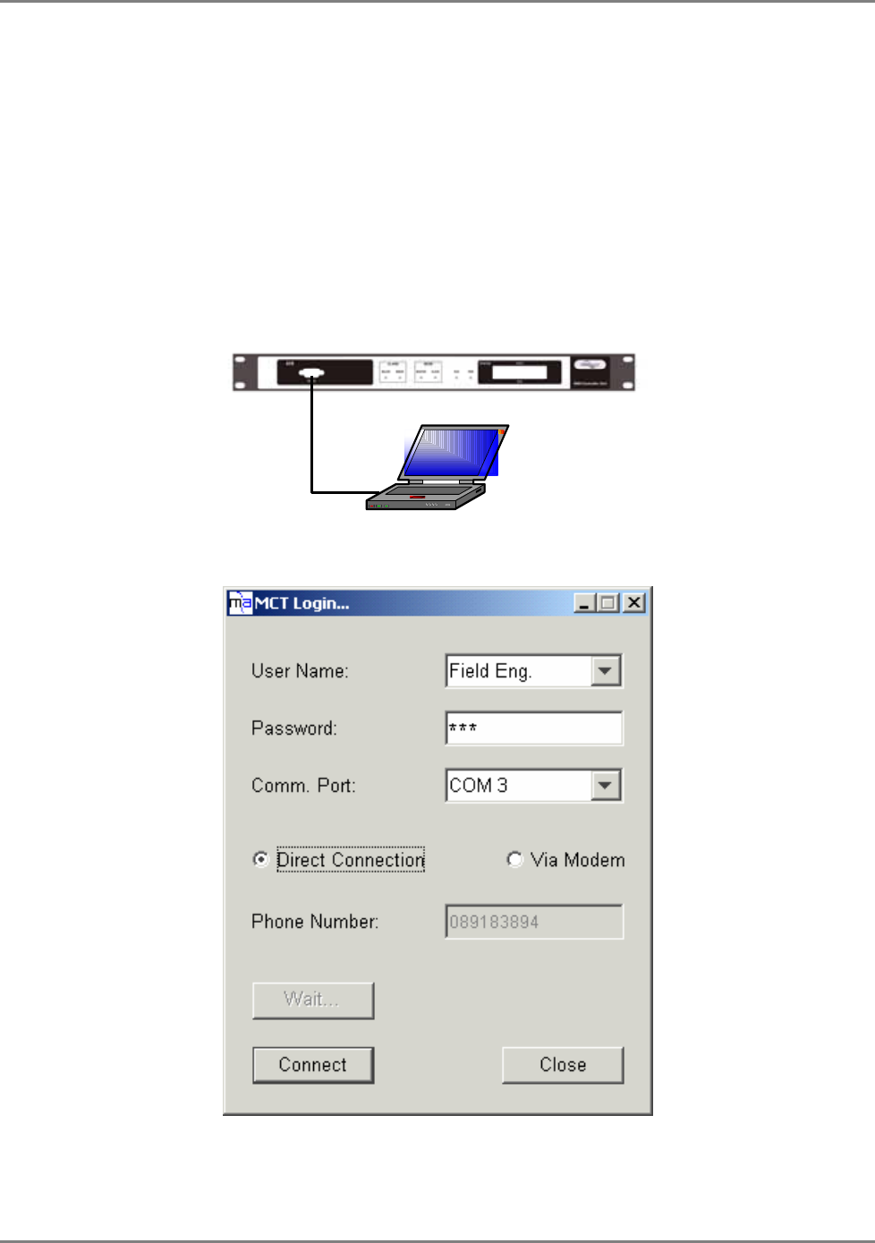
Setup and Adjustment Procedure
Opening a Controller Session
MA 2000 Installation and Configuration Guide 60
5.3 Opening a Controller Session
The configuration procedure is performed through a computer that is serially connected to the
MA 430 controller.
Install MCT on a computer (or laptop) meeting the requirements specified in the datasheet and
create a shortcut to the application on your desktop.
To connect to the controller locally
1.
Connect the computer on which the MCT application is installed to controller RS232 front
panel connector, as illustrated below.
2.
Launch the MCT application by double-clicking on the MCT icon on the desktop. The Login
dialog appears.
Figure 5-3. MCT Login dialog
Laptop with MCT
application
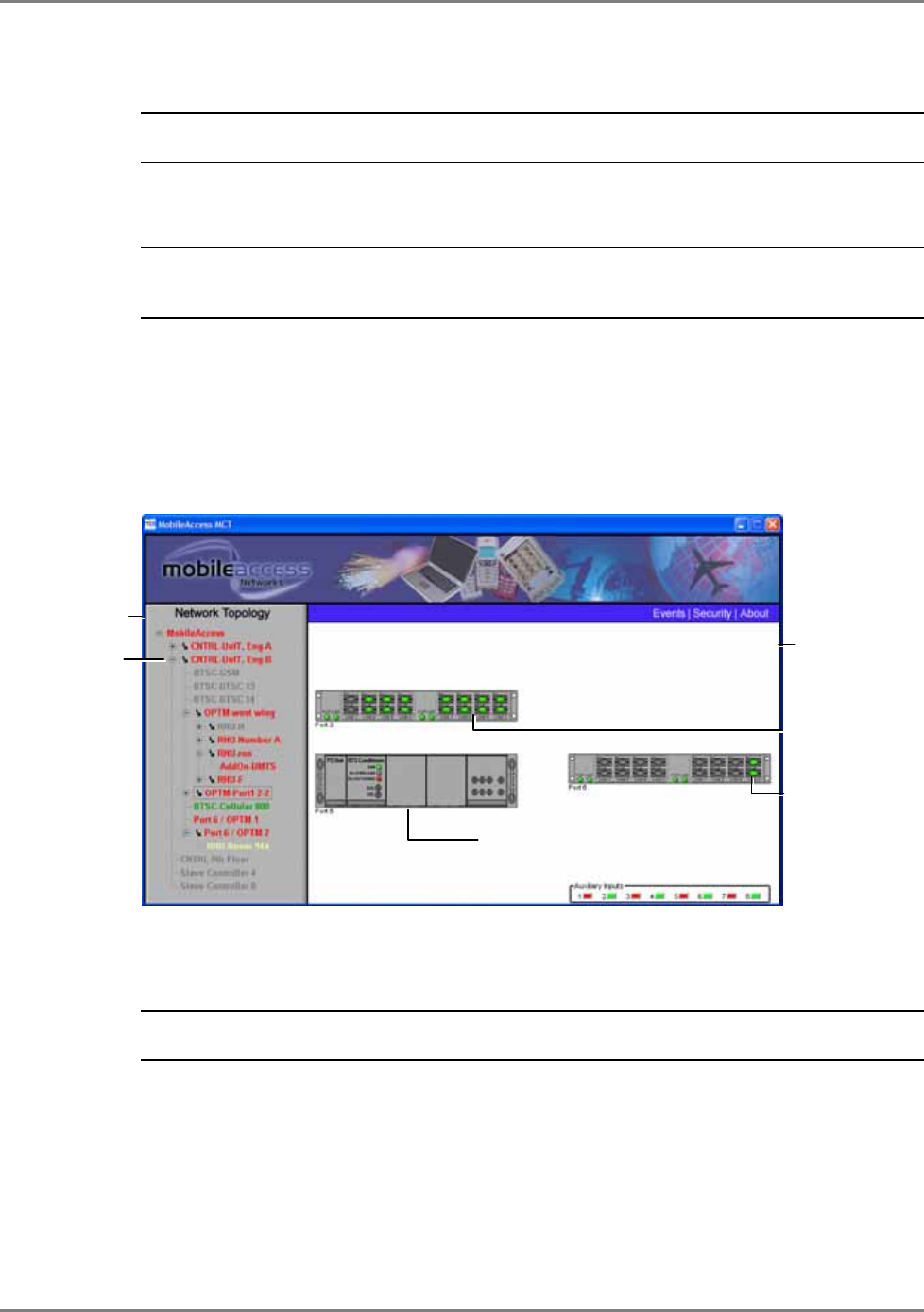
Setup and Adjustment Procedure
Opening a Controller Session
MA 2000 Installation and Configuration Guide 61
3.
To open a session at a level that provides access to configuration options, select the User
Name ‘Field Eng’ and enter the default Engineering password ‘Eng’.
NOTE: The User Names determine the access levels. For more information on the User Names,
Passwords and Password change, refer to the NMS manual.
4.
Select the Comm Port according to the communication port to which your computer is
connected.
NOTE:
To determine the communication port on your computer, right-click on the My Computer icon,
select the Hardware tab, click Device Manager and under Ports, the communication port identification
will be displayed.
5.
Click Connect. The MCT main window appears. The window contains the Topology Tree
that displays the currently installed and defined modules, and the Display Area showing
graphical displays of the units.
Each element has a separate configuration dialog that is accessed by double-clicking either
on the corresponding node in the Network Topology tree or on the element view in the
Display Area.
Figure 5-4. MCT Main window
6. Verify that the modules are identified in the Network Topology tree.
NOTE: The nodes may be displayed in, green, red or yellow since the adjustment procedure has not
yet been preformed.
RIU showing the installed BTSC
modules. Double-click on the
module to access its dialog.
T
opology Tree Display area
Double-click to
invoke OPTM dialog.
Double-click to
invoke RU dialog.
MA 430
Controller
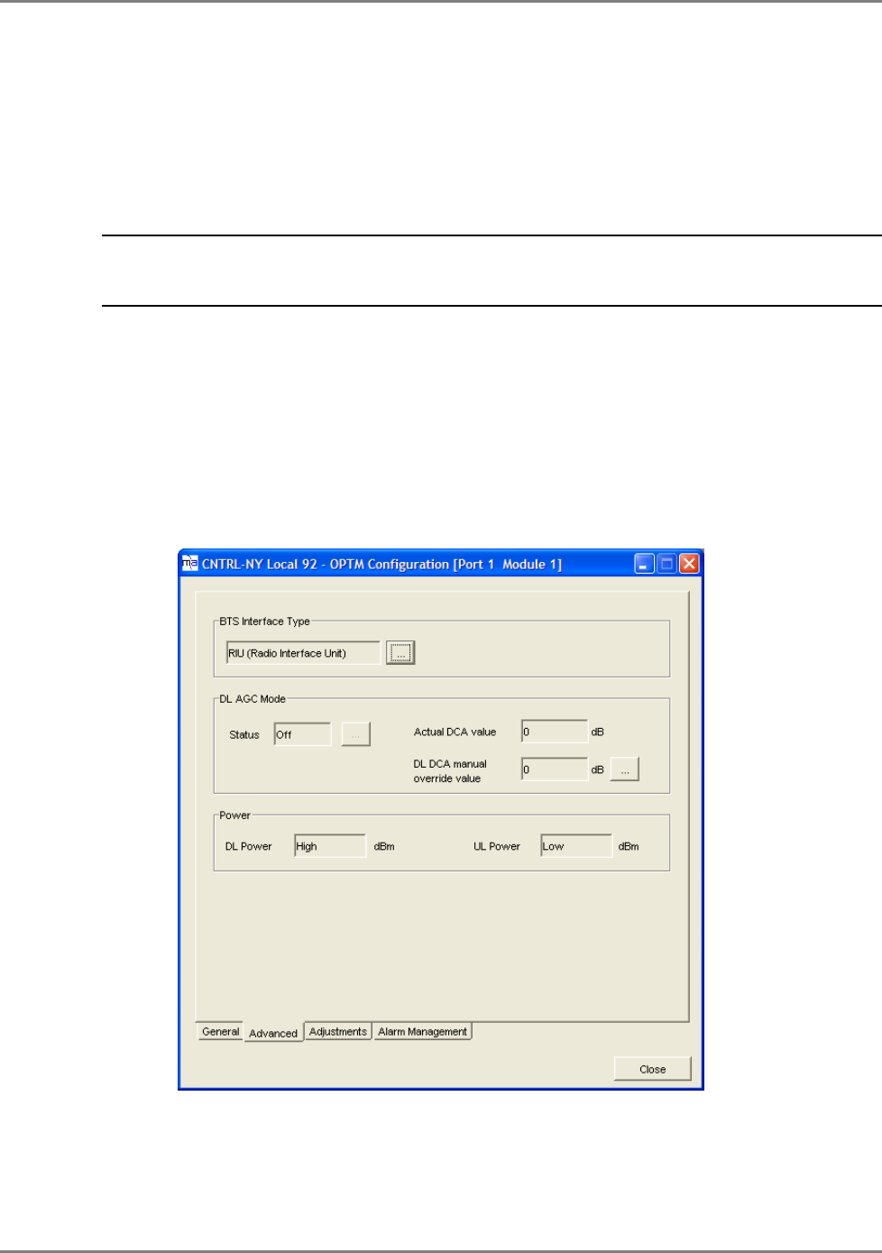
Setup and Adjustment Procedure
Base Units Interface Definition
MA 2000 Installation and Configuration Guide 62
5.4 Base Units Interface Definition
By default, the Base Units are factory configured to connect to a passive BTS/BDA interface type.
If an RIU is included in the installation, the BTS/BDA interface for each BU must be defined
accordingly.
NOTE: The relevant Base Units are displayed under the group of host BTSC module(s) In the Topology
Tree. Each Base Unit is displayed according to its 4-port modules, where each 4-port module is referred to
as OPTM.
To verify and modify the Base Unit interface configuration
1. To invoke the BU configuration dialog, do one of the following:
• Double-click on the first OPTM node in the tree, or
• Double-click the
empty space
in the OPTM in the Base Unit view.
Do not click on the
LEDs in the OPTM –
this will invoke the RU configuration dialog.
2.
Click the Advanced tab. In the BTS Interface Type field, verify that the correct option is
selected: RIU or Passive, according to the BTS/BDA interface.
Figure 5-5: OPTM Configuration Dialog
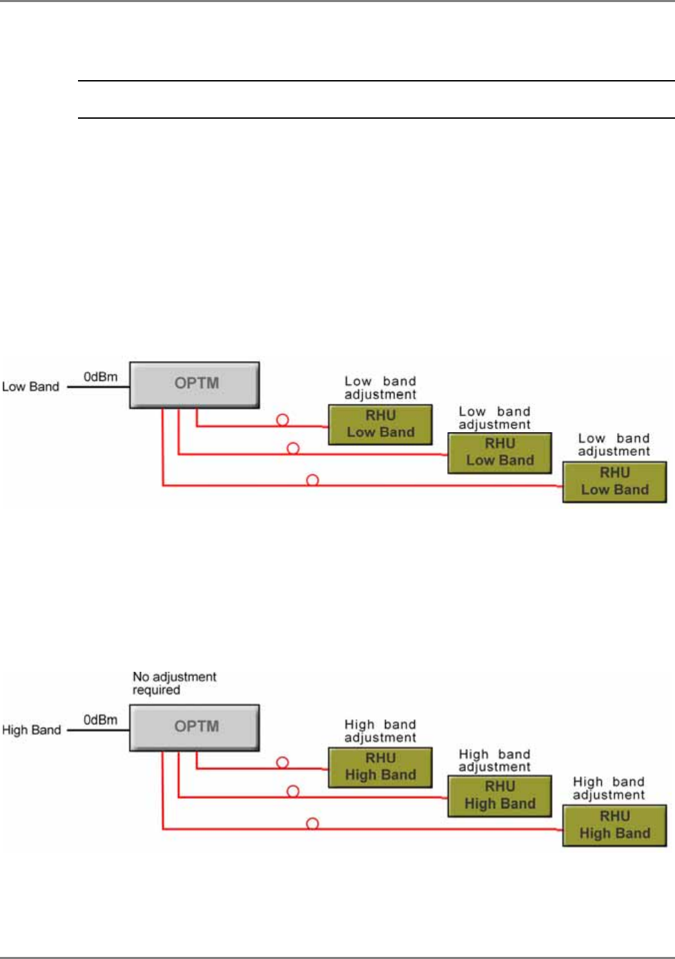
Setup and Adjustment Procedure
Adjustment Procedure
MA 2000 Installation and Configuration Guide 63
5.5 Adjustment Procedure
NOTE: If your system includes RIU Chassis/Lite systems, refer to the RIU Product Line Installation and
Configuration Guide for detailed instructions on commissioning, configuring and monitoring RIUs.
This procedure may be performed for systems without RIUs. Although the adjustment
procedure is optional and the system will operate without it, the procedure contributes to
optimal site coverage.
The adjustments are performed at each band, where the OPTM and relevant remotes RUs are
adjusted at the low band, and only the RUs and add-on units are adjusted for each additional
band.
To adjusts sites without RIUs
1. Referring to the DS (1000/2000) for the required composite signal input to the BU for the
number of carriers and the bands, inject the low band signal at the appropriate power
directly to the OPTM.
2. Adjust the RU as follows:
• Invoke the RU configuration dialog by double-clicking on the RU in the Topology Tree
or Display View.
• Click the Adjustment tab, and click Adjust.
3. Referring to the DS (1000/2000) for the required composite signal input to the BU for the
number of carriers and the bands, inject the high band signal at the appropriate power
directly to the OPTM.
4. Adjust the OPTM as follows:
• Invoke the OPTM configuration dialog by double-clicking on the OPTM in the Topology
Tree or Display View.

Setup and Adjustment Procedure
Adjustment Procedure
MA 2000 Installation and Configuration Guide 64
• Click the Adjustment tab, verify that Live Signal is selected and click Adjust.
5. Adjust the RU as follows:
• Invoke the RU configuration dialog by double-clicking on the RU in the Topology Tree
or Display View.
6. Click the Adjustment tab, and click Adjust
7. Repeat steps 5 to 7 for any additional bands.

MA 2000 Installation and Configuration Guide 65
6
U
Up
pg
gr
ra
ad
di
in
ng
g
a
an
nd
d
C
Co
on
nf
fi
ig
gu
ur
ra
at
ti
io
on
n
E
Ex
xa
am
mp
pl
le
es
s
MA 2000 provides an entry level cost effective solution for current services and support for
future services from the same or different operators. Support for additional bands is
implemented by an RU module and RU specific hardware designed to prevent interference with
other existing bands in the coverage area.
For support for additional services, connect the corresponding RU and hardware (Cavity Filter,
Duplexer, etc.) to the 8x4 Module and to the external coax infrastructure.
NOTE: It is required to order an Accessory Kit for each new unit to be added to the installation. The kit
includes cables for connecting the RU 2000 or MA 1200 add on units to the required filters. Because of the
differences in cable length requirements, the accessory kit differs for units designated to be installed in
2000 Cabinets and for those designated to be installed with MA 2000 Lite systems. Be sure to order the
appropriate kit as detailed in section
1.3 - MA 2000 Element Models under the appropriate section.
This chapter provides several examples of the most common configurations and their
connections. As systems are upgraded, refer to the provided diagrams for a description of the
connections between the Remote Units (referred to as RU or RU 2000), the interface
devices (Filters, etc.) and the 4x8 Combiner.
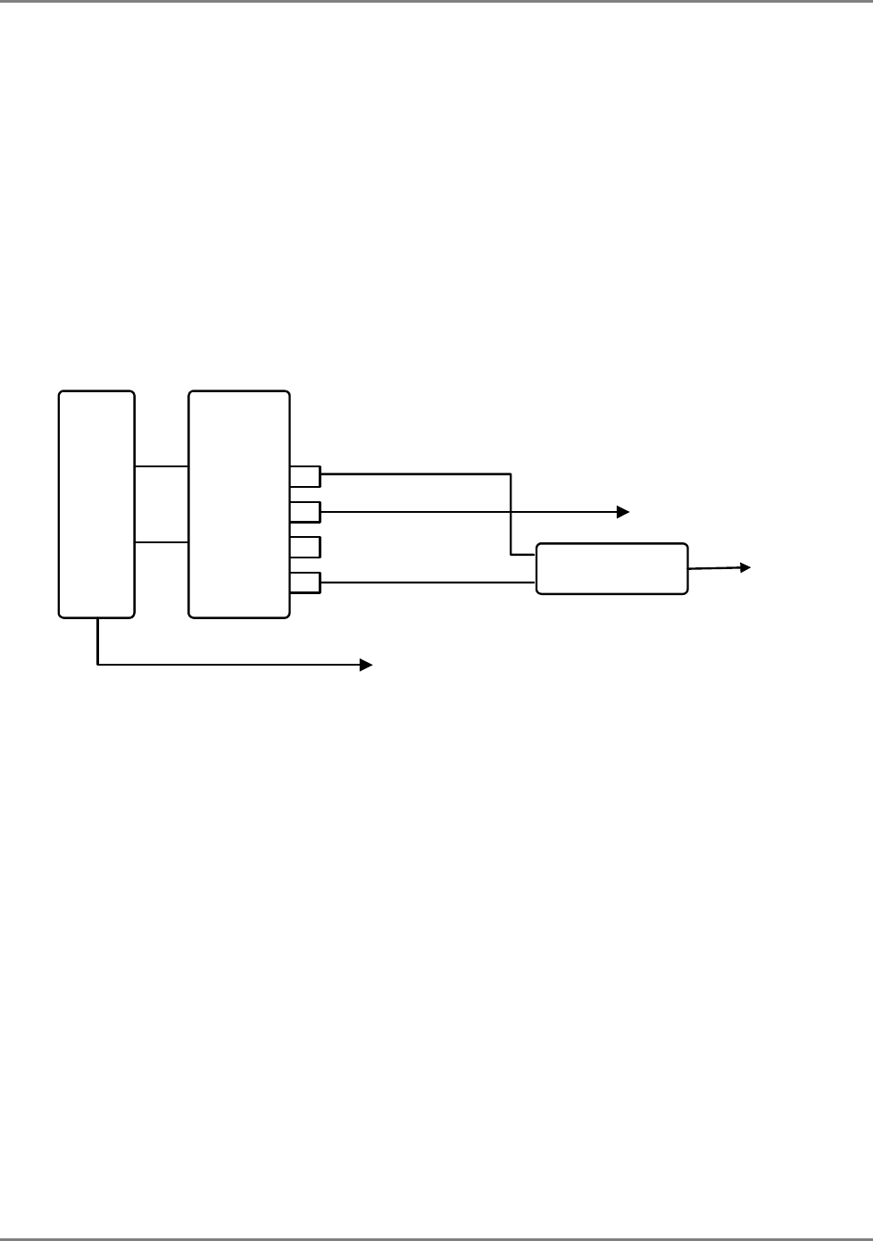
Upgrading and Configuration Examples
Common USA Configurations
MA 2000 Installation and Configuration Guide 66
6.1 Common USA Configurations
6.1.1 iDEN/SMR with PCS Add-on
iDEN and SMR coverage is implemented by one remote unit. This type of configuration was
designed to meet Nextel’s existing needs. MA 1200 add-on module for PCS support can be
integrated into the solution at any time in order to meet future needs.
The following figure describes the port connections between the remote units, add-on, and 8x4
Combiner.
P1
P4
P3
P2
RHU 2000
iDEN/SMR
iDEN/SMR
Cavity Duplexer
iDEN DL
N.C.
SMR DL and iDEN UL
Add-on
1200
PCS
DL
UL
8x4 P6
Com
8x4 P2
8x4 P3
SMR UL
Figure 6-1. iDEN/SMR and PCS Connections
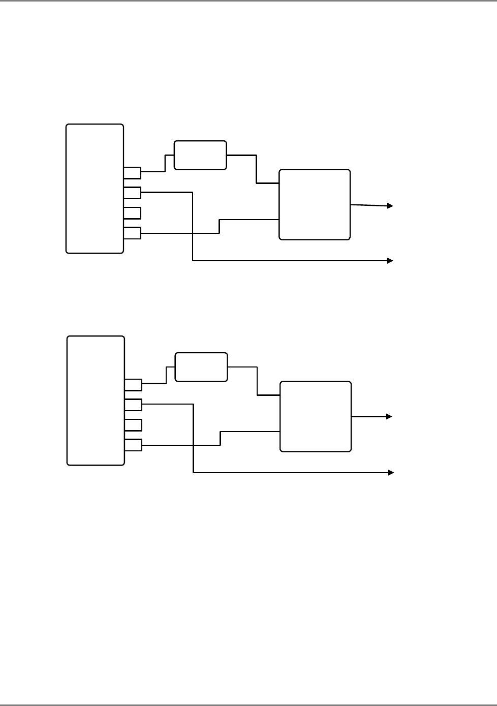
Upgrading and Configuration Examples
Common USA Configurations
MA 2000 Installation and Configuration Guide 67
6.1.2 Cell/PCS
For infrastructures supporting a single Cell band and PCS, connect the RU according to the
following figure.
P1
P4
P3
P2
RHU 2000
CELL/PCS Cavity
Cell Duplexer
N.C. 8x4 P1
8x4 P5
Cavity
Cell DL
Tx
Rx
Com
Figure 6-2. Single Cell/PCS Connections
For infrastructures supporting two Cell bands and a PCS band, connect the second Cell/PCS
services RU according to the following figure.
P1
P4
P3
P2
RHU 2000
CELL/PCS Cavity
Cell Duplexer
N.C. 8x4 P4
8x4 P8
Cavity
Cell DL
Tx
Rx
Com
Figure 6-3. Additional Cell/PCS Connections
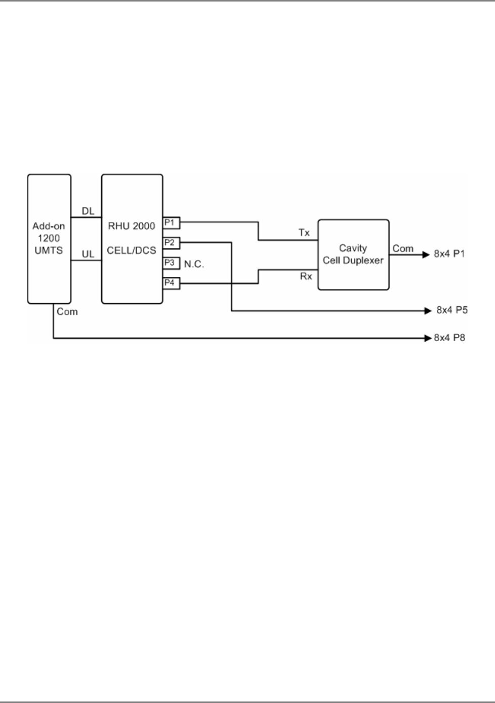
Upgrading and Configuration Examples
Common Israeli Configurations
MA 2000 Installation and Configuration Guide 68
6.2 Common Israeli Configurations
MA 2000 Lite supports Cell/DCS and Orange/DCS. UMTS support can be added through MA 1200
Add-on.
6.2.1 Cell/DCS
Figure 6-4. Cell/DCS and UMTS Configuration
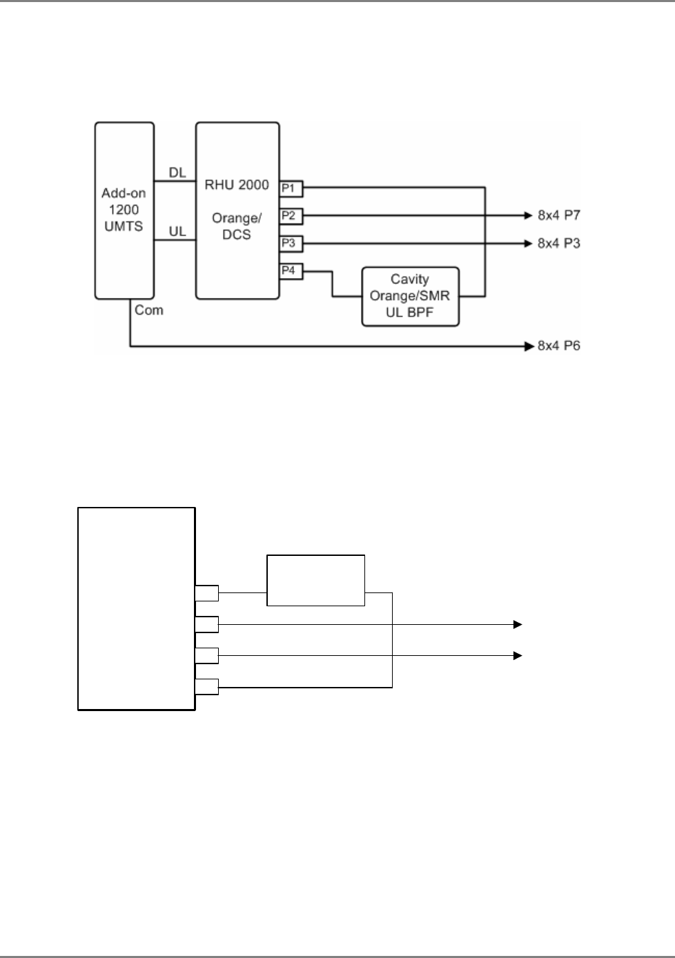
Upgrading and Configuration Examples
Common Israeli Configurations
MA 2000 Installation and Configuration Guide 69
6.2.2 Orange/DCS and UMTS Add-on
Figure 6-5. Orange/DCS and Add-on UMTS Configuration
6.2.3 iDEN
iDEN support is provided through MA 2000 Cabinet configurations.
RHU 2000
iDEN
P1
P2
P3
P4
Cavity
iDEN
DL BPF
to 8x4 P6
to 8x4 P2
6-6. iDEN Configuration

MA 2000 Installation and Configuration Guide 70
7
A
Ap
pp
pe
en
nd
di
ix
x
I
I:
:
O
Op
pt
ti
ic
ca
al
l
t
te
es
st
t
P
Pr
ro
oc
ce
ed
du
ur
re
es
s
7.1 General
Two parameters are of prime importance when testing optical cables or jumpers for use with
Mobile Access products:
• Optical Loss – the difference between the optical power at the input and
output of an optical cable. It must be measured (usually in dB units) at
1310 nm. The maximum allowable loss should be < 0.5 dB/km for Single
Mode (SM) cables and < 0.5 dB for every mated pair of connectors.
• Optical Backreflection – the percentage of light backreflected from the
fiber input (dB units). The maximum allowable backreflection should be < –
55 dB for all jumper cables.
The methods to test these parameters will be described below.
7.2 Optical Loss Testing
This section describes the optical loss testing of a Single Mode Cable with SC/APC connectors
at each end.
7.2.1 Required Test Equipment
• 1310 nm Stabilized Laser Source
• 1310 nm Optical Power Meter
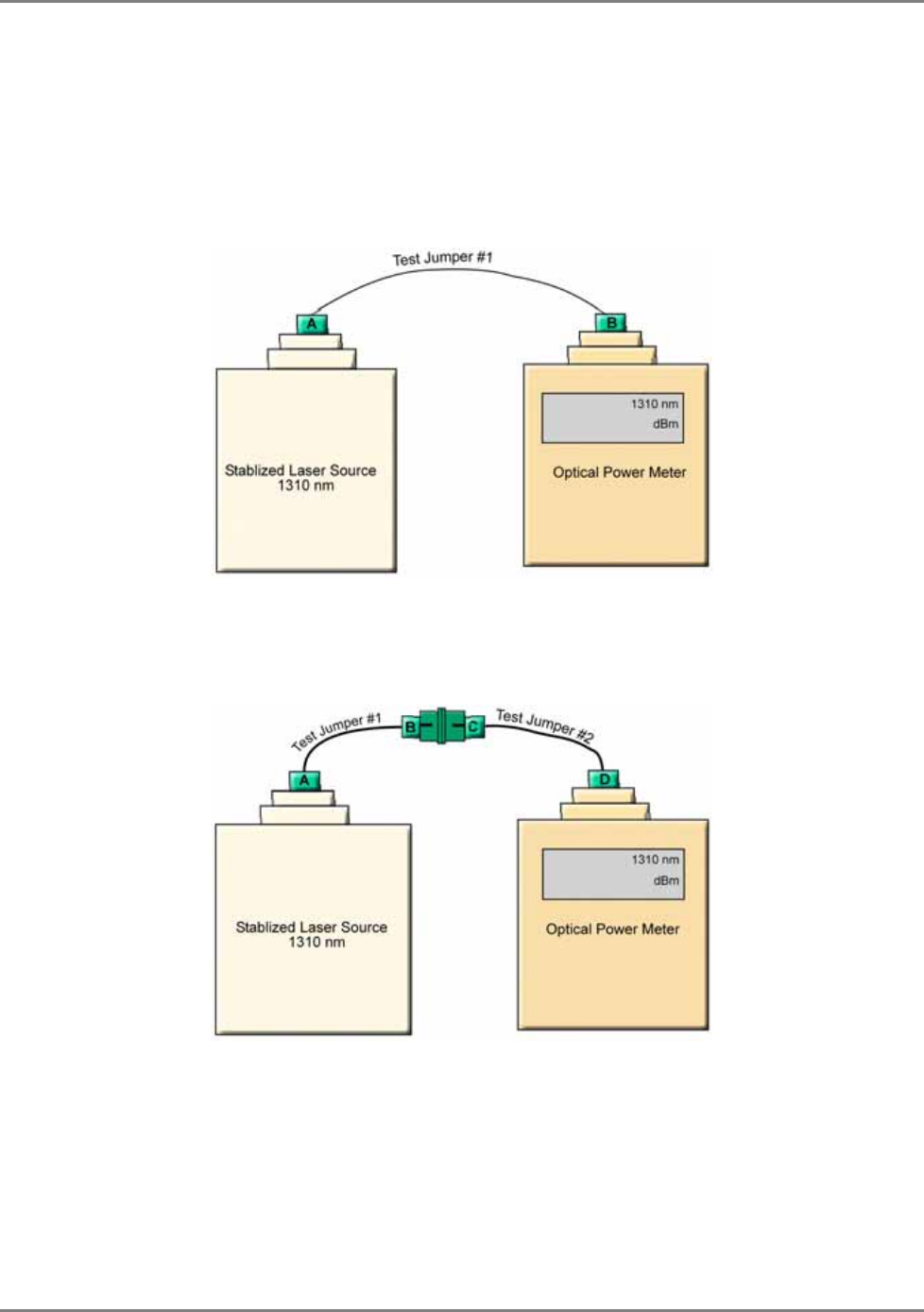
Appendix I: Optical test Procedures
Optical Loss Testing
MA 2000 Installation and Configuration Guide 71
• Two Fiber Optic Test Jumpers with SC/APC connectors at each end
• Two SC/APC Adapters
7.2.2 Test Procedure
1. Set up the Laser Source, Optical Power Meter, and Test Jumper as shown
below.
Figure 7-1. Set Up
2. Record reading as P1 in dBm units.
3. Serially connect the second Test Jumper as shown below.
Figure 7-2. Serial Connection of Second Jumper
4. Record the Power Meter Reading as P2 in dBm units.
5. Calculate Loss L12 according to the equation: L12 = P1 - P2
6. If L12 is lower than 0.5 dB continue to Step-7; otherwise replace these test
cables and repeat from Step-1.
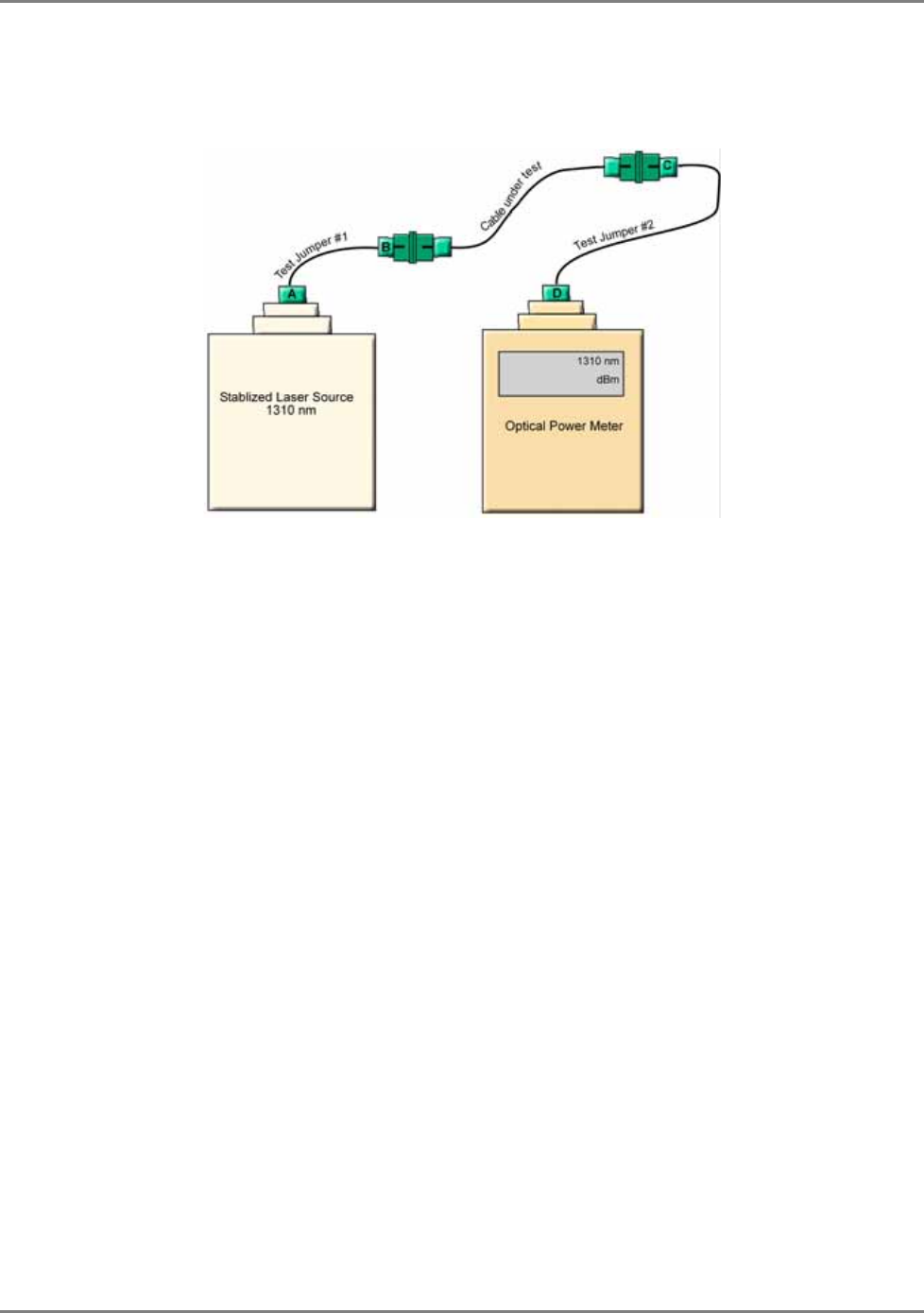
Appendix I: Optical test Procedures
Optical Loss Testing
MA 2000 Installation and Configuration Guide 72
7. Disconnect connectors B and C. Connect the Cable Under Test (CUT)
between connector B and C as shown below.
Figure 7-3. Connecting CUT
8. Record Power Meter reading as Pcut in dBm units.
9. Calculate Cable Loss Ldut from the equation Lcut = P2- Pcut.
10. The maximum allowable loss should be < 0.5 dB/km for SM cables and <
0.5 dB for every mated pair of connectors.
7.2.3 Example
Testing a 50 meter cable with SC/APC connectors at each end.
• P1 = -1dBm
• P2 = -1.5dBm
• L12= P1 – P2 = -1dBm - (-1.5) = 0.5 dB
Conclusion: the test cables are of sufficient quality to continue testing.
• Pcut = -2dBm
• Lcut = P2 - Pcut= -1.5dBm - (-2dBm) = 0.5 dB
This is acceptable since a mated connector pair was added along with the CUT and a loss of
-0.5 dB is allowed for every mated pair of connectors.
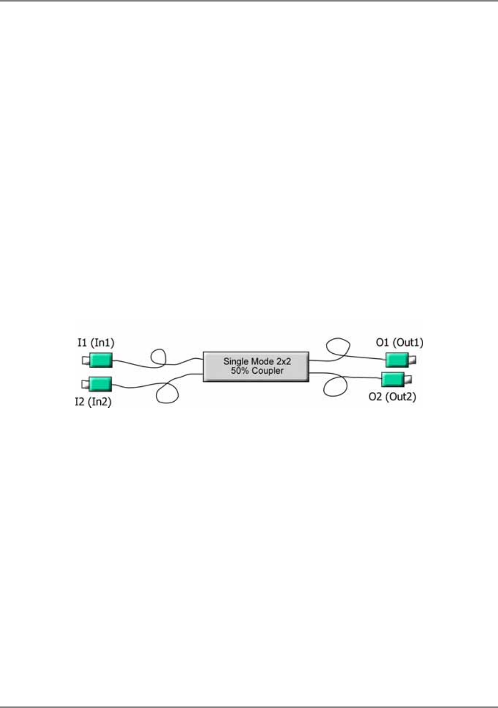
Appendix I: Optical test Procedures
Optical Back-reflection Testing
MA 2000 Installation and Configuration Guide 73
7.3 Optical Back-reflection Testing
This section describes the optical back-reflection testing of SM SC/APC connectors at each
end of an optical cable.
7.3.1 Required Test Equipment
1. Adjustable1310 nm Stabilized Laser Source with output power greater than 7dBm
2. 1310 nm Optical Power Meter with a measurement range of up to -70 dBm
3. One low loss Singlemode 1310 nm 2x2 50%/50% Fiber Optic Coupler with SC/APC
connectors at all four fiber pigtailed ports. Pigtail length should be 50 cm.
4. One SC/APC Adapter
7.3.2 Test Procedure
1. Refer to the following figure for port definitions of the Fiber Optic Coupler. The coupler is
symmetrical but for our purposes, each port should be identified as shown in Figure 1-4.
Figure 7-4. Port Identification
2. Measure the loss from port I1 to O1 according to the insertion loss method described in the
previous section. This loss will be referred to as LI1O1. It should be approximately 3.5 dB.
3. Measure the loss from port O1 to I2 in a similar manner. This loss will be referred to as
LO1I2. It should also be approximately 3.5 dB.
4. Calculate Total Loss, TL where TL= LI1O1 + LO1I2. TL should approximately 7dB.
5. Adjust the laser output power in dBm to the same value as TL.
For example, if TL = 7dB, adjust the laser output to 7 dBm.
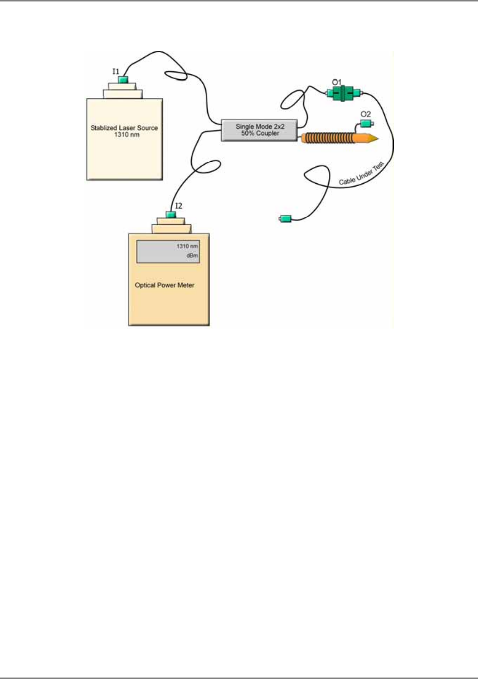
Appendix I: Optical test Procedures
Optical Back-reflection Testing
MA 2000 Installation and Configuration Guide 74
6. Connect the laser to port I1 of the coupler as shown in Figure 7-5.
Figure 7-5. Test Procedure Connections
7. Connect the Power Meter to port I2 of the coupler as shown in Figure 7-5.
8. Wrap the O2 pigtail around a pencil of diameter 7 to 8 mm as illustrated.
9. The power meter readings should be < –58 dBm; otherwise, clean connector O1 and
measure again.
10. Connect the cable under test to connector O1.
11. Record Power Meter Reading as Backreflection, BRcut, of the cable under test. The power is
measured in dBm units. This is the same value as the backreflection.
For example, if the power meter shows –58 dBm, the backreflection is –58 dB. The
maximum backreflection from the SC/APC connectors should be < –57 dB.
Long cables will have a higher BR since the cable itself reflects a small amount of light. This
small amount can grow to a considerable amount over a long length of fiber. To factor out this
cable backreflection, perform a mandrel wrap on the cable adjacent to the connector under test
and perform all measurements with the mandrel wrap.