Corning Optical Communication MA850 In Building RF Distribution System User Manual UM 850 02Aug04
Corning Optical Communication Wireless In Building RF Distribution System UM 850 02Aug04
UserManual.wiki
>
Corning Optical Communication
>
MA850 User Manual
User Manual
Navigation menu
Upload a User Manual
Namespaces
Wiki Guide
HTML
PDF
Info
Views
User Manual
Discussion / Help
Navigation
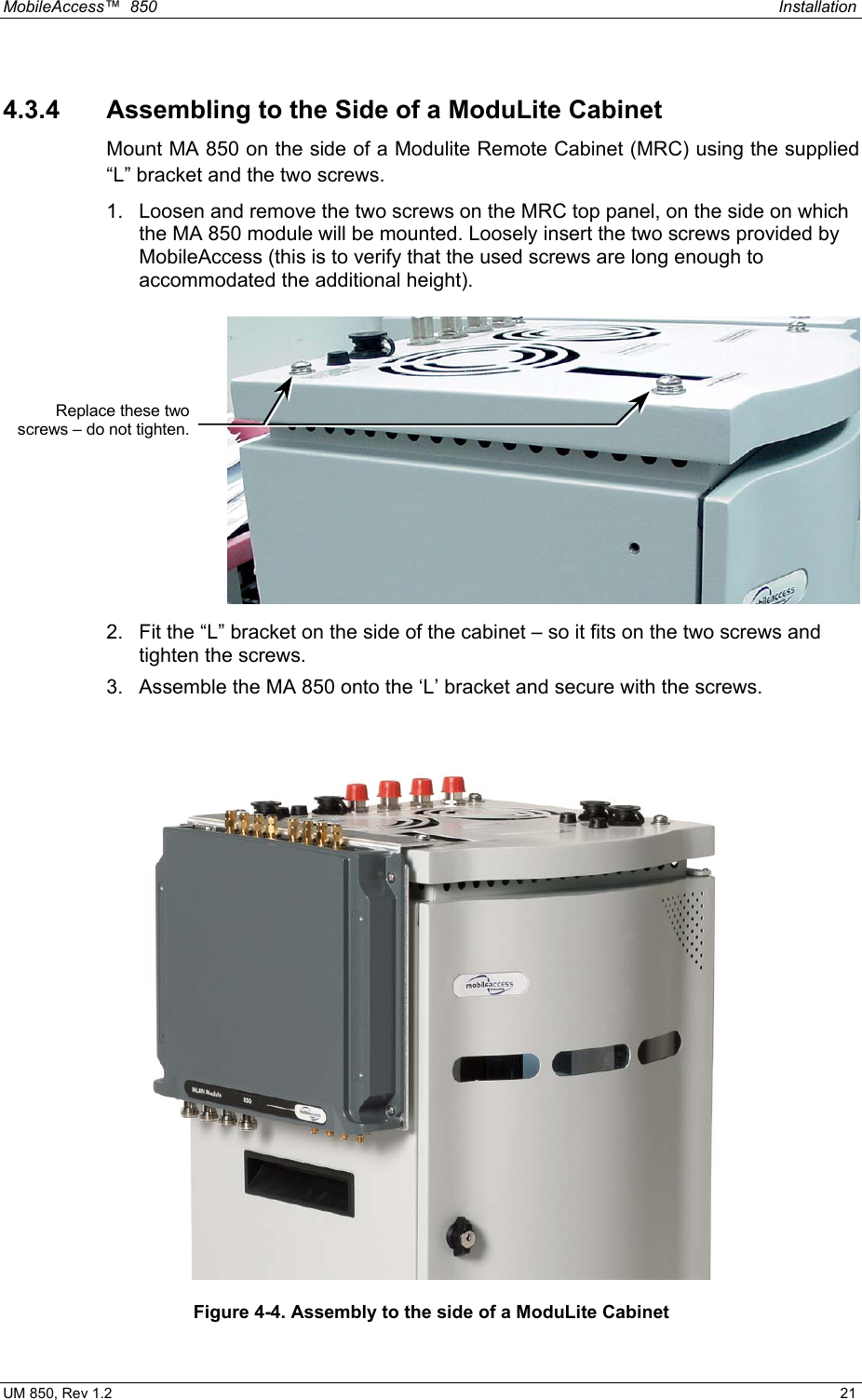
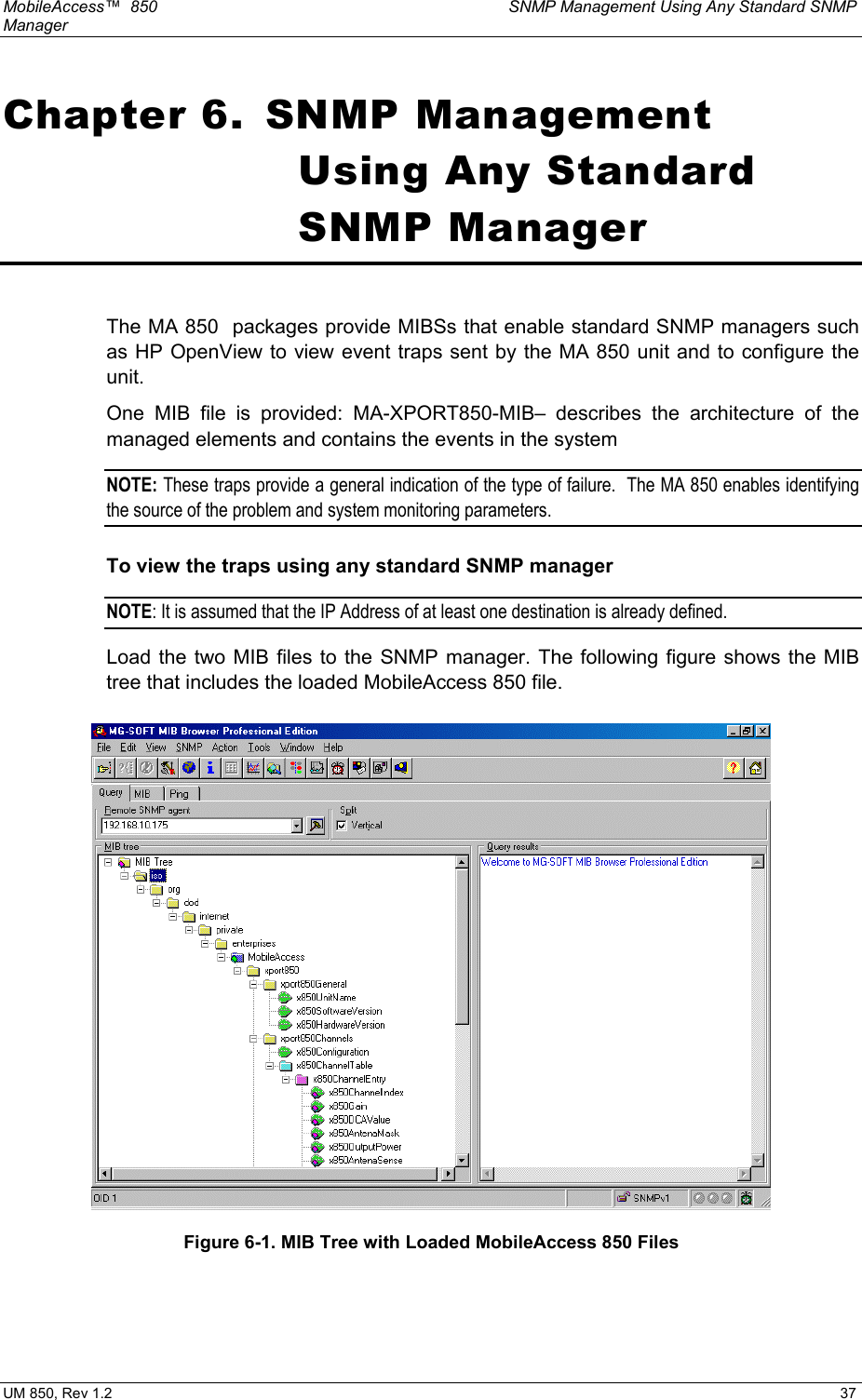
![MobileAccess™ 850 Infrastructure Preparation UM 850, Rev 1.2 15 • Cable runs that span less than two floors should be secured to suitably located mechanical structures. • The cables should be supported only from the building structure. 3.2.2 Additional Information • Use coax ½”, 50ohm, male-to-male N-type, (6-7dB for 1Ghz, 11dB for 2Ghz) for connecting to MRC ports. • Use VSWR meter (Site Master) for checking coax cables, including the antennas. (<2). • Unconnected MA 850 ports should be terminated with a 50 ohm load. 3.3 In-building Antennas The in-building antennas are connected to the coaxial cable distribution system by jumper cables at various points. The antennas will be mounted on the ceiling tiles and should be exposed. All in-building antenna installations will be such that it will not interfere with indoor traffic and will not enable any person to touch the antennas. • Wideband antennas omni/directional – up to 2.5GHz to support 802.11b/g, up to 6GHz to support 802.11a • 50 ohm impedance NOTE: The following vendor antennas have been verified. Although most other broadband antennas can be used, it is recommended to contact your MobileAccess representative to verify that your antennas are suitable for use with your installed MobileAccess system. Antennas: Vendor Catalog number Gain [dBi] Mars Antennas MA-CM36-15 2 low band 3-4 high band 5 WLAN 802.11b Cellwave A08818DC00-28T0 2.1 Antenna Specialists ASP-3561 2](https://usermanual.wiki/Corning-Optical-Communication/MA850/User-Guide-459226-Page-15.png)