Corning Optical Communication MA860WCE 860 Mobile Access WLAN Solution User Manual Manual
Corning Optical Communication Wireless 860 Mobile Access WLAN Solution Manual
UserManual.wiki
>
Corning Optical Communication
>
MA860WCE User Manual
>
Manual
Contents
1.
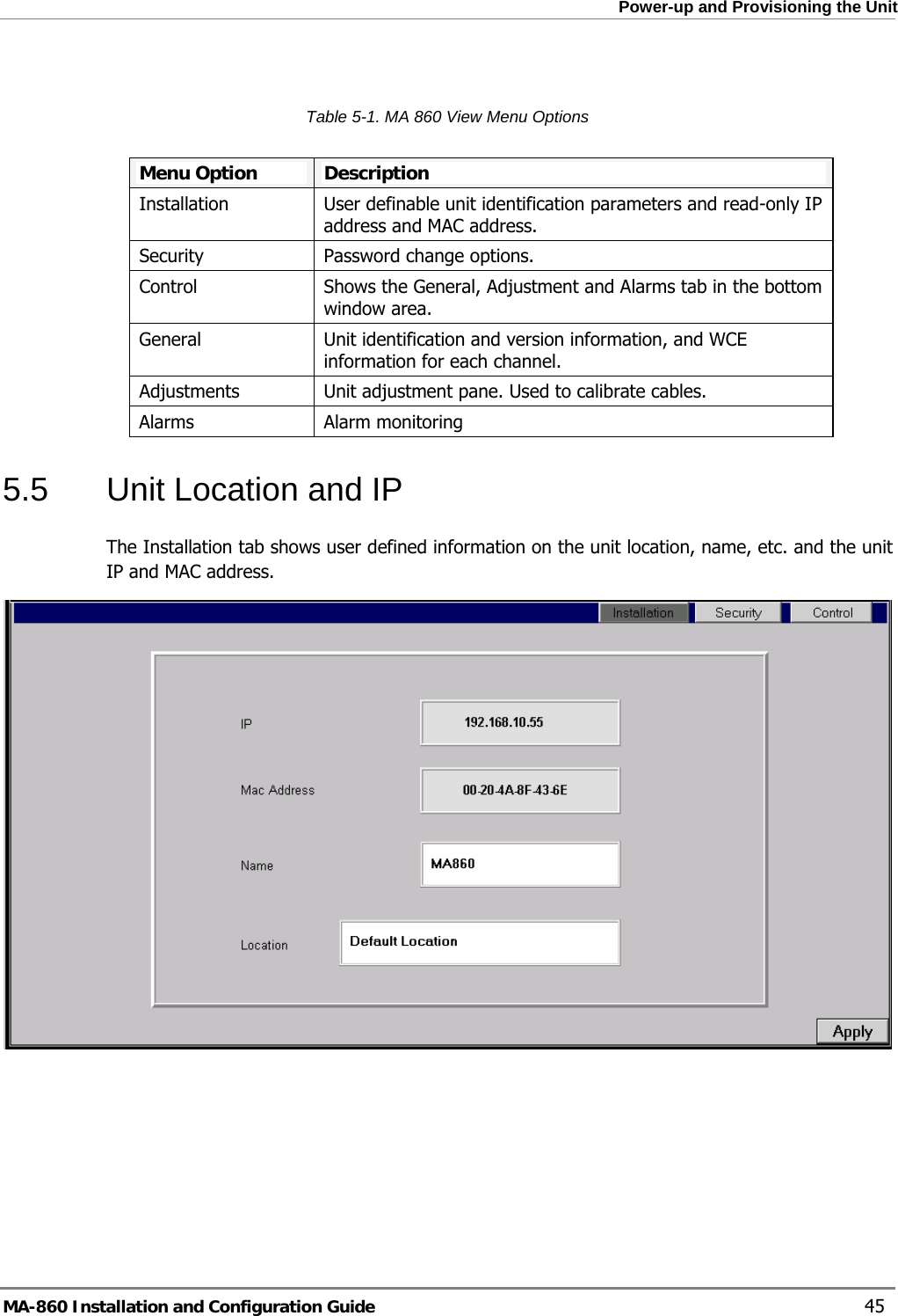
USERS MANUAL 1
2.
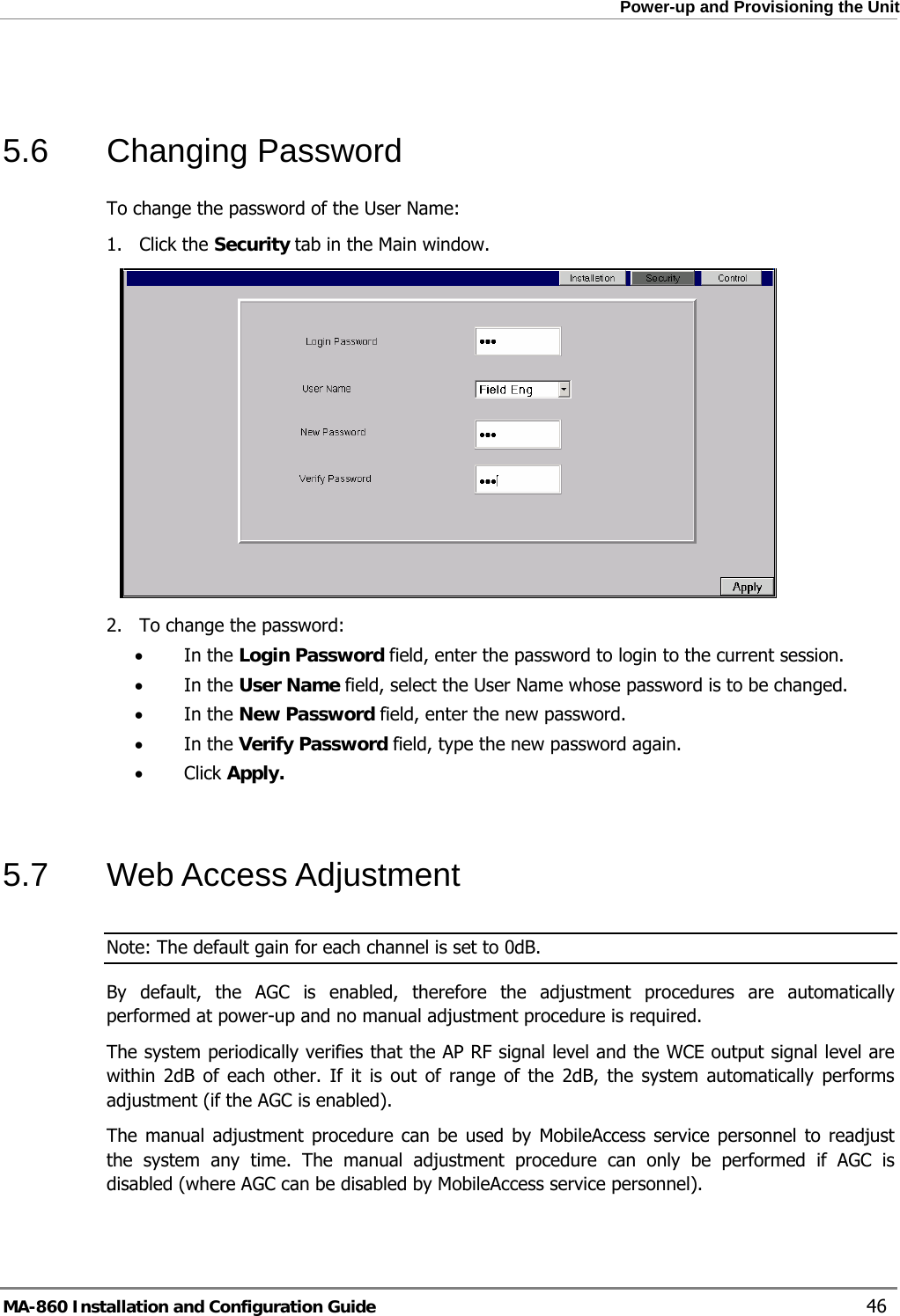
USERS MANUAL 2
3.
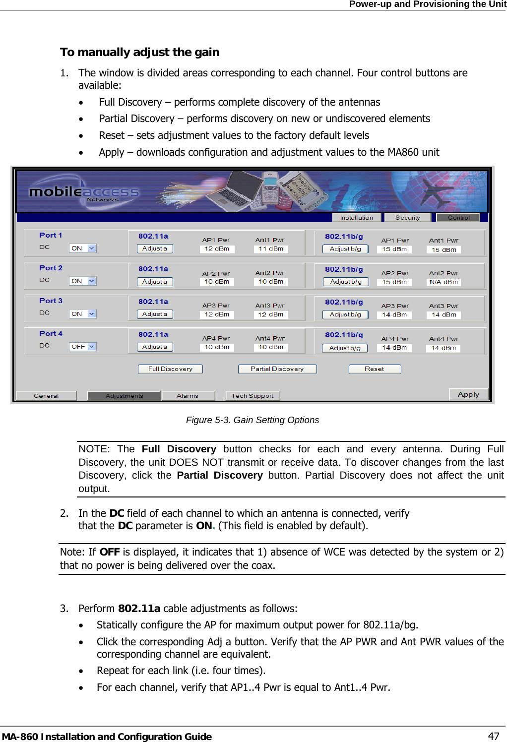
USERS MANUAL 3
4.
Manual
Manual
Navigation menu
Upload a User Manual
Namespaces
Wiki Guide
HTML
PDF
Info
Views
User Manual
Discussion / Help
Navigation