Corning Optical Communication MA860WME 860M WITH WCE User Manual MA860 UM 10 Feb 08
Corning Optical Communication Wireless 860M WITH WCE MA860 UM 10 Feb 08
Contents
- 1. USERS MANUAL 1
- 2. USERS MANUAL 2
- 3. USERS MANUAL 3
USERS MANUAL 2

Infrastructure Preparation
MA-860 Installation and Configuration Guide 19
3.5.3 AP Termination
A 50 Ω
ΩΩ
Ω termination is required on each unused AP port. The type of termination is vendor
specific.
Vendor Model Termination
Cisco 1242 RP-TNC 50 ohm terminators
Aruba AP-70 RP-SMA 50 ohm terminators
Trapeze MP-422 RP-SMA 50 ohm terminators
Colubris MAP-330 RP-SMA 50 ohm terminators
Meru AP-200 RP-SMA 50 ohm terminators
3.5.4 IDF Access Point Planning
MobileAccess recommends that each independent IDF Telecom closet is adequately planned for
installation of the access points to increase the amount of isolation and reduce the amount of RF
leakage between access points.
MobileAccess recommends the following options for access point installation:
•Wall Mounting of MobileAccess supported Access Point
•Rack-Mounting of MobileAccess supported Access Points
Utilizing the mounting hardware distributed from each supported access point vendor, Access
point can be mounted on a wall within the IDF or telecom closet and connected with the
appropriate low-loss jumper cables to the appropriate 860 WLAN module interface ports.
MobileAccess has also found that mounting the access points in a 19” rack system has proven to
be effective against RF leakage between access points. In this configuration,
two access points
can be installed per 19” shelving unit which takes up 1U of space per two access points.

Installation
MA-860 Installation and Configuration Guide 20
4 I
In
ns
st
ta
al
ll
la
at
ti
io
on
n
This chapter contains the installation and connection procedures for various installation
configurations. The MobileAccess 860 WLAN Module and system architecture may be installed in
the following configurations:
4.1 Accessory Kits
Verify that the supplied accessory kit corresponds to your installation. The accessory kits include
a bracket, the required cables and accessories.
Part Number Description
AK-860-1000 RHU 1000 860 WLAN Accessory Mounting Kit
AK-860-1200 RHU 1200 860 WLAN Accessory Mounting Kit
AK-860-MDLT Modulite 860 WLAN Accessory Mounting Kit
AK-860-2000 MRC 2000 860 WLAN Accessory Mounting Kit
AK-860-2000L MRC 2000L 860 WLAN Accessory Mounting Kit
AK-860-SA Stand alone Mounting Kit
AK-860-PS-9.8V-75W (Optional) Redundant Power Supply Kit
4.2 Access Point Installation (Recommendation)
MobileAccess recommends that each independent IDF Telecom closet is adequately planned for
installation of the access points to increase the amount of isolation and reduce the amount of RF
leakage between access points. MobileAccess recommends the following options for access
point installation:
•Wall Mounting of MobileAccess supported Access Point
•Rack-Mounting of MobileAccess supported Access Points
Utilizing the mounting hardware distributed from each supported access point vendor, Access
point can be mounted on a wall within the IDF or telecom closet and connected with the
appropriate low-loss jumper cables to the appropriate 860 WLAN module interface ports.
Installation
MA-860 Installation and Configuration Guide 21
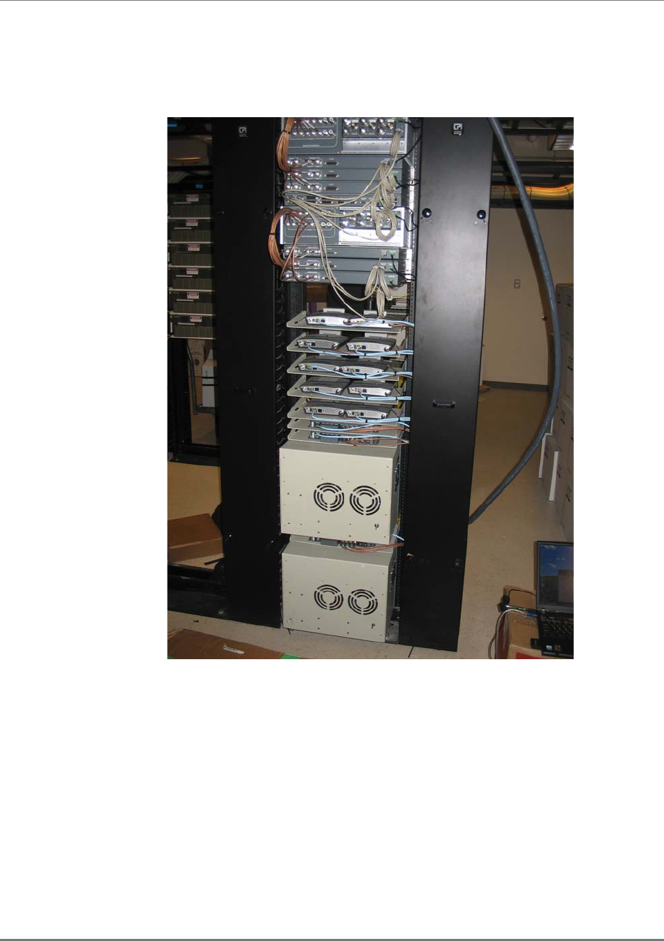
MobileAccess has also found that mounting the access points in a 19” rack system has proven to
be effective against RF leakage between access points. In this configuration as detailed in the
picture below, two access points can be installed per 19” shelving unit which takes up 1U of
space per two access points.
Installation
MA-860 Installation and Configuration Guide 22
4.3 Wi-Fi Coverage Expander (WCE) Installation
Note: It is assumed the antennas have already been installed at the remote locations.
A WCE unit is installed near each antenna. The WCE can be installed in the following
configurations:
•Tie-Wrap / Wire-Tie to a fixture
•Wall Mounted – using four screws
•In-line with the coax cables
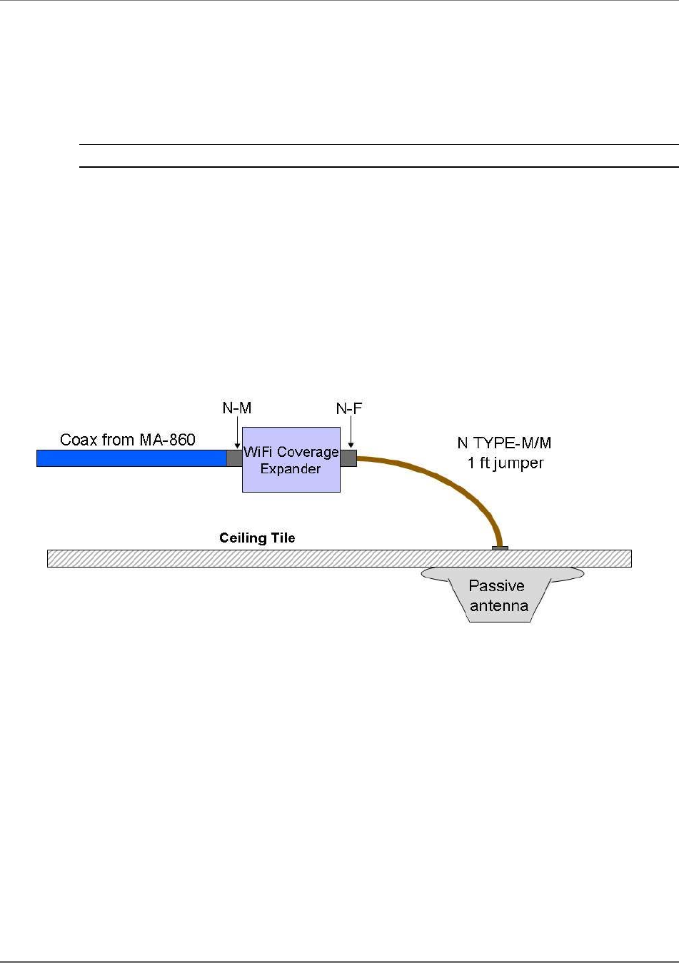
The WCE will be connected on one side to a 0.5'' low loss coaxial cable (typically running to a
remote wiring closet), and to the Passive Broadband Antenna usually through a jumper (flexible
1' coax cable). The following sections illustrate each type of WCE installation.
0.5'' low loss coaxial cable
Up to 250 ft 1' coax cable
Installation
MA-860 Installation and Configuration Guide 23
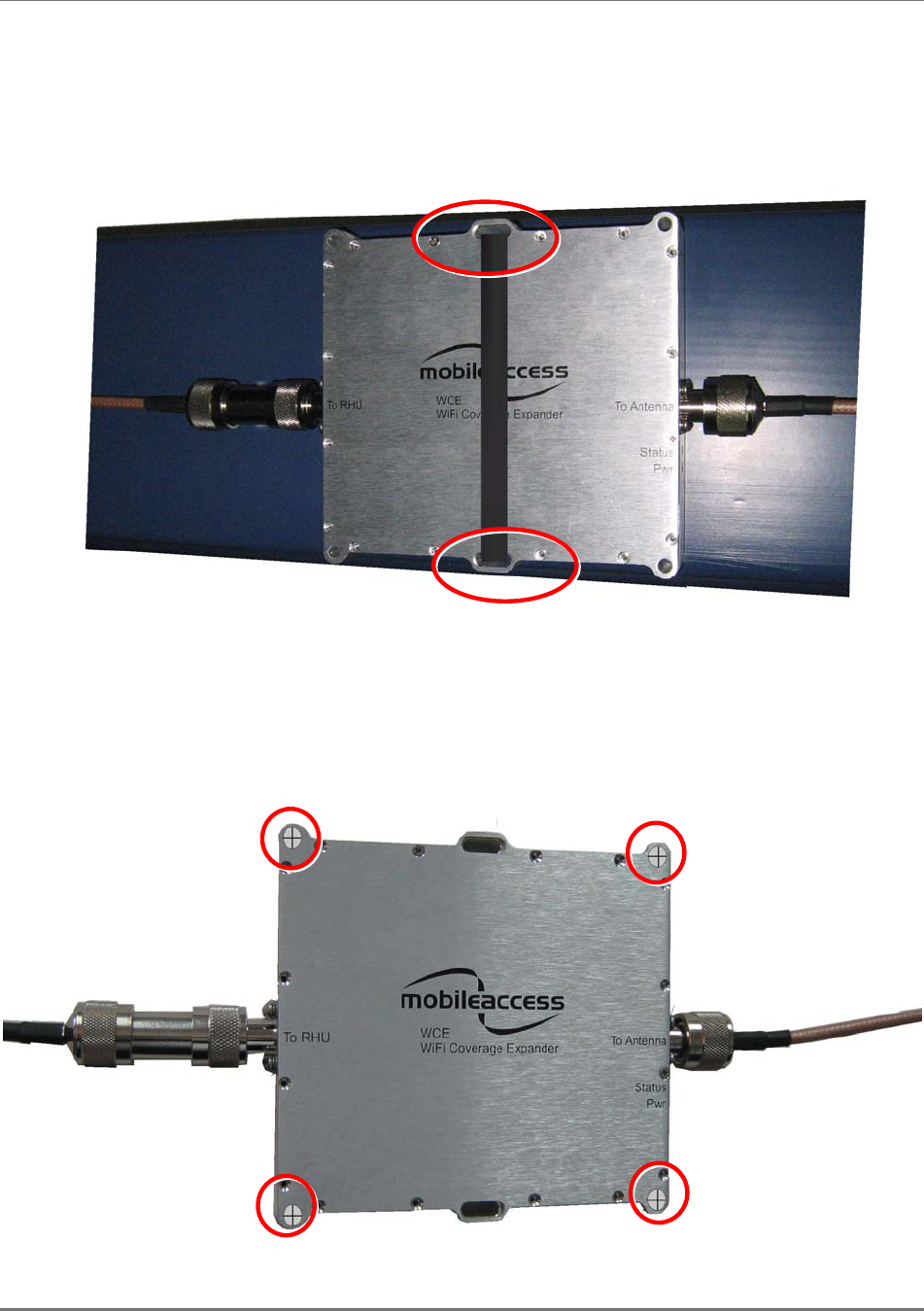
4.3.1 WCE Tie to Fixture Installation
Use the two mounting slots used to affix the unit to any available building infrastructure via a
wire-tie or tie-strap.
4.3.2 WCE Wall Mounted Using Four Screws
Secure the WCE using four standard drywall screws (3/16” in diameter).

Installation
MA-860 Installation and Configuration Guide 24
4.3.3 In Line with Coax Cables
WCE’s light design enables connecting it between the two coax cables without additional
support.
NOTE: The bending moment for ½” coax cable = 3lbs per foot.
4.4 860 WLAN Module Installation
MA 860 can be mounted in the following configurations:
•Standalone – mounted directly on the wall with four screws
•Mounted onto an MA 1000 RHU
•Mount as add-on to an MA 1000 RHU with an MA 1200 add-on unit
•Add-on to a MA 2000 system
To install the unit
•Depending on your installation mount the unit on the IDF or telecom Closet wall (standalone
installation) or assemble it onto the MA system (when converged with other MA systems)
•Record location and serial number of MA860 unit
Installation
MA-860 Installation and Configuration Guide 25
4.5 MA-860 Unit Installation and Connections
MobileAccess MA-860 is typically installed in the IDF or Telecom Closet of each floor to which
WLAN coverage is to be supported. The accessories, mounting and installation procedures vary
depending on the installation configuration.
4.5.1 Standalone Wall Mount Installation
Figure 4-1. MA-860 Standalone Installation Configuration
NOTE: It is recommended to record the location of the units and IP address according to the
MAC addresses on the sticker at the rear of the units near the Ethernet port.
Although it is not required for a stand-alone installation, it is recommended to set the supplied
cable 705102101 aside (usually used when MA-860 is installed in an add-on configuration).You
will need it if you want to upgrade your system to provide additional coverage options.
ATTENTION: Use SMA wrench for the SMA connectors, do not over tighten the
connectors.
Installation
MA-860 Installation and Configuration Guide 26
To install MA 860 wallmount standalone configuration
1. Mount the MA-860 on the wall using four screws. When mounting, consider the following:
•The type of screws used to mount the unit must suit the type of wall construction
(cement, bricks, etc.) so that the mount is secure.
•The position of the APs and required cable connections.
2. Connect the power (section 4.7).
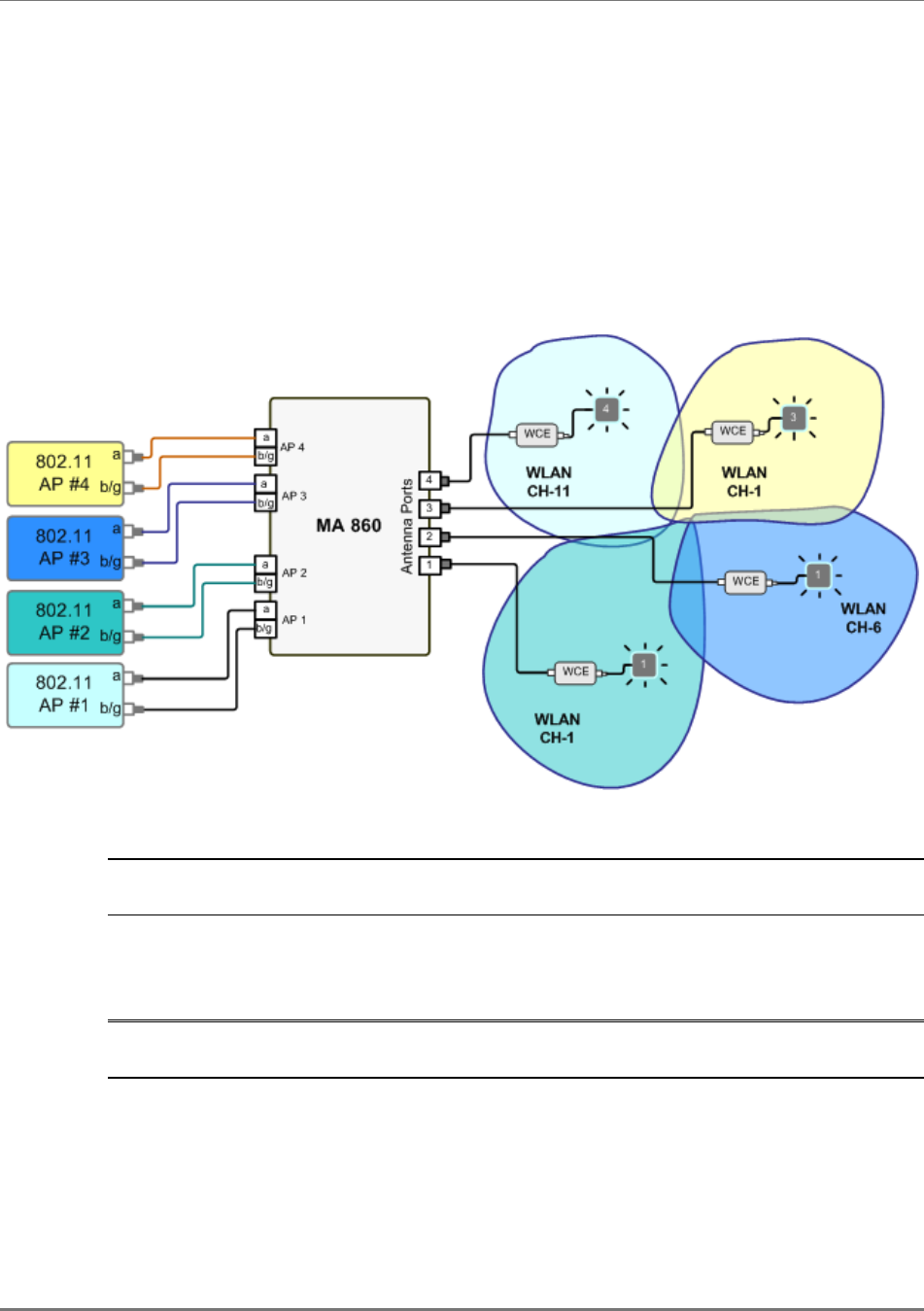
3. Connect the 802.11a/b/g Access Points to the corresponding ports on the MA-860 rear
panel.
Refer to section 1.3 for a description of the connections and distribution patterns.
NOTE: It is recommended to RESET the unit by removing and reinserting the power
connector on the front panel after connecting the APs.
4. Connect the coax antenna cables to the MA-860 unit antenna ports on the MA-860 front
panel according to the following instructions:
•Use 50 Ω, N-type male to male, 1/2” or 3/8” Plenum coax cables
•Max cable length (typically): 150’
5. Fit 50 ohm terminators on all unconnected SMA, AP and antenna ports.
6. Connect the RJ45 network connection to the MA-860 rear panel network port.
NOTE 1: It is recommended to record the location of the units and IP according to the MAC
addresses on the sticker at the rear of the units near the Ethernet port.
Installation
MA-860 Installation and Configuration Guide 27
4.5.2 Add-on to an MA 1000 System Installation
In this type of installation, the MA-860 and MA 1000 RHU are assembled together with a
bracket
between them.
NOTE: It is recommended to mount the MA-860 to the wall, and the MA 1000 on top of the MA
860 (with a bracket between them). However, if a previous MA 1000 RHU is present, you may
install the MA-860 on top of the existing MA 1000 RHU (with a bracket between them.)
Installation
MA-860 Installation and Configuration Guide 28
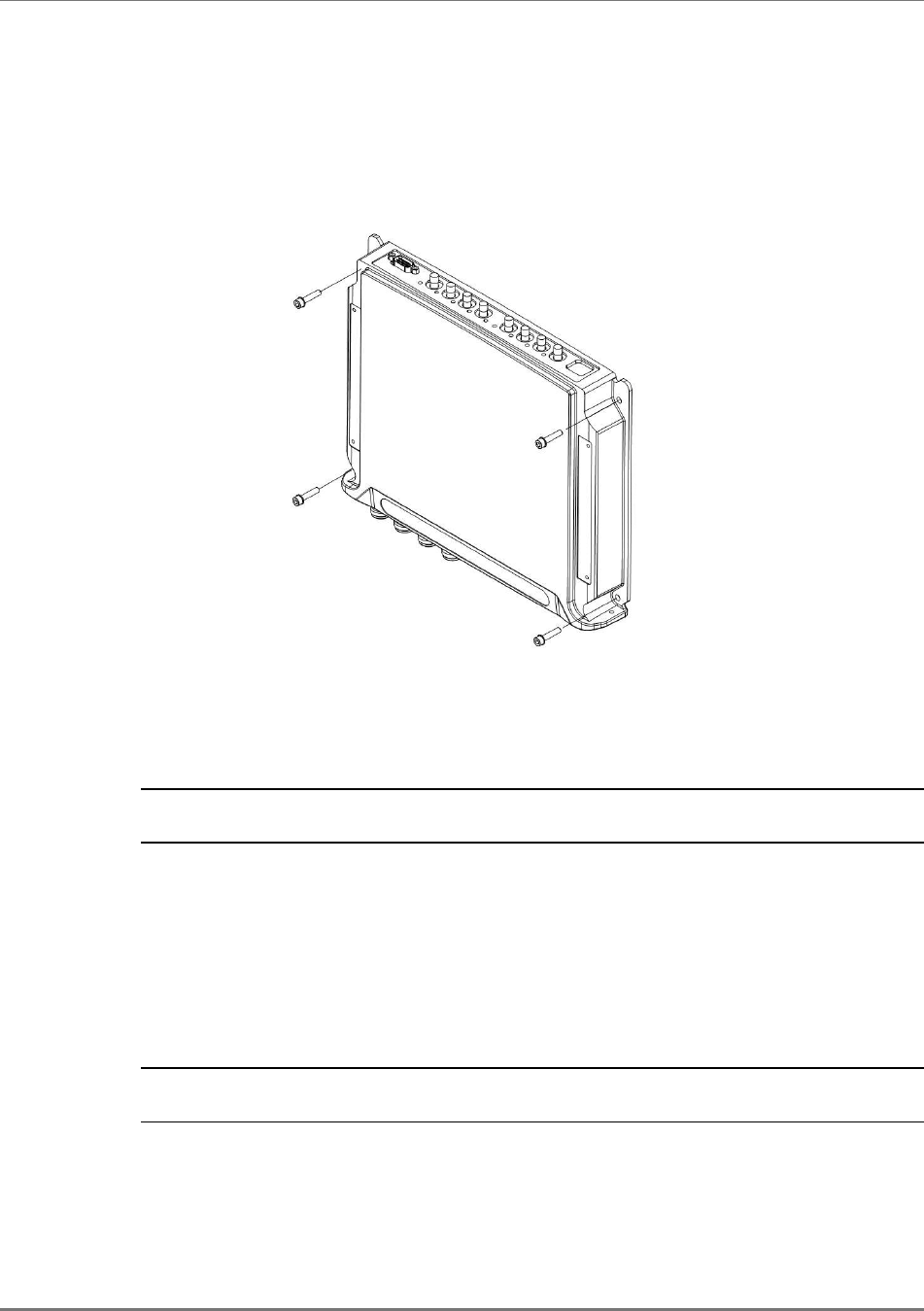
To assemble an RHU 1000 onto an MA 860
1. Assemble the supplied bracket to the top of the MA-860, where the notched side of the
bracket is towards the rear of the unit. Secure the bracket to the MA-860 unit using the four
supplied screws.
Figure 4-2. MA-860 and Bracket Assembly
2. Mount the MA-860 and bracket assembly to the wall. When mounting, consider the
following:
•The type of screws used to mount the unit must suit the type of wall construction
(cement, bricks, etc.) so that the mount is secure.
•The position of the APs and required cable connections.
3. Mount the MA 1000 RHU to the bracket using the four provided screws.
Two screws
Two screws
Installation
MA-860 Installation and Configuration Guide 29
4. For antenna sensing support (RHU 1000 version 3.1 and higher), connect between the
Control connectors at the rear of both units using cable 705102101.
NOTE: For antenna sensing support in RHU 1000 version 3.0 and lower, upgrade to a higher
version according to the MA 860 Upgrade Procedure Guide.
.
5. Connect the 802.11a/b/g Access Points to the corresponding ports on the MA-860 rear panel.
Refer to section 1.3 for a description of the connections and distribution patterns.
NOTE: It is recommended to RESET the unit by removing and reinserting the power
connector on the front panel after connecting the APs.
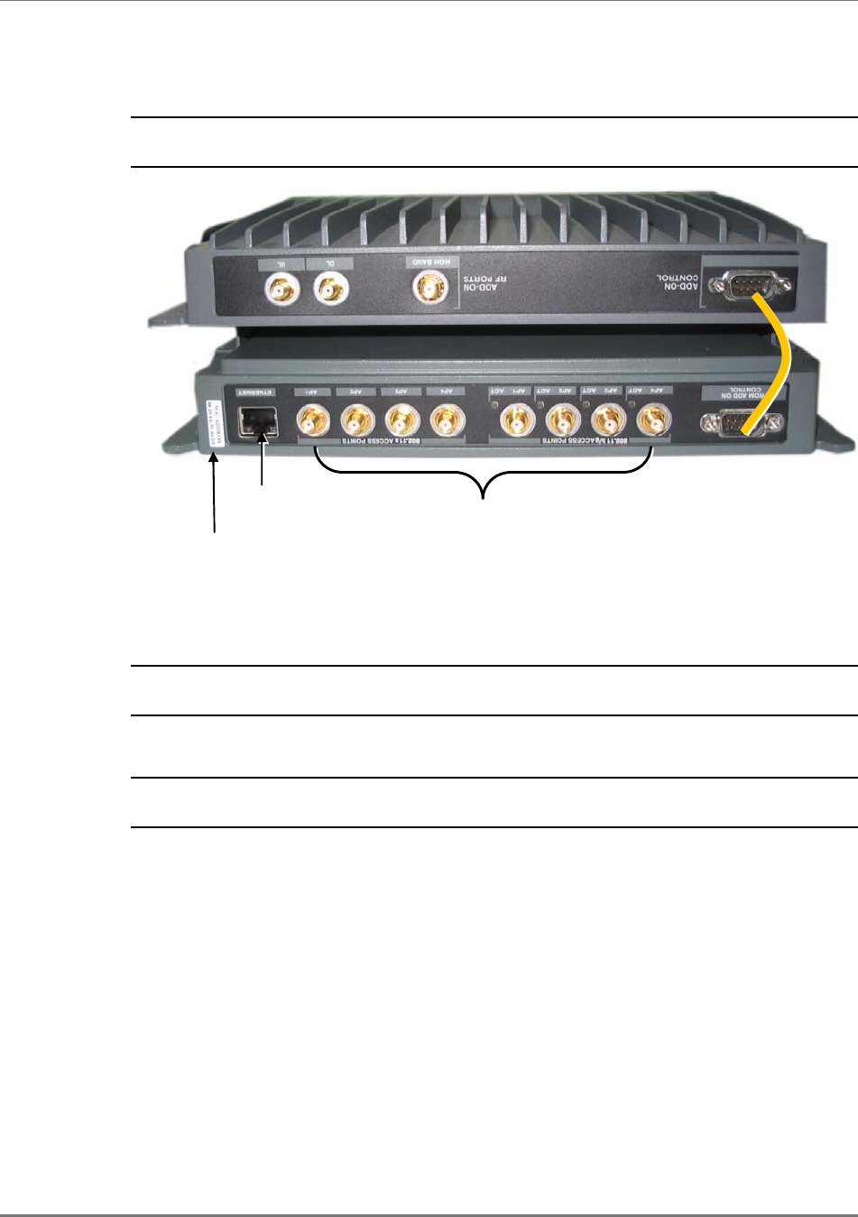
6. Connect the network connection to the MA-860 rear panel network port.
NOTE 1: It is recommended to record the location of the units according to the MAC
addresses on the sticker at the rear of the units near the Ethernet port.
705102101 connector
Ethernet
connection
MAC Address
M
A
-860
MA 1000 RHU
802.11b/g/a AP
connections
Installation
MA-860 Installation and Configuration Guide 30
5. Connect the MA 1000 antenna ports and the MA-860 Mobile Services ports using the
four SMA to N-type cables
supplied in the accessory kit
.
NOTE: Be sure the connectors are closed at a 45 degree angle so as not to place stress on
the cables.
6. Connect the power (section 4.7).
7. Connect the coax antenna cables to the MA-860 unit antenna ports on the MA-860 front
panel according to the following instructions:
•Use 50 Ω, N-type male to male, 1/2” or 3/8” Plenum coax cables
•Max cable length (typically): 150’
8. Fit 50 ohm terminators on all unconnected SMA, AP and antenna ports.
M
A
-860
MA 1000 RHU
Power
A
ntenna connections
N-type SMA
jumpers (included)
Installation
MA-860 Installation and Configuration Guide 31
4.5.3 Add-on to an MA 1000 with MA 1200
In this type of installation, the MA-860 and MA 1000/1200 assembly are separated by a bracket.
NOTE: It is recommended to mount the MA-860 to the wall, and the MA 10001200 assembly on
top of the MA 860 (with a bracket between them). However, if a previous MA 1000/1200
assembly exists, you may install the MA-860 on top of the existing assembly, (with a bracket
between them.)
To assemble an RHU 1000 onto MA 860
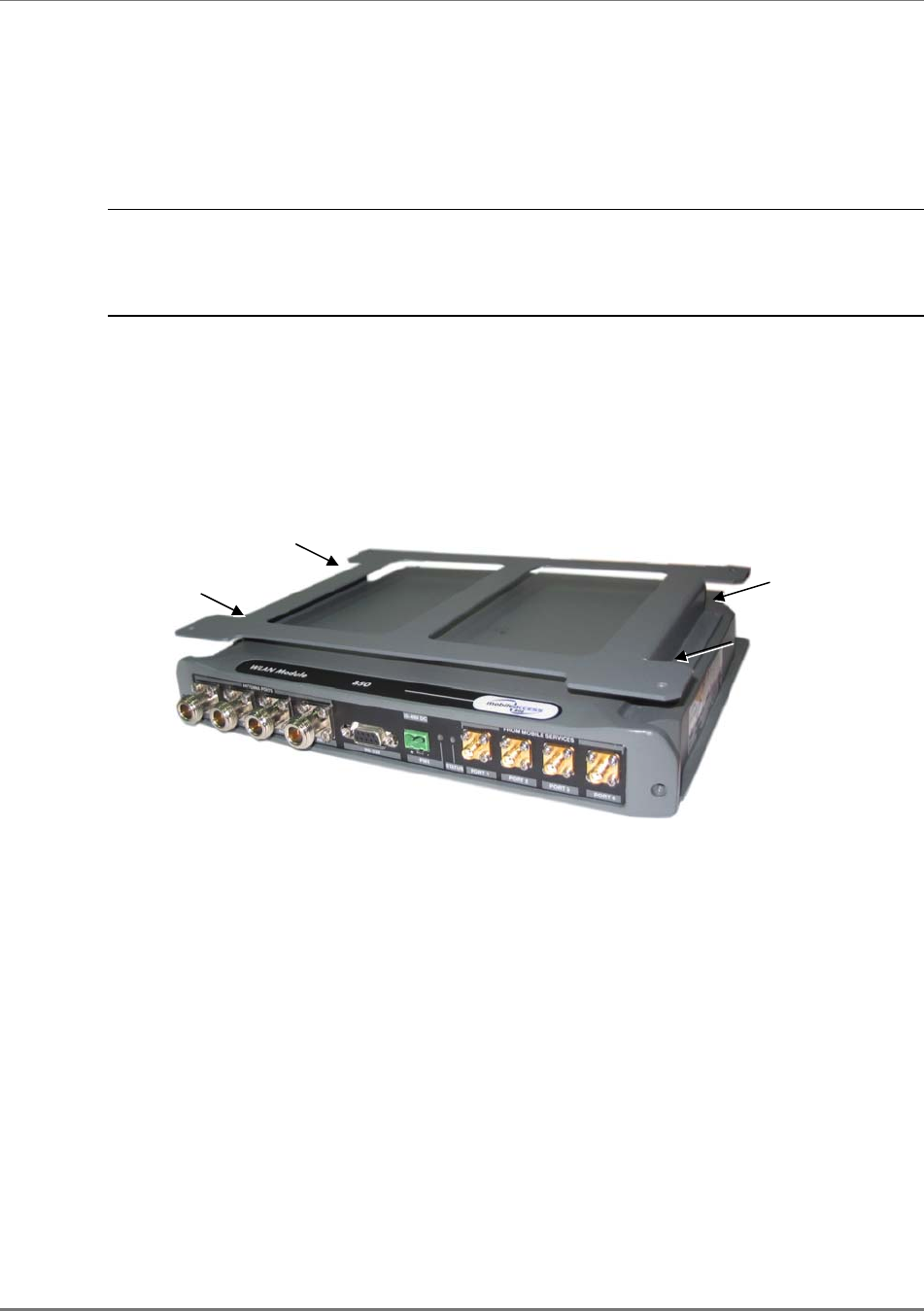
1. Assemble the supplied bracket to the top of the MA-860, where the notched side of the
bracket is towards the rear of the unit. Secure the bracket to the MA-860 unit using the four
supplied screws.
Figure 4-3. MA-860 and Bracket Assembly
Two screws
Two screws
Installation
MA-860 Installation and Configuration Guide 32
2. Mount the MA-860 and bracket assembly to the wall. When mounting, consider the
following:
•The type of screws used to mount the unit must suit the type of wall construction
(cement, bricks, etc.) so that the mount is secure.
•The position of the APs and required cable connections.
3. Assemble the MA 1000/1200 assembly to the MA-860 bracket.
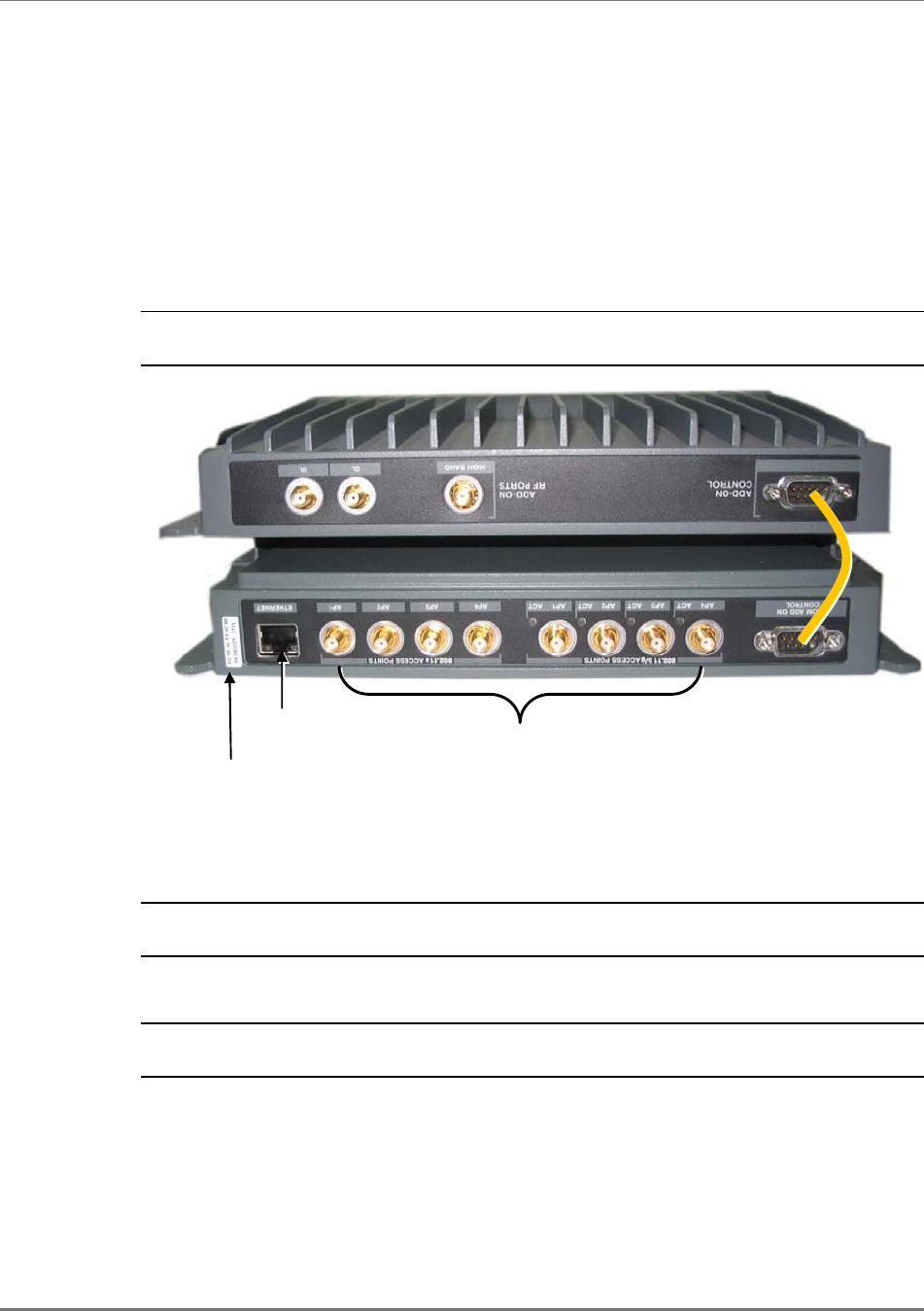
4. For antenna sensing support (RHU 1000 version 3.1 and higher), connect between the
Control connectors at the rear of both units using cable 705102101.
NOTE: For antenna sensing support in RHU 1000 version 3.0 and lower, upgrade to a higher
version according to the MA 860 Upgrade Procedure Guide.
.
5. Connect the 802.11a/b/g Access Points to the corresponding ports on the MA-860 rear
panel.
Refer to section 1.3 for a description of the connections and distribution patterns.
NOTE: It is recommended to RESET the unit by removing and reinserting the power
connector on the front panel after connecting the APs.
6. Connect the network connection to the MA-860 rear panel network port.
NOTE 1: It is recommended to record the location of the units according to the MAC
addresses on the sticker at the rear of the units near the Ethernet port.
705102101 connector
Ethernet
connection
MAC Address
M
A
-860
MA 1000 RHU
802.11b/g/a AP
connections
Installation
MA-860 Installation and Configuration Guide 33
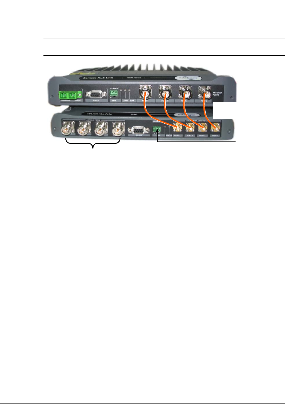
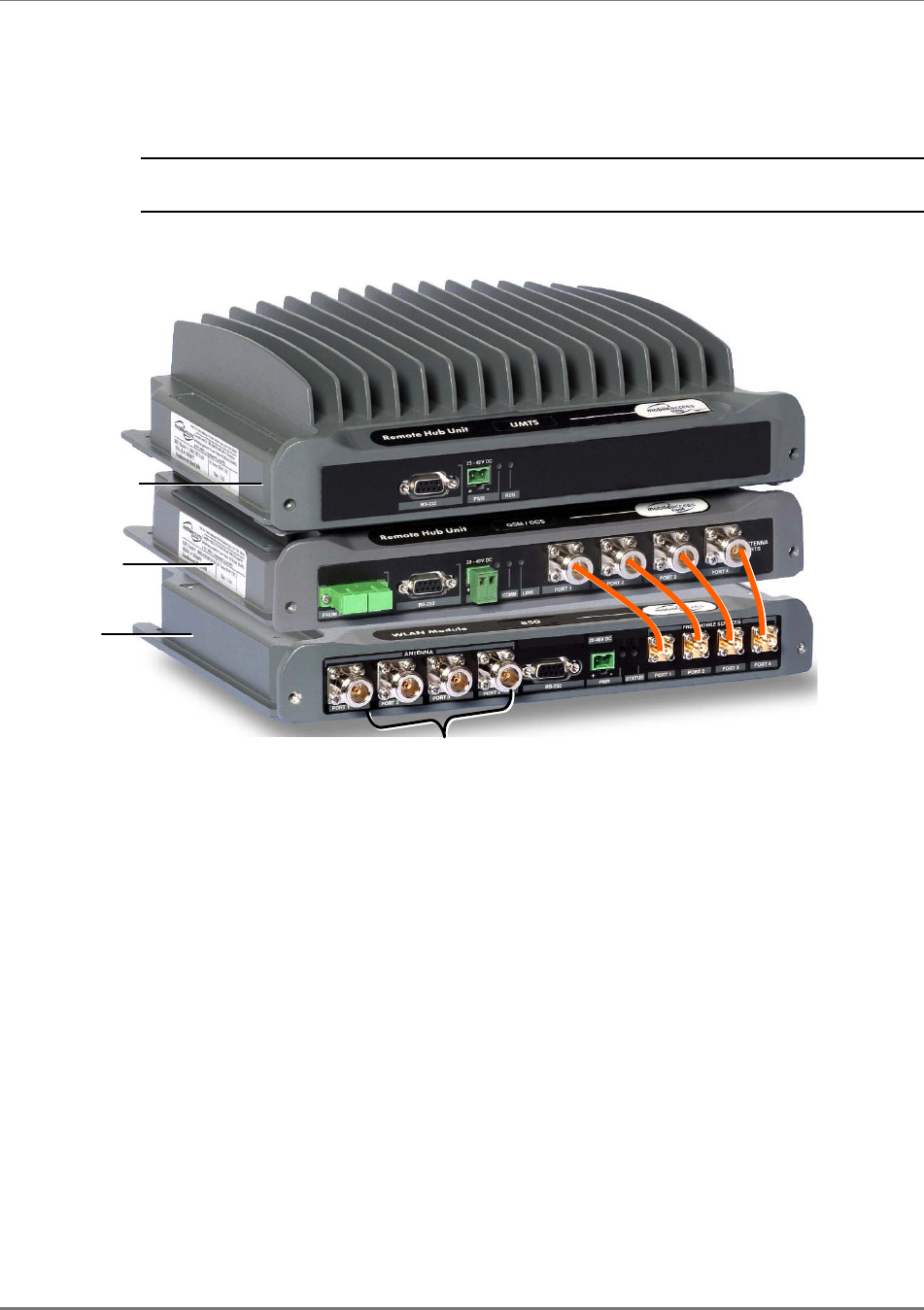
7. Connect the MA 1000 antenna ports and the MA-860 Mobile Services ports using the
four SMA to N-type cables
supplied in the accessory kit
.
NOTE: Be sure the connectors are closed at a 45 degree angle so as not to place stress on
the cables.
Figure 4-4. Connection of MA-860 and MA 1000 Service Ports
8. Connect the power (section 4.7).
9. Connect the coax antenna cables to the MA-860 unit antenna ports on the MA-860 front
panel according to the following instructions:
•Use 50 Ω, N-type male to male, 1/2” or 3/8” Plenum coax cables
•Max cable length (typically): 150’
10. Fit 50 ohm terminators on all unconnected SMA, AP and antenna ports.
MA 1200
M
A
-860
MA 1000
A
ntennas
N-type SMA jumpers
(included)
Installation
MA-860 Installation and Configuration Guide 34
4.5.4 Add-on to an MA 2000 System
MA-860 may be integrated into the MA 2000 system using one of the following installations:
•Installing it directly on the MA 2000 RC top panel (using the supplied plate);
•Mounting it on a rack (using the supplied plate);
•Wall-mount near the MA 2000 cabinet.
NOTE: The coax outputs of the cabinet are connected to the appropriate ports on the MA-860
and the antennas are connected directly to the MA-860 module.
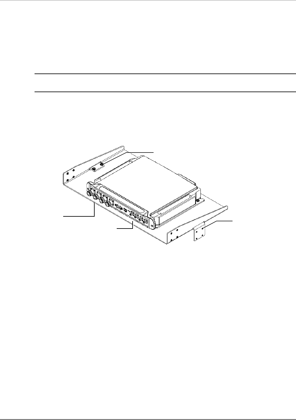
4.5.4.1 MA-860 RC 2000 Assembly
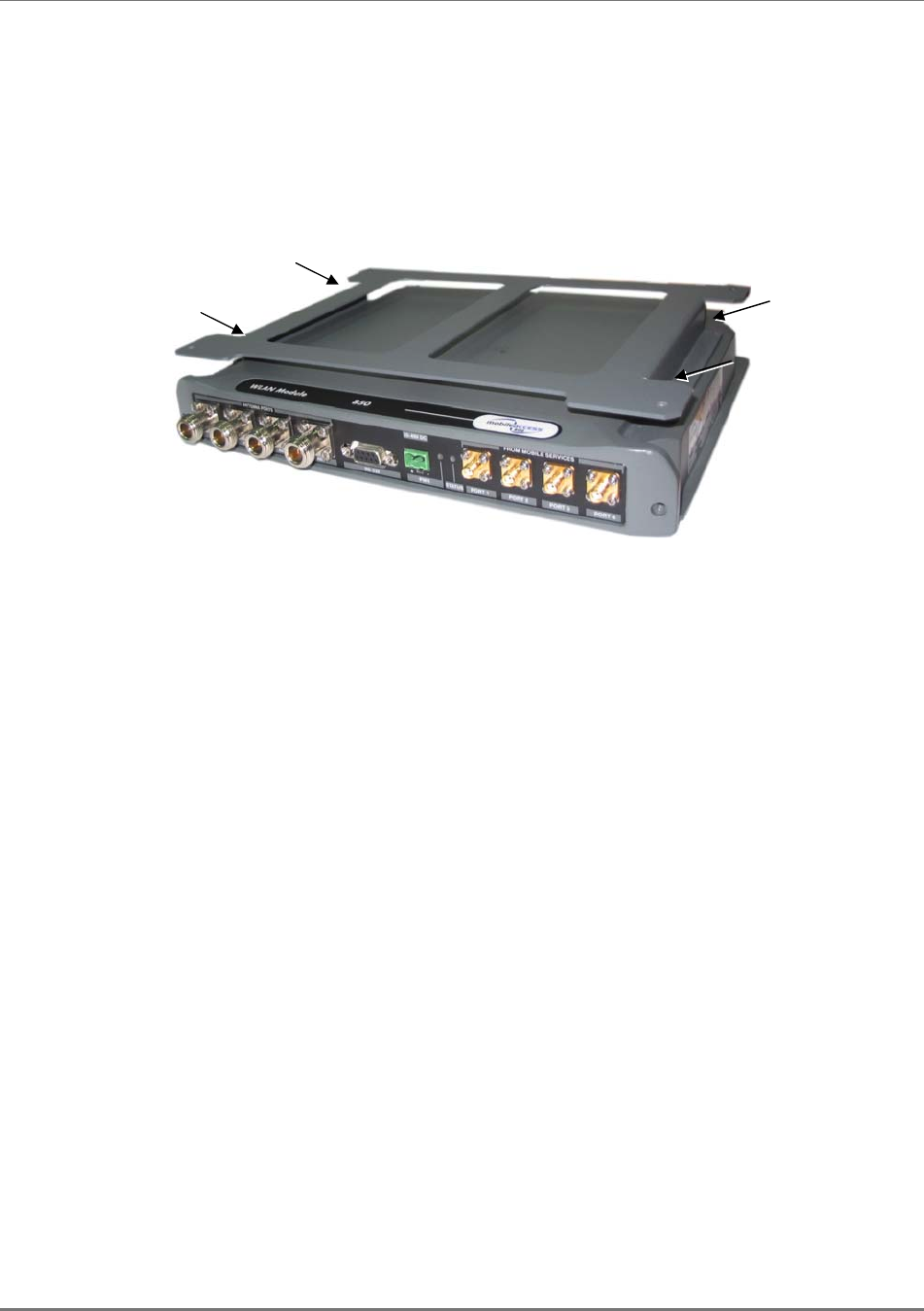
1. Assemble two side brackets to the plate sides as illustrated in Figure 4-5.
2. Assemble the MA-860 module to the supplied bracket using the four screws and washers as
illustrated below.
Figure 4-5. MA-860 Rack Installation
3. Assemble the plate to the MA 2000 RC by securing the brackets to the cabinet sides as
illustrated below.
Side bracket
assembly
Connections to Remote
Cabinet antenna ports
Connections to
antennas Side bracket
assembly
Installation
MA-860 Installation and Configuration Guide 35
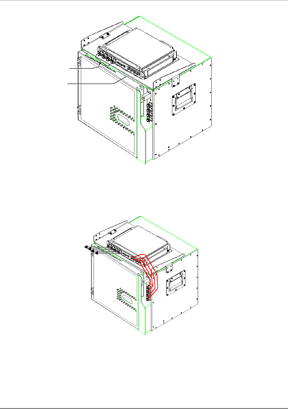
Figure 4-6. Illustration of MA-860 Mounted on MA 2000 RC
4. Connect the RC antenna ports to the MA-860 front panel port connectors as illustrated
below.
Figure 4-7. Illustration of RC Antenna port connections
5. Connect the antennas to the MA-860 antenna ports.
Connection to
Remote Cabinet
antenna
p
orts
Connection to
antennas
To antennas
Installation
MA-860 Installation and Configuration Guide 36
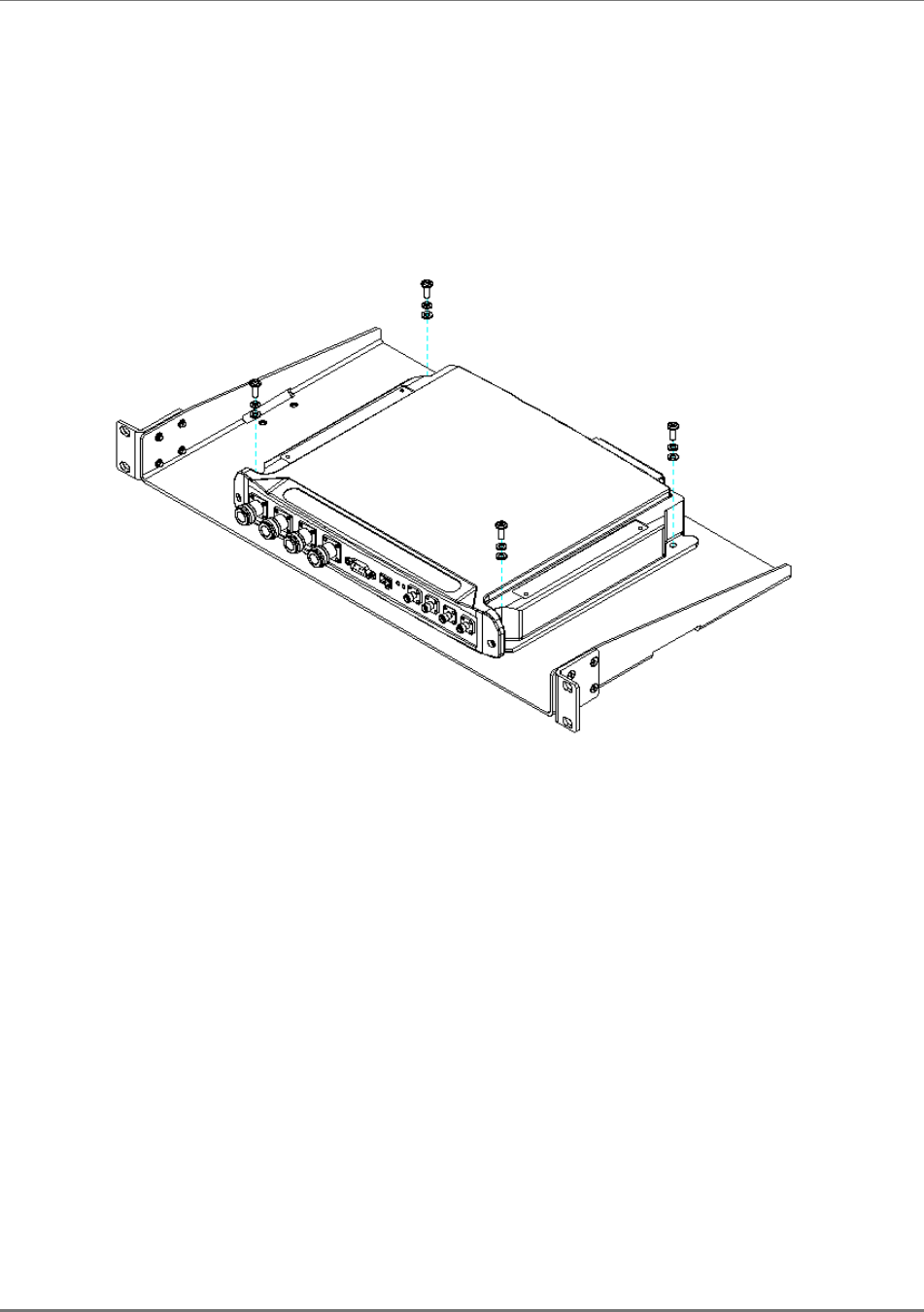
4.5.4.2 MA-860 Rack Mount
1. Assemble the side brackets as illustrated in Figure 4-5.
2. Assemble the MA-860 module to the supplied bracket using the four screws
and washers.
3. Mount the assembly in the rack using the side brackets.
Figure 4-8. MA-860 to Bracket Installation
4. Connect the RC antenna ports to the SMA connectors on the MA-860 front
panel.
5. Connect the antenna to the MA-860 antenna ports.
Installation
MA-860 Installation and Configuration Guide 37
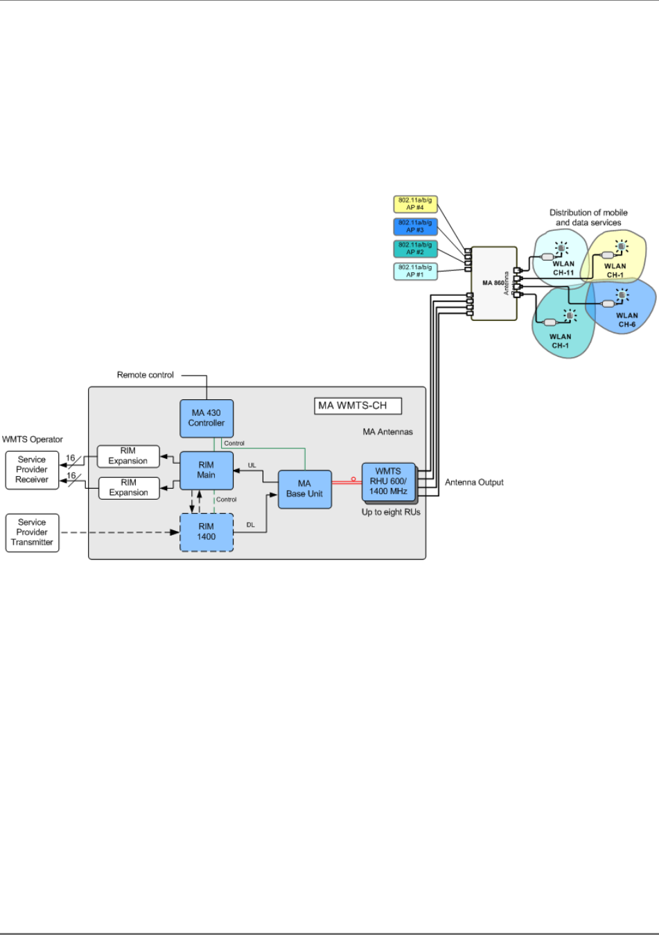
4.6 Add-on to MA WMTS-CH System
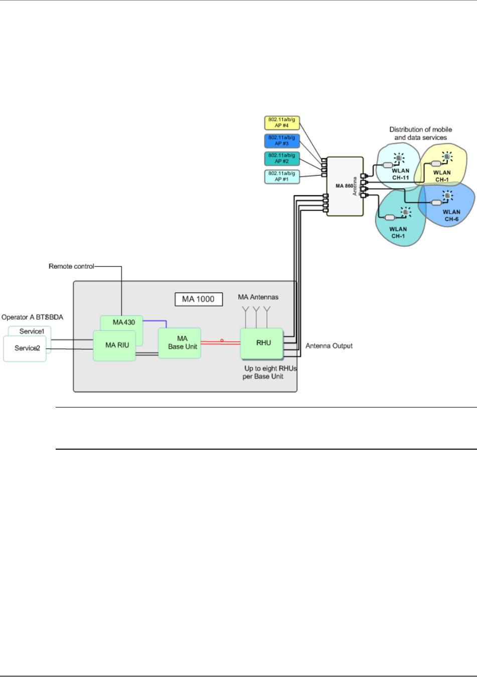
Figure-
4-9
shows the architecture of an installation supporting the indoor distribution of WMTS,
together with mobile and data services over a common coax and antenna infrastructure. Existing
or new MA 1000/2000 installations can be converged with WMTS installations through MA SMU.
Figure-
4-9 –Architecture of MA WMTS System Converged with MA 1000 System Services
Installation
MA-860 Installation and Configuration Guide 38
4.7 Connecting Power to the MA860
MA 860 is powered by a Main power supply mounted near the unit in the provided bracket. An
option for a redundant PS is also available.
In case a redundant power supply is installed with the unit, both (Main and Redundant) power
supplies are connected to the MA 860 power connector using the splitter cable.
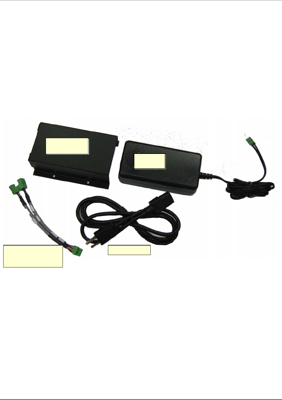
4.7.1 Power Supplies and Accessories
Shown below are the PS accessories (
redundant PS not shown
).
Main power
supply bracket
Splitter cable for
connecting Main and
redundant power supply
Main PS cable
Main PS
connector
Main power
supply