Corning Optical Communication QXC85P19L70A17 QX REMOTE UNIT User Manual
Corning Optical Communication Wireless QX REMOTE UNIT
User Manual
P/N: 709C0011101 REV: A00 Date: JANUARY2013
Corning
MobileAccess
MobileAccessQX
User Manual

Preface Material P/N: 709C0011101 Page II
Preface Material
RF Safety
To comply with FCC RF exposure compliance requirement, adhere to the following warnings:
Warning! Antennas used for this product must be fixed mounted on indoor permanent structures, providing a
separation distance of at least
75 cm from all persons during normal operation.
Warning! Each individual antenna used for this transmitter must be installed to provide a minimum separation
distance of 75 cm or more from all persons and must not be co-located with any other antenna for meeting RF
exposure requirements.
Warning! Antenna gain should not exceed 12.5 dBi.
Warning! The design of the antenna installation needs to be implemented in such a way so as to ensure RF
radiation safety levels and non-environmental pollution during operation.
ATTENTION
Compliance with RF safety requirements:
• MobileAccess products have no inherent
significant RF radiation
• The RF level on the downlink is very low at
the downlink ports. Therefore, there is no
dangerous RF radiation when the antenna
is not connected.
CAUTION
Use of controls, adjustments or performance of
procedures other than those specified herein may
result in hazardous radiation exposure.

Preface Material P/N: 709C0011101 Page III
Laser Safety Care of Fiber Optic Connectors
Fiber optic ports of the MobileAccessQX system
emit invisible laser radiation at the 1310/1550 nm
wavelength window.
The laser apertures /outputs are the green
SC/APC Bulkhead adapters located on the front
panel of the equipment.
External optical power is less than 10 mW,
Internal optical power is less than 500 mW.
To avoid eye injury never look directly into the
optical ports, patchcords or optical cables. Do not
stare into beam or view directly with optical
instruments. Always assume that optical outputs
are on.
Only technicians familiar with fiber optic safety
practices and procedures should perform optical
fiber connections and disconnections of
MobileAccessQX devices and the associated
cables.
MobileAccessQX has been tested and certified as
a Class 1 Laser product to IEC/EN 60825-1
(2007). It also meets the requirements for a
Hazard Level 1 laser product to IEC/EN 60825-2:
2004 to the same degree.
MobileAccessQX complies with 21 CFR 1040.10
and 1040.11 except for deviations pursuant to
Laser Notice NO. 50 (2007).
MobileAccessQX employs a Class 3B laser and
therefore the following label is affixed inside the
unit adjacent to the laser:
Do not remove the protective covers on the fiber
optic connectors until a connection is ready to be
made. Do not leave connectors uncovered when
not connected.
The tip of the fiber optic connector should not
come into contact with any object or dust.
Refer to the cleaning procedure for information
on the cleaning of the fiber tip.

Standards and Certification P/N: 709C0011101 Page IV
Standards and Certification
Corning MobileAccess products have met the approvals of the following certifying organizations:
Company Certification
ISO ISO 9001: 2000 and ISO 13485: 2003
Product Certifications
US Radio Equipment and Systems:
• FCC 47 CFR Part 22 – for CELL Frequency Band
• FCC 47 CFR Part 24 – for PCS Frequency Band
• FCC 47 CFR Part 27 – for 700 LTE and AWS Frequency Bands
EMC
• FCC 47 CFR Part 15 Subpart B
Note: This equipment has been tested and found to comply with the limits for a Class B digital device,
pursuant to Part 15 of the FCC Rules. These limits are designed to provide reasonable protection
against harmful interference in a residential installation. This equipment generates, uses and can
radiate radio frequency energy and, if not installed and used in accordance with the instructions, may
cause harmful interference to radio or television reception, which can be determined by turning the
equipment off and on, the user is encouraged to try to correct the interference by one or more of the
following measures:
- Reorient or relocate the receiving antenna.
- Increase the separation between the equipment and receiver.
-Connect the equipment into an outlet on a circuit different from that to which the receiver is
connected.
-Consult the dealer or an experienced radio/TV technician for help.
Warning! Changes or modifications to this equipment not expressly approved by Corning
MobileAccess could void the user’s authority to operate the equipment.
Europe Radio Equipment and Systems
EN 301 502 – for GSM / EGSM Frequency Bands
About this Guide and Other
Relevant Documentation P/N: 709C0011101 Page V
EN 300 328 – for WLAN 802.11b/g 2.4GHz Frequency Band
EN 301 893 – for WLAN 802.11a 5GHz Frequency Band
EMC
EN 301 489
Safety EN 60950UL 60950
CAN/CSA-C22.2 No.60950
UL 2043
Laser
Safety CDRH 21 CFR 1040.10, 1040.11 (Except for deviations per notice No.50, July 26, 2001)
IEC 60825-1, Amendment 2 (January 2001)
EN 60825-1
About this Guide and Other Relevant Documentation
This user guide describes how to perform the physical installation of the MA2000 systems. The installation
procedures of other units (e.g. RIU, SC-450) relevant to the system are detailed in their user manuals (see
Additional Relevant Documentation below).
Additional Relevant Documents
The following documents are required if the corresponding units are included in your system.
Document Name
RIU Installation and Configuration Guide
System Controller (SC-450) User Manual
MobileAccessQX Datasheet
MA Software Version Update Tool

List of Acronyms P/N: 709C0011101 Page VI
List of Acronyms
BDA Bi-Directional Amplifier
BTS Base Transceiver Station
BTSC Base Transceiver Station Conditioner
BU Base Unit
DL Downlink
RU Remote (Hub )Unit
RIU Radio Interface Unit
RBS Radio Base Station
UL Uplink

Table of Contents I P/N: 709C0011101 I Page VII
Table of Contents
Preface Material ........................................................................................................................ II
RF Safety .......................................................................................................................................... II
Laser Safety ..................................................................................................................................... III
Care of Fiber Optic Connectors .......................................................................................................... III
Standards and Certification ................................................................................................... IV
Company Certification ....................................................................................................................... IV
Product Certifications ........................................................................................................................ IV
About this Guide and Other Relevant Documentation .......................................................... V
List of Acronyms ..................................................................................................................... VI
Table of Contents ................................................................................................................... VII
1 Introduction ........................................................................................................................ 1
1.1 Key Features and Capabilities ....................................................................................................... 1
1.2 System Architecture ..................................................................................................................... 2
1.3 QX Interfaces and Internal Modules .............................................................................................. 4
1.3.1 QX Interfaces ..................................................................................................................... 4
1.3.2 QX Main Internal Modules ................................................................................................... 6
1.4 SCU-F Interfaces .......................................................................................................................... 7
2 Installation Guidelines ....................................................................................................... 8
2.1 Infrastructure Preparation ............................................................................................................ 8
2.2 Installation Requirements ............................................................................................................. 8
2.3 Coaxial Cable Connections ............................................................................................................ 8
2.3.1 General Cable Installation Procedures .................................................................................. 8
2.3.2 RF Rules ............................................................................................................................ 9
2.3.3 Coax Cable Lengths and Losses ........................................................................................... 9
2.4 Fiber Optic Rules ....................................................................................................................... 10
2.5 Power Consumption, Connections and Power Supplies ................................................................. 11
2.5.1 Power Safety Instructions ................................................................................................. 11
2.5.2 Types of Power Supplies ................................................................................................... 11
2.6 Installation Conventions ............................................................................................................. 11
3 System Installation .......................................................................................................... 12
3.1 Overview of Physical Installation ................................................................................................. 12
3.2 Unpacking and Inspection .......................................................................................................... 12

Table of Contents I P/N: 709C0011101I Page VIII
3.3 Inserting an RHU/AO Module in to QX Chassis ............................................................................. 14
3.4 Mounting ................................................................................................................................... 16
3.4.1 Rack Mount Installations ................................................................................................... 16
3.4.1.1 Plan the rack installation ....................................................................................... 16
3.4.1.2 Rack Installation Safety Instructions ...................................................................... 17
3.4.1.3 Mounting QX Unit in 19-IN Rack ............................................................................ 17
3.4.1.4 Mounting SCU-F Unit ............................................................................................ 17
3.4.2 Wall Mount Installation ..................................................................................................... 18
3.4.2.1 QX Horizontal Wall Mount Installation .................................................................... 19
3.4.2.2 QX Vertical Wall Mount Installation ........................................................................ 21
3.5 Connections ............................................................................................................................... 24
3.5.1 QX Fiber Optic Connections ............................................................................................... 24
3.5.1.1 MIMO Configurations ............................................................................................ 25
3.5.2 RF Connections ................................................................................................................ 26
3.5.2.1 QX RF and Antenna Monitoring Connections .......................................................... 26
3.5.2.2 RF MIMO Connections to SCU-F ............................................................................ 28
3.5.2.3 Daisy Chaining the AMU modules of Multiple QX Units to a Single SCU-F ................. 29
3.5.2.4 SCU-F to Broadband Antenna Connections ............................................................. 30
3.5.3 Grounding the QX Unit ...................................................................................................... 30
3.5.4 Power Connections ........................................................................................................... 31
3.6 Verifying Normal Operation ........................................................................................................ 32
4 Maintenance ..................................................................................................................... 34
4.1 Replacing an RHU/AO Module ..................................................................................................... 34
4.2 Replacing Fan Module ................................................................................................................ 36
5 Appendix A: System Specifications ............................................................................... 38
RF Parameters .................................................................................................................................. 38
Supported Services .................................................................................................................... 38
RF Parameters per Service at Antenna Port of Four Port Service Combiner Unit (SCU-F) ................. 39
Absolute Maximum Rating .......................................................................................................... 40
Optical Specifications ........................................................................................................................ 40
Environmental Specifications.............................................................................................................. 40
Standards and Approvals ................................................................................................................... 41
System Component Specifications ...................................................................................................... 42
Quad-Service Package (QX) ........................................................................................................ 42
Four - Port Service Combiner Unit (SCU-F) .................................................................................. 42
6 Appendix B: Ordering Information .................................................................................. 43
Introduction I P/N: 709C0011101I Page 1
1 Introduction
MobileAccess2000 QX (QX) is a member of
the MobileAccess2000 family. It is a compact,
modular, cellular indoor coverage remote unit
supporting up to four services (currently,
CELL/PCS, LTE and AWS).
All services are received from the head-end,
over a single optic fiber and reconverted to
RF for convergence and distribution over a
common DAS antenna infrastructure.
Service support can be quickly added as
needed by inserting card like modules into
the chassis without any downtime or
additional cabling. In addition, two QX units
can b
e cascaded to provide various
combinations of SISO and MIMO services
distributed over the same antenna
infrastructure.
MA2000 QX is managed by opening a Web
session to the SC-450 Controller.
MA2000 QX operates along with an SCU-F
unit, which converges the services from one
or more MA2000 QX units and provides the
interface to the DAS infrastructure. Both QX
and SCU-F are described in this manual.
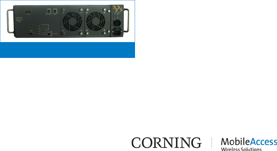
MobileAccessQX
Figure 1-1
1.1 Key Features and
Capabilities
The following benefits are achieved with
the QX platform:
• Multi-Service Platform - Supports up to
four services. Currently supported:
CELL, PCS, AWS, 700 MHz LTE
• Multi-Operator Optimized Platform -
Services from a number of operators
can be supported by the same chassis
or by different units and distributed
over a common DAS antenna
infrastructure.
• Optic Fiber savings - All services routed
to a QX unit are routed over a single
optic fiber
• Modular Design -
Seamless service
upgrades – simply add a card in
the
QX (and the parallel service
conditioning module at the head end)
• Scalable MIMO Upgrades - Upgrade any
or all services from SISO to MIMO by
cascading another QX unit
• Small Footprint - 3 U height rack
• Simple maintenance -
All connections
and monitoring LEDs located on front
panel, Modular, hot-
swap, field
replaceable service modules, including
fan modules
• Web Management - Web management
via the SC-450 controller
System Architecture I P/N 709C011101 I Page 2
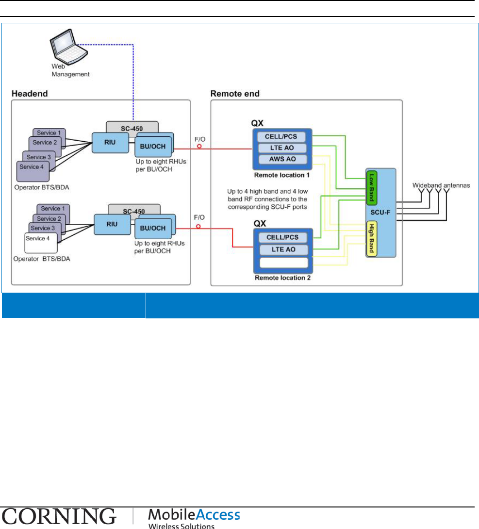
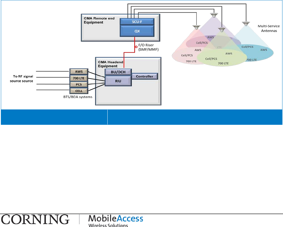
1.2 System Architecture
The QX and SCU-F are located at the floor level remote end. QX receives RF over optic service
signals from the head end, reconverts the signals to RF over copper, adjusts them to the
required level and outputs each service to dedicated interfaces. The signals are combined by
the SCU-F (along with services from other QX units) and distributed over a common DAS
(Distributed Antenna System) infrastructure.
In the uplink, cellular service signals received at the DAS are separated by the SCU-F and
routed to their dedicated QX ports. The signals are then converted to optic and forwarded to
the head-end for reconversion to RF and distribution to the relevant BTS or BDA systems.
Note: 3rd party equipment is sold separately (i.e. cabling, antennas).
QX Architecture Diagram Figure 1-2
Headend:
At the headend CMA elements provide interface to the wireless service provider’s network,
condition the signals and convert them to optical signals for transportation over fiber optics
towards the remote ends.
• Radio Interface Unit (RIU) - the RIU conditions and custom tunes the RF Downlink (DL)
signals from an operator’s signal source (BTS or BDA) to ensure a constant RF level. In the
Uplink (UL), the signal (at the required level) is routed back to the operator’s signal source.
System Architecture I P/N 709C011101 I Page 3
• RF to Optic converter unit – this can either be a Base Unit (BU) or an Optical Control
Head End Unit (OCH), where the OCH is QX model specific. These are wideband units that
convert the RF Downlink (DL) signals from the RIU into optical signals for routing over
single or multi-mode fiber optic cabling (SMF/MMF) to/from the QX units located at the
remote locations up to 2Km away.
• System Controller (SC-450) - the system controller enables centralized remote
management and control of MobileAccess elements. This unit connects directly to the RIU
and BU and/or OCH and allows management of these as well as their hosted elements (e.g.
QX) via a controller Web session.
Remote End:
At the remote end, the optical signal is reconverted to RF, filtered, amplified to the appropriate
level, combined with other signals and distributed over the broadband antenna infrastructure.
The QX unit is installed, along with the Four Port Service Combiner Unit (SCU-F). The QX
system remote end consists of the following elements:
• QX - each QX unit provides coverage for four RF services (e.g. CELL, PCS, 700LTE and
AWS) via two types of service dedicated internal modules (RHU and AO). Each of these
modules is monitored via the Controller as an independent unit.
• Service Combiner Unit (SCU-F): a passive module that combines and distributes the UL
and DL signals from one or more QX units to (up to) four broadband antennas.
QX Solution System Architecture Figure 1-3
QX Interfaces and Internal Modules I P/N 709C011101 I Page 4
1.3 QX Interfaces and Internal Modules
1.3.1 QX Interfaces
This section provides a full, detailed description of the QX unit and relevant interface
connections (Table 1-2) and LED indicators.
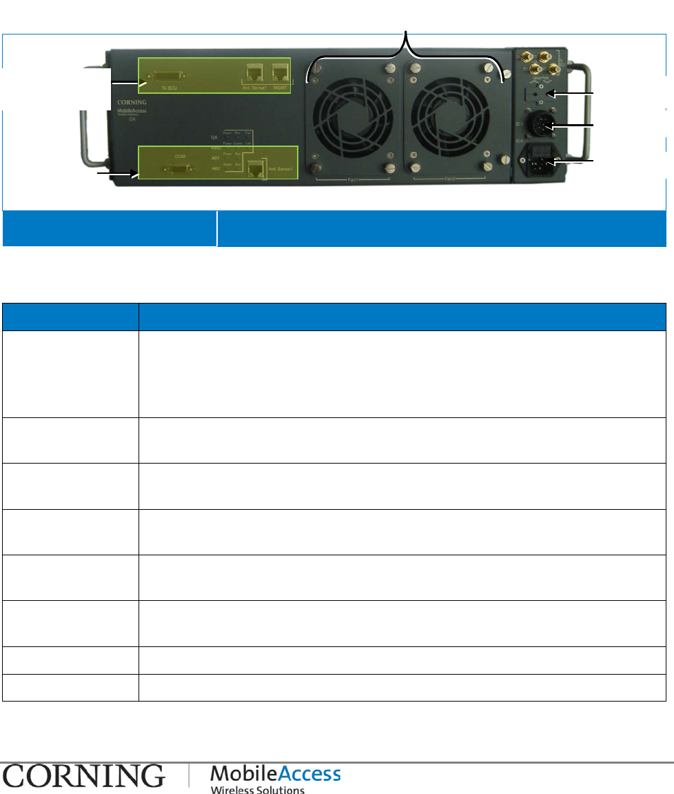
MobileAccessQX Front Panel Figure 1-4
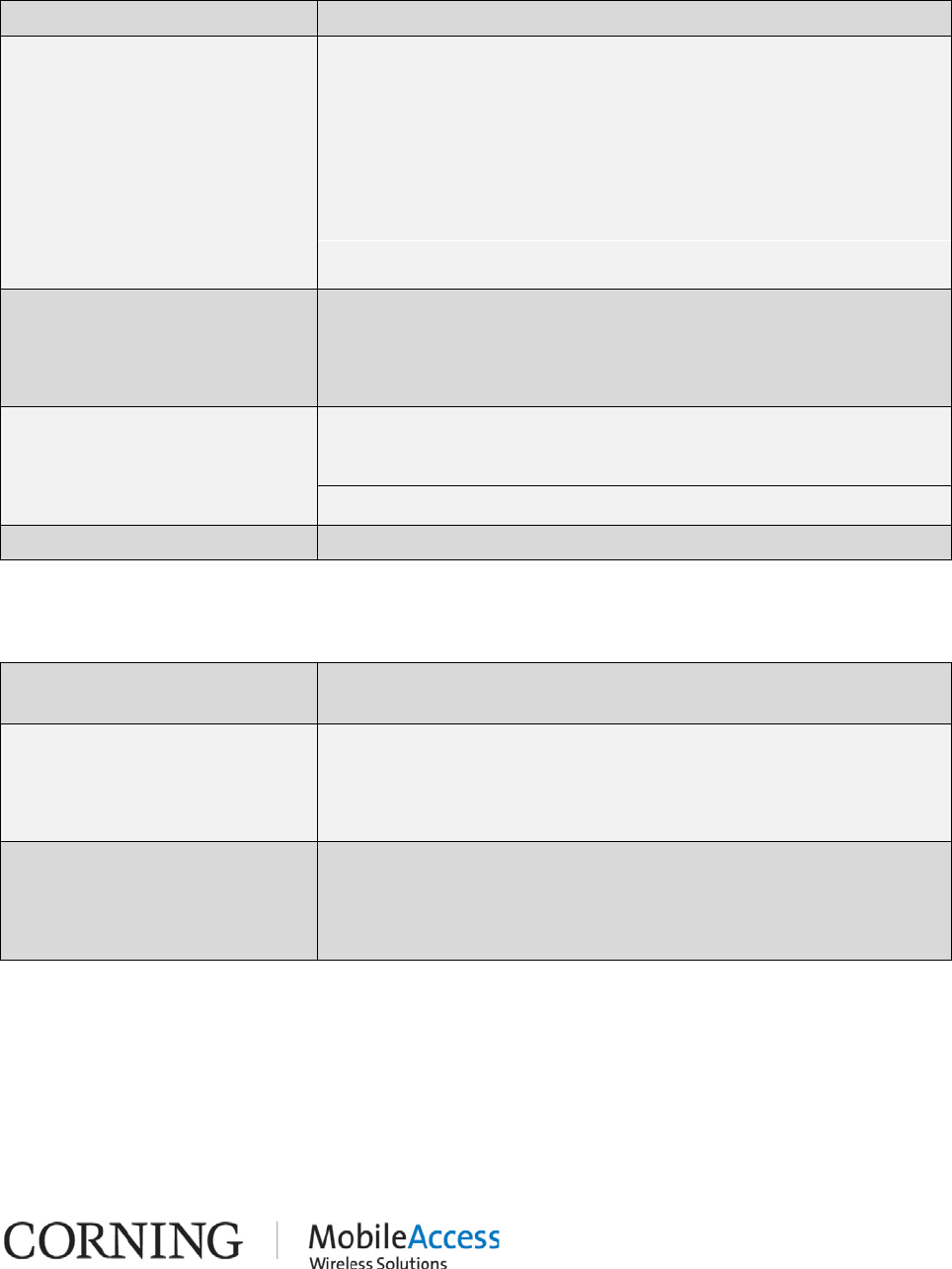
Table 1-1. QX Front Panel Interfaces
Interface Description
DB-15 AMU (Antenna Monitoring Unit) port. Connect to parallel port on SCU-F.
Note that only one QX unit port can be connected to the parallel SCU-F
port. For installations with more than one QX, cascade QX AMU ports
using IN/OUT ports.
IN/OUT AMU cascading ports. Use in case there are more than one QX units
connected to the SCU-F.
DB-9 RS232 serial connection (D-Type 9); Serves as AMU console port for
service personnel
Console Connect to network for AMU SW upgrade – for tech support personnel
only
Service specific
QMA connectors Used for connecting to corresponding SCU-
F High band and Low Band
QMA connectors.
Optic Port Slot Slot used to guide the optic fiber to the RHU module fiber optic SC/APC
port inside the chassis.
AC In Local AC power connection: 100-240VAC (use either AC or DC)
DC In Remote DC power connection: 25 to 48VDC (use either AC or DC)
AMU connection
ports
AMU service
ports
Fan modules
AC power
DC power
Optic port
slot
QX Interfaces and Internal Modules I P/N 709C011101 I Page 5
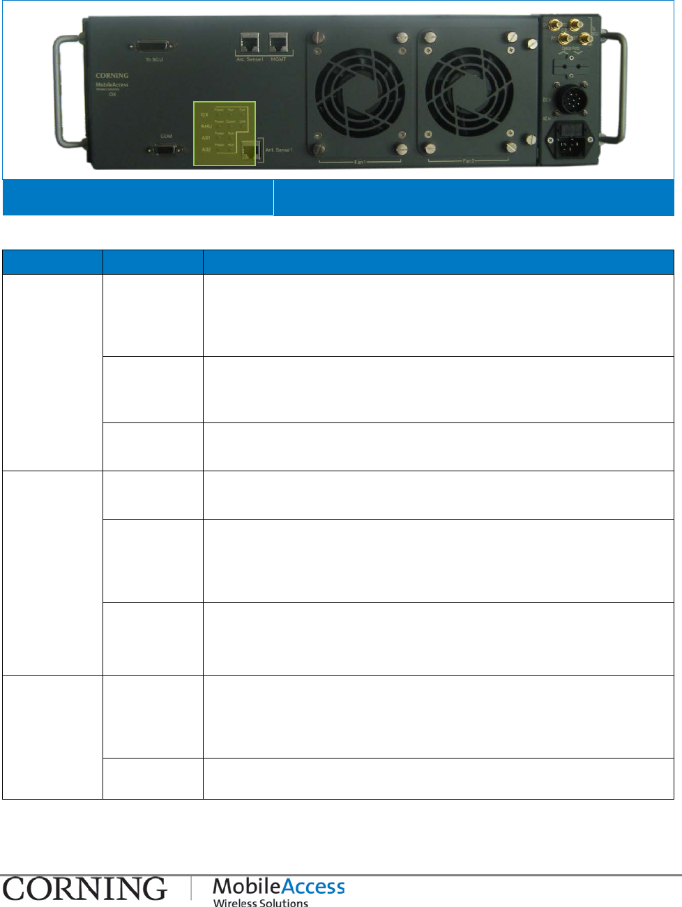
The QX front panel supports three groups of LEDs: system level, for the RHU and for each Add-
on unit.
MobileAccessQX Front Panel Figure 1-5
Table 1-2: LEDs Descriptions:
Module LED Description
QX (system
level) Power Steady Green: Required power is supplied to AMU module
of QX chassis
Off: No power supplied to AMU module of QX
chassis
Run Steady Green: AMU module SW initialized
Blinking Green: AMU module SW is initializing
(blinks for
the duration of approx. 1 minute)
Fan Steady Green: Fan status normal
Blinking Green: Faulty fan, alarm triggered
RHU Power Steady Green: Power input detected for RHU module
Off: No power detected for RHU module
Comm Blinking Green: Active communication detected –
connected and discovered by the BU/OCH
Steady Slow Blink: Faulty communication link -
no external
communication is received
Link Steady Green: Normal optical link level from BU/OCH-QX
Blinking Green: Low optical link level from BU/OCH-QX
Off: No optical link is present
AO1/AO2 Power Steady Green: Power input detected for first/second Add-
On unit
Off: No power detected for first/second Add-On
unit
Run Blinking Green: Indicates that the Add-On module is in
normal operating mode.
Table 1-3: LED Descriptions

QX Interfaces and Internal Modules I P/N 709C011101 I Page 6
1.3.2 QX Main Internal Modules
The QX main components consist of the following internal modules:
• Remote Hub Unit (RHU) – service specific unit, supports two voice services, converts the
optical signals received from the BU/OCH to RF signals (and vice versa) and routes them to
the coax antenna infrastructure (via the Four Port Service Combiner Unit – SCU-F).
• Add-On (AO) – adds an additional voice service to the host RHU (QX includes two AO
modules hosted by the RHU)
Note: The voice services are combined by the connected Service Combiner Unit (SCU).
• Antenna Monitoring Unit (AMU) – digital unit that enables antenna monitoring and relay
messaging of the following information:
• Antenna status
• Fans status
• Fans control
• AMU/QX alarms.
The AMU is connected to the SCU. The AMU modules of a number of QX units can be daisy
chained to a single SCU-F (see section 3.5.2.1).
• Fan Module – two extractable fans, simple to maintain and replace (see section 4.2).
SCU-F Interfaces I P/N 709C011101 I Page 7
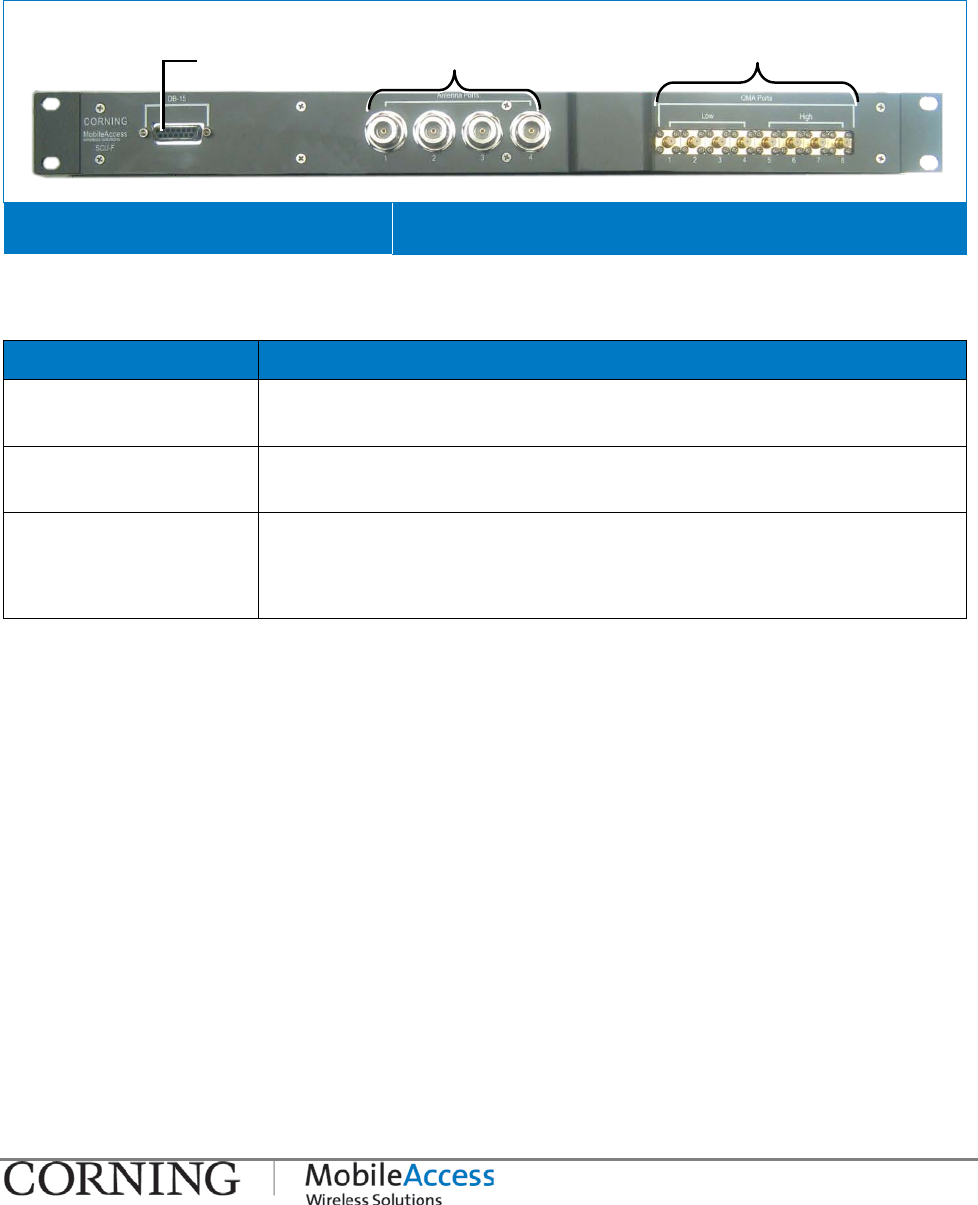
1.4 SCU-F Interfaces
The SCU-F is a passive unit which interfaces to the QX RF service ports and internal AMU
module and to the DAS infrastructure. All of the interfaces are located on the front panel
(shown in Figure 1-6).
SCU-F Front Panel Figure 1-6
Table 1-4. SCU-F Front Panel Interfaces
Interface Description
DB-15 DB-15 port used to connect the SCU-F to the QX DB-
15 port
(internal AMU module port)
Antenna Ports N-Type RF antenna ports used to
connect to the broadband
antenna infrastructure
QMA Ports (Low/High) QMA type RF ports used to connect to the QX service ports:
Low: Ports 1-4 support low band service connections from the QX
High: Ports 5-8 support high band service connections from the QX
DB-15 port to
QX DB-15 port
Low Band (1-4) ports;
High Band (5-8) ports
Antenna Ports 1-4

Installation Guidelines I P/N: 709C0011101I Page 8
2 Installation Guidelines
2.1 Infrastructure Preparation
This following installation rules are based on the assumption that site survey and installation
planning (including power requirements) have been completed.
2.2 Installation Requirements
The infrastructure preparation consists of two main phases:
Floor Planning: Planning the distribution of the antennas on each floor to provide the required
coverage.
Telecom Closet Planning: Planning the layout of the devices and cables in the telecom closet
or shaft.
2.3 Coaxial Cable Connections
2.3.1 General Cable Installation Procedures
Observe the general cable installation procedures that meet with the building codes in your
area. The building code requires that all cabling be installed above ceiling level (where
applicable). The length of cable from the risers to each antenna must be concealed above the
ceiling.
The cable must be properly supported and maintained straight using tie-wraps, cable trays and
clamps or hangers every 10 feet (where practical above ceiling level). Where this is not
practical, the following should be observed:
• The minimum bending radius of 7” is required for the supplied ½” coax cable.
• Cable that is kinked or has a bending radius smaller than 7” must be replaced.
• Cable runs that span less than two floors should be secured to suitably located mechanical
structures.
• The cables should be supported only from the building structure.
Coaxial Cable Connections I P/N 709C011101 I Page 9
x
2.3.2 RF Rules
• When using the MobileAccess system in an environment in which other indoor coverage
systems are installed, it is recommended (where possible) that the antennas are placed at
least two meters apart
• When bending coax cables, verify that the bending radius does not exceed the coax
specifications.
• Use wideband antennas supporting a range of 800Mhz to 2500Mhz
• Use a VSWR meter (i.e. Site Master or equivalent) for checking coax cables, including the
antennas. (<2). The VSWR must be measured prior to terminating the RUs in the remote
communication rooms
• Terminate all unused SCU ports with a 50 ohm load
2.3.3 Coax Cable Lengths and Losses
Use coax ½”, 50ohm, male-to-male QMA type, for connecting to SCU broadband antenna ports.
NOTE: The required distance between the antennas (installed in the ceiling) depends on the infrastructure
and calculated path-loss. For example, if there is free space-loss between the antennas, a minimum distance
of 100 ft is required; if there are partitions (loss) between the antennas, a distance of less than 100 ft
between them is allowed.
Coax Length coax Loss (900Mhz) connector loss Total Loss
30 0.7 1.5 2.2
40 0.9 1.5 2.4
50 1.1 1.5 2.6
60 1.3 1.5 2.8
70 1.5 1.5 3
80 1.7 1.5 3.2
90 1.9 1.5 3.4
100 2.1 1.5 3.6
110 2.3 1.5 3.8
120 2.5 1.5 4
130 2.7 1.5 4.2
140 2.9 1.5 4.4
150 3.1 1.5 4.6
160 3.3 1.5 4.8
170 3.5 1.5 5
180 3.7 1.5 5.2
190 3.9 1.5 5.4
200 4.1 1.5 5.6
Fiber Optic Rules I P/N 709C011101 I Page 10
2.4 Fiber Optic Rules
• Either single mode or multimode fiber can be used with QX products.
• Only Multimode fiber, 50/125 or 62.5/125um complying with ANSI/TIA/EIA-568-B series,
EN50173-1 or ISO/IEC 11801 can be used. The fiber length can be up to 300 meters
assuming the following qualifications:
• All fiber in a given length of fiber must be of the same core diameter.
• All Bulkhead adapters must be Single mode SC/APC (Green) adapters.
• All terminations cross connections or patches must be direct fusion splice or MobileAccess
specified patch cords listed below.
900 microns pathcord for splicing, 2 Meters, 2xSC/APC
Diamond p/n ENC/1045341 Beige boots,
62.5/125/900 MA# 500001057
Diamond p/n ENC/1045340 Black boots, 50/125/900 MA# 500001058
Zipcord patchcord, 4xSC/APC, 50/125/900/2000/4500 micron
Diamond p/n ENC/1045342 Black/Brown boots, 1
Meter MA# 50000105
Diamond p/n ENC/1045343 Black/Brown boots, 3
Meter MA# 500001060
Zipcord patchcord, 4xSC/APC, 62.5/125/900/2000/4500 micron
Diamond p/n ENC/1045344 Beige/Brown boots, 1
Meter MA# 500001061
Diamond p/n ENC/1045345 Beige/Brown boots, 3
Meter MA# 500001062
• Use only 8-degree SC APC connectors (green color).
• Use only fusion splice for connecting two fibers.
• Use minimum splicing/connectors to achieve minimum losses on the fibers (<0.5dB).
• Use precaution while installing, bending, or connecting fiber optic cables.
• Use an optical power meter and OTDR for checking the fiber optic cables.
• Make sure the environment is clean while connecting/splicing fiber optic cables.
• All fiber optic connections should be cleaned prior to attaching to termination points using a
dry cleaning device (i.e. Cletop or equivalent).
• Fiber connector protective caps should be installed on all non-terminated fibers and
removed just before they are terminated.
• Verify the Fiber Optic connections.
• Pay special attention while connecting the SC APC connectors - you must hear the “click”
when the connection is made.

Power Consumption, Connections and Power Supplies I P/N 709C011101 I Page 11
2.5 Power Consumption, Connections and Power
Supplies
2.5.1 Power Safety Instructions
SAFETY WARNINGS
When installing or selecting the power supplies:
• It is required to install a circuit breaker of 7.5A for the DC supply circuit.
• Be sure to disconnect all power sources before servicing.
• Calculate the required power according to the requirements of the specific installation and
then determine the configuration of the power supplies. The required DC cables will then be
determined by the selected PS configuration.
• Use only UL approved power supplies
• AC and DC power supply cables – only use the power cords supplied with the units
2.5.2 Types of Power Supplies
CMA supplies various power supplies that can be installed in a rack or mounted on a wall,
depending on your configuration.
2.6 Installation Conventions
Some of the basic installation conventions are listed below for the QX system:
• QX - usually placed in the communication shaft or closet of a corresponding floor so they
can be easily located. Each QX unit can typically cover a floor of up to 30,000 sq ft.
• Fiber optic cable - bundled fibers are terminated into the Base Units/Optical Control Hubs
in the main communication room. The fibers are then routed to each coverage locations
where individual fibers terminate into splice boxes. The splice box couples the installed fiber
into the remote units. Enough spare fibers should be installed to take into account future
expansion of the system.
• For remote power supply configuration - cable bundles are routed from the main
communication room and individual wire pairs are terminated into the power feed of
individual units.
By providing power from a single distribution point, maintenance can be reduced and UPS
backup can be easily provided. The maximum distance from the source to the termination
spot is 1000 feet using 18 gauge wires.
In many locations local codes do not require power to be run through conduit if 100 watts
or less is used. Please consult the regulations in your local jurisdiction prior to deploying
remote power. When power cables require distances greater than 1000 feet 14 or 16
gauge wire may be used.
• On each floor - the antennas are connected to the Service Combiner Unit (SCU) using
coax cables.

System Installation I P/N: 709C0011101I Page 12
3 System Installation
The following sections provide an overview of the installation procedure for the QX and an
SCU-F unit.
Note: The QX must be installed with the SCU (in rack installations - preferably below the SCU).
The QX can be mounted using one of the following options:
• 19-in Rack – pre-assembled rack ears
• Wall mount (interfaces facing front like in a rack installation) – supplied bracket
• Vertical wall mount –interfaces facing down - ordered separately (P/N AK-QX-ENC-WMT-V)
NOTE: Be sure to read the Installation Requirements (see section 2.2) and Power Consumption related
instructions (see 2.3.3section 2.5) before proceeding with the actual connections.
3.1 Overview of Physical Installation
Physical installation procedure steps
1. Unpacking and inspecting supplied items for QX and SCU-F units – see section 3.2.
2. Mounting SCU-F unit (not included – ordered separately)
3. Mounting QX unit
3.2 Unpacking and Inspection
This section provides instructions for opening the shipping box, verifying that all supplied items
have been received, and verifying that no shipping damage has occurred.
Unpack and inspect the cartons according to the following procedure
1. Open the shipping carton and carefully unpack each unit from the protective packing
material.
2. Check for signs of external damage. If there is any damage, call your CMA service
representative.
Unpacking and Inspection I P/N 709C011101 I Page 13
3. Verify that all supplied items have been received for the QX (see Table 3-1) and Table 3-2).
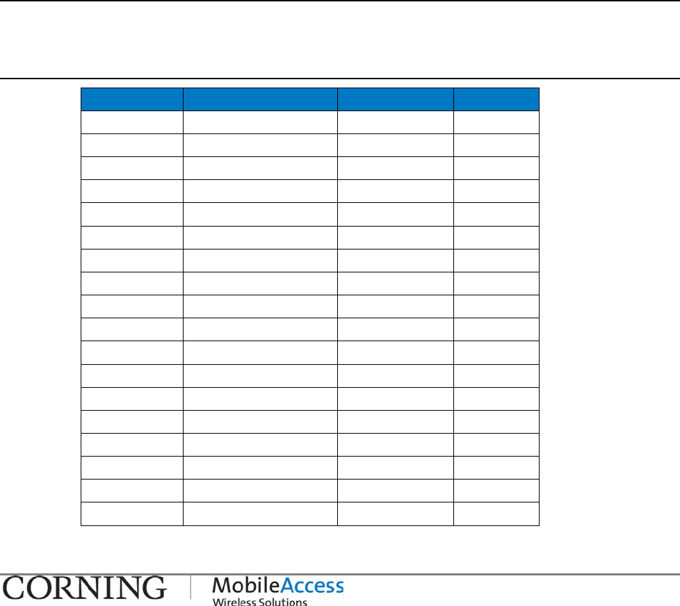
Table 3-1: Package Contents
Kit Item P/N Description QTY.
QX QX chassis - Empty chassis 1
AC Power Cable 705900007
Black, Straight, USA 10A ,UL,
Length=1.8-2.5m , 110V 1
DC Power Cable 705A030821
DC, Power Cable with Open
Edges. Length=5m 1
Flat Cable 705900003 RJ45
to RJ45 communication
cable. Length 2m-2.15m 1
RHU Module –
(service
specific)
QMA Cable 705A042101 QMA to QMA straight cable,
R/A,0.141", Length=430mm 2
Flat Cable (pre-
connected) 705A042601
RJ45 to RJ45 communication
cable. Length=700mm 1
AWS Add-On QMA Cable 705A042101 QMA to QMA straight cable,
R/A,0.141", Length=430mm 1
LTE Add-On QMA Cable 705A042101 QMA to QMA straight cable,
R/A,0.141", Length=430mm 1
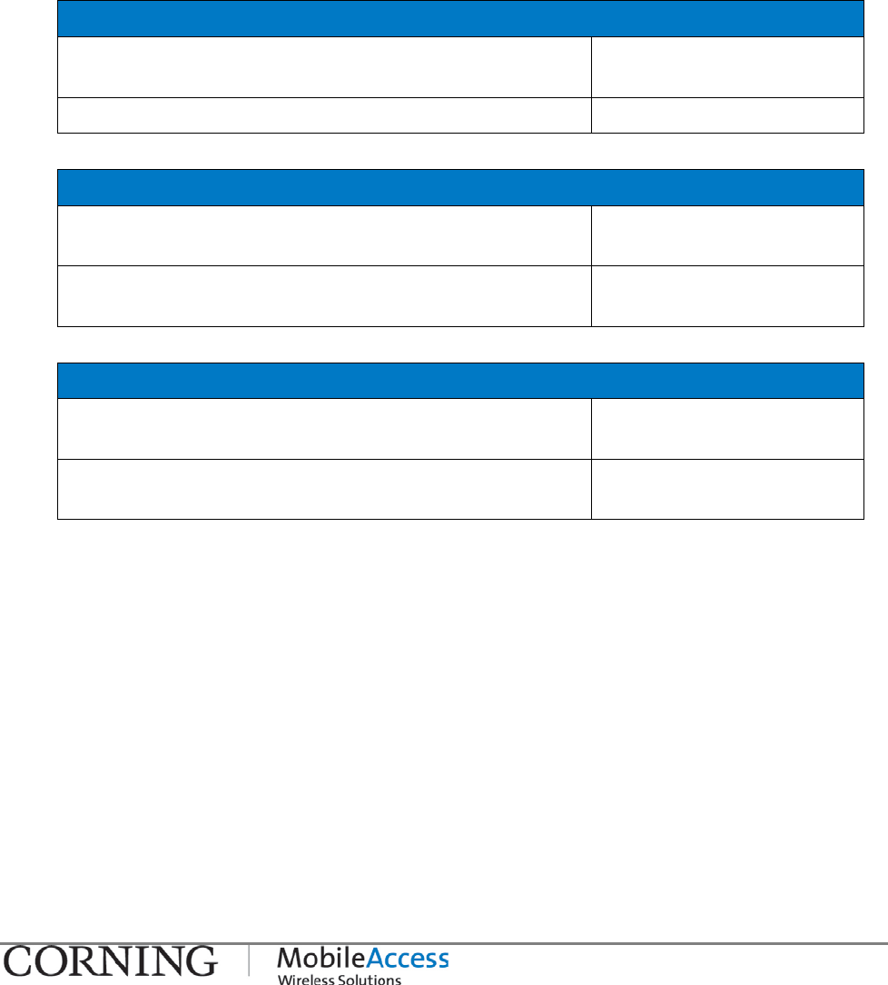
Table 3-2: SCU-F Package Contents
Kit Item P/N Description QTY.
SCU-F SCU-F SCU-F Four Port Service Combiner Unit with 1
DB-15 to DB-15
Digital Cable 705A042301 Used for connecting the SCU-F DB-15
port to the QX DB-15 port (internal
AMU module interface)
1
Inserting an RHU/AO Module in to QX Chassis I P/N 709C011101 I Page 14
3.3 Inserting an RHU/AO Module in to QX Chassis
The QX chassis and Remote Hub Unit (RHU) and Add-On (AO) modules are provided separately,
whereas the modules must be inserted in to the chassis. This requires opening the QX chassis
front panel door and inserting the modules into their respective slots.
The RHU/AO modules are hot swappable and can be inserted either before or after the system
installation.
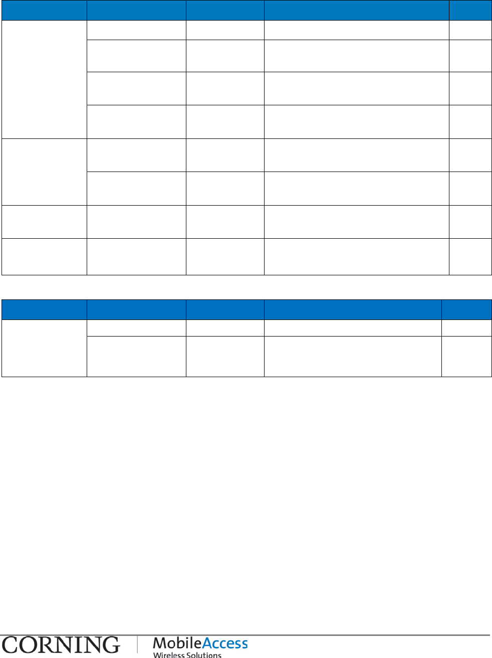
To insert an RHU/AO Module
1. Open the QX door, by unscrewing the two captive screws.
QX Front Door Screws Figure 3-1
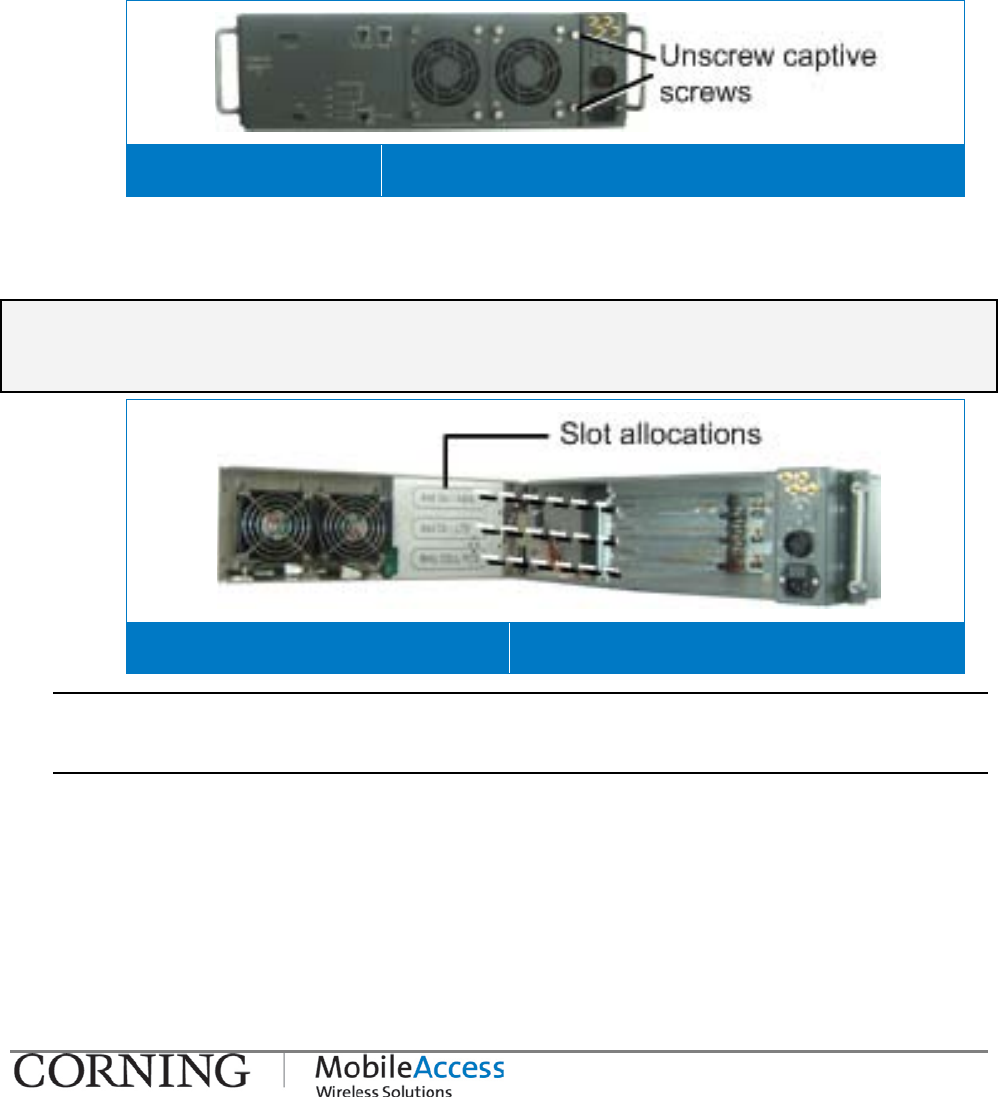
2. Referring to the slot allocation labels inside of the chassis door, position the service module
in the relevant slot with the handle facing front. Refer to Figure 3-2.
IMPORTANT!
Dummy modules must be inserted in unoccupied slots for termination.
Slot Allocations for Service Modules Figure
3-2
NOTE 1: Termination modules are required for unoccupied slots – ordered separately.
NOTE 2: When installing an LTE AO unit, an indication of the use of an internal or external filter must be
selected – via the GUI.
3. Slide the module towards the back of the unit and fit the module ejectors in to the side
notches of the slot (verify that the screws are unscrewed). Refer to Figure 3-3.
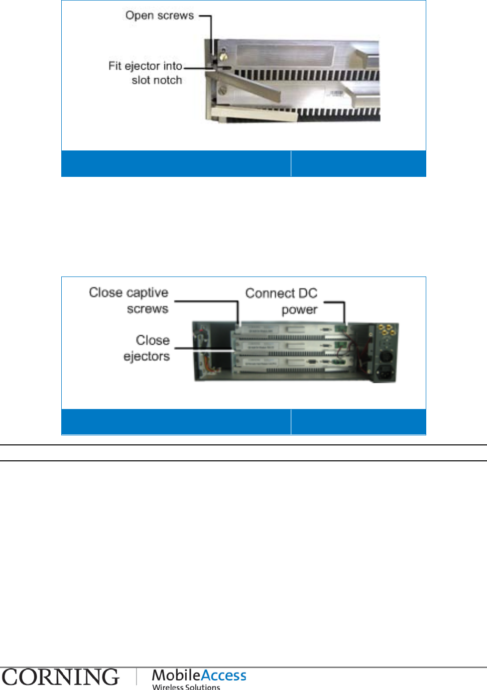
Inserting an RHU/AO Module in to QX Chassis I P/N 709C011101 I Page 15
Positioning New Module in Designated Slot Figure 3-3
4. Push the module all the way back until it “clicks” in to the chassis backplane.
5. Close ejectors and close both captive screws to secure the module in place. Refer to Figure
3-4.
6. For each Add-On module, connect the internal DC power feed to the module DC power
connector. Refer to Figure 3-4.
Securing Module in Slot and DC Connections
Figure 3-4
NOTE: The RHU service module does not have an internal power feed connection.
Mounting I P/N 709C011101 I Page 16
3.4 Mounting
3.4.1 Rack Mount Installations
3.4.1.1 Plan the rack installation
NOTE: The unit can also be wall mounted using dedicated brackets (ordered separately). For wall mounted
units – it is recommended to install the service modules first.
1. Verify that the height of the rack can support QX unit being installed, as well as additional
equipment, SCU-F, AC or DC power, and space for the broadband coax connection. Also
consider room for future expansions.
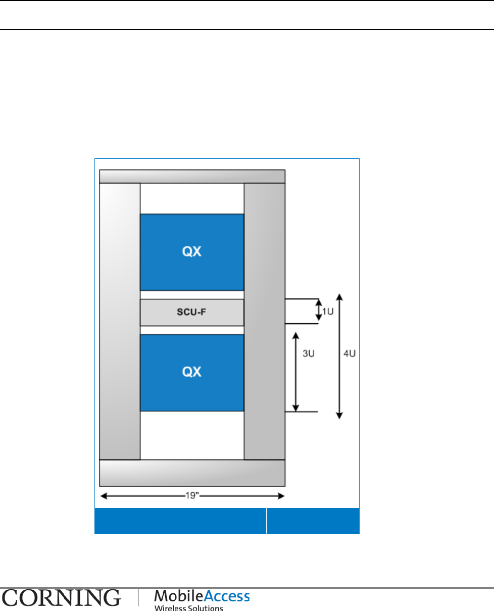
2. If the SCU-F supports more than one QX chassis – install in between QX units. See Figure
3-5.
3. To maintain low center gravity, ensure that heavier equipment is installed near the bottom
of the rack, and that the rack is loaded from top to bottom.
QX and SCU-F Locations in Rack Figure 3-5
Mounting I P/N 709C011101 I Page 17
3.4.1.2 Rack Installation Safety Instructions
Review the following guidelines to help ensure your safety and protect the equipment from
damage during the installation.
• Only trained and qualified personnel should be allowed to install or replace this equipment.
• Verify that ambient temperature of the environment does not exceed 50°C (122°F)
• To maintain a low center of gravity, ensure that heavier equipment is installed near the
bottom of the rack and load the rack from the bottom to the top.
• Ensure that adequate airflow and ventilation within the rack and around the installed
components so that the safety of the equipment is not compromised. It is recommended to
allow for at least about 2 cm of airspace between devices in the rack.
3.4.1.3 Mounting QX Unit in 19-IN Rack
NOTE: The QX can also be mounted on wall – see section 3.4.2
Install the QX in the 19-in rack below the SCU-F (recommended) and secure with pre-
assembled rack ears.
3.4.1.4 Mounting SCU-F Unit
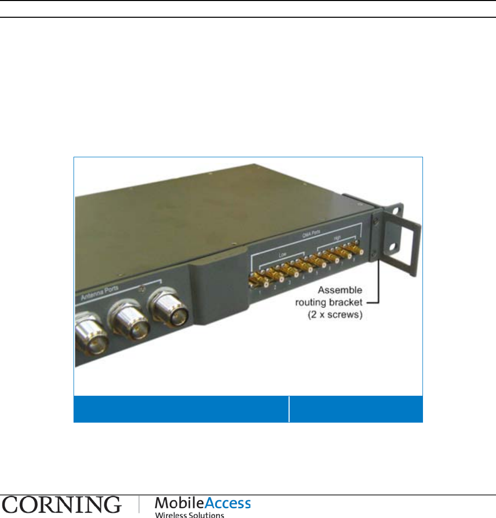
1. Assemble the SCU-F Routing Bracket as follows:
• Unscrew the two screws located on the far right of the SCU-F front panel. Save the screws
for next step.
• Assemble the supplied Routing Bracket on to the right side of the SCU-F front panel using
the two screws previously removed. See Figure 3-6.
SCU-F with Assembled Routing Bracket Figure 3-6
2. Install the SCU-F unit in the 19-in rack and secure with the factory-assembled rack ears.
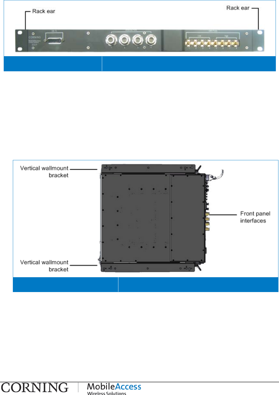
Mounting I P/N 709C011101 I Page 18
SCU-F Pre-assembled Rack Ears Figure 3-7
3.4.2 Wall Mount Installation
There are two wall mount installation options for the QX unit, whereas the SCU-F can also be
mounted on top of the QX chassis so as to accommodate connections between the units:
a. Horizontal Wall Mount (provided with QX) - QX unit is mounted in a horizontal alignment
so that the front panel interfaces face towards the front (as in rack installations). See 0.
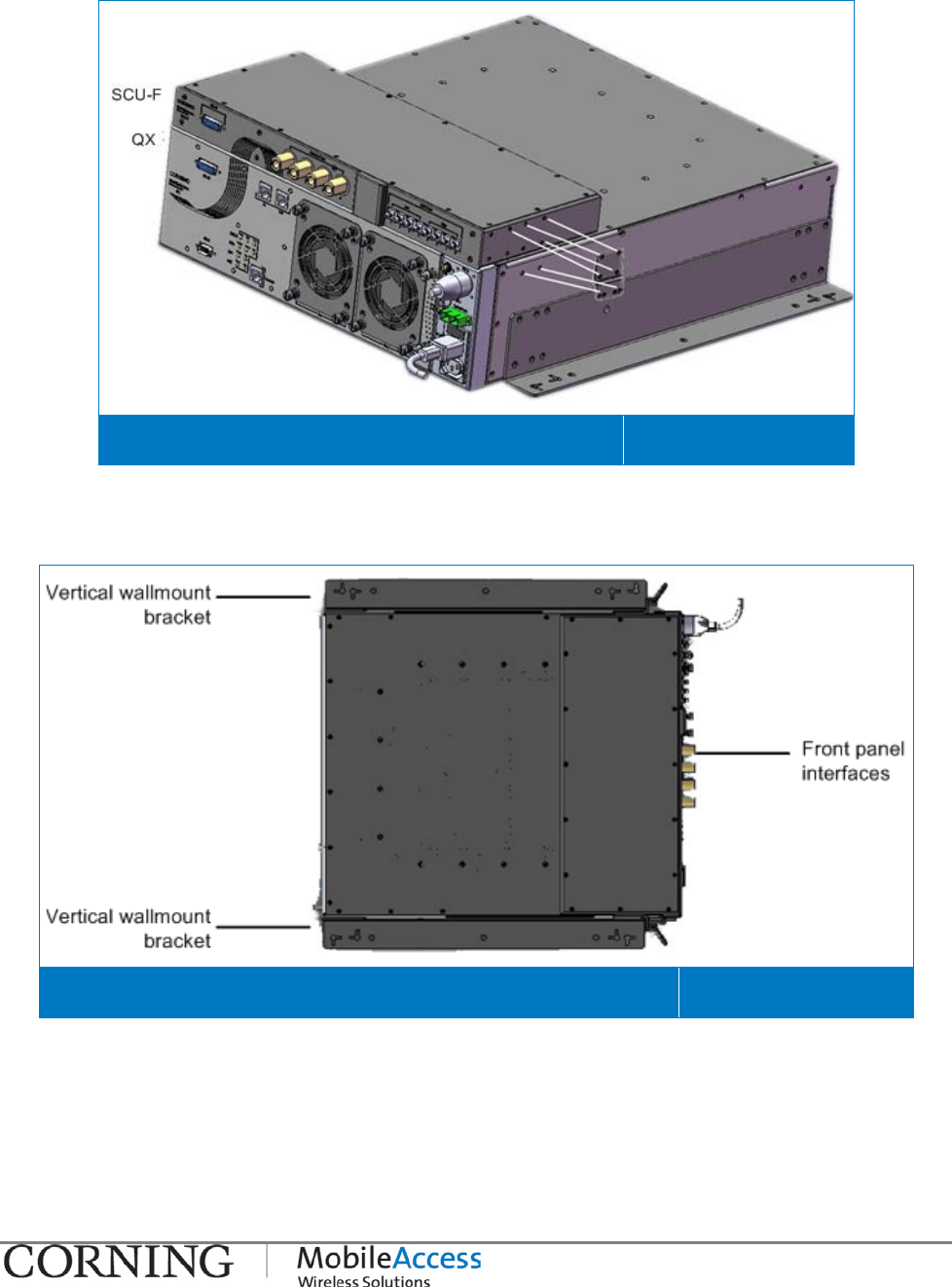
b. Vertical Wall Mount (ordered separately: P/N AK-QX-ENC-WMT-V) – QX unit is mounted
in a vertical alignment so that the front panel interfaces face towards the side. See Figure
3-8.
QX Vertical Wall Mount Alignment Figure 3-8
Mounting I P/N 709C011101 I Page 19
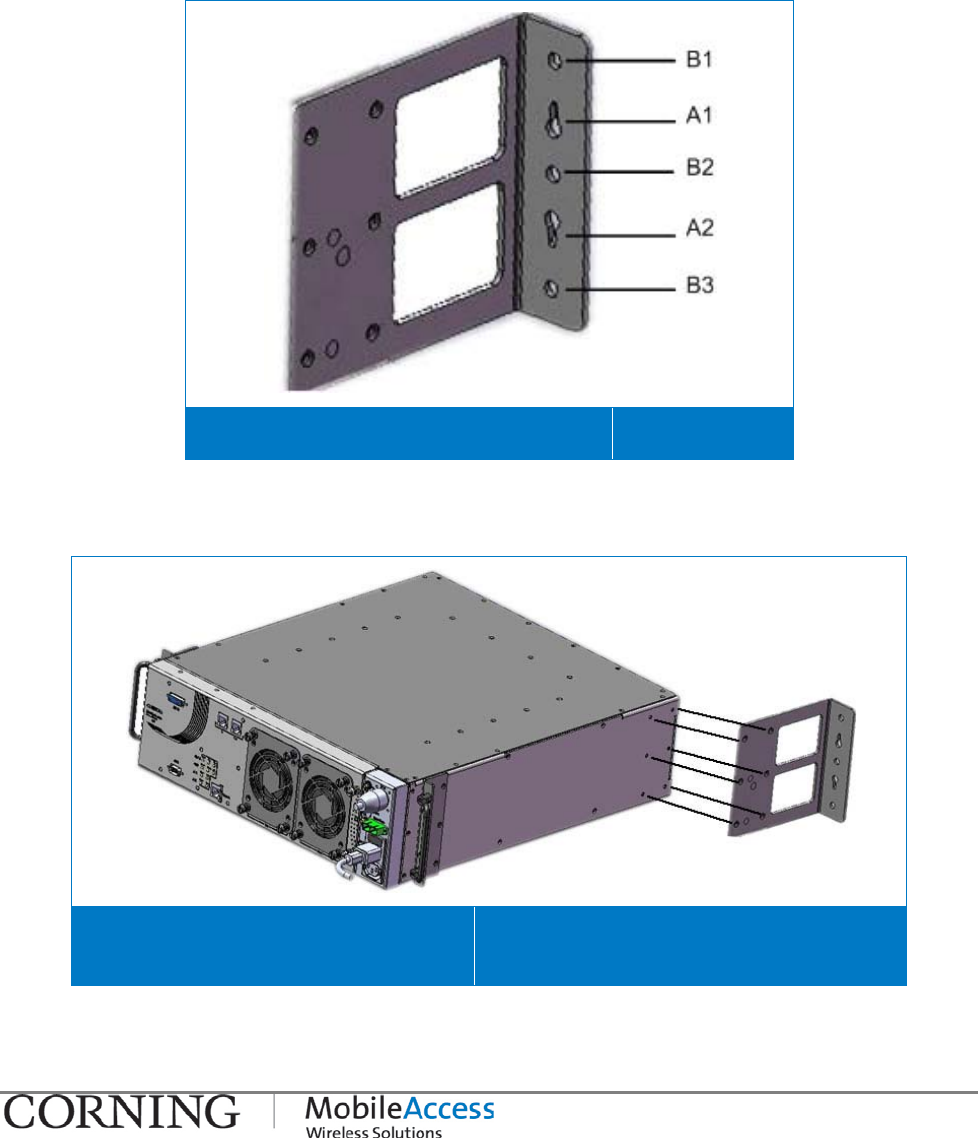
3.4.2.1 QX Horizontal Wall Mount Installation
To mount the QX horizontally on the wall
1. Mark and drill the installation holes in the wall, using the bracket as a guide. There are two
options, as shown in Figure 3-9:
• Holes A1 and A2 are used for securing the brackets to the wall in a fixed position
• Holes B2, B2 and B3 are used for hanging the assembly on anchors
QX Horizontal Wall Mount Bracket Holes Figure 3-9
2. Assemble the brackets on to the QX unit by securing each bracket to the side of the QX
chassis using (6) 6-32X5/16' Flat Head 100', Phillips screws (supplied) as shown in Figure
3-10.
Horizontal Wall Mount Bracket
Assembly Figure 3-10
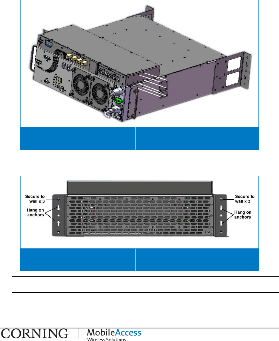
Mounting I P/N 709C011101 I Page 20
3. Optional – mount the SCU-F unit on to the QX chassis:
• Remove the QX side rack ears (pre-assembled) to access the holes required for
assembling SCU-F
• Secure each SCU-F bracket to the side of the QX chassis using the six (6) supplied
screws, as shown in Figure 3-11.
SCU-F to QX Assembly for Wall mount
Installation Figure 3-11
4. Mount the assembly on the wall using one (or both) of the mounting options - hang the QX
on the anchors (previously prepared in wall) and/or secure to wall using the three (3)
additional holes (screws not supplied).
Horizontal Wall Mount Bracket
Assembly – Rear View Figure 3-12
Note: When mounted on the wall, there will be approximately 60mm (2.36”) of space between the wall
and the back of the QX unit.
Mounting I P/N 709C011101 I Page 21
3.4.2.2 QX Vertical Wall Mount Installation
Note: Vertical Wall Mount brackets are ordered separately (P/N AK-QX-ENC-WMT-V).
To mount the QX vertically on the wall
1. Verify that the following items are included in the accessory kit:
Item QTY. Image
Vertical Wall Mount Bracket for QX chassis 2
Screw,4-40X5/16',Flat-HD, 100', Philips, Nerosta 16
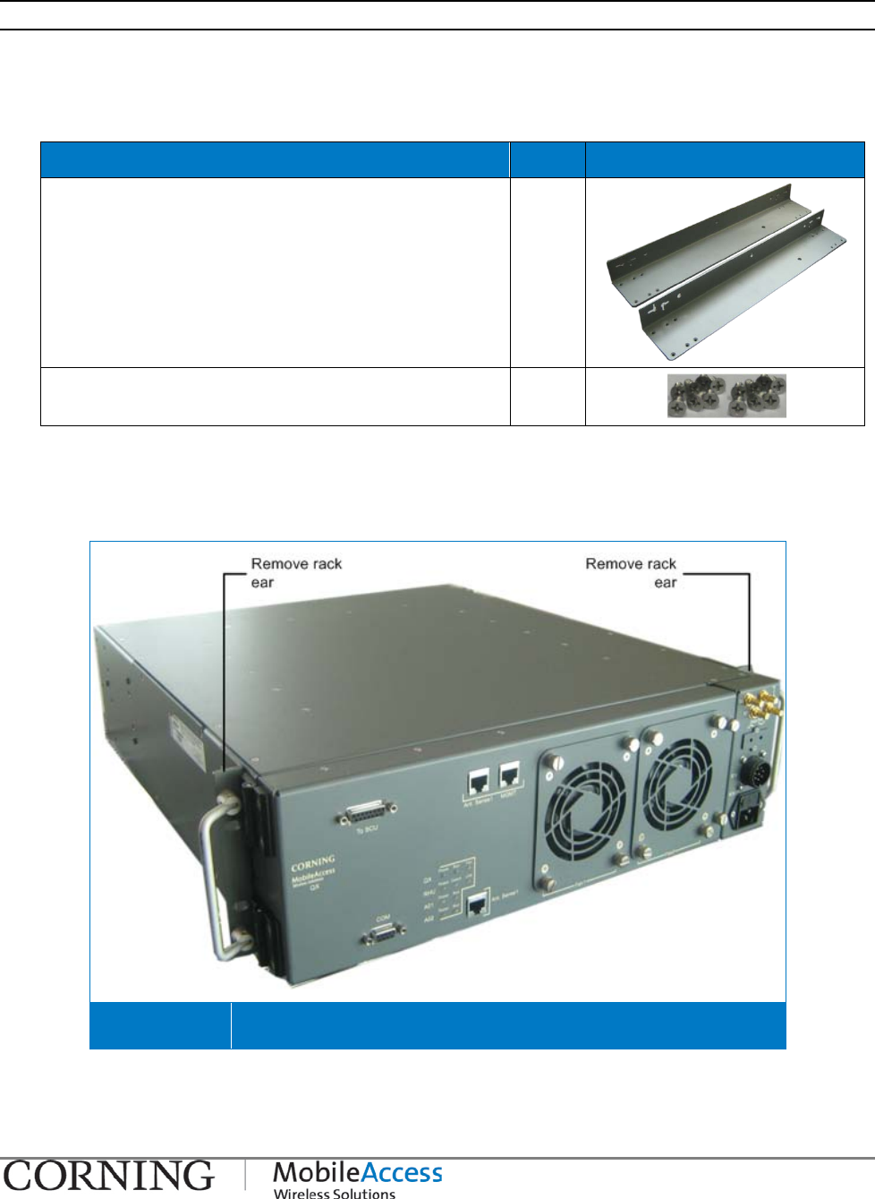
2. Remove the factory assembled rack ears from the sides of the QX chassis so as to access
the relevant screw holes for assembling the QX vertical wall mount brackets. See Figure
3-13.
QX Rack Ears Figure 3-13
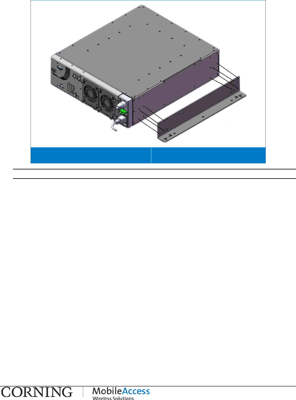
Mounting I P/N 709C011101 I Page 22
3. Assemble the vertical wall mount brackets on to the sides of the QX chassis using the eight
(8) provided screws, as shown in Figure 3-14
Vertical Wall Mount Bracket Assembly Figure 3-14
Note: You may want to mark the mounting holes on the wall (according to brackets) prior to mounting.
4. Select the appropriate location on wall for the QX unit. Verify that:
• There is enough free space around the unit for ventilation
• Location enables opening the enclosure door to the side
5. (If not already marked) Mark the mounting holes on the wall according to the bracket holes
and drill appropriate holes.
Mounting I P/N 709C011101 I Page 23
6. Optional – mount the SCU-F unit on to the QX chassis by securing each SCU-F bracket to the
side of the QX chassis with the six (6) supplied screws, as shown in Figure 3-15.
SCU-F to QX Assembly for Wall mount Installation Figure 3-15
7. Mount the QX chassis on the wall with the panel interfaces facing towards the side, as
shown in Figure 3-16.
QX (with SCU-F on top) Vertical Mount Installation – Front View Figure 3-16
Connections I P/N 709C011101 I Page 24
3.5 Connections
The system connections required for the QX consist of the following:
• Fiber optic connections to the RF to fiber optic converter unit at the headend – BU or OCH
• RF and Antenna connections:
• RF service connections to the four port Service Combiner Unit (SCU-F)
• Antenna connections between the SCU and the broadband antennas
• (QX) AMU module connections to SCU
• Power – Local (AC) or Remote (DC)
The connections are described in the following sections.
3.5.1 QX Fiber Optic Connections
Note: Keep in mind the rules for handling and connecting F/O cables. The F/O cables will be connected to the
associated BU/OCH in the communication room at a later phase.
To connect fiber optic cabling
1. (If not already installed) Install splice box near the QX chassis.
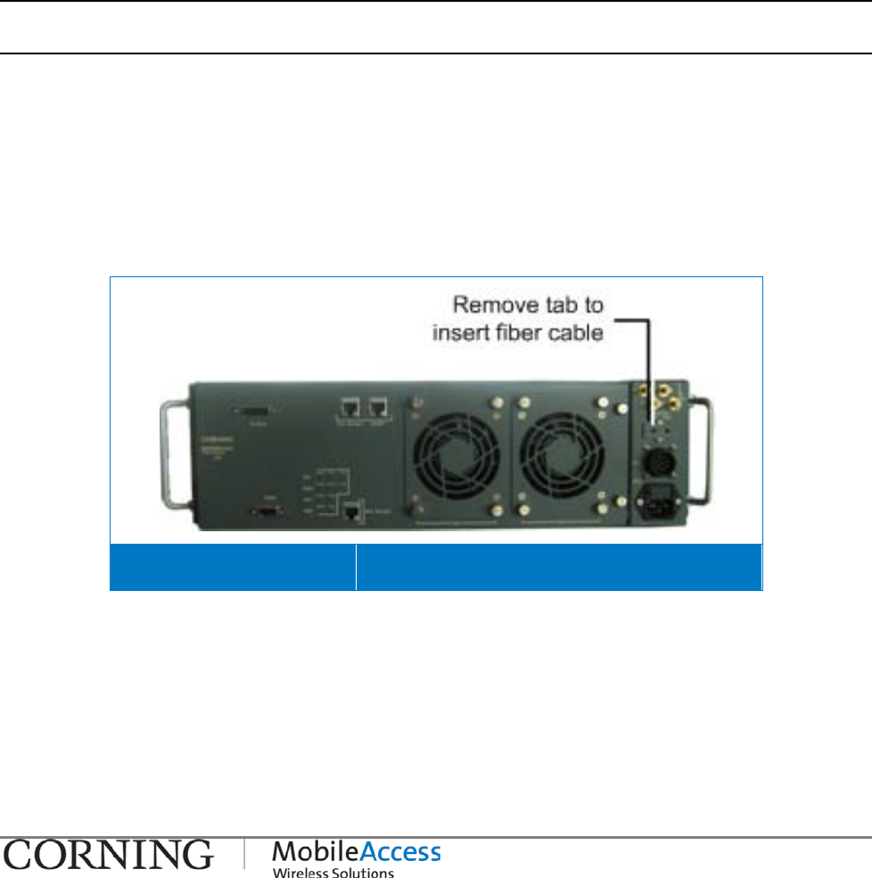
2. Referring to Figure 3-16, remove the tab (both parts) covering the fiber slot (located on port
panel) and set aside. Route the fiber through the slot and connect to the RHU SC/APC
To/From ports, Refer to Figure 3-18 .
3. Replace the fiber slot tab (both parts).
Removing Fiber Slot Tab Figure 3-17
Connections I P/N 709C011101 I Page 25
Routing Fiber to Connection Port Figure 3-18
Note: See section 3.5.1.1 for MIMO connections to RF to Fiber optic converter unit (BU/OCH).
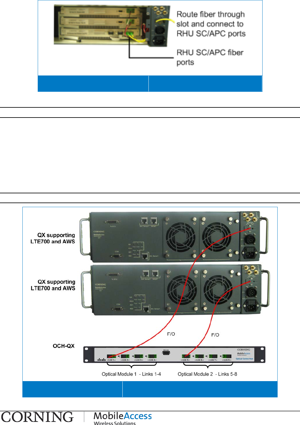
3.5.1.1 MIMO Configurations
Two QX units supporting the LTE700 and AWS bands can provide MIMO service coverage.
For MIMO configurations
Connect the fiber optic port of each of the two QX units’ supporting the LTE 700 and AWS
(SISO) bands to a different BU/OCH optic module (see section 3.5.1 for description of
connections). See Figure 3-19 for example of MIMO connections to OCH.
Note: Connections are the same between QX and Base Unit (BU) as for OCH.
QX to OCH MIMO Connections Figure 3-19

Connections I P/N 709C011101 I Page 26
3.5.2 RF Connections
This section provides information describing the following connections:
• RF (SISO) and antenna monitoring connections between QX and SCU-F
• MIMO connections between QX and SCU-F
• SCU-F to broadband antenna infrastructure connections
3.5.2.1 QX RF and Antenna Monitoring Connections
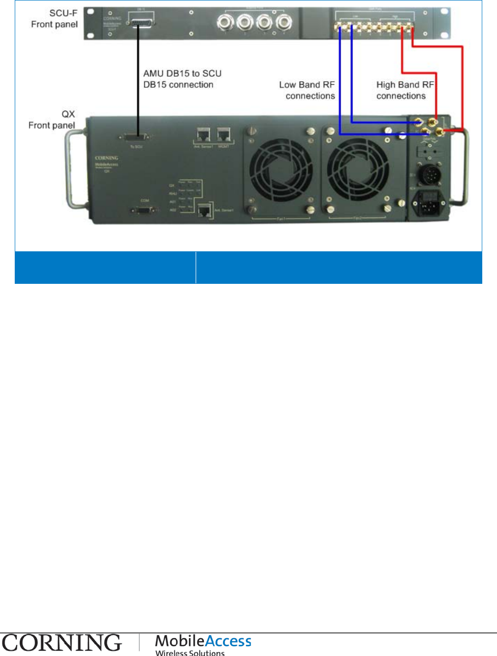
To connect the RF service and antenna connections (refer to Figure 3-20)
1. Connect the QMA to QMA RF jumper cables (provided with each ordered service module) to
the service specific QX RF QMA connector.
2. Route the cables through the assembled SCU-F Routing Bracket (see 3.4.1.4).
3. Connect the other side of the jumper cables to the relevant SCU-F low band (ports 1-4)
and/or high band (ports 5-8) QMA ports.
The connections shown in Figure 3-20 show an example of connections performed for the
CELL/PCS/700LTE/AWS services:
• QX High-frequency band mobile service to SCU-F High Ports (1 - 4) (e.g. AWS and PCS)
(shown in blue)
• QX Low-frequency band mobile service to SCU-F Low Ports (5 - 8) (e.g. CELL and
LTE700) (shown in red)
IMPORTANT! Terminate any unused ports.
NOTE: Refer to section
3.5.2.2for connections required for MIMO configurations.
Connections I P/N 709C011101 I Page 27
04. Connect the QX internal AMU module (for antenna sensing) to the SCU by connecting the
DB15 female connector to the corresponding SCU DB15 female connector, using
corresponding cable provided with the SCU-F (P/N 705A042301). See Figure 3-20.
QX RF and Antenna Connections Figure 3-20
Connections I P/N 709C011101 I Page 28
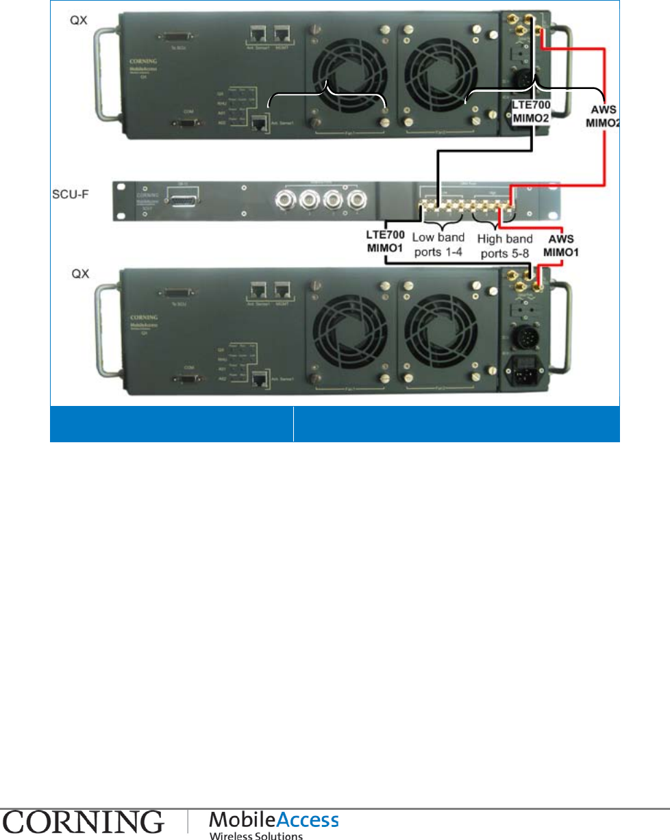
3.5.2.2 RF MIMO Connections to SCU-F
Two QX units supporting the LTE700 and AWS bands can be deployed in a MIMO configuration.
The LTE700 and AWS RF service ports of both QX units are connected to the corresponding low
band and high band SCU-F ports. See Figure 3-21.
QX RF and Antenna Connections Figure 3-21
Connections I P/N 709C011101 I Page 29
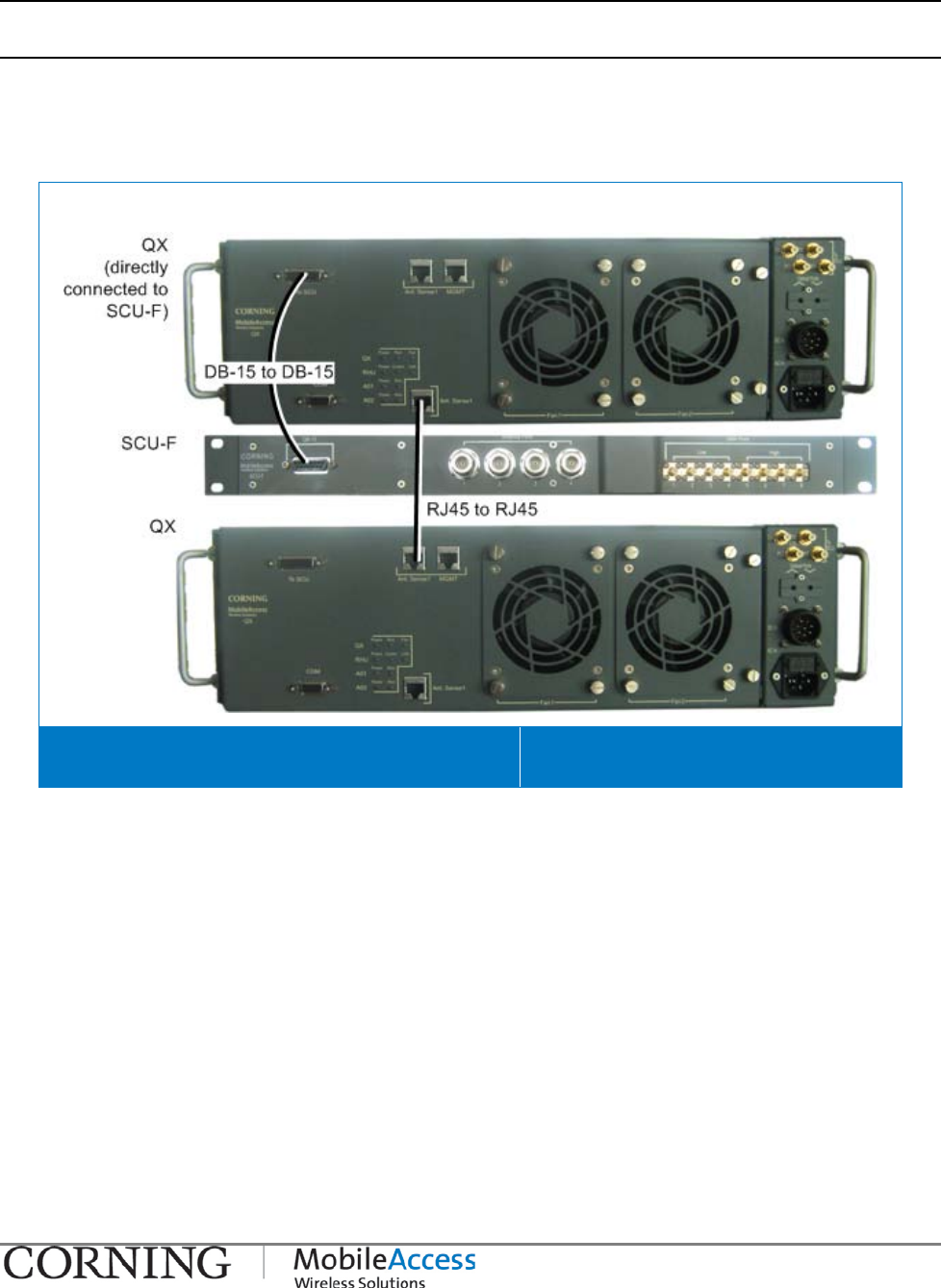
3.5.2.3 Daisy Chaining the AMU modules of Multiple QX Units to a Single SCU-F
NOTE: If installing more than one QX unit, they can be interconnected so that the antenna sense function is
performed by a single AMU (Antenna Monitoring Unit) located inside the QX unit.
Connect one of the two front panel ANT. Sense1 RJ45 connectors of the QX unit directly
connected to the SCU-F DB-15 port to the ANT. Sense1 port of the additional QX unit using
the RJ45 to RJ45 cable provided with the QX (P/N 705900003). It is recommended to connect
the ports closest to each other. See Figure 3-22.
Daisy Chaining AMU to SCU-F Connections Figure 3-22
Connections I P/N 709C011101 I Page 30
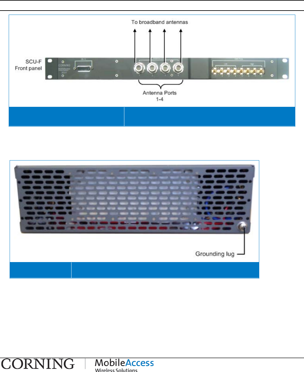
3.5.2.4 SCU-F to Broadband Antenna Connections
To connect the broadband antennas
The QX is connected to the antenna infrastructure via the Service Combiner Unit (SCU-F).
Connect the SCU-F front panel N-Type RF Antenna Ports to the broadband antennas. See Figure
3-23.
Note: Terminate any unused antenna ports with 50 ohm terminators.
SCU-F to Antennas Connections Figure 3-23
3.5.3 Grounding the QX Unit
Ground the QX cabinet via the grounding lug located on the rear.
QX Grounding Lug Figure 3-24
Connections I P/N 709C011101 I Page 31
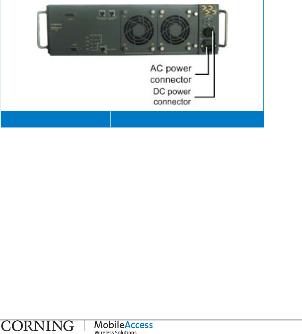
3.5.4 Power Connections
The QX supports both local powering (100-240VAC) and remote powering (25 to 48VDC)
options. Both types of power cables are provided with the unit (see section 3.2).
Connect the power source to the QX using either Local or Remote power (both are supported):
AC In - Local Power: 100-240VAC (Integrated AC/DC converter)
DC In - Remote Power: 25 to 48VDC
Refer to for Figure 3-25 location of power connectors.
QX Power Connection Interfaces Figure 3-25
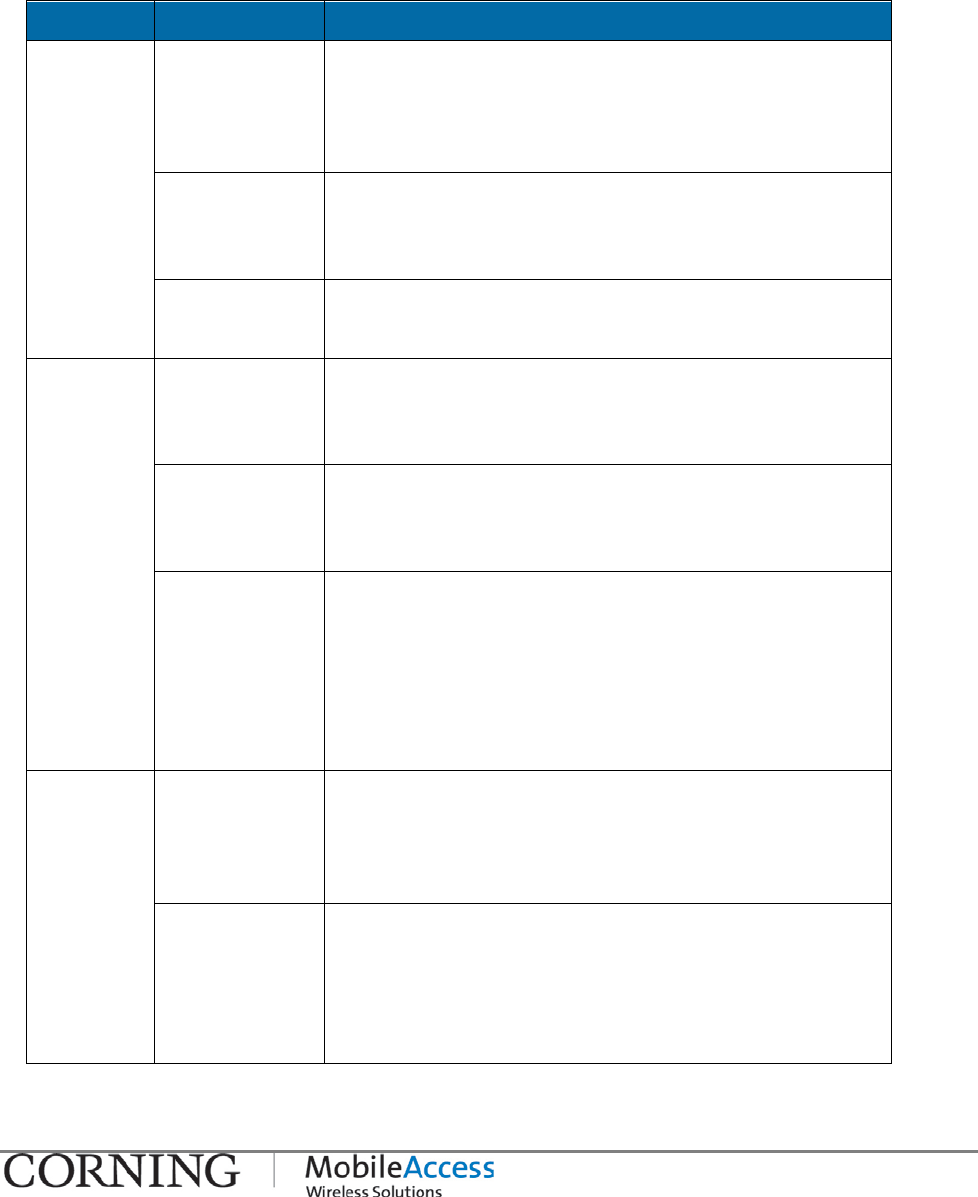
Verifying Normal Operation I P/N 709C011101 I Page 32
3.6 Verifying Normal Operation
Upon powering up the QX remote unit:
• Confirm the fans are working after powering
• Verify normal operation:
Module LED Description
QX Power Steady Green:
Required power is supplied to AMU
module of QX chassis
Off: No power supplied to AMU module of QX
chassis
Run Steady Green: AMU module SW initialized
Blinking
Green: AMU module SW is initializing (blinks for
the duration of approx. 1 minute)
Fan Steady Green: Fan status normal
Red: Faulty fan, alarm triggered
RHU Power Steady Green:
Power input detected for RHU
module
Off: No power detected for RHU module
Comm Blinking
Green: Active communication detected
Red: Faulty communication link
Link Steady Green:
Normal optical link level from
BU/OCH-QX
Blinking
Green: Low optical link level from BU/OCH-
QX
Off:
No optical link is detected from
BU/OCH-QX
AO1/AO2 Power Steady Green: Power input detected for first/second
Add-On unit
Off: No power detected for first/second
Add-On unit
Run Steady Green:
Boot up sequence for first/second
Add-
On unit complete and
functioning
Blinking
Green:
Boot up sequence for first/second
Add-On unit in process
Verifying Normal Operation I P/N 709C011101 I Page 33
LED Indication of Normal Operation Figure 3-26
Replacing an RHU/AO Module I P/N 709C011101 I Page 34
4 Maintenance
This section provides maintenance information on the following:
• Replacing existing RHU/AO modules currently in QX chassis
• Replacing the QX chassis fan modules (in case of faulty fans)
4.1 Replacing an RHU/AO Module
This section describes how to replace an existing RHU and/or RHU/AO module. The RHU and AO
modules are easily removed from/added to the QX chassis, while the procedure does not
require powering off the unit (hot-swap).
To Replace an RHU/AO Module
1. Open the QX door, by unscrewing the two screws.
QX Front Door Screws Figure 4-1
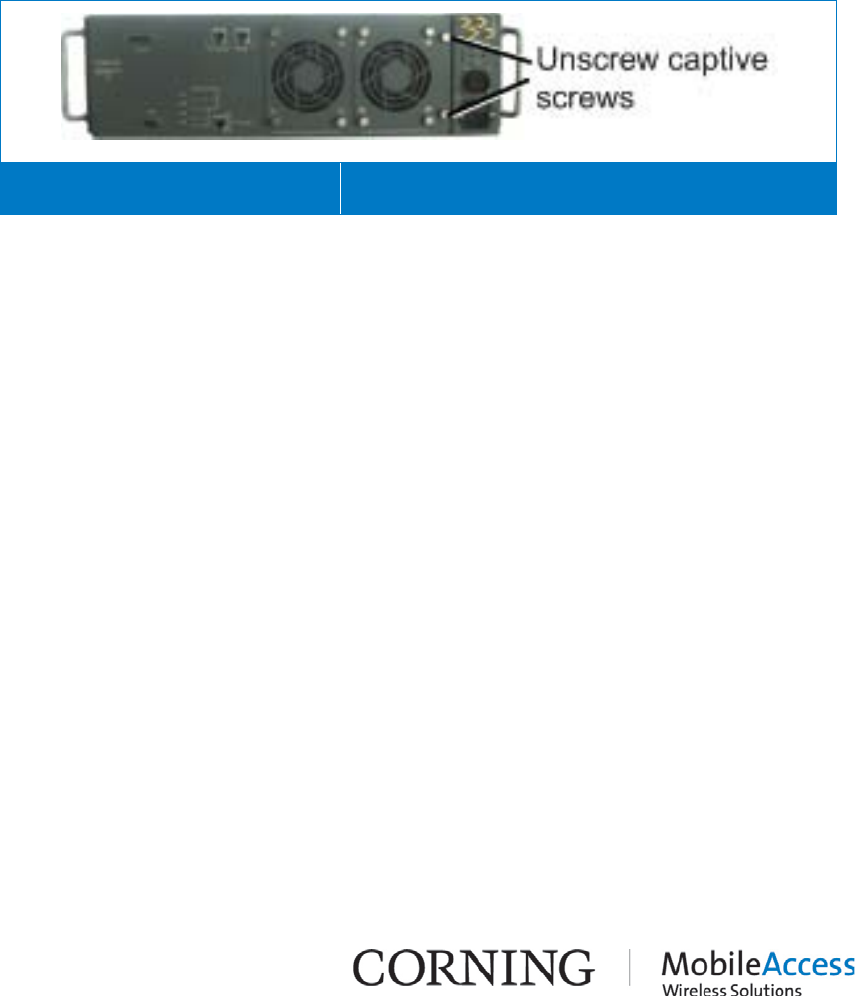
Replacing an RHU/AO Module I P/N 709C011101 I Page 35
2. To remove a module:
NOTE: For partial configurations, a “dummy” module is inserted in the unused service module slot. Does
not include connections.
• Disconnect F/O (RHU) or DC power connection (Add-On) – where relevant
• Open the captive screws securing the module in place
• Open the ejectors and Pull the module out (using the handle)
Removing Service Module Figure 4-2
3. To insert a module – refer to section 0
4. Connect the F/O and power connections to the corresponding ports on the module front
panel.
5. Close the QX chassis door and secure the screws.
6. Connect the relevant RF SMA connector, located on the QX front panel (door), to the SCU.
7. Configure new service via the SC-450 Controller (refer to SC-450 User Manual).
Replacing Fan Module I P/N 709C011101 I Page 36
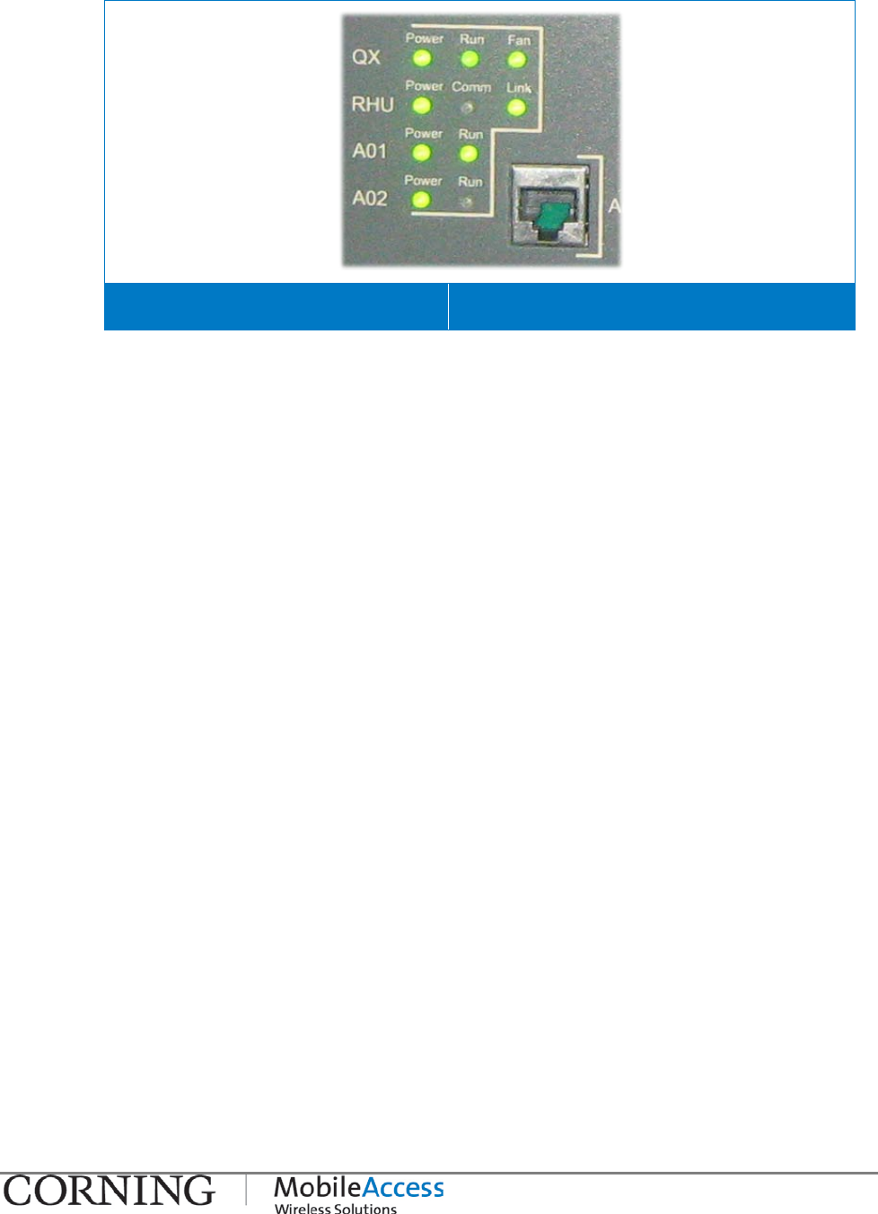
4.2 Replacing Fan Module
In case of faulty fans, they are easily replaced while the procedure does not require powering
off the unit (hot-swap).
To replace faulty fan(s)
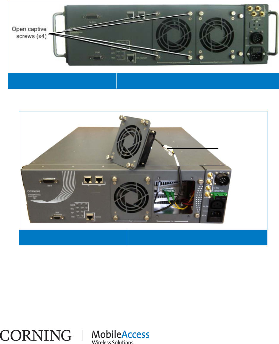
1. Unscrew the four screws securing the fan to the chassis door. See Figure 4-3.
Unscrewing Fan Module Screws Figure 4-3
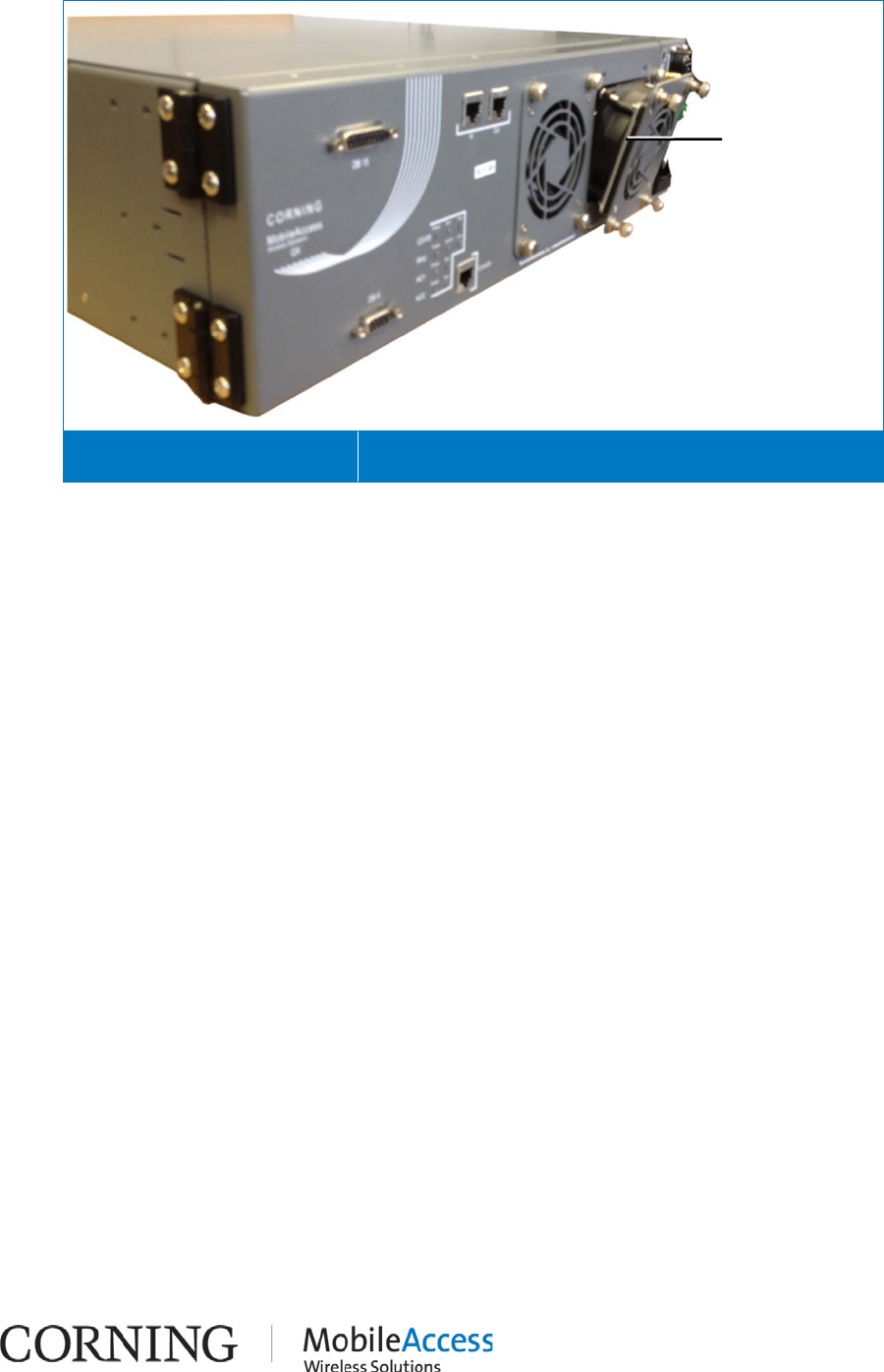
2. Pull out the fan module and disconnect the cable. See Figure 4-4.
Removing Existing Fan Module Figure 4-4
3. Connect new fan module.
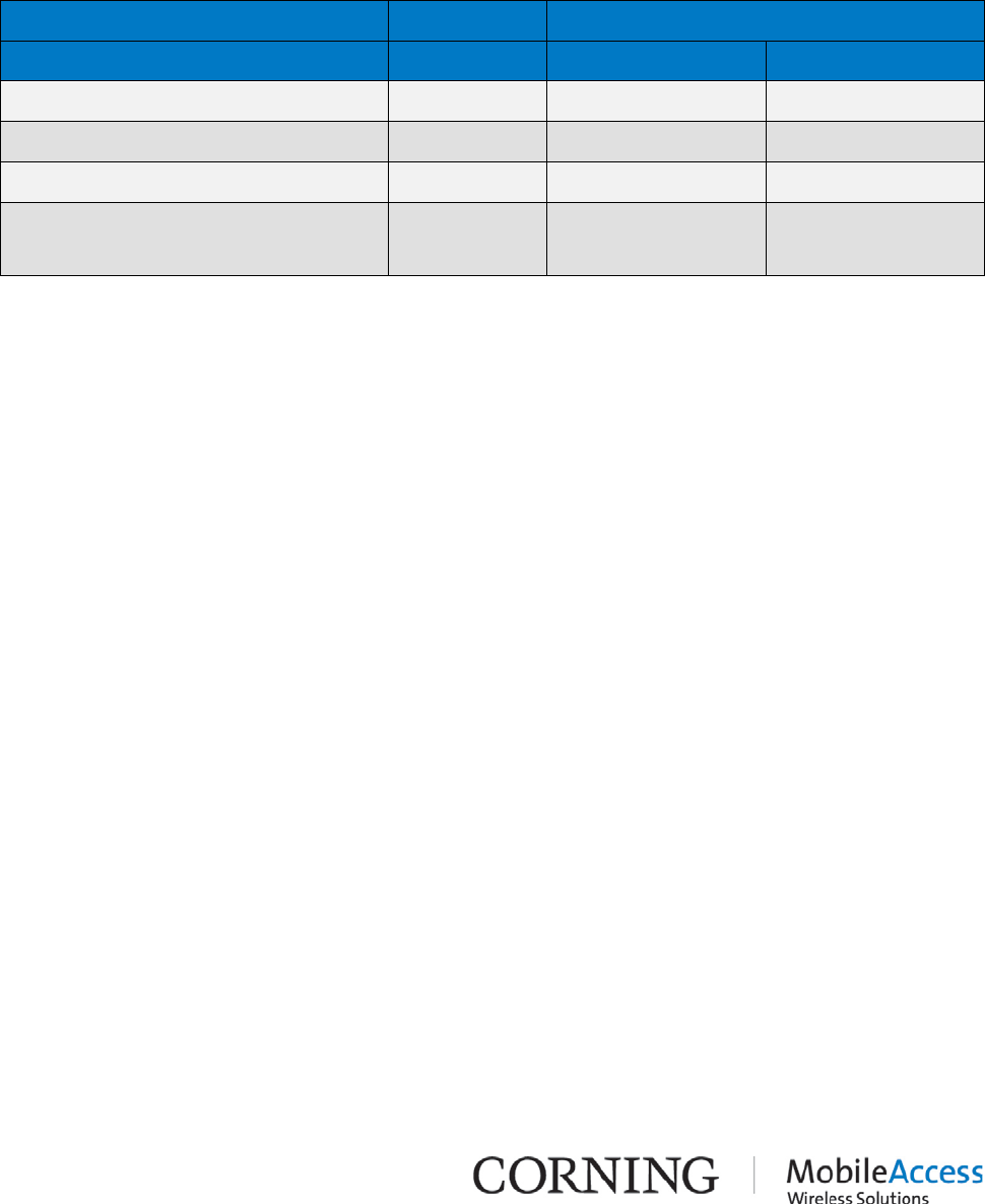
4. Fit the new fan module into place in the chassis door, as shown in Figure 4-5.
Disconnect cable
Replacing Fan Module I P/N 709C011101 I Page 37
Inserting New Fan Module Figure 4-5
5. Tighten the four fan module screws so it is secured to the QX front door panel.
Insert fan module
so that the metal
plates are on each
side
Replacing Fan Module I P/N 709C011101 I Page 38
5 Appendix A: System Specifications
RF Parameters
Supported Services
Technologies Band Frequency Range
Uplink (UL) Downlink (DL)
CDMA/WCDMA**/TDMA/GSM/LTE* CELL800 824-849 869-894
CDMA/WCDMA**/TDMA/GSM/LTE* PCS1900 1850-1915 1930-1995
WCDMA**/LTE* AWS1200 1710-1755 2110-2155
LTE 700 MHz 698-716
776-787 728-746
746-757
(*)WCDMA service is based on 3GPP standards, LTE service may deployed in the future due to Frequencies re-farming
planned by the Carriers as well
(**)WCDMA service is based on 3GPP2 CDMA2000 standards.
Error! Use the Home tab to apply Heading 1 no numbering to the text that you want to appear here. I CMA-xxx-AEN I Page 39
RF Parameters per Service at Antenna Port of Four Port Service Combiner Unit (SCU-
F)
The RF Parameters listed in the tables in this section reflect the specifications at each of the
four antenna ports of the SCU-F when combined with the QX.
RF Parameters
QX RF
Parameters at
Antenna Port of
SCU-F
CELL
TDMA/CDMA/
WCDMA
PCS
CDMA/WCDMA/
TDMA/GSM
AWS
WCDMA
700 MHz
LTE
DL UL DL UL DL UL DL UL
Max Output Power per
Antenna Port
1 Operator
(Composite)
16 - 20 - 21 - 21 -
2 Operators 13 - 17 - 18 - 18 -
4 Operators 10 - 14 - 15 - 15 -
8 Operators 7 - 11 - 12 - - -
12 Operators 5 - 9 - 10 - - -
Mean Gain (dB) 1 16 - 20 3 21 3 21 4***
Pin (dBm) 0 - 0 - 0 - 0 -
Input IP3 (dBm)
AGC OFF Min - -5 - - - - -
Input IP3 (dBm)
AGC ON Min - 5 - -6 - - - -
Input IP3 (dBm) - - - - - -7 - -10
SFDR2 (dB) - 71 - 3 - 66 - 55
Max Intermod
Distortion (dBm) -13* - -13* 64 * - ** -
Max NF (dB) - 20 - 20 - 20 - 20
Gain Flatness/Ripple
(dB) 3 ±2.0 ±2.0 ±1.0
* WCDMA compiles with 3GPP TS 25.106 V5.0.0 (2002-03) table 9.4 spectrum emission mask.
** Out of band and spurious emissions compliant to FCC.
***Default Conditioner (BTSC) UL Gain=+3dB
1Factory set mean gain BU-RHU without RIU. May be field adjusted using controller system.
2SFDR for CDMA services is calculated in 100KB/sec.
3Gain Flatness/Ripple is specified for the non-duplexed port of the system. Overall system typical values.
Error! Use the Home tab to apply Heading 1 no numbering to the text that you want to appear here. I CMA-xxx-AEN I Page 40
Absolute Maximum Rating
Total RF Input Power to BU/OCH 10 dBm
Total RF Input Power to QX RHU Module 20 dBm out-of-band; -10 dBm in-band
Optical Specifications
Optical Output Power < 3.0 mW
Max. Optical Budget
2 dB for fiber + 1 dB for connectors
(assumed) = 3 dB total. 300 m Multi-mode
Optical Loss per Mated-pair Connectors 0.5 dB (max)
Optical Connectors SC/APAC
Fiber Type Single Mode Fiber (SMF): 9/125 µm
Multi Mode Fiber (MMF): 50/125 µm or
62.5/125 µm (Minimum qualifications with
ANSI/TIA/EIA-568-B series, EN50173-
1 or
ISO/IEC 11801
Wavelength 1310 ± 10 nm
Maximum Distance Between Base Unit and
Remote Unit 2 km
Environmental Specifications
Operating Temperature -5°C to +55°C (23°F to 131°F)
Storage Temperature -20°C to 85°C (-4°F to 185°F)
Humidity 10% to 95%, non-condensing
Error! Use the Home tab to apply Heading 1 no numbering to the text that you want to appear here. I CMA-xxx-AEN I Page 41
Standards and Approvals
Laser Safety CDRH 21 CFR 1040.10, 1040.11 (Except for
deviations per notice No.50, July 26, 2001)
IEC 60825-1, Amendment 2 (January 2001)
EN 60825-1
CE Radio Equipment and Systems
EN 301 502 – for GSM / EGSM Frequency
Bands
EN 300 328 – for WLAN 802.11b/g
2.4GHz Frequency Band
EN 301 893 – for WLAN 802.11a 5GHz
Frequency Band
EMC
EN 301 489
FCC Radio Equipment and Systems: FCC 47 CFR
Part 22, 24, 27, 90
EMC: FCC 47 CFR Part 15 Subpart B
Safety EN 60950UL 60950
CAN/CSA-C22.2 No.60950
UL 2043
Error! Use the Home tab to apply Heading 1 no numbering to the text that you want to appear here. I CMA-xxx-AEN I Page 42
System Component Specifications
Quad-Service Package (QX)
Supported Services CELL850; PCS1900; LTE700; AWS2100
Ports To Service Combiner Unit (SCU): (4) 50Ω QMA ports
To Base Unit/Optical Control Hub
(OCH-QX):
(2) SC/APC ports
AMU Master-Slave connections
(2) RJ45 ports
Local connection to AMU module for
SW DL (for service personnel):
(1) RJ45 port
To SCU-4: (1) DB15 connector
RS232 local connection to AMU module
(for service personnel):
(1) DB9 connector
Power Local Power: 100-240VAC (Integrated AC/DC converter)
Remote Power: 25 to 48VDC
Max Power Consumption: 118W
Physical Dimensions Mounting: 19” Rack or Wall (pre-assembled brackets)
17.1x14.5x5.2 (in) 434x369x133 (mm) (WxDxH)
Weight: ~40 lb (~18 kg)
Cooling Features Active heat dissipation (Fan)
Four - Port Service Combiner Unit (SCU-F)
Supported Services High band (1710 MHz - 2170 MHz) and low band (698 MHz –
960 MHz) RF services
Ports
To QX: (8) 50Ω QMA connectors
To Wideband antennas: (4) N-Type 50Ω connectors
For local maintenance: (1) DB15 connector
Physical Dimensions Mounting: 19” Rack (pre-assembled brackets)
17.04x1.72x10.63 (in) 434x440x270 (mm) (WxDxH)
Weight: 6.6 lb (3 kg)

Error! Use the Home tab to apply Heading 1 no numbering to the text that you want to appear here. I CMA-xxx-AEN I Page 43
6 Appendix B: Ordering Information
NOTE: The information listed below is updated up to the document publishing date. Refer to the
QX datasheet for the most updated ordering information.
QX Chassis and Modules
Part Number Description
2000-QX-B-QC QX Chassis without Public Safety Support (termination modules not
included; no coexistence with Public Safety)
2000-QX-B-QCF QX Chassis with Public Safety Support (termination modules not included;
supports coexistence with Public Safety)
2000-C85P19-B-RHM QX Cell & PCS SISO Remote Hub Module (with Single-Mode Fiber
Support)
2000-C85P19-B-RHM
QX Cell & PCS SISO Remote Hub Module (with Multi-mode Mode Fiber
Support)
2000M-C85P19-B-RHM QX LTE SISO Add-on module;
2000-L70-B-AM QX AWS SISO Add-on module
2000-A17-B-AM
QX Cell & PCS SISO Remote Hub Module (with Single-Mode Fiber
Support)
QX Accessory Kits
Part Number Description
2000-QX-B-FAM QX field replaceable Fan
2000-SCU-8-4-F 8 x 4 Service Combiner Unit with all connectors in the front
2000-L70-B-TM QX LTE SISO Add-on port termination module;
2000-A17-B-TM QX AWS SISO Add-on port termination module;
AK-QX-ENC-WMT-V QX mounting brackets and screws to mount the chassis flush to the wall