Corning Optical Communication VE-CELL-PCS12E EnCOVER VE CELL-PCS SYSTEM User Manual USERS MANUAL
Corning Optical Communication Wireless EnCOVER VE CELL-PCS SYSTEM USERS MANUAL
Contents
- 1. USERS MANUAL
- 2. Users Manual
USERS MANUAL

EnCOVER VE™ Dual-Band
Instant Coverage Solution
User Manual
REV:A00
Date: DEC 2009

Preface Material
Dual Band EnCOVER VE™ Instant Coverage Solution User Manual II
MobileAccess
8391 Old Courthouse Road, Suite 300, Vienna, VA 22182
Tel: +1(866)436-9266, +1(703)848-0200 TAC: +1(800)787-1266, Fax: +1(703)848-0280
http://www.MobileAccess.com

Preface Material
Dual Band EnCOVER VE™ Instant Coverage Solution User Manual III
Preface Material
© Copyright 2009, MobileAccess Networks Inc. All Rights Reserved.
MobileAccess™ is a registered trademark of MobileAccess. This document contains other trademarks, trade names and
service marks of MobileAccess and other organizations, all of which are the property of their respective owners.
This document contains confidential and proprietary information of MobileAccess and may not be copied, transmitted,
stored in a retrieval system or reproduced in any format or media, in whole or in part, without the prior written consent of
MobileAccess. Information contained in this document supersedes any previous manuals, guides, specifications, data
sheets or other information that may have been provided or made available to the user.
This document is provided for informational purposes only, and MobileAccess does not warrant or guarantee the
accuracy, adequacy, quality, validity, completeness or suitability for any purpose of the information contained in this
document. MobileAccess reserves the right to make updates, improvements and enhancements to this document and the
products to which it relates at any time without prior notice to the user. MOBILEACCESS MAKES NO WARRANTIES,
EXPRESS OR IMPLIED, INCLUDING, WITHOUT LIMITATION, THOSE OF MERCHANTABILITY AND FITNESS FOR A
PARTICULAR PURPOSE, WITH RESPECT TO THIS DOCUMENT OR ANY INFORMATION CONTAINED HEREIN.
Policy for Warrantee and Repair
MobileAccess tests and inspects all its products to verify their quality and reliability. MobileAccess uses every reasonable
precaution to ensure that each unit meets their declared specifications before shipment. Customers should advise their
incoming inspection, assembly, and test personnel about the precautions required in handling and testing our products.
Many of these precautions can be found in this manual.
The products are covered by the following warranties:
General Warranty
MobileAccess warrants to the original purchaser all standard products sold by MobileAccess to be free of defects in
material and workmanship for one (1) year from date of shipment from MobileAccess. During the warranty period,
MobileAccess will repair or replace any product that MobileAccess proves to be defective. This warranty does not apply to
any product that has been subject to alteration, abuse, improper installation or application, accident, electrical or
environmental over-stress, negligence in use, storage, transportation or handling.
Specific Product Warranty Instructions
All MobileAccess products are warranted against defects in workmanship, materials and construction, and to no further
extent. Any claim for repair or replacement of units found to be defective on incoming inspection by a customer must be
made within 30 days of receipt of shipment, or within 30 days of discovery of a defect within the warranty period.
This warranty is the only warranty made by MobileAccess and is in lieu of all other warranties, expressed or implied.
MobileAccess sales agents or representatives are not authorized to make commitments on warranty returns.

Preface Material
Dual Band EnCOVER VE™ Instant Coverage Solution User Manual IV
Returns
In the event that it is necessary to return any product against above warranty, the following procedure shall be followed:
1. Return authorization is to be received from MobileAccess prior to returning any unit. Advise MobileAccess of the model,
serial number, and discrepancy. The unit may then be forwarded to MobileAccess, transportation prepaid. Devices
returned collect or without authorization may not be accepted.
2. Prior to repair, MobileAccess will advise the customer of our test results and any charges for repairing customer-caused
problems or out-of-warranty conditions etc.
3. Repaired products are warranted for the balance of the original warranty period, or at least 90 days from date of
shipment.
Limitations of Liabilities
MobileAccess's liability on any claim, of any kind, including negligence for any loss or damage arising from, connected
with, or resulting from the purchase order, contract, quotation, or from the performance or breach thereof, or from the
design, manufacture, sale, delivery, installation, inspection, operation or use of any equipment covered by or furnished
under this contact, shall in no case exceed the purchase price of the device which gives rise to the claim.
EXCEPT AS EXPRESSLY PROVIDED HEREIN, MOBILEACCESS MAKES NO WARRANTY, EXPRESSED OR IMPLIED, WITH
RESPECT TO ANY GOODS, PARTS AND SERVICES PROVIDED IN CONNECTION WITH THIS AGREEMENT INCLUDING,
BUT NOT LIMITED TO, THE IMPLIED WARRANTIES OF MERCHANTABILITY AND FITNESS FOR A PARTICULAR PURPOSE.
MOBILEACCESS SHALL NOT BE LIABLE FOR ANY OTHER DAMAGE INCLUDING, BUT NOT LIMITED TO, INDIRECT,
SPECIAL OR CONSEQUENTIAL DAMAGES ARISING OUT OF OR IN CONNECTION WITH FURNISHING OF GOODS, PARTS
AND SERVICE HEREUNDER, OR THE PERFORMANCE, USE OF, OR INABILITY TO USE THE GOODS, PARTS AND SERVICE.
Reporting Defects
The units were inspected before shipment and found to be free of mechanical and electrical defects.
Examine the units for any damage that may have been caused in transit. If damage is discovered, file a claim with the
freight carrier immediately. Notify MobileAccess as soon as possible.
NOTE: Keep all packing material until you have completed the inspection
Safety Warnings
To comply with FCC RF exposure compliance requirement, adhere to the following warnings:
Warning! The Access Pod with its built-in antenna must be installed with a separation distance of at least 20cm from all
persons and must not be located in conjunction with any other antenna.
Warning! The outside antenna must be installed with a separation of at least 20cm from all persons and must not be
located in conjunction with any other antenna.
Warning! Use of this Access Pod with antennas other than those illustrated could be hazardous. Before using other
antennas, contact Mobileaccess Support.
Approved Antennas for use with the EnCOVER VE™ Solution
The gain of external antennas connected to the VAPs should not exceed 10 dBi.
Compliance with RF Safety Requirements
MobileAccess™ products have no inherent significant RF radiation.
The RF level on the down link is very low at the downlink ports. Therefore, there is no dangerous RF radiation when the
antenna is not connected.
Preface Material
Dual Band EnCOVER VE™ Instant Coverage Solution User Manual V
Certification and Compliance to Standards
Category Standards
Safety: IEC 60950-1: 2003; UL-60950-1:2003; CAN/CSA – C22.2 No 60950-1-03
EMC: EN 301489-8 V1.2.1:2002; EN 301489-1 V1.5.1:2004; EN 61000 V4.6:2005
EN 55022 V4.2:2001 / FCC Part 15; VCCI Class A for VCU and Class B for VAP
Radio: GSM/DCS -
EN-301502 V8.1.2: 2001; EN-301908 v3.2.1:2006; EN 300 609-4 V8.02:2000
CELL/PCS - FCC Part 24
UMTS - EN 301 908-11
SAR Body Testing EN 50385 & FCC OET65C:2001
MTBF
ProductMTBF
(Hours) MTBF (Years) Temperature
EnCOVER VE™ Control Unit262,800 3050degC||122degF
EnCOVER VE™ Access Pod262,800 3040degC||104degF

Preface Material
Dual Band EnCOVER VE™ Instant Coverage Solution User Manual VI
About This Guide
This guide provides essential product functionality with all the information necessary for proper
installation and configuration of the EnCOVER VE™ system.
List of Acronyms
Abbreviation Description
DB Dual Band
PoE Power Over Ethernet
PSE Power Sourcing Equipment
SME Small / Medium Enterprise
STP Shielded Twisted Pair
UTP Unshielded Twisted Pair
VAP EnCOVER VE™ Access Pod
VCU EnCOVER VE™ Control Unit
UMTS Universal Mobile Telecommunications System
EGSM Extended Global System for Mobile communications
PCS Personal Communications Service
DCS Digital Cellular System

Dual Band EnCOVER VE™ Instant Coverage Solution User Manual VII
Table of Contents
1Overview ............................................................................................................................... 1
1.1System Architecture .................................................................................................................. 2
1.2System Elements ...................................................................................................................... 3
1.2.1EnCOVER VE™ Control Unit (VCU) ..................................................................................... 3
1.2.1.1VCU Front Panel .................................................................................................. 4
1.2.1.2VCU Rear Panel ................................................................................................... 6
1.3EnCOVER VE™ Access Pod (VAP) ............................................................................................... 7
1.3.1VAP Types....................................................................................................................... 8
1.3.2System Monitoring and Management ................................................................................. 8
1.3.2.1Integration with an External Fault Management System .......................................... 8
2Installation Workflow ........................................................................................................... 9
3Infrastructure Requirements and Layout Planning ........................................................ 10
3.1General information on Location and Connections ...................................................................... 10
3.2Infrastructure Requirements .................................................................................................... 11
3.3Coverage and Installation Planning ........................................................................................... 12
3.3.1Types of Environments ................................................................................................... 12
3.3.1.1Open environment ............................................................................................. 13
3.3.1.2Standard Environment ........................................................................................ 13
3.3.1.3Dense Environment: ........................................................................................... 14
3.3.1.4Combination of Environments ............................................................................. 14
3.4Planning VAP Layout ............................................................................................................... 14
3.4.1RF Coverage Factors ...................................................................................................... 14
3.4.2Mapping Locations ......................................................................................................... 15
3.4.3Optional Directional Antennas ......................................................................................... 15
3.4.4Installation Plan Example ............................................................................................... 16
4VCU Unit Installation and Configuration .......................................................................... 18
4.1EnCOVER VE™ Control Unit Installation as a Master VCU ............................................................ 19
4.2Auxiliary Connections .............................................................................................................. 20
4.2.1Auxiliary Input Connections ............................................................................................ 20
4.2.2Alarm Output Connections .............................................................................................. 20
4.3EnCOVER VE™ Control Unit Installation as a Slave VCU .............................................................. 21
4.3.1Connections of VAP Ethernet Cables ................................................................................ 22

Table of Contents
Dual Band EnCOVER VE™ Instant Coverage Solution User Manual VIII
4.4Provisioning the EnCOVER VE™ Control Unit ............................................................................. 23
4.4.1Configure the Computer Network Parameters ................................................................... 23
4.4.2Provisioning the Master VCU Unit .................................................................................... 25
4.4.3Provisioning the Slave VCUs ............................................................................................ 32
4.5What Next? ............................................................................................................................ 33
5EnCOVER VE™ Access Pod (VAP) Installation and Commissioning ........................... 34
5.1VAP Installation ...................................................................................................................... 34
5.1.1VAP Kit Contents............................................................................................................ 34
5.1.2VAP Locations and Mounting ........................................................................................... 35
5.1.2.1Desk mount ....................................................................................................... 35
5.1.2.2Wall Mount ........................................................................................................ 36
5.2Verifying Coverage .................................................................................................................. 36
5.3Naming the VAPs, Verifying Connections and Monitoring ............................................................ 36
6Navigating the Management Application ......................................................................... 39
6.1Opening a Session and Authentication Levels ............................................................................ 39
6.2Main Window .......................................................................................................................... 40
6.3Configuration Tab ................................................................................................................... 41
6.3.1VCU Configuration ......................................................................................................... 41
6.3.2Network Topology Tree .................................................................................................. 42
6.3.3Configuration Display Area .............................................................................................. 43
6.3.4Alarms Tab.................................................................................................................... 44
6.3.4.1VCU Alarms Tab ................................................................................................. 44
6.3.4.2VAP Alarms Tab ................................................................................................. 45
6.3.5Module Info................................................................................................................... 46
6.3.6Service Tabs (RF Parameters) ......................................................................................... 47
6.3.6.1Master VCU/Slave VCU Service RF Tab ................................................................. 47
6.3.6.2VAP Service RF Tab ............................................................................................ 48
6.4Management Tab .................................................................................................................... 49
6.4.1Security Tab – Changing Password .................................................................................. 49
7Troubleshooting ................................................................................................................. 50
7.1Finding a Specific VAP in the Building ....................................................................................... 50
Appendix A - Traps ................................................................................................................... 52
Dual Band EnCOVER VE™ Instant Coverage Solution User Manual 1
1 Overview
MobileAccess EnCOVER VE™ Dual-Band solution provides enhanced, cost effective in-building
dual-band coverage for small to large-sized enterprises. This solution is quickly and simply
deployed using the existing Ethernet cabling infrastructure to provide instant coverage without
requiring the installation of new cables.
The EnCOVER VE™ solution distributes two types of services to EnCOVER VE™ Access Pods
(VAPs) installed throughout the enterprise: wireless services from the service provider’s
equipment and Ethernet services from the corporate LAN. The Access Pods distribute the
wireless services via integrated internal antennas, and provide Ethernet connectivity to the LAN
terminals. (Optionally, external antennas can be connected to the Access Pods for additional
coverage optimization).
The VAPs are distributed on each floor and plug into standard Ethernet jacks already installed at
the enterprise site. They are powered via PoE technology and managed via an EnCOVER VE™
Control Unit (VCU) located in the floor’s communication shaft. For site coverage that requires
more than one VCU (each VCU supports up to 12 VAPs), several VCUs (up to 12) can be
aggregated under a single VCU serving as Master. The Master VCU provides the interface to the
capacity source, the service provider’s equipment and for management of all units.
This enhanced Dual Band coverage solution can be easily and quickly installed (in less than a
few hours) with minimal disturbance to the enterprise (as no installation of additional cables is
required).
Currently, the VE™ Dual-Band system is available for the following band combinations:
• EGSM-UMTS
• CELL-PCS
• DCS-UMTS
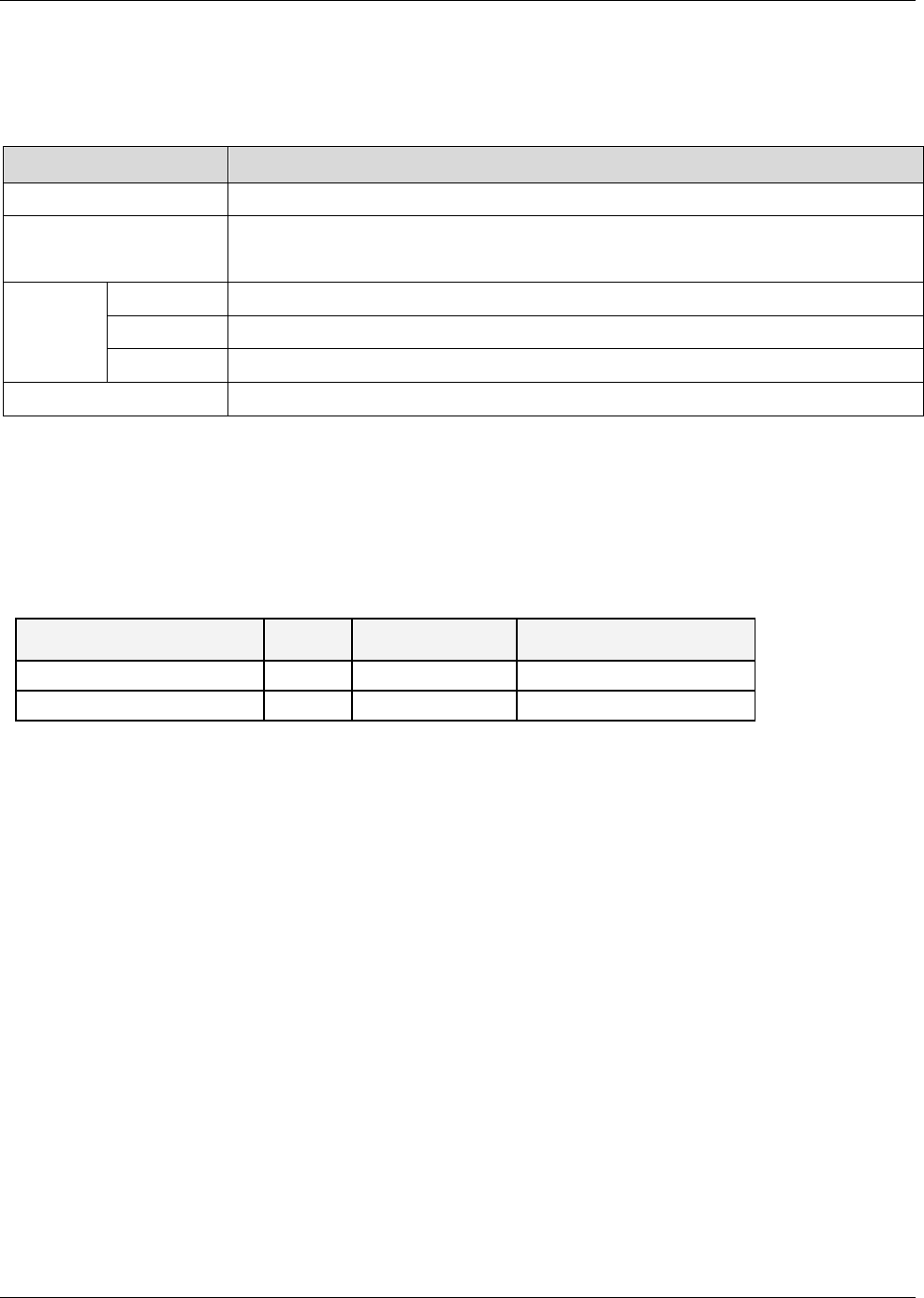
The following figures illustrate single-tier and multi-tier EnCOVER VE™ installations.
In a single-tier installation, the VCU is connected to the service provider’s equipment and to the
Ethernet switch and distributes Ethernet and mobile services to up to 12 VAPs distributed over
one more adjacent floors.
Figure 1. Single Tier VE™ Installation
Overview
Dual Band EnCOVER VE™ Instant Coverage Solution User Manual 2
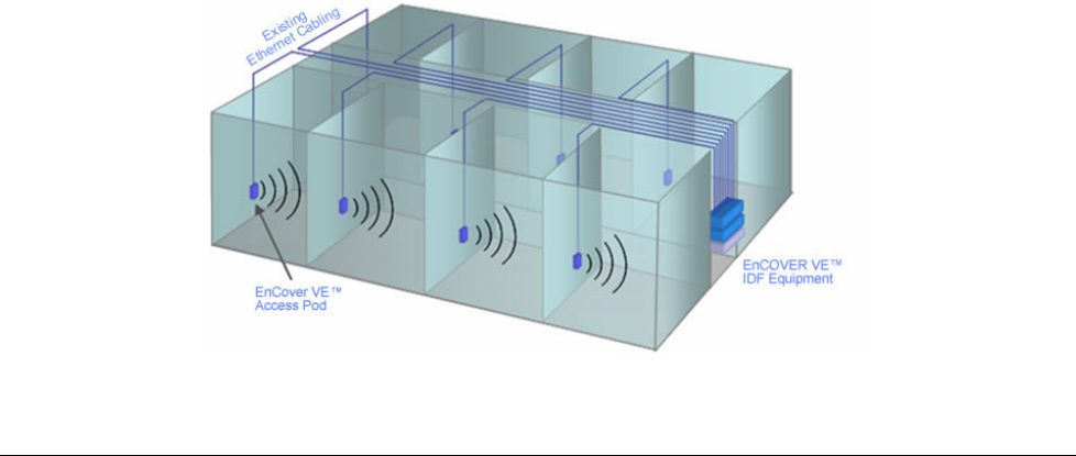
Multi-tier installation includes the Master VCU that supports up to twelve Slave VCUs. In this type
of installation the provider’s services are fed to the Master VCU through which the Slave VCUs
are controlled and managed.
Figure 2. Multi Tier VE™ Installation
1.1 System Architecture
Main elements - The EnCOVER VE™ solution is based on the following main elements:
• VE™ Control Unit (VCU) – Control Unit that can serve either as a Master or a Slave and
interfaces the other VCUs or VAPs accordingly. The physical connection determines whether
the VCU is identified as a Master or Slave VCU unit. If a connection is detected at the RF
source the VCU will be identified as a Master.
• Master VE™ Control Unit (Master VCU) – installed in the main communication (IDF)
closet, interfaces to the service provider’s RF equipment and provides secure, central
management to (up to twelve) VCUs and all connected VAPs.
• Slave VE™ Control Unit (Slave VCU) – installed telco/IDF closet. Used to expand
coverage to additional floors. Each VCU interfaces to the Master VCU and up to 12 VAPs
and 12 Ethernet connections.
The Slave VCUs distribute wireless service signals to each VAP along with PoE and (where
relevant) Ethernet signals from the Ethernet switch, throughout the existing CAT-5e
infrastructure.
The Slave VCUs are connected to the Master VCU using CAT-6 or 7 cables.
•
VAP (EnCOVER VE™ Access Pod)
– These are pluggable antennas distributed at strategic
locations on the floor to provide maximum coverage. VAPs provide RF coverage via integrated,
internal antennas. VAPs equipped with an interface for external antennas are available for
special coverage requirements.
Up to 12 VAPs can be connected to a single VCU using LAN cables (CAT-5e or higher).
Overview
Dual Band EnCOVER VE™ Instant Coverage Solution User Manual 3
Note: The system supports up to 12 VAPs per VCU, where in Master Slave configurations up
to 144 VAPs can be installed (12 VAPs x 12 VCUs).
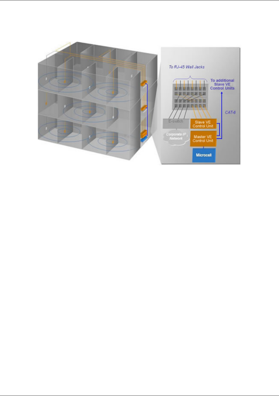
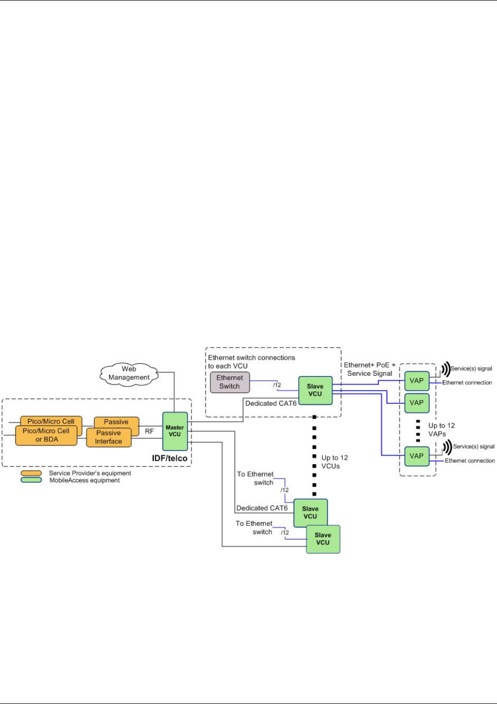
The following figure shows the Dual Band EnCOVER VE™ solution architecture (multi-tier).
Figure 3. EnCOVER VE™ Multi-Tier Basic Architecture
The Master VCU distributes the wireless services from the service provider’s equipment to the
Slave VCUs. At the Slave VCUs, the wireless services are converged with Ethernet service and
routed to the VAPs via the Ethernet LAN CAT-5e/6 cabling infrastructure.
The VAPs distribute the wireless services via integrated internal antennas or external antennas
(optional VAP models) and provide Ethernet connectivity to the LAN terminals.
1.2 System Elements
This chapter describes the interfaces of the EnCOVER VE™ Control Units and Access Pods.
1.2.1 EnCOVER VE™ Control Unit (VCU)
Capabilities and interfaces
The EnCOVER VE™ Control Unit can operate as a Master VCU, managing up to 12 VCUs OR as a
Slave VCU connected to up to 12 VAPs.
While operating as a Master VCU:
• Interfaces to RF source(s) and to VCUs
• Converges Wireless services and distribution to Slave VCUs
• Slave VCUs and VAP management and control – Locally
• Remote management
While operating as a Slave VCU:
• Interfaces to Master VCU
• Converges Wireless services, Ethernet and PoE and interfaces to VAPs
• Connected VAPs management and control
Overview
Dual Band EnCOVER VE™ Instant Coverage Solution User Manual 4
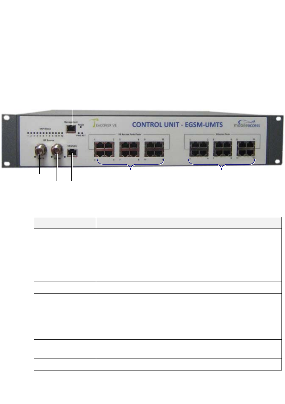
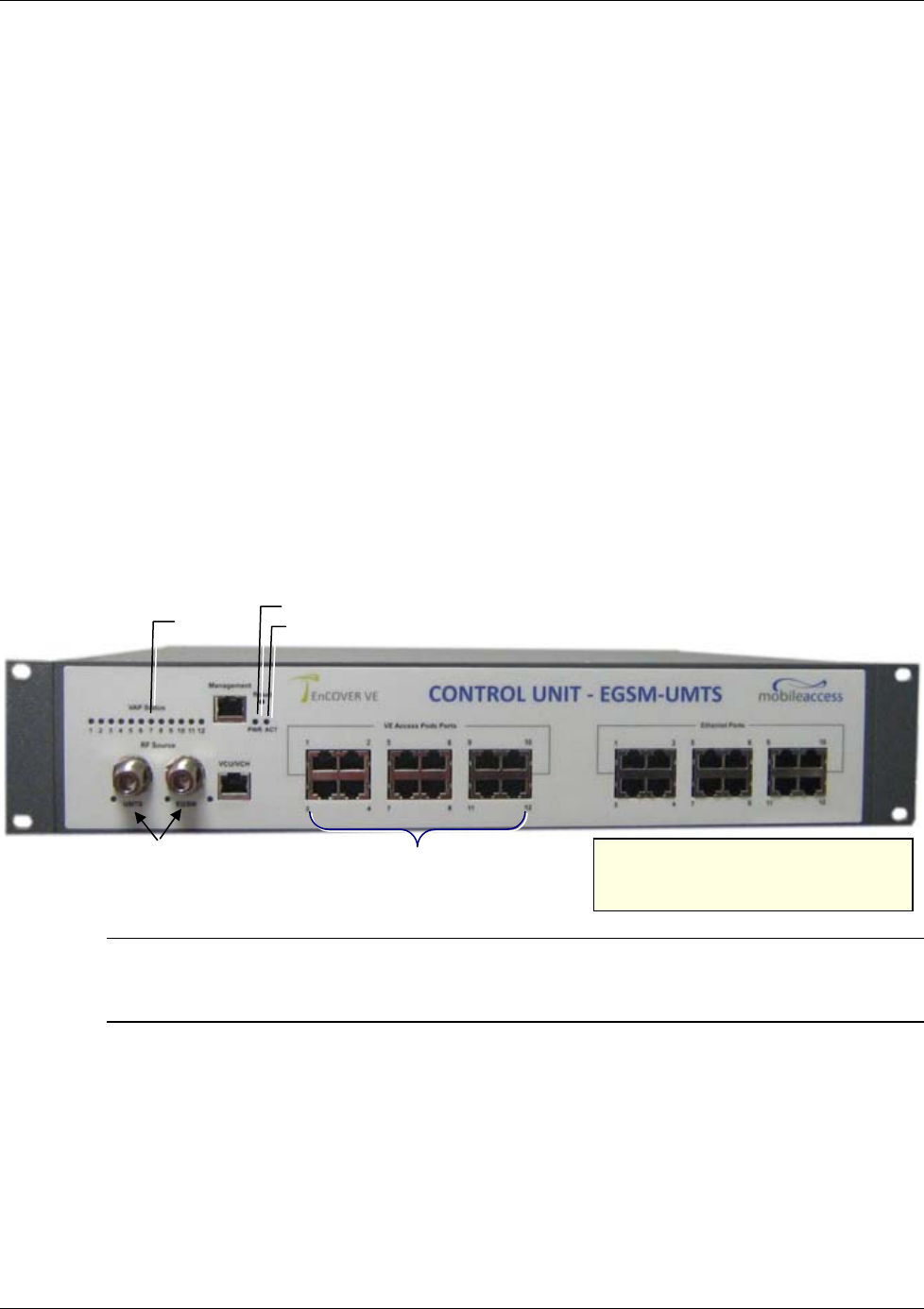
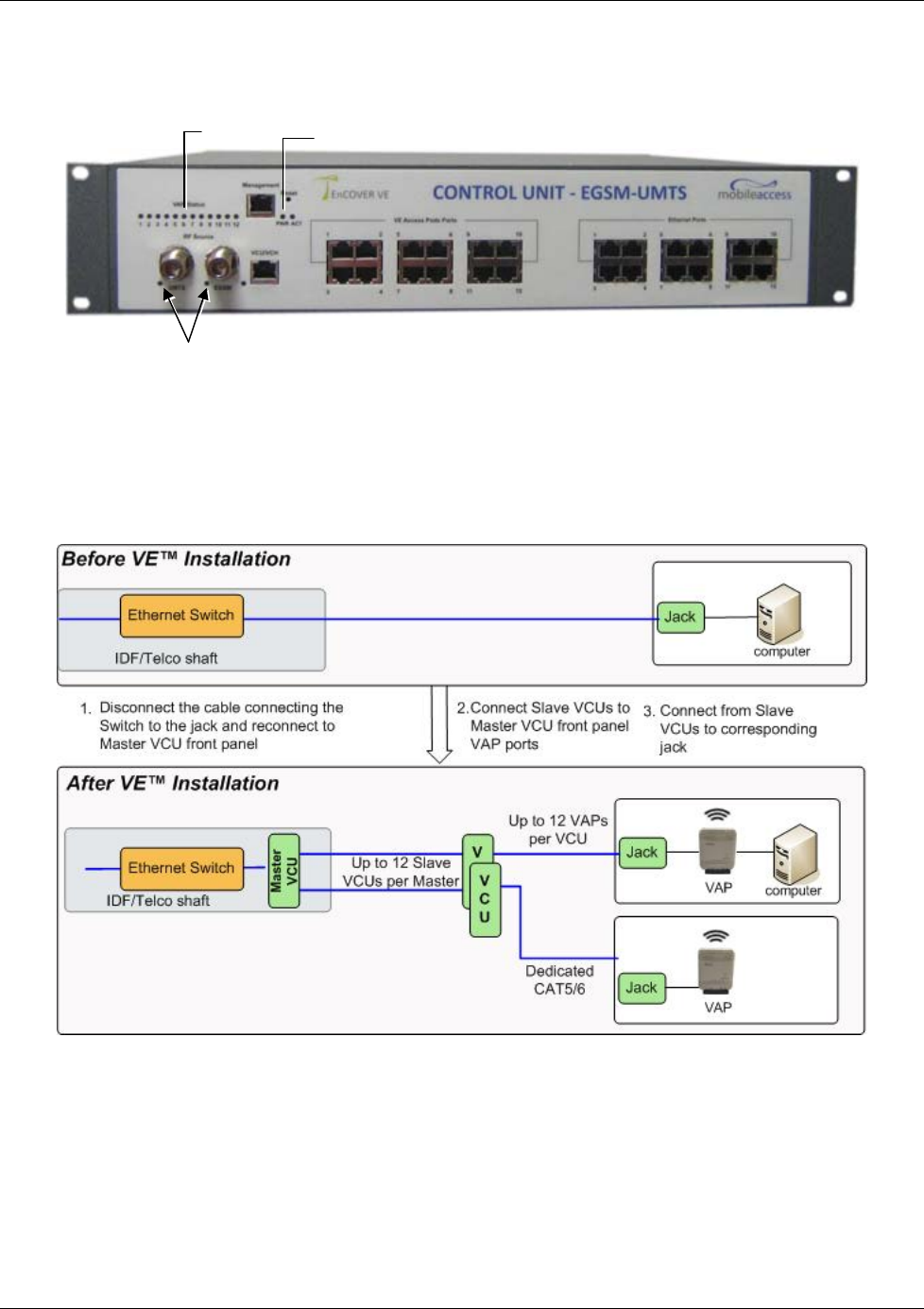
1.2.1.1 VCU Front Panel
The front panel supports the interfaces to the wireless services (two services – corresponding to
the two supported bands) and includes the VAP interfaces (that can also serve as Slave VCU
interfaces in Master/Slave VCU configuration). The front panel also interfaces to the Ethernet
switch, includes two connectors for receiving the wireless services from the Master VCU and the
management interface. Control and management interfaces.
The following provides the front panel ports.
Figure 4. VCU Front Panel
Table 1: VCU Ports Description
Ports Description
Service1
Service2 RF connections (two wireless services) to the service provider RF
equipment (e.g. picocells). Coax cables.
• EGSM-UMTS: Service 1 - UMTS, Service 2 - EGSM
• CELL-PCS: Service 1 - PCS, Service 2 – CELL
• DCS-UMTS: Service 1 – UMTS, Service 2 - DCS
Management RJ45 WEB management connection.
VE Access Pod Ports
1-4; 5-8; 7-12 VAP/VCU port connections (depending on whether the unit is
functioning as a VCU or Master VCU). RJ-45 connection to VAP/VCU
through the LAN infrastructure. CAT-5e/6 cables.
Ethernet Ports 1-4;
5-8; 7-12 Ethernet port connections to Ethernet Switch. Ethernet cables.
VCU/VCH Used for connecting a Slave VCU to the Master VCU in a multi-tier
deployment
Reset N/A
Ethernet Ports 1-4; 5-8; 7-12
VAP Ports 1-4; 5-8; 7-12
Management
Service 2
Service 1
V
CU/VCH
Port
Overview
Dual Band EnCOVER VE™ Instant Coverage Solution User Manual 5
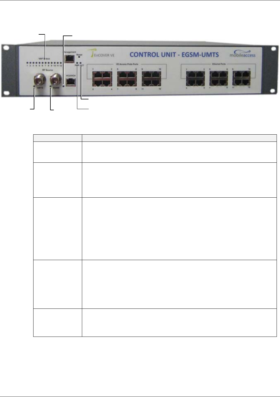
The following provides a description of the front panel LEDs.
Table 2: VCU LEDs Description
LED Description
PWR Indicates whether the VCU receives power:
Green - Power OK
Disabled - No power received by VCU
ACT VCU activity LED:
Solid Green – during initialization
Blinking Green – normal system operation
Solid Orange – VCU is faulty
Fast Blinking Green – User activated
VCU Identify
on this VCU
VAP Status (one
LED per port) Indicates the status of the connected unit (VAP or VCU)
Disabled – no power supplied to corresponding unit
Blinking Green - associated unit is initializing
Solid Green - associated unit is in normal operation
Solid Orange - associated unit is faulty, or connected unit is not managed
(due to mismatch type, VoIP phone, VCU connected to a slave VCU etc.)
Fast Blinking Green – User invoked “identify” command on the
corresponding unit
Off – when there is no VAP or VCU connected to this port.
RF (one LED per
Service) Indicates the status of connected RF capacity source:
Green – Relevant only when VCU is the Master and indicates normal RF
level
Orange - Relevant only when VCU is the Master and indicates that the RF
level is either too low or too high, or that the service has been turned off
by the user.
Off - When VCU is a slave unit
VCU/VCH Indicates the status of the connection to the Master VCU:
Off – when in Master mode
Blinking Green – During Attachment process with upper VCU Master
Solid green - when in Slave (IF-IF) mode and adjustment alarm is clear
PWR
A
CT
VAP Status
LEDs
V
CU/VCH LED
Service
LED Service
LED
Overview
Dual Band EnCOVER VE™ Instant Coverage Solution User Manual 6
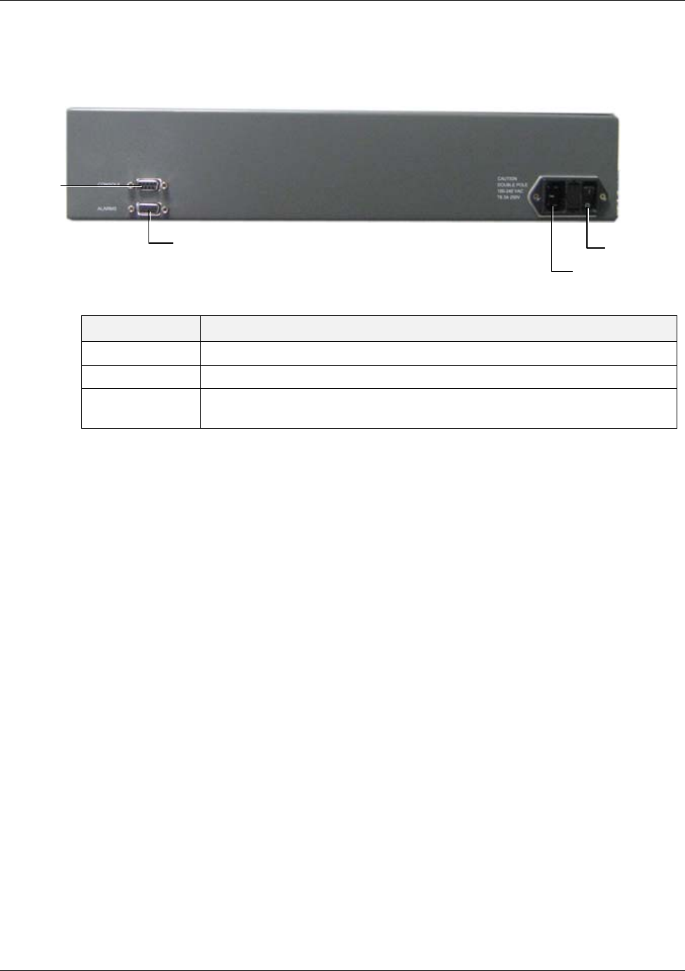
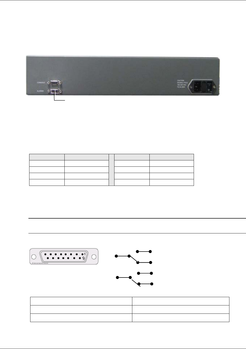
1.2.1.2 VCU Rear Panel
The rear panel includes the power input, the AUX alarms and service personnel connections.
Figure 5. VCU Rear Panel
Table 3: VCU Rear Panel Description
Connector Description
Console RS232 local connection for service personnel
Alarms AUX alarms connections - see 4.2
Power Input Standard 3-pins AC power connector equipped with an ON/OFF switch.
90-264V AC, 47-63 Hz AC; 350W power consumption maximum.
PWR On/Off
switch
A
C connector
A
UX Alarms
Console
connecto
r
Overview
Dual Band EnCOVER VE™ Instant Coverage Solution User Manual 7
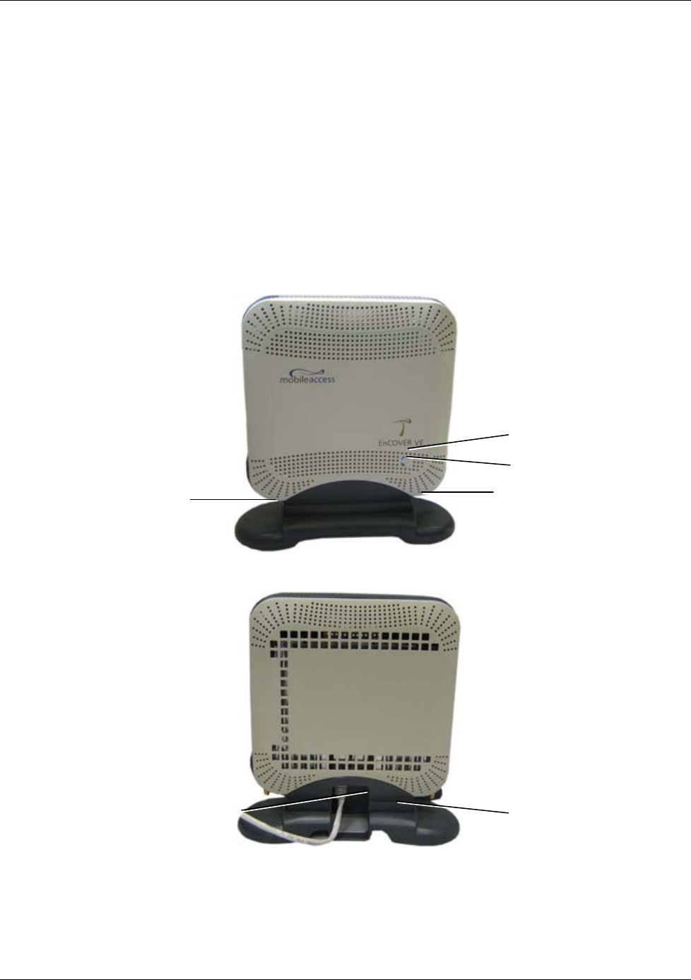
1.3 EnCOVER VE™ Access Pod (VAP)
Each VAP provides the following functions:
• Antenna – distributes the wireless services signals. The antenna is internal, where an
external (optional) antenna can also be connected (in models supporting external antenna).
• Connection to Ethernet port – relevant when connected to jacks that provide an Ethernet
connection to a user terminal.
The VAP can be mounted/hung on the wall or placed on a flat surface (such as a desk).
The following figure shows the desktop VAP and the underside view with the CAT-5e/6 patch-
cord cable.
Figure 6. EnCOVER VE™ Access Pod-Front
Figure 7. EnCOVER VE™ Access Pod-Rear
RJ-45 Connector to LAN
terminal (e.g. computer)
RJ-45 Connector to VCU
Blue LED (Activity)
Green Led (Power)
Optional External Antenna
SMA connector
Optional External Antenna
SMA connecto
r

Overview
Dual Band EnCOVER VE™ Instant Coverage Solution User Manual 8
Figure 8: VAP LEDs
LED Description
Power Solid Green - Power supplied to VAP
Off - No power supplied to VAP
Activity Disabled - No power supplied to VAP or faulty VAP
Blinking Blue - Power on, VAP is initializing or in a fault condition
Solid Blue - Power on, RF signal received, unit operating
Fast Blinking Blue - User invoked “identify” command on corresponding VAP
1.3.1 VAP Types
Two types of VAPs are available:
• VAP with internal antenna
• VAP with connector that interfaces to external antenna (for special coverage requirements)
The antenna type (internal or external) is automatically detected by the system so there is no
need for specific configuration. Each VAP can only transmit through the provided antenna option.
For example, if the VAP includes an external antenna connector the signal is only transmitted via
the external antenna connector.
1.3.2 System Monitoring and Management
The EnCOVER VE™ system (Master VCU, Slave VCUs and VAPs) is centrally managed via a single
Web connection to the Master VCU.
The basic screen in the GUI is the monitor tab which enables the user to view the system
topology and setup parameters, the Control Units and all of the Access Pods that are connected
to the Control Units.
Note: When locally connecting to a specific VCU, only the VAPs connected to this VCU can be
monitored.
1.3.2.1 Integration with an External Fault Management System
The EnCOVER VE™ system can be seamlessly integrated into any existing Fault Management
(FM) system that supports SNMP events. The Master VCU generates SNMP event for each
relevant system alarm and forwards this trap to the pre-configured IP address of the external
Fault Management system.
Installation Workflow
Dual Band EnCOVER VE™ Instant Coverage Solution User Manual 9
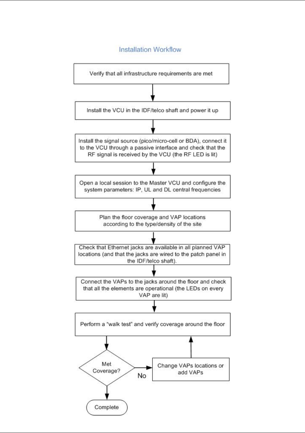
2 Installation Workflow
The following figure summarizes the main steps of the installation procedure:
Infrastructure Requirements and Layout Planning
Dual Band EnCOVER VE™ Instant Coverage Solution User Manual 10
3 Infrastructure Requirements and Layout
Planning
3.1 General information on Location and Connections
• Service provider’s RF equipment - Macro-cell, Micro-cell, Pico-cell, Femto-cell, BDA, etc.
connects to the VCU through a passive interface.
• VCUs:
• Master VCU installed at the main IDF/telco cabinet and connected to al VCUs.
• Slave VCUs installed at the IDF/telco cabinet of each covered floor and connected to
the cabling patch panel.
• Wireless service signal from Master VCU to VCUs – routed through dedicated Ethernet
CAT-6 or 7 cabling.
• Wireless service signal from VCUs to the VAPs – routed through existing Ethernet CAT-
5e/6 cabling infrastructure.
• VAP location and mounting - wall-mounting or desk-mounting. Connection to existing
Ethernet jack (and external antenna if required).
• VAP power source - No power connections required. VAPs are power fed from VCU using
PoE (Power over Ethernet) technology.
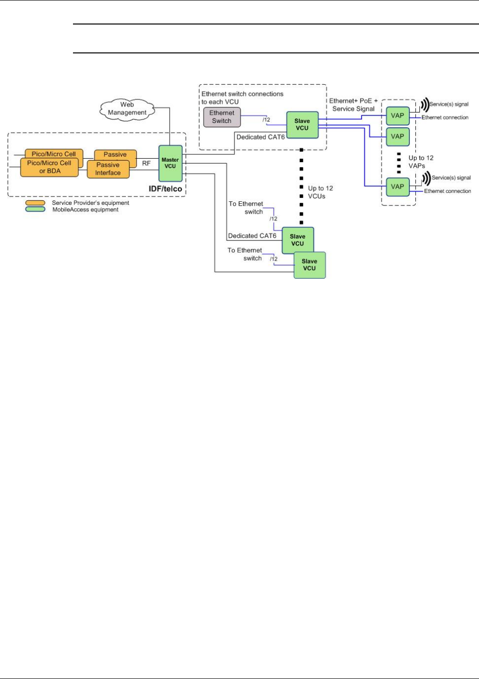
Figure 9. EnCOVER VE™ Multi-Tier Basic Architecture

Infrastructure Requirements and Layout Planning
Dual Band EnCOVER VE™ Instant Coverage Solution User Manual 11
3.2 Infrastructure Requirements
1. IDF/Telco closet space for one or more VCUs depending on the number and locations of the
installed VCUs: (48.3 x 51.3 x 8.88 cm) per VCU.
Note: When planning the IDF/telco shaft, take the RF equipment (pico-cell/micro-cell or
BDA) and the VCU in to consideration.
2. 350 Watts of AC power to the VCU IDF/Telco closet.
3. Building infrastructure:
• Category 5e or CAT-6 cabling, Unshielded or Shielded Twisted Pair (UTP/STP)
• 24 AWG minimum diameter for CAT-5e cabling
• Dedicated CAT-6/7 STP cable from Master VCU to Slave VCUs with run lengths NOT
exceeding 100m (300ft).
• CAT-5e/6 UTP or STP cable from VCU to each VAP with run lengths NOT exceeding
100m (300ft). VAPs can be connected over existing CAT-5e/6 cabling infrastructure and
existing Ethernet jacks without affecting the LAN.
4. Master VCU Cable Connections:
• 2 x N-type female, 50 ohm interfaces to carrier equipment
• Up to 6 x RJ-45 interfaces to VCUs
• 1 x RJ-45 interface to Management
• 1 x D-Type 9 pins RS-232 interface for local craft
• 1 x D-Type 15 pins interface for External Alarms (dry contacts)
5. Slave VCU Cable Connections
• 1 x RJ-45 interface to Master VCU (not used in small single tier deployments)
• 12 x RJ-45 interfaces to VAPs
• 12 x RJ-45 interfaces to Ethernet Switch for LAN service “bridging”
• 1 x D-Type 9 pins RS-232 interface for local craft

Infrastructure Requirements and Layout Planning
Dual Band EnCOVER VE™ Instant Coverage Solution User Manual 12
3.3 Coverage and Installation Planning
Note: The following section provides the information required for planning the VAP installation
on a single floor. In a multi-tier installation, this procedure is performed for each floor
separately.
The maximal coverage area of each VAP is affected by the density and type of environment to
be covered. Therefore, it is recommended to determine the location in two phases:
• Plan the
ideal
location of each VAP in order to achieve complete coverage of the floor and
then
• Select
exact
location according to the location feasibility, where each VAP unit may be
mounted on a wall or placed on a desk and an option for an external antenna is available
(for specific VAP models).
The supplied services (wireless only or Ethernet and wireless) depend on the jack to which the
VAP is connected:
• If the jack supports an active Ethernet connection – the VAP will distribute LAN traffic along
with the wireless service. For more information see section 4.3.1.
• If the jack is not currently active (not connected to an Ethernet switch) - the VAP will
distribute only the wireless services.
This section provides information on coverage criteria in various types of environments (Open,
Standard, Dense and Merged) and provides rules-of-thumb for various installations of the VAPs.
Note: Section
3.4 provides a detailed example of installation planning in various types of
environment. It is recommended to review this example after reading this section.
3.3.1 Types of Environments
This section describes the different types of installation environments and provides guide lines
for best coverage of each type of space.
The coverage guidelines in this section are conservative “rule of thumb” estimates of RF
coverage per VAP, meant to be used in scenarios in which detailed designs are not performed.
When the coverage layout is designed, the coverage per VAP is expected to increase by up to
33%. Coverage estimates in this section assume 25% overlap between the coverage areas of
neighboring VAPs to ensure robust, full coverage throughout the enterprise with no “dead
zones”.
The coverage guidelines in the following tables are provided for the
higher
frequency bands
(UMTS & PCS). The lower frequency bands (DCS, EGSM & CELL) are omitted from the tables
since coverage in these bands will be better than that of the higher frequency bands. The
coverage of a dual-band system will be determined by the higher frequency band (i.e. PCS for
CELL/PCS and UMTS for EGSM/UMTS and DCS/UMTS).

Infrastructure Requirements and Layout Planning
Dual Band EnCOVER VE™ Instant Coverage Solution User Manual 13
3.3.1.1 Open environment
An environment with minimum of obstacles (such as walls). This type of space can be a large
conference or meeting room, cubical areas, lobby or atrium areas.
Table 4: Open Environment Installation Distances
Band and Technology PCS (CDMA or GSM) PCS (WCDMA) UMTS (WCDMA)
Downlink Frequency 1900 MHz 1900 MHz 2100 MHz
Signal Propagation from VAP 90 feet
(27 m) 83 feet
(25 m) 67 feet
(21 m)
Recommend spacing between VAPs 180 feet
(54 m) 166 feet
(50 m) 134 feet
(42 m)
Recommended maximum distance of
VAPs from outer walls 90 feet
(27 m) 83 feet
(25 m) 67 feet
(21 m)
Coverage Area per VAP 25,425 sqft
(2,362 sqm) 21,375 sqft
(1,986 sqm) 14,250 sqft
(1,324 sqm)
3.3.1.2 Standard Environment
A traditional office environment with offices, hallways and scattered cubicles.
Table 5: Standard Environment Installation Distances
Band and Technology PCS (CDMA or GSM) PCS (WCDMA) UMTS (WCDMA)
Downlink Frequency 1900 MHz 1900 MHz 2100 MHz
Signal Propagation from VAP 67 feet
(21 m) 64 feet
(19 m) 58 feet
(18 m)
Recommend spacing between VAPs 134 feet
(42 m) 128 feet
(38 m) 116 feet
(36 m)
Recommended maximum distance of
VAPs from outer walls 67 feet
(21 m) 64 feet
(19 m) 58 feet
(18 m)
Coverage Area per VAP 14,250 sqft
(1,320 sqm) 12,750 sqft
(1,185 sqm) 10,425 sqft
(969 sqm)

Infrastructure Requirements and Layout Planning
Dual Band EnCOVER VE™ Instant Coverage Solution User Manual 14
3.3.1.3 Dense Environment:
A dense environment consists of a relatively large amount of walls, offices, equipment, tall file
cabinets, bookshelves and other items that could potentially impact the wireless signal.
Examples for this type of environment are dense offices, hospitals and manufacturing spaces.
Table 6: Standard Environment Installation Distances
Band and Technology PCS (CDMA or GSM) PCS (WCDMA) UMTS (WCDMA)
Downlink Frequency 1900 MHz 1900 MHz 2100 MHz
Signal Propagation from VAP 64 feet
(19 m) 60 feet
(18 m) 45 feet
(14 m)
Recommend spacing between VAPs 128 feet
(38 m) 120 feet
(36 m) 90 feet
(28 m)
Recommended maximum distance of
VAPs from outer walls 64 feet
(19 m) 60 feet
(18 m) 45 feet
(14 m)
Coverage Area per VAP 12,750 sqft
(1,185 sqm) 11,250 sqft
(1,045 sqm) 6,300 sqft
(585 sqm)
3.3.1.4 Combination of Environments
In areas with combinations of environments of various densities, place the VAPs on the border
between the different types of areas – closer to the denser area.
For example, in a cubical area with the outside wall having offices, simply locate the VAPs a little
closer
to the outside offices
to provide coverage through the office walls. (See VAPs 11 and 13 in
the floor plan map in section 3.4.3.)
To ensure maximal coverage, VAPs can be re-located or added. If a coverage gap is detected,
the VAPs can be re-located until the coverage gaps are filled.
3.4 Planning VAP Layout
The following section describes the steps of planning the VAPs along the covered floor. At the
end of this section an example of a planning map is provided.
Note: It is highly recommended to use a floor plan when planning the VAPs locations.
3.4.1 RF Coverage Factors
It is important to note the type of factors that can severely impact RF coverage which should be
avoided:
• Metallic structures such as elevators, high file cabinets and some moveable metallic
partitions severely degrade RF signal and all efforts should be made to locate VAPs in front
of or above metallic objects (desks, filing cabinets) to allow the signal to propagate.
• Wall materials such as concrete, tile and cinderblock along with bathroom fixtures typically
have fairly high signal attenuation and should be considered as dense spaces.

Infrastructure Requirements and Layout Planning
Dual Band EnCOVER VE™ Instant Coverage Solution User Manual 15
• Types of glass (typically exterior or mirrored) that have metallic coatings on it which can
affect RF coverage, however that is typically not encountered inside a building.
3.4.2 Mapping Locations
To map the VAP Locations
1. Map out the available Ethernet jack locations: mark all the CAT-5e/6 drops locations on the
floor plan map.
TIP: The size and number of the ceiling tiles can be used to measure distances.
2. Using the floor plan and the VAPs coverage guidelines (as given in section 3.4.3) mark
approximately where you would like to place each VAP in the facility.
VAPs may be added (or removed) at anytime for optimal coverage.
3. For each jack to be used for connecting a VAP, check if the jack is already connected to the
Ethernet switch (via the patch panel). Record the connections for each jack, for reference.
4. Connect the Ethernet cables corresponding to the selected jacks as follows according to
section 4.3.1.
5. It is also recommended to check the area in which the VAPs are to be installed and make
sure that the installation is feasible.
3.4.3 Optional Directional Antennas
Each VAP has an integrated internal antenna that provides isotropic radiation. To prevent
interference and improve coverage, you may connect directional antennas to VAPs (ordered with
the external antenna option) installed near outer walls (the VAP antenna parameter must be set
accordingly via the Web GUI – see 6.3.6.2).
Infrastructure Requirements and Layout Planning
Dual Band EnCOVER VE™ Instant Coverage Solution User Manual 16
3.4.4 Installation Plan Example
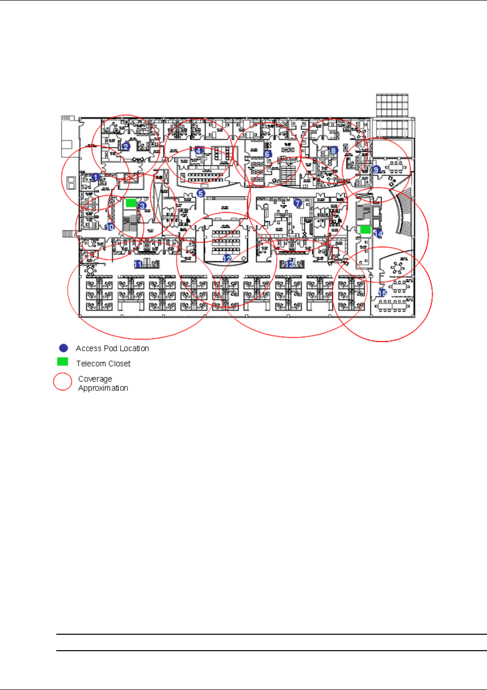
The Following figure shows a floor plan map with all required marks:
Figure 10. Floor Plan Example
Notes:
• The red VAP coverage circles are approximately 45, 58 and 67 foot (14, 18 and 21 m) radius
for the small, medium and large circles respectively (drawn according to the guidelines for
UMTS service, given in section 3.3.1).
• VAP 3 is surrounded by dense objects, the bathroom and stairwell which would reduce
coverage in that area by the other VAPs.
• VAP 5 is an example of a unit that provides good coverage down the hallways.
• VAPs 11 and 13 are placed closer to the offices to cover them well but on the open side will
actually cover a much greater area which is why the coverage is larger and shown here
more as an oval than a circle.
• The area between VAPs 7 and 14 outside the bathrooms would probably be the lowest
coverage spot in the building because of the bathrooms and stairwell on either side of that
area. If after the system installed, this area is still a little low on coverage, a VAP can be
added, but it may also be covered by VAP 14.
Note: The plan can be modified at any time by moving the units around or by adding units.
Infrastructure Requirements and Layout Planning
Dual Band EnCOVER VE™ Instant Coverage Solution User Manual 17
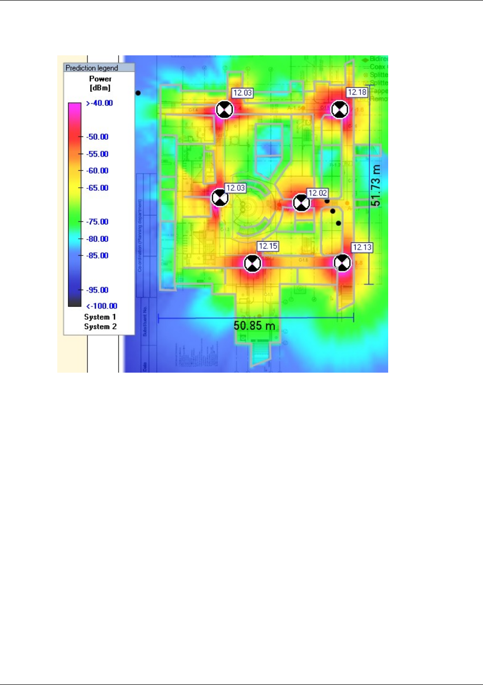
The following figure depicts an actual measured quantified coverage of a floor area planed
according to the above rules
Figure 11. Distributed VAPs propagation, 12dBm output power @ 1.8GHz
VCU Unit Installation and Configuration
Dual Band EnCOVER VE™ Instant Coverage Solution User Manual 18
4 VCU Unit Installation and Configuration
This section describes the installation and configuration procedures of the EnCOVER VE™ Control
Unit (VCU) in each floor. These should be performed only after planning the floor coverage and
installation locations as described in the previous sections.
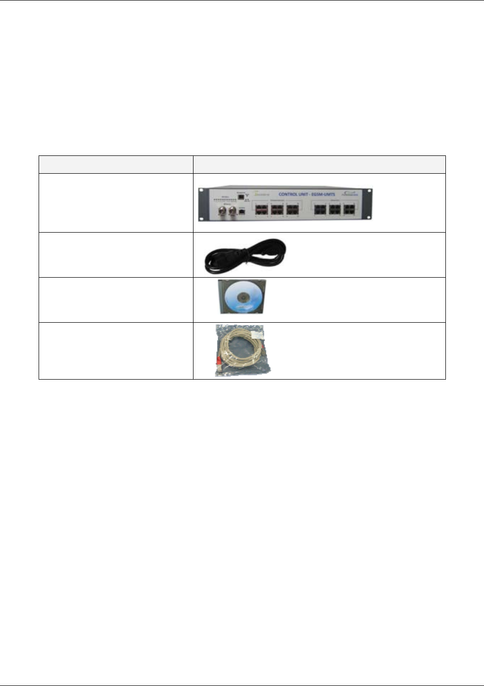
The EnCOVER VE™ VCU kit includes:
Table 7: VCU Kit
Description Unit
Dual Band EnCOVER VE™ Control
Unit (VCU) kit
Power cord
EnCOVER VE™ SW CD
Local configuration cable (crossed
RJ-45 cable)
VCU Unit Installation and Configuration
Dual Band EnCOVER VE™ Instant Coverage Solution User Manual 19
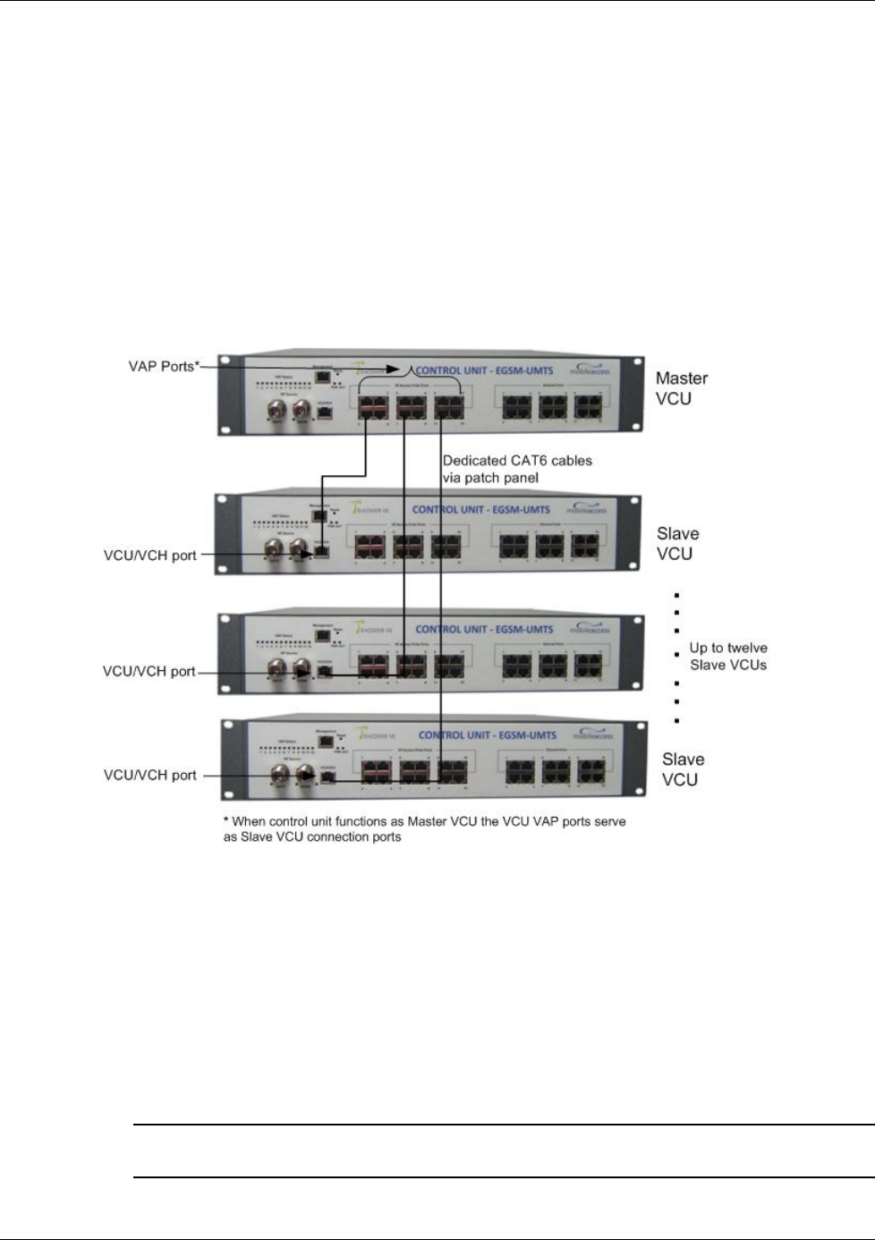
4.1 EnCOVER VE™ Control Unit Installation as a Master
VCU
The EnCOVER VE™ control unit can be installed as a Master VCU and control up to 12 Slave
VCUs. The Master VCU is installed in the main IDF/telco closet. This section describes the Master
VCU installation procedure.
1. Install the Master VCU in the main IDF/Telco closet. The Master VCU can be installed in the
rack or on the wall using the optional wall mount bracket in the IDF closet along with the
provider’s signal sources.
2. Connect the Master VCU VAP ports to the Slave VCUs Expansion ports via the patch-
panel that feeds the dedicated CAT-6 or 7 cabling system.
3. Connect (or request the service provider’s service personnel to connect) the provider’s
signal source (Macro-cell, Micro-cell, Pico-cell or BDA) to the Master VCU front panel RF
ports (through passive interface).
4. Apply power to the Master VCU and note that the PWR LED is lit.
5. Power on the signal sources (for example EGSM and UMTS BTSs) and note that the unit ACT
LED completes initialization (blinking light) and shows a solid green light.
NOTE: After the Slave VCUs are connected (according to section
4 ), verify that that the Master
VCU VAP Status LEDs, corresponding to the connected Slave VCUs, complete initialization
(blinking light) and show a solid green light.
RF ports Note: When functioning as a Master VCU,
the control units’ Ethernet Ports are
not relevant.
VAP Ports 1-4; 5-8; 7-12
PWR LED
A
CT LED
V
AP Status
LEDs
VCU Unit Installation and Configuration
Dual Band EnCOVER VE™ Instant Coverage Solution User Manual 20
4.2 Auxiliary Connections
The auxiliary connections are performed through the Master VCU rear panel Alarms port. See
following figure.
4.2.1 Auxiliary Input Connections
This Auxiliary connector can be used to monitor up to eight auxiliary connections such as fire-
alarm, air-conditioning alarm, open-door alarm, etc. The connections are normally open.
Connect the relevant alarms according to the connector pinout described in the following table.
Table 8. Auxiliary Connector
Pin Number Auxiliary Alarm Pin Number Auxiliary Alarm
1, 26 8 8, 9 4
2, 3 7 10, 11 3
4, 5 6 12, 13 2
6, 7 5 14, 15 1
4.2.2 Alarm Output Connections
The controller can provide Major and Minor output alarms. These alarms can be connected
directly to the auxiliary input of the Base Station, or to any other dry-contact application.
Note: If only one alarm is required (Minor or Major) an external connection of a wire jumper
between pins 8 and 13 is necessary (normally closed)
Connect the relevant alarms according to the connector pinout below.
Table 9. Alarms Connector – used pins
8 – Major Error signal (normally closed) 7 – Minor Error signal (normally open)
11 – Major COM 12 – Minor COM
15 –Major Error signal (normally open) 13 – Minor Error signal (normally closed)
11 15
8 Major Alarm
12 7
13 Minor Alarm
A
larms port for auxiliary
connections
VCU Unit Installation and Configuration
Dual Band EnCOVER VE™ Instant Coverage Solution User Manual 21
4.3 EnCOVER VE™ Control Unit Installation as a Slave
VCU
1. Install the EnCOVER VE™ Slave Control Unit (VCU) in the IDF/Telco closet corresponding to
the floor to be covered. The Slave VCU can be installed in the rack or on the wall using the
optional wall mount bracket in the IDF closet.
2. Connect the Slave VCU VAP ports to the patch-panel that feeds the existing structured CAT-
5e/6 cabling system.
3. Connect the Slave VCU front panel VCU/VCH port to the Master VCU VAP port via the
patch panel using dedicated CAT6 cables.
4. According to VAPs layout plan (as explained in section 3.4.2) connect the Ethernet switch
cables (see section 4.3.1 for more detailed explanation):
• If the jack to be used is already in use (connected to Ethernet switch) – disconnect it from
the Ethernet switch and re-connect it to the corresponding Ethernet port in the Slave VCU
front panel.
• Jacks not in use will be connected only to the Slave VCU.
5. Request the service provider’s service personnel to connect the provider’s signal source (e.g.
UMTS Node B, GSM BTS, etc.) to the RF ports on the Master VCU front panel, through
passive interface.
Note: The RF Source LED (see following figure) of the connected port on the Master VCU
should be lit, indicating that the Master VCU senses the RF signal from the source.
VCU Unit Installation and Configuration
Dual Band EnCOVER VE™ Instant Coverage Solution User Manual 22
6. Apply power to the Slave VCUs and note that the VCU PWR LED is lit and that the VAP
Status LEDs complete initialization and show a solid light.
4.3.1 Connections of VAP Ethernet Cables
For VAPs installed on currently ACTIVE Ethernet ports - shift the relevant Ethernet LAN
connections as follows.
PWR LED
V
AP Status
LEDs
RF Source LEDs (one
per service)
VCU Unit Installation and Configuration
Dual Band EnCOVER VE™ Instant Coverage Solution User Manual 23
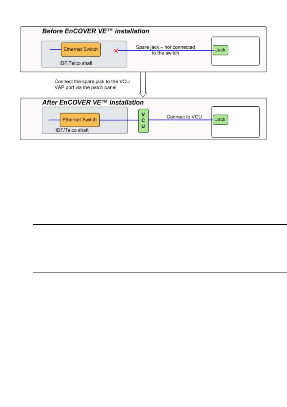
For VAPs installed on currently INACTIVE Ethernet ports – connect as follows.
4.4 Provisioning the EnCOVER VE™ Control Unit
This chapter describes how to set the basic parameters required for operation and remote
management of the Master VCU using the Web GUI. The VCU directly connected to the RF
source automatically detects itself as the master VCU and the VCUs connected to the master
VCU automatically detect themselves as slave VCUs (no special configuration required).
Notes:
1. The initial configuration of the Master VCU is performed via local connection (using a cross-
cable). After performing the initial configuration and assigning the Master VCU an IP, the
system can be connected, monitored and configured via a remote management connection.
2. The configuration and management of all of the system units (VCUs and VAPs) is performed
via the Master VCU unit (local or remote connection).
4.4.1 Configure the Computer Network Parameters
Configure the computer local LAN connection to operate in the same subnet as the default VCU
IP address. Note that the procedure may vary slightly depending on the operating system
installed on your computer. The following procedure is for Windows XP.
To configure the computer’s network parameters:
1. Click the Start menu and choose Control Panel.
2. In the Control Panel, click Network and Internet Connections.
3. Click Network Connections and then double-click Local Area Connection.
VCU Unit Installation and Configuration
Dual Band EnCOVER VE™ Instant Coverage Solution User Manual 24
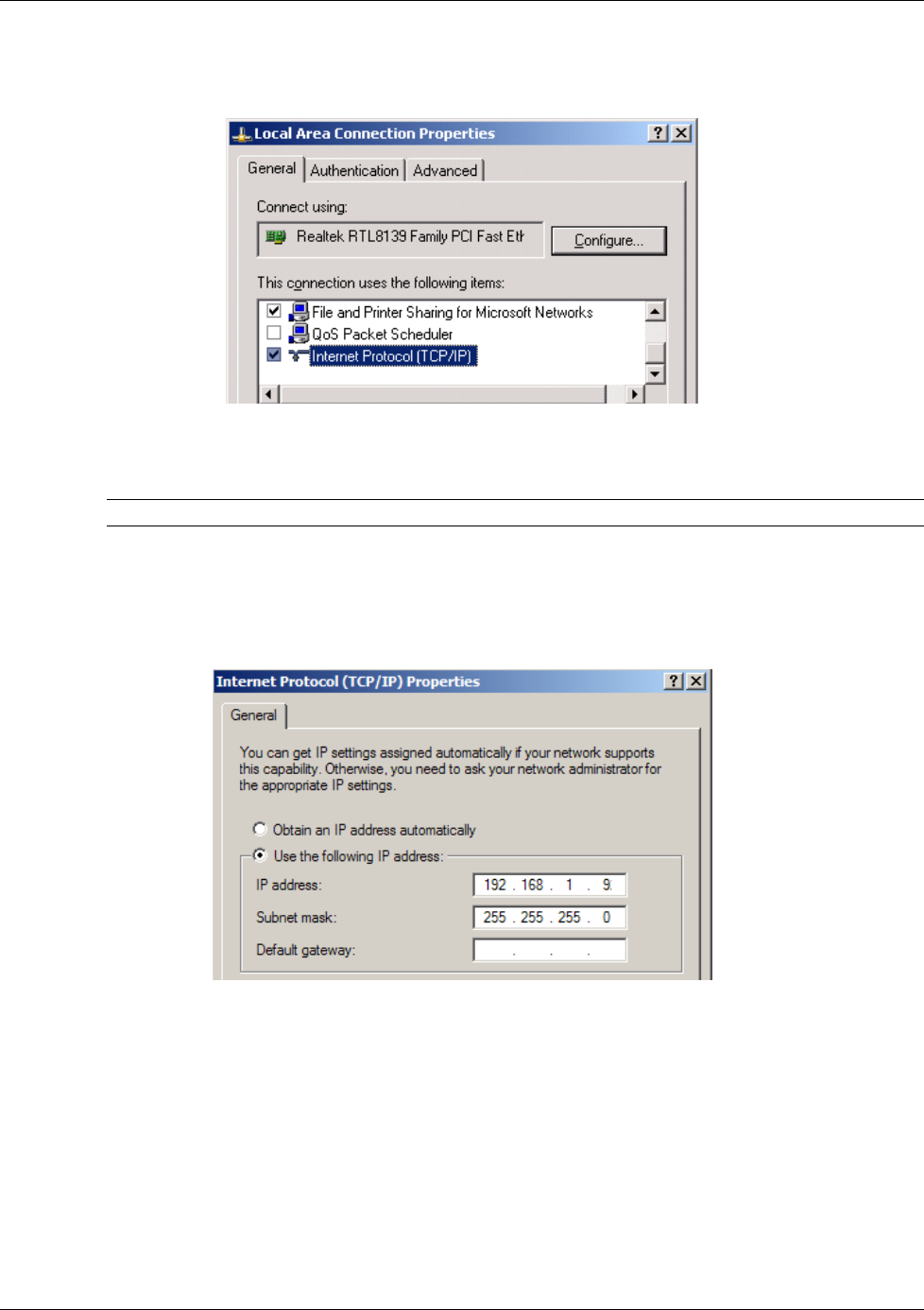
The Local Area Connections Properties dialog appears with the General tab displayed by
default.
4. In the Items list, select “Internet Protocol (TCP*IP)” and click the Properties button.
5. The “Internet Protocol (TCP/IP) Properties” dialog appears.
NOTE: The Master VCU is supplied with the default IP address 192.168.1.1.
• In order to communicate with the unit, it is necessary to assign your computer a
Static
IP
address in the same subnet: 192.168.1.2 to 192.168.1.250.
(i.e. 192.168.1.9 as shown in the example).
• Define the subnet mask as shown: 255.255.255.0
6. Click OK.
7. The computer communication parameters are now defined and you can open a session to
the Master VCU and provision the unit.
VCU Unit Installation and Configuration
Dual Band EnCOVER VE™ Instant Coverage Solution User Manual 25
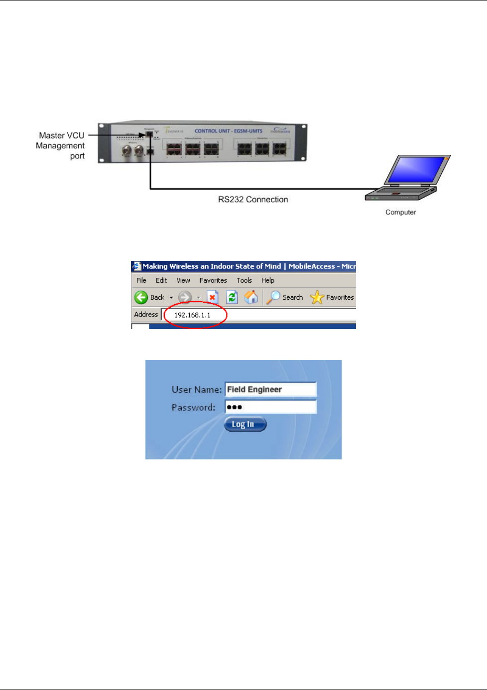
4.4.2 Provisioning the Master VCU Unit
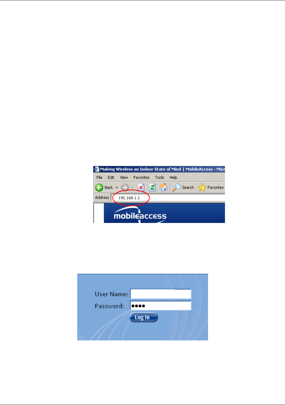
1. Perform a local connection to the Master VCU unit by connecting the Master VCU front panel
Management port and a laptop computer.
2. Open a web browser and type the Master VCU IP address in the address bar (default:
192.168.1.1).
The Login window appears.
3. Type the User Name “Field Engineer” and enter the Password “eng”.
VCU Unit Installation and Configuration
Dual Band EnCOVER VE™ Instant Coverage Solution User Manual 26
The EnCOVER VE™ Web GUI appears.
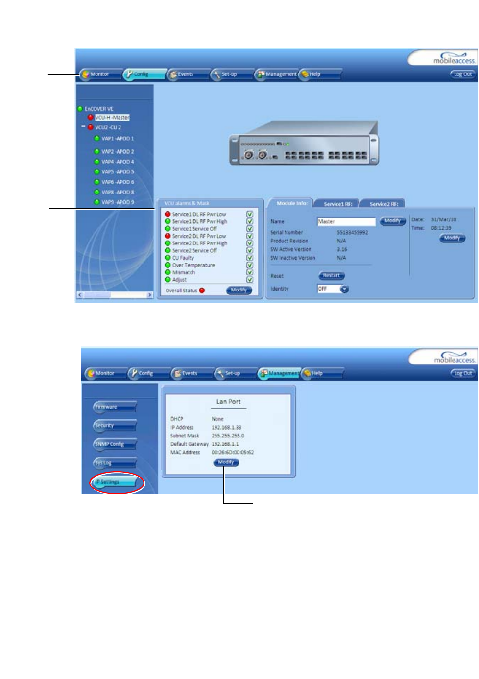
4. On the invoked application window, choose the Management tab in the main menu bar
and click the IP Settings tab on the side bar.
Networ
k
T
opology tree
Sub-tabs
that
correspond
to each
main tab
Main menu
bar
Modify button
VCU Unit Installation and Configuration
Dual Band EnCOVER VE™ Instant Coverage Solution User Manual 27
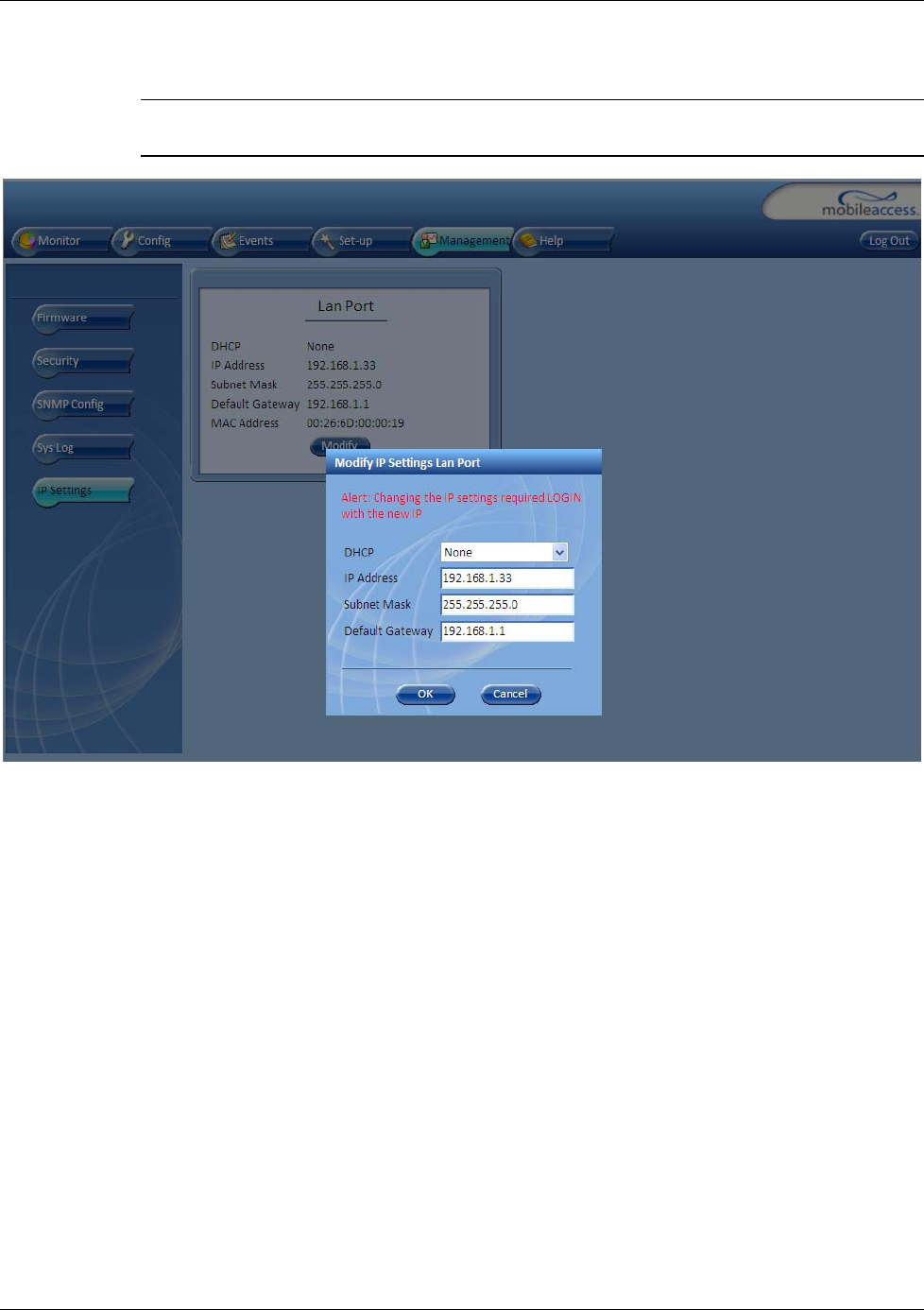
5. Click the Modify button to define the STATIC IP Address according to existing LAN.
Note: After the initial IP configuration, the Master VCU can be accessed remotely via
Ethernet.
• Set the following available parameters:
• DHCP - Dynamic Host Configuration Protocol (N/A)
• IP address - Static IP address
Default definitions:
• The Default IP Address : 192.168.1.1
• The Default Subnet Mask: 255.255.0.0
• The Default Gateway: 192.168.254.254
• Click OK.
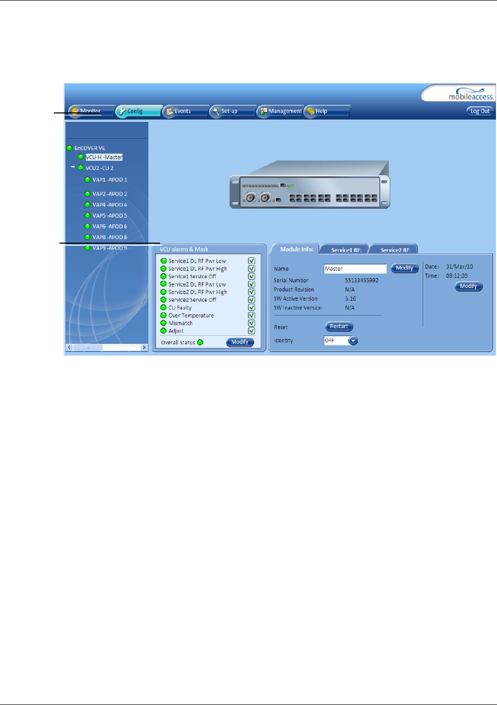
6. Log out and then log in again with the new IP settings.
7. Select the Config tab in the main menu bar.
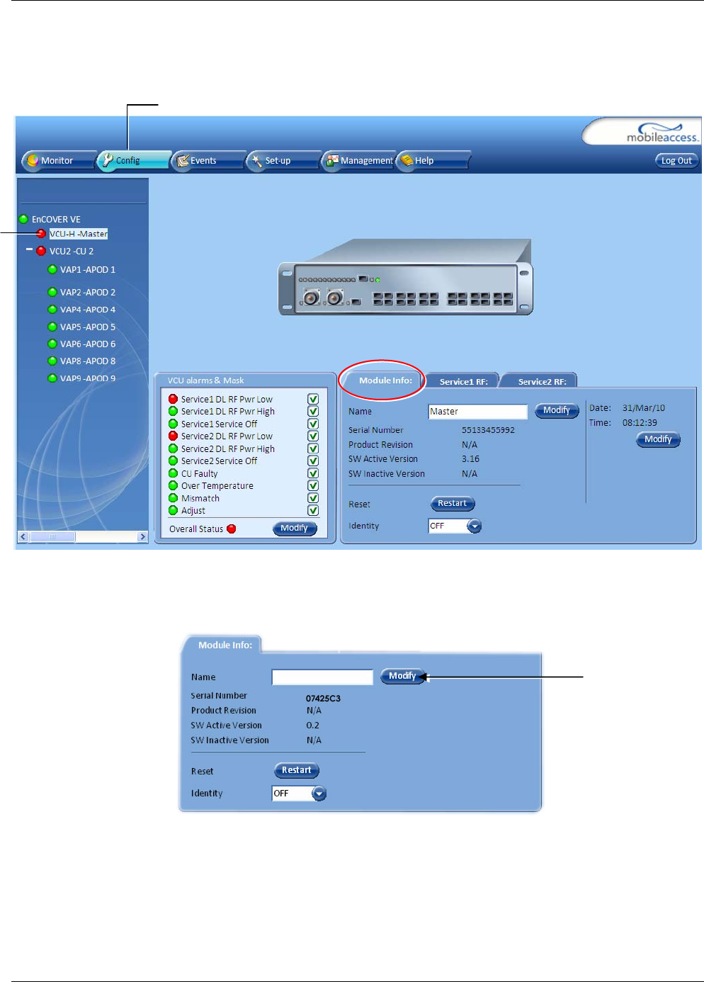
VCU Unit Installation and Configuration
Dual Band EnCOVER VE™ Instant Coverage Solution User Manual 28
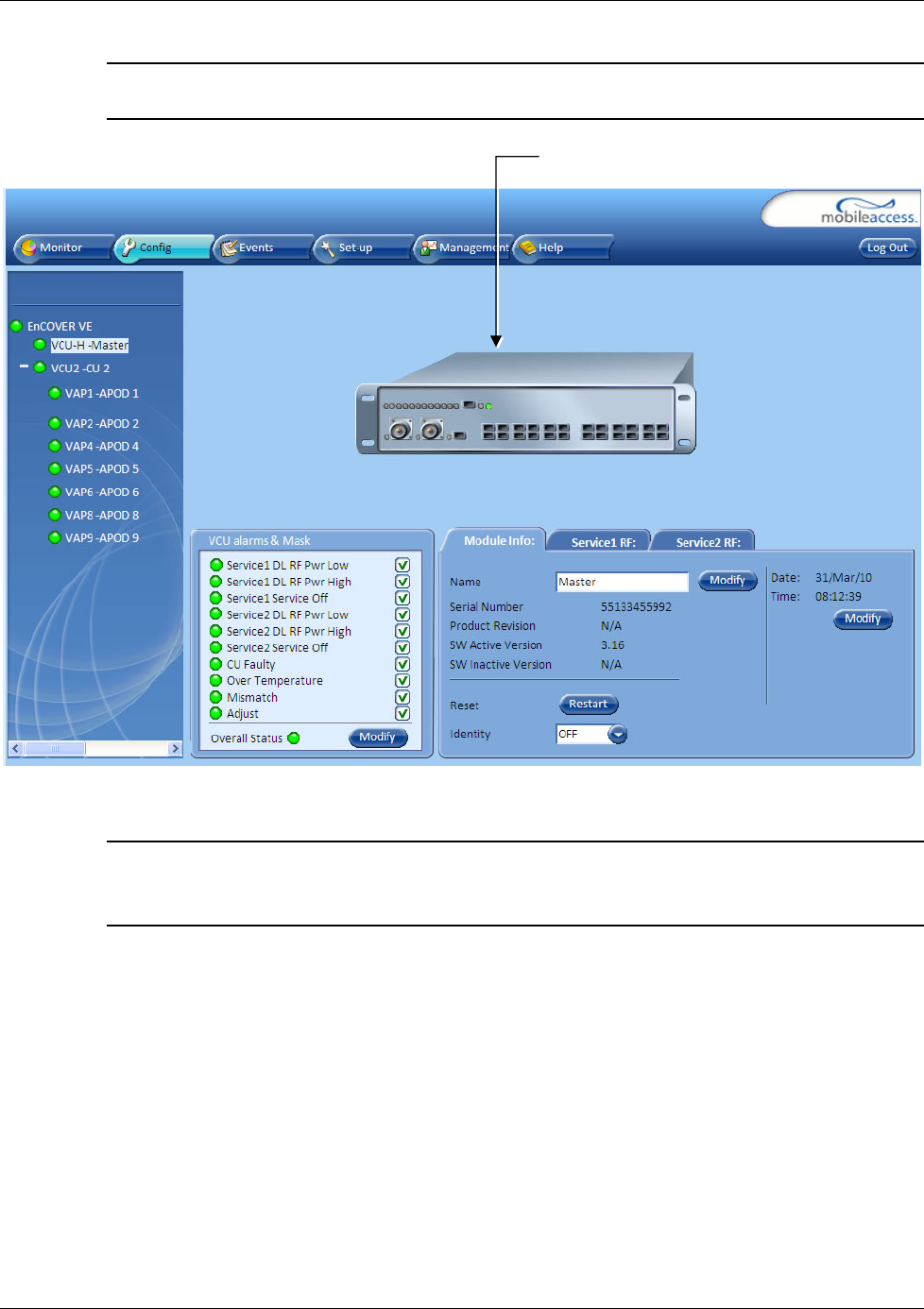
8. The Master VCU appears in the Network Topology Tree as Master VCU. Select the Master
VCU by clicking on it.
9. Before configuring the Master VCU it is recommended to give the unit an indicative name. To
assign the Master VCU an indicative name:
• Select the Module Info Tab and click the Modify button.
Click Modify
Config Tab
Master VCU
VCU Unit Installation and Configuration
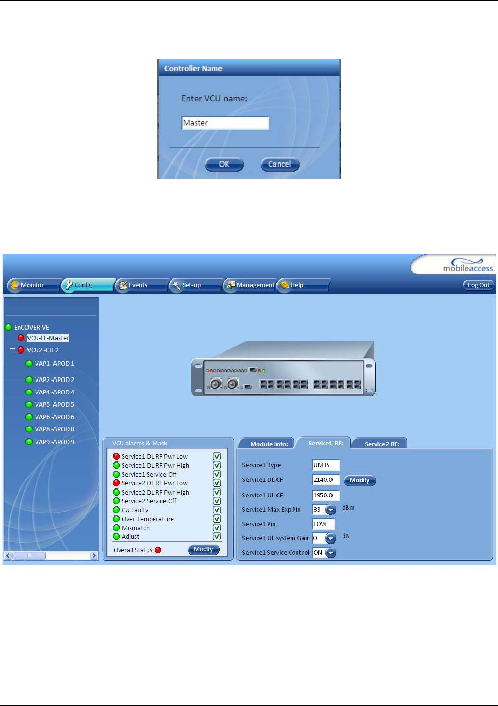
Dual Band EnCOVER VE™ Instant Coverage Solution User Manual 29
• Type the unit name (up to 20 alpha-numeric characters) in the Controller Name dialog and
click OK.
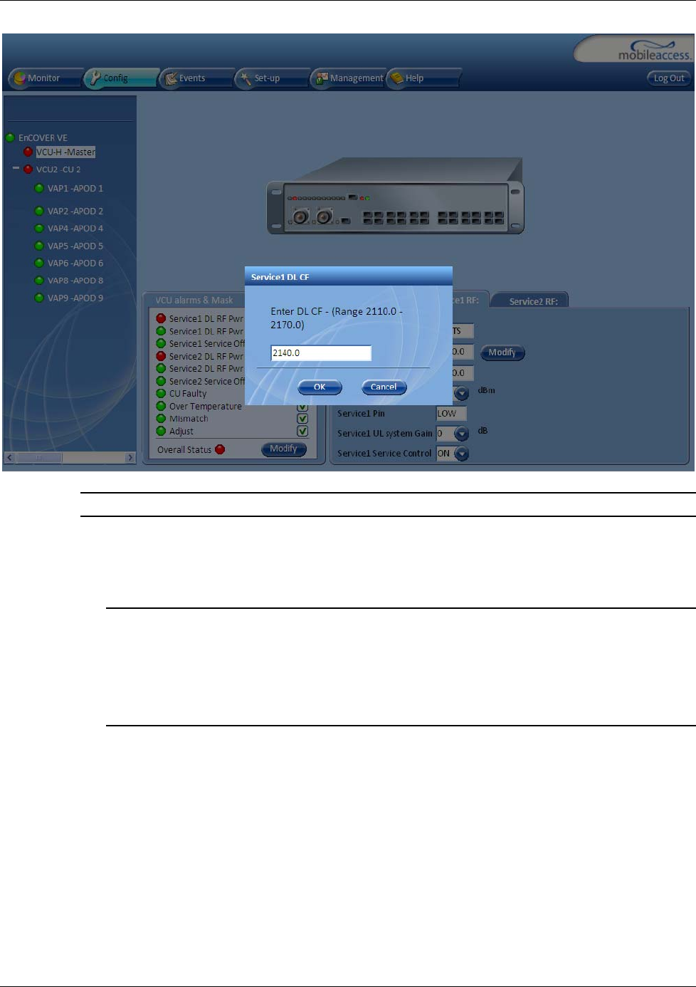
10. Set the RF parameters for each connected service (up to two). Each service
(Service1/Service2) is configured through its’ corresponding tab. To configure the service RF
parameters:
• Select the Service tab (Service1/Service2) of the service to be configured.
• Click Modify and enter the DL central frequency (first carrier) for each service according to
the following ranges:
• EGSM: 925 – 960 MHz
• UMTS: 2110 – 2170 MHz
• PCS: 1930 – 1990 MHz
• CELL: 869 89 MHz
• DCS: 1805 – 1880 MHz
VCU Unit Installation and Configuration
Dual Band EnCOVER VE™ Instant Coverage Solution User Manual 30
Note: The Service DL CF dialog displays the relevant range for each service.
• Click OK.
• Define Max expected power of BTS (0-33dBm)
• Define UL attenuation level for each service (0-25dB)
Notes:
1. Max expected Pin and Service CF parameters are service dependent and can be obtained
from your service provider.
2. The remaining parameters are predefined to their default values. (Service Bandwidth is
set to 15MHz for EGSM, UMTS and CELL and to 20Mhz for DCS and PCS).
3. Any updates of the service Central Frequency definition is sent to all connected VAPs.
VCU Unit Installation and Configuration
Dual Band EnCOVER VE™ Instant Coverage Solution User Manual 31
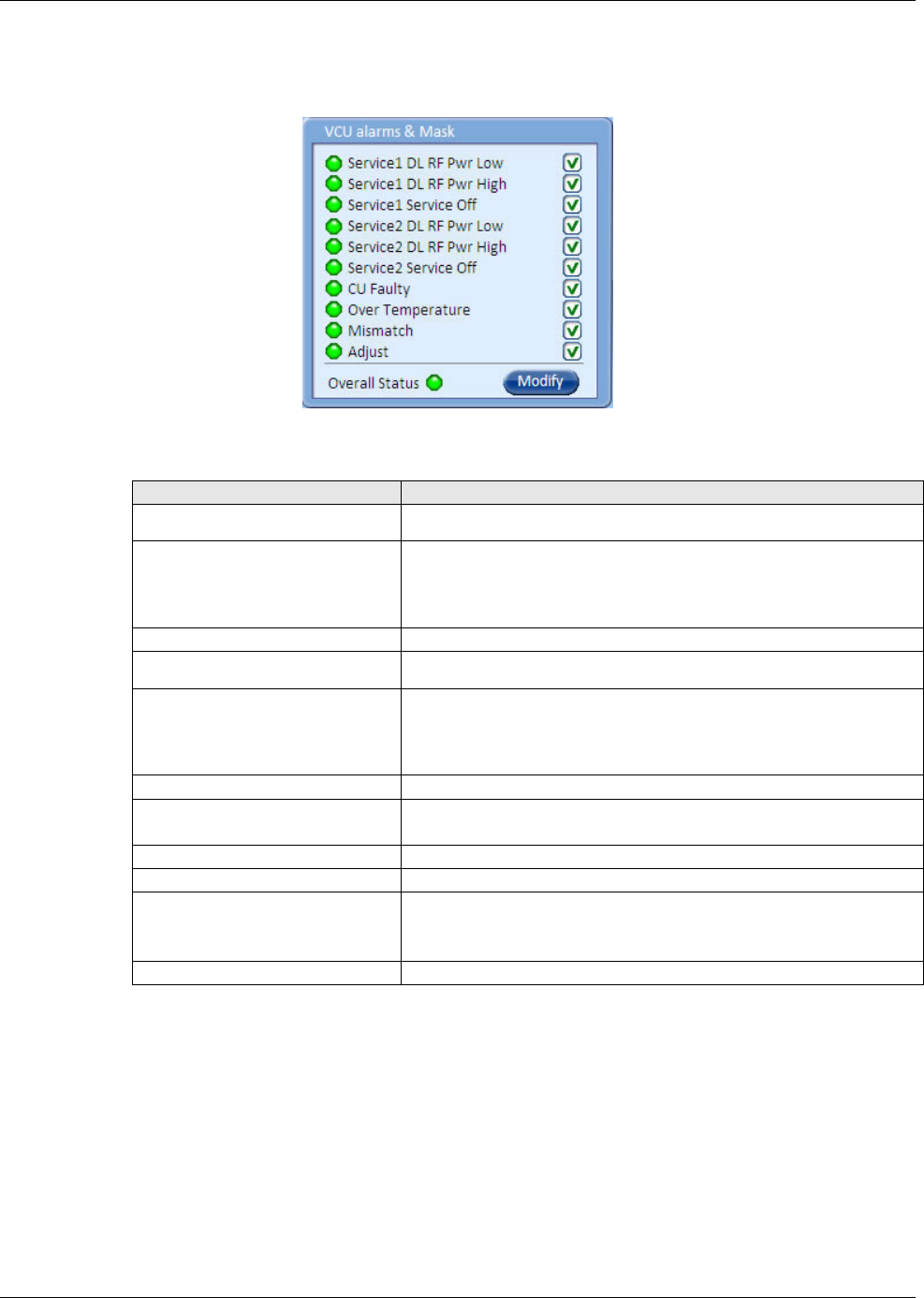
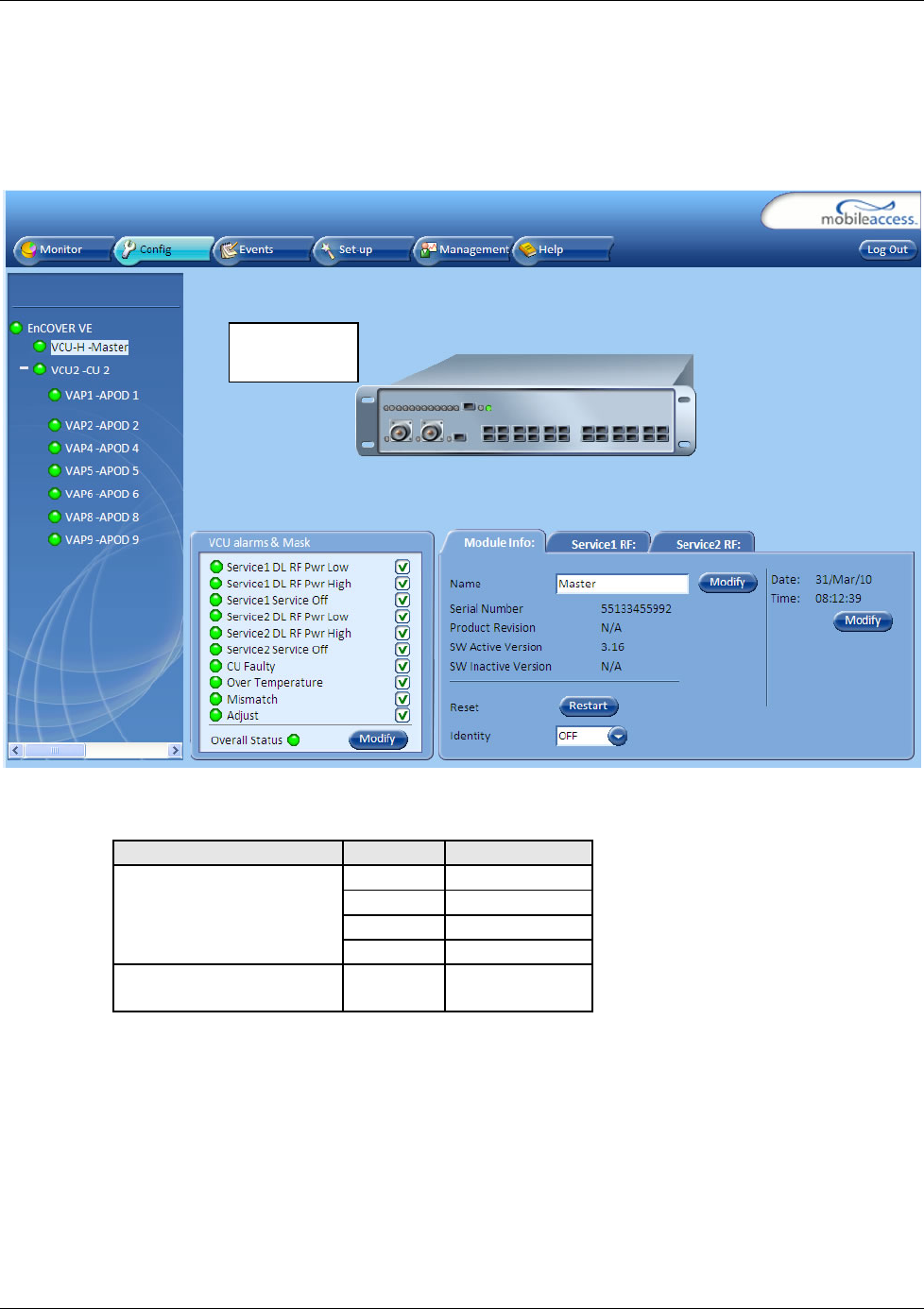
11. To verify proper operation of the system, refer to the Alarms sub-tab (in the Config tab).
See following figure.
12. Verify that all the alarms are GREEN. Refer to the alarm descriptions in the table following
the figure below.
Alarm Description
Service 1 DL RF Pwr Low RED - DL RF Power is lower than 5dBm.
Service 1 DL RF Pwr High RED - the input power exceeds the maximum limit and
cannot be attenuated to the required limit. Traffic is
disconnected.
Service 1 Service Off User has disabled service
Service 2 DL RF Pwr Low RED - DL RF Power is lower than 5dBm.
Service 2 DL RF Pwr High RED - the input power exceeds the maximum limit and
cannot be attenuated to the required limit. Traffic is
disconnected.
Service 2 Service Off User has disabled service
CU Faulty RED - VCU fault. Remove and re-apply power to VCU or
push the Reset button. If problem persists, replace VCU.
Over Temperature Temperature of unit exceeds normal range.
Mismatch Red – Mismatch of services
Adjust Only relevant to control unit defined as a slave unit:
RED – Indicates dB loss over the coax cable (either coax is
shorter than 10m or longer than 100m or faulty)
Overall Status Indicates Fault (RED) level or GREEN if there are no faults.
VCU Unit Installation and Configuration
Dual Band EnCOVER VE™ Instant Coverage Solution User Manual 32
Note: To briefly check the VCU status, click on the VCU name in the Topology Tree. The VCU
icon will appear, showing the LEDs status.
4.4.3 Provisioning the Slave VCUs
Note: The Slave VCUs management and configuration is performed through a remote connection
to the Master VCU, via the web management. Before provisioning the Slave VCUs verify that the
Master VCU unit, to which it is connected, has been provisioned (see section
4.4.1).
The Slave VCU RF parameters are set via the Master VCU, therefore there is no need to
configure the RF parameters individually for each connected Slave VCU. It is recommended to
assign each Slave VCU an indicative name.
Master VCU icon
VCU Unit Installation and Configuration
Dual Band EnCOVER VE™ Instant Coverage Solution User Manual 33
To assign a name to a Slave VCU:
1. Connect to the Master VCU unit (either locally as explained in section 4.4.1 or remotely) and
select the Slave VCU to be provisioned from the Network Topology Tree.
Each VCU has a default name of the form “VCUPx-name”, where:
• Px - Master VCU port number to which the Slave VCU is connected
• Name - user-defined name
2. To assign the Slave VCU an indicative name:
• Select the Module Info Tab
• Click the Modify button
• Type the unit name (up to 20 alpha-numeric characters) and click OK.
4.5 What Next?
Do not disconnect the Web Management application from the Master VCU; you will be using it to
verify the connections after all the VAPs are placed in their locations.
Click Modify
Selected Slave
VCU-
EnCOVER VE™ Access Pod (VAP) Installation and Commissioning
Dual Band EnCOVER VE™ Instant Coverage Solution User Manual 34
5 EnCOVER VE™ Access Pod (VAP)
Installation and Commissioning
This section provides a description of the EnCOVER VE™ Access Pods (VAPs) installation,
verification and monitoring procedures.
5.1 VAP Installation
The VAPs installation procedure consists of connecting each VAP to the Ethernet jack in the
appropriate location to provide optimal coverage (see sections 3.4 and 5.1.2).
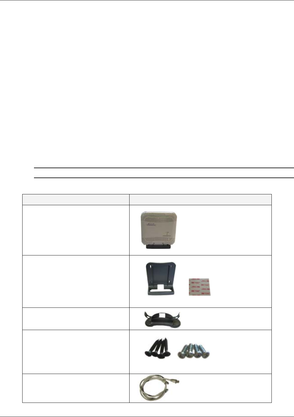
5.1.1 VAP Kit Contents
The EnCOVER VE™ Dual Band Solution VAP kit includes:
Note: VAPs are provided with two mounting options: desk-mount and wall-mount
Table 10: VAP Kit
Kit Items UNIT
EnCOVER VE™ Access Pod (VAPs)
Wall-mount adaptor (with double
sided sticky tape for fast installation)
Desk-mount adaptor
8 screws:
o 4 short screws – for securing
adaptor to pod
o 4 longer screws – for securing
wall-mount adaptor to the wall
(“anti-theft” installation)
RJ-45 jumper cable
Wall-mount adaptor
Double sided tape
Long screws Short screws

EnCOVER VE™ Access Pod (VAP) Installation and Commissioning
Dual Band EnCOVER VE™ Instant Coverage Solution User Manual 35
5.1.2 VAP Locations and Mounting
It is recommended to place the VAPs on top of desks, cube walls, filing cabinets or higher on
walls so as to maximize the provided coverage per VAP.
Note: Mounting a VAP beneath a desk or other low location (i.e office corner) decreases the
effective coverage of the VAP and therefore a higher number of VAPs would be required to cover
the same area.
When installing the VAPs, consider the following:
• Placing the units, as much as possible, in an open area
• Availability of CAT-5e/6 infrastructure
• The VAPs plug into standard (RJ-45) Ethernet connection jacks.
• If the jack to be used is already connected to Ethernet switch. For more information see
3.4.2 and 4.3.1.
• Aesthetics of the VAP location
5.1.2.1 Desk mount
• Secure the Desk-mount adaptor to the EnCOVER VE™ Access Pod using the supplied screws
• Connect the RJ-45 jumper cable (CAT-5e/6) to the VAP
• Place the VAP on a flat surface according to the planed location
• Plug the other side of the cable into adjacent standard (RJ-45) Ethernet connection jack.
(the adaptor screws and cable are included in the VAP kit)
• When using an external antenna, connect the Ext. Antenna SMA connector(s) to the external
antenna(s). This option must be SW configured via the web GUI (internal antenna is enabled
by default).
Note: The maximum external antenna gain should not exceed 10 dBi.
• Verify that the VAP receives power and sync up to the VCU via the LEDs on the unit.
+ =
*External Antenna connectors only available on specific VAP models (VAP-CELL-PCSE-EXTAN, VAP-DCS-UMTSE, VAP-DCS-UMTSE-EXTAN,
VAP-EGSM-UMTSE-EXTAN) (see 1.3.1).
Desk-mount ada
p
tor
Access Pod
Ext. Antenna SM
A
connector* RJ-45 to
computer Ext. Antenna SMA
connector*
RJ-45 to
VCU
EnCOVER VE™ Access Pod (VAP) Installation and Commissioning
Dual Band EnCOVER VE™ Instant Coverage Solution User Manual 36
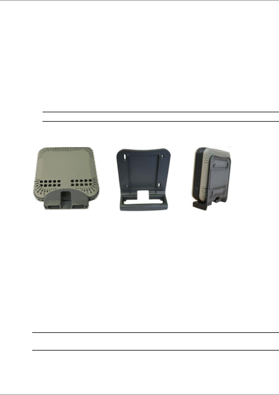
5.1.2.2 Wall Mount
Assemble the VAP to the wall-mount (the adaptor and wall mount screws, sticky tape and cable
are included in the VAP kit as described in Table 10: VAP Kit)
• Connect the RJ-45 jumper cable (CAT-5e/6) to the VAP
• Attach the VAP to the wall according to the planed location using supplied screws (for “anti-
theft” installation) or the double sided sticky tape for the wall-mount adaptor (for “plug-and-
play” installation)
• Plug the other side of the cable into the adjacent standard (RJ-45) Ethernet connection jack.
• When using an external antenna, connect the Ext. Antenna SMA connector(s) to the external
antenna(s). This option must be SW configured via the web GUI (internal antenna is enabled
by default).
Note: The maximum external antenna gain should not exceed 10 dBi.
• Verify that the VAP receives power and sync up to the VCU via the LEDs on the unit.
+ =
5.2 Verifying Coverage
Verify coverage in the areas, adding and moving VAPs for optimal coverage according to the
principles described in 3.3.
5.3 Naming the VAPs, Verifying Connections and
Monitoring
The VAPs are auto-discovered by the VCU and can be monitored via a remote or a local
connection to the system Master VCU. No configuration procedure is required; however, if you
wish, you may assign each VAP an identifiable name corresponding to its physical location.
Note: See section
6 for full explanation about navigating the EnCOVER VE™ Web GUI
application.
1. If a session is not already opened to the EnCOVER VE™ Web management application, open
a session to the Master VCU according to section 4.4.1.
2. Select a VAP from the Network Topology Tree.
Access Pod Wallmount Adaptor Assembly
EnCOVER VE™ Access Pod (VAP) Installation and Commissioning
Dual Band EnCOVER VE™ Instant Coverage Solution User Manual 37
Each VAP has a default name of the form VAP Px-name where:
• Px – Number of Slave VCU port to which the VAP is connected
• name - User-defined name
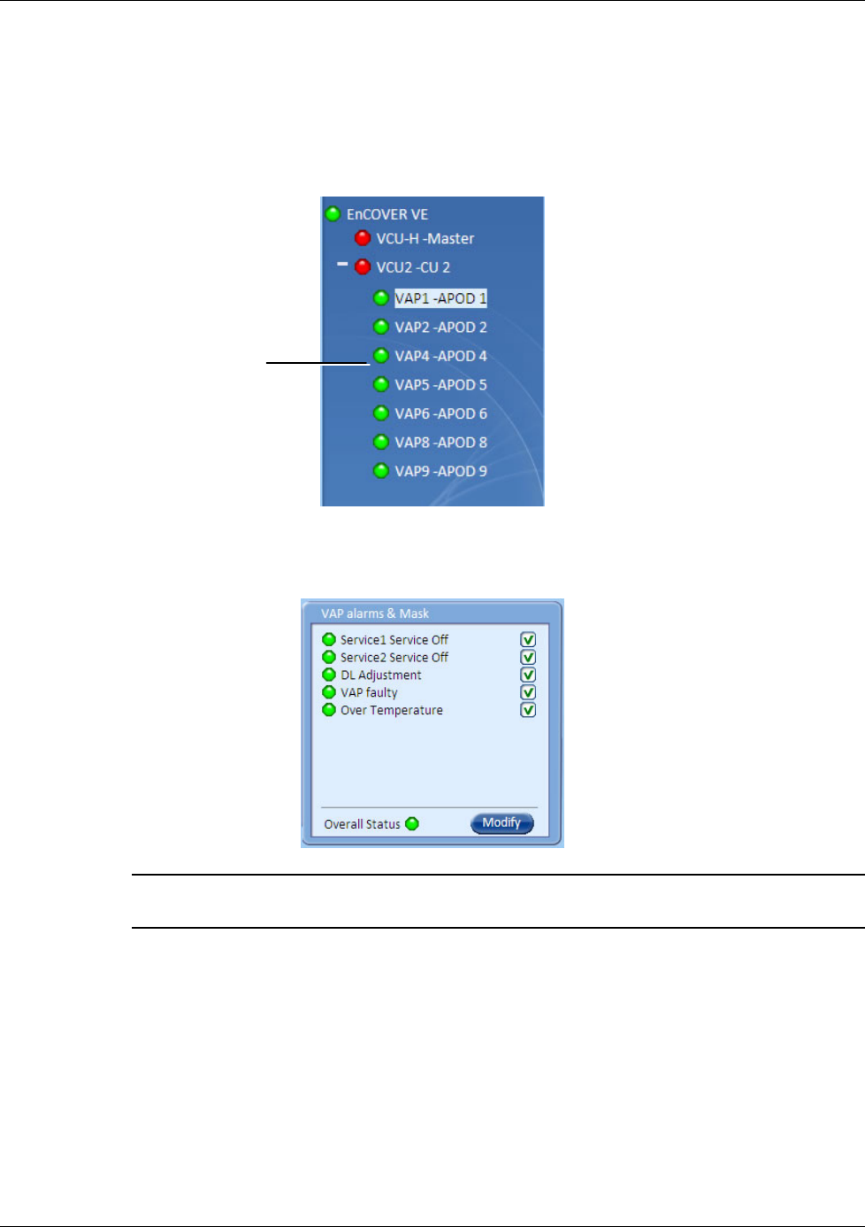
3. In the Network Topology Tree, under the Control Unit, verify that a GREEN (or RED) circle is
displayed for each connected VAP.
• If a VAP is
not
green, select the VAP from the network topology tree then select the
Config tab. Refer to the Alarms tab work area. The alarms for the selected VAP are
displayed.
Note: For more information, on the VAP Alarms, see section Error! Reference source not
found..
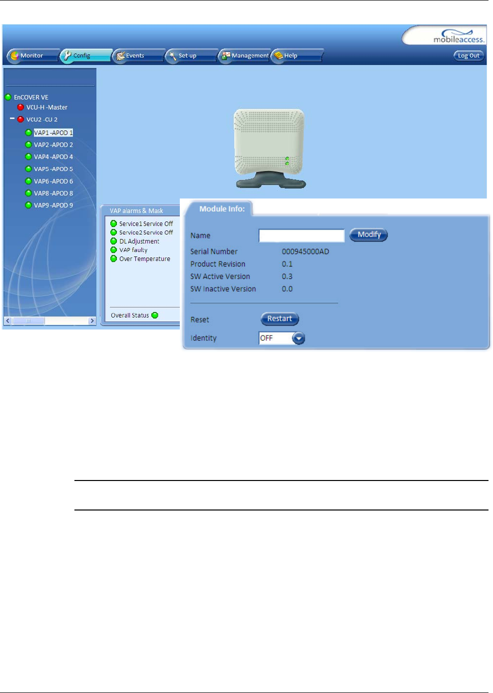
4. Refer to the Config Module info tab.
Connected VAP
EnCOVER VE™ Access Pod (VAP) Installation and Commissioning
Dual Band EnCOVER VE™ Instant Coverage Solution User Manual 38
5. Assign each VAP a name as follows:
• Click the Modify button.
• Click OK.
6. When required to transmit the RF signal through a connected external antenna (if VAP
model supports this option):
• Refer to the Service 1 and/or Service 2 tabs
• Enable the External Antenna option
Note: If the external antenna option is not enabled, the signal is transmitted via the
integrated internal antenna, by default.
7. Verify the system connections according to the following section ( 6 ).
Navigating the Management Application
Dual Band EnCOVER VE™ Instant Coverage Solution User Manual 39
6 Navigating the Management Application
This section describes the EnCOVER VE™ Web GUI management application and each of the
tabs.
The EnCOVER VE™ Web management application is accessed through any standard web
browser connected to the Master VCU via a network within the same subnet as the Master VCU
or a different subnet which is routable.
6.1 Opening a Session and Authentication Levels
After the initial configuration (as explained in 4.4.1) the EnCOVER VE™ system can be accessed
via the network.
To access the system:
1. Open a web browser and type in the address bar the Master VCU’s IP address as you set it
in the Master VCU configuration operation (see section 4.4.1).
2. The Login pane appears. Select your User Name and type in your password. The following
authentication levels are available:
• Operator: password = oper. This user has Read Only access.
• Field Engineer: password = eng. This user has access to basic configuration options.
• Technical Support: for MobileAccess service personnel.
Field Enginee
r
Navigating the Management Application
Dual Band EnCOVER VE™ Instant Coverage Solution User Manual 40
6.2 Main Window
The Web GUI Main window appears after login.
The Main window consists of two main areas:
• Menu Bar – Provides the following tabs:
• Monitor – Provides a summarized view of the system status
• Config(uration) – Provides the selected units’ configuration parameters and alarms
• Events – Provides the events list and trap mask
• Set up – Provides wizards that enable defining groups of APods
• Management – Provides upgrade, IP configuration and security options
• Help
• Sub-tabs – Provide options (tabs) that correspond to the selected menu bar tab
Menu ba
r
Sub-tabs
corresponding
to menu ba
r
options
Navigating the Management Application
Dual Band EnCOVER VE™ Instant Coverage Solution User Manual 41
6.3 Configuration Tab
The Configuration tab provides the general information and service RF parameters for
configuration of the units appearing in the Network Topology tree. The Configuration window is
accessed by clicking on the Config tab in the main menu bar. The information and parameters
displayed in the Configuration sub-tabs vary depending on whether a VCU or VAP is selected in
the topology tree.
6.3.1 VCU Configuration
To access a VCU Configuration tab
Select a Master VCU/Slave VCU from the network topology tree on the left hand side of the
window a click the Configuration tab from the menu-bar.
Selected VCU VCU Icon display
Configuration tab
Navigating the Management Application
Dual Band EnCOVER VE™ Instant Coverage Solution User Manual 42
The Configuration tab is divided in to three main areas:
• Network Topology Tree – Displays the system units (Master VCU, Slave VCUs and VAPs) and
their status
• Display area – Displays the icon of the selected unit including the LED statuses
• Work area – Displays the Module Info, alarms and RF tabs corresponding to the unit selected
in the topology tree (Master VCU, Slave VCU or VAP)
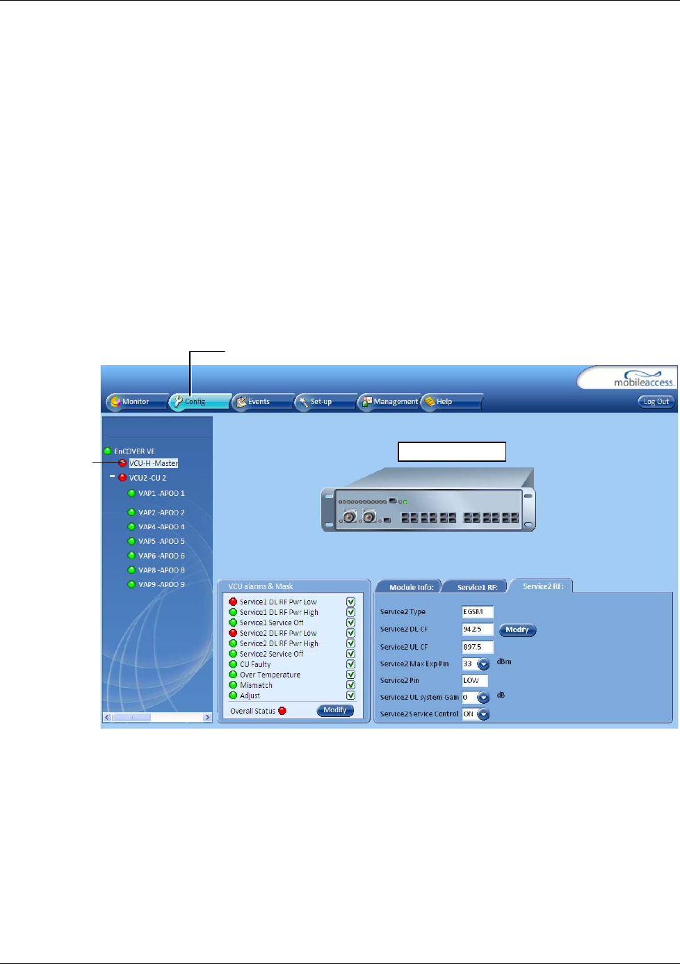
6.3.2 Network Topology Tree
The Configuration Network Topology Tree appears on the left hand side when the Config tab is
selected and displays the Master VCU, Slave VCUs and VAPs in two levels:
• First level – VCU
• Second level – Up to 12 VAPs
Note: The root is EnCOVER VE.
Each unit is assigned a Type Px-name:
• Type – VCU-H, VCU or VAP (for Master VCU, Slave VCU or VE™ Access Pod)
• Px - VCU port number (not relevant for Master VCU)
• Name – user defined
Each unit is displayed with a colored bullet that indicates its’ status:
Color Indicates
Green OK
Yellow Minor alarm
Red Major alarm
Gray No communication
Root
Master VCU
–
first level
VAP
–
second level
Navigating the Management Application
Dual Band EnCOVER VE™ Instant Coverage Solution User Manual 43
6.3.3 Configuration Display Area
When selecting an element (Master VCU/Slave VCU or VAP) in the network topology tree an icon
representing the unit is displayed in the Configuration tab display area
The following table provides a description of the LEDs displayed for the VCU and VAP icons and
that reflect the actual unit LEDs.
Unit LED No.
Master VCU/Slave VCU RF 2
IF 1
Port Pwr 12
Port Act 12
VAP Status
LEDs 2
Icon display
area
Navigating the Management Application
Dual Band EnCOVER VE™ Instant Coverage Solution User Manual 44
6.3.4 Alarms Tab
The alarms displayed in the Alarms tab corresponds to the system element selected in the
topology tree and vary depending on whether a VCU or VAP is selected.
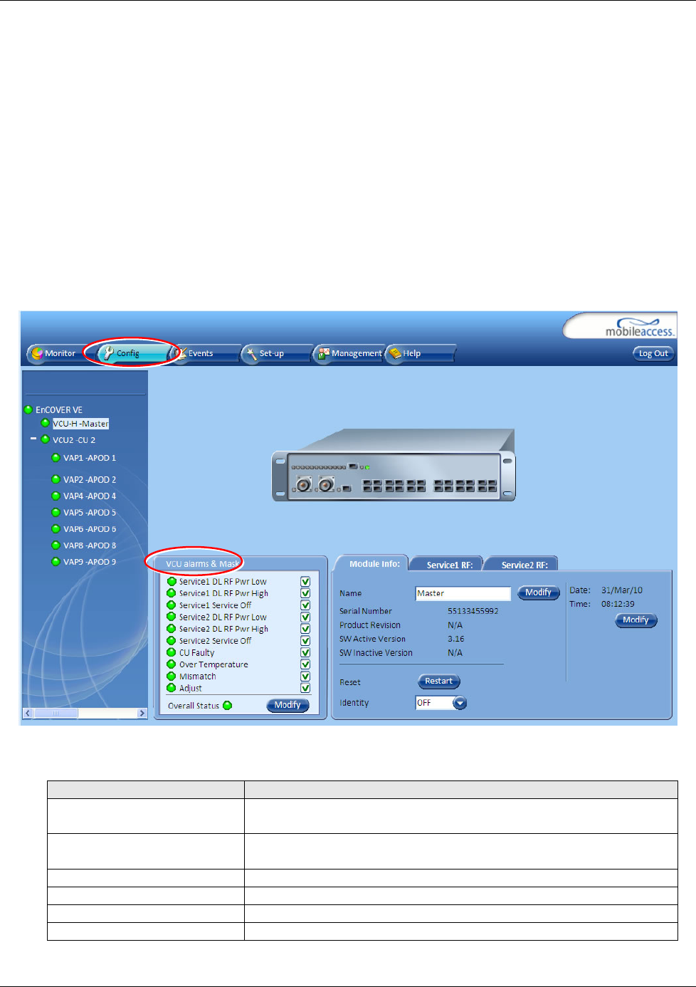
6.3.4.1 VCU Alarms Tab
When a VCU element is selected in the topology tree, the Alarm tab displays the main alarms in
the unit.
To access Alarms Tab of VCU
In the Topology Tree, click the Control Unit (VCU), click the Config(uration) tab in the menu
bar located at the top of the window and click the VCU Alarms sub tab.
If one or more alarms occur, the corresponding Status indicator is illuminated in RED. If the VCU
is OK and no fault occurs, the Overall Status indicator will show GREEN.
Alarm Description
Service 1/2 DL RF Pwr Low
Input power of specific service lower than 5dBm
Service 1/2 DL RF Pwr High Input power of specific service is higher than maximum expected
power defined in the RF tab
Service 1/2 User has disabled service
Overall temperature Temperature of unit exceeds normal range
CU faulty Hardware fault detected in VCU
Overall status Indicates Fault (RED) level or GREEN if there are no faults
Navigating the Management Application
Dual Band EnCOVER VE™ Instant Coverage Solution User Manual 45
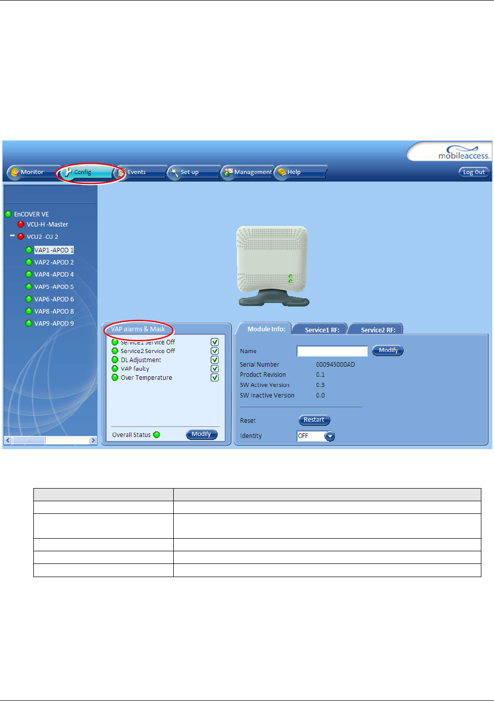
6.3.4.2 VAP Alarms Tab
When a VAP element is selected in the topology tree, the Alarm tab displays the main alarms in
the unit.
To access Alarms Tab of VAP
In the Topology Tree, click the VAP, click the Config(uration) tab in the menu bar located at
the top of the window and click the VAP Alarms sub tab.
If one or more alarms occur, the corresponding Status indicator is illuminated in RED. If the VAP
is OK and no fault occurs, the Overall Status indicator will show GREEN.
Alarm Description
Service 1/2 Off User has disabled service
DL Adjustment Indicates dB loss over the coax cable (either coax is shorter than
10m or longer than 100m or faulty)
VAP Faulty A fault has been detected in the VAP
Overall temperature Temperature of unit exceeds normal range
Overall status Indicates Fault (RED) level or GREEN if there are no faults
Navigating the Management Application
Dual Band EnCOVER VE™ Instant Coverage Solution User Manual 46
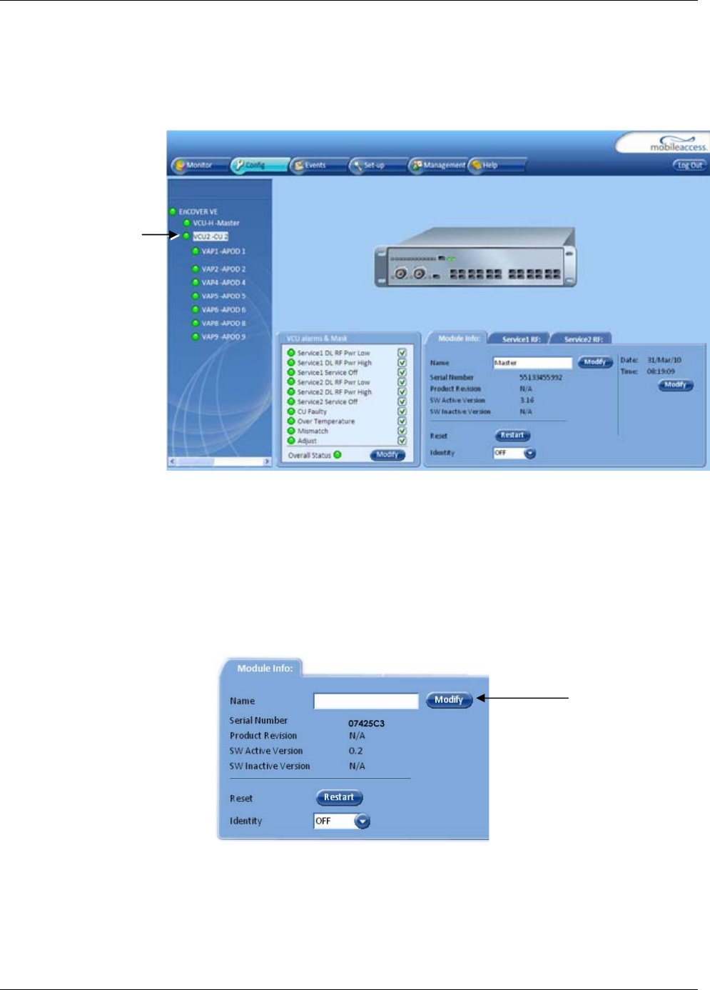
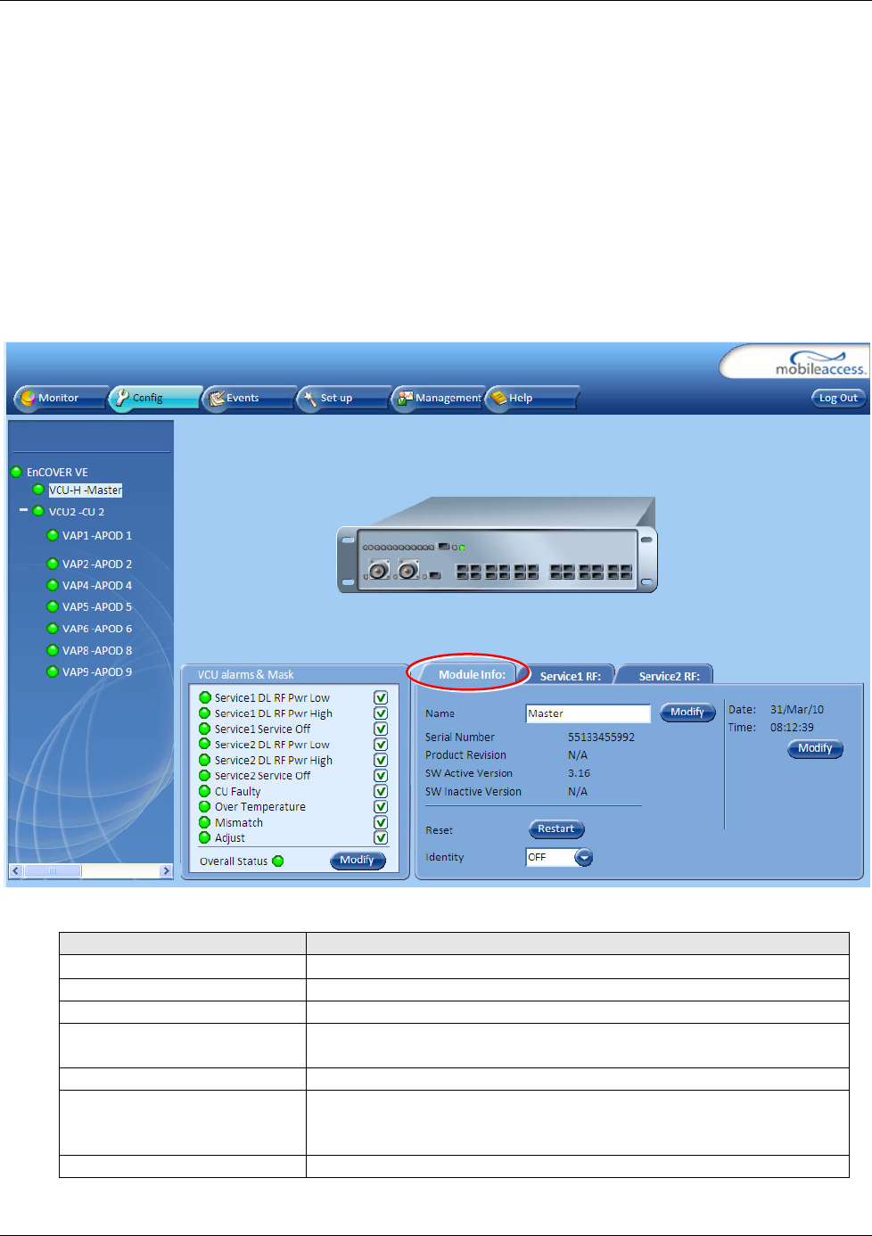
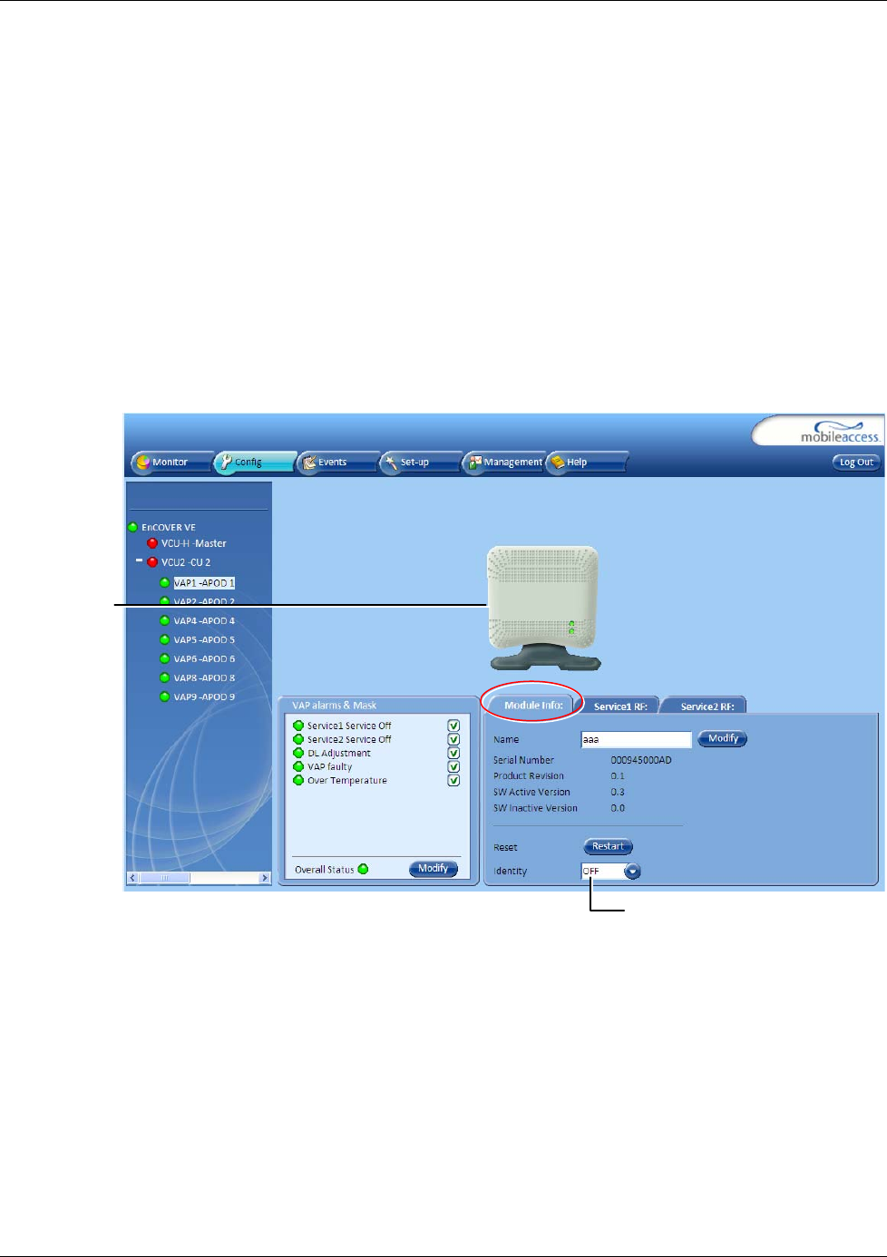
6.3.5 Module Info
The Module Info tab displays the selected elements’ (VCU or VAP) general information (such
as, unit name and SW versions. The displayed information corresponds to the selected element
(VCU or VAP).
To access the Module Info tab
Select the system element from the network topology tree and click on the Module Info sub-
tab.
The following information is displayed:
Field Description
Name User defined name for system element (up to 20 characters)
Serial Number Factory set ID number
Product Revision Revision number of VCU/VAP
SW Active Version Version of the SW currently being used to manage and monitor
the system
SW Inactive Version Version of other system SW version not in use
Identify button Enabling this option enables finding the physical location of the
selected element (see 7.1). When this option is set to ON, the
LEDs on the corresponding Access POD/VCU flickers.
Restart button SW reset of the unit
Navigating the Management Application
Dual Band EnCOVER VE™ Instant Coverage Solution User Manual 47
6.3.6 Service Tabs (RF Parameters)
The Service 1 and Service 2 tabs provide the configurable RF parameters corresponding to the
element selected in the network topology tree (VCU/VAP). Up to two service RF tabs are
displayed – one for each
active
service. The displayed RF parameters are similar for both service
tabs.
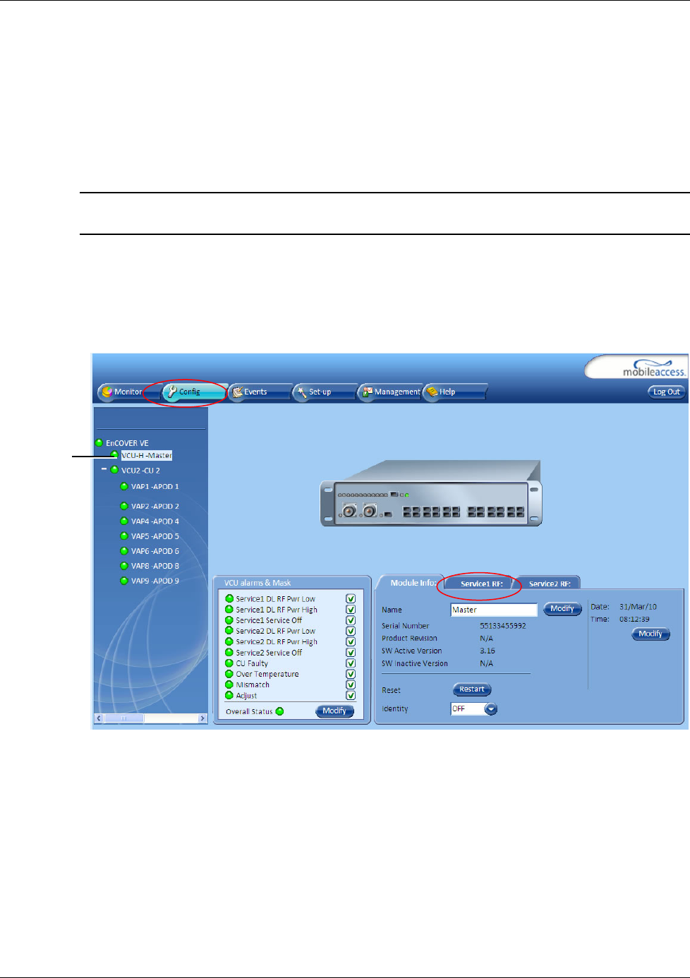
6.3.6.1 Master VCU/Slave VCU Service RF Tab
Note: The RF parameters are not displayed for control units functioning as slaves to Master VCU
units.
To access the Service RF tab
Click the Config tab from the main menu bar and then select the control unit from the network
topology and click the
Service RF
tab. The parameters displayed in Service RF tabs correspond to
the selected element.
Selected
Master VCU
Navigating the Management Application
Dual Band EnCOVER VE™ Instant Coverage Solution User Manual 48
The following table provides a description of the RF parameters displayed in the Service RF tabs.
Parameter Description
Type Set (read only) according to unit type (e.g. EGSM / UMTS)
DL CF* DL Center frequency (from BTS). User defined, according to connected
service (EGSM / UMTS / CELL / PCS / DCS).
UL CF UL center frequency (from BTS) – corresponding to defined DL Center
Frequency. Automatically assigned by the system according to the DL
frequency.
Max Exp Pin* Maximum expected input power from the BTS. Used for adjustment
procedure. Range: 0-33 dBm. User defined.
Pin Actual measured Pin (read only)
UL System Gain Used for adjusting the UL system gain. Range: -15 dB to +15 dB
Service Control Enables (On)/Disables (Off) the service
* Required parameters to be provisioned by the user.
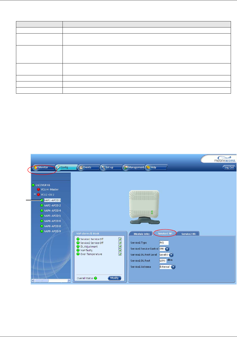
6.3.6.2 VAP Service RF Tab
To access the Service RF tab
Click the Config tab from the main menu bar and then select the VAP from the network
topology and click the
Service RF
tab. The parameters displayed in Service RF tabs correspond to
the selected element.
Selected
VAP
Navigating the Management Application
Dual Band EnCOVER VE™ Instant Coverage Solution User Manual 49
The following table provides a description of the RF parameters displayed in the Service RF tabs.
Parameter Description
Type Set according to unit type (e.g. EGSM /UMTS)
Service Control Used to Disable (Off) or Enable (On) the service for the specific VAP
DL Pout Level Low – measured power is below required level
Level 0 - measured power is at required level
Level 1 – measured power is (approx.) 5 dB less than the required level
Level 2 - measured power is (approx.) 10 dB less than the required level
High - measured power is over the maximum required level
UL Pout Level Corresponds to defined DL Pout level
Antenna Select External only if an external antenna is connected to this VAP.
Otherwise, the option should be set to Internal (default).
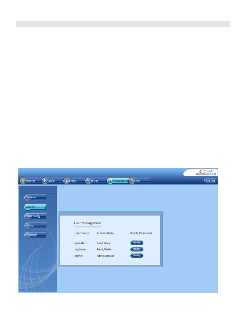
6.4 Management Tab
6.4.1 Security Tab – Changing Password
The Management - Security tab provides password change options. This tab is common to the
VCU and VAPs.
To set the application password or change an existing password
1. Select the Security option of the Management tab at the top of the window.
2. Click the Modify (Password) button of the User Name whose password is to be modified.
3. Enter the New Password and re-enter in the Confirm New Password field.
4. Click OK.
Troubleshooting
Dual Band EnCOVER VE™ Instant Coverage Solution User Manual 50
7 Troubleshooting
7.1 Finding a Specific VAP in the Building
It is recommended to assign each VAP an identifiable name corresponding to its physical location
as explained in section 5.3. If a name was not configured, or for some other reason a specific
VAP cannot be physically located, physically identify the VAP by following the instructions given
in the following example.
To locate a VAP
1. Click the Config tab from the main menu bar and select the VAP to be located from the
topology tree.
2. Click the Module Info sub-tab.
Selected VAP
Identify On/Off
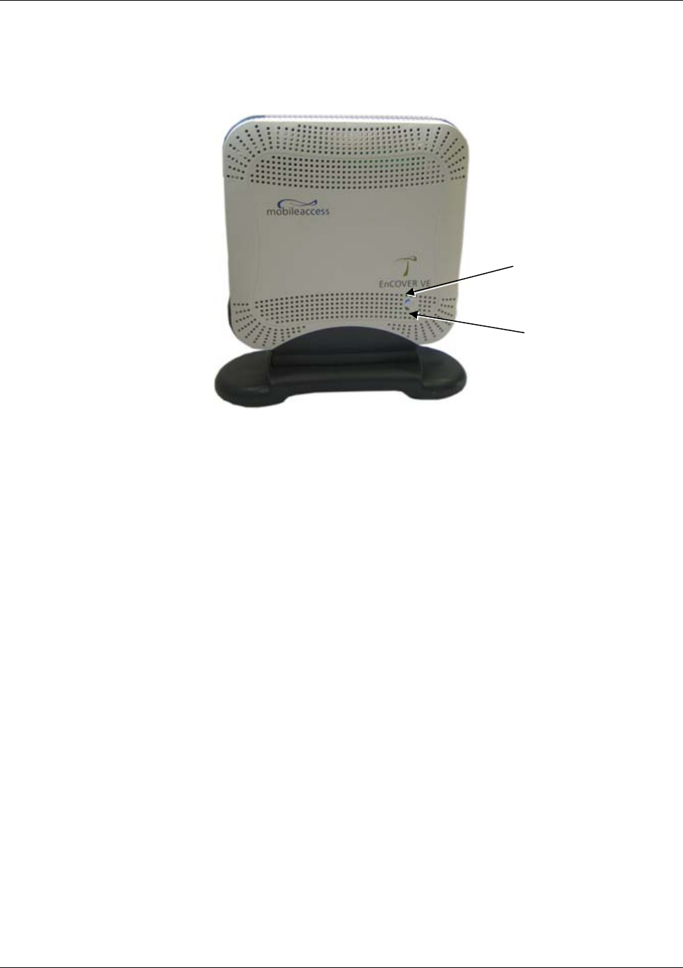
Troubleshooting
Dual Band EnCOVER VE™ Instant Coverage Solution User Manual 51
3. Set Identify to ON. The Activity LED (Blue) on the corresponding Access Pod will start
blinking fast. (You will need to physically locate the VAP to see the blinking LED).
4. Locate the Access Pod.
5. Once found – it is advisable to assign it an identifiable name via the Access Pod Module
Info tab as described in section 5.3 (e.g. floor 3, conf. room) and set the Identify field to
Off again.
Blue LED (Activity)
Green LED (PWR)

Dual Band EnCOVER VE™ Instant Coverage Solution User Manual 52
Appendix A - Traps
This section lists the Encover VE™ Dual - Band Controller and Access Pod traps
EnCOVER VE™ Control Unit Traps
No Trap Name Trap Description
1 HeartBeat System heart beat.
2 Service1LowRFcarrier (Major) Alert for low RF in VCU: 15 dB less than max expected power
3 Service1HighRFcarrier (Minor) Alert for High RF in VCU: 3 dB more than max expected power
4 Service1Off Major : user setting service to off
5 Service2LowRFcarrier (Major) Alert for low RF in VCU: 15 dB less than max expected power
6 Service2HighRFcarrier (Minor) Alert for High RF in VCU: 3 dB more than max expected power
7 Service2Off Major : user setting service to off
8 Control Unit Faulty Major: HW failure in CU
9 OverTemperature Minor: VCU temperature is too high.
10 AbnormalSetup Minor: Msmatched service types of more than two tiers
11 CU-SlaveDetected Notify: A slave control unit is detected by the Master VCU.
12 CU-SlaveDisconnected Notify: A slave control unit is disconnected from the Master VCU.
Encover VE™ APod Traps
No Trap Name Trap Description
1 AdjustmentSetup Major: Cable is either too lon
g
(more than 100m) or too short (less than
10m)
2 Service1Off (at APod) Minor: User set service too Off
3 Service2Off (at APod) Minor: User set service too Off
4 APod Faulty Major
5 OverTemperature Minor: APod temperature is too high.
6 APodDetected Notify: A VAP is detected by the VCU.
7 VAPDisconnected Notify: A VAP is disconnected from the VCU.