Corning Optical Communication VE-WIMAX-25E VE WiMAX 2.5 GHz DISTRIBUTED ANTENNA SYSTEM User Manual
Corning Optical Communication Wireless VE WiMAX 2.5 GHz DISTRIBUTED ANTENNA SYSTEM Users Manual
UserManual.wiki
>
Corning Optical Communication
>
VE WIMAX 25E User Manual
Users Manual
Navigation menu
Upload a User Manual
Namespaces
Wiki Guide
HTML
PDF
Info
Views
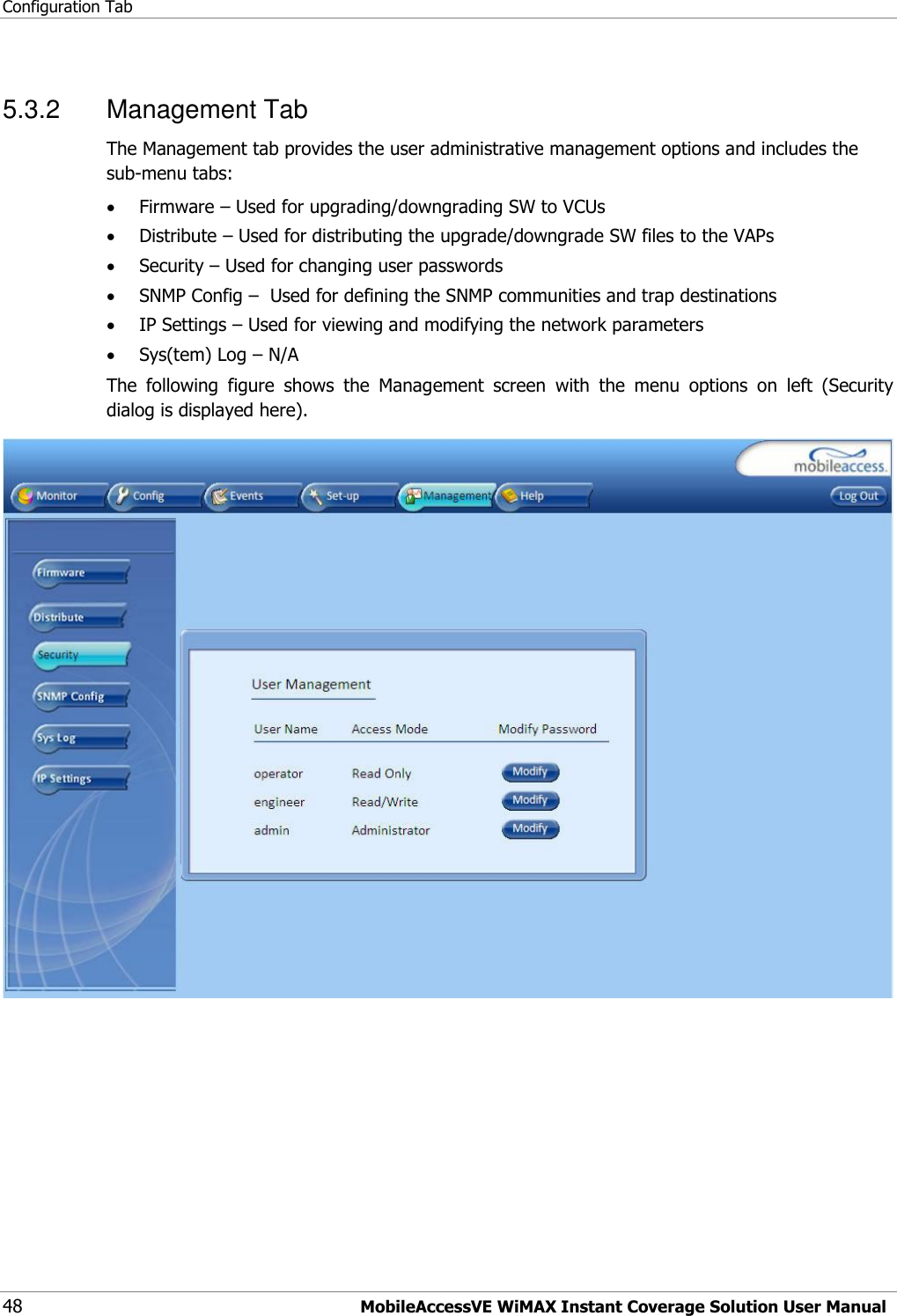
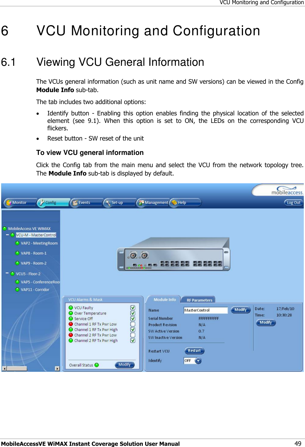
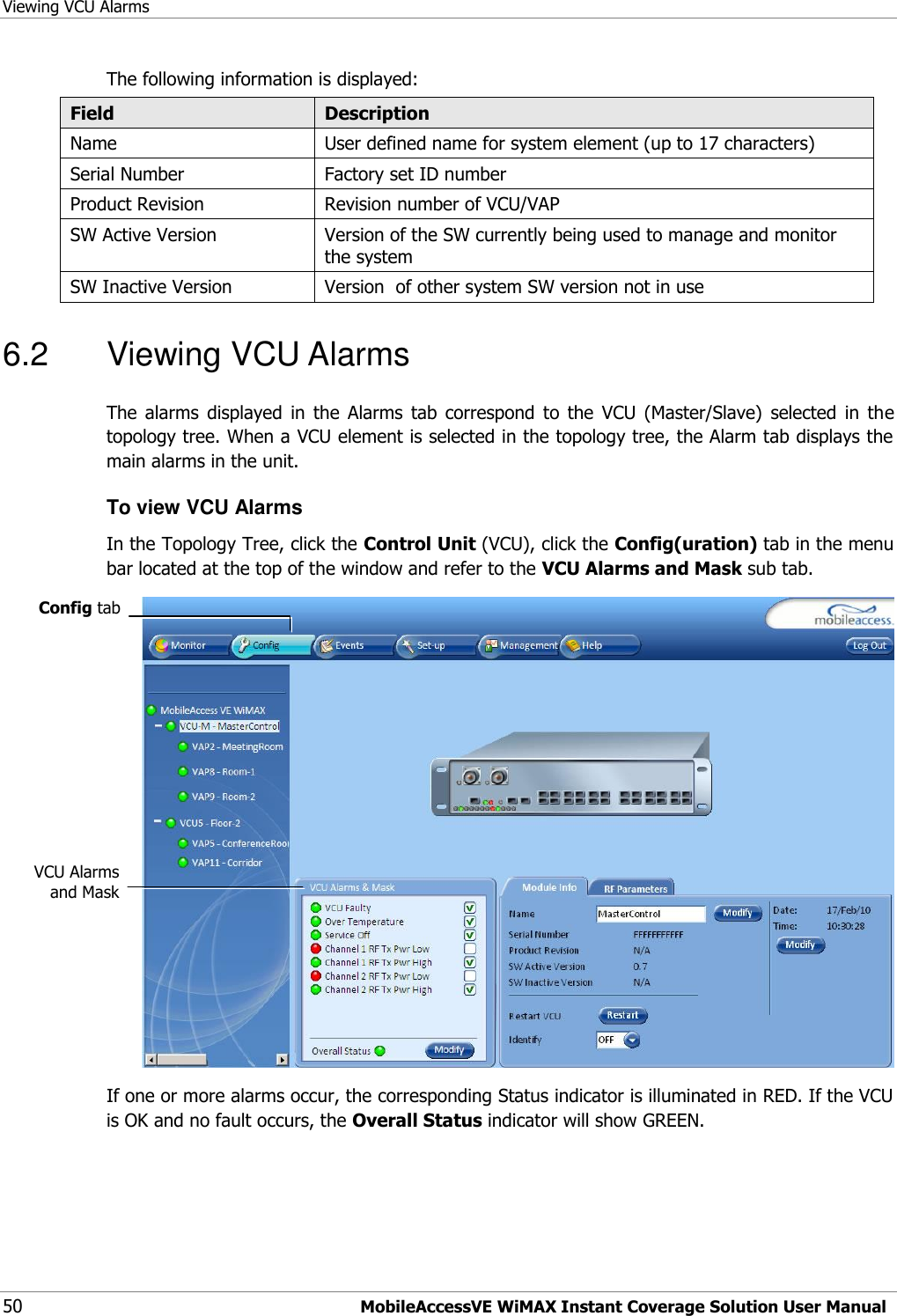
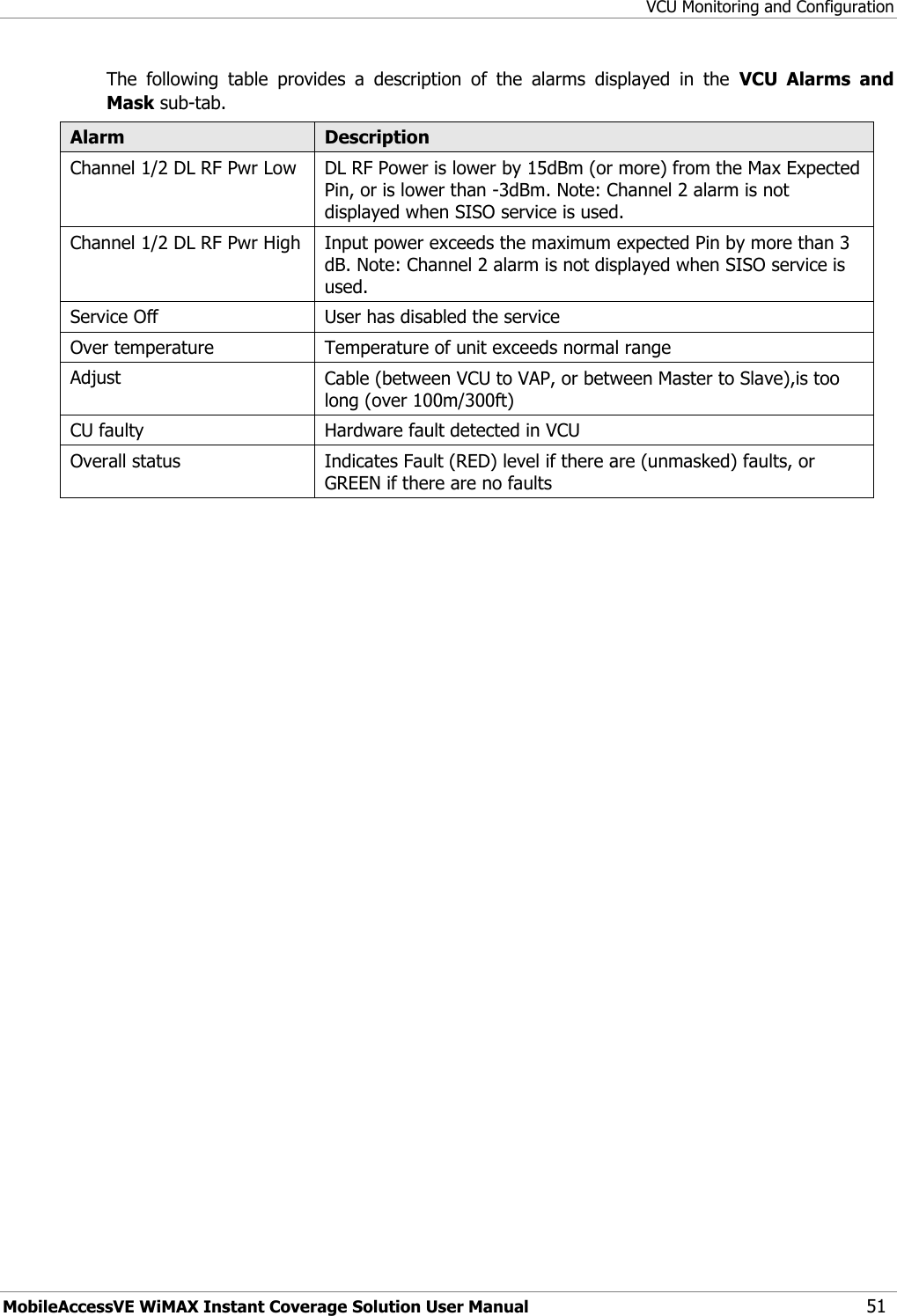
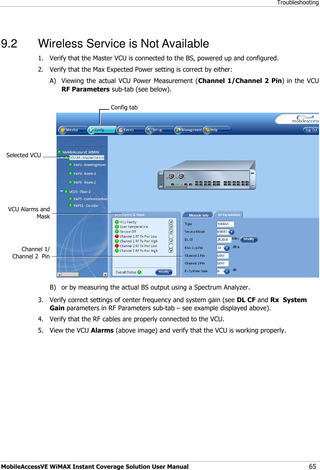
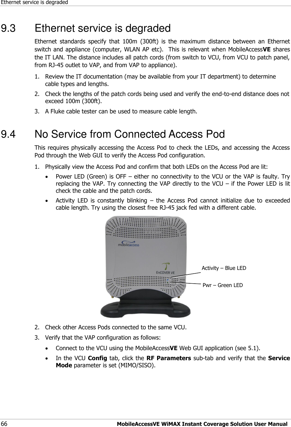
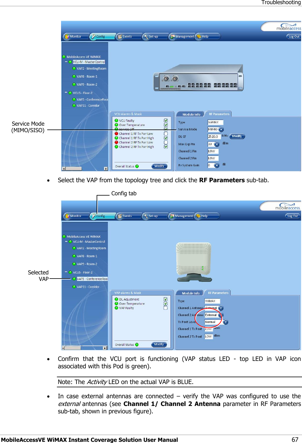
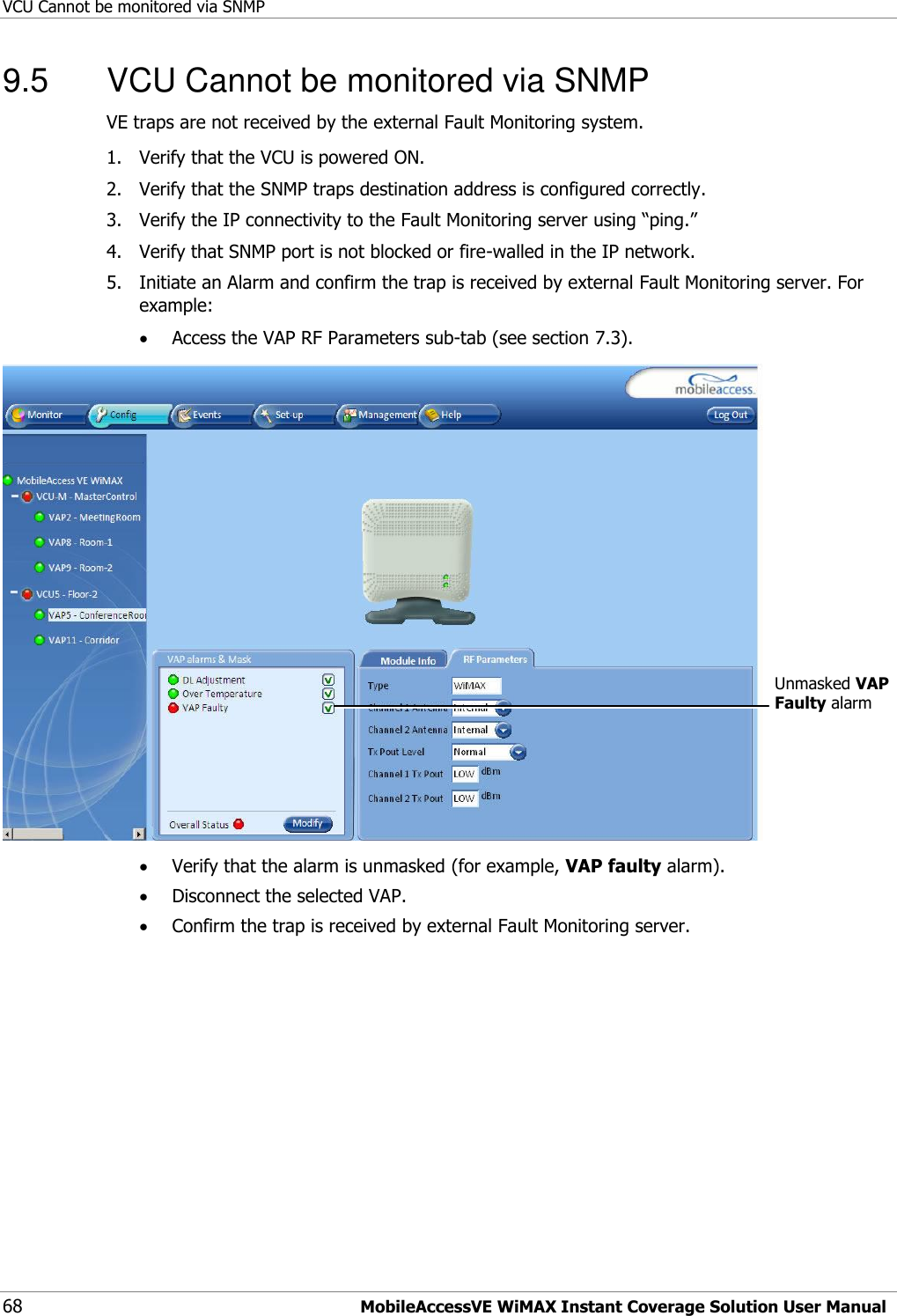
User Manual
Discussion / Help
Navigation