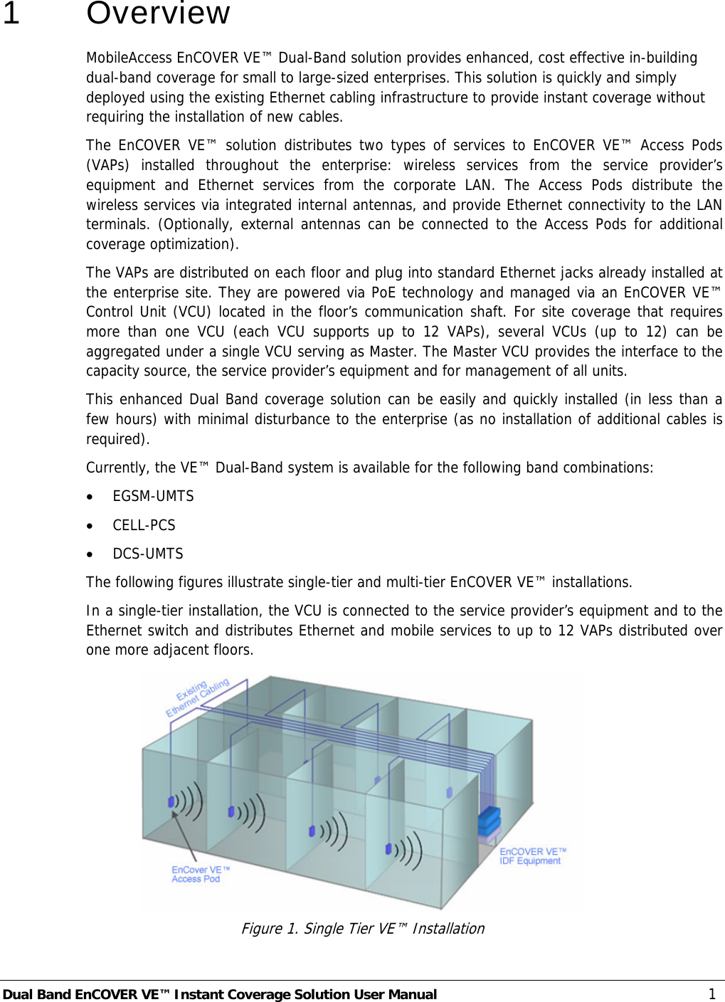
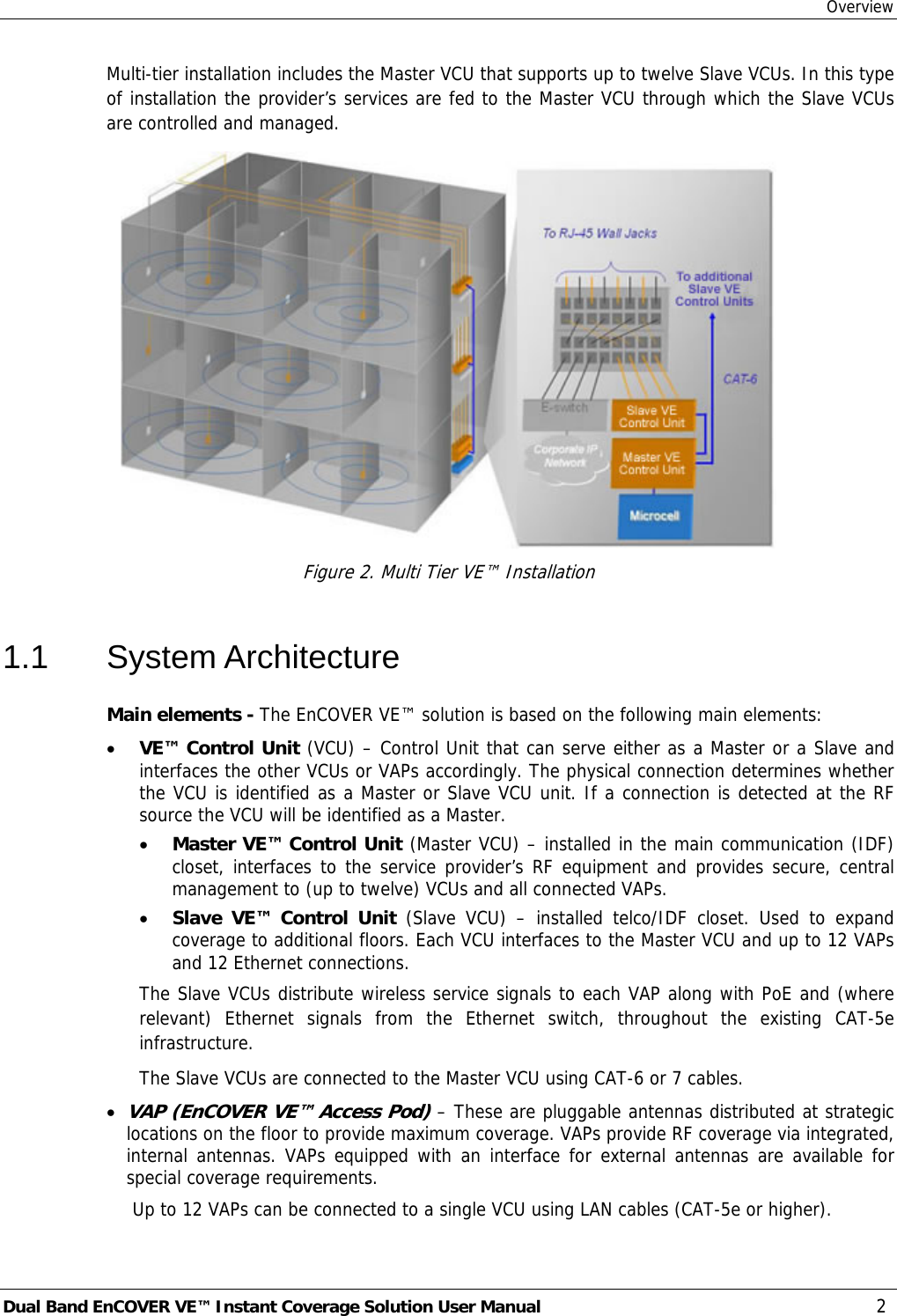
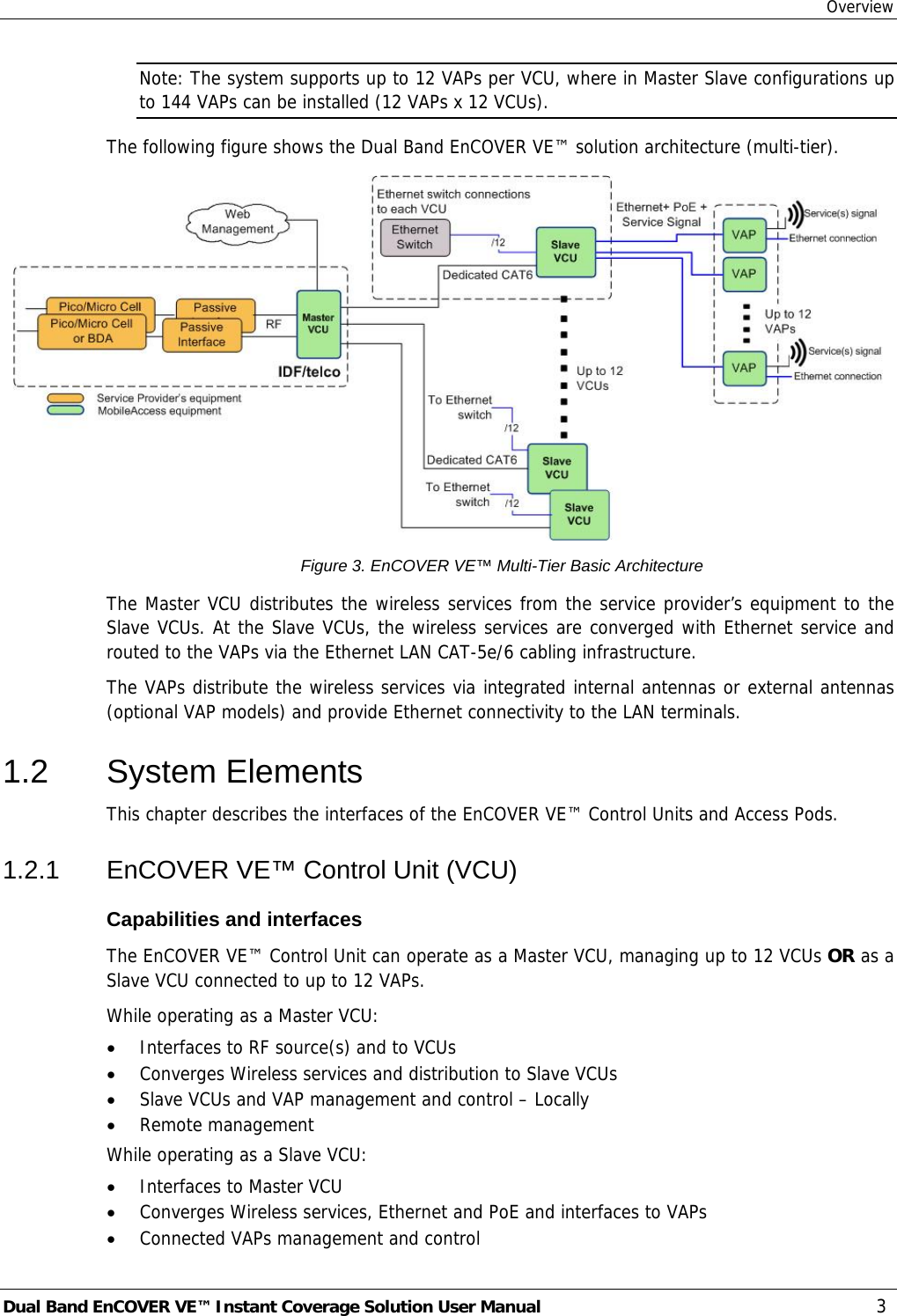
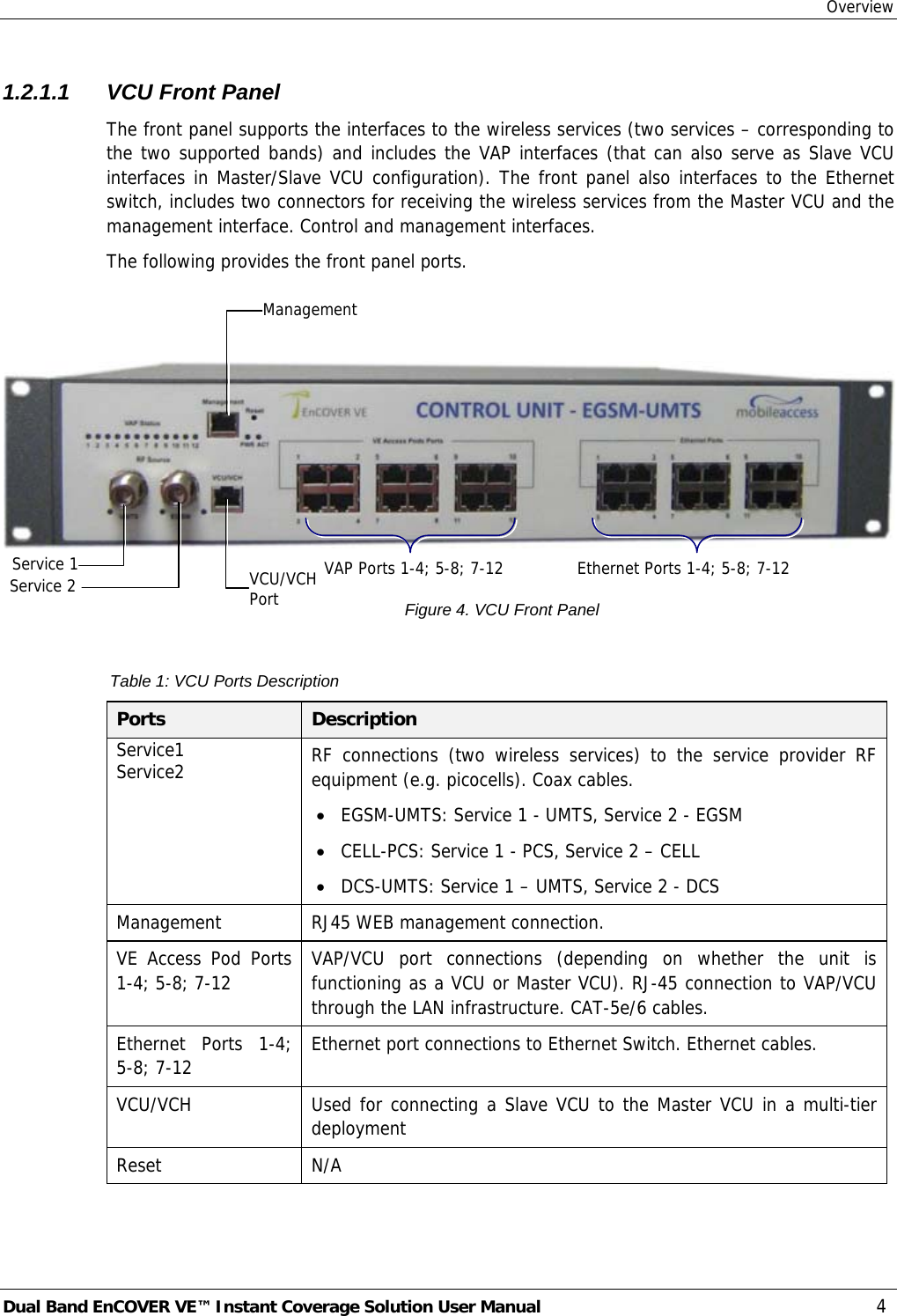
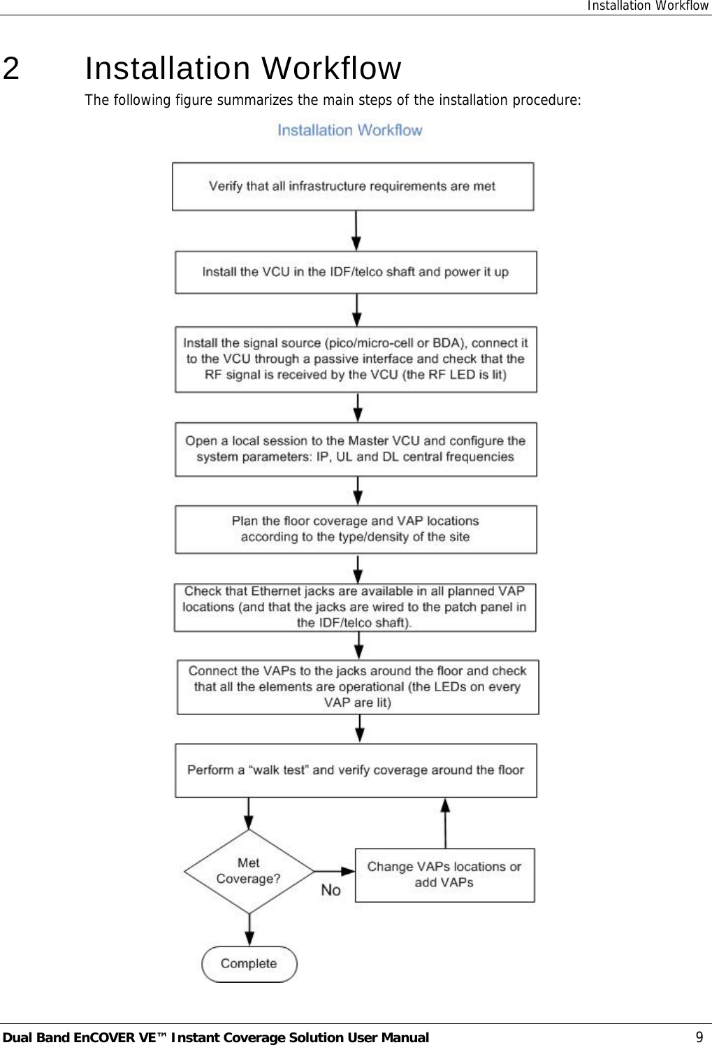
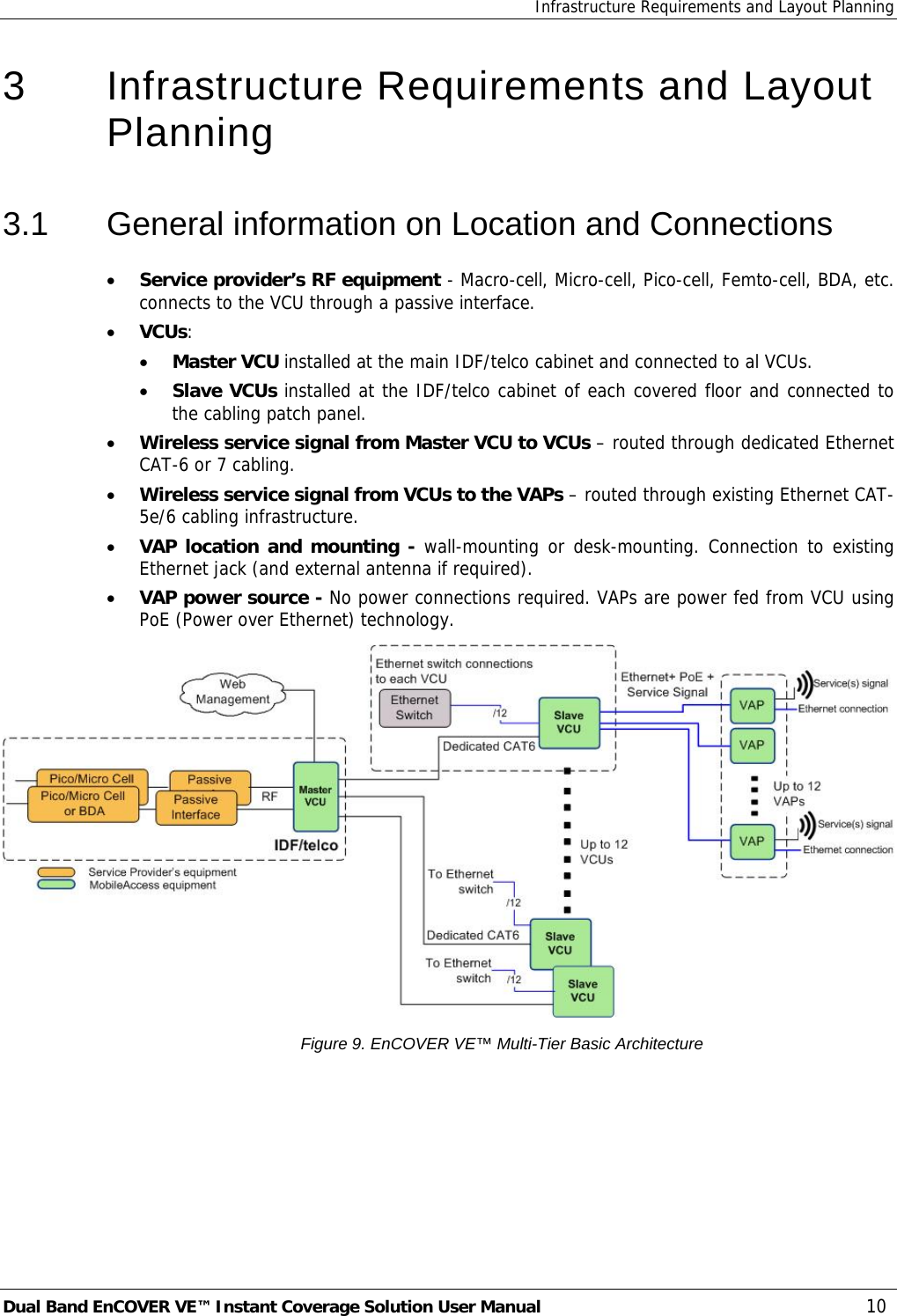
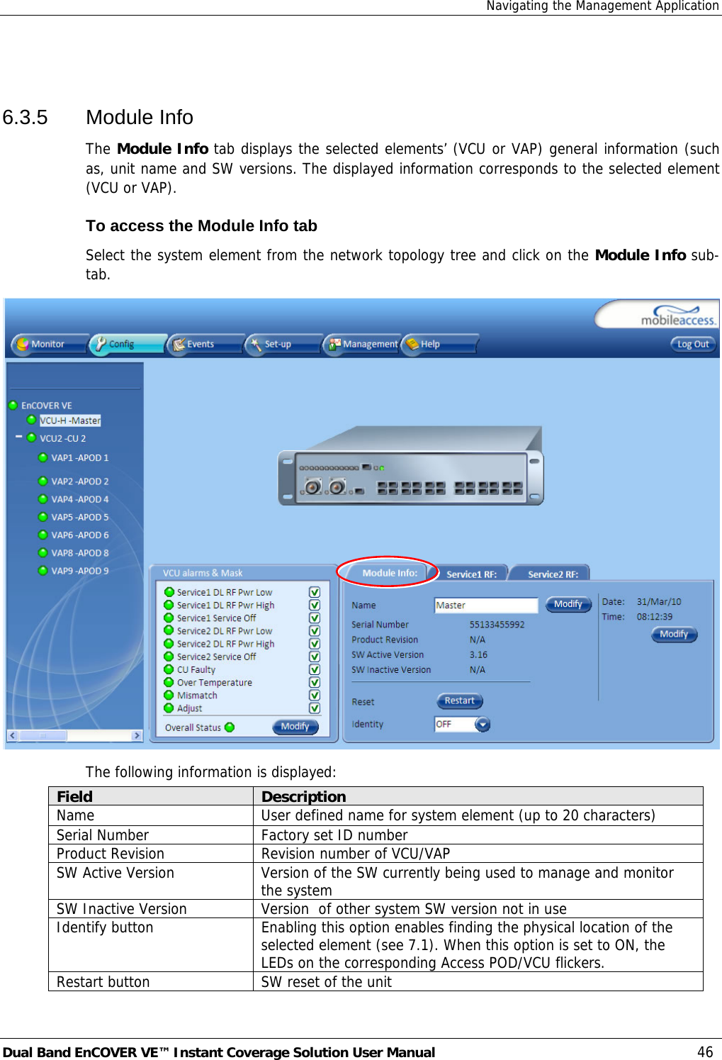
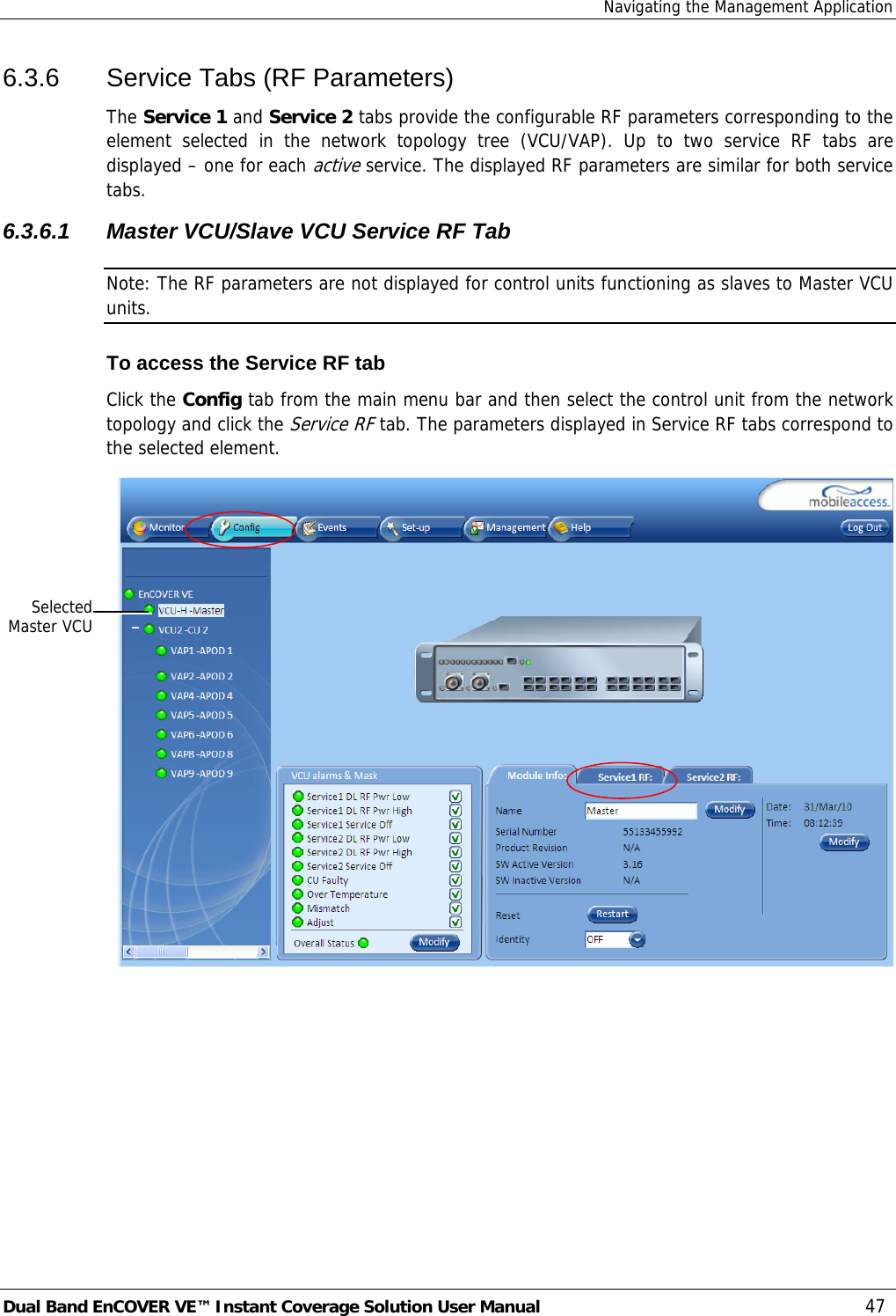
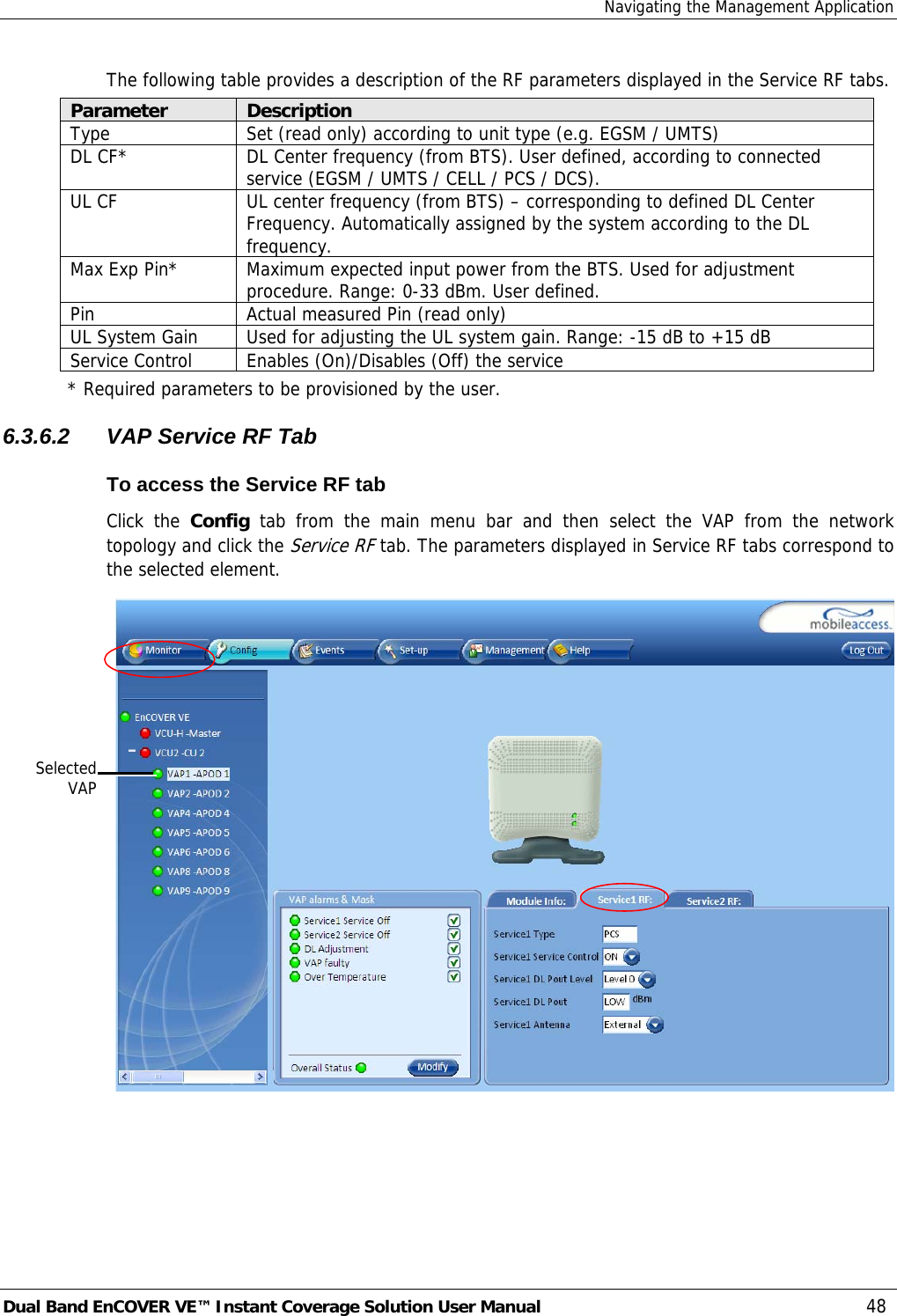
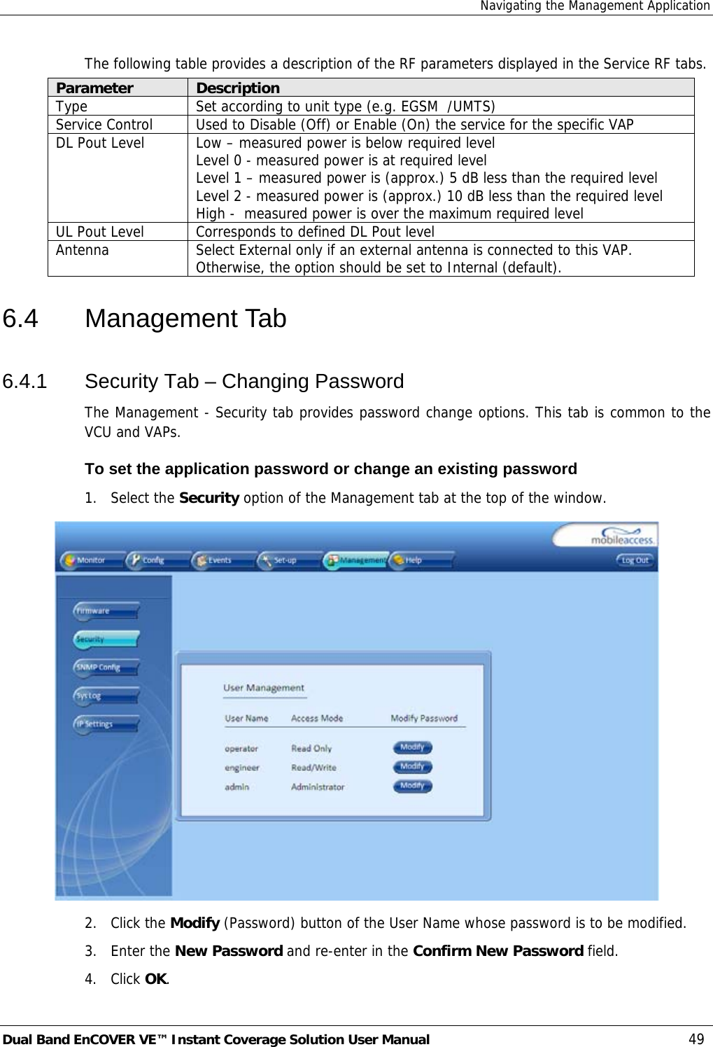
Corning Optical Communication VE-CELL-PCS12E EnCOVER VE CELL-PCS SYSTEM User Manual USERS MANUAL
Corning Optical Communication Wireless EnCOVER VE CELL-PCS SYSTEM USERS MANUAL
UserManual.wiki
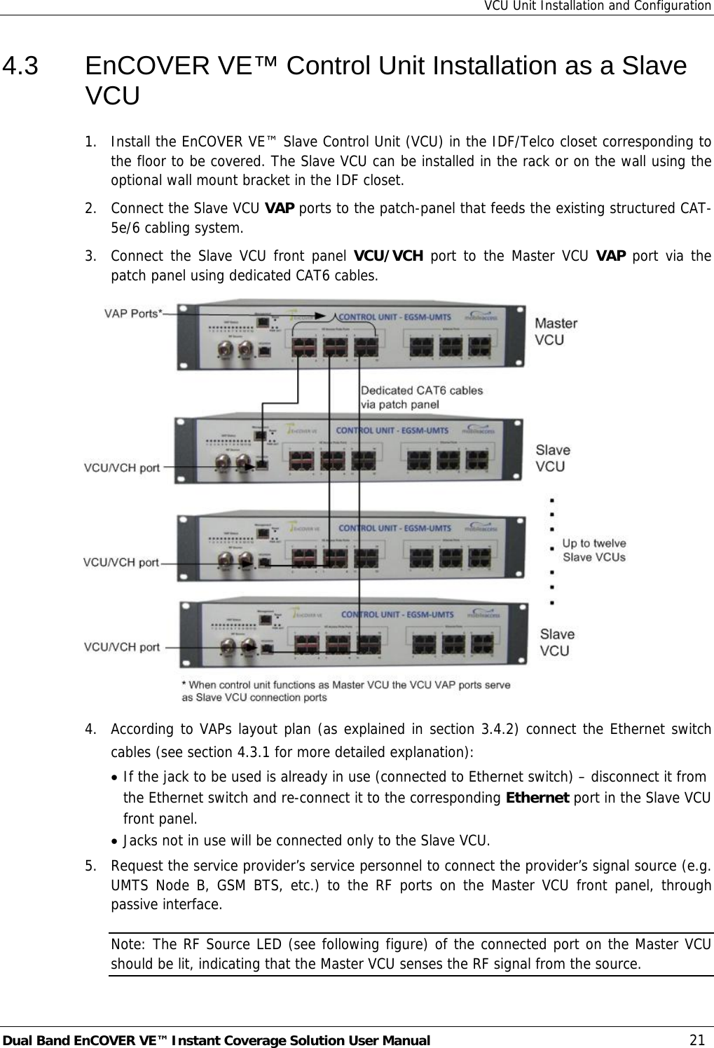
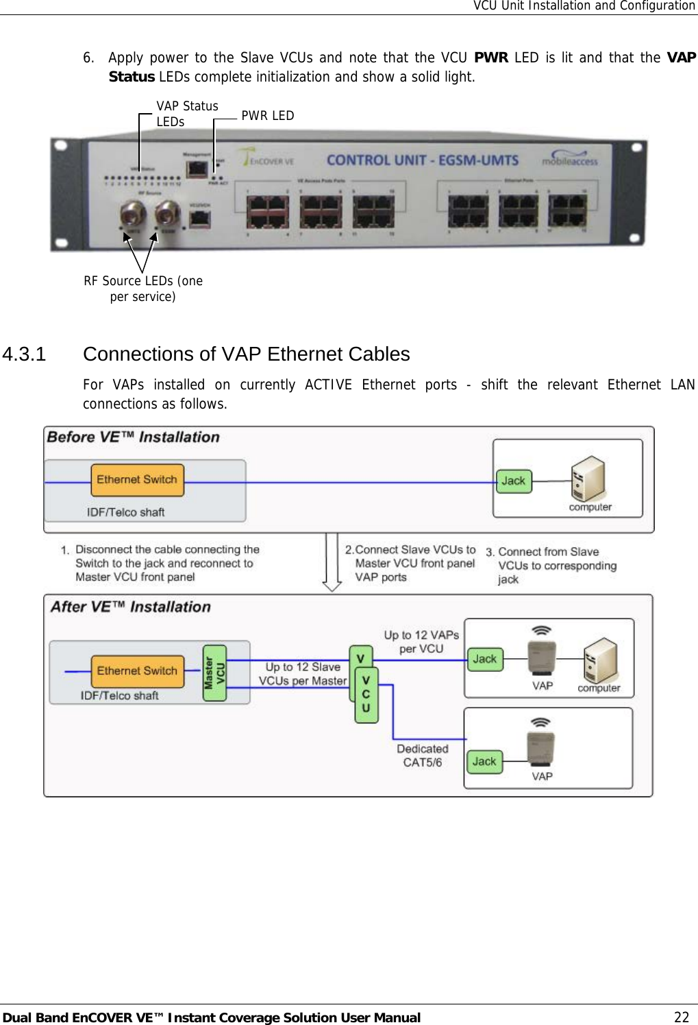
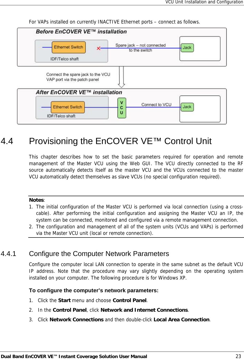
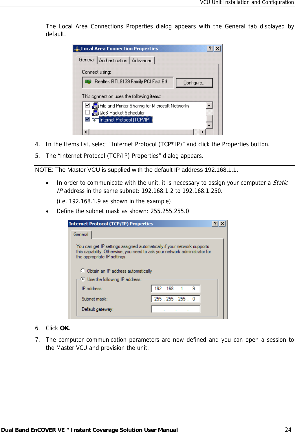
>
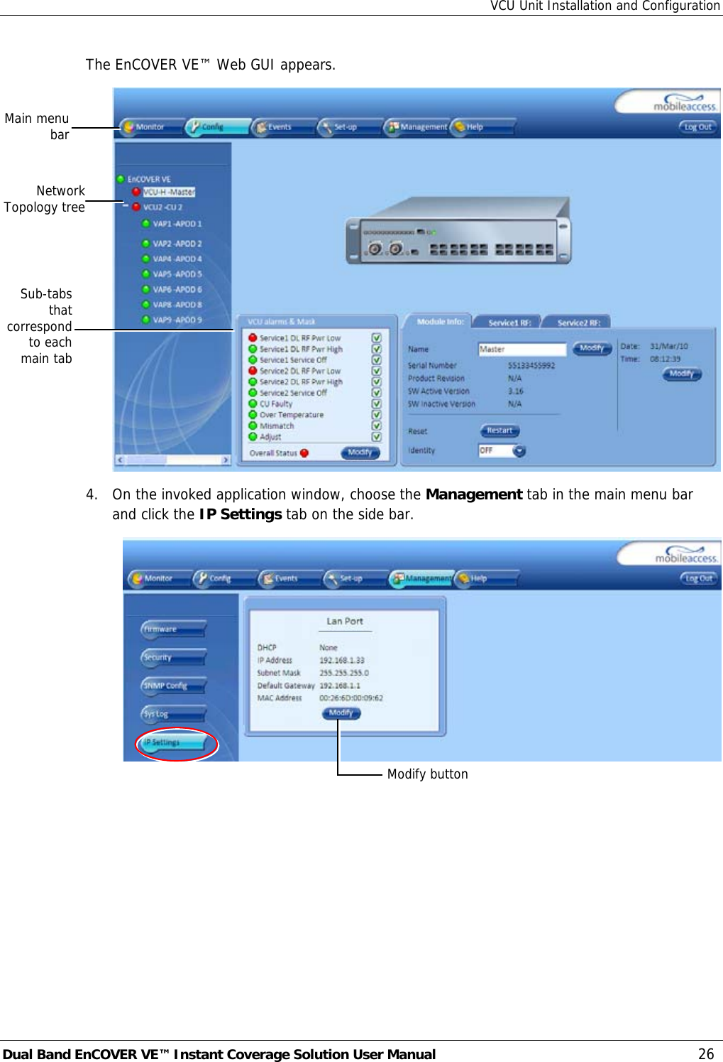
Corning Optical Communication
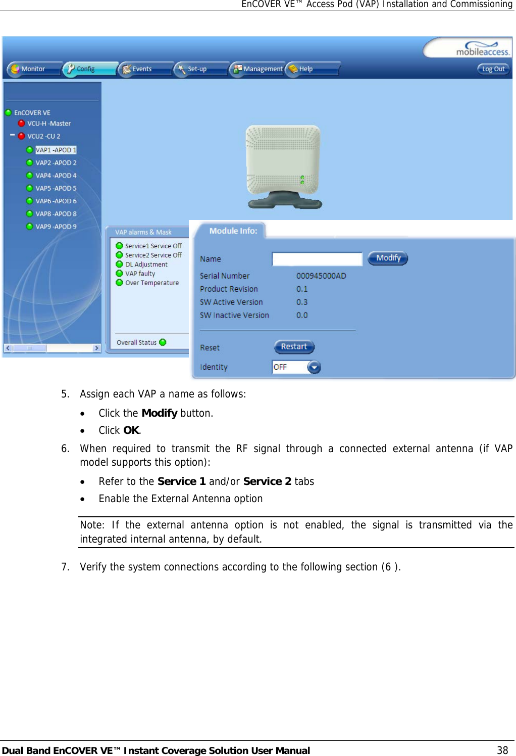
>
VE-CELL-PCS12E User Manual
>
USERS MANUAL
Contents
1.
USERS MANUAL
2.
Users Manual
USERS MANUAL
Navigation menu
Upload a User Manual
Namespaces
Wiki Guide
HTML
PDF
Info
Views
User Manual
Discussion / Help
Navigation