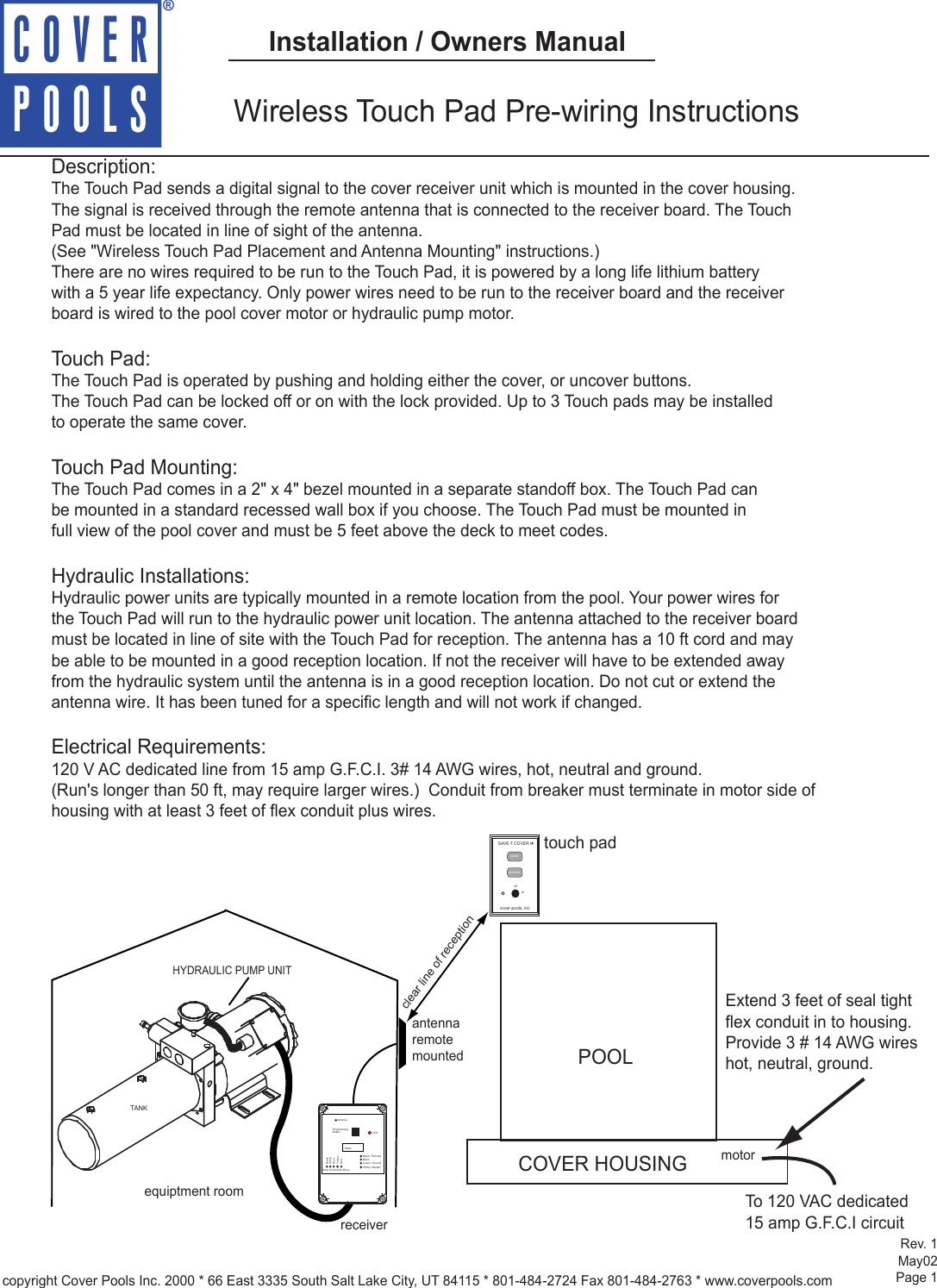
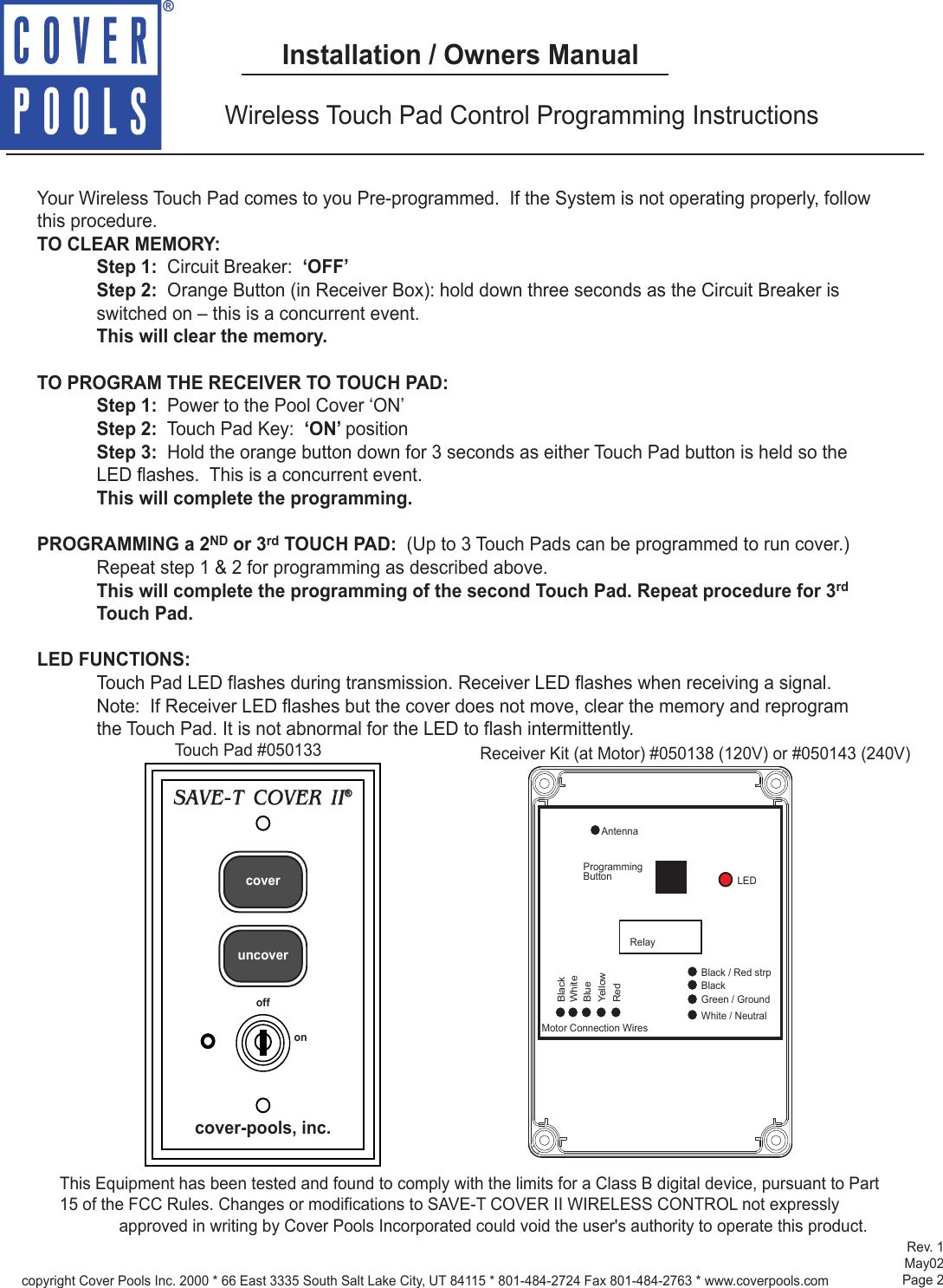
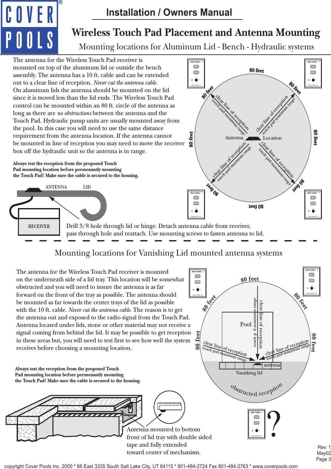
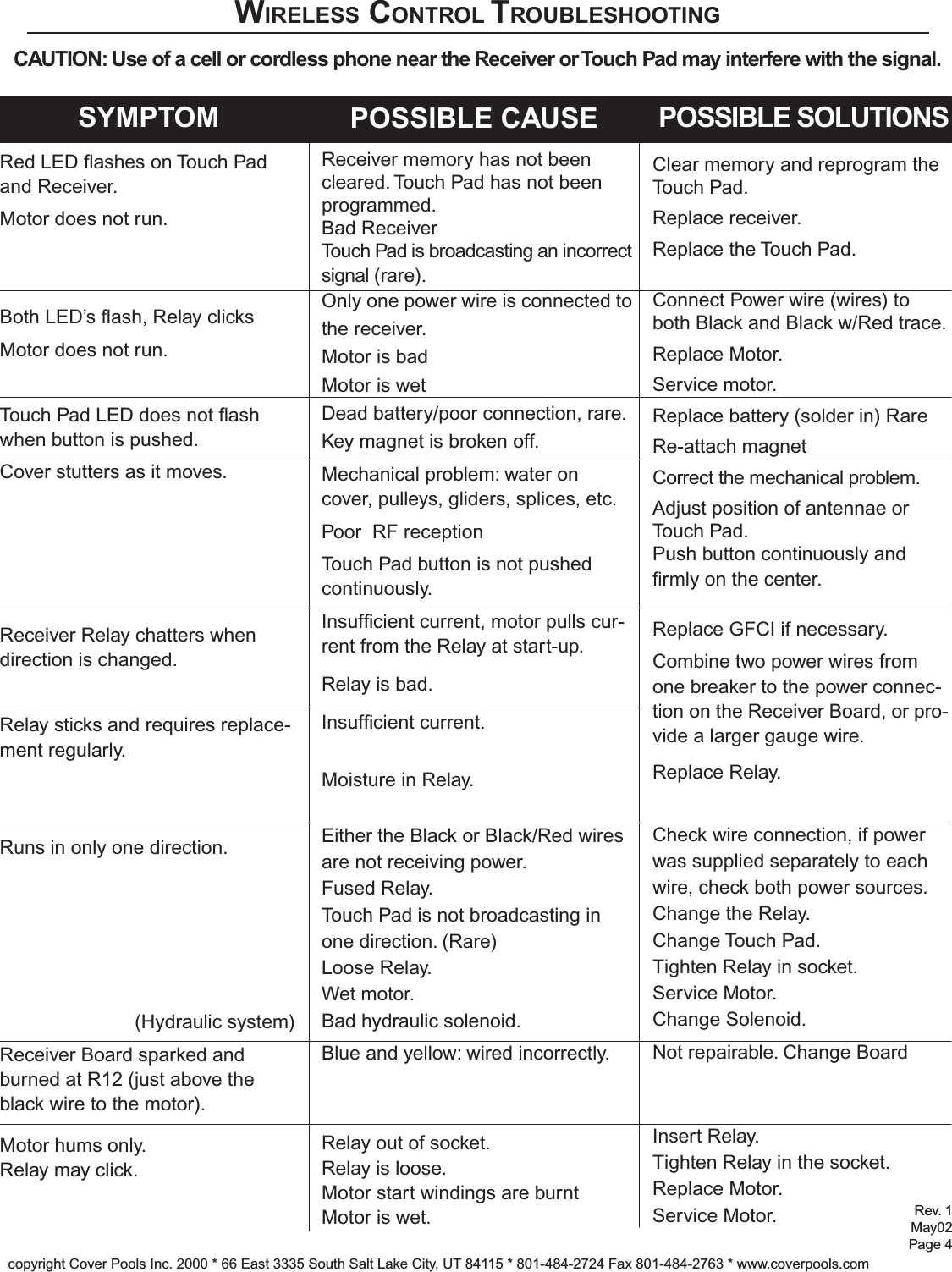
Cover Pools 50134 Model SAVE-T Cover II pool cover controller User Manual installation owners manual indd

Cover Pools, Inc. Model SAVE-T Cover II pool cover controller installation owners manual indd

manual with information

Wireless Touch Pad Pre-wiring InstructionsDescription:The Touch Pad sends a digital signal to the cover receiver unit which is mounted in the cover housing.The signal is received through the remote antenna that is connected to the receiver board. The Touch Pad must be located in line of sight of the antenna. (See "Wireless Touch Pad Placement and Antenna Mounting" instructions.)There are no wires required to be run to the Touch Pad, it is powered by a long life lithium batterywith a 5 year life expectancy. Only power wires need to be run to the receiver board and the receiver board is wired to the pool cover motor or hydraulic pump motor.Touch Pad:The Touch Pad is operated by pushing and holding either the cover, or uncover buttons. The Touch Pad can be locked off or on with the lock provided. Up to 3 Touch pads may be installed to operate the same cover. Touch Pad Mounting:The Touch Pad comes in a 2" x 4" bezel mounted in a separate standoff box. The Touch Pad can be mounted in a standard recessed wall box if you choose. The Touch Pad must be mounted in full view of the pool cover and must be 5 feet above the deck to meet codes. Hydraulic Installations:Hydraulic power units are typically mounted in a remote location from the pool. Your power wires for the Touch Pad will run to the hydraulic power unit location. The antenna attached to the receiver boardmust be located in line of site with the Touch Pad for reception. The antenna has a 10 ft cord and maybe able to be mounted in a good reception location. If not the receiver will have to be extended away from the hydraulic system until the antenna is in a good reception location. Do not cut or extend the antenna wire. It has been tuned for a specific length and will not work if changed.  Electrical Requirements:120 V AC dedicated line from 15 amp G.F.C.I. 3# 14 AWG wires, hot, neutral and ground. (Run's longer than 50 ft, may require larger wires.)  Conduit from breaker must terminate in motor side of housing with at least 3 feet of flex conduit plus wires. POOLCOVER HOUSING     Extend 3 feet of seal tight     flex conduit in to housing.     Provide 3 # 14 AWG wires     hot, neutral, ground.To 120 VAC dedicated15 amp G.F.C.I circuitmotorcopyright Cover Pools Inc. 2000 * 66 East 3335 South Salt Lake City, UT 84115 * 801-484-2724 Fax 801-484-2763 * www.coverpools.comHYDRAULIC PUMP UNITTANKantennaremotemountedreceiverequiptment roomSAVE-T COVER IIcoveruncoverRoffoncover-pools, inc.touch padclear line of receptionRev. 1May02Page 1Installation / Owners ManualAntennaProgrammingButton LEDBlack Green / Ground White / NeutralBlack / Red strpWhite BlueYellowBlack RedRelayMotor Connection Wires
Your Wireless Touch Pad comes to you Pre-programmed.  If the System is not operating properly, follow this procedure.TO CLEAR MEMORY:Step 1:  Circuit Breaker:  ‘OFF’Step 2:  Orange Button (in Receiver Box): hold down three seconds as the Circuit Breaker is switched on – this is a concurrent event.This will clear the memory.TO PROGRAM THE RECEIVER TO TOUCH PAD: Step 1:  Power to the Pool Cover ‘ON’Step 2:  Touch Pad Key:  ‘ON’ positionStep 3:  Hold the orange button down for 3 seconds as either Touch Pad button is held so the LED flashes.  This is a concurrent event.This will complete the programming. PROGRAMMING a 2ND or 3rd TOUCH PAD:  (Up to 3 Touch Pads can be programmed to run cover.) Repeat step 1 & 2 for programming as described above.This will complete the programming of the second Touch Pad. Repeat procedure for 3rd Touch Pad.LED FUNCTIONS:Touch Pad LED flashes during transmission. Receiver LED flashes when receiving a signal. Note:  If Receiver LED flashes but the cover does not move, clear the memory and reprogram the Touch Pad. It is not abnormal for the LED to flash intermittently.Wireless Touch Pad Control Programming Instructionscoveruncoveroffoncover-pools, inc.Touch Pad #050133 Receiver Kit (at Motor) #050138 (120V) or #050143 (240V)AntennaProgrammingButton LEDBlack Green / Ground White / NeutralBlack / Red strpWhite BlueYellowBlack RedRelayMotor Connection WiresRev. 1May02Page 2Installation / Owners ManualThis Equipment has been tested and found to comply with the limits for a Class B digital device, pursuant to Part15 of the FCC Rules. Changes or modifications to SAVE-T COVER II WIRELESS CONTROL not expressly approved in writing by Cover Pools Incorporated could void the user's authority to operate this product.  copyright Cover Pools Inc. 2000 * 66 East 3335 South Salt Lake City, UT 84115 * 801-484-2724 Fax 801-484-2763 * www.coverpools.com
Wireless Touch Pad Placement and Antenna MountingMounting locations for Aluminum Lid - Bench - Hydraulic systemsThe antenna for the Wireless Touch Pad receiver is mounted on top of the aluminum lid or outside the bench assembly. The antenna has a 10 ft. cable and can be extended out to a clear line of reception. Never cut the antenna cable.On aluminum lids the antenna should be mounted on the lid since it is moved less than the lid ends. The Wireless Touch Pad control can be mounted within an 80 ft. circle of the antenna as long as there are no obstructions between the antenna and the Touch Pad. Hydraulic pump units are usually mounted away from the pool. In this case you will need to use the same distance requirement from the antenna location. If the antenna cannot be mounted in line of reception you may need to move the receiver box off the hydraulic unit so the antenna is in range.Always test the reception from the proposed Touch Pad mounting location before permenantly mountingthe Touch Pad! Make sure the cable is secured to the housing. RECEIVERANTENNA LIDMounting locations for Vanishing Lid mounted antenna systemsAntenna mounted to bottom front of lid tray with double sidedtape and fully extended toward center of mechanism. The antenna for the Wireless Touch Pad receiver is mounted on the underneath side of a lid tray. This location will be somewhat obstructed and you will need to insure the antenna is as far forward on the front of the tray as possible. The antenna should be mounted as far towards the center trays of the lid as possible with the 10 ft. cable. Never cut the antenna cable. The reason is to get the antenna out and exposed to the radio signal from the Touch Pad.  Antenna located under lids, stone or other material may not receive a signal coming from behind the lid. It may be possible to get reception in these areas but, you will need to test first to see how well the system receives before choosing a mounting location.Antenna  80 feet 80 feet 80 feet 80 feet 80 feet 80 feet   80 feet80 feetSAVE-T COVER IIcoveruncoverRoffoncover-pools, inc.SAVE-T COVER IIcoveruncoverRoffoncover-pools, inc.SAVE-T COVER IIcoveruncoverRoffoncover-pools, inc.SAVE-T COVER IIcoveruncoverRoffoncover-pools, inc.Locationtouch pad maximum range clear line of receptiontouch pad maximum range clear line of receptiontouch pad maximum range clear line of receptiontouch pad maximum range clear line of receptionAlways test the reception from the proposed Touch Pad mounting location before permenantly mountingthe Touch Pad! Make sure the cable is secured to the housing. SAVE-T COVER IIcoveruncoverRoffoncover-pools, inc.SAVE-T COVER IIcoveruncoverRoffoncover-pools, inc.PoolVanishing lid80 feet80 feet80 feet80 feet80 feetantennaclear line of receptionclear line of receptionclear line of receptionSAVE-T COVER IIcoveruncoverRoffoncover-pools, inc.?obstructed receptiontouch pad maximum range touch pad maximum range touch pad maximum range Drill 3/8 hole through lid or hinge. Detach antenna cable from receiver, pass through hole and reattach. Use mounting screws to fasten antenna to lid.Rev. 1May02Page 3Installation / Owners Manualcopyright Cover Pools Inc. 2000 * 66 East 3335 South Salt Lake City, UT 84115 * 801-484-2724 Fax 801-484-2763 * www.coverpools.com
Rev. 1May02Page 4copyright Cover Pools Inc. 2000 * 66 East 3335 South Salt Lake City, UT 84115 * 801-484-2724 Fax 801-484-2763 * www.coverpools.comWIRELESS CONTROL TROUBLESHOOTINGCAUTION: Use of a cell or cordless phone near the Receiver or Touch Pad may interfere with the signal.SYMPTOM POSSIBLE CAUSE POSSIBLE SOLUTIONSRed LED ashes on Touch Pad and Receiver.Motor does not run.Both LED’s ash, Relay clicksMotor does not run.Touch Pad LED does not ash when button is pushed.Cover stutters as it moves.Receiver Relay chatters when direction is changed.Relay sticks and requires replace-ment regularly.Runs in only one direction.(Hydraulic system)Receiver Board sparked and burned at R12 (just above the black wire to the motor).Motor hums only.Relay may click.Receiver memory has not been cleared. Touch Pad has not been programmed.Bad ReceiverTouch Pad is broadcasting an incorrect signal (rare).Only one power wire is connected to the receiver.Motor is badMotor is wetDead battery/poor connection, rare.Key magnet is broken off.Mechanical problem: water on cover, pulleys, gliders, splices, etc.Poor  RF receptionTouch Pad button is not pushed continuously.Insufcient current, motor pulls cur-rent from the Relay at start-up.Relay is bad.Insufcient current.Moisture in Relay.Either the Black or Black/Red wires are not receiving power.Fused Relay.Touch Pad is not broadcasting in one direction. (Rare)Loose Relay.Wet motor.Bad hydraulic solenoid.Blue and yellow: wired incorrectly.Relay out of socket.Relay is loose.Motor start windings are burntMotor is wet.Clear memory and reprogram the Touch Pad.Replace receiver.Replace the Touch Pad.Connect Power wire (wires) to both Black and Black w/Red trace.Replace Motor.Service motor.Replace battery (solder in) RareRe-attach magnetCorrect the mechanical problem.Adjust position of antennae or Touch Pad.Push button continuously and rmly on the center.Replace GFCI if necessary.Combine two power wires from one breaker to the power connec-tion on the Receiver Board, or pro-vide a larger gauge wire.Replace Relay.Check wire connection, if power was supplied separately to each wire, check both power sources.Change the Relay.Change Touch Pad.Tighten Relay in socket.Service Motor.Change Solenoid.Not repairable. Change BoardInsert Relay.Tighten Relay in the socket.Replace Motor.Service Motor.
Rev. 1May02Page 5WIRELESS CONTROL TROUBLESHOOTINGTouch Pad Position Lead Touch Positions ReadingNo Button is pressedCOVER button pressedUNCOVER button pressedVoltmeter Common probe to WhiteOther probe to BlackOther probe to BlueOther probe to RedOther probe to YellowVoltmeter Common probe to WhiteOther probe to BlackOther probe to BlueOther probe to RedOther probe to YellowVoltmeter Common probe to WhiteOther probe to BlackOther probe to BlueOther probe to RedOther probe to Yellow115VAC115VAC8-9VAC8-9VAC115VAC8-9VAC8-9VAC115VAC115VAC115VAC8-9VAC8-9VACTo check a Wireless Receiver with VoltmeterWith Power ON and connected to the Receiver, a good Receiver will respond as follows:copyright Cover Pools Inc. 2000 * 66 East 3335 South Salt Lake City, UT 84115 * 801-484-2724 Fax 801-484-2763 * www.coverpools.comNote: This equipment has been tested and found to comply with the limits for a Class B digital device, pursuant to Part 15 of the FCC Rules. These limits are designed to provide reasonable protection against harmful interference in a residential installation. This equipment generates, uses and can radiate radio frequency energy and, if not installed and used in accordance with the instructions, may cause harmful interference to radio communications. However, there is no guarantee that interference will not occur in a particular installation. If this equipment does cause harmful interference to radio or television reception, which can be determined by turning the equipment off and on, the user is encouraged to try to correct the interference by one or more of the following measures:-Reorient or relocate the receiving antenna.-Increase the separation between the equipment and receiver.-Connect the equipment into an outlet on a circuit different from that to which the receiver  is connected.-Consult the dealer or an experienced radio/TV technician for help.

Navigation menu