Craftsman 107250060 User Manual TRACTOR Manuals And Guides 1203239L
User Manual: Craftsman 107250060 107250060 CRAFTSMAN TRACTOR - Manuals and Guides View the owners manual for your CRAFTSMAN TRACTOR #107250060. Home:Lawn & Garden Parts:Craftsman Parts:Craftsman TRACTOR Manual
Open the PDF directly: View PDF ![]() .
.
Page Count: 132 [warning: Documents this large are best viewed by clicking the View PDF Link!]

Operator's Manual
®
CTX Ga en Tractor
Model No.
107.250060 (26 Gross HP Briggs & Stratton with 52" Mower)
For answers to your questions about this
product, call Sears Craftsman Help Line
1-800=659-5917.
Sears Brands Management Corporation, Hoffman Estates, IL 60179 U.S.A.
Visit our Craftsman website: www.craftsman.com
1753802
Revision B

Front Cover ................................................................................................................. 1
Operator Safety .......................................................................................................... 4
Features and Controls ............................................................................................. 10
Operation .................................................................................................................. 14
Safety interlock System Tests ................................................................................. 14
Maintenance ............................................................................................................. 19
Troubleshooting ....................................................................................................... 30
Specifications ........................................................................................................... 32
Warranty .................................................................................................................... 33
Repair Protection Agreement .................................................................................. 34
Service Parts ....................................................................................................... PTS-1
Thank you for purchasing this quality-built CRAFTSMAN mower. We're pleased that you've placed your confidence
in the CRAFTSMAN brand. When operated and maintained according to the instructions in this manual, your
CRAFTSMAN product will provide many years of dependable service.
This manual contains safety information to make you aware of the hazards and risks associated with mowers and
how to avoid them. This product and its approved attachments/accessories are designed and intended only for lawn
work or snow removal and are not intended for any other purpose. It is important that you read and understand these
instructions thoroughly before attempting to start or operate this equipment. Save these original instructions for
future reference.
Where to Find Us
You never have to look far to find support and service for your CRAFTSMAN mower. There are authorized service
dealers in North America who provide quality service. You can contact Customer Service by phone at (800) 659-5917,
or locate a dealer on the Internet at www.craftsman.com.
Mower
Model Number
Serial Number
Engine
Model Type Trim
Date Code
Date Purchased
3

OperatingSafety
Congratulations on purchasing a superior-quality piece of lawn and
garden equipment. Our products are designed and manufactured to
meet or exceed all industry standards for safety.
Power equipment is only as safe as the operator. If it is misused, or
not properly maintained, it can be dangerous! Remember, you are
responsible for your safety and that of those around you.
Use common sense, and think through what you are doing. If you are
not sure that the task you are about to perform can be safely done
with the equipment you have chosen, ask a professional: contact
your local authorized dealer.
Readthe Manual
The operator's manual contains important safety information you
need to be aware of BEFORE you operate your unit as well as
DURING operation.
Safe operating techniques, an explanation of the product's features
and controls, and maintenance information is included to help you get
the most out of your equipment investment.
Be sure to completely read the Safety Rules and Information found on
the following pages. Also completely read the Operation section.
Children
Tragic accidents can occur with children. Do not allow them
anywhere near the area of operation. Children are often
attracted to the unit and mowing activity. Never assume that
children will remain where you last saw them. If there is a
risk that children may enter the area where you are mowing,
have another responsible adult watch them.
DO NOT GIVE CHILDREN RIDES ON THIS UNIT! This
encourages them to come near the unit in the future while it
is running, and they could be seriously hurt. They may then
approach the unit for a ride when you are not expecting it,
and you may run over them.
Reverse
Do not mow in reverse unless
absolutely necessary. Always look
down and behind before and while
traveling in reverse
even with the mower
blades disengaged.
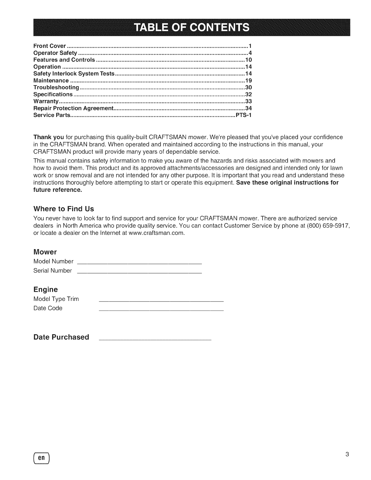
3.5ft
20.0 ft (6,0 m)
SlopeOperation
You could be seriously injured or even killed if you use this unit on too
steep an incline. Using the unit on a slope that is too steep or where you
don't have adequate traction can cause you to lose control or roll over.
A good rule of thumb is to not operate on any slope you cannot back up
(in 2-wheel drive mode). You should not operate on inclines with a slope
greater than a 3.5 foot rise over a 20 foot length. Always drive up and
down slopes: never cross the face.
Also note that the surface you are driving on can greatly impact stability
and control. Wet grass or icy pavement can seriously affect your ability to
control the unit.
If you feel unsure about operating the unit on an incline, don't do it. It's
not worth the risk.
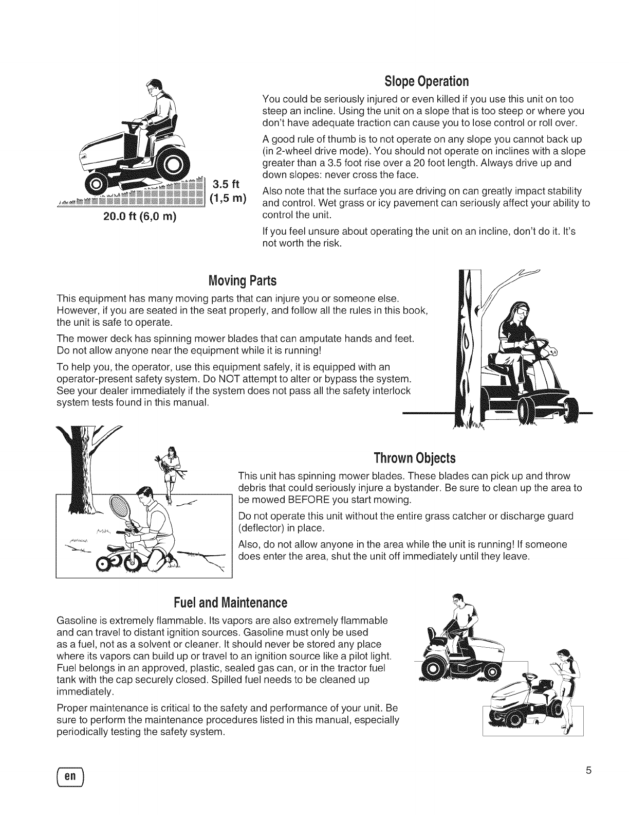
MovingParts
This equipment has many moving parts that can injure you or someone else.
However, if you are seated in the seat properly, and follow all the rules in this book,
the unit is safe to operate.
The mower deck has spinning mower blades that can amputate hands and feet.
Do not allow anyone near the equipment while it is running!
To help you, the operator, use this equipment safely, it is equipped with an
operator-present safety system. Do NOT attempt to alter or bypass the system.
See your dealer immediately if the system does not pass all the safety interlock
system tests found in this manual.
ThrownObjects
This unit has spinning mower blades. These blades can pick up and throw
debris that could seriously injure a bystander. Be sure to clean up the area to
be mowed BEFORE you start mowing.
Do not operate this unit without the entire grass catcher or discharge guard
(deflector) in place.
Also, do not allow anyone in the area while the unit is running! If someone
does enter the area, shut the unit off immediately until they leave.
Fueland Maintenance
Gasoline is extremely flammable. Its vapors are also extremely flammable
and can travel to distant ignition sources. Gasoline must only be used
as a fuel, not as a solvent or cleaner. It should never be stored any place
where its vapors can build up or travel to an ignition source like a pilot light.
Fuel belongs in an approved, plastic, sealed gas can, or in the tractor fuel
tank with the cap securely closed. Spilled fuel needs to be cleaned up
immediately.
Proper maintenance is critical to the safety and performance of your unit. Be
sure to perform the maintenance procedures listed in this manual, especially
periodically testing the safety system.
5
Readthesesafetyrulesandfollowthemclosely.Failuretoobeytheserulescouldresultinlossofcontrol
ofunit,severepersonalinjuryordeathtoyou,orbystanders,ordamageto propertyorequipment.
This mowing deck is capable of amputating hands and feet and throwing objects.
The triangle _ in text signifies important cautions or warnings which must be followed.
GENERAL OPERATION
1. Read, understand, and follow all instructions in the
manual and on the unit before starting.
2. Do not put hands or feet near rotating parts or under
the machine. Keep clear of the discharge opening at
all times.
3. Only allow responsible adults, who are familiar with
the instructions, to operate the unit (local regulations
can restrict operator age).
4. Clear the area of objects such as rocks, toys, wire,
etc., which could be picked up and thrown by the
blade(s).
5. Be sure the area is clear of other people before
mowing. Stop the unit if anyone enters the area.
6. Never carry passengers.
7. Do not mow in reverse unless absolutely necessary.
Always look down and behind before and while
travelling in reverse.
8. Never direct discharge material toward anyone. Avoid
discharging material against a wall or obstruction.
Material may ricochet back toward the operator. Stop
the blade(s) when crossing gravel surfaces.
9. Do not operate the machine without the entire grass
catcher, discharge guard (deflector), or other safety
devices in place.
10. Slow down before turning.
11. Never leave a running unit unattended. Always
disengage the PTO, set parking brake, stop engine,
and remove keys before dismounting.
12. Disengage blades (PTO) when not mowing. Shut off
engine and wait for all parts to come to a complete
stop before cleaning the machine, removing the grass
catcher, or unclogging the discharge guard.
13. Operate the machine only in daylight or good artificial
light.
14. Do not operate the unit while under the influence of
alcohol or drugs.
15 Watch for traffic when operating near or crossing
roadways.
16. Use extra care when loading or unloading the unit into
a trailer or truck.
17. Always wear eye protection when operating this unit.
18. Data indicates that operators, age 60 years and
above, are involved in a large percentage of power
equipment-related injuries. These operators should
evaluate their ability to operate the equipment safely
enough to protect themselves and others from injury.
19. Follow the manufacturer's recommendations for wheel
weights or counterweights.
20. Keep in mind the operator is responsible for accidents
occurring to other people or property.
21. All drivers should seek and obtain professional and
practical instruction.
22. Always wear substantial footwear and trousers. Never
operate when barefoot or wearing sandals.
23. Before using, always visually check that the blades
and blade hardware are present, intact, and secure.
Replace worn or damaged parts.
24. Disengage attachments before: refueling, removing
an attachment, making adjustments (unless the
adjustment can be made from the operator's position).
25. When the machine is parked, stored, or left
unattended, lower the cutting means unless a positive
mechanical lock is used.
26. Before leaving the operator's position for any reason,
engage the parking brake (if equipped), disengage the
PTO, stop the engine, and remove the key.
27. To reduce fire hazard, keep the unit free of grass,
leaves, & excess oil. Do not stop or park over dry
leaves, grass, or combustible materials.
TRANSPORTING AND STORAGE
1. When transporting the unit on an open trailer, make
sure it is facing forward, in the direction of travel. If the
unit is facing backwards, wind lift could damage the
unit.
2. Always observe safe refueling and fuel handling
practices when refueling the unit after transportation
or storage.
3. Never store the unit (with fuel) in an enclosed poorly
ventilated structure. Fuel vapors can travel to an
ignition source (such as a furnace, water heater, etc.)
and cause an explosion. Fuel vapor is also toxic to
humans and animals.
4. Always follow the engine manual instructions for
storage preparations before storing the unit for both
short and long term periods.
5. Always follow the engine manual instructions for
proper start-up procedures when returning the unit to
service.
6. Never store the unit or fuel container inside where
there is an open flame or pilot light, such as in a water
heater. Allow unit to cool before storing.
SLOPE OPERATION
Slopes are a major factor related to loss-of-control and tip-over
accidents, which can result insevere injury or death. Operation
on all slopes requires extra caution. If you cannot back up the
slope or if you feel uneasy on it, do not operate on it.
Control of a walk-behind or ride-on machine sliding on a
slope will not be regained by the application of the brake. The
main reasons for loss of control are: insufficient tire grip on
the ground, speed too fast, inadequate braking, the type of
machine is unsuitable for its task, lack of awareness of the
ground conditions, incorrect hitching and load distribution.
1. Mow up and down slopes, not across.
2. Watch for holes, ruts, or bumps. Uneven terrain could
overturn the unit. Tall grass can hide obstacles.
3. Choose a slow speed so that you will not have to stop
or change speeds while on the slope.
4. Do not mow on wet grass. Tires may loose traction.
5. Always keep unit in gear especially when traveling
down slopes. Do not shift to neutral and coast
downhill.
6. Avoid starting, stopping, or turning on a slope. If tires
lose traction, disengage the blade(s) and proceed
slowly straight down the slope.
7. Keep all movement on slopes slow and gradual. Do
not make sudden changes in speed or direction,
which could cause the machine to rollover.
8. Use extra care while operating machines with grass
catchers or other attachments; they can affect the
stability of the unit. Do not use on steeps slopes.
9. Do not try to stabilize the machine by putting your foot
on the ground (ride-on units).
10. Do not mow near drop-offs, ditches, or embankments.
The mower could suddenly turn over if a wheel is over
the edge of a cliff or ditch, or if an edge caves in.
11. Do not use grass catchers on steep slopes.
12. Do not mow slopes you cannot back up them.
13. See your authorized dealer/retailer for
recommendations of wheel weights or counterweights
to improve stability.
14. Remove obstacles such as rocks, tree limbs, etc.
15. Use slow speed. Tires may lose traction on slopes
even through the brakes are functioning properly.
16. Do not turn on slopes unless necessary, and then,
turn slowly and gradually downhill, if possible.
17. Four Wheel Drive Models: Four Wheel Drive improves
access to dangerously sloped terrain, increasing
the possibility of roll-over. If the machine stops while
going uphill, stop the blades and back down slowly.
Avoid sudden turns.
TOWED EQUIPMENT (RIDE-ON UNITS)
I. Tow only with a machine that has a hitch designed for
towing. Do not attach towed equipment except at the
hitch point.
2. Followthe manufacturer's recommendations for weight
limit for towed equipment and towingon slopes.
3. Never allow children or others in or on towed equipment.
4. On slopes, the weight of the towed equipment may
cause loss of traction and loss of control.
5. Travel slowly and allow extra distance to stop.
6. Do not shift to neutral and coast down hill.
WARNING
Never operate on slopes greater than 17.6 percent
(10 °) which is a rise of 3-1/2 feet (106 cm) vertically in
20 feet (607 cm) horizontally.
When operating on slopes use additional wheel
weights or counterweights. See your dealer/retailer
to determine which weights are available and
appropriate for your unit.
Select slow ground speed before driving onto
slope. In addition to front weights, use extra caution
when operating on slopes with rear-mounted grass
catchers.
Mow UP and DOWN the slope, never across the
face, use caution when changing directions and DO
NOT START OR STOP ON SLOPE.
CHILDREN
Tragic accidents can occur if the operator is not alert to the
presence of children. Children are often attracted to the unit
and the mowing activity. Never assume that children will
remain where you last saw them.
1. Keep children out of the mowing area and under the
watchful care of another responsible adult.
2. Be alert and turn unit off if children enter the area.
3. Before and during reverse operation, look behind and
down for small children.
4. Never carry children, even with the blade(s) off. They
may fall off and be seriously injured or interfere with
safe unit operation. Children who have been given
rides in the past may suddenly appear in the mowing
area for another ride and be run over or backed over
by the machine.
5. Never allow children to operate the unit.
6. Use extra care when approaching blind corners,
shrubs, trees, or other objects that may obscure
vision.
EMISSIONS
1. Engine exhaust from this product contains chemicals
known, in certain quantities, to cause cancer, birth
defects, or other reproductive harm.
2. Look for the relevant Emissions Durability Period and
Air Index information on the engine emissions label.
IGNITION SYSTEM
1. This spark ignition system complies with Canadian
ICES-002.
7
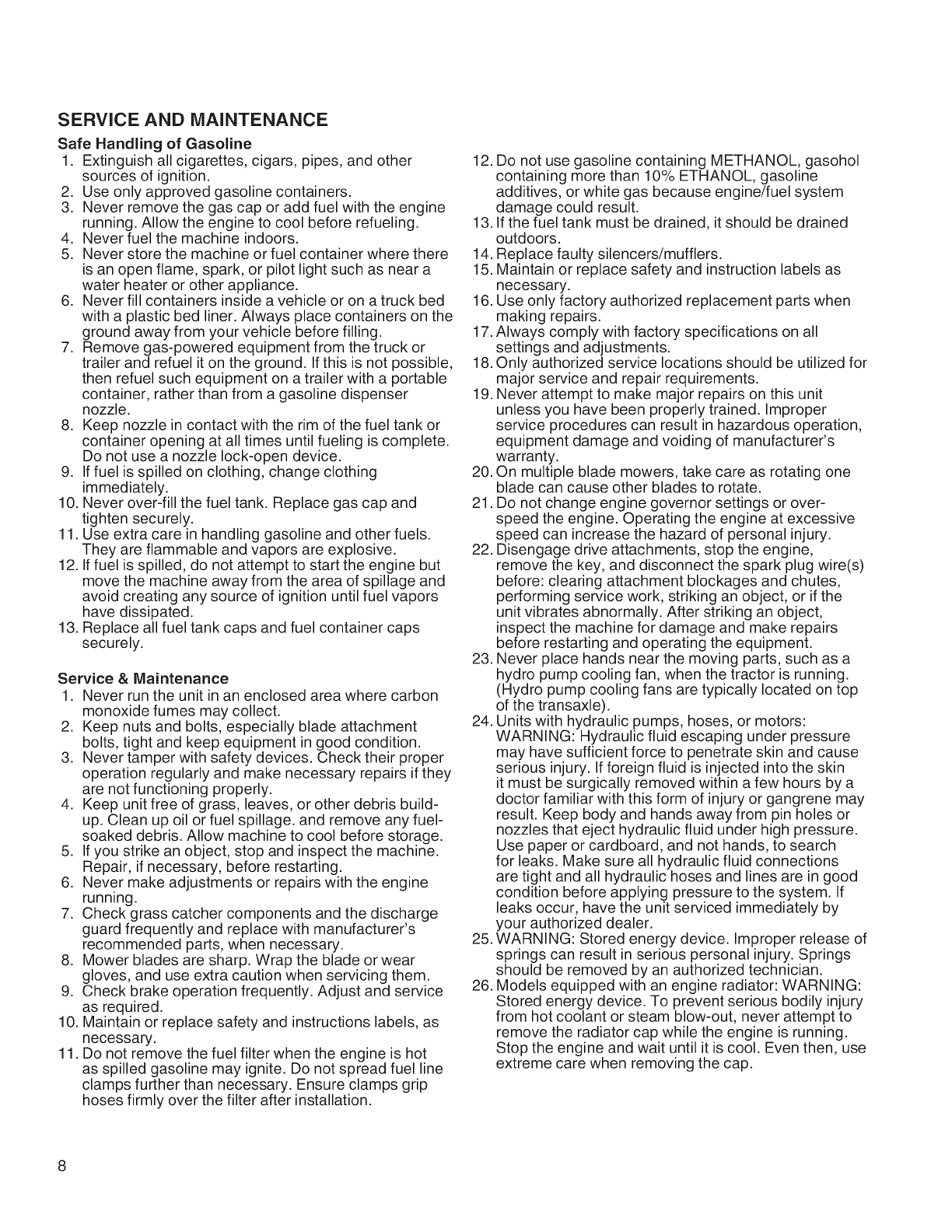
SERVICE AND MAINTENANCE
Safe Handling of Gasoline
1. Extinguish all cigarettes, cigars, pipes, and other
sources of ignition.
2. Use only approved gasoline containers.
3. Never remove the gas cap or add fuel with the engine
running. Allow the engine to cool before refueling.
4. Never fuel the machine indoors.
5. Never store the machine or fuel container where there
is an open flame, spark, or pilot light such as near a
water heater or other appliance.
6. Never fill containers inside a vehicle or on a truck bed
with a plastic bed liner. Always place containers on the
ground away from your vehicle before filling.
7. Remove gas-powered equipment from the truck or
trailer and refuel it on the ground. If this is not possible,
then refuel such equipment on a trailer with a portable
container, rather than from a gasoline dispenser
nozzle.
8. Keep nozzle in contact with the rim of the fuel tank or
container opening at all times until fueling is complete.
Do not use a nozzle lock-open device.
9. If fuel is spilled on clothing, change clothing
immediately.
10. Never over-fill the fuel tank. Replace gas cap and
tighten securely.
11. Use extra care in handling gasoline and other fuels.
They are flammable and vapors are explosive.
12. If fuel is spilled, do not attempt to start the engine but
move the machine away from the area of spillage and
avoid creating any source of ignition until fuel vapors
have dissipated.
13. Replace all fuel tank caps and fuel container caps
securely.
Service & Maintenance
1. Never run the unit in an enclosed area where carbon
monoxide fumes may collect.
2. Keep nuts and bolts, especially blade attachment
bolts, tight and keep equipment in good condition.
3. Never tamper with safety devices. Check their proper
operation regularly and make necessary repairs if they
are not functioning properly.
4. Keep unit free of grass, leaves, or other debris build-
up. Clean up oil or fuel spillage, and remove any fuel-
soaked debris. Allow machine to cool before storage.
5. If you strike an object, stop and inspect the machine.
Repair, if necessary, before restarting.
6. Never make adjustments or repairs with the engine
running.
7. Check grass catcher components and the discharge
guard frequently and replace with manufacturer's
recommended parts, when necessary.
8. Mower blades are sharp. Wrap the blade or wear
gloves, and use extra caution when servicing them.
9. Check brake operation frequently. Adjust and service
as required.
10. Maintain or replace safety and instructions labels, as
necessary.
11. Do not remove the fuel filter when the engine is hot
as spilled gasoline may ignite. Do not spread fuel line
clamps further than necessary. Ensure clamps grip
hoses firmly over the filter after installation.
12. Do not use gasoline containing METHANOL, gasohol
containing more than 10% ETHANOL, gasoline
additives, or white gas because engine/fuel system
damage could result.
13. If the fuel tank must be drained, it should be drained
outdoors.
14. Replace faulty silencers/mufflers.
15. Maintain or replace safety and instruction labels as
necessary.
16. Use only factory authorized replacement parts when
making repairs.
17. Always comply with factory specifications on all
settings and adjustments.
18. Only authorized service locations should be utilized for
major service and repair requirements.
19. Never attempt to make major repairs on this unit
unless you have been properly trained. Improper
service procedures can result in hazardous operation,
equipment damage and voiding of manufacturer's
warranty.
20. On multiple blade mowers, take care as rotating one
blade can cause other blades to rotate.
21. Do not change engine governor settings or over-
speed the engine. Operating the engine at excessive
speed can increase the hazard of personal injury.
22. Disengage drive attachments, stop the engine,
remove the key, and disconnect the spark plug wire(s)
before: clearing attachment blockages and chutes,
performing service work, striking an object, or if the
unit vibrates abnormally. After striking an object,
inspect the machine for damage and make repairs
before restarting and operating the equipment.
23. Never place hands near the moving parts, such as a
hydro pump cooling fan, when the tractor is running.
(Hydro pump cooling fans are typically located on top
of the transaxle).
24. Units with hydraulic pumps, hoses, or motors:
WARNING: Hydraulic fluid escaping under pressure
may have sufficient force to penetrate skin and cause
serious injury. If foreign fluid is injected into the skin
it must be surgically removed within a few hours by a
doctor familiar with this form of injury or gangrene may
result. Keep body and hands away from pin holes or
nozzles that eject hydraulic fluid under high pressure.
Use paper or cardboard, and not hands, to search
for leaks. Make sure all hydraulic fluid connections
are tight and all hydraulic hoses and lines are in good
condition before applying pressure to the system. If
leaks occur, have the unit serviced immediately by
your authorized dealer.
25. WARNING: Stored energy device. Improper release of
springs can result in serious personal injury. Springs
should be removed by an authorized technician.
26. Models equipped with an engine radiator: WARNING:
Stored energy device. To prevent serious bodily injury
from hot coolant or steam blow-out, never attempt to
remove the radiator cap while the engine is running.
Stop the engine and wait until it is cool. Even then, use
extreme care when removing the cap.
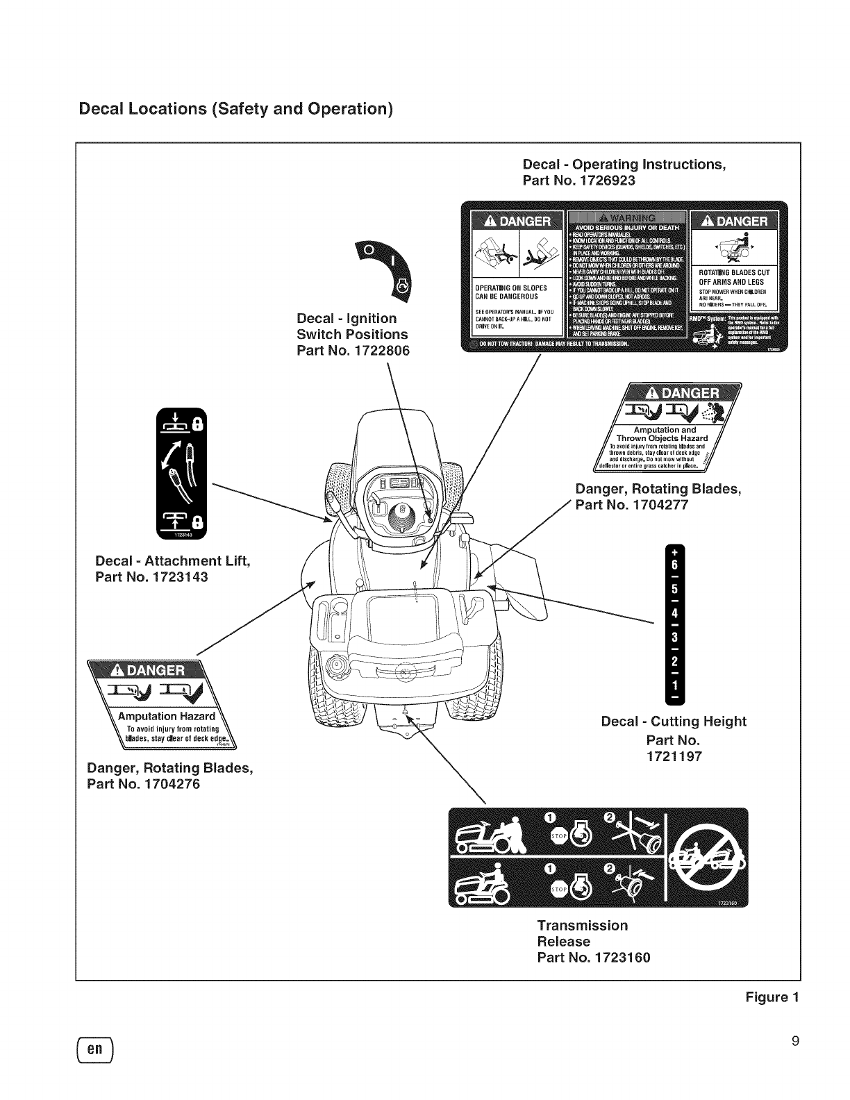
Decal Locations (Safety and Operation)
Decal - Operating instructions,
Part No. 1726923
Decal - ignition
Switch Positions
Part No. 1722808
TO avoid injury from rotating blades an] M
thrown debris, stay char ot deck edge
a_l_ discharge. DO not mow without
_d_e _et_ii! rentire gr_ss catcher in place.
Danger, Rotating Blades,
No. 1704277
Decal - Attachment Lift,
Part No. 1723143
reputation Hazard
To avoid injury from rotating \\
bllades,stay _lear ot deskedge;,_
Danger, Rotating Blades,
Part No. 1704276
Decal - Cutting Height
Part No.
1721197
Transmission
Release
Part No. 1723160
Figure 1
9
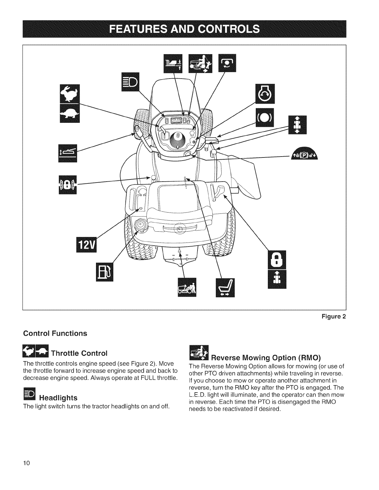
Figure2
Control Functions
__ Throttle Control
The throttle controls engine speed (see Figure 2). Move
the throttle forward to increase engine speed and back to
decrease engine speed, Always operate at FULL throttle,
Headlights
The light switch turns the tractor headlights on and off.
Reverse Mowing Option (RMO)
The Reverse Mowing Option allows for mowing (or use of
other PTO driven attachments) while traveling in reverse.
If you choose to mow or operate another attachment in
reverse, turn the RMO key after the PTO is engaged. The
L.E.D. light will illuminate, and the operator can then mow
in reverse. Each time the PTO is disengaged the RMO
needs to be reactivated if desired.
10
PTO Switch
The PTO (Power Take-Off) switch engages and
disengages attachments that use the PTO. To engage the
PTO, pull UP on the switch. Push DOWN to disengage.
Note that the operator must be seated firmly in the tractor
seat for the PTO to function.
Ignition Switch
The ignition switch starts and stops the engine, it has
three positions:
_OFF
H RUN
_START
Stops the engine and shuts off the
electrical system.
Allows the engine to run and powers the
electrical system.
Cranks the engine for starting.
NOTE: Never leave the ignition switch in the RUN
position with the engine stopped-this drains the battery.
Brake Pedal
Depressing the brake pedal applies the tractor brake.
Ground Speed Pedals
The tractor's forward ground speed is controlled by the
forward ground speed control pedal. The tractor's reverse
ground speed is controlled by the reverse ground speed
control pedal.
Depressing either pedal will increase ground speed. Note
that the further down the pedal is depressed, the faster
the tractor will travel.
Parking Brake
The parking brake knob is used to lock the parking brake
when the tractor is stopped. Fully depressing the brake
pedal and pulling up on the knob engages the parking
brake
Mower Height of Cut Adjustment
The cutting height is adjustable between 1.0" and 4.0"
(2,5 and 10,2 cm).
The cutting height adjustment switch controls the mower
cutting height. This same switch also controls the spout
rotator motor when a snowthrower is installed. The arrows
on the switch correspond to the direction of adjustment
(UP arrow raises cutting height, RIGHT arrow rotates
the spout right, etc). When the adjustment indicator has
reached the end of its travel, release the switch; holding
the switch down will damage the motor.
D Cruise Control
The cruise control is used to lock the ground speed
control in forward. Move the lever forward until the
desired ground speed is reached. To disengage the
cruise control move the lever back. In the event you need
to stop quickly, depressing the brake pedal will also return
the cruise control to neutral.
Seat Adjustment Lever
The seat can be adjusted forward and back. Move the
lever, position the seat as desired, and release the lever
to lock the seat into position.
Transmission Release Valve Lever
The transmission release valve lever deactivates the
transmission so that the tractor can be pushed by hand.
See Pushing the Tractor by Hand.
Fuel Tank
To remove the cap, turn counterclockwise. The fuel
gauge is part of the dashboard.
_ Power Outlet
The power outlet is 12V-DC. Accessory must be rated at
9 amps or less.
Differential Lock Pedal
Depressing this pedal locks the transmission differential,
locking both rear wheels into "drive".
Use this feature if the tractor is stuck because one
wheel is slipping. Engage the differential lock at slow
ground speeds only.
Attachment Lift Control Lever
When using the mower deck, lift the deck off the ground
while transporting to and from the job site. DO NOT cut
with the mower in the raised, transport position.
The attachment lift control lever raises and lowers
attachments that utilize the tractor's manual lift linkage.
To lower an attachment: pull the lever back slightly,
depress the release button, and push the lever forward
until it locks in the lowered position. To raise an
attachment: push the lever forward slightly, depress the
release button, then pull the lever back until it locks in the
raised position.
11
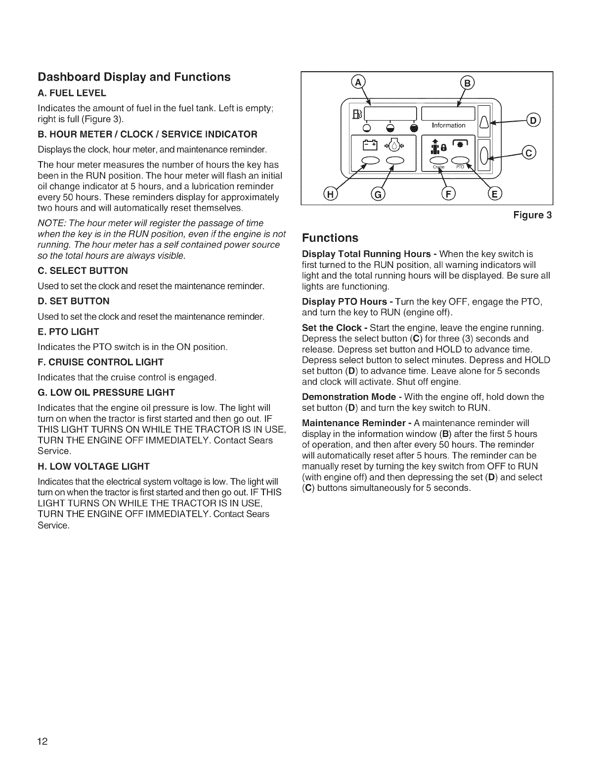
Dashboard Display and Functions
A. FUEL LEVEL
Indicates the amount of fuel in the fuel tank. Left is empty;
right is full (Figure 3).
B. HOUR METER /CLOCK /SERVICE INDICATOR
Displays the clock, hour meter, and maintenance reminder.
The hour meter measures the number of hours the key has
been in the RUN position. The hour meter will flash an initial
oil change indicator at 5 hours, and a lubrication reminder
every 50 hours. These reminders display for approximately
two hours and will automatically reset themselves.
NOTE: The hour meter will register the passage of time
when the key is in the RUN position, even ff the engine is not
running. The hour meter has a serf contained power source
so the total hours are always visible.
C. SELECT BUTTON
Used to set the clock and reset the maintenance reminder.
D. SET BUTTON
Used to set the clock and reset the maintenance reminder.
E. PTO LIGHT
Indicates the PTO switch is in the ON position.
F. CRUISE CONTROL LIGHT
Indicates that the cruise control is engaged.
G. LOW OIL PRESSURE LIGHT
Indicates that the engine oil pressure is low. The light will
turn on when the tractor is first started and then go out. IF
THIS LIGHT TURNS ON WHILE THE TRACTOR IS IN USE,
TURN THE ENGINE OFF IMMEDIATELY. Contact Sears
Service.
H. LOW VOLTAGE LIGHT
Indicates that the electrical system voltage is low. The light will
turn on when the tractor is first started and then go out. IF THIS
LIGHT TURNS ON WHILE THE TRACTOR IS IN USE,
TURN THE ENGINE OFF IMMEDIATELY. Contact Sears
Service.
O mnformation
;ir,
Figure 3
Functions
Display Total Running Hours - When the key switch is
first turned to the RUN position, all warning indicators will
light and the total running hours will be displayed. Be sure all
lights are functioning.
Display PTO Hours - Turn the key OFF, engage the PTO,
and turn the key to RUN (engine off).
Set the Clock - Start the engine, leave the engine running.
Depress the select button (C) for three (3) seconds and
release. Depress set button and HOLD to advance time.
Depress select button to select minutes. Depress and HOLD
set button (D) to advance time. Leave alone for 5 seconds
and clock will activate. Shut off engine.
Demonstration Mode - With the engine off, hold down the
set button (D) and turn the key switch to RUN.
Maintenance Reminder - A maintenance reminder will
display in the information window (B) after the first 5 hours
of operation, and then after every 50 hours. The reminder
will automatically reset after 5 hours. The reminder can be
manually reset by turning the key switch from OFF to RUN
(with engine off) and then depressing the set (D) and select
(C) buttons simultaneously for 5 seconds.
12
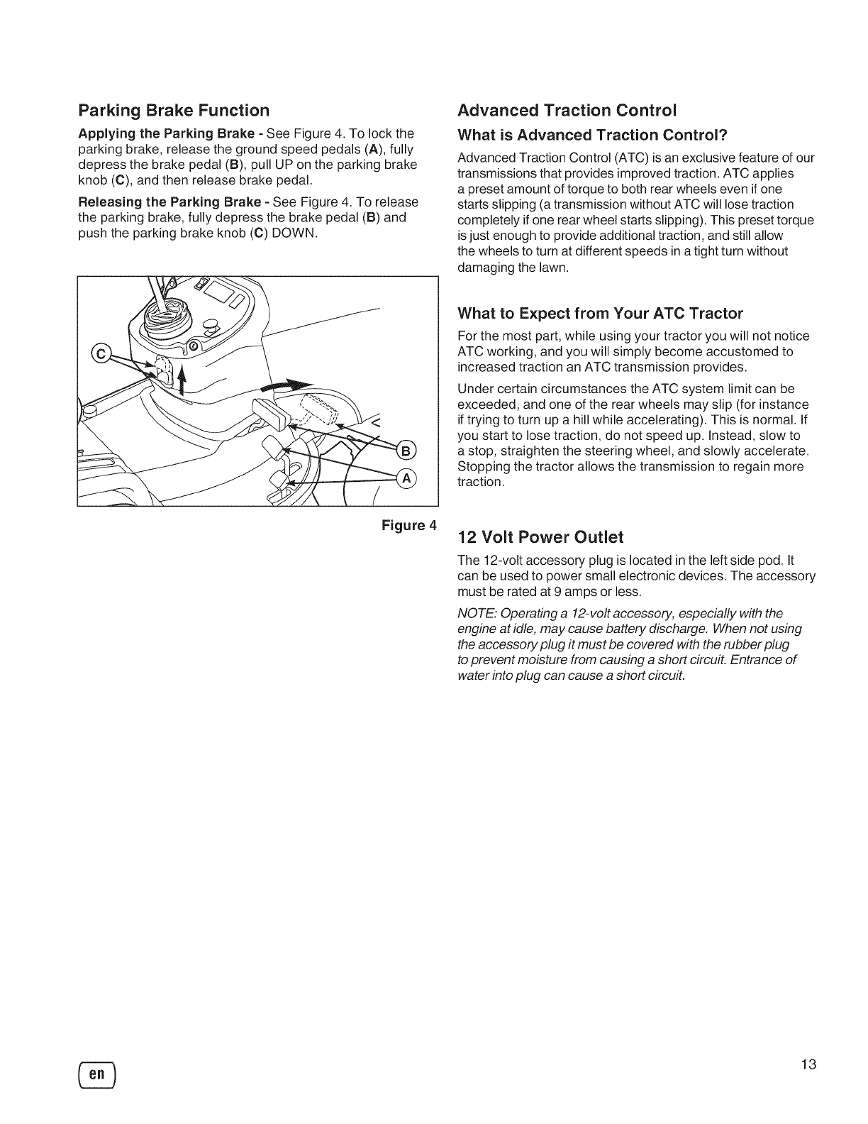
Parking Brake Function
Applying the Parking Brake - See Figure 4. To lock the
parking brake, release the ground speed pedals (A), fully
depress the brake pedal (B), pull UP on the parking brake
knob (C), and then release brake pedal.
Releasing the Parking Brake - See Figure 4. To release
the parking brake, fully depress the brake pedal (B) and
push the parking brake knob (C) DOWN.
Advanced Traction Control
What is Advanced Traction Control?
Advanced Traction Control (ATC) is an exclusive feature of our
transmissions that provides improved traction. ATC applies
a preset amount of torque to both rear wheels even if one
starts slipping (a transmission without ATC will lose traction
completely if one rear wheel starts slipping). This preset torque
is just enough to provide additional traction, and still allow
the wheels to turn at different speeds in a tight turn without
damaging the lawn.
What to Expect from Your ATC Tractor
For the most part, while using your tractor you will not notice
ATC working, and you will simply become accustomed to
increased traction an ATC transmission provides.
Under certain circumstances the ATC system limit can be
exceeded, and one of the rear wheels may slip (for instance
if trying to turn up a hill while accelerating). This is normal. If
you start to lose traction, do not speed up. Instead, slow to
a stop, straighten the steering wheel, and slowly accelerate.
Stopping the tractor allows the transmission to regain more
traction.
Figure 4 12 Volt Power Outlet
The 12-volt accessory plug is located in the left side pod. It
can be used to power small electronic devices. The accessory
must be rated at 9 amps or less.
NOTE: Operating a 12-volt accessory, especially with the
engine at idle, may cause battery discharge. When not using
the accessory plug it must be covered with the rubber plug
to prevent moisture from causing a short circuit. Entrance of
water into plug can cause a short circuit.
13
Safety Interlock System Tests
This unit is equipped with safety interlock switches and
other safety devices. These safety systems are present
for your safety: do not attempt to bypass safety switches,
and never tamper with safety devices.
WARNING
If the unit does not pass a safety test, do not
operate it. See your authorized dealer.
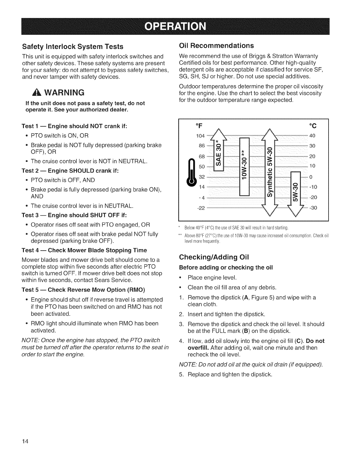
Oil Recommendations
We recommend the use of Briggs & Stratton Warranty
Certified oils for best performance. Other high-quality
detergent oils are acceptable if classified for service SF,
SG, SH, SJ or higher. Do not use special additives.
Outdoor temperatures determine the proper oil viscosity
for the engine. Use the chart to select the best viscosity
for the outdoor temperature range expected.
Test 1 -- Engine should NOT crank if:
• PTO switch is ON, OR
• Brake pedal is NOT fully depressed (parking brake
OFF), OR
• The cruise control lever is NOT in NEUTRAL.
Test 2 -- Engine SHOULD crank if:
• PTO switch is OFF, AND
• Brake pedal is fully depressed (parking brake ON),
AND
° The cruise control lever is in NEUTRAL.
Test 3 -- Engine should SHUT OFF if:
• Operator rises off seat with PTO engaged, OR
• Operator rises off seat with brake pedal NOT fully
depressed (parking brake OFF).
Test 4-- Check Mower Blade Stopping Time
Mower blades and mower drive belt should come to a
complete stop within five seconds after electric PTO
switch is turned OFF. If mower drive belt does not stop
within five seconds, contact Sears Service.
Test 5 -- Check Reverse Mow Option (RMO)
• Engine should shut off if reverse travel is attempted
if the PTO has been switched on and RMO has not
been activated.
• RMO light should illuminate when RMO has been
activated.
NOTE: Once the engine has stopped, the PTO switch
must be turned off after the operator retums to the seat in
order to start the engine.
°C
o! ...................3o
03|
].......... 20
°!5
t=
c ................. !0
t_ €
Z2;,=3O
Below40°F (4°C)the useof SAE30will result inhardstarting.
** Above80°F (27°0)the useof 10W-30maycauseincreased0il c0nsumpti0n.Check0il
levelmorefrequently.
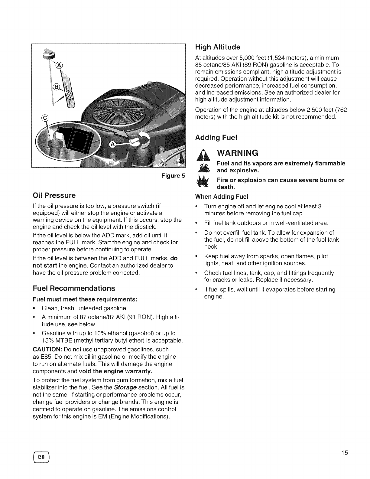
Checking/Adding Oil
Before adding or checking the oil
•Place engine level.
•Clean the oil fill area of any debris.
1. Remove the dipstick (A, Figure 5) and wipe with a
clean cloth.
2. Insert and tighten the dipstick.
3. Remove the dipstick and check the oil level. It should
be at the FULL mark (B) on the dipstick.
4. If low, add oil slowly into the engine oil fill (C). Do not
overfill. After adding oil, wait one minute and then
recheck the oil level.
NOTE: Do not add oil at the quick oil drain (if equipped).
5. Replace and tighten the dipstick.
14
High Altitude
At altitudes over 5,000 feet (1,524 meters), a minimum
85 octane/85 AKI (89 RON) gasoline is acceptable. To
remain emissions compliant, high altitude adjustment is
required. Operation without this adjustment will cause
decreased performance, increased fuel consumption,
and increased emissions. See an authorized dealer for
high altitude adjustment information.
Operation of the engine at altitudes below 2,500 feet (762
meters) with the high altitude kit is not recommended.
Figure 5
Oil Pressure
If the oil pressure is too low, a pressure switch (if
equipped) will either stop the engine or activate a
warning device on the equipment. If this occurs, stop the
engine and check the oil level with the dipstick.
If the oil level is below the ADD mark, add oil until it
reaches the FULL mark. Start the engine and check for
proper pressure before continuing to operate.
If the oil level is between the ADD and FULL marks, do
not start the engine. Contact an authorized dealer to
have the oil pressure problem corrected.
Fuel Recommendations
Fuel must meet these requirements:
• Clean, fresh, unleaded gasoline.
• A minimum of 87 octane/87 AKI (91 RON). High alti-
tude use, see below.
• Gasoline with up to 10% ethanol (gasohol) or up to
15% MTBE (methyl tertiary butyl ether) is acceptable.
CAUTION: Do not use unapproved gasolines, such
as E85. Do not mix oil in gasoline or modify the engine
to run on alternate fuels. This will damage the engine
components and void the engine warranty.
To protect the fuel system from gum formation, mix a fuel
stabilizer into the fuel. See the Storage section. All fuel is
not the same. If starting or performance problems occur,
change fuel providers or change brands. This engine is
certified to operate on gasoline. The emissions control
system for this engine is EM (Engine Modifications).
Adding Fuel
WARNING
Fuel and its vapors are extremely flammable
and explosive.
Fire or explosion can cause severe burns or
death.
When Adding Fuel
° Turn engine off and let engine cool at least 3
minutes before removing the fuel cap.
° Fill fuel tank outdoors or in well-ventilated area.
•Do not overfill fuel tank. To allow for expansion of
the fuel, do not fill above the bottom of the fuel tank
neck.
•Keep fuel away from sparks, open flames, pilot
lights, heat, and other ignition sources.
•Check fuel lines, tank, cap, and fittings frequently
for cracks or leaks. Replace if necessary.
•If fuel spills, wait until it evaporates before starting
engine.
15
.
.
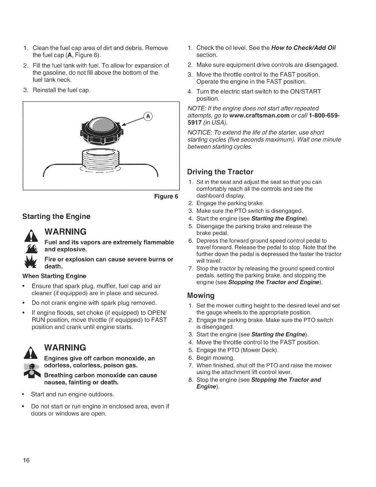
Clean the fuel cap area of dirt and debris. Remove
the fuel cap (A, Figure 6).
Fill the fuel tank with fuel. To allow for expansion of
the gasoline, do not fill above the bottom of the
fuel tank neck.
3. Reinstall the fuel cap.
Figure 6
Starting the Engine
WARNING
Fuel and its vapors are extremely flammable
and explosive.
Fire or explosion can cause severe burns or
death.
When Starting Engine
• Ensure that spark plug, muffler, fuel cap and air
cleaner (if equipped) are in place and secured.
• Do not crank engine with spark plug removed.
• If engine floods, set choke (if equipped) to OPEN/
RUN position, move throttle (if equipped) to FAST
position and crank until engine starts.
e
e
WARNING
Engines give off carbon monoxide, an
odorless, colorless, poison gas.
Breathing carbon monoxide can cause
nausea, fainting or death.
Start and run engine outdoors.
Do not start or run engine in enclosed area, even if
doors or windows are open.
1. Check the oil level. See the How to Check/Add Off
section.
2. Make sure equipment drive controls are disengaged.
3. Move the throttle control to the FAST position.
Operate the engine in the FAST position.
4. Turn the electric start switch to the ON/START
position.
NOTE: If the engine does not start after repeated
attempts, go to www.craftsman.com or call 1-800-659 =
5917 (in USA),
NOTICE: To extend the life of the starter, use short
starting cycles (five seconds maximum). Wait one minute
between starting cycles.
Driving the Tractor
1. Sit in the seat and adjust the seat so that you can
comfortably reach all the controls and see the
dashboard display.
2. Engage the parking brake.
3. Make sure the PTO switch is disengaged.
4. Start the engine (see Starting the Engine).
5. Disengage the parking brake and release the
brake pedal.
6. Depress the forward ground speed control pedal to
travel forward. Release the pedal to stop. Note that the
further down the pedal is depressed the faster the tractor
will travel.
7. Stop the tractor by releasing the ground speed control
pedals, setting the parking brake, and stopping the
engine (see Stopping the Tractor and Engine).
Mowing
1. Set the mower cutting height to the desired level and set
the gauge wheels to the appropriate position.
2. Engage the parking brake. Make sure the PTO switch
is disengaged.
3. Start the engine (see Starting the Engine).
4. Move the throttle control to the FAST position.
5. Engage the PTO (Mower Deck).
6. Begin mowing.
7. When finished, shut off the PTO and raise the mower
using the attachment lift control lever.
8. Stop the engine (see Stopping the Traetorand
Engine).
16
WARNING
The engine will shut off if the reverse ground speed
pedal is depressed while the PTO is on and the
RMO has not been activated. The operator should
always turn the PTO off prior to driving across
on roads, paths or any area that maybe used by
other vehicles. Sudden loss of drive could create a
hazard.
WARNING
Mowing in reverse can be hazardous to bystanders.
Tragic accidents can occur if the operator is not
alert to the presence of children. Never activate
RMO if children are present. Children are often
attracted to the unit and the mowing activity.
Mowing in Reverse (RMO)
If an operator chooses to mow in reverse, the RMO system
can be used. To use the Reverse Mowing Option (RMO) turn
the RMO key after the PTO is engaged. The L.E.D. light will
illuminate, and the operator can then mow in reverse. Each
time the PTO is engaged the RMO needs to be reactivated if
desired. The key should be removed to restrict access to the
RMO feature.
Attachment Operation in Reverse
If an operator chooses to operate a PTO driven attachment
in reverse, the RMO system can be used. To use the
Reverse Mowing Option (RMO) turn the RMO key after
the PTO is engaged. The L.E.D. light will illuminate, and
the operator can then operate the attachment in reverse.
Each time the PTO is disengaged the RMO needs to be
reactivated if desired. The key should be removed to restrict
access to the RMO feature.
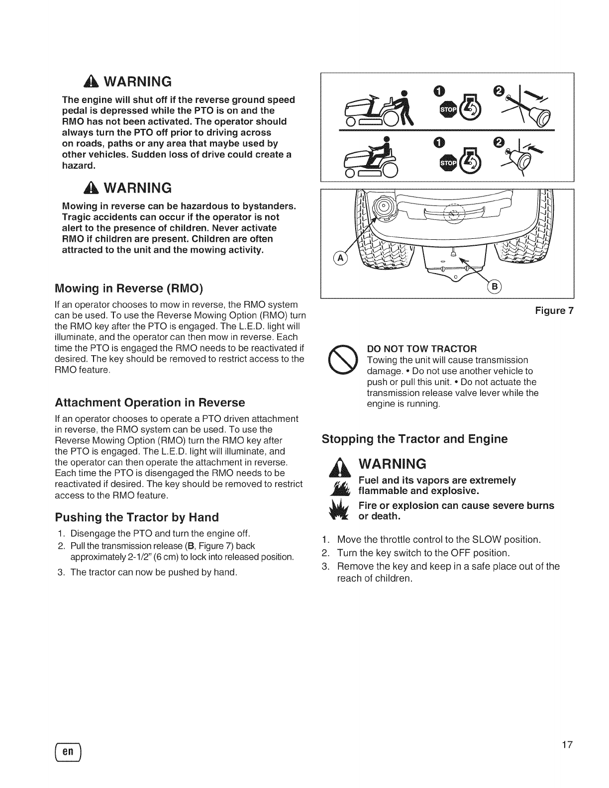
Pushing the Tractor by Hand
1. Disengage the PTO and turn the engine off.
2. Pull the transmission release (B, Figure 7) back
approximately 2-1/2" (6 cm) to lock into released position.
3. The tractor can now be pushed by hand.
O
...j
Figure 7
®DO NOT TOW TRACTOR
Towing the unit will cause transmission
damage. = Do not use another vehicle to
push or pull this unit. = Do not actuate the
transmission release valve lever while the
engine is running.
Stopping the Tractor and Engine
WARNING
Fuel and its vapors are extremely
flammable and explosive.
Fire or explosion can cause severe burns
or death.
1. Move the throttle control to the SLOW position.
2. Turn the key switch to the OFF position.
3. Remove the key and keep in a safe place out of the
reach of children,
17
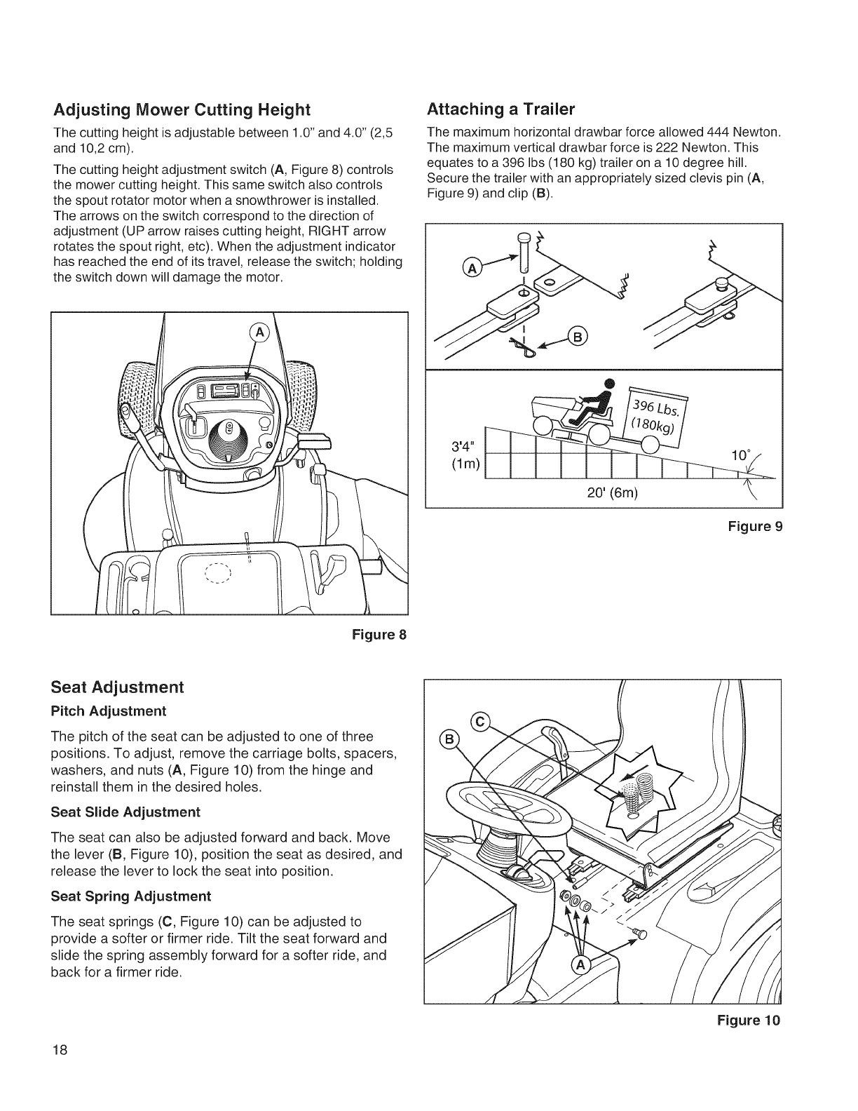
Adjusting Mower Cutting Height
The cutting height is adjustable between 1.0" and 4.0" (2,5
and 10,2 cm).
The cutting height adjustment switch (A, Figure 8) controls
the mower cutting height. This same switch also controls
the spout rotator motor when a snowthrower is installed.
The arrows on the switch correspond to the direction of
adjustment (UP arrow raises cutting height, RIGHT arrow
rotates the spout right, etc). When the adjustment indicator
has reached the end of its travel, release the switch; holding
the switch down will damage the motor.
Figure 8
Attaching aTrailer
The maximum horizontal drawbar force allowed 444 Newton.
The maximum vertical drawbar force is 222 Newton. This
equates to a 396 Ibs (180 kg) trailer on a 10 degree hill.
Secure the trailer with an appropriately sized clevis pin (A,
Figure 9) and clip (B).
J
,4,,
(lm)
Figure 9
Seat Adjustment
Pitch Adjustment
The pitch of the seat can be adjusted to one of three
positions. To adjust, remove the carriage bolts, spacers,
washers, and nuts (A, Figure 10) from the hinge and
reinstall them in the desired holes.
Seat Slide Adjustment
The seat can also be adjusted forward and back. Move
the lever (B, Figure 10), position the seat as desired, and
release the lever to lock the seat into position.
Seat Spring Adjustment
The seat springs (C, Figure 10) can be adjusted to
provide a softer or firmer ride. Tilt the seat forward and
slide the spring assembly forward for a softer ride, and
back for a firmer ride.
18
Figure 10
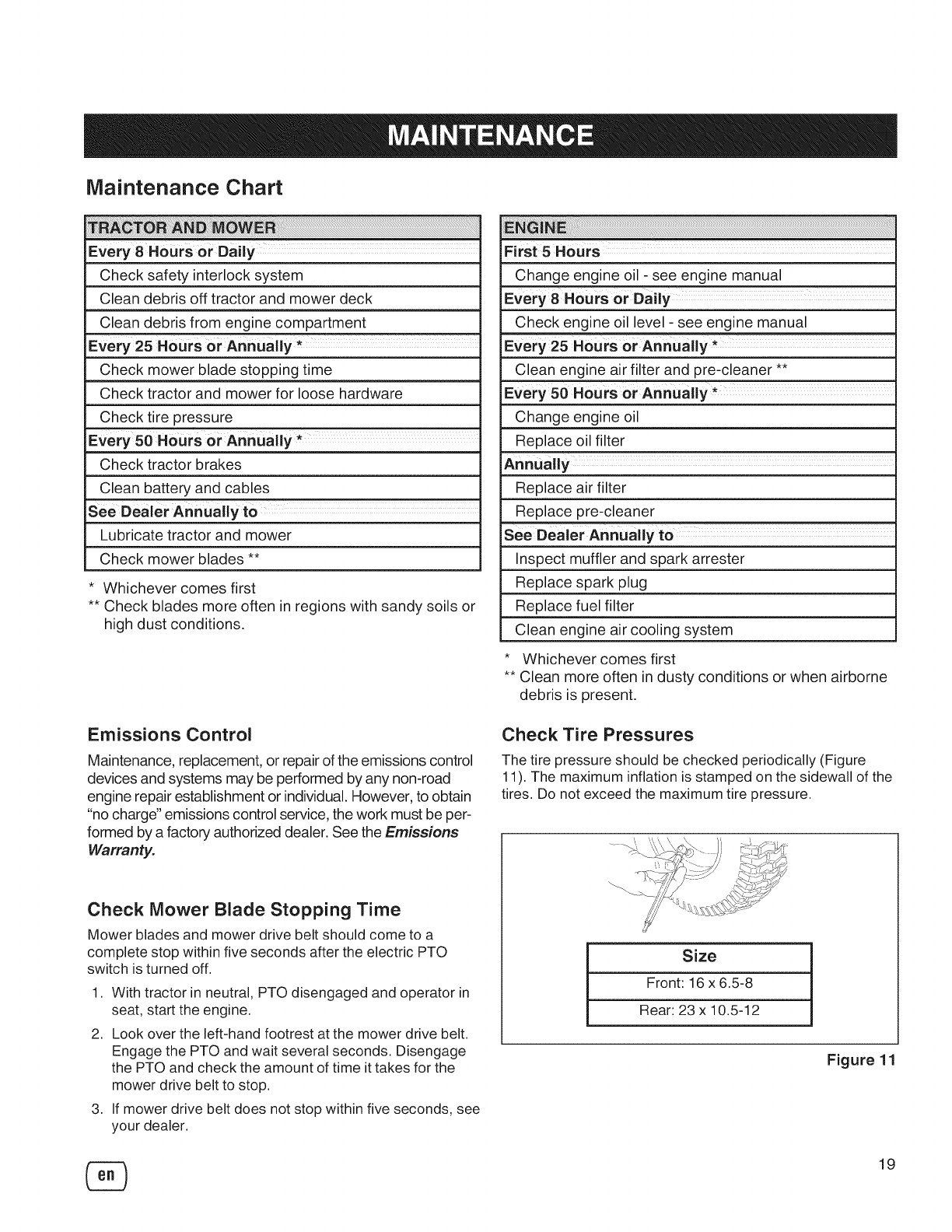
Maintenance Chart
i i i i ti61!i i!i!i!i!i i i!i iiiiiiiii! i!6 i;; !i! i!i!!!iiiiiiii i
Every 8 Hours or Daily
Check safety interlock system
Clean debris off tractor and mower deck
Clean debris from engine compartment
Every 25 Hours or Annually *
Check mower blade stopping time
Check tractor and mower for loose hardware
Check tire pressure
Every 50 Hours or Annually *
Check tractor brakes
Clean battery and cables
See Dealer Annually to
Lubricate tractor and mower
Check mower blades **
* Whichever comes first
** Check blades more often in regions with sandy soils or
high dust conditions.
First 5Hours
Change engine oil - see engine manual
Every 8 Hours or Daily
Check engine oil level - see engine manual
Every 25 Hours or Annually *
Clean engine air filter and pre-cleaner **
Every 50 Hours or Annually*
Change engine oil
Replace oil filter
Replace air filter
Replace pre-cleaner
See Dealer Annually to
Inspect muffler and spark arrester
Replace spark plug
Replace fuel filter
Clean engine air cooling system
* Whichever comes first
** Clean more often in dusty conditions or when airborne
debris is present.
Emissions Control
Maintenance, replacement, or repair of the emissions control
devices and systems may be performed by any non-road
engine repair establishment or individual. However, to obtain
"no charge" emissions control service, the work must be per-
formed by a factory authorized dealer. See the Emissions
Warranty.
Check Mower Blade Stopping Time
Mower blades and mower drive belt should come to a
complete stop within five seconds after the electric PTO
switch is turned off.
1. With tractor in neutral, PTO disengaged and operator in
seat, start the engine.
2. Look over the left-hand footrest at the mower drive belt.
Engage the PTO and wait several seconds. Disengage
the PTO and check the amount of time it takes for the
mower drive belt to stop.
3. If mower drive belt does not stop within five seconds, see
your dealer.
Check Tire Pressures
The tire pressure should be checked periodically (Figure
11). The maximum inflation is stamped on the sidewall of the
tires. Do not exceed the maximum tire pressure.
Size
Front: 16 x 6.5-8
Rear: 23 x 10.5-12
Figure 11
19
Electronic Fuel Management System
The Electronic Fuel Management System monitors engine
temperature, engine speed, and battery voltage to adjust
the choke during engine starting and warm up. There are no
adjustments on the system. If starting or operation problems
occur, contact Sears Service.
NOTICE: Make sure to follow the steps below or the
Electronic Fuel Management System could be damaged.
= Never start the engine if the battery cables are loose.
= Turn the key to the off position before disconnecting,
removing and/or installing the battery.
Never use a battery charger to start the engine.
Never disconnect the battery cables while the engine is
running.
When connecting the battery cables, first connect the
positive (+) cable and then connect the negative (-) cable
to the battery.
When charging the battery, turn the ignition switch to the
off position and disconnect the negative (-) battery cable
from the battery.
= Do not spray water directly on the Electronic Control Unit.
Battery Charging
,A WARNING
Keep open flames and sparks away from the
battery; the gasses coming from it are highly
explosive. Ventilate the battery well during
charging.
A dead battery or one too weak to start the engine may
be the result of a defect in the charging system or other
electrical component. If there is any doubt about the cause
of the problem, see your dealer. If you need to replace the
battery, follow the steps under Cleaning the Battery and
Cables.
To charge the battery, follow the instructions provided by
the battery charger manufacturer as well as all warnings
included in the safety rules sections of this book. Charge
the battery until fully charged. Do not charge at a rate higher
than 10 amps.
Cleaning the Battery and Cables
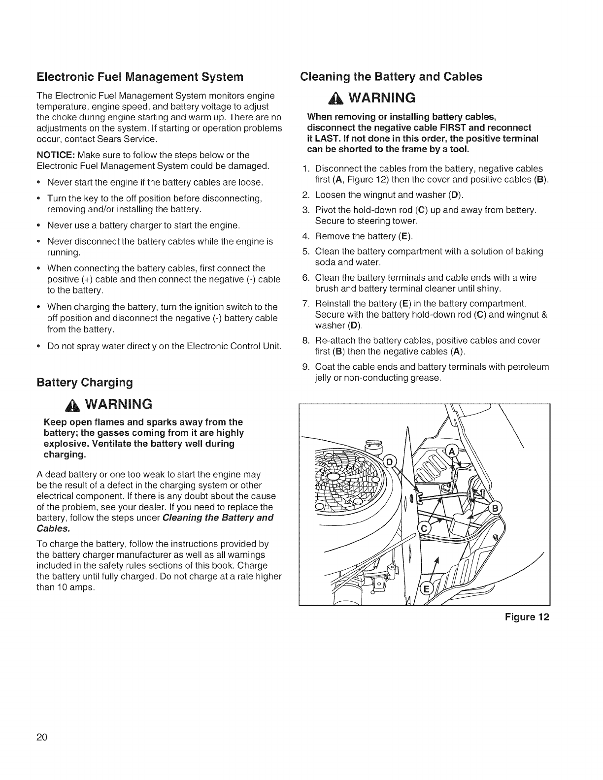
WARNING
When removing or installing battery cables,
disconnect the negative cable FIRST and reconnect
it LAST. if not done in this order, the positive terminal
can be shorted to the frame by a tool.
1,
2.
3.
4.
5.
6.
7.
,
9.
Disconnect the cables from the battery, negative cables
first (A, Figure 12) then the cover and positive cables (B).
Loosen the wingnut and washer (D).
Pivot the hold-down rod (C) up and away from battery.
Secure to steering tower.
Remove the battery (E).
Clean the battery compartment with a solution of baking
soda and water.
Clean the battery terminals and cable ends with a wire
brush and battery terminal cleaner until shiny.
Reinstall the battery (E) in the battery compartment.
Secure with the battery hold-down rod (C) and wingnut &
washer (D).
Re-attach the battery cables, positive cables and cover
first (B) then the negative cables (A).
Coat the cable ends and battery terminals with petroleum
jelly or non-conducting grease.
Figure 12
20
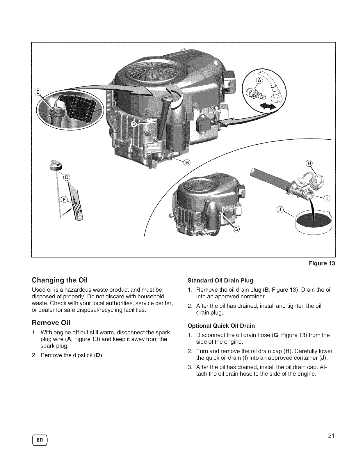
Figure13
Changing the Oil
Used oil is a hazardous waste product and must be
disposed of properly. Do not discard with household
waste. Check with your local authorities, service center,
or dealer for safe disposal/recycling facilities.
Remove Oil
1. With engine off but still warm, disconnect the spark
plug wire (A, Figure 13) and keep it away from the
spark plug.
2. Remove the dipstick (D).
Standard Oil Drain Plug
1. Remove the oil drain plug (B, Figure 13). Drain the oil
into an approved container.
2. After the oil has drained, install and tighten the oil
drain plug.
Optional Quick Oil Drain
1. Disconnect the oil drain hose (G, Figure 13) from the
side of the engine.
2. Turn and remove the oil drain cap (H). Carefully lower
the quick oil drain (I) into an approved container (J).
3. After the oil has drained, install the oil drain cap. At-
tach the oil drain hose to the side of the engine.
21
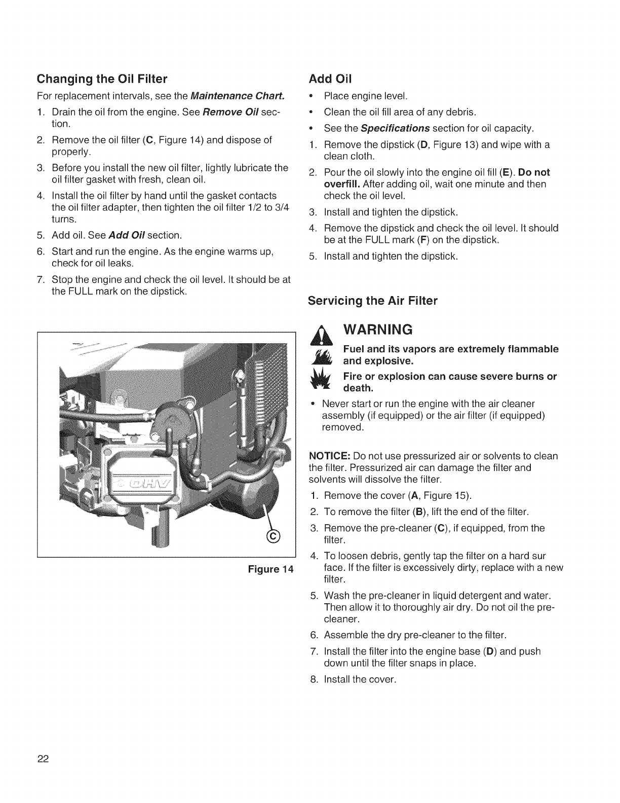
Changing the Oil Filter
For replacement intervals, see the Maintenance Chart.
1. Drain the oil from the engine. See Remove Oil sec-
tion.
2. Remove the oil filter (C, Figure 14) and dispose of
properly.
3. Before you install the new oil filter, lightly lubricate the
oil filter gasket with fresh, clean oil.
4. Install the oil filter by hand until the gasket contacts
the oil filter adapter, then tighten the oil filter 1/2 to 3/4
turns.
5. Add oil. See Add Oil section.
6. Start and run the engine. As the engine warms up,
check for oil leaks.
7. Stop the engine and check the oil level. It should be at
the FULL mark on the dipstick.
Add Oil
• Place engine level.
• Clean the oil fill area of any debris.
° See the Specifications section for oil capacity.
1. Remove the dipstick (D, Figure 13) and wipe with a
clean cloth.
2. Pour the oil slowly into the engine oil fill (E). Do not
overfill. After adding oil, wait one minute and then
check the oil level.
3. Install and tighten the dipstick.
4. Remove the dipstick and check the oil level. It should
be at the FULL mark (F) on the dipstick.
5. Install and tighten the dipstick.
Servicing the Air Filter
WARNING
Fuel and its vapors are extremely flammable
and explosive.
Fire or explosion can cause severe burns or
death.
• Never start or run the engine with the air cleaner
assembly (if equipped) or the air filter (if equipped)
removed.
Figure 14
NOTICE: Do not use pressurized air or solvents to clean
the filter. Pressurized air can damage the filter and
solvents will dissolve the filter.
1. Remove the cover (A, Figure 15).
2. To remove the filter (B), lift the end of the filter.
3. Remove the pre-cleaner (C), if equipped, from the
filter.
4. To loosen debris, gently tap the filter on a hard sur
face. If the filter is excessively dirty, replace with a new
filter.
5. Wash the pre-cleaner in liquid detergent and water.
Then allow it to thoroughly air dry. Do not oil the pre-
cleaner.
6. Assemble the dry pre-cleaner to the filter.
7. Install the filter into the engine base (D) and push
down until the filter snaps in place.
8. Install the cover.
22
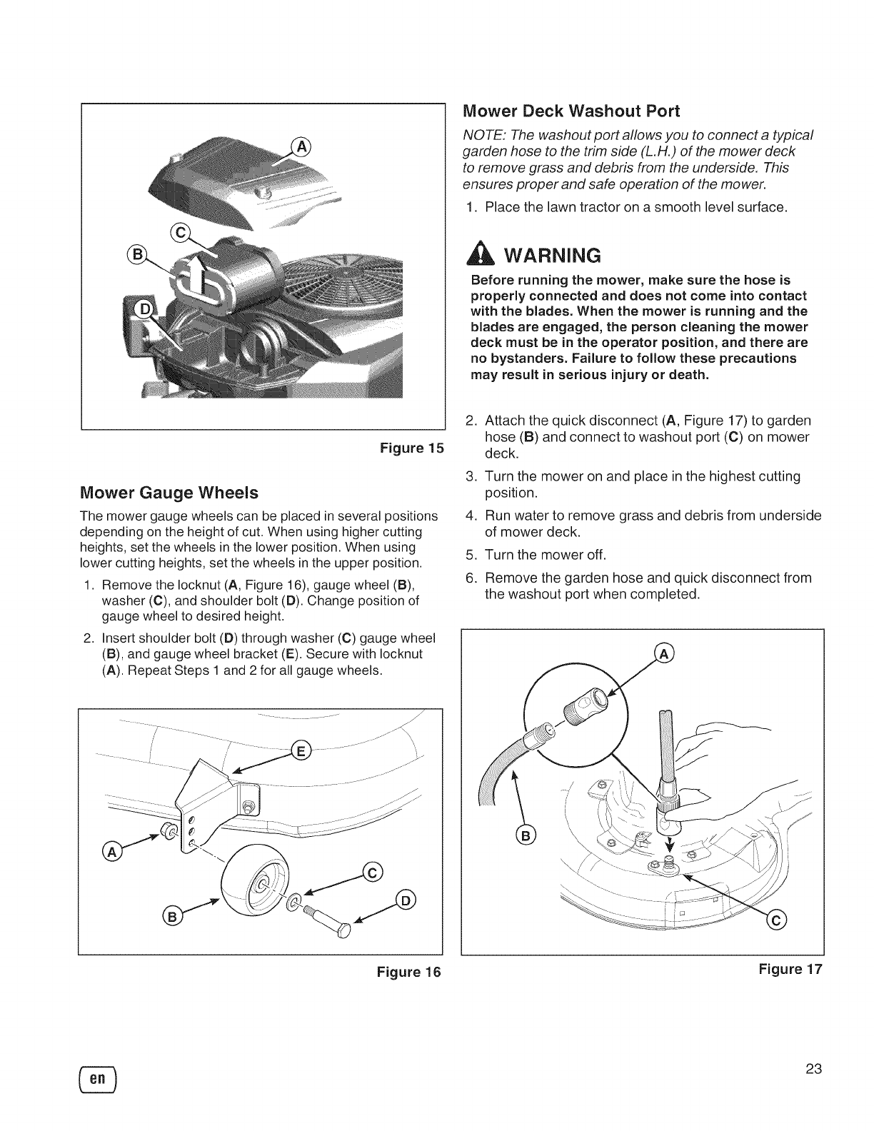
Mower Deck Washout Port
NOTE: The washout port allows you to connect a typical
garden hose to the trim side (L.H.) of the mower deck
to remove grass and debris from the underside. This
ensures proper and safe operation of the mower.
1. Place the lawn tractor on a smooth level surface.
WARNING
Before running the mower, make sure the hose is
properly connected and does not come into contact
with the blades. When the mower is running and the
blades are engaged, the person cleaning the mower
deck must be in the operator position, and there are
no bystanders. Failure to follow these precautions
may result in serious injury or death.
Figure 15
Mower Gauge Wheels
The mower gauge wheels can be placed in several positions
depending on the height of cut. When using higher cutting
heights, set the wheels inthe lower position. When using
lower cutting heights, set the wheels in the upper position.
1. Remove the Iocknut (A, Figure 16), gauge wheel (B),
washer (C), and shoulder bolt (D). Change position of
gauge wheel to desired height.
2. Insert shoulder bolt (D) through washer (C) gauge wheel
(B), and gauge wheel bracket (E). Secure with Iocknut
(A). Repeat Steps 1 and 2 for all gauge wheels.
.
.
4.
5.
6.
Attach the quick disconnect (A, Figure 17) to garden
hose (B) and connect to washout port (C) on mower
deck.
Turn the mower on and place in the highest cutting
position.
Run water to remove grass and debris from underside
of mower deck.
Turn the mower off.
Remove the garden hose and quick disconnect from
the washout port when completed.
Figure 16 Figure 17
23
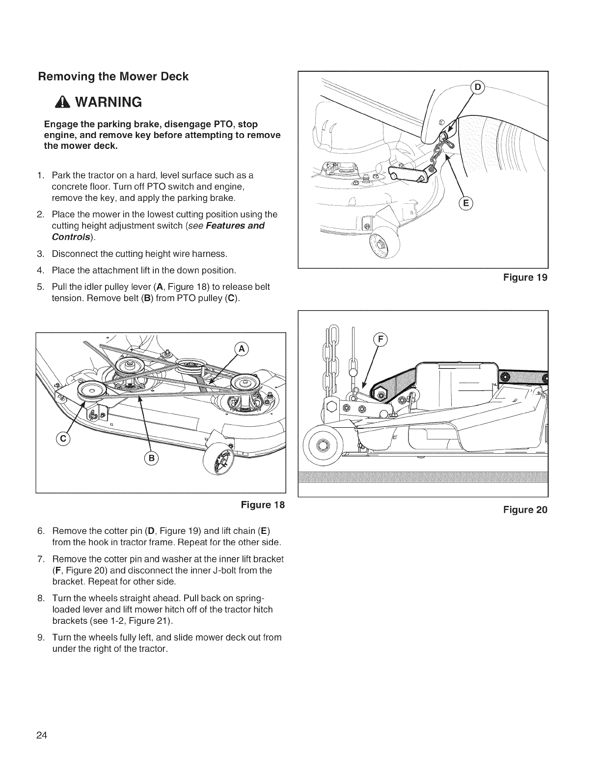
Removing the Mower Deck
WARNING
Engage the parking brake, disengage PTO, stop
engine, and remove key before attempting to remove
the mower deck.
1,
2,
3,
4.
5.
Park the tractor on a hard, level surface such as a
concrete floor. Turn off PTO switch and engine,
remove the key, and apply the parking brake.
Place the mower in the lowest cutting position using the
cutting height adjustment switch (see Features and
Controls).
Disconnect the cutting height wire harness.
Place the attachment lift in the down position.
Pull the idler pulley lever (A, Figure 18) to release belt
tension. Remove belt (B) from PTO pulley (C).
Figure lg
?
6,
7,
,
g,
Figure 18
Remove the cotter pin (D, Figure 19) and lift chain (E)
from the hook in tractor frame. Repeat for the other side.
Remove the cotter pin and washer at the inner lift bracket
(F, Figure 20) and disconnect the inner J-bolt from the
bracket. Repeat for other side.
Turn the wheels straight ahead. Pull back on spring-
loaded lever and lift mower hitch off of the tractor hitch
brackets (see 1-2, Figure 21 ).
Turn the wheels fully left, and slide mower deck out from
under the right of the tractor.
Figure 20
24
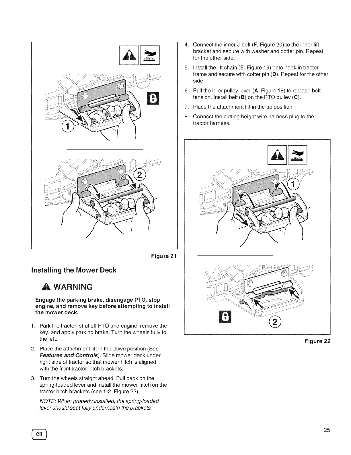
Figure21
Installing the Mower Deck
WARNING
Engage the parking brake, disengage PTO, stop
engine, and remove key before attempting to install
the mower deck.
1,
2,
3,
Park the tractor, shut off PTO and engine, remove the
key, and apply parking brake. Turn the wheels fully to
the left.
Place the attachment lift in the down position (See
Features and Controls). Slide mower deck under
right side of tractor so that mower hitch is aligned
with the front tractor hitch brackets.
Turn the wheels straight ahead. Pull back on the
spring-loaded lever and install the mower hitch on the
tractor hitch brackets (see 1-2, Figure 22).
NOTE: When properly installed, the spring-loaded
lever should seat fully underneath the brackets.
4,
5,
Connect the inner J-bolt (F, Figure 20) to the inner lift
bracket and secure with washer and cotter pin. Repeat
for the other side.
Install the lift chain (E, Figure 19) onto hook in tractor
frame and secure with cotter pin (D). Repeat for the other
side.
6. Pull the idler pulley lever (A, Figure 18) to release belt
tension. Install belt (B) on the PTO pulley (C).
7. Place the attachment lift in the up position.
8. Connect the cutting height wire harness plug to the
tractor harness.
®
Figure 22
®25
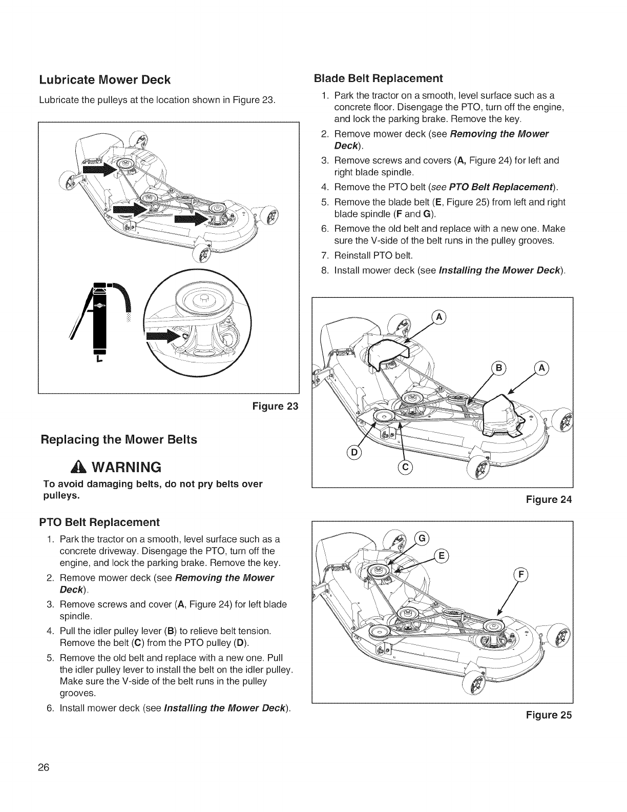
Lubricate Mower Deck
Lubricate the pulleys at the location shown in Figure 23.
m
L
Figure 23
Replacing the Mower Belts
WARNING
To avoid damaging belts, do not pry belts over
pulleys.
PTO Belt Replacement
1. Park the tractor on a smooth, level surface such as a
concrete driveway. Disengage the PTO, turn off the
engine, and lock the parking brake. Remove the key.
2. Remove mower deck (see Removing the Mower
Deck).
3. Remove screws and cover (A, Figure 24) for left blade
spindle.
4. Pull the idler pulley lever (B) to relieve belt tension.
Remove the belt (C) from the PTO pulley (D).
5. Remove the old belt and replace with a new one. Pull
the idler pulley lever to install the belt on the idler pulley.
Make sure the V-side of the belt runs in the pulley
grooves.
6. Install mower deck (see Installing the Mower Deck).
Blade Belt Replacement
1. Park the tractor on a smooth, level surface such as a
concrete floor. Disengage the PTO, turn off the engine,
and lock the parking brake. Remove the key.
2. Remove mower deck (see Removing the Mower
Deck).
3. Remove screws and covers (A, Figure 24) for left and
right blade spindle.
4. Remove the PTO belt (see PTO Belt Replacement).
5. Remove the blade belt (E, Figure 25) from left and right
blade spindle (F and G).
6. Remove the old belt and replace with a new one. Make
sure the V-side of the belt runs in the pulley grooves.
7. Reinstall PTO belt.
8. Install mower deck (see Installing the Mower Deck).
Figure 24
Figure 25
26
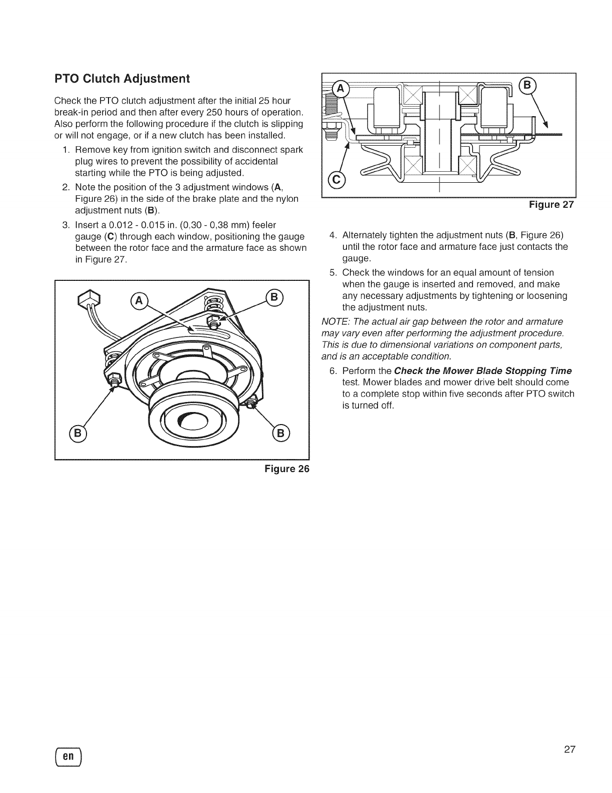
PTO Clutch Adjustment
Check the PTO clutch adjustment after the initial 25 hour
break-in period and then after every 250 hours of operation.
Also perform the following procedure if the clutch is slipping
or will not engage, or if a new clutch has been installed.
1. Remove key from ignition switch and disconnect spark
plug wires to prevent the possibility of accidental
starting while the PTO is being adjusted.
2. Note the position of the 3 adjustment windows (A,
Figure 26) in the side of the brake plate and the nylon
adjustment nuts (B).
3. Insert a 0.012 - 0.015 in. (0,30 - 0,38 mm) feeler
gauge (C) through each window, positioning the gauge
between the rotor face and the armature face as shown
in Figure 27.
®
Figure 27
4. Alternately tighten the adjustment nuts (B, Figure 26)
until the rotor face and armature face just contacts the
gauge.
5. Check the windows for an equal amount of tension
when the gauge is inserted and removed, and make
any necessary adjustments by tightening or loosening
the adjustment nuts.
NOTE: The actual air gap between the rotor and armature
may vary even after performing the adjustment procedure.
This is due to dimensional variations on component parts,
and is an acceptable condition.
6. Perform the Check the Mower Blade Stopping Time
test. Mower blades and mower drive belt should come
to a complete stop within five seconds after PTO switch
is turned off.
Figure 26
27
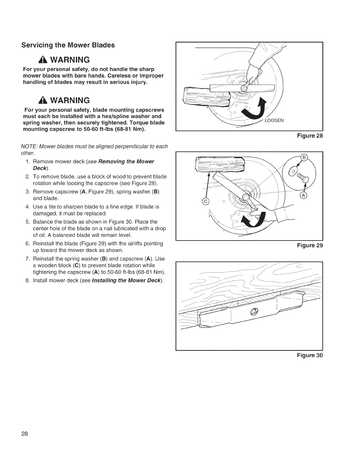
Servicing the Mower Blades
WARNING
For your personal safety, do not handle the sharp
mower blades with bare hands. Careless or improper
handling of blades may result in serious injury.
WARNING
For your personal safety, blade mounting capscrews
must each be installed with ahex/spline washer and
spring washer, then securely tightened. Torque blade
mounting capscrew to 50-60 ft-lbs (68-81 Nm).
NOTE: Mower blades must be aligned perpendicular to each
other.
1. Remove mower deck (see Removing the Mower
Deck).
2. To remove blade, use a block of wood to prevent blade
rotation while loosing the capscrew (see Figure 28).
3. Remove capscrew (A, Figure 29), spring washer (B)
and blade.
4. Use a file to sharpen blade to a fine edge. If blade is
damaged, it must be replaced.
5. Balance the blade as shown in Figure 30. Place the
center hole of the blade on a nail lubricated with a drop
of oil. A balanced blade will remain level.
6. Reinstall the blade (Figure 29) with the airlifts pointing
up toward the mower deck as shown.
7. Reinstall the spring washer (B) and capscrew (A). Use
a wooden block (C) to prevent blade rotation while
tightening the capscrew (A) to 50-60 ft-lbs (68-81 Nm).
8. Install mower deck (see Installing the Mower Deck).
LOOSEN
Figure 28
Figure 29
Figure 30
28
Storage
WARNING
Never store the unit (with fuel) in an
enclosed, poorly ventilated structure. Fuel
vapors can travel to an ignition source (such
as a furnace, water heater, etc.) and cause an
explosion. Fuel vapor is also toxic to humans
and animals.
When Storing Fuel Or Equipment With Fuel In Tank
° Store away from furnaces, stoves, water heaters or
other appliances that have pilot lights or other ignition
sources because they can ignite fuel vapors.
Equipment
Disengage the PTO, set the parking brake, and remove
the key.
Battery life will be increased if it is removed. Put in a cool,
dry place and fully charged about once a month. If the
battery is left in the unit, disconnect the negative cable.
Fuel System
Fuel can become stale when stored over 30 days. Stale
fuel causes acid and gum deposits to form in the fuel sys-
tem or on essential carburetor parts. To keep fuel fresh,
use fuel stabilizer.
There is no need to drain gasoline from the engine if a
fuel stabilizer is added according to instructions. Run the
engine for 2 minutes to circulate the stabilizer throughout
the fuel system before storage.
Engine Oil
While the engine is still warm, change the engine oil.
Before starting the unit after it has been stored:
•Check all fluid levels. Check all maintenance items.
•Perform all recommended checks and procedures
found in this manual.
•Allow the engine to warm up for several minutes
before use.
29

Troubleshooting the Tractor
PROBLEM LOOK FOR REMEDY
Brake pedal not i Fully depress brake pedal.
depressed.
PTO (electric clutch) switch Place in OFF position.
is in ON position.
Cruise control engaged. Move knob to NEUTRAL/OFF position.
Out of fuel. i lf engine is hot, allow it to cool, then refill the fuel tank.
Fuse is blown, i Replace fuse or contact Sears Service.
Battery terminals require See Cleaning the Battery and Cables section.
cleaning.
Engine will not turnover
or start. Battery discharged or i Recharge or replace battery. Use Die Hard Gold #50785.
dead.
Wiring loose or broken, iVisually check wiring. If wires are frayed or broken, see
authorized dealer.
Solenoid or starter motor Contact Sears Service.
faulty.
Safety interlock switch Contact Sears Service.
faulty.
Water in fuel. Contact Sears Service.
Gas is old or stale. Contact Sears Service.
Fuel mixture too rich. Clean air filter.
Engine starts hard or
runs poorly. Engine has other problem. Contact Sears Service.
Low oil level. Check/add oil as required.
Engine knocks. Using wrong grade oil. See Oil Recommendations Chart.
Engine running too hot. Contact Sears Service.
Excessive oil Using wrong grade oil. See Oil Recommendations Chart.
iconsumption. Too much oil in Drain excess oil.
crankcase.
Engine exhaust is black. Dirty air filter. See Servicing the Air Filter section.
Ground speed control i Depress pedals.
pedals not depressed.
Transmission release lever Move into DRIVE position.
Engine runs, but tractor in PUSH position.
will not drive. Parking brake is engaged, i Disengage parking brake.
Traction drive belt is Contact Sears Service.
broken or slipping.
30

Troubleshooting the Tractor (Continued)
PROBLEM LOOK FOR REMEDY
Brake will not hold. Internal brake worn. Contact Sears Service.
Steering linkage is loose. Contact Sears Service.
Tractor steers hard or Improper tire inflation. See Check Tire Pressure section.
handles poorly. Front wheel spindle Contact Sears Service.
bearings dry.
Troubleshooting the Mower
PROBLEM LOOK FOR REMEDY
i Lift linkage not properly Contact Sears Service.
Mower will not raise, attached or damaged.
Mower not leveled Level the mower. See Setup Instructions.
properly.
Mower cut is uneven, i Tractor tires not properly See Check Tire Pressure section.
i inflated.
i Engine speed too slow. Set to full throttle.
Mower cut is rough Ground speed too fast. Slow down.
looking. Mower has other problem. Contact Sears Service.
i Engine speed too slow. Set to full throttle.
Ground speed to fast. Slow down.
i Dirty or clogged air filter. See Servicing the Air Filter section.
Engine stalls easily with i Cutting height set too low. Cut tall grass at maximum cutting height during first pass.
mower engaged, i Engine not up to operating Run engine for several minutes to warm-up.
itemperature.
i Starting mower in tall Start the mower in a cleared area.
grass.
Excessive mower i Mower has other problem. Contact Sears Service.
vibration.
PTO not engaged. Engage the PTO.
Engine runs and tractor
drives, but mower will Mower has other problem. Contact Sears Service.
not drive.
31
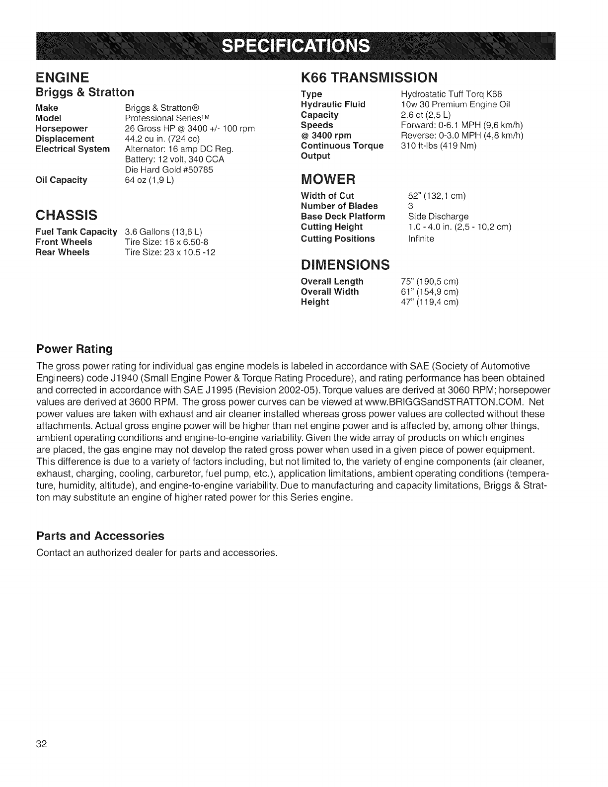
ENGINE
Briggs & Stratton Type
Make Briggs & Stratton® Hydraulic Fluid
Model Professional SeriesTM Capacity
Horsepower 26 Gross HP @3400 +/- 100 rpm Speeds
Displacement 442 cu in. (724 cc) @3400 rpm
Electrical System Alternator: 16 amp DC Reg. Continuous Torque
Battery: 12 volt, 340 CCA Output
Die Hard Gold #50785
64 oz (1,9 L)Oil Capacity
CHASSIS
Fuel Tank Capacity 3.6 Gallons (13,6 L)
Front Wheels Tire Size: 16x 6.50-8
Rear Wheels Tire Size: 23 x 10.5 -12
K66 TRANSMISSION
Hydrostatic Tuff Torq K66
10w 30 Premium Engine Oil
2.6 qt (2,5 L)
Forward: 0-6.1 MPH (9,6 km/h)
Reverse: 0-3.0 MPH (4,8 km/h)
310 ft-lbs (419 Nm)
MOWER
Width of Cut
Number of Blades
Base Deck Platform
Cutting Height
Cutting Positions
52" (132,1 cm)
3
Side Discharge
1.0- 4.0 in. (2,5- 10,2 cm)
Infinite
DiMENSiONS
Overall Length
Overall Width
Height
75" (190,5 cm)
61" (154,9 cm)
47" (119,4 cm)
Power Rating
The gross power rating for individual gas engine models is labeled in accordance with SAE (Society of Automotive
Engineers) code J1940 (Small Engine Power & Torque Rating Procedure), and rating performance has been obtained
and corrected in accordance with SAE J1995 (Revision 2002-05). Torque values are derived at 3060 RPM; horsepower
values are derived at 3600 RPM. The gross power curves can be viewed at www.BRIGGSandSTRATTON.COM. Net
power values are taken with exhaust and air cleaner installed whereas gross power values are collected without these
attachments. Actual gross engine power will be higher than net engine power and is affected by, among other things,
ambient operating conditions and engine-to-engine variability. Given the wide array of products on which engines
are placed, the gas engine may not develop the rated gross power when used in a given piece of power equipment.
This difference is due to a variety of factors including, but not limited to, the variety of engine components (air cleaner,
exhaust, charging, cooling, carburetor, fuel pump, etc.), application limitations, ambient operating conditions (tempera-
ture, humidity, altitude), and engine-to-engine variability. Due to manufacturing and capacity limitations, Briggs & Strat-
ton may substitute an engine of higher rated power for this Series engine.
Parts and Accessories
Contact an authorized dealer for parts and accessories.
32

CRAFTSMAN FULL WARRANTY
FOR THREE YEARS from the date of purchase, all non-expendable parts of this riding equipment are war-
ranted against any defects in material or workmanship. A defective non-expendable part will receive free
in-home repair or replacement if repair is impossible.
FOR FIVE YEARS from the date of purchase, the frame and front axle of this riding equipment are warranted
against any defects in material or workmanship. A defective frame or front axle will receive free in-home re-
pair or replacement if repair is impossible.
FOR 90 DAYS from the date of purchase, the battery (an expendable part) of this riding equipment is war-
ranted against any defects in material or workmanship (our testing proves that it will not hold a charge). A
defective battery will receive free in-home replacement.
ADDITIONAL LIFETIME LIMITED WARRANTY on CAST IRON FRONT AXLE (if equipped)
FOR AS LONG AS IT IS USED by the original owner after the fifth year from the date of purchase, the cast
iron front axle (if equipped) of this riding equipment is warranted against any defects in material or workman-
ship. With proof of purchase, a defective cast iron front axle will receive free in-home replacement.
WARRANTY SERVICE
For warranty coverage details to obtain free repair or replacement, call 1-800-659-5917 or visit the web site:
www.craftsman.com.
In all cases above, if part repair or replacement is impossible, the riding equipment will be replaced free of
charge with the same or an equivalent model.
All of the above warranty coverage is void if this riding equipment is ever used while providing commercial
services or if rented to another person.
This warranty covers ONLY defects in material and workmanship. Warranty coverage does NOT include:
o
o
Expendable parts (except battery) that can wear out from normal use within the warranty period, includ-
ing but not limited to blades, spark plugs, air cleaners, belts, and oil filters.
Standard maintenance servicing, oil changes, or tune-ups.
Tire replacement or repair caused by punctures from outside objects, such as nails, thorns, stumps, or
glass.
Tire or wheel replacement or repair resulting from normal wear, accident, or improper operation or main-
tenance.
Repairs necessary because of operator abuse, including but not limited to damage caused by towing
objects beyond the capability of the riding equipment, impacting objects that bend the frame, axle as-
sembly or crankshaft, or over-speeding the engine.
Repairs necessary because of operator negligence, including but not limited to, electrical and mechani-
cal damage caused by improper storage, failure to use the proper grade and amount of engine oil, failure
to keep the deck clear of flammable debris, or failure to maintain the riding equipment according to the
instructions contained in the operator's manual.
• Engine (fuel system) cleaning or repairs caused by fuel determined to be contaminated or oxidized
(stale). In general, fuel should be used within 30 days of its purchase date.
Normal deterioration and wear of the exterior finishes, or product label replacement.
This warranty gives you specific legal rights, and you may also have other rights which vary from state to
state.
Sears Brands Management Corporation, Hoffman Estates, IL 60179
33

Congratulations on making a smart purchase.
Your new Craftsman@ product is designed and
manufactured for years of dependable operation. But like
all products, it may require repair from time to time. That's
when having a Repair Protection Agreement can save
you money and aggravation.
Here's what the Repair Protection Agreement*
includes:
[] Expert service by our 10,000 professional repair
specialists
[] Unlimited service and no charge for parts and
labor on all covered repairs
[] Product replacement up to $1500 if your covered
product can't be fixed
[] Discount of 10% from regular price of service and
related installed parts not covered by the agreement;
also, 10% off regular price of preventive maintenance
check
[] Fast help by phone - we call it Rapid Resolution -
phone support from a Sears representative. Think of
us as a "talking owner's manual."
Once you purchase the Repair Protection Agreement, a
simple phone call is all that it takes for you to schedule
service.You can call anytime day or night, or schedule a
service appointment online.
The Repair Protection Agreement is a risk-free purchase.
If you cancel for any reason during the product warranty
period, we will provide a full refund. Or, a prorated
refund anytime after the product warranty period expires.
Purchase your Repair Protection Agreement today!
Some limitations and exclusions apply. For prices
and additional information in the U.S.A. call 1-800-
827=6655.
*Coverage in Canada varies on some items. For full
details call Sears Canada at 1-800-361-6665.
Sears installation Service
For Sears professional installation of home appliances,
garage door openers, water heaters, and other major
home items, in the U.S.A. or Canada call 1-800-4-MY-
HOME@.
34

35

Your Home
For troubleshooting, product manuals and expert advice:
managemylife
www.managemylife.com
For repair - in your home - of all major brand appliances,
lawn and garden equipment, or heating and cooling systems,
no matter who made it, no matter who sold it!
For the replacement parts, accessories and
owner's manuals that you need to do-it-yourself.
For Sears professional installation of home appliances
and items like garage door openers and water heaters.
1-800-4-MY-HOME ®(1-800-469-4663)
Call anytime, day or night (U.S.A. and Canada)
www.sears.com www.sears.ca
Our Home
For repair of carry-in items like vacuums, lawn equipment,
and electronics, call anytime for the location of your nearest
Sears Parts & Repair Service Center
1-800-488-1222 (U.S.A.) 1-800-469-4663 (Canada)
www.sears.com www.sears.ca
To purchase a protection agreement on a product serviced by Sears:
1-800-827-6655 (U.S.A.) 1-800-361-6665 (Canada)
Para pedir servicio de reparaci6n
a domicilio, y para ordenar piezas:
1-888-SU-HOGAR ®
(1-888-784-6427)
Au Canada pour service en fran£ais:
1-800-LE-FOYER Mc
(1-800-533-6937)
www.sears.ca
www.sears.com
® Registered Trademark /TMTrademark of KCD IP, LLC in the United States, or Sears Brands, LLC in other countries
® Marca Registrada /TMMarca de Fabrica de KCD IP, LLC en Estados Unidos, o Sears Brands, LLC in otros paises
MCMarque de commerce /MDMarque d6pos6e de Sears Brands, LLC

PTS - I
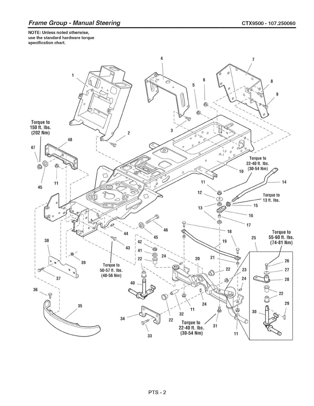
Frame Group -Manual Steering CTX9500 =107.250060
NOTE: UnJess noted otherwise,
use the standard hardware torque
specification chart.
34
33
11
32
11
12
13
31
1;4
11
PTS - 2
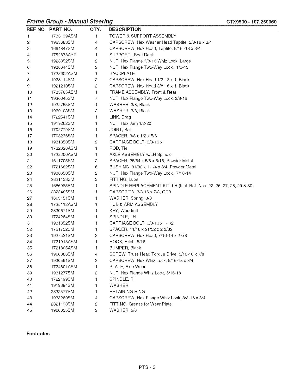
Frame Group -Manual Steering
REF NO
1
2
3
4
5
6
7
8
9
10
11
12
13
14
15
16
17
18
19
20
21
22
23
24
25
26
27
28
29
3O
31
32
33
34
35
36
37
38
39
4O
41
42
43
44
45
CTX9500 - 107.250060
PART NO.
1733139ASM
1923683SM
1664847SM
1752878AYP
1928352SM
1930644SM
1722602ASM
1923114SM
1921210SM
1733765ASM
1930645SM
1922755SM
1960103SM
1722541SM
1919262SM
1702779SM
1708236SM
1931350SM
1722626ASM
1722200ASM
1611705SM
1721682SM
1930650SM
2821133SM
1686985SM
2823485SM
1663151SM
1725112ASM
2830671SM
1724264SM
1931352SM
1721752SM
1927531SM
1721918ASM
1721805ASM
1960086SM
1930591SM
1724801ASM
1931277SM
1722199SM
1919394SM
2832577SM
1933260SM
2821133SM
1960035SM
QTY.
1
4
4
1
2
2
1
2
2
1
7
1
2
1
1
1
1
2
1
1
2
6
2
3
1
1
1
1
1
1
1
1
2
1
1
4
2
1
2
1
1
1
4
2
2
DESCRiPTiON
TOWER & SUPPORT ASSEMBLY
CAPSCREW, Hex Washer Head Taptite, 3/8-16 x 3/4
CAPSCREW, Hex Head, Taptite, 5/16 -18 x 3/4
SUPPORT, Seat Deck
NUT, Hex Flange 3/8-16 Whiz Lock, Large
NUT, Hex Flange Two-Way Lock, 1/2-13
BACKPLATE
CAPSCREW, Hex Head 1/2-13 x 1, Black
CAPSCREW, Hex Head 3/8-16 x 1, Black
FRAME ASSEMBLY, Front & Rear
NUT, Hex Flange Two-Way Lock, 3/8-16
WASHER, 3/8, Black
WASHER, 3/8, Black
LINK, Drag
NUT, Hex Jam 1/2-20
JOINT, Ball
SPACER, 3/8 x 1/2 x 5/8
CARRIAGE BOLT, 3/8-16 x 1
ROD, Tie
AXLE ASSEMBLY w/LH Spindle
SPACER, 25/64 x 5/8 x 5/16, Powder Metal
BUSHING, 31/32 x 1-1/4 x 3/4, Powder Metal
NUT, Hex Flange Two-Way Lock, 7/16-14
FITTING, Lube
SPINDLE REPLACEMENT KIT, LH (Incl. Ref. Nos. 22, 26, 27, 28, 29 & 30)
CAPSCREW, 3/8-16 x 7/8, GR8
WASHER, Spring, 3/8
HUB & ARM ASSEMBLY
KEY, Woodruff
SPINDLE, LH
CARRIAGE BOLT, 3/8-16 x 1-1/2
SPACER, 11/16 x 21/32 x 2 3/32
CAPSCREW, Hex Head, 7/16-14 x 2 G8
HOOK, Hitch, 5/16
BUMPER, Black
SCREW, Truss Head Torque Drive, 5/16-18 x 7/8
CAPSCREW, Hex Whiz Lock, 5/16-18 x 3/4
PLATE, Axle Wear
NUT, Hex Flange Whiz Lock, 5/16-18
SPINDLE, RH
WASHER
RETAINING RING
CAPSCREW, Hex Flange Whiz Lock, 3/8-16 x 3/4
FITTING, Grease for Wear Plate
WASHER, 5/8
Footnotes
PTS - 3

Frame Group -Manual Steering CTX9500 =107.250060
NOTE: UnJess noted otherwise,
use the standard hardware torque
specification chart.
34
33
11
32
11
12
13
31
1;4
11
PTS - 4

Frame Group -Manual Steering
REF NO PART NO. QTY. DESCRiPTiON
46 2860645SM 1 CAPSCREW, Hex Head, 5/8-11 × 3-1/2
47 2860646SM 1 NUT, He× Flange Two-Way Lock, 5/8-11
48 1722212ASM 1 PLATE, Axle
CTX9500 =107.250060
Footnotes
PTS - 5
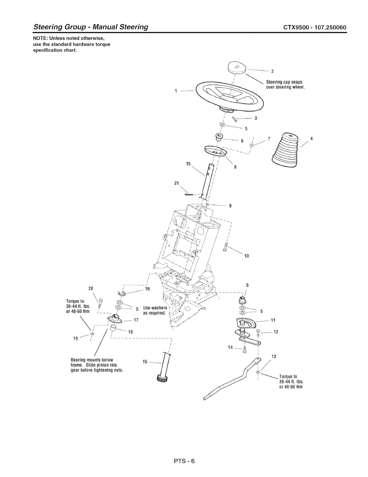
Steering Group -Manual Steering CTX9500- 107.250060
NOTE: Unless noted otherwise,
use the standard hardware torque
specification chart.
2
Stee_ag cap snaps
ovat sIasd_ w_ea_
....... 5
2:1
20 _ .......15
Bearing mounts baI_w
_rame. 81l_eptn[oaiata
gea_be_o_e_[_h_eef_9r_s.
15
Torqu8to
3;5-_ It IbS.
or 48-50 Nm
PTS - 6
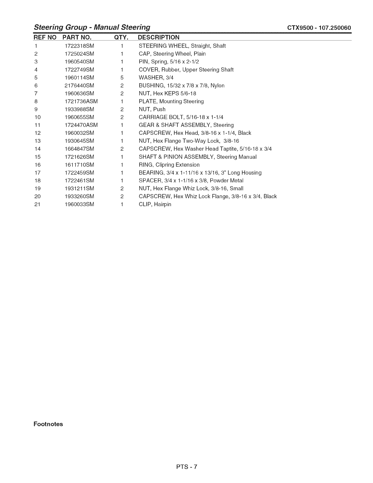
Steering Group -Manual Steering
REF NO
1
2
3
4
5
6
7
8
9
10
11
12
13
14
15
16
17
18
19
20
21
CTX9500 - 107.250060
PART NO.
1722318SM
1725024SM
1960540SM
1722749SM
1960114SM
2176440SM
1960636SM
1721736ASM
1933988SM
1960655SM
1724470ASM
1960032SM
1930645SM
1664847SM
1721626SM
1611710SM
1722459SM
1722461SM
1931211SM
1933260SM
1960033SM
QTY.
1
1
1
1
5
2
2
1
2
2
1
1
1
2
1
1
1
1
2
2
1
DESCRiPTiON
STEERING WHEEL, Straight, Shaft
CAP, Steering Wheel, Plain
PIN, Spring, 5/16 x 2-1/2
COVER, Rubber, Upper Steering Shaft
WASHER, 3/4
BUSHING, 15/32 x 7/8 x 7/8, Nylon
NUT, Hex KEPS 5/6-18
PLATE, Mounting Steering
NUT, Push
CARRIAGE BOLT, 5/16-18 x 1-1/4
GEAR & SHAFT ASSEMBLY, Steering
CAPSCREW, Hex Head, 3/8-16 x 1-1/4, Black
NUT, Hex Flange Two-Way Lock, 3/8-16
CAPSCREW, Hex Washer Head Taptite, 5/16-18 x 3/4
SHAFT & PINION ASSEMBLY, Steering Manual
RING, Clipring Extension
BEARING, 3/4 x 1-11/16 x 13/16, 3" Long Housing
SPACER, 3/4 x 1-1/16 x 3/8, Powder Metal
NUT, Hex Flange Whiz Lock, 3/8-16, Small
CAPSCREW, Hex Whiz Lock Flange, 3/8-16 x 3/4, Black
CLIP, Hairpin
Footnotes
PTS - 7
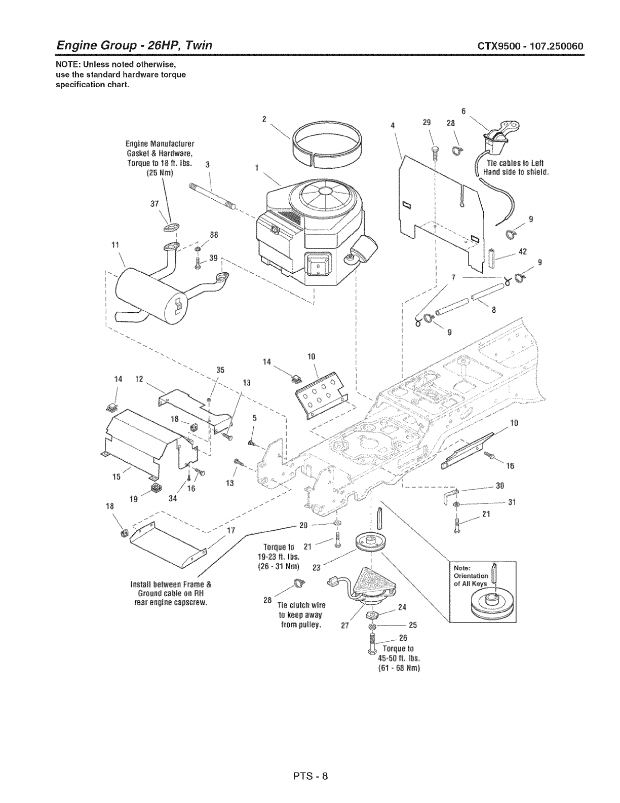
Engine Group -26HP, Twin CTX9500 =107.250060
NOTE: Unless noted otherwise,
use the standard hardware torque
specification chart.
En_iae Ma_u_a_u_at
Oaske_& Har_wa_
To_que_o18 if, _bs_
(25Nm_
1l
14 12 35
10
14
29 28
42
9
15
i_StS# betwee_ Frame &
G_oa_d¢ab_e#a RH
rea_e#g_necapscrew 28 Tie C_u_#_wire
_akeep _way
1_[ampulley,
PTS - 8
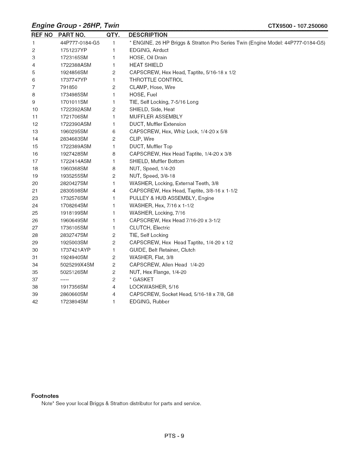
Engine Group -26HP, Twin
REF NO PART NO. QTY.
1 44P777-0184-G5 1
2 1751237YP 1
3 1723165SM 1
4 1722388ASM 1
5 1924856SM 2
6 1737747YP 1
7 791850 2
8 1734985SM 1
9 1701011SM 1
10 1722392ASM 2
11 1721706SM 1
12 1722390ASM 1
13 1960295SM 6
14 2834683SM 2
15 1722389ASM 1
16 1927428SM 8
17 1722414ASM 1
18 1960368SM 8
19 1935255SM 2
20 2820427SM 1
21 2830598SM 4
23 1732576SM 1
24 1708264SM 1
25 1918199SM 1
26 1960649SM 1
27 1736105SM 1
28 2832747SM 2
29 1925003SM 2
30 1737421AYP 1
31 1924940SM 2
34 5025299X4SM 2
35 5025126SM 2
37 ..... 2
38 1917356SM 4
39 2860660SM 4
42 1723894SM 1
CTX9500 - 107.250060
DESCRiPTiON
* ENGINE, 26 HP Briggs & Stratton Pro Series Twin (Engine Model: 44P777-0184-G5)
EDGING, Airduct
HOSE, Oil Drain
HEAT SHIELD
CAPSCREW, Hex Head, Taptite, 5/16-18 x 1/2
THROTTLE CONTROL
CLAMP, Hose, Wire
HOSE, Fuel
TIE, Self Locking, 7-5/16 Long
SHIELD, Side, Heat
MUFFLER ASSEMBLY
DUCT, Muffler Extension
CAPSCREW, Hex, Whiz Lock, 1/4-20 x 5/8
CLIP, Wire
DUCT, Muffler Top
CAPSCREW, Hex Head Taptite, 1/4-20 x 3/8
SHIELD, Muffler Bottom
NUT, Speed, 1/4-20
NUT, Speed, 3/8-18
WASHER, Locking, External Teeth, 3/8
CAPSCREW, Hex Head, Taptite, 3/8-16 x 1-1/2
PULLEY & HUB ASSEMBLY, Engine
WASHER, Hex, 7/16 x 1-1/2
WASHER, Locking, 7/16
CAPSCREW, Hex Head 7/16-20 x 3-1/2
CLUTCH, Electric
TIE, Self Locking
CAPSCREW, Hex Head Taptite, 1/4-20 x 1/2
GUIDE, Belt Retainer, Clutch
WASHER, Flat, 3/8
CAPSCREW, Allen Head 1/4-20
NUT, Hex Flange, 1/4-20
*GASKET
LOCKWASHER, 5/16
CAPSCREW, Socket Head, 5/16-18 x 7/8, G8
EDGING, Rubber
Footnotes
Note* See your local Briggs & Stratton distributor for parts and service.
PTS - 9
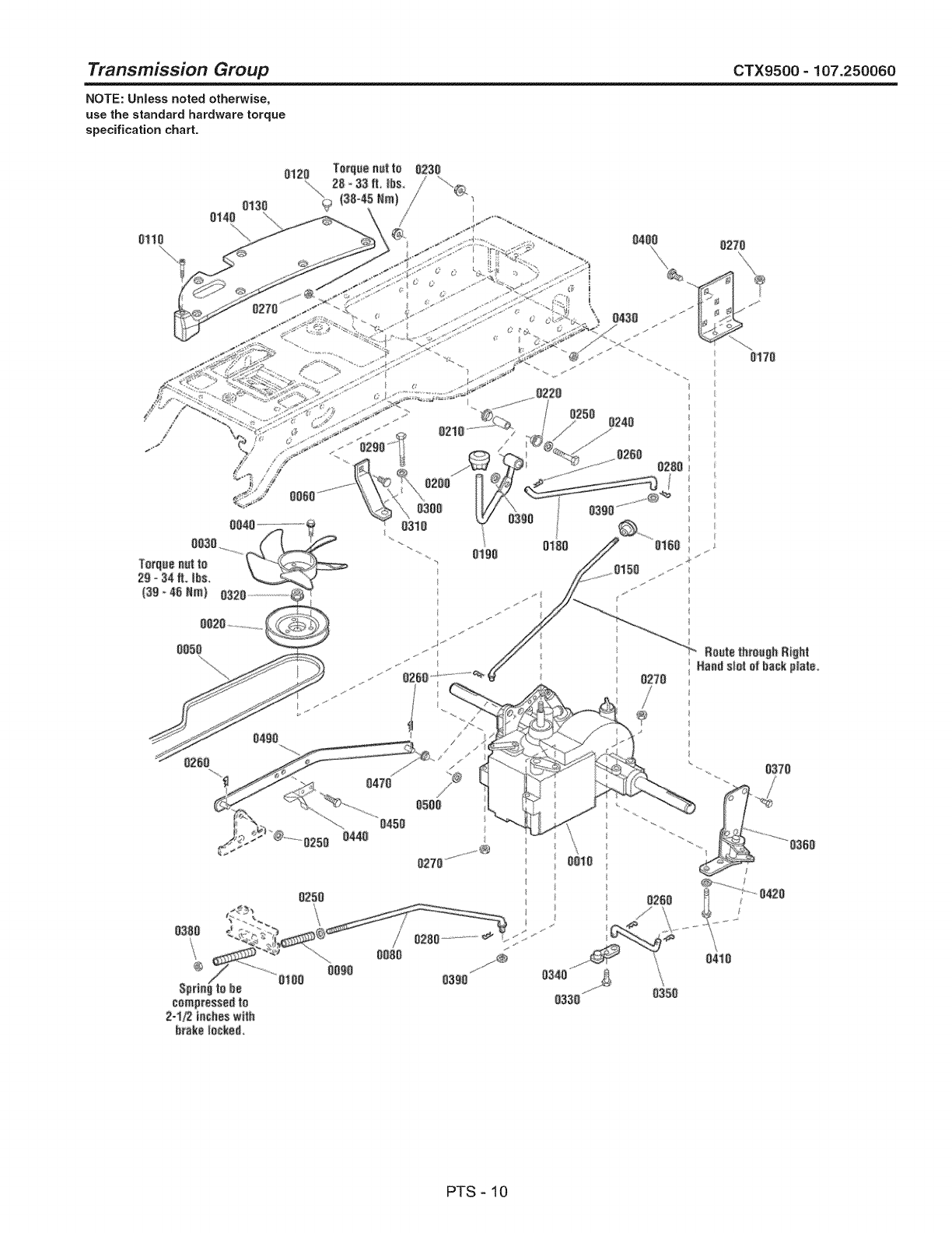
Transmission Group CTX9500 =107.250060
NOTE: UnJess noted otherwise,
use the standard hardware torque
specification chart.
\
®
0100
_z
B0ute_h _i_ht
0370
PTS - 10
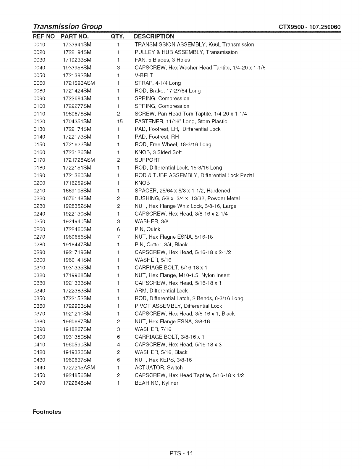
Transmission Group CTX9500- 107.250060
REF NO PART NO.
0010 1733941SM
0020 1722194SM
0030 1719233SM
0040 1933958SM
0050 1721392SM
0060 1721593ASM
0080 1721424SM
0090 1722684SM
0100 1729277SM
0110 1960676SM
0120 1704351SM
0130 1722174SM
0140 1722173SM
0150 1721622SM
0160 1723126SM
0170 1721728ASM
0180 1722151SM
0190 1721360SM
0200 1716289SM
0210 1669105SM
0220 1676148SM
0230 1928352SM
0240 1922130SM
0250 1924940SM
0260 1722460SM
0270 1960686SM
0280 1918447SM
0290 1921719SM
0300 1960141SM
0310 1931335SM
0320 1719968SM
0330 1921333SM
0340 1722383SM
0350 1722152SM
0360 1722903SM
0370 1921210SM
0380 1960687SM
0390 1918267SM
0400 1931350SM
0410 1960590SM
0420 1919326SM
0430 1960637SM
0440 1727215ASM
0450 1924856SM
0470 1722648SM
QTY.
1
1
1
3
1
1
1
1
1
2
15
1
1
1
1
2
1
1
1
1
2
2
1
3
6
7
1
1
1
1
1
1
1
1
1
1
2
3
6
4
2
6
1
2
1
DESCRiPTiON
TRANSMISSION ASSEMBLY, K66L Transmission
PULLEY & HUB ASSEMBLY, Transmission
FAN, 5 Blades, 3 Holes
CAPSCREW, Hex Washer Head Taptite, 1/4-20 x 1-1/8
V-BELT
STRAP, 4-1/4 Long
ROD, Brake, 17-27/64 Long
SPRING, Compression
SPRING, Compression
SCREW, Pan Head Tor× Taptite, 1/4-20 x 1-1/4
FASTENER, 11/16" Long, Stem Plastic
PAD, Footrest, LH, Differential Lock
PAD, Footrest, RH
ROD, Free Wheel, 18-3/16 Long
KNOB, 3 Sided Soft
SUPPORT
ROD, Differential Lock, 15-3/16 Long
ROD & TUBE ASSEMBLY, Differential Lock Pedal
KNOB
SPACER, 25/64 x 5/8 x 1-1/2, Hardened
BUSHING, 5/8 × 3/4 x 13/32, Powder Metal
NUT, Hex Flange Whiz Lock, 3/8-16, Large
CAPSCREW, Hex Head, 3/8-16 x 2-1/4
WASHER, 3/8
PIN, Quick
NUT, Hex Flagne ESNA, 5/16-18
PiN, Cotter, 3/4, Black
CAPSCREW, Hex Head, 5/16-18 x 2-1/2
WASHER, 5/16
CARRIAGE BOLT, 5/16-18 x1
NUT, Hex Flange, M10-1.5, Nylon insert
CAPSCREW, Hex Head, 5/16-18 x 1
ARM, Differential Lock
ROD, Differential Latch, 2 Bends, 6-3/16 Long
PIVOT ASSEMBLY, Differential Lock
CAPSCREW, Hex Head, 3/8-16 x 1, Black
NUT, Hex Flange ESNA, 3/8-16
WASHER, 7/16
CARRIAGE BOLT, 3/8-16 x1
CAPSCREW, Hex Head, 5/16-18 x 3
WASHER, 5/16, Black
NUT, Hex KEPS, 3/8-16
ACTUATOR, Switch
CAPSCREW, He× Head Taptite, 5/16-18 x 1/2
BEARING, Nyliner
Footnotes
PTS - 11

Transmission Group CTX9500 =107.250060
NOTE: UnJess noted otherwise,
use the standard hardware torque
specification chart.
\
®
0100
_z
B0ute_h _i_ht
0370
PTS - 12

Transmission Group
REF NO PART NO. QTY.
0490 1726757SM 1
0500 1960027SM 1
DESCRiPTiON
ARM & WELD PINS ASSEMBLY, Control K66
WASHER, Flat, 1/2
CTX9500 - 107.250060
Footnotes
PTS - 13
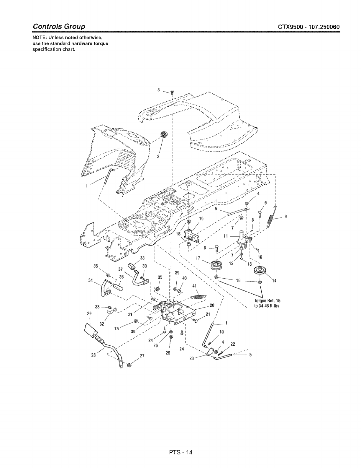
Controls Group CTX9500 =107.250060
NOTE: Unless noted otherwise,
use the standard hardware torque
specification chart.
34
24
23
_:#34*45|H_s
PTS - 14
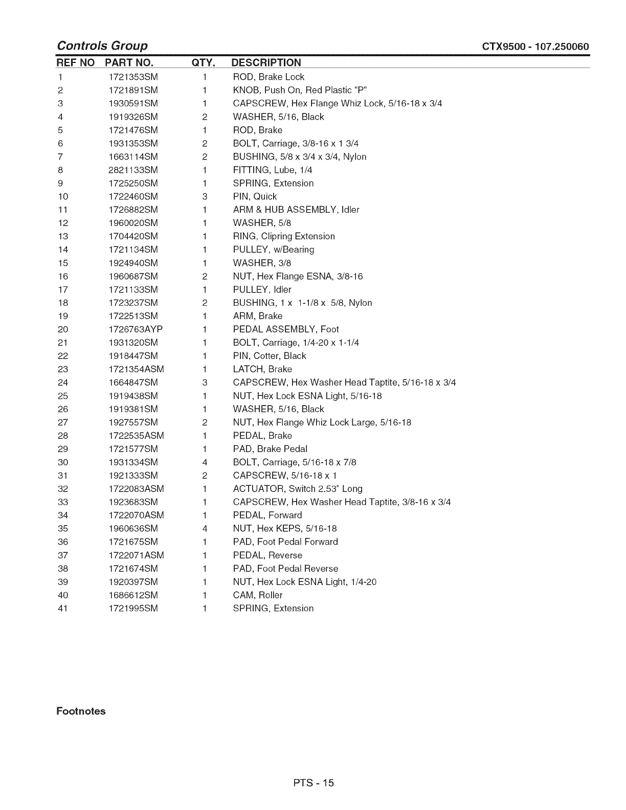
Controls Group CTX9500 =107.250060
REF NO PART NO.
1 1721353SM
2 1721891SM
3 1930591SM
4 1919326SM
5 1721476SM
6 1931353SM
7 1663114SM
8 2821133SM
9 1725250SM
10 1722460SM
11 1726882SM
12 1960020SM
13 1704420SM
14 1721134SM
15 1924940SM
16 1960687SM
17 1721133SM
18 1723237SM
19 1722513SM
20 1726763AYP
21 1931320SM
22 1918447SM
23 1721354ASM
24 1664847SM
25 1919438SM
26 1919381SM
27 1927557SM
28 1722535ASM
29 1721577SM
30 1931334SM
31 1921333SM
32 1722083ASM
33 1923683SM
34 1722070ASM
35 1960636SM
36 1721675SM
37 1722071ASM
38 1721674SM
39 1920397SM
40 1686612SM
41 1721995SM
QTY.
1
1
1
2
1
2
2
1
1
3
1
1
1
1
1
2
1
2
1
1
1
1
1
3
1
1
2
1
1
4
2
1
1
1
4
1
1
1
1
1
1
DESCRIPTION
ROD, Brake Lock
KNOB, Push On, Red Plastic "P"
CAPSCREW, Hex Flange Whiz Lock, 5/16-18 x 3/4
WASHER, 5/16, Black
ROD, Brake
BOLT, Carriage, 3/8-16 x 1 3/4
BUSHING, 5/8 x 3/4 x 3/4, Nylon
FITTING, Lube, 1/4
SPRING, Extension
PiN, Quick
ARM & HUB ASSEMBLY, Idler
WASHER, 5/8
RING, Clipring Extension
PULLEY, w/Bearing
WASHER, 3/8
NUT, Hex Flange ESNA, 3/8-16
PULLEY, Idler
BUSHING, 1 x 1-1/8 x 5/8, Nylon
ARM, Brake
PEDAL ASSEMBLY, Foot
BOLT, Carriage, 1/4-20 x 1-1/4
PIN, Cotter, Black
LATCH, Brake
CAPSCREW, Hex Washer Head Taptite, 5/16-18 x 3/4
NUT, Hex Lock ESNA Light, 5/16-18
WASHER, 5/16, Black
NUT, Hex Flange Whiz Lock Large, 5/16-18
PEDAL, Brake
PAD, Brake Pedal
BOLT, Carriage, 5/16-18 x 7/8
CAPSCREW, 5/16-18 x 1
ACTUATOR, Switch 2.53" Long
CAPSCREW, Hex Washer Head Taptite, 3/8-16 x 3/4
PEDAL, Forward
NUT, Hex KEPS, 5/16-18
PAD, Foot Pedal Forward
PEDAL, Reverse
PAD, Foot Pedal Reverse
NUT, Hex Lock ESNA Light, 1/4-20
CAM, Roller
SPRING, Extension
Footnotes
PTS - 15
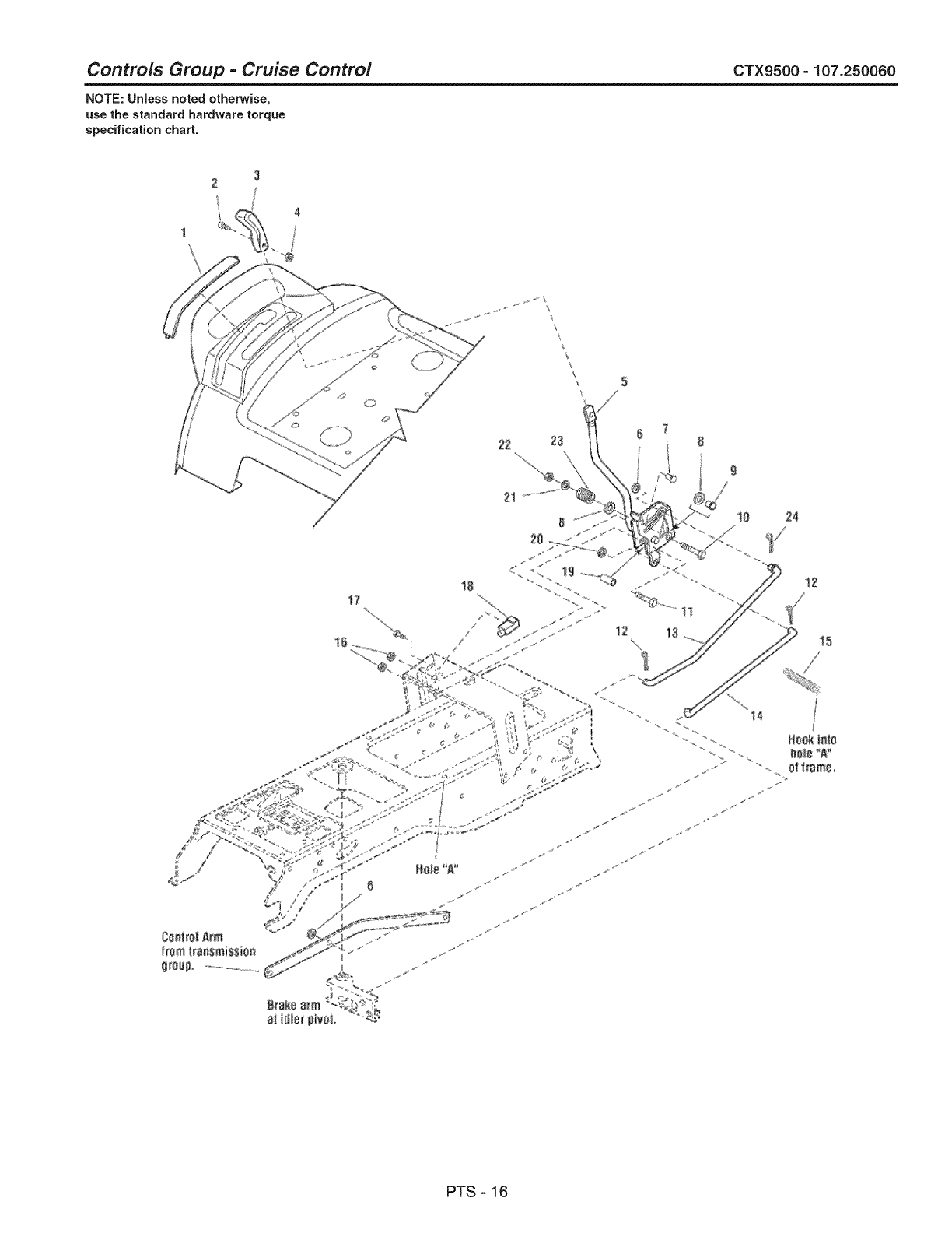
Controls Group -Cruise Control CTX9500- 107.250060
NOTE: Unless noted otherwise,
use the standard hardware torque
specification chart.
3
2
I 4
1
\\
\
\
\
\
17 18
12
12
15
ControlAim
f[om transmission
g_oup ..............................
PTS - 16
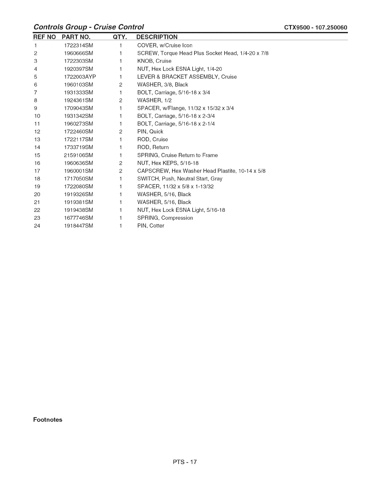
Controls Group -Cruise Control
REF NO
1
2
3
4
5
6
7
8
9
10
11
12
13
14
15
16
17
18
19
20
21
22
23
24
CTX9500 - 107.250060
PART NO.
1722314SM
1960666SM
1722303SM
1920397SM
1722003AYP
1960103SM
1931333SM
1924361SM
1709043SM
1931342SM
1960273SM
1722460SM
1722117SM
1733719SM
2159106SM
1960636SM
1960001SM
1717050SM
1722080SM
1919326SM
1919381SM
1919438SM
1677746SM
1918447SM
QTY.
1
1
1
1
1
2
1
2
1
1
1
2
1
1
1
2
2
1
1
1
1
1
1
1
DESCRiPTiON
COVER, w/Cruise Icon
SCREW, Torque Head Plus Socket Head, 1/4-20 x 7/8
KNOB, Cruise
NUT, Hex Lock ESNA Light, 1/4-20
LEVER & BRACKET ASSEMBLY, Cruise
WASHER, 3/8, Black
BOLT, Carriage, 5/16-18 x 3/4
WASHER, 1/2
SPACER, w/Flange, 11/32 x 15/32 x 3/4
BOLT, Carriage, 5/16-18 x 2-3/4
BOLT, Carriage, 5/16-18 x 2-1/4
PiN, Quick
ROD, Cruise
ROD, Return
SPRING, Cruise Return to Frame
NUT, Hex KEPS, 5/16-18
CAPSCREW, Hex Washer Head Plastite, 10-14 x 5/8
SWITCH, Push, Neutral Start, Gray
SPACER, 11/32 x 5/8 x 1-13/32
WASHER, 5/16, Black
WASHER, 5/16, Black
NUT, Hex Lock ESNA Light, 5/16-18
SPRING, Compression
PIN, Cotter
Footnotes
PTS - 17

Electrical Group CTX9500 =107.250060
NOTE: UnJess noted otherwise,
use the standard hardware torque
specification chart.
HOOD MOUNTED DASH MOUNTED
7
15
PTS - 18

Electrical Group CTX9500 =107.250060
REF NO PART NO.
1 1721810SM
2 1677371SM
3 1723451SM
4 1722669SM
5 5022180SM
6 1726556SM
7 1727185SM
8 1925003SM
9 1665238SM
10 1665237SM
12 1725074SM
13 1724865SM
14 2860750SM
15 2820426SM
16 1728963SM
17 1686734SM
18 1717163SM
19 1717550SM
20 1717549SM
21 1960547SM
22 2101025SM
23 1701011SM
24 1716951SM
25 1713535SM
26 1721830SM
27 1603618SM
28 1677296SM
29 2816622SM
30 2816964SM
31 2821319SM
32 2823341SM
33 1713163SM
34 1685215SM
35 1722009SM
36 1927428SM
37 1726810ASM
38 1704379SM
39 1732006SM
40 1717050SM
41 2860665SM
42 1917365SM
43 1722309SM
44 1686921SM
45 1685303SM
46 1960536SM
QTY.
1
4
4
1
1
1
1
4
1
1
1
1
2
3
1
1
1
1
1
1
1
4
1
1
1
1
1
3
2
2
2
1
1
1
2
1
1
1
1
5
5
1
1
1
2
DESCRiPTiON
HEADLIGHT ASSEMBLY, 4 Bulb (Includes Ref. Nos. 2 & 3)
BULB, Headlight, 12.8V
SOCKET ASSEMBLY, Headlight, Sealed
HARNESS, Headlight
SWITCH, PTO Push/Pull Symbols
SWITCH, RMO Module Only
KEY, RMO Module, Plastic
CAPSCREW, Hex Washer Head Taptite, 1/4-20 x 1/2, Black
BREAKER, Circuit, 12 Volt 20 Amps
WIRE, 12GA 5-15/16 Long, Red
PANEL, Instrument w/Fuel Gage & Hour Meter (Includes Ref. No. 13)
COVER, Instrument Panel
NUT, KEPS Lock 5/16-24 (CE/Export) (Used only on RMO/ACS Models)
LOCKWASHER, External Tooth, 5/16
SOLENOID (CE/Export) (Used only on RMO/ACS Models)
SWITCH ASSEMBLY, Ignition, 6 Pin INDAK (Includes Ref. Nos. 18, 19, 20, 21 & 22)
KEYS, Set of 2
COVER, For Ignition Switch, Plastic
NUT, Hex Flange, 5/8-32, Ignition Switch
LOCKWASHER, Internal Tooth, 5/8, Thin
WASHER, Shim
TIE, Strap, 7-5/16 Long (CE/Export) (Used only on RMO/ACS Models)
SWITCH, Headlights, 2 Terminal
BOOT, Insulator Cable Terminal, 1-15/16 Long, Red
CABLE, #6 x 25" Long, Ring Terminals
CABLE, #6 x 8" Long, Ring Terminals
BOOT, Insulator Battery Terminal
NUT, Hex, 1/4-20
LOCKWASHER, 1/4
WASHER, 1/4
CAPSCREW, Hex Head, 1/4-20 x 3/4
CABLE, #6 x 26 Long, Ring Terminal
BATTERY, 12 Volt
STRAP, Battery, 14 Long, Rubber
CAPSCREW, Hex Head Taptite, 1/4-20 x 3/8
BRACKET, Switch Mount
SWITCH, Reverse Pedal (CE/Export) (Used only on RMO/ACS Models)
SWITCH, Push Button, Foot Pedal
SWITCH, Cruise Control, Grey, NO
SCREW, Pan Head Torx, #10-32 x 1/2
LOCKWASHER, 3/16 #10
PLUG, Hole 3", Round
SENDER, Fuel Tank (Includes Ref. 45)
GASKET
CAPSCREW, Hex Washer Head Plastite, 1/4 x 1/2
Footnotes
PTS - 19

Electrical Group CTX9500 =107.250060
NOTE: UnJess noted otherwise,
use the standard hardware torque
specification chart.
............................................................................................................................................................ ii <.................................................................................................................................................................................................... '
HOOD MOUNTED DASH MOUNTED
8
6
5
10
UNDER HOOD I
I
k48
Tiemainharness 23 I
andstarterwire '_ im
up_Wiresshoo_d \_ ¢_
nethangbelow -
sidepanelwith
hoodclosed,
To Eiestrlc
Clutch
To Charge Cirsait
ToFeeJ
SheFOff ToOil
Pressure
Sensor
Torquescrewsto 25_30in. Ibs,(2.8 _&3 Hm)
Useabalancedtorque sequencetoensure
propersealbetweenfuelsenderandfueltank_
UNDER SEAT DECK
(Nc)
47
jf
50 46 23 45
ToEngine
Magneto
21
22
0NOER .......
FRAME
Switch
4.3
,z ,_-' ®Reverse
;36 Pedal
Switch
19
20 18 16
i5
23 24
Tie solenoid
wires to
Switch
Tieupper !
haNess
totower, *
i:
I
I
UNDER HOOD
32
33 31 30 29
26
28
27
ToEngine
Ground
35
34
PTS - 18
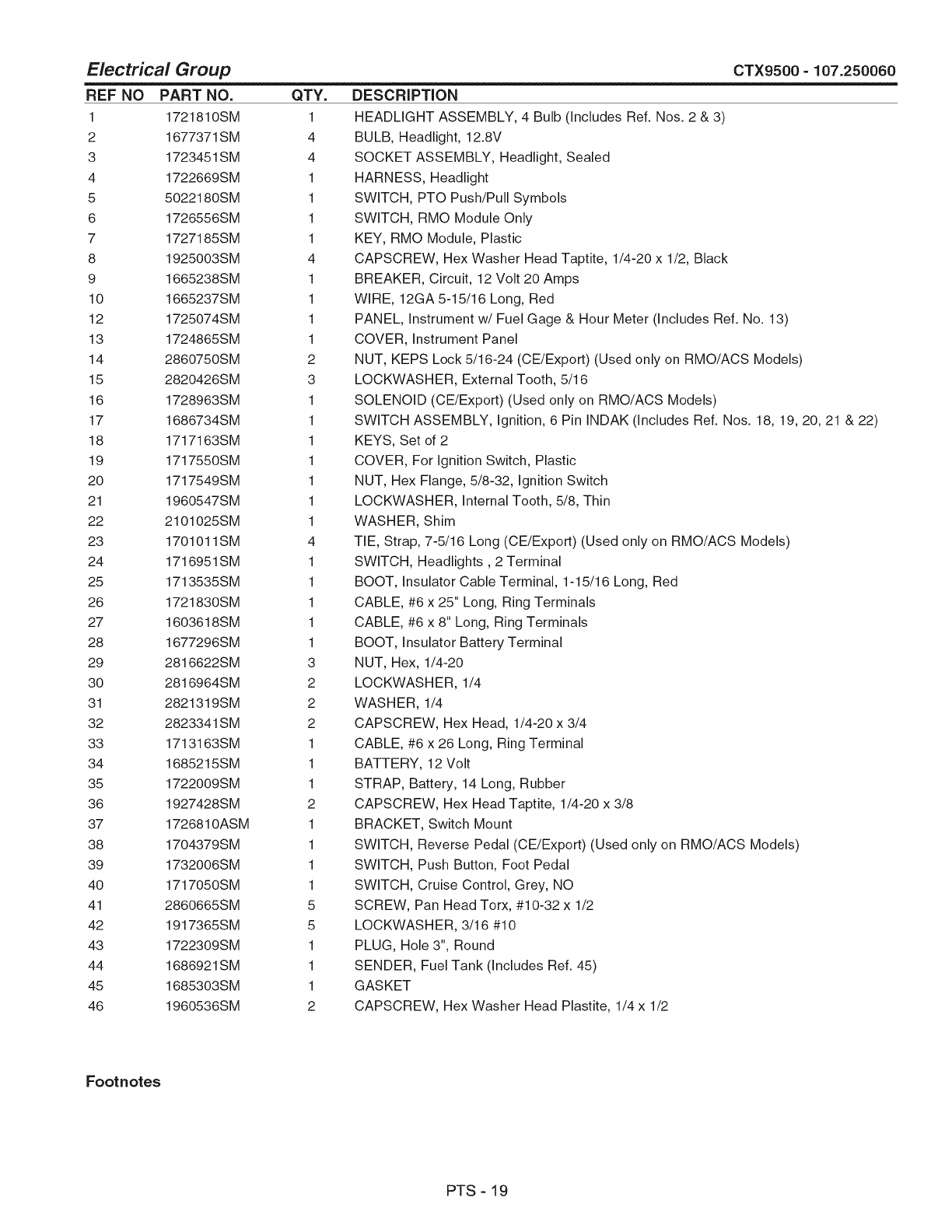
Electrical Group CTX9500 =107.250060
REF NO PART NO.
1 1721810SM
2 1677371SM
3 1723451SM
4 1722669SM
5 5022180SM
6 1726556SM
7 1727185SM
8 1925003SM
9 1665238SM
10 1665237SM
12 1725074SM
13 1724865SM
14 2860750SM
15 2820426SM
16 1728963SM
17 1686734SM
18 1717163SM
19 1717550SM
20 1717549SM
21 1960547SM
22 2101025SM
23 1701011SM
24 1716951SM
25 1713535SM
26 1721830SM
27 1603618SM
28 1677296SM
29 2816622SM
30 2816964SM
31 2821319SM
32 2823341SM
33 1713163SM
34 1685215SM
35 1722009SM
36 1927428SM
37 1726810ASM
38 1704379SM
39 1732006SM
40 1717050SM
41 2860665SM
42 1917365SM
43 1722309SM
44 1686921SM
45 1685303SM
46 1960536SM
QTY.
1
4
4
1
1
1
1
4
1
1
1
1
2
3
1
1
1
1
1
1
1
4
1
1
1
1
1
3
2
2
2
1
1
1
2
1
1
1
1
5
5
1
1
1
2
DESCRiPTiON
HEADLIGHT ASSEMBLY, 4 Bulb (Includes Ref. Nos. 2 & 3)
BULB, Headlight, 12.8V
SOCKET ASSEMBLY, Headlight, Sealed
HARNESS, Headlight
SWITCH, PTO Push/Pull Symbols
SWITCH, RMO Module Only
KEY, RMO Module, Plastic
CAPSCREW, Hex Washer Head Taptite, 1/4-20 x 1/2, Black
BREAKER, Circuit, 12 Volt 20 Amps
WIRE, 12GA 5-15/16 Long, Red
PANEL, Instrument w/Fuel Gage & Hour Meter (Includes Ref. No. 13)
COVER, Instrument Panel
NUT, KEPS Lock 5/16-24 (CE/Export) (Used only on RMO/ACS Models)
LOCKWASHER, External Tooth, 5/16
SOLENOID (CE/Export) (Used only on RMO/ACS Models)
SWITCH ASSEMBLY, Ignition, 6 Pin INDAK (Includes Ref. Nos. 18, 19, 20, 21 & 22)
KEYS, Set of 2
COVER, For Ignition Switch, Plastic
NUT, Hex Flange, 5/8-32, Ignition Switch
LOCKWASHER, Internal Tooth, 5/8, Thin
WASHER, Shim
TIE, Strap, 7-5/16 Long (CE/Export) (Used only on RMO/ACS Models)
SWITCH, Headlights, 2 Terminal
BOOT, Insulator Cable Terminal, 1-15/16 Long, Red
CABLE, #6 x 25" Long, Ring Terminals
CABLE, #6 x 8" Long, Ring Terminals
BOOT, Insulator Battery Terminal
NUT, Hex, 1/4-20
LOCKWASHER, 1/4
WASHER, 1/4
CAPSCREW, Hex Head, 1/4-20 x 3/4
CABLE, #6 x 26 Long, Ring Terminal
BATTERY, 12 Volt
STRAP, Battery, 14 Long, Rubber
CAPSCREW, Hex Head Taptite, 1/4-20 x 3/8
BRACKET, Switch Mount
SWITCH, Reverse Pedal (CE/Export) (Used only on RMO/ACS Models)
SWITCH, Push Button, Foot Pedal
SWITCH, Cruise Control, Grey, NO
SCREW, Pan Head Torx, #10-32 x 1/2
LOCKWASHER, 3/16 #10
PLUG, Hole 3", Round
SENDER, Fuel Tank (Includes Ref. 45)
GASKET
CAPSCREW, Hex Washer Head Plastite, 1/4 x 1/2
Footnotes
PTS - 19
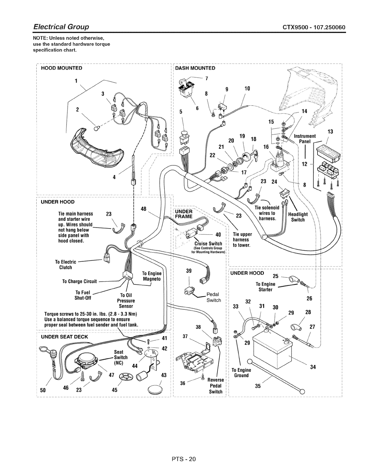
Electrical Group CTX9500 =107.250060
NOTE: UnJess noted otherwise,
use the standard hardware torque
specification chart.
............................................................................................................................................................ ii <.................................................................................................................................................................................................... '
HOOD MOUNTED DASH MOUNTED
8
6
5
10
UNDER HOOD I
I
k48
Tiemainharness 23 I
andstarterwire '_ im
up_Wiresshoo_d \_ ¢_
nethangbelow -
sidepanelwith
hoodclosed,
To Eiestrlc
Clutch
To Charge Cirsait
ToFeeJ
SheFOff ToOil
Pressure
Sensor
Torquescrewsto 25_30in. Ibs,(2.8 _&3 Hm)
Useabalancedtorque sequencetoensure
propersealbetweenfuelsenderandfueltank_
UNDER SEAT DECK
(Nc)
47
jf
50 46 23 45
ToEngine
Magneto
21
22
0NOER .......
FRAME
Switch
4.3
,z ,_-' ®Reverse
;36 Pedal
Switch
19
20 18 16
i5
23 24
Tie solenoid
wires to
Switch
Tieupper !
haNess
totower, *
i:
I
I
UNDER HOOD
32
33 31 30 29
26
28
27
ToEngine
Ground
35
34
PTS - 20

Electrical Group
REF NO PART NO.
47 1718981SM
48 1739708YP
50 1725302SM
51 1716329SM
QTY.
1
1
1
1
CTX9500 = 107.250060
DESCRiPTiON
SWITCH, Seat, Grey, NC (CE/E×port) (Used only on RMO/ACS Models)
HARNESS, Wiring (CE/Export) (Used only on RMO/ACS Models)
12-VOLT OUTLET (CE/Export) (Used only on RMO/ACS Models)
SWITCH, Mower Height Adjust
Footnotes
PTS - 21
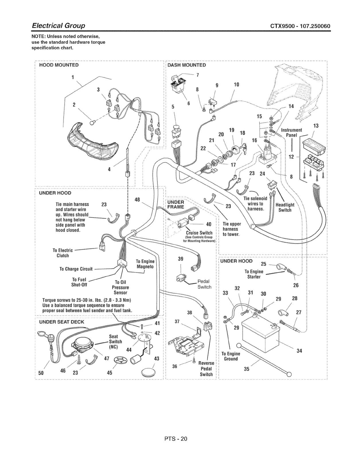
Electrical Group CTX9500 =107.250060
NOTE: UnJess noted otherwise,
use the standard hardware torque
specification chart.
HOOD MOUNTED DASH MOUNTED
7
15
PTS - 20

Electrical Group
REF NO PART NO.
47 1718981SM
48 1739708YP
49 1734025SM
50 1725302SM
51 1716329SM
QTY.
1
1
1
1
1
CTX9500 - 107.250060
DESCRiPTiON
SWITCH, Seat, Grey, NC (CE/E×port) (Used only on RMO/ACS Models)
HARNESS, Wiring (CE/Export) (Used only on RMO/ACS Models)
WIRING ASSEMBLY, All Conditions Shutdown (CE/Export) (Used only on RMO/ACS
Models)
12-VOLT OUTLET (CE/Export) (Used only on RMO/ACS Models)
SWITCH, Mower Height Adjust
Footnotes
PTS - 21
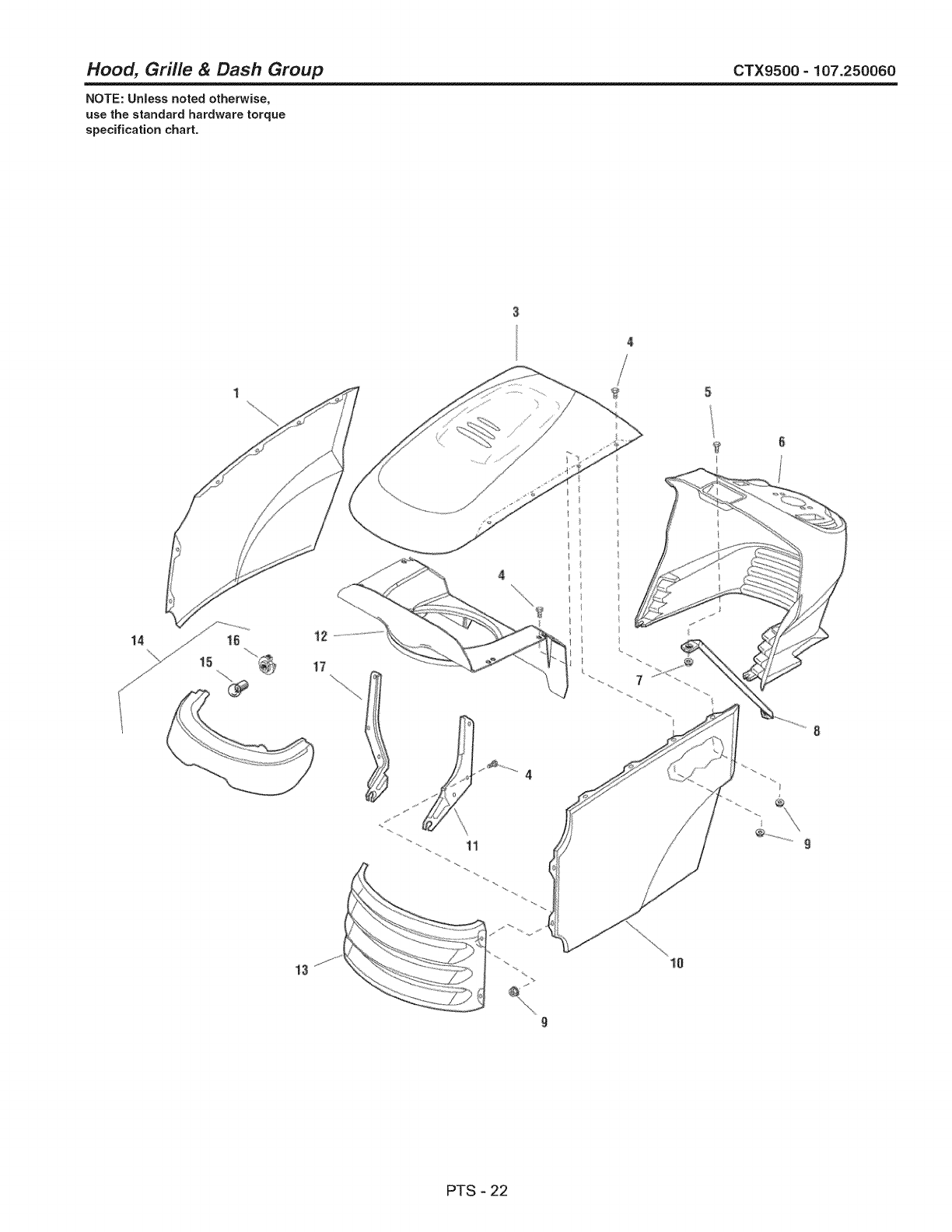
Hood, Grille & Dash Group CTX9500- 107.250060
NOTE: Unless noted otherwise,
use the standard hardware torque
specification chart.
_3
9
r
10
9
PTS - 22

Hood, Grille & Dash Group
REF NO PART NO. QTY.
1 1721804ZYP 1
3 1722110ZYP 1
4 1960295SM 12
5 1960392SM 1
6 1687054SM 1
7 1933896SM 1
8 1723123SM 1
9 1930641SM 12
10 1721803ZYP 1
11 1721808ASM 1
12 1722391ASM 1
13 1721802BRYP 1
14 1721810SM 1
15 1677371SM 4
16 1723451SM 4
17 1721809ASM 1
DESCRIPTION
PANEL, RH Side
HOOD, with Louvers
CAPSCREW, Hex Head Flange Lock, I/4-20 x 5/8
SCREW, Phillips Head, #10-24 x 1/2
DASHBOARD, RMO, Black
NUT, Hex Nylock,#10-24
ROD, Dash Support
NUT, Hex Flange Lock, 1/4-20
PANEL, LH Side
HINGE, LH
DUCT, Air Inlet
GRILLE
HEADLIGHT ASSEMBLY (Includes Ref. Nos. 15 & 16)
BULB, Headlight (Included with Ref. No. 14)
SOCKET, Headlight (Included with Ref. No. 14)
HINGE, RH
CTX9500 - 107.250060
Footnotes
PTS - 23
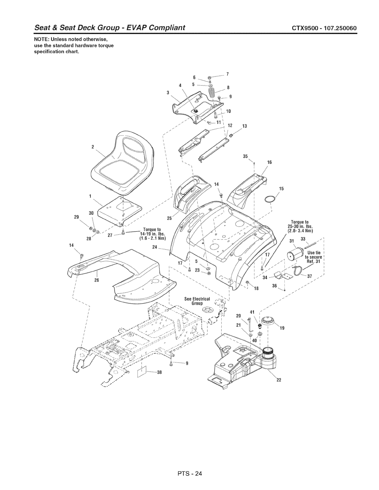
Seat & Seat Deck Group -EVAP Compliant CTX9500 - 107.250060
NOTE: Unless noted otherwise,
use the standard hardware torque
specification chart.
14
14
PTS - 24
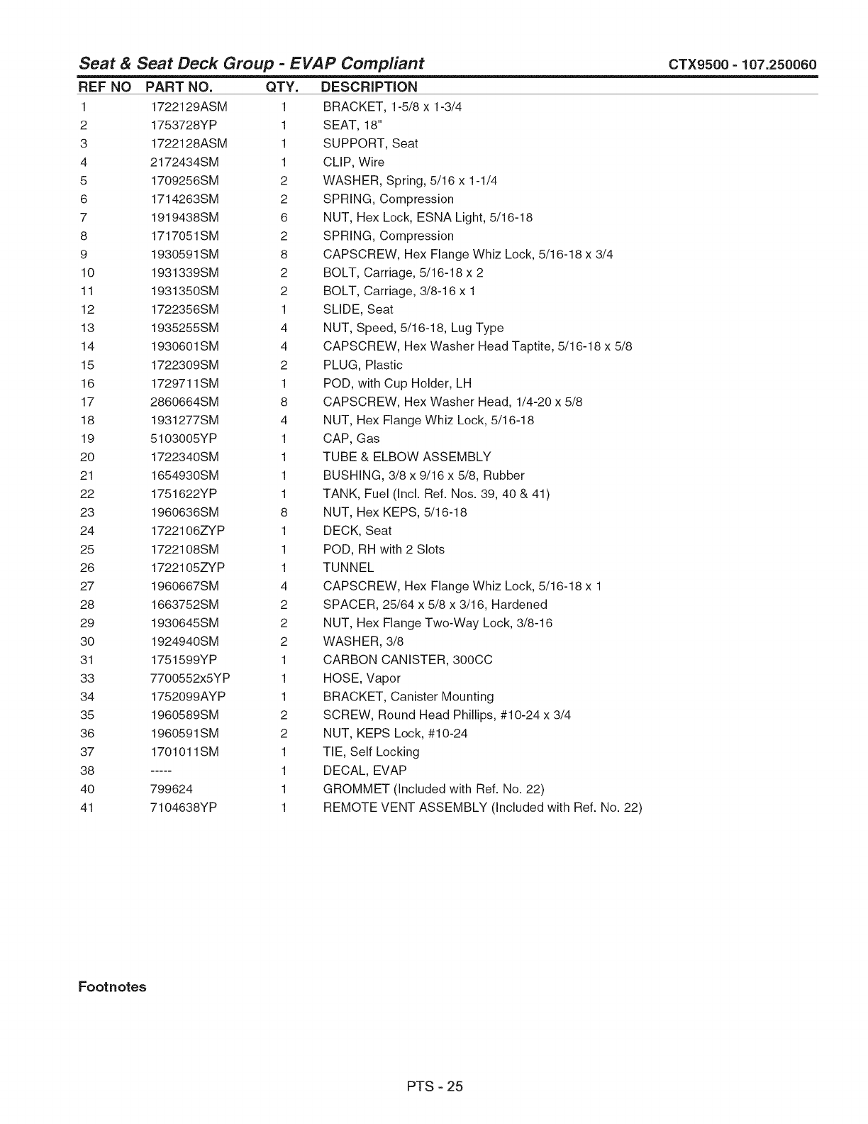
Seat & Seat Deck Group -EVAP Compliant CTX9500 - 107.250060
REF NO PART NO. QTY.
1 1722129ASM 1
2 1753728YP 1
3 1722128ASM 1
4 2172434SM 1
5 1709256SM 2
6 1714263SM 2
7 1919438SM 6
8 1717051SM 2
9 1930591SM 8
10 1931339SM 2
11 1931350SM 2
12 1722356SM 1
13 1935255SM 4
14 1930601SM 4
15 1722309SM 2
16 172971 lSM 1
17 2860664SM 8
18 1931277SM 4
19 5103005YP 1
20 1722340SM 1
21 1654930SM 1
22 1751622YP 1
23 1960636SM 8
24 1722106ZYP 1
25 1722108SM 1
26 1722105ZYP 1
27 1960667SM 4
28 1663752SM 2
29 1930645SM 2
30 1924940SM 2
31 1751599YP 1
33 7700552x5YP 1
34 1752099AYP 1
35 1960589SM 2
36 1960591SM 2
37 170101 lSM 1
38 ..... 1
40 799624 1
41 7104638YP 1
DESCRiPTiON
BRACKET, 1-5/8 x 1-3/4
SEAT, 18"
SUPPORT, Seat
CLIP, Wire
WASHER, Spring, 5/16 x 1-1/4
SPRING, Compression
NUT, Hex Lock, ESNA Light, 5/16-18
SPRING, Compression
CAPSCREW, Hex Flange Whiz Lock, 5/16-18 x 3/4
BOLT, Carriage, 5/16-18 x 2
BOLT, Carriage, 3/8-16 x 1
SLIDE, Seat
NUT, Speed, 5/16-18, Lug Type
CAPSCREW, Hex Washer Head Taptite, 5/16-18 x 5/8
PLUG, Plastic
POD, with Cup Holder, LH
CAPSCREW, Hex Washer Head, 1/4-20 x 5/8
NUT, Hex Flange Whiz Lock, 5/16-18
CAP, Gas
TUBE & ELBOW ASSEMBLY
BUSHING, 3/8 x 9/16 x 5/8, Rubber
TANK, Fuel (Incl. Ref. Nos. 39, 40 & 41)
NUT, Hex KEPS, 5/16-18
DECK, Seat
POD, RH with 2 Slots
TUNNEL
CAPSCREW, Hex Flange Whiz Lock, 5/16-18 x 1
SPACER, 25/64 x 5/8 x 3/16, Hardened
NUT, Hex Flange Two-Way Lock, 3/8-16
WASHER, 3/8
CARBON CANISTER, 300CC
HOSE, Vapor
BRACKET, Canister Mounting
SCREW, Round Head Phillips, #10-24 x 3/4
NUT, KEPS Lock, #10-24
TIE, Self Locking
DECAL, EVAP
GROMMET (Included with Ref. No. 22)
REMOTE VENT ASSEMBLY (Included with Ref. No. 22)
Footnotes
PTS - 25
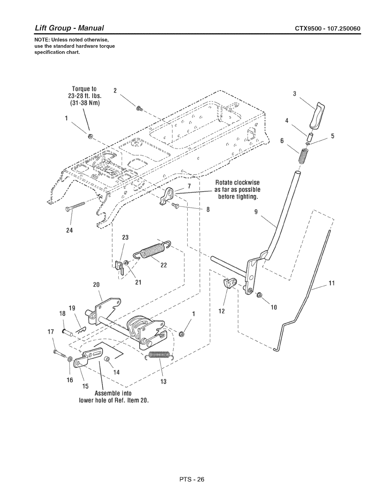
Lift Group -Manual CTX9500- 107.250060
NOTE: Unless noted otherwise,
use the standard hardware torque
specification chart.
Terqae tO
23-28 ft. _bs.
(31-38Nm}
3
PTS - 26
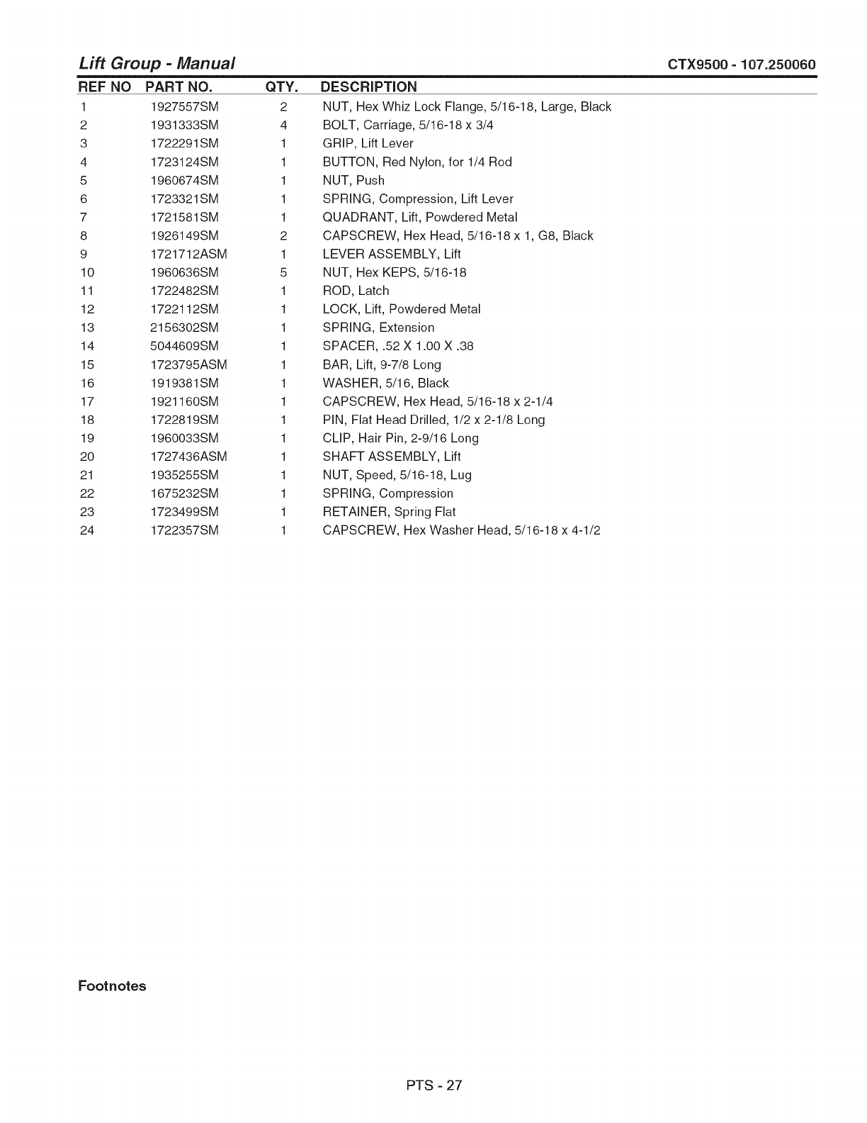
Lift Group -Manual
REF NO PART NO. QTY.
1 1927557SM 2
2 1931333SM 4
3 1722291SM 1
4 1723124SM 1
5 1960674SM 1
6 1723321SM 1
7 1721581SM 1
8 1926149SM 2
9 1721712ASM 1
10 1960636SM 5
11 1722482SM 1
12 1722112SM 1
13 2156302SM 1
14 5044609SM 1
15 1723795ASM 1
16 1919381SM 1
17 1921160SM 1
18 1722819SM 1
19 1960033SM 1
20 1727436ASM 1
21 1935255SM 1
22 1675232SM 1
23 1723499SM 1
24 1722357SM 1
DESCRiPTiON
NUT, Hex Whiz Lock Flange, 5/16-18, Large, Black
BOLT, Carriage, 5/16-18 x 3/4
GRIP, Lift Lever
BUTTON, Red Nylon, for 1/4 Rod
NUT, Push
SPRING, Compression, Lift Lever
QUADRANT, Lift, Powdered Metal
CAPSCREW, Hex Head, 5/16-18 x 1, G8, Black
LEVER ASSEMBLY, Lift
NUT, Hex KEPS, 5/16-18
ROD, Latch
LOCK, Lift, Powdered Metal
SPRING, Extension
SPACER, .52 X 1.00 X .38
BAR, Lift, 9-7/8 Long
WASHER, 5/16, Black
CAPSCREW, Hex Head, 5/16-18 x 2-1/4
PIN, Flat Head Drilled, 1/2 x 2-1/8 Long
CLIP, Hair Pin, 2-9/16 Long
SHAFT ASSEMBLY, Lift
NUT, Speed, 5/16-18, Lug
SPRING, Compression
RETAINER, Spring Flat
CAPSCREW, Hex Washer Head, 5/16-18 x 4-1/2
CTX9500 - 107.250060
Footnotes
PTS - 27
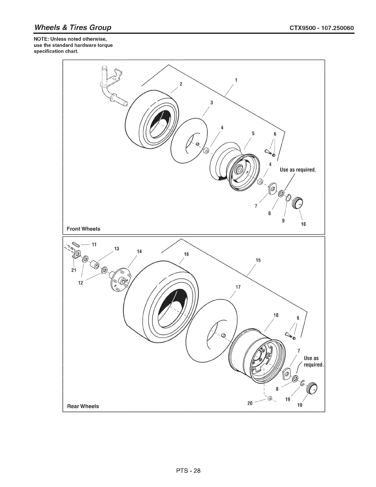
Wheels & Tires Group CTX9500- 107.250060
NOTE: Unless noted otherwise,
use the standard hardware torque
specification chart.
Front Wheels 10
15
PTS - 28
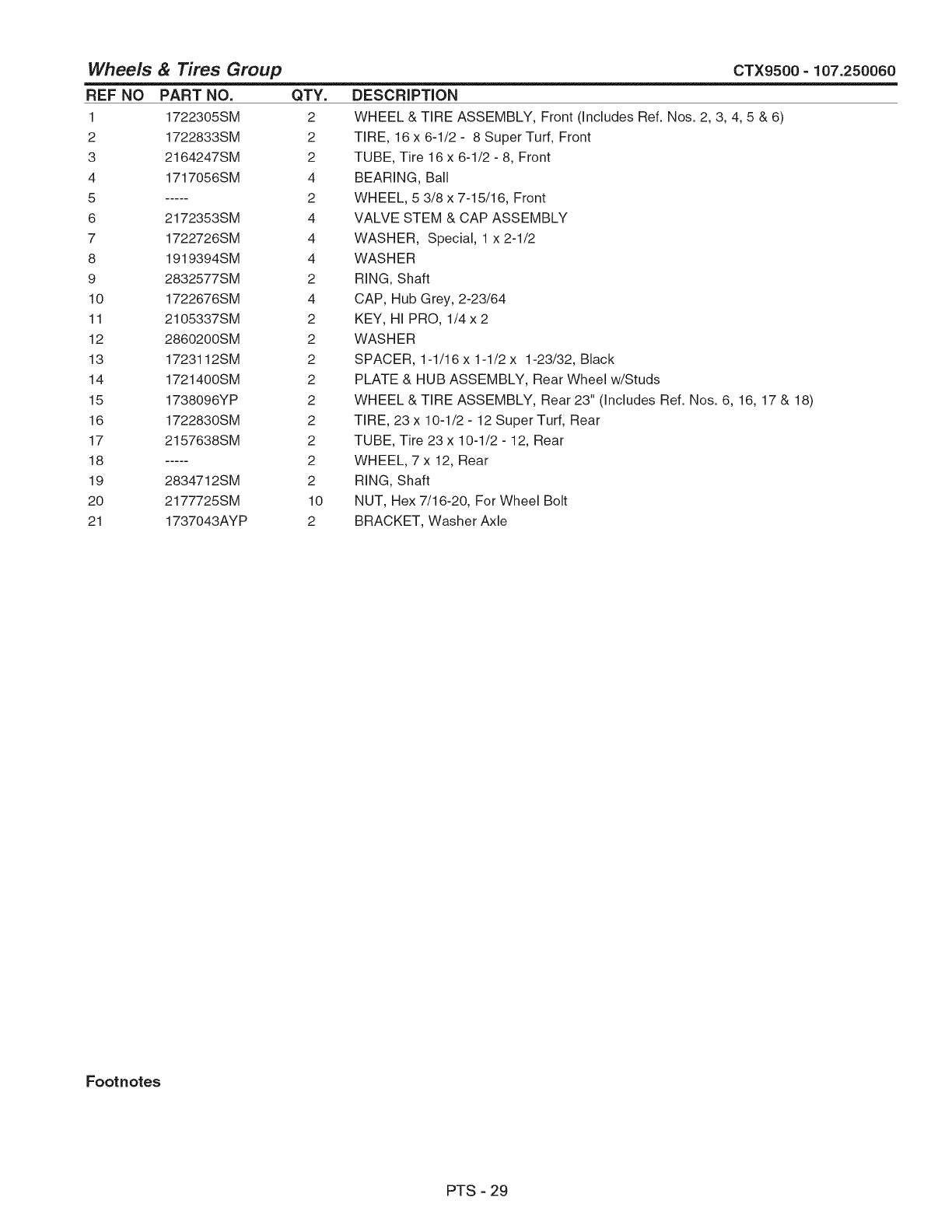
Wheels & Tires Group
REF NO PART NO. QTY.
1 1722305SM 2
2 1722833SM 2
3 2164247SM 2
4 1717056SM 4
5 ..... 2
6 2172353SM 4
7 1722726SM 4
8 1919394SM 4
9 2832577SM 2
10 1722676SM 4
11 2105337SM 2
12 2860200SM 2
13 1723112SM 2
14 1721400SM 2
15 1738096YP 2
16 1722830SM 2
17 2157638SM 2
18 ..... 2
19 2834712SM 2
20 2177725SM 10
21 1737043AYP 2
CTX9500 - 107.250060
DESCRiPTiON
WHEEL & TIRE ASSEMBLY, Front (Includes Ref. Nos. 2, 3, 4, 5 & 6)
TIRE, 16 x 6-1/2 - 8 Super Turf, Front
TUBE, Tire 16x 6-1/2 - 8, Front
BEARING, Ball
WHEEL, 5 3/8 x 7-15/16, Front
VALVE STEM & CAP ASSEMBLY
WASHER, Special, 1 x 2-1/2
WASHER
RING, Shaft
CAP, Hub Grey, 2-23/64
KEY, HI PRO, 1/4 x 2
WASHER
SPACER, 1-1/16 x 1-1/2 x 1-23/32, Black
PLATE & HUB ASSEMBLY, Rear Wheel w/Studs
WHEEL & TIRE ASSEMBLY, Rear 23" (Includes Ref. Nos. 6, 16, 17 & 18)
TIRE, 23 x 10-1/2- 12 SuperTurf, Rear
TUBE, Tire 23 x 10-1/2 - 12, Rear
WHEEL, 7 x 12, Rear
RING, Shaft
NUT, Hex 7/16-20, For Wheel Bolt
BRACKET, Washer Axle
Footnotes
PTS - 29
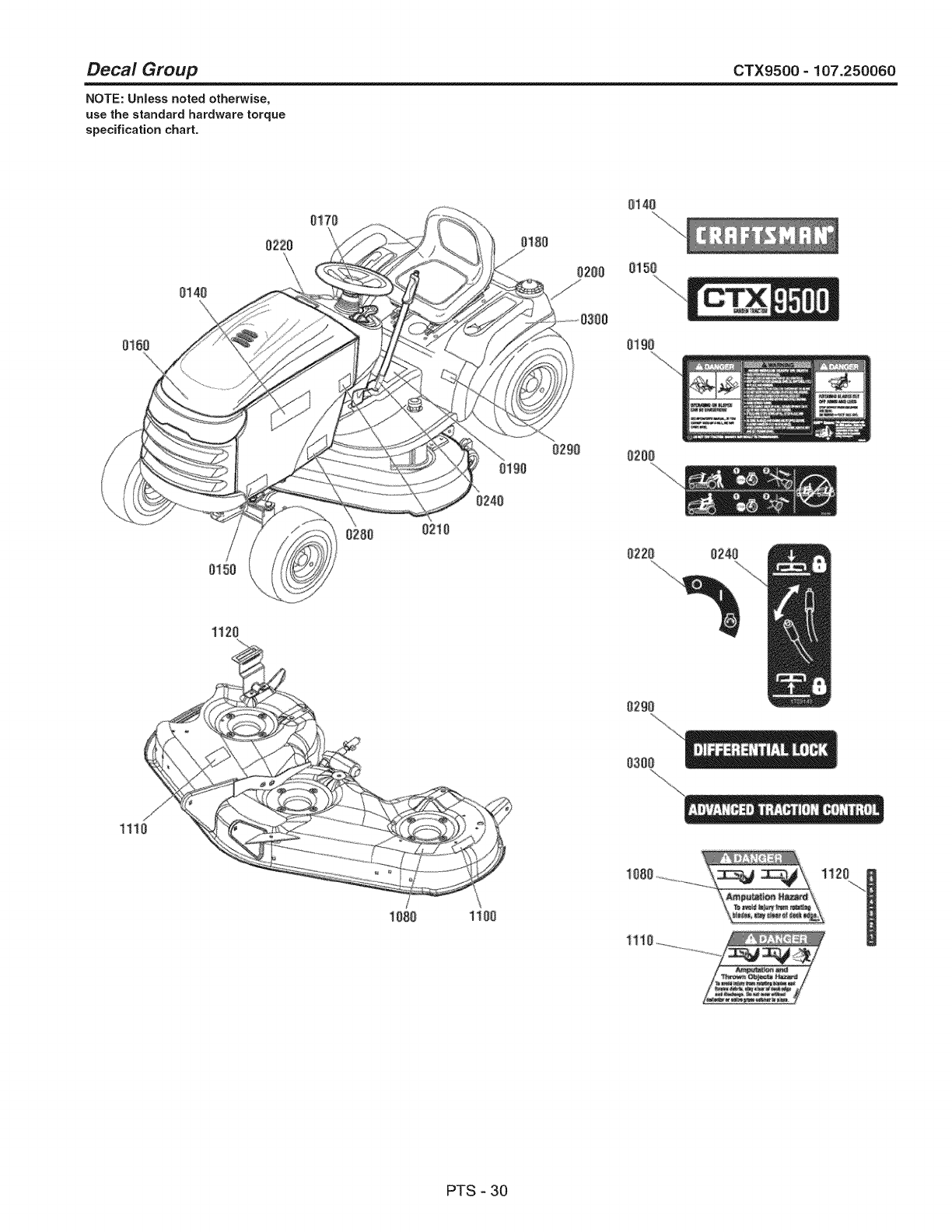
Decal Group CTX9500 =107.250060
NOTE: Unless noted otherwise,
use the standard hardware torque
specification chart.
0140
0170
0t00
0200
0140
0150
0160 019o
0150
0280 0210
0190
0240
0200
0220 0240
1120
0290
0300
1110
1080 1100
1110...........
PTS - 30

Decal Group CTX9500 =107.250060
REF NO
O140
0150
0170
0180
0190
0200
0210
0220
0240
0280
0290
0300
1080
1100
1110
1120
PART NO.
7103145YP
1753771YP
1753767YP
1753765YP
1726923SM
1723160SM
1753783YP
1722806SM
1723143YP
1753772YP
1753955YP
1753954YP
1704276SM
1753789YP
1704277SM
1721197SM
QTY.
2
2
1
1
1
1
1
1
1
2
1
1
1
1
1
1
DESCRiPTiON
DECAL
DECAL
DECAL
DECAL
DECAL
DECAL
DECAL
DECAL
DECAL
DECAL
DECAL
DECAL
DECAL
DECAL
DECAL
DECAL
Craftsman
MODEL CTX9500 Craftsman
Icon "C" Chevron Craftsman
Craftsman, Rear Seat
Tunnel Cover Danger Slopes, Blades
Transmission Release Valve
22HP Sears Service Parts
Ignition Switch Symbols
Lift Lever Symbols
26HP Craftsman
Differential Lock
Controlled Traction, Automatic
Danger Do Not Put Hands/Feet in Mower
Deck Width 52" Sears
Danger Do Not Operate without Deflector
1 2 3 4 5 6, Height of Cut White/Black
Footnotes
PTS - 31
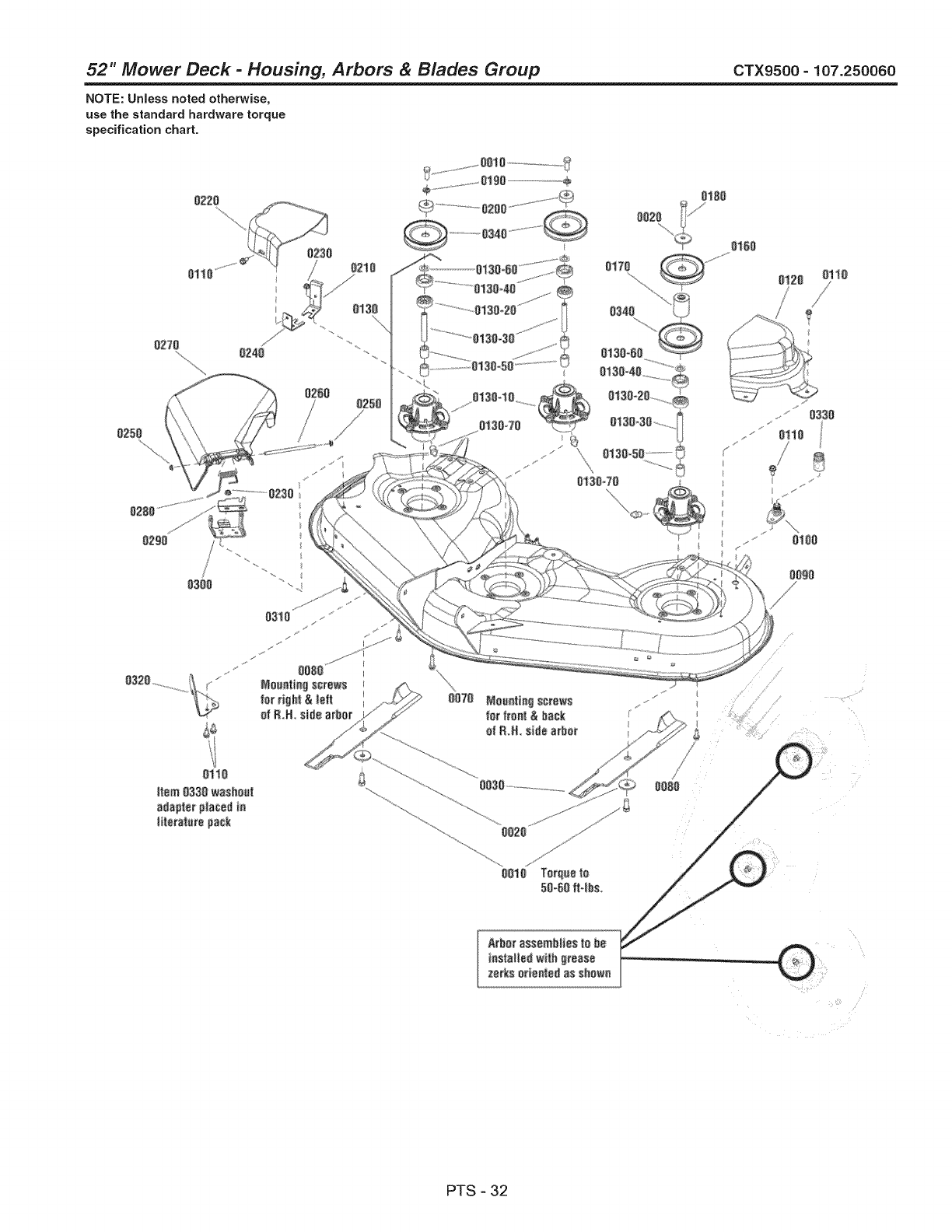
52" Mower Deck- Housing, Arbors & Blades Group CTX9500- 107.250060
NOTE: UnJess noted otherwise,
use the standard hardware torque
specification chart.
1111 Torque Io
51-61 I-Ib_.
Ikfbo_'_:_._;e_blie,,;tobe
PTS - 32
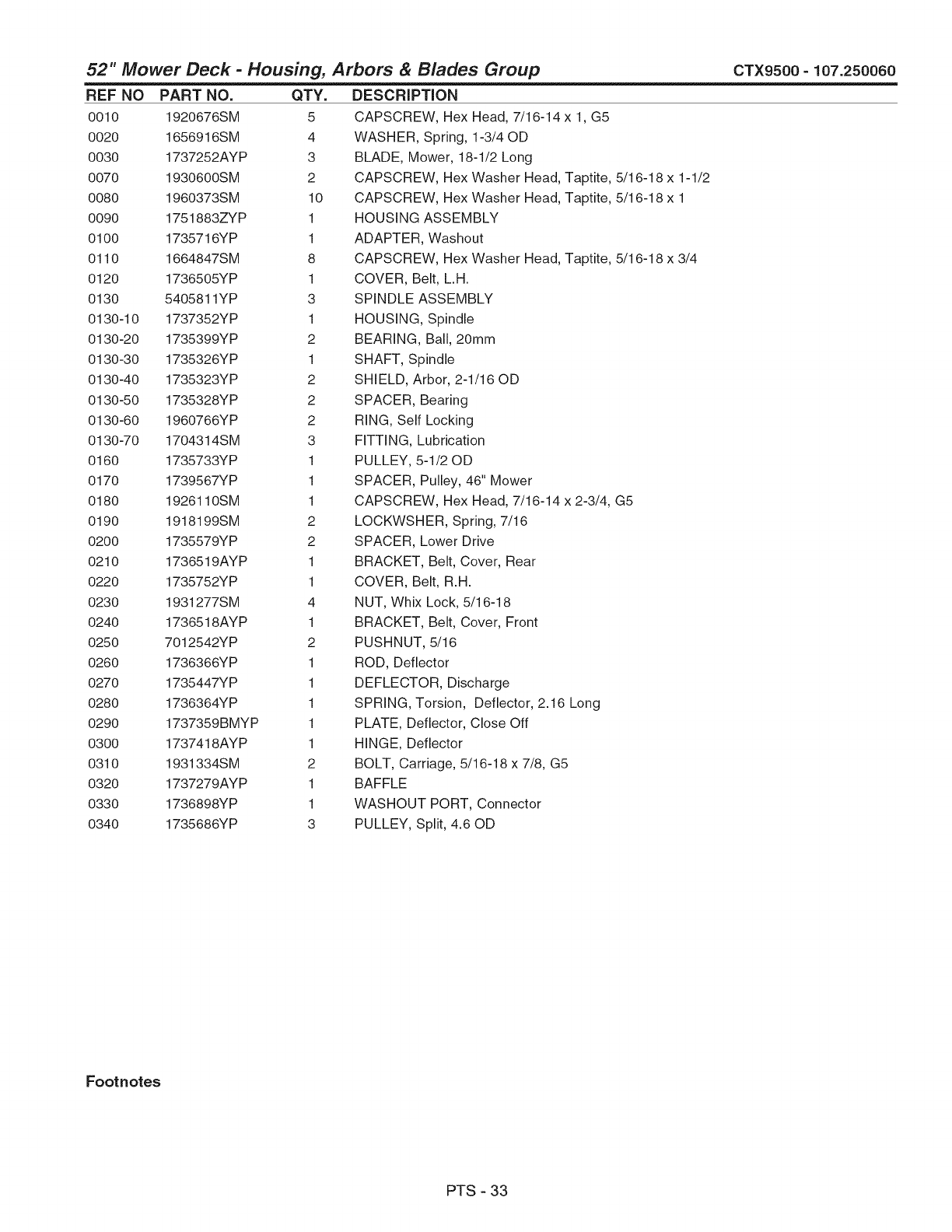
52" Mower Deck- Housing, Arbors & Blades Group CTX9500- 107.250060
REF NO PART NO. QTY.
0010 1920676SM 5
0020 1656916SM 4
0030 1737252AYP 3
0070 1930600SM 2
0080 1960373SM 10
0090 1751883ZYP 1
0100 1735716YP 1
0110 1664847SM 8
0120 1736505YP 1
0130 5405811YP 3
0130-10 1737352YP 1
0130-20 1735399YP 2
0130-30 1735326YP 1
0130-40 1735323YP 2
0130-50 1735328YP 2
0130-60 1960766YP 2
0130-70 1704314SM 3
0160 1735733YP 1
0170 1739567YP 1
0180 1926110SM 1
0190 1918199SM 2
0200 1735579YP 2
0210 1736519AYP 1
0220 1735752YP 1
0230 1931277SM 4
0240 1736518AYP 1
0250 7012542YP 2
0260 1736366YP 1
0270 1735447YP 1
0280 1736364YP 1
0290 1737359BMYP 1
0300 1737418AYP 1
0310 1931334SM 2
0320 1737279AYP 1
0330 1736898YP 1
0340 1735686YP 3
DESCRiPTiON
CAPSCREW, Hex Head, 7/16-14 x 1, G5
WASHER, Spring, 1-3/40D
BLADE, Mower, 18-1/2 Long
CAPSCREW, Hex Washer Head, Taptite, 5/16-18 x 1-1/2
CAPSCREW, Hex Washer Head, Taptite, 5/16-18 x 1
HOUSING ASSEMBLY
ADAPTER, Washout
CAPSCREW, Hex Washer Head, Taptite, 5/16-18 x 3/4
COVER, Belt, L.H.
SPINDLE ASSEMBLY
HOUSING, Spindle
BEARING, Ball, 20mm
SHAFT, Spindle
SHIELD, Arbor, 2-1/16 OD
SPACER, Bearing
RING, Self Locking
FITTING, Lubrication
PULLEY, 5-1/20D
SPACER, Pulley, 46" Mower
CAPSCREW, Hex Head, 7/16-14 x 2-3/4, G5
LOCKWSHER, Spring, 7/16
SPACER, Lower Drive
BRACKET, Belt, Cover, Rear
COVER, Belt, R.H.
NUT, Whix Lock, 5/16-18
BRACKET, Belt, Cover, Front
PUSHNUT, 5/16
ROD, Deflector
DEFLECTOR, Discharge
SPRING, Torsion, Deflector, 2.16 Long
PLATE, Deflector, Close Off
HINGE, Deflector
BOLT, Carriage, 5/16-18 x 7/8, G5
BAFFLE
WASHOUT PORT, Connector
PULLEY, Split, 4.60D
Footnotes
PTS - 33
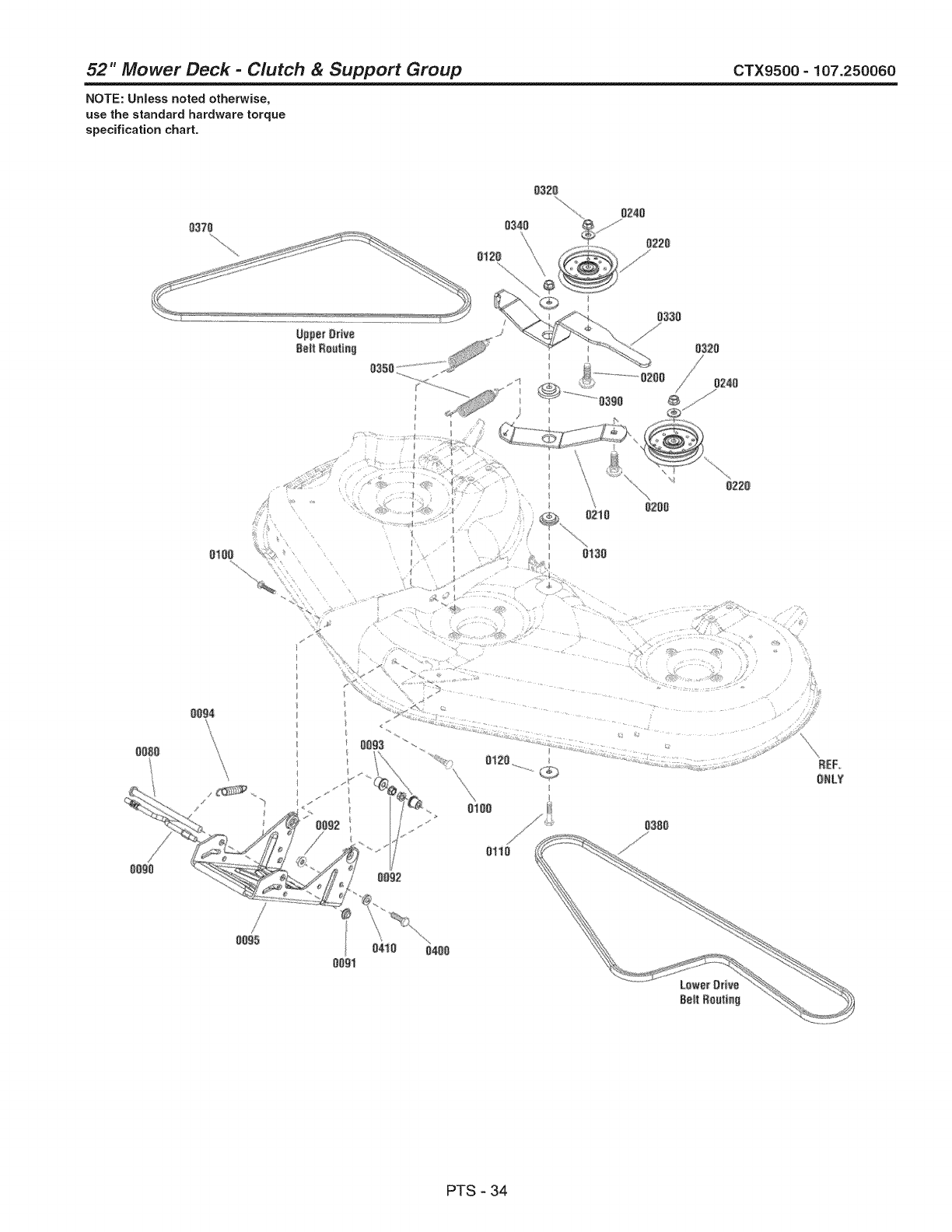
52" Mower Deck- Clutch &Support Group CTX9500- 107.250060
NOTE: Unless noted otherwise,
use the standard hardware torque
specification chart.
o37a
0320
6220
0350 .........
o
0330
032O
0240
0200
0220
OOBO
0094
OOg3
012G
oi00
0110
D380
B;EF,
ONLY
PTS - 34

52" Mower Deck- Clutch &Support Group CTX9500- 107.250060
REF NO PART NO.
0080 1713578SM
0090 1715759SM
0091 1960519SM
0092 1960687SM
0093 1732443SM
0094 2156302SM
0095 1738040AYP
0100 7091945YP
0110 1921971SM
0120 1924356SM
0130 1714255SM
0200 7091810SM
0210 1735321AYP
0220 1736540YP
0240 7091528SM
0320 7091619SM
0330 1739585AYP
0340 1930645SM
0350 1715772SM
0370 1751423YP
0380 1665450SM
0390 1739594YP
0400 5025013X8SM
0410 5044960SM
QTY.
1
1
1
3
2
1
1
2
1
2
1
2
1
2
2
2
1
1
2
1
1
1
1
1
DESCRiPTiON
ROD, 1/2 Dia. x 7-5/8
ROD, 3/8 Dia. x 8
PUSHNUT, 1/2
NUT, Hex Flange, 3/8-16
SPACER, 3/40D x 3/4 Long
SPRING, Extension, 4-1/8
HITCH, Mower
BOLT, Carriage,, 3/8C X1-1/2 GR5 YZ
CAPSCREW, Hex Head, 3/8-16 x 1-3/4, G5
WASHER, 3/8, 1/20D
SPACER,l-I/20D
USE - 91810 BOLT, Carriage, 3/8C X1-3/4, G5
ARM, Idler, Lower
PULLEY, Idler, 46 & 52" Mowers
WASHER, Flat, 3/8 x .875
NUT, Whiz, 3/8
ARM, Idler, Upper
NUT, Hex Flange, Two Way Locking, 3/8-16
SPRING, Extension, 5-1/4
V-BELT, HA, 68.10
V-BELT, HA, 87.20
SPACER, 1-3/40D
BOLT, 3/8-16 x 1, G5
SPACER, 3/8 x 1 x 1/4
Footnotes
PTS - 35

52" Mower Deck- Height Adjust Group CTX9500 - 107.250060
NOTE: Unless noted otherwise,
use the standard hardware torque
specification chart.
0270
0300 0530
0050
0090 01i0
\
0020
o100
oogo
..........0040
0030
0050
0060 0050
03:10
0110
0500...............04,50
0400
0410
/0430
0490
0420
0050
................0450
0100 0110
0!30
0080
0110
0050
0080
0100
0050 .......
0090
PTS - 36
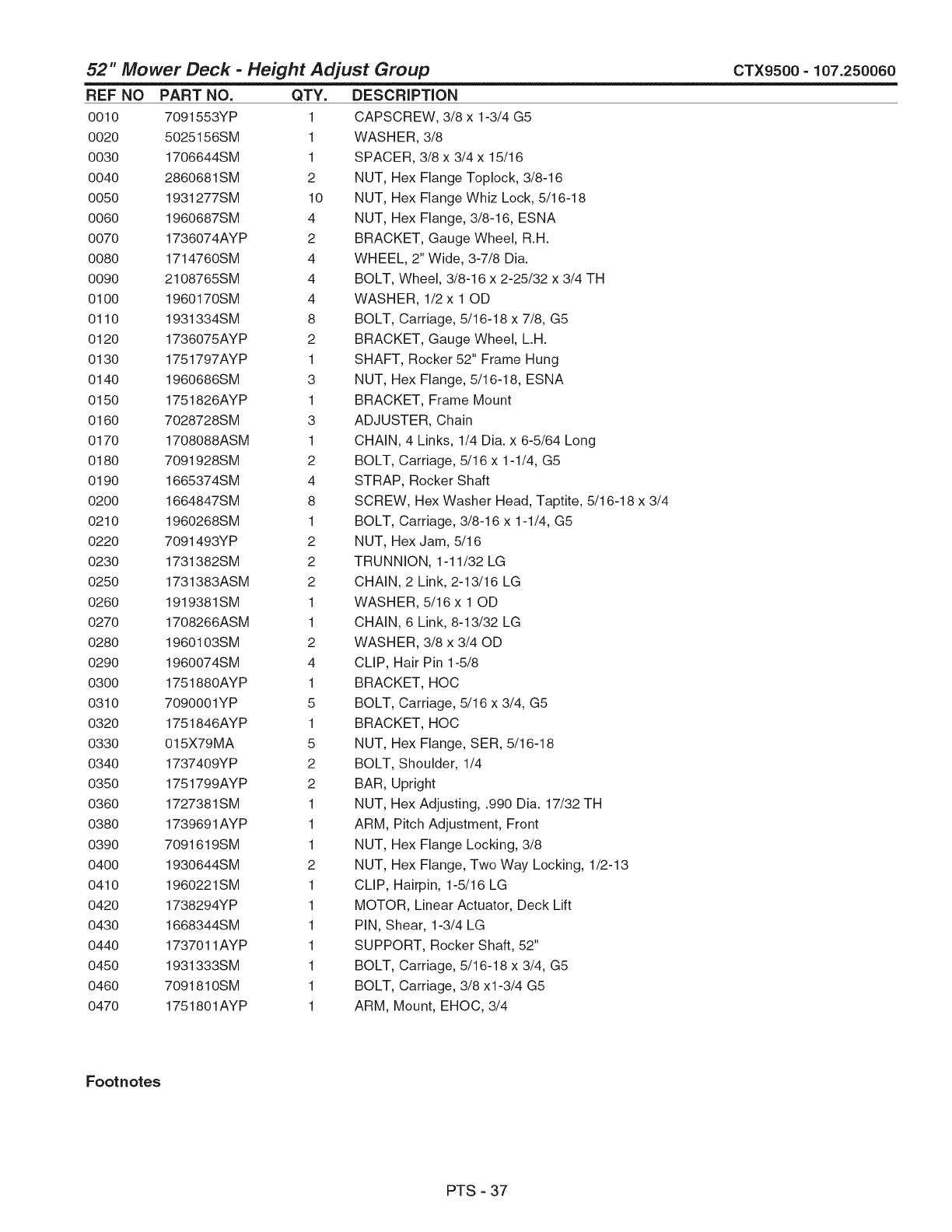
52" Mower Deck- Height Adjust Group CTX9500 =107.250060
REF NO PART NO. QTY.
0010 7091553YP 1
0020 5025156SM 1
0030 1706644SM 1
0040 2860681 SM 2
0050 1931277SM 10
0060 1960687SM 4
0070 1736074AYP 2
0080 1714760SM 4
0090 2108765SM 4
0100 1960170SM 4
0110 1931334SM 8
0120 1736075AYP 2
0130 1751797AYP 1
0140 1960686SM 3
0150 1751826AYP 1
0160 7028728SM 3
0170 1708088ASM 1
0180 7091928SM 2
0190 1665374SM 4
0200 1664847SM 8
0210 1960268SM 1
0220 7091493YP 2
0230 1731382SM 2
0250 1731383ASM 2
0260 1919381SM 1
0270 1708266ASM 1
0280 1960103SM 2
0290 1960074SM 4
0300 1751880AYP 1
0310 7090001YP 5
0320 1751846AYP 1
0330 015X79MA 5
0340 1737409YP 2
0350 1751799AYP 2
0360 1727381SM 1
0380 1739691AYP 1
0390 7091619SM 1
0400 1930644SM 2
0410 1960221SM 1
0420 1738294YP 1
0430 1668344SM 1
0440 1737011AYP 1
0450 1931333SM 1
0460 7091810SM 1
0470 1751801AYP 1
DESCRiPTiON
CAPSCREW, 3/8 x 1-3/4 G5
WASHER, 3/8
SPACER, 3/8 x 3/4 x 15/16
NUT, Hex Flange Toplock, 3/8-16
NUT, Hex Flange Whiz Lock, 5/16-18
NUT, Hex Flange, 3/8-16, ESNA
BRACKET, Gauge Wheel, R.H.
WHEEL, 2" Wide, 3-7/8 Dia.
BOLT, Wheel, 3/8-16 x 2-25/32 x 3/4 TH
WASHER, 1/2 x 10D
BOLT, Carriage, 5/16-18 x 7/8, G5
BRACKET, Gauge Wheel, L.H.
SHAFT, Rocker 52" Frame Hung
NUT, Hex Flange, 5/16-18, ESNA
BRACKET, Frame Mount
ADJUSTER, Chain
CHAIN, 4 Links, 1/4 Dia. x 6-5/64 Long
BOLT, Carriage, 5/16 x 1-1/4, G5
STRAP, Rocker Shaft
SCREW, Hex Washer Head, Taptite, 5/16-18 x 3/4
BOLT, Carriage, 3/8-16 x 1-1/4, G5
NUT, Hex Jam, 5/16
TRUNNION, 1-11/32 LG
CHAIN, 2 Link, 2-13/16 LG
WASHER, 5/16 x 10D
CHAIN, 6 Link, 8-13/32 LG
WASHER, 3/8 × 3/40D
CLIP, Hair Pin 1-5/8
BRACKET, HOC
BOLT, Carriage, 5/16 x 3/4, G5
BRACKET, HOC
NUT, Hex Flange, SER, 5/16-18
BOLT, Shoulder, 1/4
BAR, Upright
NUT, Hex Adjusting, .990 Dia. 17/32 TH
ARM, Pitch Adjustment, Front
NUT, Hex Flange Locking, 3/8
NUT, Hex Flange, Two Way Locking, 1/2-13
CLIP, Hairpin, 1-5/16 LG
MOTOR, Linear Actuator, Deck Lift
PIN, Shear, 1-3/4 LG
SUPPORT, Rocker Shaft, 52"
BOLT, Carriage, 5/16-18 x 3/4, G5
BOLT, Carriage, 3/8 xl-3/4 G5
ARM, Mount, EHOC, 3/4
Footnotes
PTS - 37
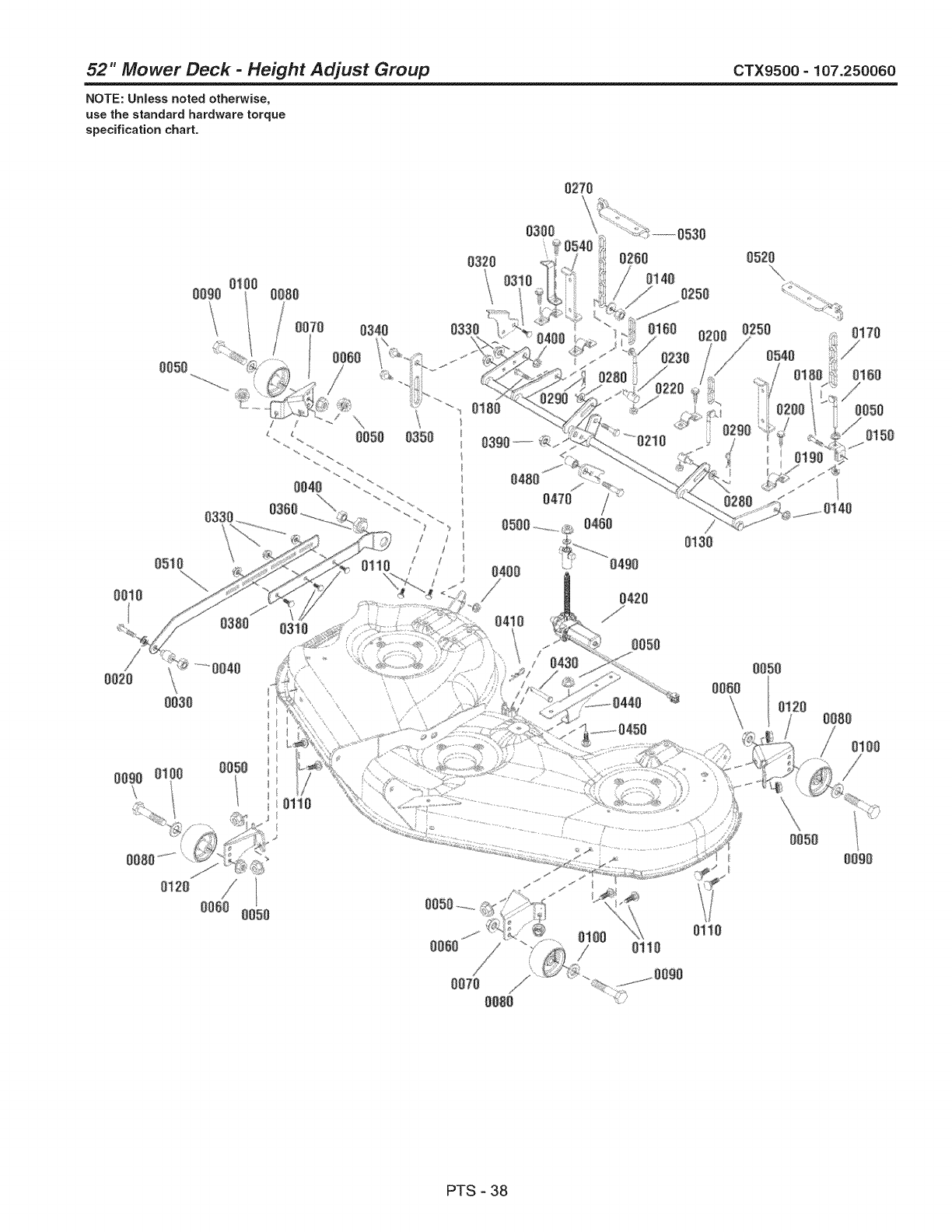
52" Mower Deck- Height Adjust Group CTX9500 - 107.250060
NOTE: Unless noted otherwise,
use the standard hardware torque
specification chart.
0270
0300 0530
0050
0090 01i0
\
0020
o100
oogo
..........0040
0030
0050
0060 0050
03:10
0110
0500...............04,50
0400
0410
/0430
0490
0420
0050
................0450
0100 0110
0!30
0080
0110
0050
0080
0100
0050 .......
0090
PTS - 38

52" Mower Deck -Height Adjust Group
REF NO PART NO. QTY. DESCRiPTiON
0480 7014334YP 1 SPACER, 5/80D x 13/16 L
0490 1921319SM 1 WASHER, 1/4 x 5/80D
0500 1960757SM 1 NUT, Hex, LH Thread, 1/4-20
0510 1739554AYP 1 ARM, Pitch Adjustment
0520 1727103ASM 1 HANGER, LH.
0530 1727102ASM 1 HANGER, R.H.
0540 1737219AYP 2 UPSTOP, Rear
CTX9500 - 107.250060
Footnotes
PTS - 39
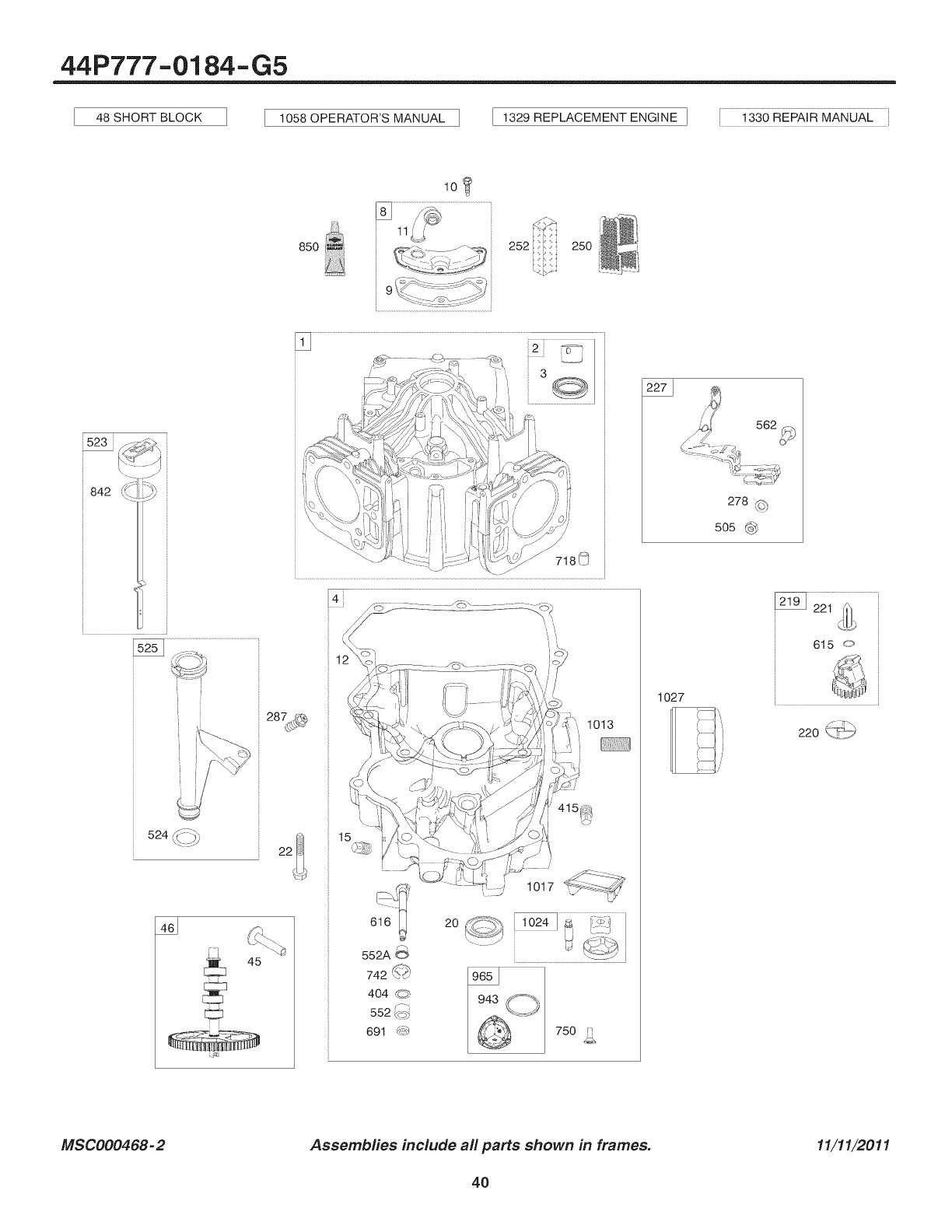
44P777-0184-G5
48 SHORT BLOCK 1058 OPERATOR'S MANUAL I 1329 REPLACEMENT ENGINE I 1330 REPAI R MANUAL
lO_
850 252 250
523i
842 _.
i _ L J
_,' ,_ .....................................................
278 ,_
505
4_
20
1013
1027
615 o
MSC000468-2 Assembfies include all parts shown in frames. 11/11/2011
4O
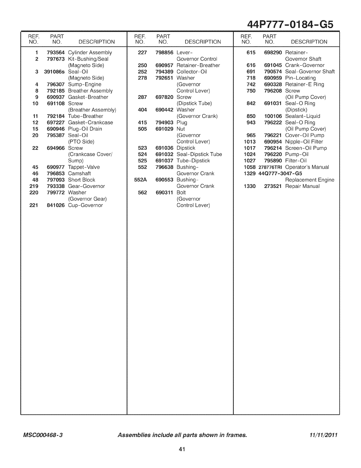
44P777-0184-G5
REF. PART REF. PART REF. PART
NO. NO. DESCRIPTION NO. NO. DESCRIPTION NO. NO. DESCRIPTION
227 798856 615 6982901
2
793564
797673
391086s
4 796307
8 792185
9 690937
10 691108
11 792184
12 697227
15 690946
20 795387
22 694966
45 690977
46 796853
48 797093
219 793338
220 799772
221 841026
Cylinder Assembly
Kit-Bushing/Seal
(Magneto Side)
Seal-Oil
(Magneto Side)
Sump-Engine
Breather Assembly
Gasket-Breather
Screw
(Breather Assembly)
Tube-Breather
Gasket-Crankcase
Plug-Oil Drain
Seal-Oil
(PTO Side)
Screw
(Crankcase Cover/
Sump)
Tappet-Valve
Camshaft
Short Block
Gear-Governor
Washer
(Governor Gear)
Cup-Governor
Lever-
Governor Control
250 690957 Retainer-Breather
252 794389 Collector-Oil
278 792651 Washer
(Governor
Control Lever)
287 697820 Screw
(Dipstick Tube)
404 690442 Washer
(Governor Crank)
415 794903 Plug
505 691029 Nut
(Governor
Control Lever)
523 691036 Dipstick
524 691032 Seal-Dipstick Tube
525 691037 Tube-Dipstick
552 796638 Bushing-
Governor Crank
552A 690553 Bushing-
Governor Crank
562 690311 Bolt
(Governor
Control Lever)
Retainer-
Governor Shaft
616 691045 Crank-Governor
691 790574 Seal-Governor Shaft
718 690959 Pin-Locating
742 690328 Retainer-E Ring
750 796208 Screw
(Oil Pump Cover)
842 691031 SeaI-O Ring
(Dipstick)
850 100106 Sealant-Liquid
943 796222 Seal-O Ring
(Oil Pump Cover)
965 796221 Cover-Oil Pump
1013 690954 Nipple-Oil Filter
1017 796214 Screen-Oil Pump
1024 796220 Pump-Oil
1027 795890 Filter-Oil
1058 278776TRI Operator's Manual
1329 44Q777-3047-G5
Replacement Engine
1330 273521 Repair Manual
MSC000468-3 Assembfies include all parts shown in frames. 11/11/2011
41
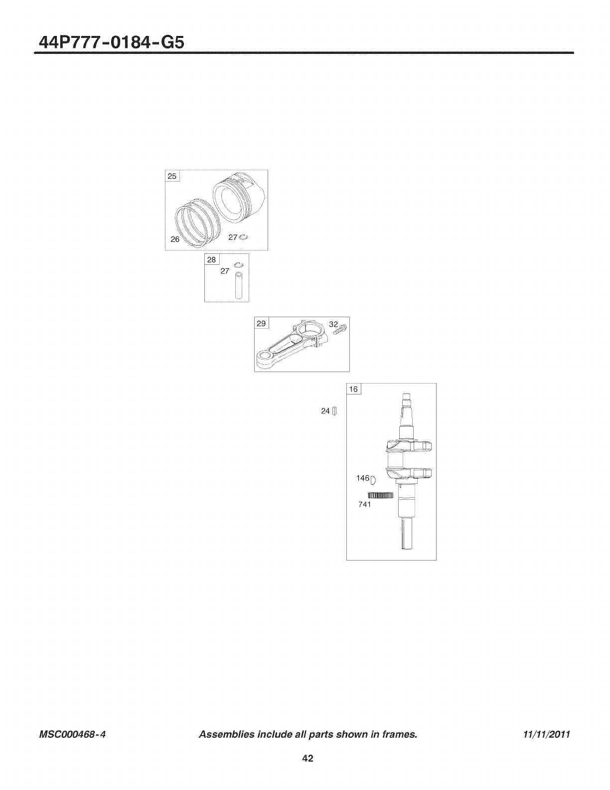
44P777-0184-G5
i25i
26
2 _'_ -_
29J _] _ 32A,,_
s$:i: -'"
L'221_
248
146[}
741
MSC000468- 4 Assembfies include all parts shown in frames.
42
11/11/2011

44P777-0184-G5
REF. PART REF. PART REF. PART
NO. NO. DESCRIPTION NO. NO. DESCRIPTION NO. NO. DESCRIPTION
26 79356116 796237
24 222698s
25 793560
Crankshaft
Key-Flywheel
(Aluminum)
Piston Assembly
(Standard)
....... Note .....
793563 Piston
Assembly
(.020" Oversize)
Ring Set
(Standard)
....... Note .....
792073 Ring Set
(.020" Oversize)
27 690975 Lock-Piston Pin
28 696581 Pin-Piston
29 796209 Rod-Connecting
32 690976 Screw
(Connecting Rod)
146 690979 Key-Timing
741 690980 Gear-Timing
MSC000468-5 Assemblies include all parts shown in frames. 11/11/2011
43
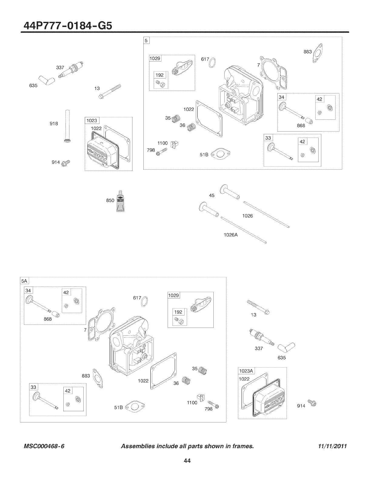
44P777-0184-G5
635
918
i i
J_, .fl/J,,
1192 ii _'/" ;_
883
1022
36 ,_ 868
J
85O 45
,_ 1026 "\\_\_" _.
1026A \'\_--.q _%
5Ai
1022 11022
337
635
914_"_
MSC000468- 6 Assembfies include all parts shown in frames. 11/11/2011
44
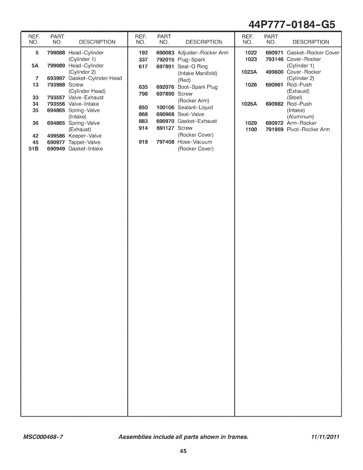
44P777-0184-G5
REF. PART REF. PART REF. PART
NO. NO. DESCRIPTION NO. NO. DESCRIPTION NO. NO. DESCRIPTION
5
5A
7
13
799088 Head-Cylinder
(Cylinder 1)
799089 Head-Cylinder
(Cylinder 2)
693997 Gasket-Cylinder Head
793988 Screw
(Cylinder Head)
793557 Valve-Exhaust
793556 Valve-intake
192 690083 Adjuster-Rocker Arm
337 792015 Plug-Spark
617 697891 SeaI-O Ring
(Intake Manifold)
(Red)
635 692076 Boot-Spark Plug
798 697890 Screw
(Rocker Arm)
1022
1023
1023A
1026
1026A
690971 Gasket-Rocker Cover
793146 Cover-Rocker
(Cylinder 1)
499600 Cover-Rocker
(Cylinder 2)
690981 Rod-Push
(Exhaust)
(Steel)
690982 Rod-Push
33
34
35 694865 Spring-Valve
(Intake)
36 694865 Spring-Valve
(Exhaust)
42 499586 Keeper-Valve
45 690977 Tappet-Valve
51B 690949 Gasket-Intake
850 100106 Sealant-Liquid
868 690968 Seal-Valve
883 690970 Gasket-Exhaust
914 691127 Screw
(Rocker Cover)
918 797408 Hose-Vacuum
(Rocker Cover)
(Intake)
(Aluminum)
1029 690972 Arm-Rocker
1100 791959 Pivot-Rocker Arm
MSC000468- 7 Assemblies include all parts shown in frames. 11/11/2011
45
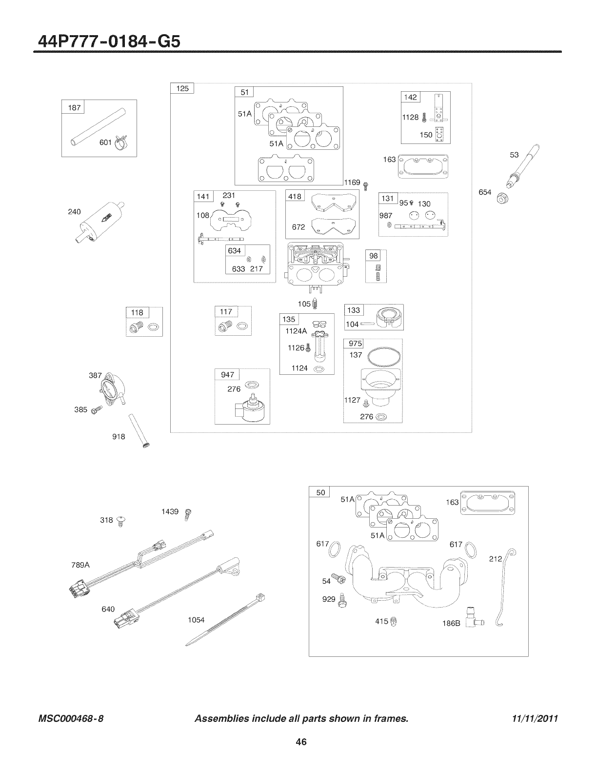
44P777-0184-G5
8/ 601
240 /
387
918
[_
soi_
163
231
108 _\
633 217
--T ........................................
947 i
276
1169
hr_
105_J
1124A @_
1126g!i_
\J
1124 ,,<))
si
137
I
654
1439 ,_
318 _
789A _ S':_j_ ..._J_A
640 _._,_ _"
_' 10s4
_oj
929_
415_ 186B _'
MSC000468- 8 Assembfies include all parts shown in frames. 11/11/2011
46
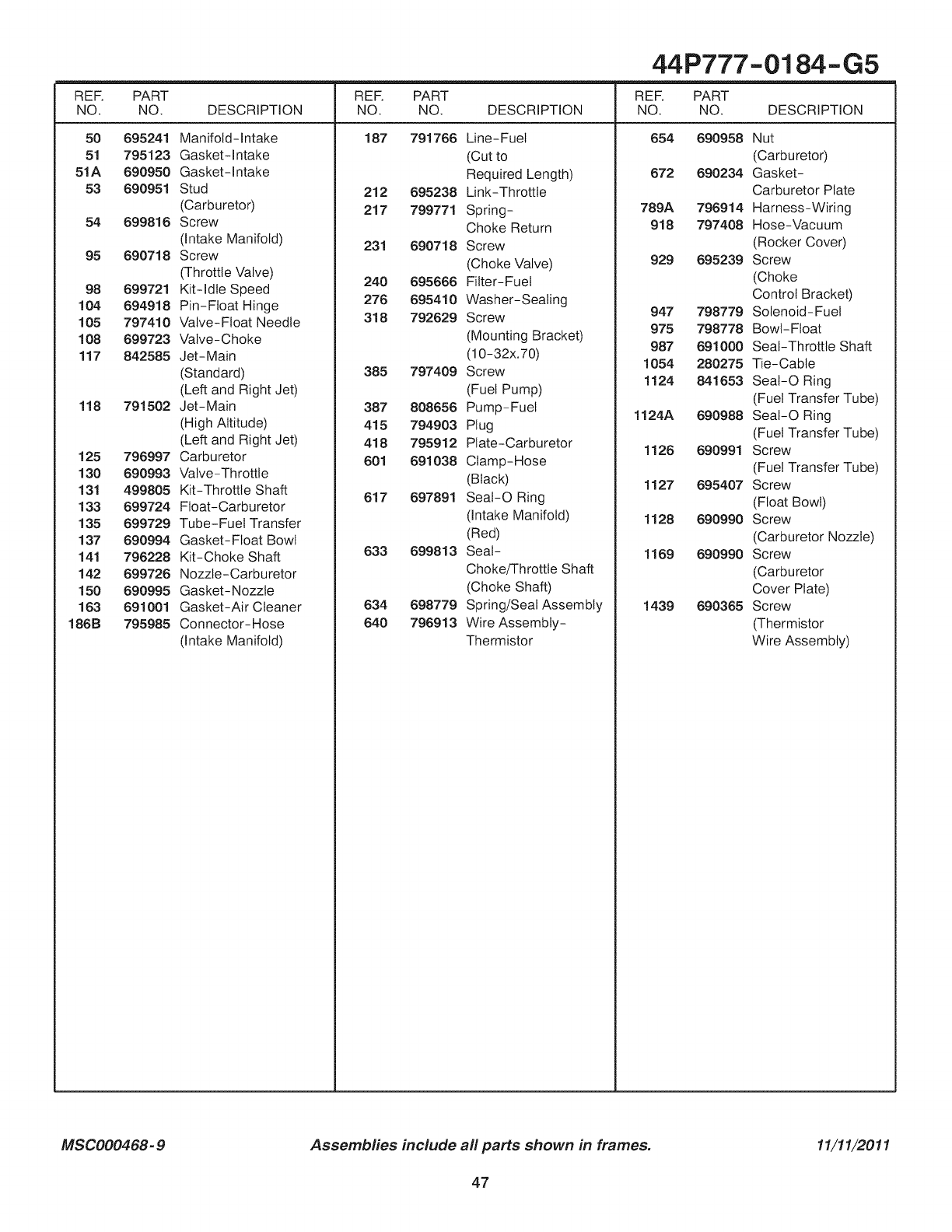
44P777-0184-G5
REF. PART REF. PART
NO. NO. DESCRIPTION NO. NO. DESCRIPTION DESCRIPTION
187 79176650 695241
51 795123
51A 690950
53 690951
54 699816
95 690718
98 699721
104 694918
105 797410
108 699723
117 842585
118 791502
125 796997
130 690993
131 499805
133 699724
135 699729
137 690994
141 796228
142 699726
150 690995
163 691001
186B 795985
Manifold-intake
Gasket-Intake
Gasket-Intake
Stud
(Carburetor)
Screw
(intake Manifold)
Screw
(Throttle Valve)
Kit-idle Speed
Pin-Float Hinge
Valve-Float Needle
Valve-Choke
Jet-Main
(Standard)
(Left and Right Jet)
Jet-Main
(High Altitude)
(Left and Right Jet)
Carburetor
Valve-Throttle
Kit-Throttle Shaft
Float-Carburetor
Tube-Fuel Transfer
Gasket-Float Bowl
Kit-Choke Shaft
Nozzle-Carburetor
Gasket-Nozzle
Gasket-Air Cleaner
Connector-Hose
(Intake Manifold)
Line-Fuel
(Cutto
Required Length)
212 695238 Link-Throttle
217 799771 Spring-
Choke Return
231 690718 Screw
(Choke Valve)
240 695666 Filter-Fuel
276 695410 Washer-Sealing
318 792629 Screw
(Mounting Bracket)
(10-32x.70)
385 797409 Screw
(Fuel Pump)
387 808656 Pump-Fuel
415 794903 Plug
418 795912 Plate-Carburetor
601 691038 Clamp-Hose
(Black)
617 697891 SeaI-O Ring
(Intake Manifold)
(Red)
633 699813 Seal-
Choke/Throttle Shaft
(Choke Shaft)
634 698779 Spring/Seal Assembly
640 796913 Wire Assembly-
Thermistor
RER PART
NO. NO.
654 690958
672 690234
789A 796914
918 797408
929 695239
947 798779
975 798778
987 691000
1054 280275
1124 841653
1124A 690988
1126 690991
1127 695407
1128 690990
1169 690990
1439 690365
Nut
(Carburetor)
Gasket-
Carburetor Plate
Harness-Wiring
Hose-Vacuum
(Rocker Cover)
Screw
(Choke
Control Bracket)
Solenoid-Fuel
Bowl-Float
Seal-Throttle Shaft
Tie-Cable
Seai-O Ring
(Fuel Transfer Tube)
SeaI-O Ring
(Fuel Transfer Tube)
Screw
(Fuel Transfer Tube)
Screw
(Float Bowl)
Screw
(Carburetor Nozzle)
Screw
(Carburetor
Cover Plate)
Screw
(Thermistor
Wire Assembly)
MSC000468-9 Assembfies include all parts shown in frames. 11/11/2011
47
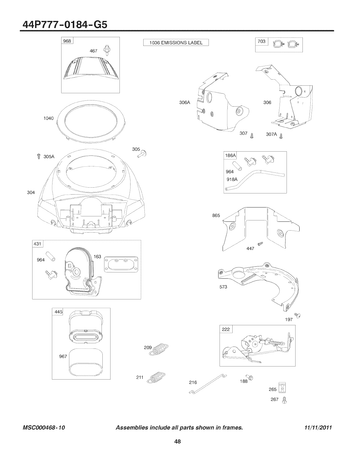
44P777-0184-G5
467
1036 EMISSIONS LABEL
305_
306A 306
307 4_ 307A
304
865
431
IY
967
573
C
447
197
211
_ 216_
267 (_
MSC000468-10 Assembfies include all parts shown in frames. 11/11/2011
48
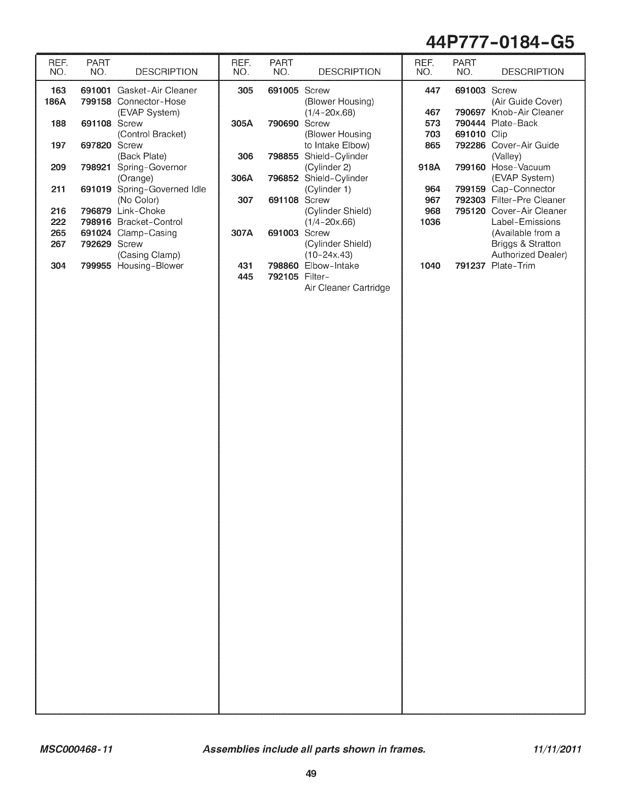
REF.
NO.
163
186A
188
197
209
211
216
222
265
267
304
44P777-0184-G5
PART REF. PART REF. PART
NO. DESCRIPTION NO. NO. DESCRIPTION NO. NO. DESCRIPTION
305 691005 447 691003691001
799158
691108
697820
798921
691019
796879
798916
691024
792629
799955
Gasket-Air Cleaner
Connector-Hose
(EVAP System)
Screw
(Control Bracket)
Screw
(Back Plate)
Spring-Governor
(Orange)
Spring-Governed Idle
(No Color)
Link-Choke
Bracket-Control
Clamp-Casing
Screw
(Casing Clamp)
Housing-Blower
Screw
(Blower Housing)
(1/4-20x.68)
305A 790690 Screw
(Blower Housing
to Intake Elbow)
306 798855 Shield-Cylinder
(Cylinder 2)
306A 796852 Shield-Cylinder
(Cylinder 1)
307 691108 Screw
(Cylinder Shield)
(1/4-20x.66)
307A 691003 Screw
(Cylinder Shield)
(10-24x.43)
431 798860 Elbow-Intake
445 792105 Filter-
Air Cleaner Cartridge
467 790697
573 790444
703 691010
865 792286
918A 799160
964 799159
967 792303
968 795120
1036
1040 791237
Screw
(Air Guide Cover)
Knob-Air Cleaner
Plate-Back
Clip
Cover-Air Guide
(Valley)
Hose-Vacuum
(EVAP System)
Cap-Connector
Fitter-Pre Cleaner
Cover-Air Cleaner
Label-Emissions
(Available from a
Briggs & Stratton
Authorized Dealer)
Plate-Trim
MSC000468-11 Assembfies include all parts shown in frames. 11/11/2011
49
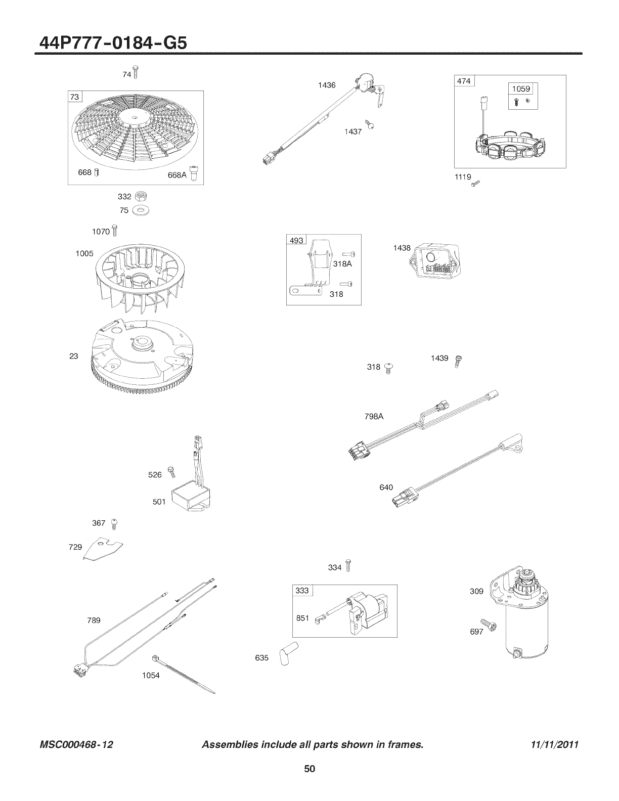
44P777-0184-G5
74_
1070 _l
1005
1437
1436
1119
/
23
789
526
501
635
1439
318
J\
798A _'i_' _ff:f _ ....
334
9991
851
ZJ
MSC000468-12 Assembfies include all parts shown in frames. 11/11/2011
5O
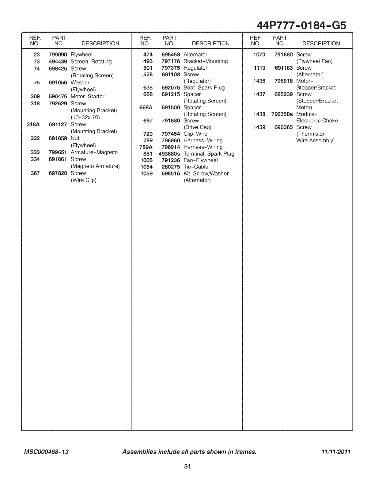
44P777-0184-G5
REF. PART REF. PART REF. PART
NO. NO. DESCRIPTION NO. NO. DESCRIPTION NO. NO. DESCRIPTION
23 799090 Flywheel
73 494439 Screen-Rotating
74 698425 Screw
(Rotating Screen)
75 691056 Washer
(Flywheel)
309 590476 Motor-Starter
318 792629 Screw
(Mounting Bracket)
(10-32x.70)
318A 691127 Screw
(Mounting Bracket)
332 691059 Nut
(Flywheel)
333 799651 Armature-Magneto
334 691061 Screw
(Magneto Armature)
367 697820 Screw
(Wire Clip)
474 696458 Alternator
493 797176 Bracket-Mounting
501 797375 Regulator
526 691108 Screw
(Regulator)
635 692076 Boot-Spark Plug
668 691215 Spacer
(Rotating Screen)
668A 691500 Spacer
(Rotating Screen)
697 791680 Screw
(Drive Cap)
729 797454 Clip-Wire
789 796860 Harness-Wiring
789A 796914 Harness-Wiring
851 493880s Terminal-Spark Plug
1005 791236 Fan-Flywheel
1054 280275 Tie-Cable
1059 698516 Kit-Screw/Washer
(Alternator)
1070 791680 Screw
(Flywheel Fan)
1119 691183 Screw
(Alternator)
1436 796918 Motor-
Stepper/Bracket
1437 695239 Screw
(Stepper/Bracket
Motor)
1438 796350s Module-
Electronic Choke
1439 690365 Screw
(Thermistor
Wire Assembly)
MSC000468-13 Assemblies include all parts shown in frames. 11/11/2011
51
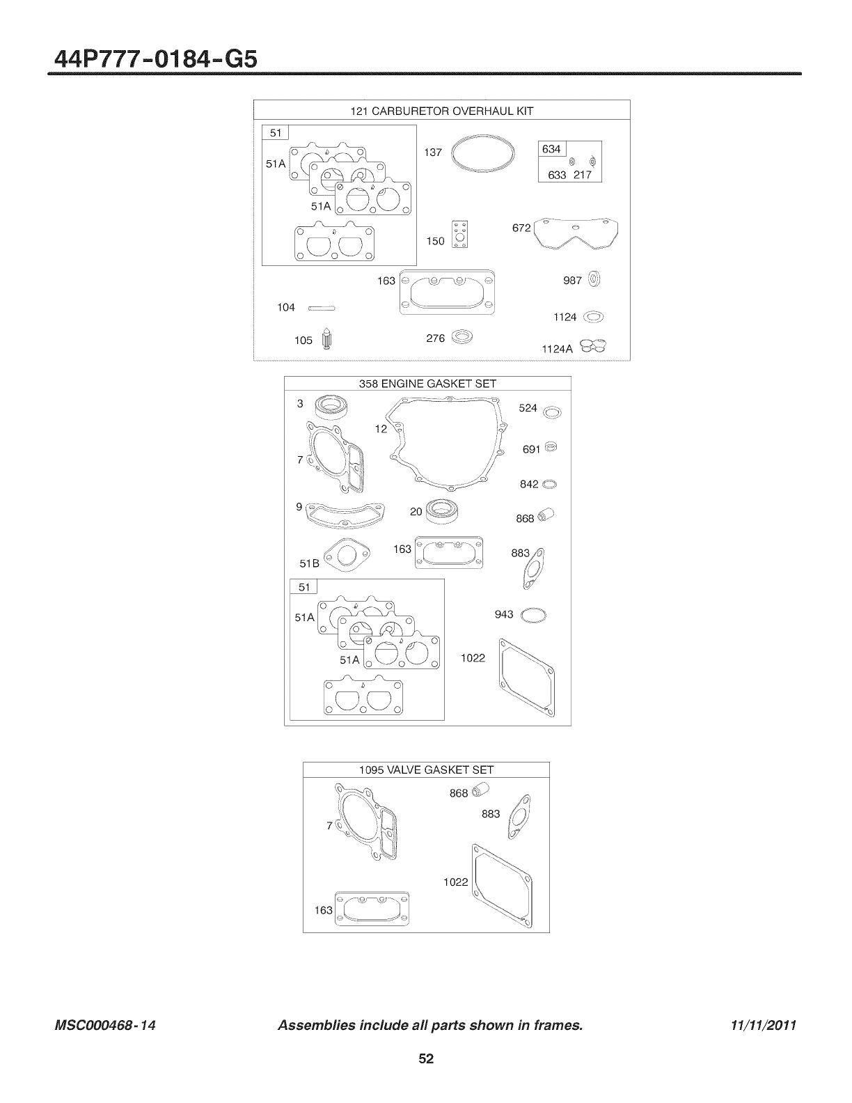
44P777-0184-G5
121 CARBURETOR OVERHAUL KiT
137 634_®
633 217
672
150
163 987 ]_i
104 _:::_ 1124 _- _._
105 [_] 276 @-_ C-_._
1124A _><J
358 ENGINE GASKET SET
524 A:.
20 868 _
163
51B
943 z- -_,
51A 1022
1095 VALVE GASKET SET
868db
883
1022
MSC000468-14 Assembfies include aft parts shown in frames. 11/11/2011
52
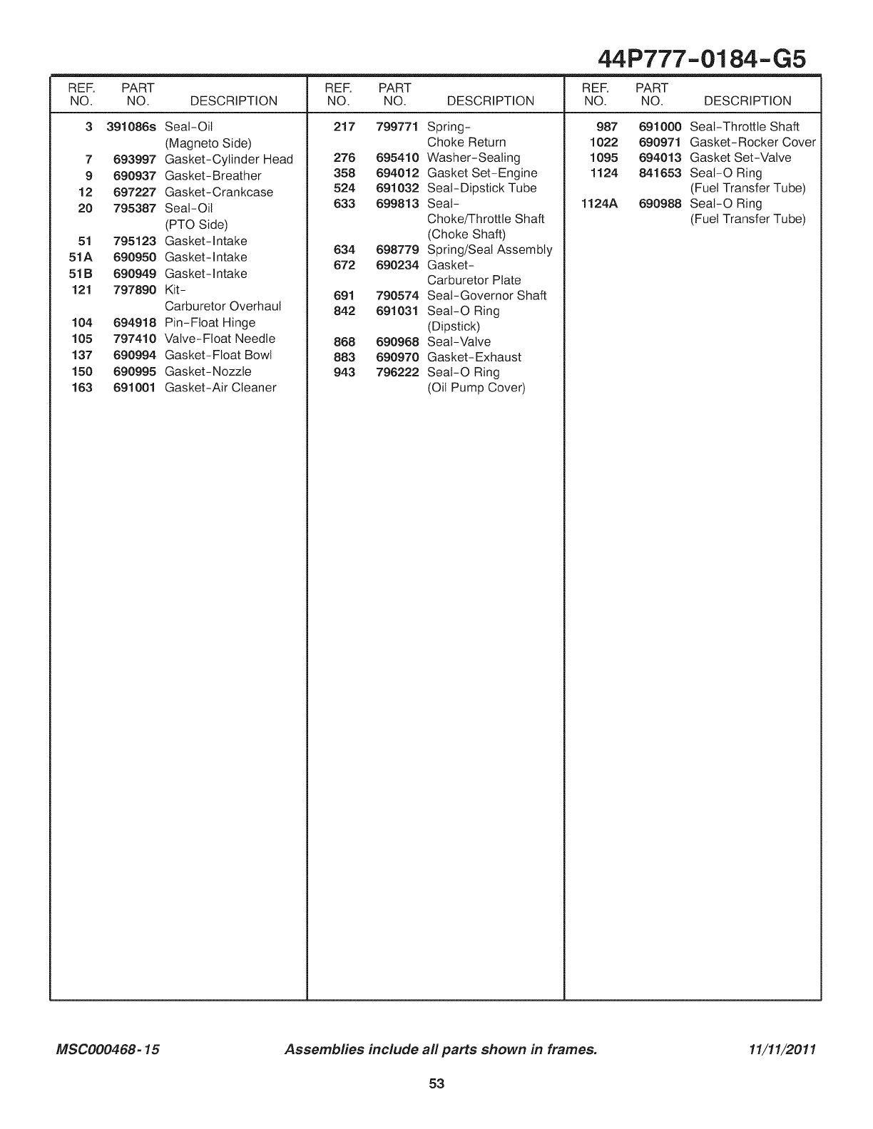
44P777-0184-G5
REF. PART REF. PART REF. PART
NO. NO. DESCRIPTION NO. NO. DESCRIPTION NO. NO. DESCRIPTION
3 391086s 217 799771
7 693997
9 690937
12 697227
20 795387
51 795123
51A 690950
51B 690949
121 797890
104 694918
105 797410
137 690994
150 690995
163 691001
Seal-Oil
(Magneto Side)
Gasket-Cylinder Head
Gasket-Breather
Gasket-Crankcase
Seal-Oil
(PTO Side)
Gasket-Intake
Gasket-Intake
Gasket-Intake
Kit -
Carburetor Overhaul
Pin-Float Hinge
Valve-Float Needle
Gasket-Float Bowl
Gasket-Nozzle
Gasket-Air Cleaner
Spring-
Choke Return
276 695410 Washer-Sealing
358 694012 Gasket Set-Engine
524 691032 Seal-Dipstick Tube
633 699813 Seal-
Choke/Throttle Shaft
(Choke Shaft)
634 698779 Spring/Seal Assembly
672 690234 Gasket-
Carburetor Plate
691 790574 Seal-Governor Shaft
842 691031 SeaI-O Ring
(Dipstick)
868 690968 Seal-Valve
883 690970 Gasket-Exhaust
943 796222 SeaI-O Ring
(Oil Pump Cover)
987
1022
1095
1124
1124A
691000 Seal-Throttle Shaft
690971 Gasket-Rocker Cover
694013 Gasket Set-Valve
841653 SeaI-O Ring
(Fuel Transfer Tube)
690988 SeaI-O Ring
(Fuel Transfer Tube)
MSC000468-15 Assembfies include all parts shown in frames. 11/11/2011
53

Hardwareidentification& TorqueSpecifications
Torque Specification Chart
FORSTANDARDMETRICMACHINEHARDWARE(Tolerance± 20%)
Property
Class
SizeOf
Hardware
5.88
13.44
26.4
44,64
5.2
7.7
15
26
42
64
89
126
169
217
326
435
590
759
988
M3
M4
M5
M6
M7
M8
MIO
M12
M14
M16
M18
M20
M22
M24
M27
M30
M33
M36
M39
in/Ibs
ft/Ibs Nm.
.56
1.28
2.5O
4.3
7.1
10.5
21
36
58
88
121
171
230
295
435
59O
8OO
1030
1340
®
Class8.8
in/Ibs
ft/Ibs Nm.
13.44 1.28
30.72 2.90
6O.96 5.75
7.3 9.9
12.1 !6.5
17.7 24
35 48
81 83
101 132
147 200
292 275
298 390
399 530
497 375
733 995
995 1350
1349 1830
1740 2360
2249 3050
in/Ibs
ft_bs Nm.
!9.2 1.80
43.44 4.!0
5.97 8.10
16.3 14
18.9 23
25 34
50 67
88.2 117
136 185
21O 285
287 390
495 550
559 745
798 960
1932 1400
1461 1900
1902 2580
2441 33!0
3183 4290
in/Ibs
fl/Ibs
22.92
52.56
7.15
12.1
19.9
29
59
183
182
250
348
488
856
848
1239
1881
2278
2835
3798
The guides and ruler furnished below are designed to
help you select the appropriate hardware.
Nm.
2.15
4.95
9.7
16.5
27
4O
81
140
220
340
470
66O
89O
1!40
1680
2280
3090
3980
5150
jillIIIIjllllIIIIIIII
0 10 20 30
©
Nu_Mj8
Thread
Diameter(ram)
Inside Threads
Diameter(in) per inch
Nut, 1/2-16
oI
,I,J,I, ,I,J,I,
IIIIII
40 50 60 70 80 90 loo
_r__iameter
Body Length_
Screw, iris= 1.25 x 25
Thread Distancebetween Body
Diameter(mm) threads(mm) Length(ram)
Body Threads Body
Diameter per rich Length(in)
Screw, 1/2= 16 x 2
34
Standard Hardware Sizing
When a washer or nut is identified as1/2" (M8), this is
the Nominal siz& meaning the inside diameteris 1/2 inch
(8ram metric thread diameter); if asecond number is present
it represents the threads per inch (distance between threads).
When bolt or capscrew is identified as1/2 = 16 x 2" (M8 - 1.25 ×50 ),
this means the Nominal size, or body diameter is 1/2 inch (8mm
metric thread diameter), the second number,16, represents the
threads per inch, (1.25 thread diameter).The final number is the
body length of the bolt or screw, 2 inches (50ram).
Torque Specification Chart
FORSTANDARDMACHINEHARDWARE(Tolerance±20%)
=:°'°@ 0 ©
SAEGrade28AEGrade5 8AEGrade8
SizeOf in/Ibs in/Ibs in/Ibs
Hardware ft/ibs Nm. ft/ibs Nm. fifths Nm.
8-32
8-36
10-24
10-32
1/4-20
1/4-28
5/16-18
5/16-24
3/8-16
3/8-24
7/16-14
7/16-20
1/2-13
1/2-20
9/16-12
9/16-18
5/8-11
5/8-18
3/4-10
3/4-16
7/8-9
7/8-14
1-8
1-12
19 2.1
20 2.3
27 3.1
3! 3.5
66 7.6
76 8.6
11 15.0
12 183
28 27.2
23 31.3
38 40.8
35 47.6
58 68.0
55 74.8
65 88.4
75 102.0
98 122.4
188 136
188 217.6
188 244.8
148 190.4
155 210.8
220 299.2
248 326.4
1. These torque
30 3.4
31 3.5
43 4.9
49 5.5
810,9
18 13.6
17 23.1
19 25.8
38 40.8
35 47.6
50 68.0
55 74.8
75 102.0
98 122.4
118 149.6
128 163.2
158 204.0
188 244.8
268 353.6
388 408.0
488 544.0
448 598.4
588 788.8
840 870.4
41 4.6
43 4.9
60 6.8
68 7.7
12 16.3
14 19.0
25 34.0
29 34.0
45 61.2
58 68.0
78 95.2
88 108.8
118 149.6
128 163.2
158 204.0
178 231.2
228 299.2
248 326.4
388 525.0
420 571.2
688 816.0
688 897.6
988 1,244.0
1,888 1,360.0
NOTES
values are to be used for all hardware
excluding: Iocknuts, self-tapping screws, thread forming
screws, sheet metal screws and socket head setscrews.
2. Recommended seating torque values for Iocknuts:
a. for prevailing torque Iocknuts - use 65% of grade5
torques.
b. for flange whizmock nuts and screws - use t 35% of
grade 5 torques.
3. Unless otherwise noted on assembly drawings, all torque
values must meet this specification.
Common Hardware Types
HexHeadCapscrew
CarriageBolt
Washer
Lockwasher
HexNut
Wrench & Fastener Size Guide
oo©©
1/4" Bolt Oh"Nut _16" SO_ Or Nut 3./8" BOlt Or Net 7116" 80it Or NUt
W_snch--7!16" Wrench--I/2" Wrench_/16" Wrench (Bolt)_5/8"
Wrench (Net)--11/16 _
M6 BaH or Net M8 BeJt or Net MlO Bolt or Net M12 Bolt Or Net
Wrerlch--lOrnm W_nch--13mm Wl_rtch--17ram Wrench--19mrn
1/2" BO_ Or NUt
Wrench--3/4"
M14 Belt 01" Nut
Wrench--22 turn
PTS - 54

Manual Del Due_o
CRRFTSMRH°
CTX 9500 Tractor de Jardin
Modelo N°
107.250060 (27HP brutos Briggs & Stratton con Cortacesped de 52 pulg.)
Para obtener respuestas a sus preguntas
sobre este producto, Ilame al: Linea de ayuda
de Sears Craftsman 1-800-659-5917.
Sears Brands Management Corporation, Hoffman Estates, IL 60179 EE. UU
Visite nuestro sitio Web de Craftsman: www.craftsman.com


Tapa delantera ............................................................................................................ I
Seguridad del operador ............................................................................................. 4
Caracteristicas y controles ..................................................................................... 10
Funcionarniento ........................................................................................................ 14
Pruebas del sisterna de interbloqueo de seguridad ............................................ 14
IVlantenirniento .......................................................................................................... 19
Soluci6n de problemas ............................................................................................ 30
Especificaciones ...................................................................................................... 32
Garantia ..................................................................................................................... 33
Acuerdos de proteccibn para reparaciones .......................................................... 34
Repuestos ........................................................................................................... PTS-1
Gracias por haber adquirido este cortacesped CRAFTSMAN de alta calidad. Le agradecemos la confianza que
ha depositado en la marca CRAFTSMAN. Si usa y realiza el mantenimiento del equipo de conformidad con las
instrucciones de este manual, su producto CRAFTSMAN le ofrecera muchos a_os de funcionamiento fiable.
Este manual contiene informacion de seguridad para advertirle sobre los peligros y riesgos asociados con el
cortacesped y como evitarlos. Este producto y sus accesorios aprobados estan dise_ados solamente para cortar
cesped o retirar nieve, y no tienen otra finalidad. Es importante que lea y comprenda estas instrucciones con
detenimiento antes de proceder a arrancar o hacer funcionar este equipo. Conserve estas instrucciones originales
para consultarlas en el futuro.
Donde encontrarnos
No tendra que buscar mucho para encontrar el servicio y mantenimiento para su cortacesped CRAFTSMAN. Existen
distribuidores de servicio tecnico autorizados en todo el mundo que ofrecen un servicio de calidad. Puede ponerse
en contacto con el Servicio al Cliente Ilamando al (800) 659-5917, o Iocalizar un distribuidor en Internet en www.
craftsman.com.
Cortacesped
N0mero de modelo
N0mero de serie
Motor
Corte del tipo de modelo
Fecha de codigo
Fecha de compra
3
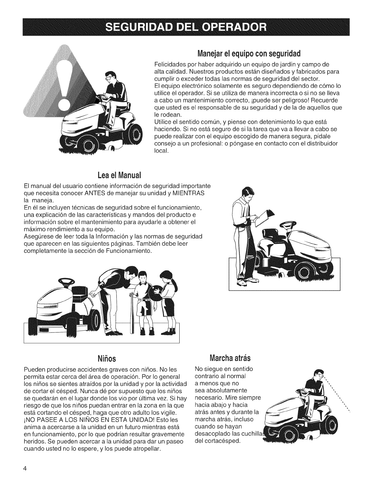
Manejarel equipoconseguridad
Felicidades por haber adquirido un equipo de jardin y campo de
alta calidad. Nuestros productos estan dise_ados y fabricados para
cumplir o exceder todas las normas de seguridad del sector.
El equipo electronico solamente es seguro dependiendo de como Io
utilice el operador. Si se utiliza de manera incorrecta o si no se Ileva
a cabo un mantenimiento correcto, ipuede ser peligroso! Recuerde
que usted es el responsable de su seguridad y de la de aquellos que
le rodean.
Utilice el sentido comun, y piense con detenimiento Io que esta.
haciendo. Si no esta seguro de si la tarea que va a Ilevar a cabo se
puede realizar con el equipo escogido de manera segura, pidale
consejo a un profesionah o pongase en contacto con el distribuidor
local.
Leael Manual
El manual del usuario contiene informacion de seguridad importante
que necesita conocer ANTES de manejar su unidad y MIENTRAS
la maneja.
En el se incluyen tecnicas de seguridad sobre el funcionamiento,
una explicacion de las caracteristicas y mandos del producto e
informacion sobre el mantenimiento para ayudarle a obtener el
maximo rendimiento a su equipo.
AsegL]rese de leer toda la Informacion y las normas de seguridad
que aparecen en las siguientes paginas. Tambien debe leer
completamente la seccion de Funcionamiento.
Ni5os
Pueden producirse accidentes graves con ni_os. No les
permita estar cerca del area de operacion. Por Io general
los ni_os se sientes atraidos por la unidad y por la actividad
de cortar el cesped. Nunca de por supuesto que los ni_os
se quedaran en el lugar donde los vio por L]ltima vez. Si hay
riesgo de que los ni_os puedan entrar en la zona en la que
esta cortando el cesped, haga que otro adulto los vigile.
iNO PASEE A LOS NINOS EN ESTA UNIDAD! Esto les
anima a acercarse a la unidad en un futuro mientras esta
en funcionamiento, por Io que podrian resultar gravemente
heridos. Se pueden acercar a la unidad para dar un paseo
cuando usted no Io espere, y los puede atropellar.
Marchaarras
No siegue en sentido
contrario al normal
a menos que no
sea absolutamente
necesario. Mire siempre
hacia abajo y hacia
atras antes y durante la
marcha atras, incluso
cuando se hayan
desacoplado las
del cortacesped.
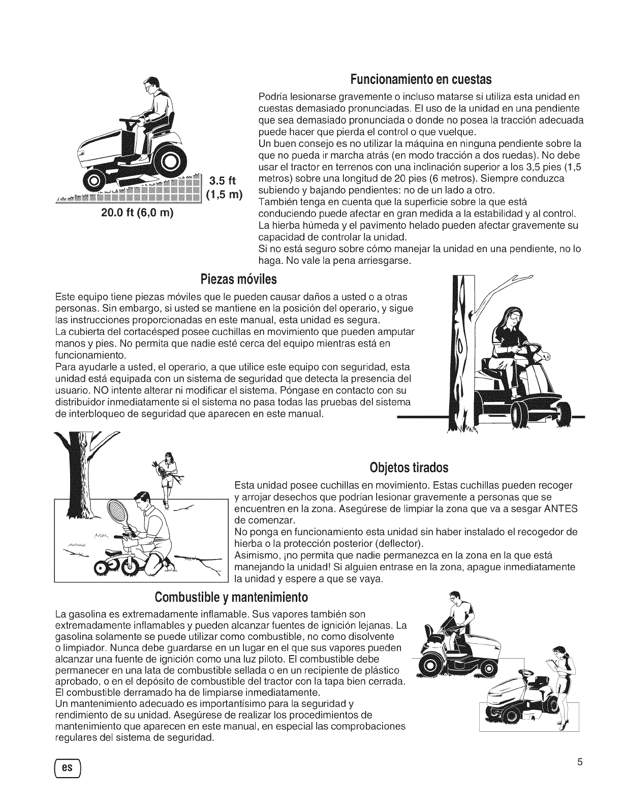
Funcionamientoencuestas
20.0 ft (6,0 rn)
Podria lesionarse gravemente o incluso matarse si utiliza esta unidad en
cuestas demasiado pronunciadas. El uso de la unidad en una pendiente
que sea demasiado pronunciada o donde no posea la traccion adecuada
puede hacer que pierda el control o que vuelque.
Un buen consejo es no utilizar la maquina en ninguna pendiente sobre la
que no pueda ir marcha atras (en modo traccion a dos ruedas). No debe
usar el tractor en terrenos con una inclinacion superior a los 3,5 pies (1,5
3.5 ft metros) sobre una Iongitud de 20 pies (6 metros). Siempre conduzca
(1,5 m) subiendo y bajando pendientes: no de un lado a otto.
Tambien tenga en cuenta que la superficie sobre la que esta
conduciendo puede afectar en gran medida a la estabilidad y al control.
La hierba humeda y el pavimento helado pueden afectar gravemente su
capacidad de controlar la unidad.
Si no esta seguro sobre como manejar la unidad en una pendiente, no Io
haga. No vale la pena arriesgarse.
Piezasmoviles
Este equipo tiene piezas moviles que le pueden causar da_os a usted o a otras
personas. Sin embargo, si usted se mantiene en la posicion del operario, y sigue
las instrucciones proporcionadas en este manual, esta unidad es segura.
La cubierta del cortacesped posee cuchillas en movimiento que pueden amputar
manos y pies. No permita que nadie este cerca del equipo mientras esta en
funcionamiento.
Para ayudarle a usted, el operario, a que utilice este equipo con seguridad, esta
unidad esta equipada con un sistema de seguridad que detecta la presencia del
usuario. NO intente alterar ni modificar el sistema. Pongase en contacto con su
distribuidor inmediatamente si el sistema no pasa todas las pruebas del sistema
de interbloqueo de seguridad que aparecen en este manual.
0bjetos tirados
Esta unidad posee cuchillas en movimiento. Estas cuchillas pueden recoger
y arrojar desechos que podrian lesionar gravemente a personas que se
encuentren en la zona. Asegurese de limpiar la zona que va a sesgar ANTES
de comenzar.
No ponga en funcionamiento esta unidad sin haber instalado el recogedor de
._........... hierba o la proteccion posterior (deflector).
"=_,- Asimismo, ino permita que nadie permanezca en la zona en la que esta
manejando la unidad! Si alguien entrase en la zona, apague inmediatamente
la unidad y espere a que se vaya.
Combustibleymantenimiento
La gasolina es extremadamente inflamable. Sus vapores tambien son
extremadamente inflamables y pueden alcanzar fuentes de ignicion lejanas. La
gasolina solamente se puede utilizar como combustible, no como disolvente
o limpiador. Nunca debe guardarse en un lugar en el que sus vapores pueden
alcanzar una fuente de ignicion como una luz piloto. El combustible debe
permanecer en una lata de combustible sellada o en un recipiente de plastico
aprobado, o en el deposito de combustible del tractor con la tapa bien cerrada.
El combustible derramado ha de limpiarse inmediatamente.
Un mantenimiento adecuado es importantisimo para la seguridad y
rendimiento de su unidad. Asegurese de realizar los procedimientos de
mantenimiento que aparecen en este manual, en especial las comprobaciones
regulares del sistema de seguridad.
5
Lea estas normas de seguridad y respetetas estrictamente. Et no respetar estas normas podria dar como resultado la
perdida det control de la unidad, lesiones personates graves o la muerte del usuario o de terceros que se encuentren
cerca, o podria causar da_os en la propiedad o en el equipo. La cubJerta del cortac_sped puede Ilegar a arnputar
manos y pies y lanzar objetos. En el texto, el tria_ngulo ,_ significa que debe seguir precauciones o advertencias
importantes.
FUNCIONAiVllENTO GENERAL
1. Debera_ leer, comprender y seguir todas las instrucciones que
se contienen en el manual o en la propia unidad antes de
empezar a utilizarla.
2. No coloque las manes o pies cerca de componentes giratorios
ni debajo de la ma_quina. Mantengase lejos en todo momento de
la apertura de descarga.
3. Unicamente adultos responsables que esten familiarizados
con las instrucciones debera_n hacer funcionar la unidad (la
normativa local puede imponer restricciones relativas a la edad
del operador).
4. Despeje la zona de objetos como son piedras, juguetes, cables,
etc. Esos objetos podrian ser cogidos y lanzados per la(s)
cuchilla(s).
5. Cerci6rese de que no hay personas en la zona de operaci6n
antes de empezar a utilizar la unidad. Detenga la unidad si
alguna persona entra en la zona de operaci6n.
6. Nunca Ileve en la unidad a nadie como pasajero.
7. No siegue en sentido contrario al normal a menos que no sea
absolutamente necesario. Mire siempre detr#_s y debajo antes
de desplazarse hacia atra_s y durante esa operaci6n.
8. No realice la descarga en ningt_n caso apuntando hacia una
persona en la operaci6n. No realice la descarga del material
contra una pared u otros elementos obstructivos. Los materiales
pueden rebotar hacia el usuario. Detenga la(s) cuchillas cuando
cruce sobre superficies con grava.
9. No haga funcionar la m#_quina sin que el recogedor de hierba,
la protecci6n posterior (deflector) y los dem#_s dispositivos de
seguridad esten en su lugar.
10. Reduzca antes de girar.
11. Nunca deje una unidad en funcionamiento sin vigilancia.
Siempre se deber#_ desacoplar el PTO, poner el freno de
estacionamiento, apagar el motor y retirar las Ilaves antes de
preceder a desmontar la unidad.
12. Desacople las cuchillas (PTO) cuando no vaya a utilizar la
unidad. Apague el motor y espere hasta la completa detenci6n
de todos los componentes antes de proceder a limpiar la
m#_quina, retirar el recogedor de hierba o desbloquear la
protecci6n posterior.
13. Utilice la ma_quina s61o con la luz del dia o con buena
iluminaci6n artificial.
14. No utilice la unidad mientras este bajo los efectos del alcohol o
de drogas.
15 Mantengase alerta ante el tra_fico cuando se halle cerca de vias
de comunicaci6n o cruce per elias.
16. Tenga especial cuidado cuando cargue o descargue la unidad
de remolques o camiones.
17. Utilice siempre protecciones oculares cuando utilice la unidad.
18. Los dates indican que los operadores de 60 aSos o ma_sesta_n
involucrados en gran parte de las lesiones relacionadas con
equipos motorizados. Estos operadores debera_n evaluar su
capacidad de operar el equipo de manera Io suficientemente
segura como para evitar lesiones, en ellos mismos o en
terceros.
19. Siga las recomendaciones del fabricante sobre los pesos y
contrapesos de las ruedas.
20. Tenga presente que el operador sra_el responsable de los
accidentes que puedan sufrir otras personas o propiedades.
21. Quienes conduzcan la unidad deber__n procurarse instrucci6n
pr#_ctica profesional.
22. Debera_n vestirse siempre calzado y pantalones robustos.
Nunca utilice la unidad con los pies desnudos o calzando
sandalias
23. antes de utilizar la unidad, siempre debera_ comprobar
visualmente que las cuchillas y los correspondientes
mecanismos esta_n en su sitio, intactos y bien firmes. Sustituya
los componentes gastados o daSados.
24. Desacople los elementos anexos antes de realizar las
siguientes acciones: Ilenar el dep6sito de combustible, retirar
elementos anexos o realizar ajustes (a menos que el ajuste o
ajustes puedan ser realizados desde la posici6n del operador).
25. AI estacionar, almacenar o dejar sin vigilancia la m__quina,
baje los elementos de corte, a menos que se utilice un cierre
meca_nico efectivo.
26. Antes de abandonar por cualquier causa la posici6n del
operador, ponga el freno de estacionamiento (si se dispone de
el), desacople el interruptor PTO, detenga el motor y saque la
Ilave.
27. Para reducir el riesgo de incendio, mantenga la unidad libre de
hierba, hojas o exceso de lubricantes. No detenga ni estacione
la unidad sobre hojas o hierba secas, ni sobre materiales
combustibles.
TRANSPORTE YALMACENAMIENTO
1. Cuando transporte la unidad sobre un remolque abierto,
cerci6rese de esta_orientado hacia adelante, en la direcci6n del
viaje. Si la unidad est,_ orientada en el sentido contrario al de
marcha, el empuje del viento podria daSarla.
2. Siga siempre pr#_cticas seguras de repostaje y manipulaci6n
de combustible al cargar combustible en la unidad despues del
transporte o almacenaje.
3. No almacene la unidad (con combustible) en lugares cerrados
de pobre ventilaci6n. Los vapores del combustible pueden
Ilegar hasta una fuente de ignici6n (hornos, calentadores de
agua, etc.) y producir una explosi6n. El vapor del combustible
tambien es t6xico para los humanos y los animales.
4. Siempre siga las instrucciones de manual del motor para
preparaciones para almacenaje, antes de almacenar la unidad,
tanto para periodos cortes como largos.
5. Siempre siga las instrucciones del manual de motor para
procedimientos adecuados de arranque al colocar la unidad
nuevamente en servicio.
6. No almacene nunca la unidad o el dep6sito de combustible
en el interior de lugares en que haya llamas expuestas o luces
piloto, como es el caso de un calentador de agua. Deje que la
unidad se enfrie antes de proceder a su almacenamiento.
FUNCIONAMIENTO EN PENDIENTES
Las pendientes son un factor de gran p@dida en los casos de p@dida de
control yen los accidentes en los que vuelca el cortacesped, que pueden
resultar en lesiones graves o incluso la muerte. La operaci6n en todo tipo
de pendientes requiere una precauc_on a_adida. Si no puede ir hacia
atra_ssobre una pendiente con el cortacesped o no se siente seguro
sobre la pendiente, no la utilice la unidad sobre ella.
El control de un tractor cortacesped que se deslice sobre una
pendiente no se recuperara_ mediante la aplicaci6n del freno. Las
principales causas de p@dida del control son: insuficiente agarre de
los neum__ticos sobre el firme, el exceso de velocidad, la aplicaci6n
incorrecta del freno, la inadecuaci6n del ma_quina para el uso concreto,
la incorrecta percepci6n de la condiciones del piso, o el engache o la
distribuci6n de cargas incorrectos.
1. Accione el cortacesped en pendientes, en subida y bajada y no
a Io ancho.
2. Preste atenci6n ante posibles hoyos, surcos o golpes. El
terreno irregular podria hacer que la unidad vuelque. H6gt gr__s
kan g6mma hinder.
3. Escoja una velocidad de segado que le permita no tener que
detenerse o cambiar la velociad mientras este recorriendo la
pendiente.
4. No utilice el cortacesped sobre hierba h0meda. Los neuma_ticos
podrian perder tracci6n.
5. Siempre mantenga la unidad con una marcha al bajar
las pendientes. No ponga el punto muerto para bajar por
pendientes.
6. Evite arrancar, detenerse, o girar sobre las pendientes. Si los
neuma_ticos pierden tracci6n, desacople las cuchillas y contin0e
lentamente en linea recta hacia abajo.
7. Todo desplazamiento en pendientes debera_ ser lento y gradual.
No realice cambios repentinos en la velocidad o en la direcci6n;
la ma_quina podria volcar.
8. Ponga la mayor atenci6n cuando haga funcionar la ma_quina
con recogedores de hierba u otros elementos acoplados;
pueden afectar a la estabilidad de la unidad. No utilice la
ma_quina en pendientes pronunciadas.
9. No intente estabilizar la ma_quina colocando su pie sobre el piso
(en unidades en las que el conductor va montado sobre elias).
10. No utilice el cortacesped cerca bajadas, zanjas o terraplenes. El
cortacesped podria volcar si una rueda se sit0a sobre el borde
de una zanja o risco, o si el borde cede.
11. No utilice recogedores de hierba en pendientes pronunciadas.
12. No realice la operaci6n de segado en pendientes si no puede ir
marcha atra_ssobre elias.
13. Consulte a su concesionario/vendedor autorizado para obtener
recomendaciones sobre pesos y contrapesos para las ruedas
para mejorar la estabilidad.
14. Retire obst__culos como son piedras, ramas de __rboles, etc.
15. Opere a bajas velocidades. Los neum__ticos pueden perder
tracci6n en pendientes incluso si los frenos funcionan
adecuadamente.
16. No realice giros en pendientes a menos que ello sea necesario,
y, en ese case, haga giros lentos y graduales, siempre
pendiente abajo si ello es posible.
17. Modelos con tracci6n alas cuatro ruedas: La tracci6n alas
cuatro ruedas mejora el acceso a terrenos con pendientes
peligrosas que aumenta la posibilidad de vuelco. Si la m__quina
se detiene mientras sube una pendiente, detenga las cuchillas
y retroceda lentamente. Evite realizar giros repentinos.
EQUIPO REMOLCADO (UNIDADES
MONTABLES)
1. Remolque solamente con una ma_quina que tenga un
enganche dise_ado para remolque. No sujete el equipo
remolcado a elementos que no sean el punto de enganche.
2. Siga las recomendaciones del fabricante en cuanto a los limites de
peso para equipos remolcados y remolque en pendientes.
3. No permita que que ni_os u otras personas se suban al equipo
remolcado.
4. Sobre las pendientes, el peso del equipo remolcado puede
causar p@dida de tracci6n y p@dida de control.
5. Vaya despacio y deje una distancia extra para poder parar.
6. No ponga el punto muerto para bajar por pendientes.
ADVERTENCIA
Nunca opere en pendientes de ma_sde117,6% (10°); esos
vatores equivalen a un incremento vertical de 106 cm (3-1/2
pies) en un espacio horizontal de 607 cm (20 pies).
Cuando opere en pendientes utilice pesos y contrapesos
adicionales para las ruedas. Consulte a su concesionario/
vendedor para determinar que pesos apropiados se
encuentran disponibles para su unidad.
Seteccione una velocidad de avance lenta antes de
empezar a subir una pendiente. Adema_sde los pesos
delanteros, debe emplearse una precaucion especial
at operar en pendientes con recogedores de hierba de
enganche posterior.
Corte el cesped SUBIENDO y BAJANDO pendientes,
nunca de un costado a otro, ponga la mayor atencion
cuando cambie la direccion y NO ARRANQUE NI SE
DETENGA EN PENDIENTES.
N QOS
Tragiska olyckor kan intr__ffaom anv__ndaren inte __ruppm__rksam p__
n__rvaron av barn. Los niSos suelen sentirse atraidos por la unidad y
por la actividad del cortacesped. Nunca de por supuesto que los niSos
se quedara_n en el lugar donde los vie per 01tima vez.
1. Mantenga a los niSos fuera del Area de corte y bajo la vigilancia
atenta de otro adulto responsable.
2. Este atento y apague el equipo si entran niSos en la zona.
3. Antes y durante el avance marcha atra_s, mire atra_s y hacia
abajo para detectar la presencia de niSos.
4. Nunca Ileve niSos en la unidad, ni siquiera sin la(s) cuchilla(s).
Los niSos podrian caerse y lesionarse gravemente, o interferir
en el seguro funcionamiento de la unidad. Los niSos que
hayan montado en un cortacesped en otros momentos pueden
aparecer repentinamente en la zona en la que este cortando el
cesped para que los Ileve y pueden caerse o ser atropellados
por la ma_quina.
5. Nunca permita que niSos hagan funcionar la unidad.
6. Tenga un especial cuidado al acercarse a esquinas ciegas,
arbustos, __rboles u otros objetos que puedan dificultar la visi6n.
EiVllSIONES
1. El humo del motor de este producto contiene agentes quimicos
que se sabe que, en ciertas cantidades, pueden causar ca_ncer,
malformaciones congenitas u otros perjuicios relacionados con
la salud reproductiva.
2. Busque informac.i6n relevante de Periodo de Permanencia de
las Emisiones eIndice en el Aire en la etiqueta sobre emisiones
del motor.
SISTEMA DE IGNIClON
1. Este sistema de encendido por chispa cumple con la norma
ICEA-002 canadiense.
7

REPARACION Y MANTENIMIENTO
S_ker hantering av bensin
1. Apague todos los cigarrillos, puros, pipas y cualquier otra fuente
de ignici6n.
2. Utilice t_nicamente contenedores de gasolina homologados.
3. No retire la tapa de la gasolina ni reponga combustible con el
motor en funcionamiento. LAt motorn svalna innan den fylls pA.
4. No Ilene el dep6sito de la mAquina en espacios cerrados.
5. No guarde la mAquina ni el contenedor de carburante en
lugares en los en que haya llamas expuestas, se produzcan
chispas o haya luces pilotos, como es el caso calentadores de
agua u otros dispositivos.
6. Nunca Ilene recipientes dentro de un vehiculo o sobre el piso
de un cami6n o remolque con cobertores de pl#_stico. Siempre
coloque los contenedores sobre el suelo, lejos del vehiculo,
antes de proceder a Ilenarlos.
7. Retire del remolque o cami6n el equipamiento alimentado pot
gasolina y reponga el carburante sobre el suelo. Si ello no es
posible, entonces abastezca el vehiculo sobre un remolque
con un contenedor port__til, no con una boquilla de surtidor de
gasolina.
8. Mantenga la boquilla en contacto con el borde de la apertura
del tanque o recipiente de combustible en todo momento y
hasta haber completado la operaci6n de Ilenado. No utilice
dispositivos para bloquear y mantener abiertas boquillas.
9. Byt klAder omgAende om du spillt br__nsle pA klAderna.
10. En ningQn caso deberA superar el limite de Ilenado del dep6sito
de combustible. Vuelva a colocar la tapa del dep6sito y ajQstela
firmemente.
11. Emplee la mayor precauci6n cuando manipule gasolina u otros
elementos combustibles. Los carburantes son infiamables y sus
vapores, explosivos.
12. Si se derrama combustible, no intente poner el motor en
marcha; aleje la maquina del area del derrame y evite cualquier
fuente de ignici6n hasta que se hayan disipado los vapores del
combustible.
13. Vuelva ajustar firmemente las tapas de los tanques y de los
contenedores de combustible.
Servicio tecnico y mantenimiento
1. Nunca haga funcionar la unidad en espacios cerrados en los
que puedan acumularse el mon6xido de carbono.
2. Mantenga las tuercas y pernos, especialmente los pernos de
acomple de las cuchillas, apretados y mantenga el equipo en
buenas condiciones.
3. Nunca fuerce los dispositivos de seguridad. Verifique
peri6dicamente su correcto funcionamiento, y realice todas las
reparaciones necesarias si no funcionan correctamente.
4. Mantenga la unidad libre de hierba, hojas u otras
acumulaciones de desechos. Limpie posibles derrames de
lubricantes o combustible y retire los desechos que puedan
resultar impregnados de combustible. Deje que la m__quina se
enfrie antes de proceder a su almacenamiento.
5. Si golpea cualquier objeto con la unidad, detengase e
inspeccione la m__quina. Antes de volver a hacer funcionar la
m__quina, realice las reparaciones necesarias.
6. No realice ningt_n tipo de ajustes o reparaciones con el motor
en marcha.
7. Supervise con frecuencia los componentes de los recogedores
de hierba y la protecci6n posterior y, cuando sea necesario,
sustitQyalos por componentes recomendados por el fabricante.
8. Las cuchillas del cortacesped son elementos cortantes.
Retraiga la cuchilla o utilice guantes y emplee la mayor
precauci6n cuando realice operaciones de mantenimiento en
elias.
9. Verifique con frecuencia el funcionamiento de los frenos. Haga
los ajustes y reparaciones necesarios.
10. Mantenga o rcambie las etiquetas de instrucciones y de
seguridad cuando sea necesario.
11. No retire el filtro de gasolina mientras el motor este caliente; la
gasolina que se derrame podria incendiarse. No disperse las
abrazaderas del tubo de combustible mas alia de Io necesario.
Asegure firmemente las tuercas de agarre de las abrazaderas
sobre el filtro tras su instalaci6n.
12. No utilice gasolina que METANOL, gasohol que contenga mas
de110% de ETANOL, aditivos para la gasolina, o white gas; el
motor o el sistema de alimentaci6n podrian resultar dafiados.
13. Si el dep6sito de combustible ha de ser drenado, esa operaci6n
debe realizarse al aire libre.
14. Reemplace los silenciadores/tapabocas defectuosos.
15. Mantenga o rcambie las etiquetas de instrucciones y de
seguridad cuando sea necesario.
16. Solo use piezas de reposici6n autorizadas por la f__brica al
hacer reparaciones.
17. Cumpla siempre con las especificaciones de f__brica en todas
las configuraciones y ajustes.
18. Unicamente se deberan utilizar establecimientos autorizados
para el mantenimiento y las reparaciones de mayor calado.
19. Nunca intente realizar reparaciones mayores en esta unidad a
no ser que tenga la capacitaci6n necesaria. Procedimientos de
reparaci6n incorrectos pueden resultar en un funcionamiento
con riesgos, dafios en el equipo y la anulaci6n de la garantia del
fabricante.
20. En m__quinas de cortacespedes de mQltiples cuchillas, debera
emplear la mayor precauci6n, ya que una cuhilla puede hacer
girar a las demas.
21. No cambie los ajustes del limitador del motor ni revolucione
en exceso el motor. La operaci6n de un motor a una velocidad
excesiva puede incrementar el riesgo de que se produzcan
lesiones personales.
22. Desenganche la transmisi6n de los accesorios, detenga
el motor, retire la Ilave y desconecte el o los cables de la
bujia antes de realizar las siguientes operaciones: despejar
obstrucciones y conductos, realizar reparaciones, tras golpear
con un objeto o si la unidad vibra anormalmente. Tras golpear
un objeto, inspeccione la m__quina en busca de posibles dafios
y haga las reparaciones necesarias antes de volver a poner en
marcha y hacer funcionar el equipo.
23. No coloque nunca las manos cerca de componentes m6viles,
como son el ventilador de refrigeraci6n de la bomba de
carburante cuando la unidad este en funcionamiento (los
ventiladores de refrigeraci6n de la bomba de carburante est__n
situadas tipicamente en la parte superior del conjunto motriz).
24. Unidades de con bombas hidraulicas, mangueras o motores:
VARNING: Los fluidos hidraulicos que escapen a presi6n puede
tener fuerza suficientes para penetrar la piel y causar lesiones
graves. Se se inyectan fiuidos extrafios en la piel, deberan
ser eliminados quirt_rgicamente en el plazo maximo de unas
horas por un facultativo que este familiarizado con esta forma
de lesiones; en caso contrario podria producirse un cuadro de
gangrena. Mantenga el cuerpo y las manos lejos de orificios
o boquillas de los que salgan eyectados fiuidos hidraulicos a
alta presi6n. Utilice papel o cart6n, no las manos, para detectar
fugas. Cerci6rese de que todas las conexiones de los fiuidos
hidraulicos est__n ajustadas y que todas las mangueras y cables
se hayan en buenas condiciones antes de aplicar presi6n
sobre el sistema. Si se producen fugas, haga que la unidad
sea reparada de forma inmediata por su centro de distribuci6n
autorizado.
25. VARNING: Dispositivo acumulador de energia. La inadecuada
liberaci6n de resortes puede resultar en graves lesiones
corporales. Los resortes deben ser retirados por un tecnico
autorizado.
26. Modelos que incluyen un radiador de motor: VARNING:
Dispositivo acumulador de energia. Para evitar lesiones
corporales graves a raiz de la explosi6n del anticongelante
o vapor caliente, nunca intente retirar la tapa del radiador
mientras que el motor este en marcha. Detenga el motor y
espere a que se enfrie. Incluso despues, tenga extremo cuidado
al retirar la tapa.
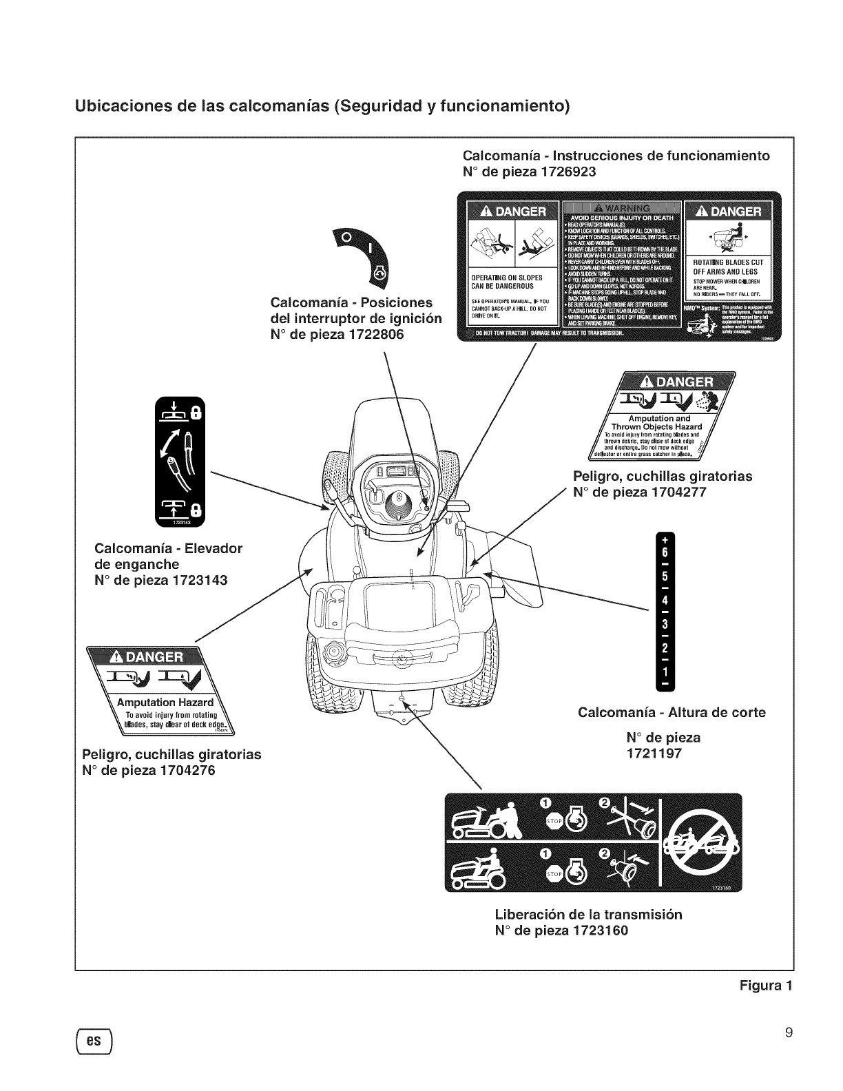
Ubicaciones de las calcomanias (Seguridad y funcionamiento)
Caicomania =Instrucciones de funcionamiento
N° de pieza 1726923
Calcomania - Posiciones
del interruptor de ignicion
N° de pieza 1722806
Peligro, cuchillas giratorias
N° de pieza 1704277
Calcomania - Elevador
de enganche
N° de pieza 1723143
\\Amputation Hazard
\\ To avoid injury from rotating \\
%bhd0a, afay=0a,0,d00,0,_\\
Peligro, cuchiiias giratorias
N° de pieza 1704276
Caicomania -Aitura de corte
N° de pieza
1721197
Liberacion de ia transmision
N° de pieza 1723160
Figura
9
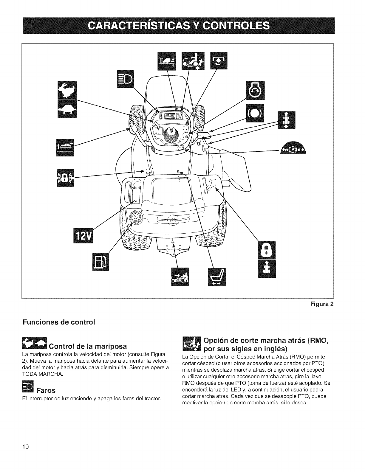
Figura2
Funciones de control
Control de la mariposa
La mariposa controla la velocidad det motor (consutte Figura
2). Mueva la mariposa hacia delante para aumentar la veloci-
dad det motor y hacia atr,_s para disminuirla. Siempre opere a
TODA MARCHA.
Faros
El interruptor de luz enciende y apaga los faros del tractor.
Opcion de corte marcha atras (RIVIO,
por sus siglas en ingles)
La Opcion de Cortar et Cesped Marcha Atras (RMO) permite
cortar cesped (o usar otros accesorios accionados por PTO)
mientras se desplaza marcha atra_s.Si elige cortar el cesped
o utilizar cualquier otro accesorio marcha atra_s,gire la Itave
RMO despues de que PTO (toma de fuerza) este acoplado. Se
encendera_ la luz det LED y, a continuacion, et usuario podra_
cortar marcha atra_s.Cada vez que se desacople PTO, puede
reactivar la opcion de corte marcha atra_s,si Io desea.
10
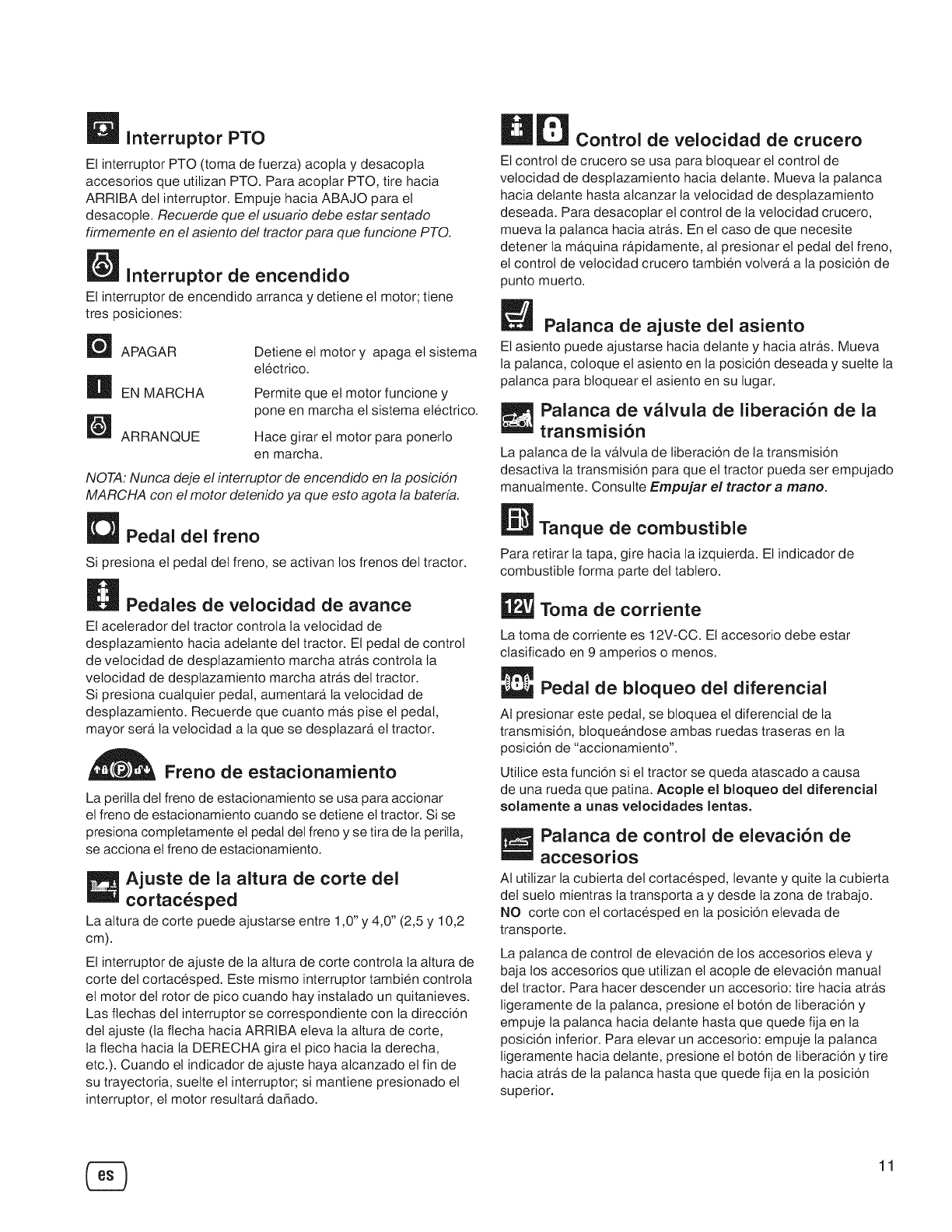
_ Interruptor PTO
Et interruptor PTO (toma de fuerza) acopta y desacopta
accesorios que utilizan PTO. Para acoplar PTO, tire hacia
ARRIBA del interruptor. Empuje hacia ABAJO para el
desacople. Recuerde que el usuario debe estar sentado
firmemente en el asiento de! tractor para que funcione PTO.
Interruptor de encendido
El interruptor de encendido arranca y detiene el motor; tiene
tres posiciones:
_ APAGAR
H EN MARCHA
ARRANQUE
Detiene el motor y apaga el sistema
electrico.
Permite que et motor funcione y
pone en marcha el sistema etectrico.
Hace girar el motor para ponerlo
en marcha.
NOTA: Nunca deje el interruptor de encendido en la posicion
MARCHA con el motor detenido ya que esto agota la bateria.
Pedal dei freno
Si presiona el pedal del freno, se activan los frenos del tractor.
_Pedales de velocidad de avance
El aceterador del tractor controta la vetocidad de
desptazamiento hacia adetante det tractor. Et pedal de control
de velocidad de desptazamiento marcha atra_scontrola la
vetocidad de desplazamiento marcha atra_sdel tractor.
Si presiona cuatquier pedal, aumentara_ la velocidad de
desptazamiento. Recuerde que cuanto ma_spise et pedal,
mayor sera_la velocidad a la que se desplazara_ el tractor.
Freno de estacionamiento
La perilta det freno de estacionamiento se usa para accionar
el freno de estacionamiento cuando se detiene el tractor. Si se
presiona completamente el pedal del freno y se tira de la peritla,
se acciona et freno de estacionamiento.
Ajuste de la altura de corte del
cortacesped
La attura de corte puede ajustarse entre 1,0"y 4,0" (2,5 y 10,2
cm).
El interruptor de ajuste de la altura de corte controla la attura de
corte det cortacesped. Este mismo interruptor tambien controla
et motor del rotor de pico cuando hay instatado un quitanieves.
Las fiechas det interruptor se correspondiente con la direccion
det ajuste (la fiecha hacia ARRIBA eleva la altura de corte,
la fiecha hacia la DERECHA gira el pico hacia la derecha,
etc.). Cuando et indicador de ajuste haya alcanzado el fin de
su trayectoria, suelte el interruptor; si mantiene presionado el
interruptor, el motor resultara_ da_ado.
Control de velocidad de crucero
El control de crucero se usa para btoquear el control de
vetocidad de desplazamiento hacia detante. Mueva la patanca
hacia delante hasta alcanzar la velocidad de desplazamiento
deseada. Para desacoptar el control de la velocidad crucero,
mueva la patanca hacia atra_s.En el caso de que necesite
detener la ma_quinara_pidamente, at presionar el pedal det freno,
el control de velocidad crucero tambien volvera_ a la posicion de
punto muerto.
Palanca de ajuste del asiento
El asiento puede ajustarse hacia delante y hacia atra_s.Mueva
la palanca, coloque el asiento en la posicion deseada y suelte la
patanca para bloquear el asiento en su lugar.
Palanca de valvula de liberaci6n de la
transmisi6n
La palanca de la va_lvulade liberacion de la transmision
desactiva la transmision para que el tractor pueda ser empujado
manualmente. Consulte Empujar el tractor a mano.
Tanque de combustible
Para retirar la tapa, gire hacia la izquierda. El indicador de
combustible forma parte del tablero.
Toma de corriente
La toma de corriente es 12V-CC. El accesorio debe estar
clasificado en 9 amperios o menos.
Pedal de bloqueo del diferencial
At presionar este pedal, se bloquea el diferencial de la
transmision, btoquea_ndose ambas ruedas traseras en la
posicion de "accionamiento'.
Utilice esta funcion si el tractor se queda atascado a causa
de una rueda que patina. Acople el bloqueo del diferencial
solarnente aunas velocidades lentas.
Palanca de control de elevaci6n de
accesorios
AI utilizar la cubierta del cortacesped, levante y quite la cubierta
del suelo mientras la transporta a y desde la zona de trabajo.
NO corte con el cortacesped en la posicion elevada de
transporte.
La palanca de control de elevacion de los accesorios eleva y
baja los accesorios que utilizan et acopte de elevacion manual
del tractor. Para hacer descender un accesorio: tire hacia atra_s
ligeramente de la patanca, presione el boton de liberacion y
empuje la palanca hacia delante hasta que quede fija en la
posicion inferior. Para elevar un accesorio: empuje la patanca
ligeramente hacia detante, presione et boton de liberacion y tire
hacia atra_sde la palanca hasta que quede fija en la posicion
superior.
11
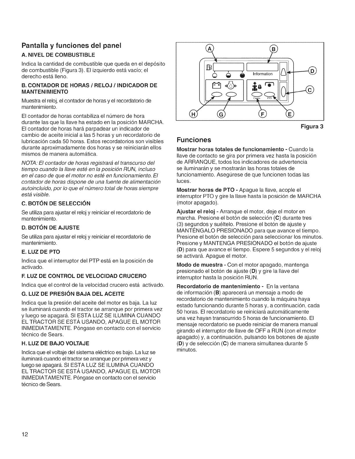
Pantalla y funciones del panel
A. NIVEL DE COMBUSTIBLE
Indica la cantidad de combustible que queda en el dep6sito
de combustible (Figura 3). El izquierdo ester vacio; el
derecho ester Ileno.
B. CONTADOR DE HORAS /RELOJ /INDICADOR DE
MANTENIMiENTO
Muestra el reloj, el contador de horas y el recordatorio de
mantenimiento.
El contador de horas contabiliza el numero de hora
durante las que la Ilave ha estado en la posici6n MARCHA.
El contador de horas hara. parpadear un indicador de
cambio de aceite inicial alas 5 horas y un recordatorio de
lubricaci6n cada 50 horas. Estos recordatorios son visibles
durante aproximadamente dos horas y se reiniciar_m ellos
mismos de manera autom_ttica.
NOTA: El contador de horas registrara el transcurso del
tiempo cuando la Ilave este en la posicidn RUN, incluso
en el caso de que el motor no este en funcionamiento. El
contador de horas dispone de una fuente de alimentacidn
autoincluido, por Io que el n#mero total de horas siempre
esta visible.
C. BOTON DE SELECCION
Se utiliza para ajustar el reloj y reiniciar el recordatorio de
mantenimiento.
D. BOT(DN DE AJUSTE
Se utiliza para ajustar el reloj y reiniciar el recordatorio de
mantenimiento.
E. LUZ DE PTO
Indica que el interruptor del PTP ester en la posici6n de
activado.
RLUZ DE CONTROL DE VELOCIDAD CRUCERO
Indica que el control de la velocidad crucero ester activado.
G. LUZ DE PRESI()N BAJA DEL ACEiTE
Indica que la presi6n del aceite del motor es baja. La luz
se iluminara cuando el tractor se arranque por primera vez
y luego se apagarb.. SI ESTA LUZ SE ILUMINA CUANDO
EL TRACTOR SE EST', USANDO, APAGUE EL MOTOR
INMEDIATAMENTE. P6ngase en contacto con el servicio
tecnico de Sears.
H. LUZ DE BAJO VOLTAJE
Indica que el voltaje del sistema electrico es bajo. La luz se
iluminar_t cuando el tractor se arranque por primera vez y
luego se apagar& Sl ESTA LUZ SE ILUMINA CUANDO
EL TRACTOR SE EST', USANDO, APAGUE EL MOTOR
INMEDIATAMENTE. P6ngase en contacto con el servicio
tecnico de Sears.
Figura 3
Funciones
Mostrar horas totales de funcionamiento - Cuando la
Ilave de contacto se gira por primera vez hasta la posici6n
de ARRANQUE, todos los indicadores de advertencia
se iluminar_m y se mostrar_tn las horas totales de
funcionamiento. Asegt]rese de que funcionen todas las
luces.
Mostrar horas de PTO - Apague la Ilave, acople el
interruptor PTO y gire la Ilave hasta la posici6n de MARCHA
(motor apagado).
Ajustar el reloj - Arranque el motor, deje el motor en
marcha. Presione el bot6n de selecci6n (C) durante tres
(3) segundos y sueltelo. Presione el bot6n de ajuste y
MANTENGALO PRESIONADO para que avarice el tiempo.
Presione el bot6n de selecci6n para seleccionar los minutos.
Presione y MANTENGA PRESIONADO el bot6n de ajuste
(D) para que avarice el tiempo. Espere 5 segundos y el reloj
se activar_t. Apague el motor.
Modo de muestra - Con el motor apagado, mantenga
presionado el bot6n de ajuste (D) y gire la Ilave del
interruptor hasta la posici6n RUN.
Recordatorio de mantenimiento - En la ventana
de informaci6n (B) aparecer_t un mensaje a modo de
recordatorio de mantenimiento cuando la m_tquina haya
estado funcionando durante 5 horas y, a continuaci6n, cada
50 horas. El recordatorio se reiniciar_t automa.ticamente
una vez hayan transcurrido 5 horas de funcionamiento. El
mensaje recordatorio se puede reiniciar de manera manual
girando el interruptor de Ilave de OFF a RUN (con el motor
apagado) y, a continuaci6n, pulsando los botones de ajuste
(D) y de selecci6n (C) de manera simultanea durante 5
minutos.
12
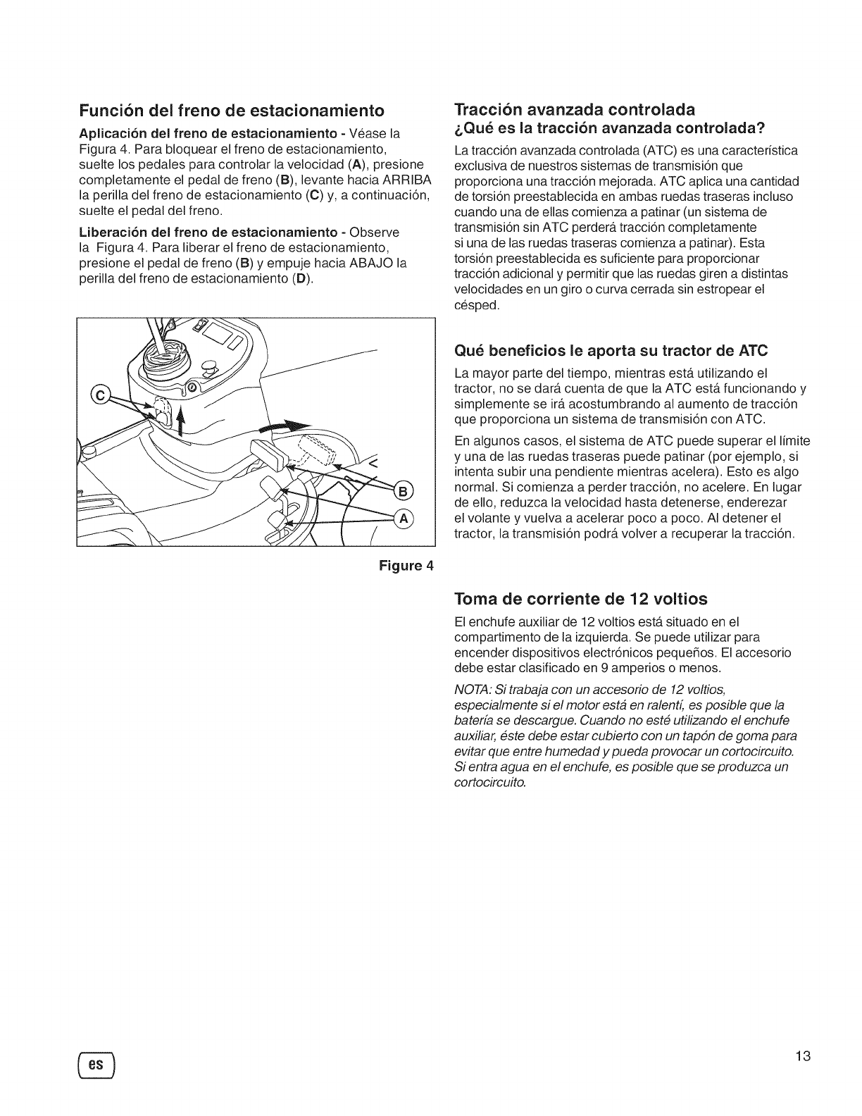
Funcion del freno de estacionamiento
Aplicaci6n del freno de estacionamiento - Vease la
Figura 4. Para bloquear el freno de estacionamiento,
suelte los pedales para controlar la velocidad (A), presione
completamente el pedal de freno (B), levante hacia ARRIBA
la perilla del freno de estacionamiento (C) y, a continuaci6n,
suelte el pedal del freno.
Liberaci6n del freno de estacionamiento - Observe
la Figura 4. Para liberar el freno de estacionamiento,
presione el pedal de freno (B) y empuje hacia ABAJO la
perilla del freno de estacionamiento (D).
Traccion avanzada controlada
&Que es la traccion avanzada controlada?
La tracci6n avanzada controlada (ATC) es una caracteristica
exclusiva de nuestros sistemas de transmisi6n que
proporciona una tracci6n mejorada. ATC aplica una cantidad
de torsi6n preestablecida en ambas ruedas traseras incluso
cuando una de elias comienza a patinar (un sistema de
transmisi6n sin ATC perdera, tracci6n completamente
si una de las ruedas traseras comienza a patinar). Esta
torsi6n preestablecida es suficiente para proporcionar
tracci6n adicional y permitir que las ruedas giren a distintas
velocidades en un giro o curva cerrada sin estropear el
cesped.
Figure 4
Que beneficios le aporta su tractor de ATC
La mayor parte del tiempo, mientras esta. utilizando el
tractor, no se data cuenta de que la ATC esta. funcionando y
simplemente se ira.acostumbrando al aumento de tracci6n
que proporciona un sistema de transmisi6n con ATC.
En algunos casos, el sistema de ATC puede superar el limite
y una de las ruedas traseras puede patinar (por ejemplo, si
intenta subir una pendiente mientras acelera). Esto es algo
normal. Si comienza a perder tracci6n, no acelere. En lugar
de ello, reduzca la velocidad hasta detenerse, enderezar
el volante y vuelva a acelerar poco a poco. AI detener el
tractor, la transmisi6n podra volver a recuperar la tracci6n.
Toma de corriente de 12 voltios
El enchufe auxiliar de 12 voltios estersituado en el
compartimento de la izquierda. Se puede utilizar para
encender dispositivos electr6nicos pequeSos. El accesorio
debe estar clasificado en 9 amperios o menos.
NOTA: Si trabaja con un accesorio de 12 voltios,
especialmente si el motor esta en ralent4 es posible que la
bateria se descargue. Cuando no este utilizando el enchufe
auxiliar, este debe estar cubierto con un tapdn de goma para
evitar que entre humedad y pueda provocar un cortocircuito.
Si entra agua en el enchufe, es posible que se produzca un
cortocircuito.
13
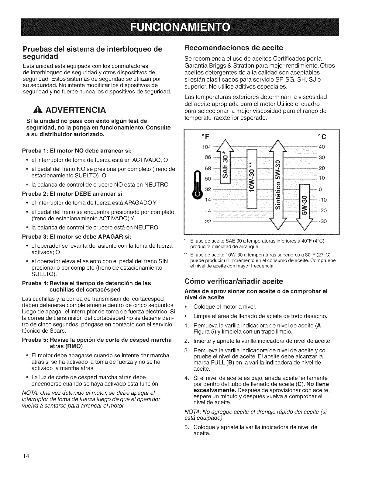
Pruebas del sistema de interbloqueo de
seguridad
Esta unidad estA equipada con los conmutadores
de interbloqueo de seguridad y otros dispositivos de
seguridad. Estos sistemas de seguridad se utilizan por
su seguridad. No intente modificar los dispositivos de
seguridad y no fuerce nunca los dispositivos de seguridad.
ADVERTENCIA
Si la unidad no pasa con 6xito alg_n test de
seguridad, no la ponga en funcionamiento. Consulte
a su distribuidor autorizado.
Prueba 1 : El motor NO debe arrancar si:
= el interruptor de toma de fuerza esta en ACTIVADO, O
= el pedal del freno NO se presiona por completo (freno de
estacionamiento SUELTO), O
= la palanca de control de crucero NO esta en NEUTRO.
Prueba 2: El motor DEBE arrancar si:
= el interruptor de toma de fuerza estA APAGADO Y
= el pedal del freno se encuentra presionado por completo
(freno de estacionamiento ACTIVADO) Y
• la palanca de control de crucero esta en NEUTRO.
Prueba 3: El motor se debe APAGAR si:
= el operador se levanta del asiento con la toma de fuerza
activada; O
= el operador eleva el asiento con el pedal del freno SiN
presionarlo por completo (freno de estacionamiento
SUELTO).
Prueba 4: Revise el tiempo de detenci6n de las
cuchillas del cortac6sped
Las cuchillas y la correa de transmisi6n del cortacesped
deben detenerse completamente dentro de cinco segundos
luego de apagar el interruptor de toma de fuerza electrico. Si
la correa de transmisi6n del cortacesped no se detiene den-
tro de cinco segundos, p6ngase en contacto con el servicio
t6cnico de Sears.
Prueba 5: Revise la opci6n de eorte de e6sped marcha
atras (RMO)
= El motor debe apagarse cuando se intente dar marcha
atrAs si se ha activado la toma de fuerza y no se ha
activado la marcha atrAs.
= La luz de corte de cesped marcha atrAs debe
encenderse cuando se haya activado esta funci6n.
NOTA: Una vez detenido el motor, se debe apagar el
interruptor de toma de fuerza luego de que el operador
vuelva a sentarse para arrancar el motor.
Recomendaciones de aceite
Se recomienda el uso de aceites Certificados por la
Garantia Briggs & Stratton para mejor rendimiento. Otros
aceites detergentes de alta calidad son aceptables
si estan clasificados para servicio SF, SG, SH, SJ o
superior. No utilice aditivos especiales.
Las temperaturas exteriores determinan la viscosidad
del aceite apropiada para el motor.Utilice el cuadro
para seleccionar la mejor viscosidad para el rango de
temperatu-raexterior esperado.
oF
104
86
68
5O
32
i4
-4
°22
°C
El uso de aceite SAE 30 a temperaturas inferiores a 40°F (4°C)
producira dificultad de arranque.
** El uso de aceite 10W-30 a temperaturas superiores a 80°F (27°C)
puede producir un incremento en el consumo de aceite. Compruebe
el nivel de aceite con mayor frecuencia.
C6mo verificada_adir aceite
Antes de aprovisionar con aceite o de comprobar el
nivel de aceite
= Coloque el motor a nivel.
Limpie el Area de Ilenado de aceite de todo desecho.
1. Remueva la varilla indicadora de nivel de aceite (A,
Figura 5) y limpiela con un trapo limpio.
2. Inserte y apriete la varilla indicadora de nivel de aceite.
3. Remueva la varilla indicadora de nivel de aceite y co
pruebe el nivel de aceite. El aceite debe alcanzar la
marca FULL (B) en la varilla indicadora de nivel de
aceite.
4, Si el nivel de aceite es bajo, a_ada aceite lentamente
por dentro del tubo de Ilenado de aceite (C). No Ilene
excesivamente. Despues de aprovisionar con aceite,
espere un minuto y despues vuelva a comprobar el
nivel de aceite.
NOTA: No agregue aceite al drenaje rapido de! aceite (si
esta equipado).
5. Coloque y apriete la varilla indicadora de nivel de
aceite.
14
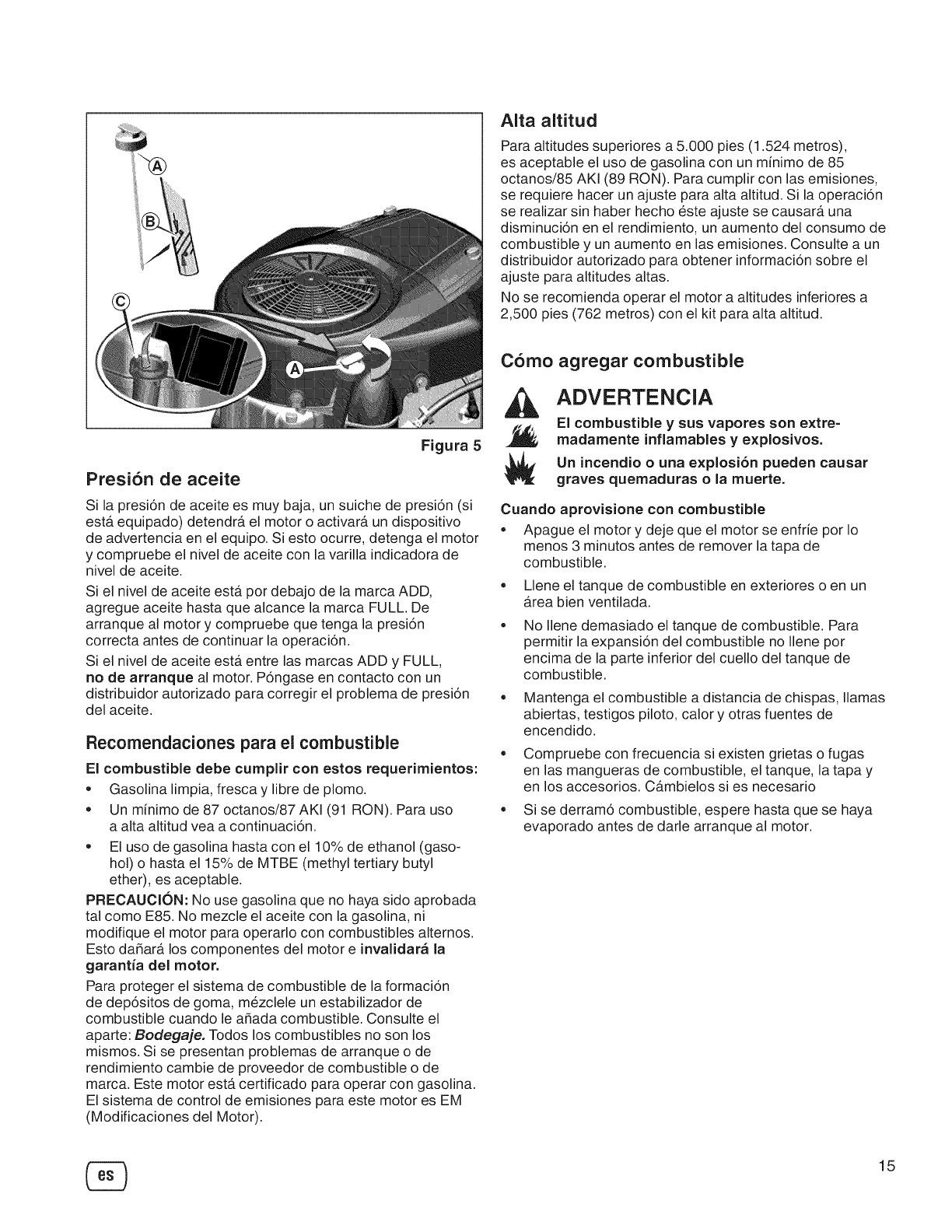
Presion de aceite
Figura 5
Si la presi6n de aceite es muy baja, un suiche de presi6n (si
esta equipado) detendra el motor o activara, un dispositivo
de advertencia en el equipo. Si esto ocurre, detenga el motor
y compruebe el nivel de aceite con la varilla indicadora de
nivel de aceite.
Si el nivel de aceite esta por debajo de la marca ADD, =
agregue aceite hasta que alcance la marca FULL. De
arranque al motor y compruebe que tenga la presi6n =
correcta antes de continuar la operaci6n.
Si el nivel de aceite esta entre las marcas ADD y FULL,
no de arranque al motor. P6ngase en contacto con un
distribuidor autorizado para corregir el problema de presi6n =
del aceite.
Recomendaciones para el combustible
El combustible debe cumplir con estos requerimientos:
= Gasolina limpia, fresca y libre de plomo.
= Un minimo de 87 octanos/87 AKI (91 RON). Para uso
a alta altitud vea a continuaci6n.
= El uso de gasolina hasta con el 10% de ethanol (gaso-
hol) o hasta el 15% de MTBE (methyl tertiary butyl
ether), es aceptable.
PRECAUCION: No use gasolina que no haya sido aprobada
tal como E85. No mezcle el aceite con la gasolina, ni
modifique el motor para operarlo con combustibles alternos.
Esto da_ara los componentes del motor e invalidar_ la
garantia dei motor.
Para proteger el sistema de combustible de la formaci6n
de dep6sitos de goma, mezclele un estabilizador de
combustible cuando le a_ada combustible. Consulte el
aparte: Bodegaje. Todos los combustibles no son los
mismos. Si se presentan problemas de arranque o de
rendimiento cambie de proveedor de combustible o de
marca. Este motor esta certificado para operar con gasolina.
El sistema de control de emisiones para este motor es EM
(Modificaciones del Motor).
Alta altitud
Para altitudes superiores a 5.000 pies (1.524 metros),
es aceptable el uso de gasolina con un minimo de 85
octanos/85 AKI (89 RON). Para cumplir con las emisiones,
se requiere hacer un ajuste para alta altitud. Si la operaci6n
se realizar sin haber hecho este ajuste se causara una
disminuci6n en el rendimiento, un aumento del consumo de
combustible y un aumento en las emisiones. Consulte a un
distribuidor autorizado para obtener informaci6n sobre el
ajuste para altitudes altas.
No se recomienda operar el motor a altitudes inferiores a
2,500 pies (762 metros) con el kit para alta altitud.
Como agregar combustible
ADVERTENCIA
El combustible y sus vapores son extre-
madamente inflamables y explosivos.
Un incendio o una explosi6n pueden causar
graves quemaduras o la muerte.
Cuando aprovisione con combustible
=Apague el motor y deje que el motor se enfrie por Io
menos 3 minutos antes de remover la tapa de
combustible.
Llene el tanque de combustible en exteriores o en un
area bien ventilada.
No Ilene demasiado el tanque de combustible. Para
permkir la expansi6n del combustible no Ilene por
encima de la parte inferior del cuello del tanque de
combustible.
Mantenga el combustible a distancia de chispas, llamas
abiertas, testigos piloto, calory otras fuentes de
encendido.
Compruebe con frecuencia si existen grietas o fugas
en las mangueras de combustible, el tanque, la tapa y
en los accesorios. Cambielos si es necesario
Si se derram6 combustible, espere hasta que se haya
evaporado antes de darle arranque al motor.
15
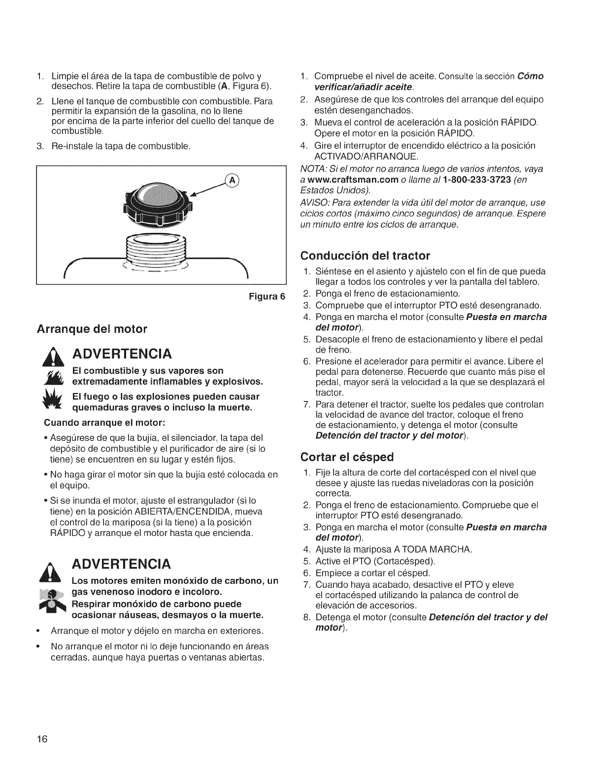
1,
2.
Limpie el Area de la tapa de combustible de polvo y
desechos. Retire la tapa de combustible (A, Figura 6).
Llene el tanque de combustible con combustible. Para
permitir la expansi6n de la gasolina, no Io Ilene
por encima de la parte inferior del cuello del tanque de
combustible.
3. Re-instale la tapa de combustible.
Figura 6
Arranque del motor
ADVERTENCIA
El combustible ysus vapores son
extremadamente inflamables y explosivos.
El fuego olas e×plosiones pueden causar
quemaduras graves o incluso la muerte.
Cuando arranque el motor:
• Asegurese de que la bujia, el silenciador, la tapa del
dep6sito de combustible y el purificador de aire (si Io
tiene) se encuentren en su lugar y esten fijos.
• No haga girar el motor sin que la bujia este colocada en
el equipo.
• Si se inunda el motor, ajuste el estrangulador (si Io
tiene) en la posici6n ABIERTA/ENCENDIDA, mueva
el control de la mariposa (si la tiene) a la posici6n
RA,PIDO y arranque el motor hasta que encienda.
e
e
ADVERTENCIA
Los motores emiten monb×ido de carbono, un
gas venenoso inodoro eincoloro.
Respirar mon6xido de carbono puede
ocasionar n_useas, desmayos ola muerte.
Arranque el motor y dejelo en marcha en exteriores.
No arranque el motor ni Io deje funcionando en Areas
cerradas, aunque haya puertas o ventanas abiertas.
1. Compruebe el nivel de aceite. Consulte la seccion Como
verificar/a_adir aceite.
2. AsegL_rese de que los controles del arranque del equipo
esten desenganchados.
3. Mueva el control de aceleraci6n a la posici6n RA,PIDO.
Opere el motor en la posici6n RA,PIDO.
4. Gire el interruptor de encendido electrico a la posici6n
ACTIVADO/ARRANQUE.
NOTA: Si el motor no arranca luego de varios intentos, vaya
awww.craftsman.com o Ilame al 1-800-233-3723 (en
Estados Unidos).
AVISO: Para extender la vida #til de! motor de arranque, use
ciclos cortos (maximo cinco segundos) de arranque. Espere
un minuto entre los ciclos de arranque.
Conducci6n dei tractor
1. Si6ntese en el asiento y ajt]stelo con el fin de que pueda
Ilegar a todos los controles y ver la pantalla del tablero.
2. Ponga el freno de estacionamiento.
3. Compruebe que el interruptor PTO este desengranado.
4. Ponga en marcha el motor (consulte Puesta en marcha
del motor).
5. Desacople el freno de estacionamiento y libere el pedal
de freno.
6. Presione el acelerador para permitir el avance. Libere el
pedal para detenerse. Recuerde que cuanto mas pise el
pedal, mayor sera la velocidad a la que se desplazara el
tractor.
7. Para detener el tractor, suelte los pedales que controian
la velocidad de avance del tractor, coloque el freno
de estacionamiento, y detenga el motor (consulte
Detencidn del tractor y del motor).
Cortar el cesped
1. Fije la altura de corte del cortacesped con el nivel que
desee y ajuste las ruedas niveladoras con la posici6n
correcta.
2. Ponga el freno de estacionamiento. Compruebe que el
interruptor PTO este desengranado.
3. Ponga en marcha el motor (consulte Puesta en marcha
del motor).
4. Ajuste la mariposa A TODA MARCHA.
5. Active el PTO (Cortacesped).
6. Empiece a cortar el cesped.
7. Cuando haya acabado, desactive el PTO y eleve
el cortacesped utilizando la palanca de control de
elevaci6n de accesorios.
8. Detenga el motor (consulte Detencidn del tractor y del
motor).
16
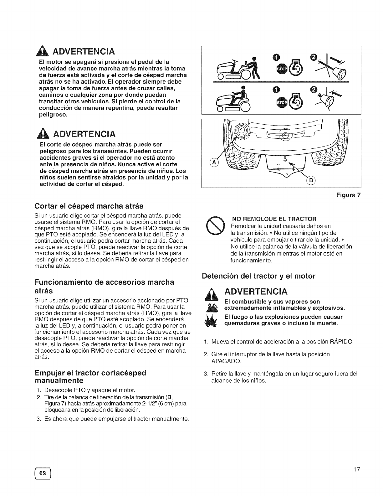
ADVERTENCIA
El motor se apagara si presiona el pedal de la
velocidad de avarice marcha atras mientras la toma
de fuerza esta activada yel corte de cesped marcha
atr_s no se ha activado. El operador siempre debe
apagar la toma de fuerza antes de cruzar calles,
caminos o cualquier zona por donde puedan
transitar otros vehiculos. Si pierde el control de la
conducci6n de manera repentina, puede resultar
peligroso.
ADVERTENCIA
El corte de cesped marcha atras puede ser
peligroso para los transe_ntes. Pueden ocurrir
accidentes graves si el operador no est_ atento
ante la presencia de niSos. Nunca active el corte
de cesped marcha atras en presencia de niSos. Los
ni_os suelen sentirse atraidos por la unidad y por la
actividad de cortar el cesped.
Cortar el c6sped marcha atras
Si un usuario elige cortar el cesped marcha atra.s, puede
usarse el sistema RMO. Para usar la opci6n de cortar el
cesped marcha atra.s (RMO), gire la Ilave RMO despues de
que PTO este acoplado. Se encender_t la luz del LED y, a
continuaci6n, el usuario podr_t cortar marcha atra.s. Cada
vez que se acople PTO, puede reactivar la opci6n de corte
marcha atras, si Io desea. Se deberia retirar la Ilave para
restringir el acceso a la opci6n RMO de cortar el cesped en
marcha atras.
Funcionamiento de accesorios marcha
arras
Si un usuario elige utilizar un accesorio accionado por PTO
marcha atr_ts, puede utilizar el sistema RMO. Para usar la
opci6n de cortar el cesped marcha atras (RMO), gire la Ilave
RMO despues de que PTO este acoplado. Se encendera.
la luz del LED y, a continuaci6n, el usuario podr_t poner en
funcionamiento el accesorio marcha atr_ts. Cada vez que se
desacople PTO, puede reactivar la opci6n de corte marcha
atra.s, si Io desea. Se deberia retirar la Ilave para restringir
el acceso a la opci6n RMO de cortar el cesped en marcha
atr_ts.
Empujar el tractor cortacesped
manualmente
1. Desacople PTO y apague el motor.
2. Tire de la palanca de liberaci6n de la transmisi6n (B,
Figura 7) hacia atr_ts aproximadamente 2-1/2" (6 cm) para
bloquearla en la posici6n de liberaci6n.
3. Es ahora que puede empujarse el tractor manualmente.
O
._ J
Figura 7
®NO REMOLQUE EL TRACTOR
Remolcar la unidad causaria daSos en
la transmisi6n. = No utilice ningt]n tipo de
vehiculo para empujar o tirar de la unidad. =
No utilice la palanca de la va.lvula de liberaci6n
de la transmisi6n mientras el motor este en
funcionamiento.
Detenci6n del tractor yel motor
ADVERTENCIA
El combustible ysus vapores son
extremadamente inflamables y explosivos.
El fuego o las explosiones pueden causar
quemaduras graves oincluso la muerte.
1. Mueva el control de aceleraci6n a la posici6n RAPIDO.
2. Gire el interruptor de la Ilave hasta la posici6n
APAGADO.
3. Retire la Ilave y mantengala en un lugar seguro fuera del
alcance de los ni_os.
17
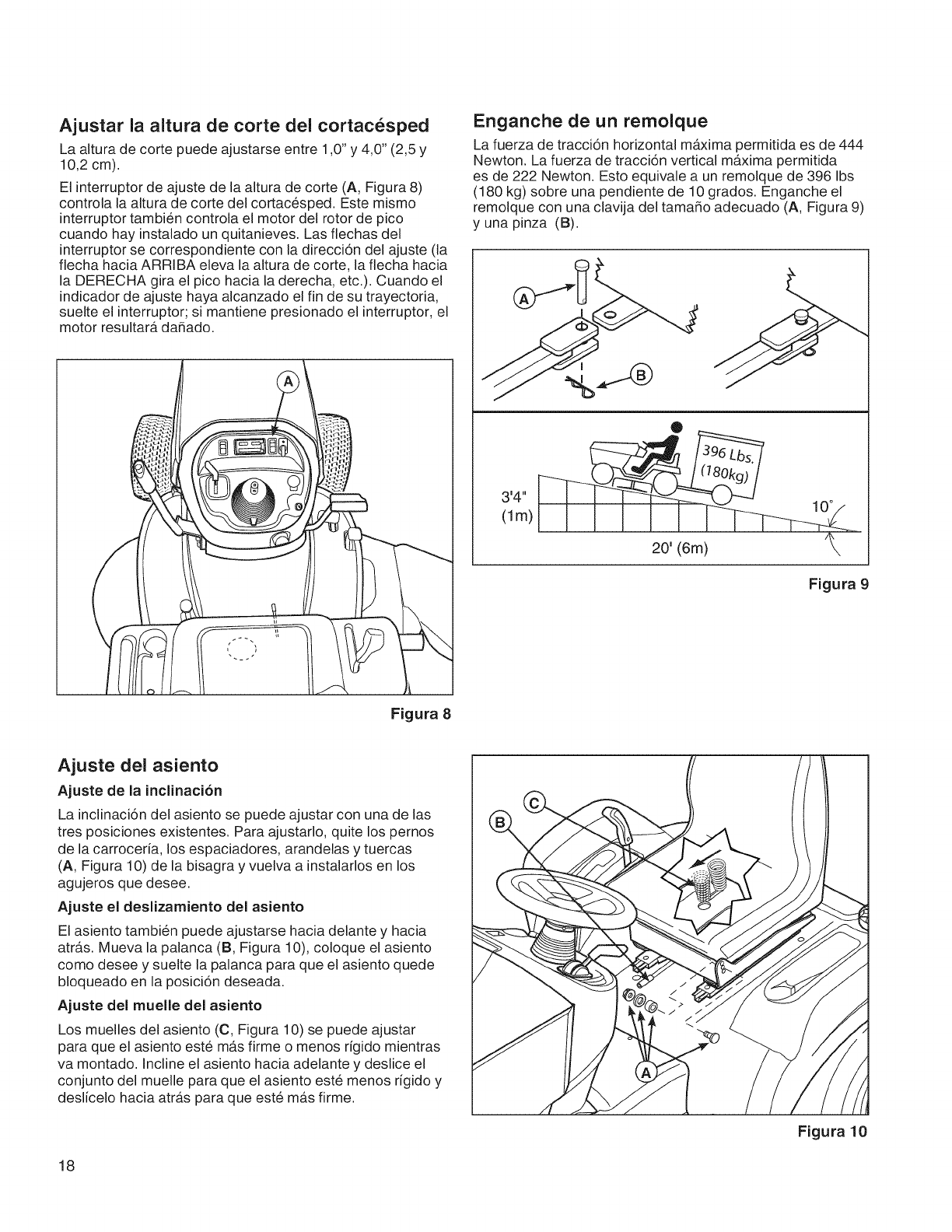
Ajustar la altura de corte del cortac6sped
La altura de corte puede ajustarse entre 1,0" y 4,0" (2,5 y
10,2 cm).
El interruptor de ajuste de la altura de corte (A, Figura 8)
controla la altura de corte del cortacesped. Este mismo
interruptor tambien controla el motor del rotor de pico
cuando hay instalado un quitanieves. Las flechas del
interruptor se correspondiente con la direcci6n del ajuste (la
flecha hacia ARRIBA eleva la altura de corte, la flecha hacia
la DERECHA gira el pico hacia la derecha, etc.). Cuando el
indicador de ajuste haya alcanzado el fin de su trayectoria,
suelte el interruptor; si mantJene presionado el interruptor, el
motor resultara da_ado.
Figura 8
Enganche de un remolque
La fuerza de tracci6n horizontal maxima permitida es de 444
Newton. La fuerza de tracci6n vertical maxima permitida
es de 222 Newton. Esto equivale a un remolque de 396 Ibs
(180 kg) sobre una pendiente de 10 grados. Enganche el
remolque con una clavija del tama_o adecuado (A, Figura 9)
y una pinza (B).
J
®
14. 10°
(lm)
20' (6m)
Figura 9
Ajuste del asiento
Ajuste de la inclJnacJ6n
La inclinaci6n del asiento se puede ajustar con una de las
tres posiciones existentes. Para ajustarlo, quite los pemos
de la carroceria, los espaciadores, arandelas y tuercas
(A, Figura 10) de la bisagra y vuelva a instalarlos en los
agujeros que desee.
Ajuste el deslizamiento del asiento
El asiento tambien puede ajustarse hacia delante y hacia
atras. Mueva la palanca (B, Figura 10), coloque el asiento
como desee y suelte la palanca para que el asiento quede
bloqueado en la posici6n deseada.
Ajuste del muelle del asiento
Los muelles del asiento (C, Figura 10) se puede ajustar
para que el asiento este mas firme o menos rigido mientras
va montado. Incline el asiento hacia adelante y deslice el
conjunto del muelle para que el asiento este menos rigido y
deslicelo hacia atras para que este mas firme.
18
Figura 10
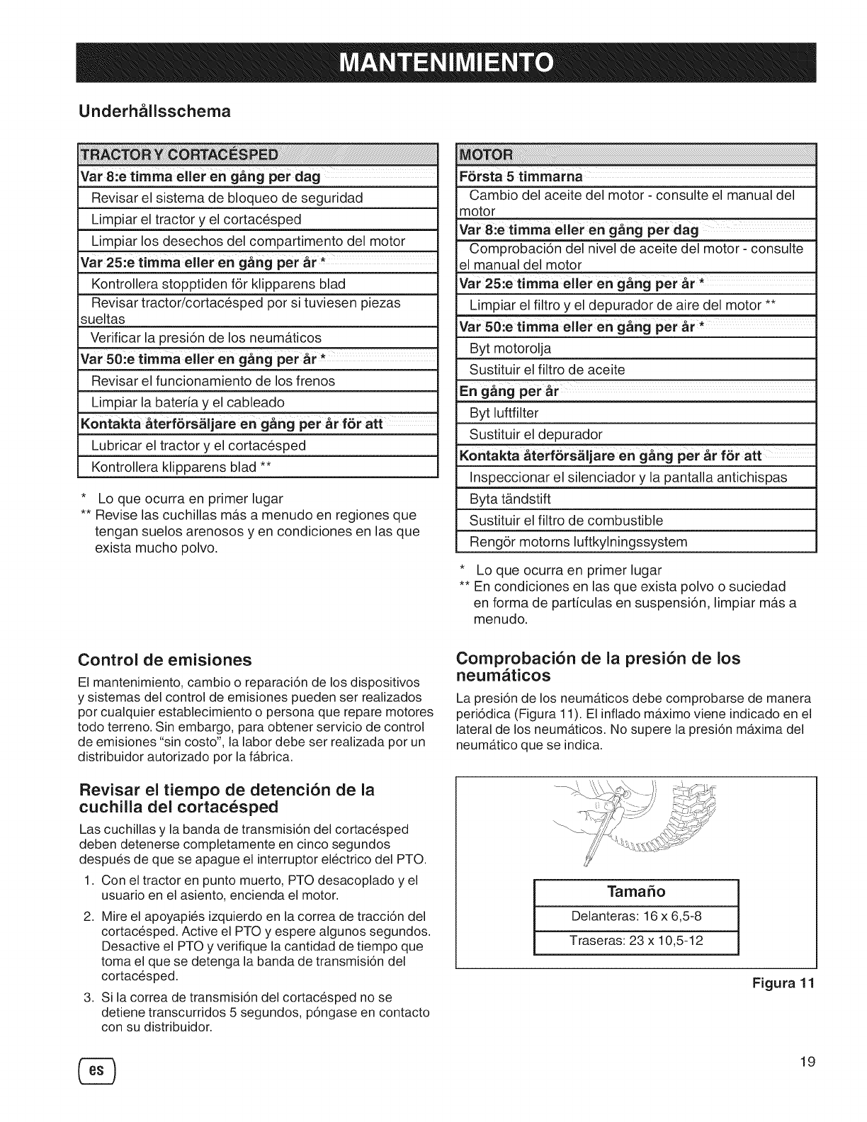
Underh_llsschema
Vat 8:e timma eller en gang per dag
Revisar el sistema de bloqueo de seguridad
Limpiar el tractor y el cortacesped
Lirnpiarlos desechos del compartimento del motor
var25:etimmaelleren gang per &r*
Kontrollera stopptiden f6r klipparens blad
Revisar tractor/cortacesped por si tuviesen piezas
sueltas
Verificar la presion de los neumaticos
Var 50ie timma eller en g_ng per _r,
Revisar el funcionamiento de los frenos
Limpiar la bateria y el cableado
Kontakta &terf6rs_i_en gang peter f6r att
Lubricar el tractor y el cortacesped
Kontrollera klipparens blad **
* Lo que ocurra en primer lugar
** Revise las cuchillas mas a menudo en regiones que
tengan suelos arenosos yen condiciones en las que
exista mucho polvo.
Cambio del aceite del motor - consulte el manual del
motor
var 8:e timma eller en gang per dag
Comprobacion del nivel de aceite del motor - consulte
el manual del motor
var 25:e timma eller en gang per _r _
Limpiar el filtro y el depurador de aire del motor **
var 50:e tim-ma eller en gang per _r*
Byt motorolja
Sustituir el filtro de aceite
En gang per _r
Byt luftfilter
Sustituir el depurador
Kontakta _terf@rs_iljare en gang per _r f@r att
Inspeccionar el silenciador y la pantalla antichispas
Byta t_ndstift
Sustituir el filtro de combustible
Reng6r motorns luftkylningssystem
* Lo que ocurra en primer lugar
** En condiciones en las que exista polvo o suciedad
en forma de particulas en suspension, limpiar mas a
menudo.
Control de emisiones
El mantenimiento, cambio o reparaci6n de los dispositivos
y sistemas del control de emisiones pueden ser realizados
pot cualquier establecimiento o persona que repare motores
todo terreno. Sin embargo, para obtener servicio de control
de emisiones "sin costo", la labor debe ser realizada por un
distribuidor autorizado por la fabrica.
Revisar el tiempo de detencion de la
cuchilla del cortacesped
Las cuchillas y la banda de transmisi6n del cortacesped
deben detenerse completamente en cinco segundos
despues de que se apague el interruptor electrico del PTO.
1. Con el tractor en punto muerto, PTO desacoplado y el
usuario en el asiento, encienda el motor.
2. Mire el apoyapies izquierdo en la correa de tracci6n del
cortacesped. Active el PTO y espere algunos segundos.
Desactive el PTO y verifique la cantidad de tiempo que
toma el que se detenga la banda de transmisi6n del
cortacesped.
3. Si la correa de transmisi6n del cortacesped no se
detiene transcurridos 5 segundos, p6ngase en contacto
con su distribuidor.
Comprobacion de la presion de los
neum_ticos
La presi6n de los neumaticos debe comprobarse de manera
peri6dica (Figura 11). El inflado m_tximo viene indicado en el
lateral de los neum_tticos. No supere la presi6n maxima del
neumatico que se indica.
Tamaffo
Delanteras: 16 x 6,5-8
Traseras: 23 x 10,5-12
Figura 1
19
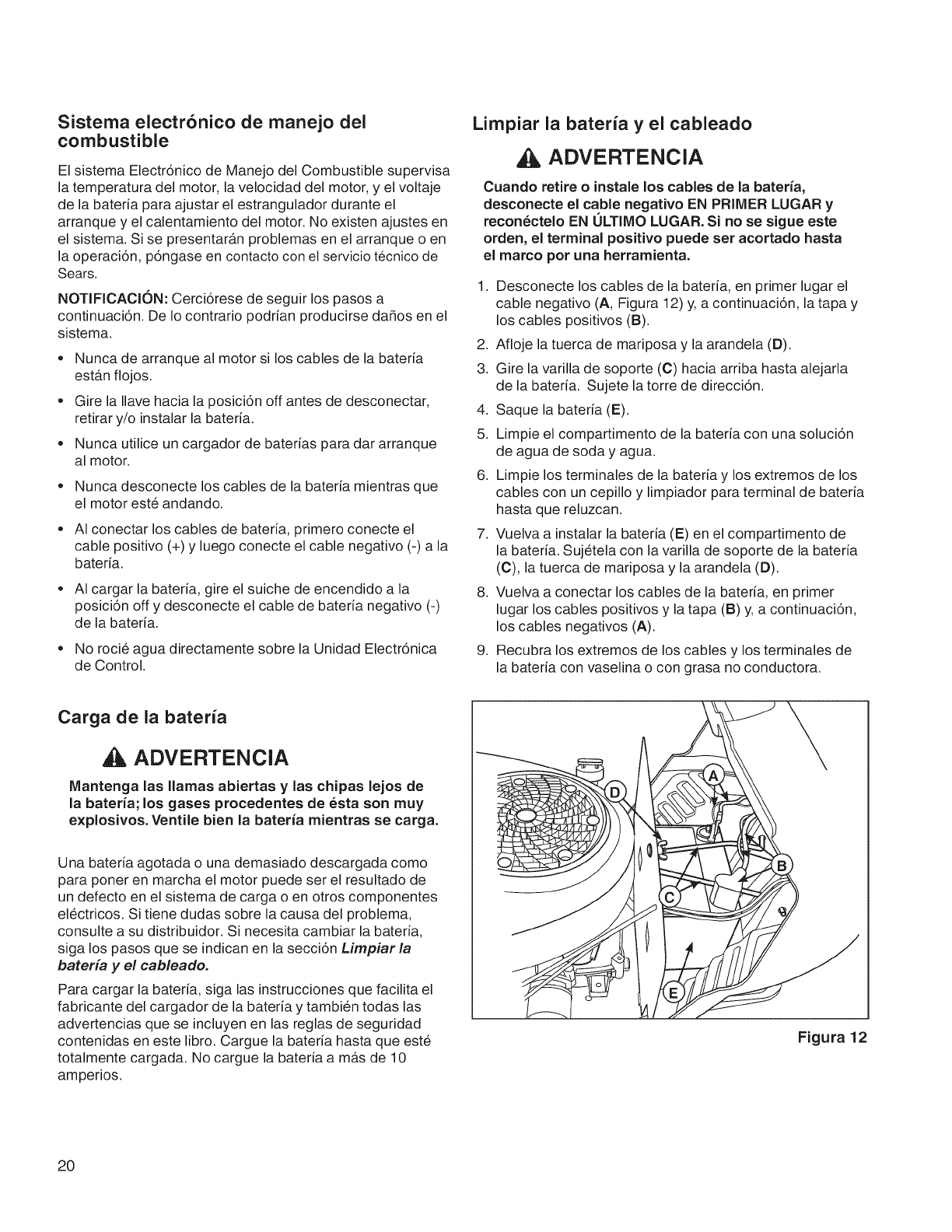
Sistema electronico de manejo del
combustible
El sistema Electr6nico de Manejo del Combustible supervisa
la temperatura del motor, la velocidad del motor, y el voltaje
de la bateria para ajustar el estrangulador durante el
arranque y el calentamiento del motor. No existen ajustes en
el sistema. Si se presentaran problemas en el arranque o en
la operaci6n, p6ngase en contacto con el servicio tecnico de
Sears.
NOTIFICACI6N: Cercidrese de seguir los pasos a
continuaci6n. De Io contrario podrian producirse da_os en el
sistema.
= Nunca de arranque al motor si los cables de la bateria
estan flojos.
= Gire la Ilave hacia la posici6n off antes de desconectar,
retirar y/o instalar la bateria.
Nunca utilice un cargador de baterias para dar arranque
al motor.
= Nunca desconecte los cables de la bateria mientras que
el motor este andando.
= AI conectar los cables de bateria, primero conecte el
cable positivo (4-) y luego conecte el cable negativo (-) a la
bateria.
= AI cargar la bateria, gire el suiche de encendido a la
posici6n off y desconecte el cable de bateria negativo (-)
de la bated&
= No rocie agua directamente sobre la Unidad Electr6nica
de Control.
Limpiar la bateria y el cableado
ADVERTENCIA
Cuando retire o instale los cables de la baterfa,
desconecte el cable negativo EN PRIMER LUGAR y
reconectelo EN 0LTIMO LUGAR. Si no se sigue este
orden, el terminal positivo puede ser acortado hasta
el marco pot una herramienta.
1. Desconecte los cables de la bateria, en primer lugar el
cable negativo (A, Figura 12) y, a continuaci6n, la tapa y
los cables positivos (B).
2. Afloje la tuerca de mariposa y la arandela (D).
3. Gire la varilla de soporte (C) hacia arriba hasta alejarla
de la bateria. Sujete la torre de direcci6n.
4. Saque la bateria (E).
5. Limpie el compartimento de la bateria con una soluci6n
de agua de soda y agua.
6. Limpie los terminales de la bateria y los extremos de los
cables con un cepillo y limpiador para terminal de bateria
hasta que reluzcan.
7. Vuelva a instalar la bateria (E) en el compartimento de
la bateria. Sujetela con la varilla de soporte de la bateria
(C), la tuerca de mariposa y la arandela (D).
8. Vuelva a conectar los cables de la bateria, en primer
lugar los cables positivos y la tapa (B) y, a continuaci6n,
los cables negativos (A).
9. Recubra los extremos de los cables y los terminales de
la bateria con vaselina o con grasa no conductora.
Carga de la baterfa
ADVERTENCIA
Mantenga las llamas abiertas y las chipas lejos de
la baterfa; los gases procedentes de esta son muy
explosivos. Ventile bien la baterfa mientras se carga.
Una bateria agotada o una demasiado descargada como
para poner en marcha el motor puede ser el resultado de
un defecto en el sistema de carga o en otros componentes
electricos. Si tiene dudas sobre la causa del problema,
consulte a su distribuidor. Si necesita cambiar la bateria,
siga los pasos que se indican en la secci6n Lirnpiar la
bateria y el cableado.
Para cargar la bateria, siga las instrucciones que facilita el
fabricante del cargador de la bateria y tambien todas las
advertencias que se incluyen en las reglas de seguridad
contenidas en este libro. Cargue la bateria hasta que este
totalmente cargada. No cargue la bateria a m_ts de 10
amperios.
Figura 12
20
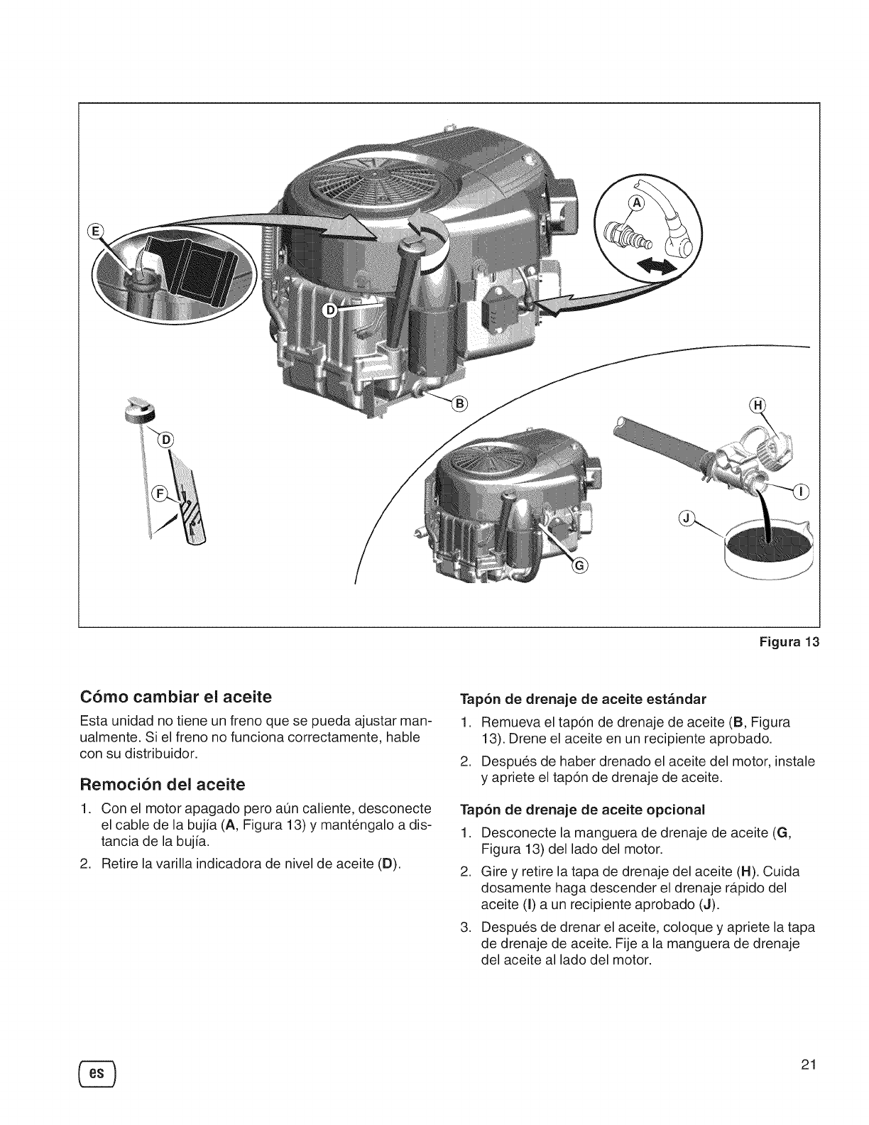
Figura 13
Como cambiar el aceite
Esta unidad no tiene un freno que se pueda ajustar man-
ualmente. Si el freno no funciona correctamente, hable
con su distribuidor.
Remocibn del aceite
1. Con el motor apagado pero aun caliente, desconecte
el cable de la bujia (A, Figura 13) y mantengalo a dis-
tancia de la bujia.
2. Retire la varilla indicadora de nivel de aceite (D).
Tap6n de drenaje de aceite estandar
1. Remueva el tapon de drenaje de aceite (B, Figura
13). Drene el aceite en un recipiente aprobado.
2. Despues de haber drenado el aceite del motor, instale
y apriete el tapon de drenaje de aceite.
Tap6n de drenaje de aceite opcional
1. Desconecte la manguera de drenaje de aceite (G,
Figura 13) del lado del motor.
2. Gire y retire la tapa de drenaje del aceite (H). Cuida
dosamente haga descender el drenaje rapido del
aceite (I) a un recipiente aprobado (J).
3. Despues de drenar el aceite, coloque y apriete la tapa
de drenaje de aceite. Fije a la manguera de drenaje
del aceite al lado del motor.
21
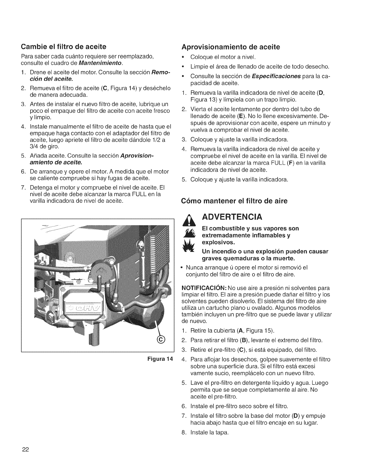
Cambie el filtro de aceite
Para saber cada cuanto requiere ser reemplazado,
consulte el cuadro de Mantenimiento.
1. Drene el aceite del motor. Consulte la seccion Remo-
cr_n del aceite.
2. Remueva el filtro de aceite (C, Figura 14) y desechelo
de manera adecuada.
.
.
.
Antes de instalar el nuevo filtro de aceite, lubrique un
poco el empaque del filtro de aceite con aceite fresco
y limpio.
Instale manualmente el filtro de aceite de hasta que el
empaque haga contacto con el adaptador del filtro de
aceite, luego apriete el filtro de aceite dandole 1/2 a
3/4 de giro.
Adada aceite. Consulte la seccion Aprovision-
amiento de aceite.
6. De arranque y opere el motor. A medida que el motor
se caliente compruebe si hay fugas de aceite.
7. Detenga el motor y compruebe el nivel de aceite. El
nivel de aceite debe alcanzar la marca FULL en la
varilla indicadora de nivel de aceite.
Figura 14
Aprovisionamiento de aceite
• Coloque el motor a nivel.
• Limpie el area de Ilenado de aceite de todo desecho.
• Consulte la seccion de Especificaciones para la ca-
pacidad de aceite.
1. Remueva la varilla indicadora de nivel de aceite (D,
Figura 13) y limpiela con un trapo limpio.
2. Vierta el aceite lentamente pot dentro del tubo de
Ilenado de aceite (E). No Io Ilene excesivamente. De-
spues de aprovisionar con aceite, espere un minuto y
vuelva a comprobar el nivel de aceite.
3. Coloque y ajuste la varilla indicadora.
4. Remueva la varilla indicadora de nivel de aceite y
compruebe el nivel de aceite en la varilla. El nivel de
aceite debe alcanzar la marca FULL (F) en la varilla
indicadora de nivel de aceite.
5. Coloque y ajuste la varilla indicadora.
Como mantener el filtro de aire
ADVERTENCIA
El combustible y sus vapores son
extremadamente inflamables y
explosivos.
Un incendio o una explosion pueden causar
graves quemaduras o la muerte.
• Nunca arranque Oopere el motor si removio el
conjunto del filtro de aire o el filtro de aire.
NOTIFICACION: No use aire a presion ni solventes para
limpiar el filtro. El aire a presion puede dadar el filtro y los
solventes pueden disolverlo. El sistema del filtro de aire
utiliza un cartucho piano u ovalado. Algunos modelos
tambien incluyen un pre-filtro que se puede lavar y utilizar
de nuevo.
1. Retire la cubierta (A, Figura 15).
2. Para retirar el filtro (B), levante el extremo del filtro.
3. Retire el pre-filtro (C), siesta equipado, del filtro.
4. Para aflojar los desechos, golpee suavemente el filtro
sobre una superficie dura. Si el filtro esta excesi
vamente sucio, reemplacelo con un nuevo filtro.
5. Lave el pre-filtro en detergente liquido y agua. Luego
permita que se seque completamente al aire. No
aceite el pre-filtro.
6. Instale el pre-filtro seco sobre el filtro.
7. Instale el filtro sobre la base del motor (D) y empuje
hacia abajo hasta que el filtro encaje en su lugar.
8. Instale la tapa.
22
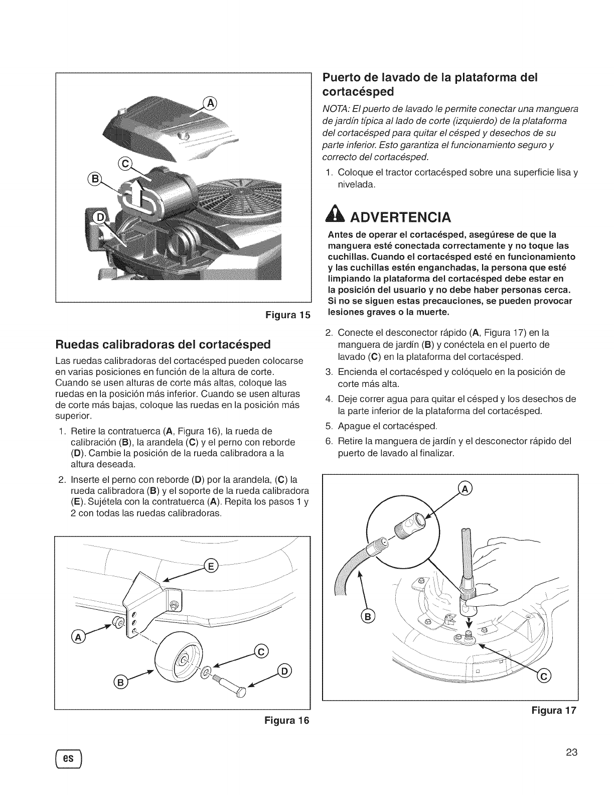
Figura 15
Ruedas calibradoras del cortacesped
Las ruedas calibradoras del cortacesped pueden colocarse
en varias posiciones en funci6n de la altura de corte.
Cuando se usen alturas de corte m_ts altas, coloque las
ruedas en la posici6n m_ts inferior. Cuando se usen alturas
de corte m_ts bajas, coloque las ruedas en la posici6n m_ts
superior.
1. Retire la contratuerca (A, Figura 16), la rueda de
calibraci6n (B), la arandela (C) y el perno con reborde
(D). Cambie la posici6n de la rueda calibradora a la
altura deseada.
2, Inserte el perno con reborde (D) por la arandela, (C) la
rueda calibradora (B) y el soporte de la rueda calibradora
(E). Sujetela con la contratuerca (A). Repita los pasos 1 y
2 con todas las ruedas calibradoras.
Puerto de lavado de la plataforma del
cortacesped
NOTA: El puerto de lavado le permite conectar una manguera
de jardin tipica al lado de corte (izquierdo) de la plataforma
de! cortacesped para quitar el cesped y desechos de su
parte inferior. Esto garantiza el funcionamiento seguro y
correcto de! cortacesped.
1. Coloque el tractor cortacesped sobre una superficie lisa y
nivelada.
ADVERTENCIA
Antes de operar el cortac_sped, asegQrese de que la
manguera est_ conectada correctamente y no toque las
cuchillas. Cuando el cortac_sped est_ en funcionamiento
y las cuchillas est_n enganchadas, la persona que est_
limpiando la plataforma del cortac_sped debe estar en
la posici6n del usuario y no debe haber personas cerca.
Si no se siguen estas precauciones, se pueden provocar
lesiones graves o la muerte.
2, Conecte el desconector r_tpido (A, Figura 17) en la
manguera de jardin (B) y conectela en el puerto de
lavado (C) en la plataforma del cortacesped.
Encienda el cortacesped y col6quelo en la posici6n de
corte mas alta.
3,
4. Deje correr agua para quitar el cesped y los desechos de
la parte inferior de la plataforma del cortacesped.
5. Apague el cortacesped.
6. Retire la manguera de jardin y el desconector r_tpido del
puerto de lavado al finalizar.
Figura 16 Figura 17
23
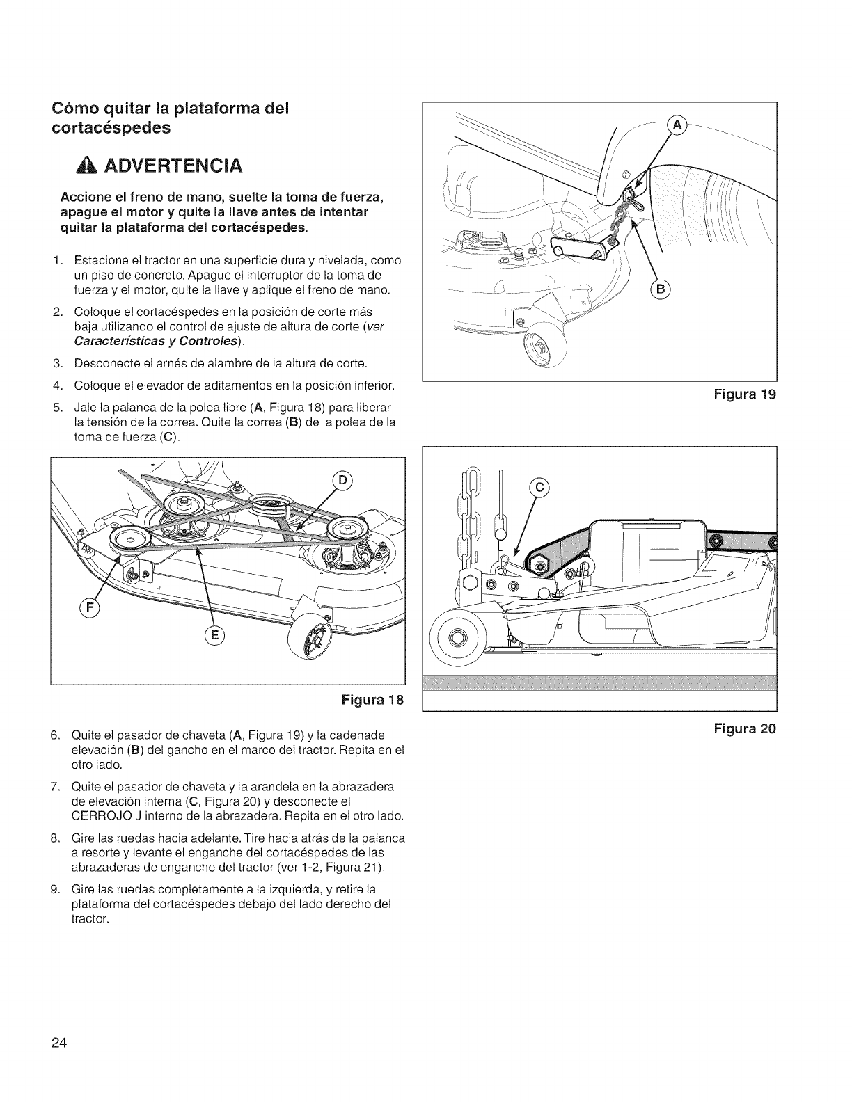
Como quitar la plataforma del
cortacespedes
ADVERTENCIA
Accione el freno de mano, suelte la toma de fuerza,
apague el motor y quite la Ilave antes de intentar
quitar la plataforma del cortacespedes.
1. Estacione el tractor en una superficie dura y nivelada, como
un piso de concreto. Apague el interruptor de la toma de
fuerza y et motor, quite la llave y aplique el freno de mano.
2. Coloque el cortacespedes en la posicion de corte ma_s
baja utilizando et control de ajuste de altura de corte (ver
Caracterfsticas y Controles).
3.
4.
5.
Desconecte et arnes de alambre de la attura de corte.
Coloque el elevador de aditamentos en la posicion inferior.
Jale ta patanca de la potea libre (A, Figura 18) para liberar
la tension de ta correa. Quite la correa (B) de la polea de la
toma de fuerza (C).
/
Figura 19
6.
7.
8.
9.
Figura 18
Quite et pasador de chaveta (A, Figura 19) y la cadenade
elevacion (B) det gancho en et marco del tractor. Repita en et
otro lado.
Quite el pasador de chaveta y la arandela en la abrazadera
de elevacion intema (C, Figura 20) y desconecte et
CERROJO J interno de la abrazadera. Repita en el otro lado.
Gire las ruedas hacia adetante. Tire hacia atra_sde la patanca
a resorte y levante et enganche del cortacespedes de las
abrazaderas de enganche del tractor (ver 1-2, Figura 21 ).
Gire tas ruedas comptetamente a la izquierda, y retire la
ptataforma del cortacespedes debajo det lado derecho del
tractor.
Figura 20
24
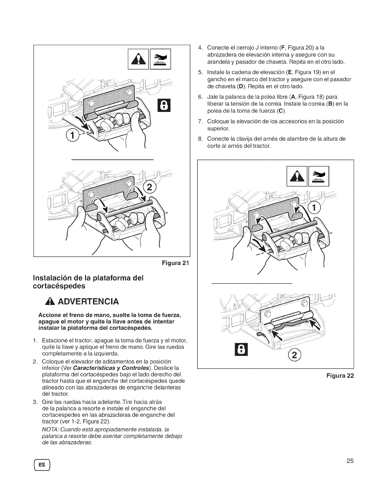
Figura21
Instalaci6n de la plataforma del
cortacespedes
ADVERTENCIA
Accione el freno de mano, suelte la toma de fuerza,
apague el motor y quite la Ilave antes de intentar
instalar la plataforma del cortacespedes.
1,
2,
3,
Estacione el tractor, apague la toma de fuerza y el motor,
quite la Ilave y aplique el freno de mano. Gire las ruedas
completamente a la izquierda.
Coloque el elevador de aditamentos en la posici6n
inferior (Ver Caracteristicas y Controles). Deslice la
plataforma del cortacespedes bajo el lado derecho del
tractor hasta que el enganche del cortacespedes quede
alineado con las abrazaderas de enganche delanteras
del tractor.
Gire las ruedas hacia adelante. Tire hacia atra.s
de la palanca a resorte e instale el enganche del
cortacespedes en las abrazaderas de enganche del
tractor (ver 1-2, Figura 22).
NOTA: Cuando esta apropiadamente instalada, la
palanca a resorte debe asentar completamente debajo
de las abrazaderas.
4,
5,
6,
7,
,
Conecte el cerrojo J interno (F, Figura 20) a la
abrazadera de elevaci6n interna y asegure con su
arandela y pasador de chaveta. Repita en el otro lado.
Instale la cadena de elevaci6n (E, Figura 19) en el
gancho en el marco del tractor y asegure con el pasador
de chaveta (D). Repita en el otro lado.
Jale la palanca de la polea libre (A, Figura 18) para
liberar la tensi6n de la correa. Instale la correa (B) en la
polea de la toma de fuerza (C).
Coloque la elevaci6n de los accesorios en la posici6n
superior.
Conecte la clavija del arnes de alambre de la altura de
corte al arnes del tractor.
®
Figura 22
®25
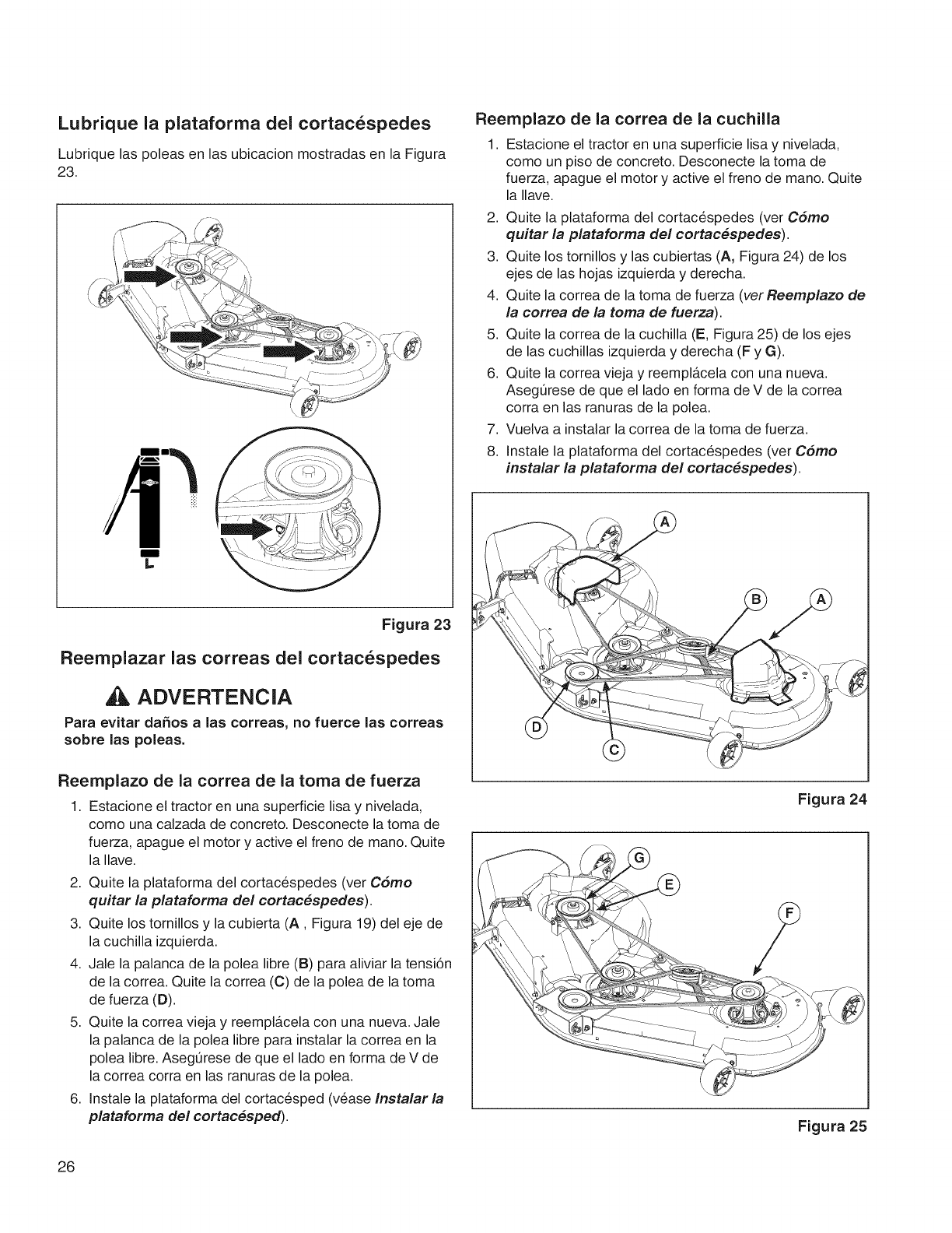
Lubrique la plataforma del cortacespedes
Lubrique las poleas en las ubicacion mostradas en la Figura
23.
m
Reernplazo de la correa de la cuchilla
1. Estacione el tractor en una superficie lisa y nivelada,
como un piso de concreto. Desconecte la toma de
fuerza, apague el motor y active el freno de mano. Quite
la Ilave.
2. Quite la plataforma del cortacespedes (ver Cdmo
quitar la plataforma del cortac_spedes).
3. Quite los tornillos y las cubiertas (A, Figura 24) de los
ejes de las hojas izquierda y derecha.
4. Quite la correa de la toma de fuerza (verReemplazo de
la correa de la toma de fuerza).
5. Quite la correa de la cuchilla (E, Figura 25) de los ejes
de las cuchillas izquierda y derecha (F y G).
6. Quite la correa vieja y reemplacela con una nueva.
Asegurese de que el lado en forma de V de la correa
corra en las ranuras de la pole&
7. Vuelva a instalar la correa de la toma de fuerza.
8. Instale la plataforma del cortacespedes (ver C6mo
instalar la plataforma del cortac_spedes).
Figura 23
Reemplazar las correas del cortacespedes
ADVERTENCIA
Para evitar da_os alas correas, no fuerce las correas
sobre las poleas.
Reemplazo de la correa de la toma de fuerza
1. Estacione el tractor en una superficie lisa y nivelada,
como una calzada de concreto. Desconecte la toma de
fuerza, apague el motor y active el freno de mano. Quite
la Ilave.
2. Quite la plataforma del cortacespedes (ver Cdmo
quitar la plataforma de! cortac_spedes).
3. Quite los tomillos y la cubierta (A, Figura 19) del eje de
la cuchilla izquierda.
4. Jale la palanca de la polea libre (B) para aliviar la tensi6n
de la correa. Quite la correa (C) de la polea de la toma
de fuerza (D).
5. Quite la correa vieja y reempl_tcela con una nueva. Jale
la palanca de la polea libre para instalar la correa en la
polea libre. Asegt]rese de que el lado en forma de V de
la correa corra en las ranuras de la pole&
6. Instale la plataforma del cortacesped (vease Instalar la
plataforma del cortac#sped).
Figura 24
Figura 25
26
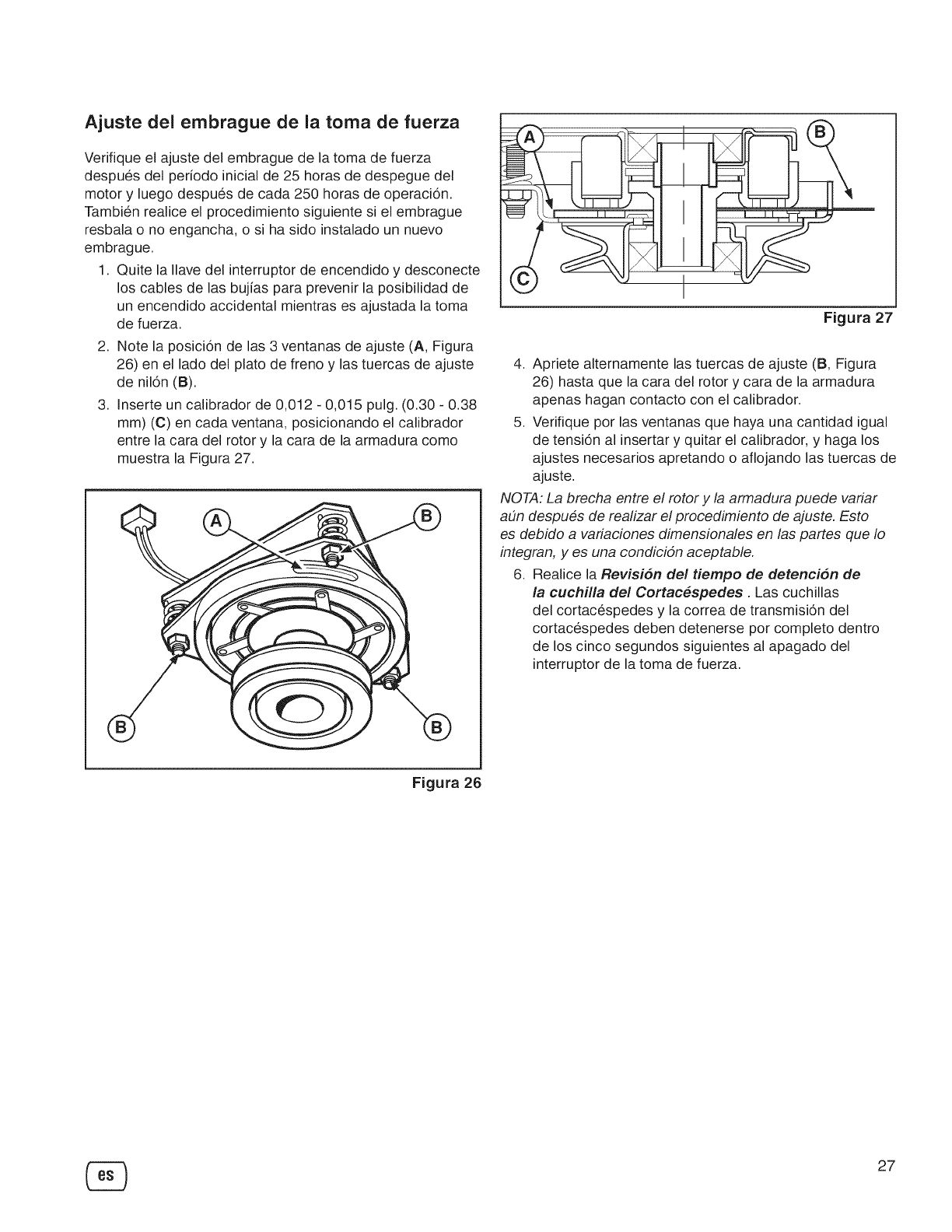
Ajuste del embrague de la toma de fuerza
Verifique el ajuste del embrague de la toma de fuerza
despues del periodo inicial de 25 horas de despegue del
motor y luego despues de cada 250 horas de operaci6n.
Tambien realice el procedimiento siguiente si el embrague
resbala o no engancha, o si ha sido instalado un nuevo
embrague.
1. Quite la Ilave del interruptor de encendido y desconecte
los cables de las bujias para prevenir la posibilidad de
un encendido accidental mientras es ajustada la toma
de fuerza.
2. Note la posici6n de las 3 ventanas de ajuste (A, Figura
26) en el lado del plato de freno y las tuercas de ajuste
de nil6n (B).
3. Inserte un calibrador de 0,012 - 0,015 pulg. (0.30 - 0.38
mm) (C) en cada ventana, posicionando el calibrador
entre la cara del rotor y la cara de la armadura como
muestra la Figura 27.
®
Figura 27
4. Apriete alternamente las tuercas de ajuste (B, Figura
26) hasta que la cara del rotor y cara de la armadura
apenas hagan contacto con el calibrador.
5. Verifique por las ventanas que haya una cantidad igual
de tensi6n al insertar y quitar el calibrador, y haga los
ajustes necesarios apretando o aflojando las tuercas de
ajuste.
NOTA: La brecha entre el rotor y la armadura puede variar
a#n despues de realizar el procedimiento de ajuste. Esto
es debido a variaciones dimensionales en las partes que Io
integran, yes una condicidn aceptable.
6. Realice la Revision del tiempo de detencion de
la cuchilla de! Cortac_spedes . Las cuchillas
del cortacespedes y la correa de transmisi6n del
cortacespedes deben detenerse por completo dentro
de los cinco segundos siguientes al apagado del
interruptor de la toma de fuerza.
Figura 26
27
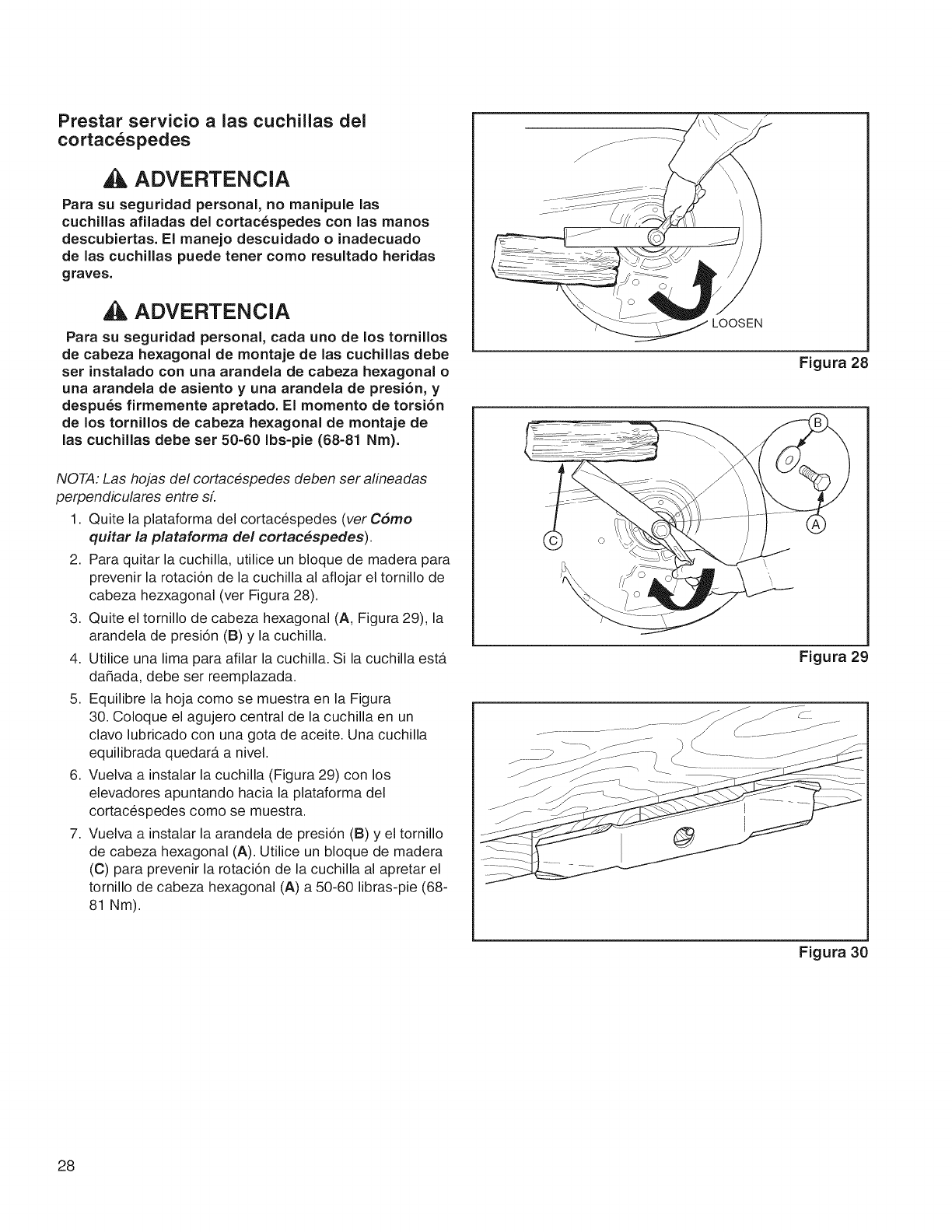
Prestar servicio a las cuchillas del
cortacespedes
ADVERTENCIA
Para su seguridad personal, no manipule las
cuchillas afiladas del cortacespedes con las manos
descubiertas. El manejo descuidado o inadecuado
de las cuchillas puede tener como resultado heridas
graves.
ADVERTENCIA
Para su seguridad personal, cada uno de los tornillos
de cabeza hexagonal de montaje de las cuchillas debe
ser instalado con una arandela de cabeza hexagonal o
una arandela de asiento y una arandela de presi6n, y
despues firmemente apretado. El momento de torsi6n
de los tornillos de cabeza hexagonal de montaje de
las cuchillas debe ser 50-60 Ibs-pie (68-81 Nm).
NOTA: Las hojas del cortacespedes deben ser alineadas
perpendiculares entre sL
1. Quite la plataforma del cortacespedes (ver Cdmo
quitar la plataforma de! cortac_spedes).
2. Para quitar la cuchilla, utilice un bloque de madera para
prevenir la rotaci6n de la cuchilla al aflojar el tornillo de
cabeza hezxagonal (ver Figura 28).
3. Quite el tornillo de cabeza hexagonal (A, Figura 29), la
arandela de presi6n (B) y la cuchilla.
4. Utilice una lima para afilar la cuchilla. Si la cuchilla ester
da_ada, debe ser reemplazada.
5. Equilibre la hoja como se muestra en la Figura
30. Coloque el agujero central de la cuchilla en un
clavo lubricado con una gota de aceite. Una cuchilla
equilibrada quedar_t a nivel.
6. Vuelva a instalar la cuchilla (Figura 29) con los
elevadores apuntando hacia la plataforma del
cortacespedes como se muestra.
7. Vuelva a instalar la arandela de presi6n (B) y el tornillo
de cabeza hexagonal (A). Utilice un bloque de madera
(C) para prevenir la rotaci6n de la cuchilla al apretar el
tornillo de cabeza hexagonal (A) a 50-60 libras-pie (68-
81 Nm).
LOOSEN
Figura 28
Figura 29
Figura 30
28
AImacenaje
ADVERTENCIA
Nunca almacene la unidad (con combustible)
en una estructura cerrada y con poca
ventilaci6n. Los vapores del combustible
pueden trasladarse a una fuente de ignici6n
(tal como una caldera, un calentador de agua,
etc.) y causar una explosi6n. El vapor del
combustible tambien es t6xico para seres
humanos yanimales.
AI almacenar combustible o equipos con combustible
en el tanque
Almacenar lejos de calderas, estufas, calentadores de
agua u otros aparatos con luces-piloto u otras fuentes de
ignici6n, ya que pueden prender fuego a vapores de la
gasolina.
Equipo
Desengrane el PTO, desengrane el freno de
estacionamiento y retire la Ilave.
La vida util de la bateria sera superior si se la retira.
Col6quelo en un lugar fresco y seco y carguelo por
completo alrededor de una vez al mes. Si se deja la
bateria en la unidad, desconecte el cable negativo.
Sistema de combustible
El combustible puede deteriorarse si permanece
almacenado durante mas de 30 dias. El combustible
deteriorado hace que se acumulen depositos de acido
y resina en el sistema de combustible o en las piezas
principales del carburador. Para que el combustible se
mantenga fresco, utilice el estabilizador.
No es necesario drenar la gasolina del motor si se
a_ade un estabilizador de combustible siguiendo las
instrucciones. Haga funcionar el motor durante dos
minutos para que el estabilizador circule por el sistema de
combustible antes de almacenarlo.
Aceite de motor
Mientras el motor sigue estando caliente, cambie el aceite
del motor. Consulte el Manual del Motor.
Antes de poner en marcha la unidad despues de su
almacenaje:
• Verifique todos los niveles de liquido. Verifique todos
los items de mantenimiento.
• Realice todas las verificaciones y los procedimientos
recomendados en este manual.
• Permita que el motor se caliente durante varios
minutos antes de utilizarlo.
29

PROBLEIViA BUSQUE SOLUCION
Et pedal del freno no esta presio- Presione por completo el pedal del freno.
nado.
El interruptor de toma de fuerza Coloquelo en la posicion de apagado.
(embrague etectrico) se encuentra
en la posicion de ENCENDIDO.
El control de crucero esta accio- Mueva la peritla a la posicion de NEUTRO/APAGADO.
nado.
Combustible agotado. Si et motor esta catiente, dejeto enfriar y vuelva a Ilenar el deposito
de combustible.
El fusible esta quemado. Sustituya el fusible o pongase en contacto con el servicio tecnico
de Sears.
Los terminates de la bateria requi- Consulte la seccion Limpiar la bater[a y el cableado.
Et motor no funciona ni eren limpieza.
arraRca.
La bater[a esta descargada o Recargue o cambie la bateria. Utilice Die Hard Gold n9 50785.
agotada.
El cableado esta suelto o roto. Revise visuatmente et cableado. Si los cables estan rafdos o rotos,
consulte con el distribuidor autorizado.
Solenoide o motor de arranque Pongase en contacto con el servicio tecnico de Sears.
defectuosos.
Interruptor de interbloqueo de se- Pongase en contacto con el servicio tecnico de Sears.
guridad defectuoso.
Hay agua en el combustible. Pongase en contacto con el servicio tecnico de Sears.
La gasolina es antigua o esta muy Pongase en contacto con el servicio tecnico de Sears.
usada.
La mezcla de combustible es de- Limpie el filtro de aire.
El motor no arranca masiado rica.
bien o no funciona
bien. El motor tiene otro probtema. Pongase en contacto con el servicio tecnico de Sears.
Bajo nivel de aceite. Compruebe o reponga el aceite segL_nsea necesario.
El motor da golpes. Uso de aceite de grado incorrecto. Consulte Tabla de recomendaciones de aceite.
Et motor se catienta demasiado at Pongase en contacto con el servicio tecnico de Sears.
funcionar.
E×cesivo consumo de Uso de aceite de grado incorrecto. Consulte Tabla de recomendaciones de aceite.
lubricante.
Exceso de aceite en et ca_rter. Drene el exceso de aceite.
El tubo de escape est& El filtro de aire est,_ sucio. Consulte la secci6n Mantenimiento de/filtro de aire.
ennegrecido.
Los pedales det acelerador no Presione los pedales.
estan presionados.
La palanca de liberacion de la Muevala hasta la posicion de MARCHA.
transmision se encuentra en la
El motor funciona pero posicion de EMPUJE.
el tractor no avanza. Et freno de estacionamiento esta Desenganche el freno de estacionamiento.
accionado.
La correa de transmision de trac- Pongase en contacto con el servicio tecnico de Sears.
cion esta rota o se resbata.
30
Localizacion de fallas del tractor (continuacion)
PROBLEMA BUSQUE SOLUCION
El freno no se man- El freno interno estA desgastado. Pongase en contacto con el servicio tecnico de Sears.
tiene.
La conexion de la direccion esta Pongase en contacto con el servicio tecnico de Sears.
suelta.
La direcci6n del tractor Inflado incorrecto de los neumAti- Consulte la secci6n Comprobar la presion de los
est_ dura o su manejo cos. neumbticos.
es deficiente. Los rodamientos del eje de la Pongase en contacto con el servicio tecnico de Sears.
rueda delantera estAn secos.
Localizacion de fallas del cortacesped
PROBLEMA BUSQUE SOLUClON
Et varillaje de etevacion no esta Pongase en contacto con el servicio tecnico de Sears.
El cortac_sped no se conectado en forma adecuada o
eleva, presenta da5os.
El cortacesped no estA bien nive- Nivetacion de la cortacesped. Consulte Guia de Instalaci6n.
El corte que hace lado.
el cortac_sped es Los neuma_ticos det tractor no Consulte la seccion Verificacion de la presion de los neumAticos.
desigual, estAn inflados adecuadamente.
La velocidad del motor es demasi- AjQstelo a toda marcha.
ado lenta.
El corte que hace el La vetocidad de avance es de- DisminQyalo.
cortac_sped tiene un masiado rApida.
aspecto irregular. El cortacesped tiene otro prob- Pongase en contacto con et servicio tecnico de Sears.
lema.
La velocidad del motor es demasi- AjQsteto a toda marcha.
ado lenta.
La velocidad de avance es de- DisminQyalo.
masiado rApida.
El filtro de aire esta sucio u ob- Consulte la secci6n Mantenimiento del filtro de aire.
struido.
El motor se atasca Altura de corte demasiado baja. Corte el cesped con la maxima altura en la primera pasada.
facilmente con el corta=
c_sped en marcha. Conducto de descarga atascado. Corte cesped con la descarga apuntando hacia una zona cortada
previamente.
El motor no atcanza la temperatura Arranque el motor durante atgunos minutos para calentado.
de funcionamiento.
Arranque del cortacesped en Arranque el motor en un Area limpia.
cesped alto.
Et cortacesped tiene otto prob- Pongase en contacto con el servicio tecnico de Sears.
Vibraciones e×cesivas lema.
en el cortac_sped.
La toma de fuerza no esta en- Enganche la toma de fuerza.
El motor funciona y et
tractor tiene tracci6n, ganchada.
pero el cortac_sped no Et cortacesped tiene otro prob- Pongase en contacto con et servicio tecnico de Sears.
se mueve, lema.
31
MOTOR
Briggs & Stratton
Fabricado por
Modelo
Cabailos de fuerza
Desplazamiento
Sistema electrico
Capacidad de aceite
CHASIS
Capacidad del tanque
de combustible
Ruedas delanteras
Ruedas traseras
Briggs & Stratton®
Professional Series TM
26 Gross HP @ 3400 +/- 100 rpm
44,2 cu pulg. (724 cc)
Alternador: 16 amperios
Bateria: 12 voltios, 340 CCA
Die Hard Gold n ° 50785
1,9 L (64 oz)
13,6 L (3,6 galones)
Dimensiones de los neumaticos:
16 x 6,50-8
Dimensiones de los neumaticos:
23 x 10,5-12
TRANSMISION K66
Tipo
Fluido hidraulico
Capacidad
Velocidades
Velocidades a 3400 rpm
Fuerza de torsion
continua
Torsi6n hidrostatica K66
20w 30 Premium Engine Oil
2,5 L (2,6 qt)
Hacia delante: 9,6 km/h (0-6,1 MPH)
Marcha atras: 4,8 km/h (0-3,0 MPH)
310 ft-lbs (419 Nm)
CORTACESPED
Ancho de corte 132,1 cm (52")
NQmero de cuchillas 3
Plataforma de cubierta base Descarga por lado
Altura de corte 2,5 y 10,2 cm (t ,0 y 4,0 pulg.)
Posiciones de corte Infinito
MEDIDAS
Largo general 190,5 cm (75")
Ancho general 154,9 cm (61")
AItura 119,4 cm (47")
Clasificacion de Potencia
La clasificacion de potencia bruta para el modelo de motor de gasolina individual esta etiquetada de acuerdo con el co-
digo J1940 (Small Engine Power & Torque Rating Procedure) de la SAE (Society of Automotive Engineers), y la clasifi-
cacion de rendimiento ha sido obtenida y corregida de conformidad con SAE J1995 (Revision 2002-05). Los valores de
torsion se derivan a 3060 RPM. Los valores de los caballos de fuerza se derivan a 3600 RPM. Las curvas de potencia
bruta se pueden ver en www.BRIGGSandSTRATTON.COM. Los valores de potencia neta se obtienen con el filtro de
aire y la ventilacion instalados mientras que los valores de la potencia bruta se reunen sin estos accesorios instala-
dos. La potencia bruta efectiva del motor sera superior a la de la potencia del motor y se vera afectada pot, entre otros
elementos, las condiciones ambientales de funcionamiento y variabilidad entre motores. Dado el amplio conjunto de
productos en que se colocan los motores, el motor de gasolina no desarrollara la potencia bruta clasificada cuando se
utilice en un componente de equipamiento de motor determinado. Estas diferencias son debidas a una amplia variedad
de factores, incluidos, sin exclusion de otros, diferentes componentes del motor (limpiadores de aire, tubos de escape,
carga, refrigeracion, carburador, bomba de combustible, etc.), limitaciones de aplicacion, condiciones ambientales de
funcionamiento (temperatura, humedad, altitud) y la variabilidad entre motores. Debido alas limitaciones de fabricacion
y capacidad, Briggs & Stratton podra sustituir una mayor potencia clasificada para este motor de serie.
Piezas y accesorios
Consulte con su distribuidor autorizado.
32
GARANTJATOTALDEFABRICACION
DURANTEUNPERJODODETRESANOSacontardesdelafechadecompra,todaslaspiezasnosujetasadesgaste
deesteequipoestangarantizadascontracualquierdefectodematerialomanodeobra.Cualquierpiezanosujetaa
desgastedefectuosaserareparadademaneragratuitaadomiciliooserareemplazadasiesimposiblerepararla.
DURANTEUNPERJODODECINCOANOSacontardesdelafechadecompra,elarmazonyelejedelanterodeeste
equipoestangarantizadoscontracualquierdefectodematerialomanodeobra.Unarmazonoejedelanterodefec-
tuososeranreparadosdemaneragratuitaadomiciliooseransustituidossiesimposiblerepararlos.
DURANTEUNPERJODODE90DIASacontardesdelafechadecompra,labateria(unapiezasujetaadesgaste)de
esteequipoestagarantizadacontracualquierdefectodematerialomanodeobra(nuestraspruebasdemuestranque
nopuederetenerunacarga).Unabateriadefectuosaserasustituidaadomiciliodemaneratotalmentegratuita.
GARANTIAUMITADADEPORVlDAADICIONALPARAELEJEDELANTERODEHIERROFUNDIDO(sielequipo
estaequipadocon61).
Elejedelanterodehierrofundido(sielequipoestaequipadoconelmismo)deesteequipoestagarantizadocontracu-
alquierdefectodematerialomanodeobraDURANTETODOELTIEMPOQUESEAUSADOporelpropietariooriginal
despuesdelquintoadoapartirdelafechadecompra.Coneljustificantedecompra,unejedelanterodehierrofundido
defectuososerasustituidoadomiciliodemaneratotalmentegratuita.
SERVlCIODEGARANTJA
Paraobtenermasdetallessobrelacoberturadelagarantiay sobrecomoobtenerunareparaciongratuitaounasusti-
tucion,Ilameal1-800-659-5917ovisiteelsitioweb.www.craftsman.com.
Entodosloscasosanteriores,silareparacionolasustitucionnosonposibles,elequiposerasustituidodemanera
gratuitaconelmismomodeloounmodeloequivalente.
Todalacoberturadelagarantiaanteriorquedaraanuladasiesteequiposeutilizaalgunavezparaproporcionarservi-
cioscomercialesosisealquilaaotrapersona.
EstagarantiaSOLAMENTEcubredefectosdematerialy fabricacion.LacoberturadelagarantiaNOincluye:
° Piezassujetasadesgaste(conlaexcepciondelabateria)quepuedandesgastarsecomoconsecuenciadeluso
normaldentrodelperiododegarantia,entrelasquefiguran,entreotras,cuchillas,bujias,purificadoresdeaire,
correasy filtrosdeaceite.
° Serviciodemantenimientonormal,cambiosdeaceiteopuestasapunto.
° Sustituciono reparaciondeneumaticosdebidoapinchazosporobjetosexteriores,comoclavos,espinas,troncos
cortadosocristales.
° Sustituciono reparaciondeneumaticosoruedascomoconsecuenciadeldesgaste,accidentes,ounmantenimien-
toofuncionamientoinadecuados.
° Reparacionesnecesariasdebidoalabusodeloperador,incluidos,entreotros,dadosprovocadosporremolcar
objetosquesobrepasenlacapacidaddelequipo,objetosquealimpactardoblenelbastidor,elconjuntodelejeoel
cigQedal,osobrepasarlavelocidaddelmotor.
° Reparacionesnecesariasdebidoalanegligenciadeloperador,incluidos,entreotros,dadosmecanicosoelec-
tricosprovocadospotunalmacenamientoinadecuado,noutilizareltipoolacantidadcorrectadeaceitedemotor,
nomantenerlacubiertasindesperdiciosinfiamablesonomanteneralequipodeacuerdoconlasinstrucciones
queseincluyenenelmanualdelusuario.
° Reparacionesolimpiezasdelmotor(sistemadecombustible)provocadasporcombustiblequesedetermineque
estacontaminadouoxidado(deteriorado).Engeneral,sedebeutilizarelcombustibleantesdequetranscurran30
diasdesdelafechadecompra.
° Desgastey deterioronormaldelosacabadosexterioresosustituciondelaetiquetadelproducto.
Estagarantialeotorgaderechoslegalesespecificosytambienpodriaejercerotrosderechosquevariandeestadoen
estado.
SearsBrandsManagementCorporation,HoffmanEstates,IL60179
33

Felicitaciones por su compra inteligente.
Su nuevo producto Craftsman @fue diseSado y fabricado
para aSos de funcionamiento confiable. Pero como
todos los productos, puede requerir reparaci6n de vez
en cuando. Ese es el momento en que unAcuerdo de
Protecci6n para Reparaciones puede ahorrarle dinero y
dolores de cabeza.
Es{o es Io que el Acuerdo de Protecci6n para
Reparaciones* incluye:
[] Servicio especializado por nuestros 10,000
especialistas en reparaciones profesionales
[] Servicio ilimitado y sin cargo para piezas y mano
de obra para todas las reparaciones cubiertas
[] Sustitucion de producto por hasta $1500, si no es
posible reparar su producto cubierto
[] Descuento de110% sobre el precio normal de
servicio y piezas instaladas relacionadas no
cubiertas por el acuerdo; asimismo, 10% de
descuento sobre el precio normal de chequeo de
mantenimiento preventivo
[] Ayuda rapida telefonica -la Ilamamos Resoluci6n
R_fpida - soporte telef6nico brindado por un
representante de Sears. Piense en nosotros como un
"manual del propietario hablante",
Una vez que compre el Acuerdo de Protecci6n para
Reparaciones, s61o necesita hacer una simple Ilamada
telef6nica para programar el servicio. Puede Ilamar a
cualquier hora del dia o de la noche, o programar una
cita de servicio en Internet.
El Acuerdo de Protecci6n para Reparaciones es una
compra sin riesgos. Si, pot cualquier motivo, cancela
durante el periodo de garantia del producto, le daremos
un reembolso integral. O, un reembolso prorrateado en
cualquier momento, despu6s del vencimiento del periodo
de garantia, iCompre su Acuerdo de Protecci6n para
Reparaciones hoy mismo!
Corresponden algunas limitaciones y exclusiones.
Para precios einformacion adicional en EE.UU.,
Ilame al 1=800=827=6655.
*La cobertura en Canada varia en algunos articulos.
Para detalles completos, Ilame a Sears Canada al
1-800=361=6665.
Servicio de Instalacion Sears.
Para la instalacion profesional Sears de aparatos
electrodom6sticos, abridores de puertas de garaje,
calderas de agua y otros articulos dom6sticos
importantes, en EE.UU. o Canada, Ilame al 1-800-4-MY-
HOME @
34

35

36

37

Your Home
For troubleshooting, product manuals and expert advice:
managemylife
www.managemylife.com
For repair - in your home - of all major brand appliances,
lawn and garden equipment, or heating and cooling systems,
no matter who made it, no matter who sold it!
For the replacement parts, accessories and
owner's manuals that you need to do-it-yourself.
For Sears professional installation of home appliances
and items like garage door openers and water heaters.
1-800-4-MY-HOME ®(1-800-469-4663)
Call anytime, day or night (U.S.A. and Canada)
www.sears.com www.sears.ca
Our Home
For repair of carry-in items like vacuums, lawn equipment,
and electronics, call anytime for the location of your nearest
Sears Parts & Repair Service Center
1-800-488-1222 (U.S.A.) 1-800-469-4663 (Canada)
www.sears.com www.sears.ca
To purchase a protection agreement on a product serviced by Sears:
1-800-827-6655 (U.S.A.) 1-800-361-6665 (Canada)
Para pedir servicio de reparaci6n
a domicilio, y para ordenar piezas:
1-888-SU-HOGAR ®
(1-888-784-6427)
Au Canada pour service en fran£ais:
1-800-LE-FOYER Mc
(1-800-533-6937)
www.sears.ca
www.sears.com
® Registered Trademark /TMTrademark of KCD IP, LLC in the United States, or Sears Brands, LLC in other countries
® Marca Registrada /TMMarca de Fabrica de KCD IP, LLC en Estados Unidos, o Sears Brands, LLC in otros paises
MCMarque de commerce /MDMarque d6pos6e de Sears Brands, LLC
