Craftsman 107280060 User Manual LAWN TRACTOR Manuals And Guides 1101254L
User Manual: Craftsman 107280060 107280060 CRAFTSMAN LAWN TRACTOR - Manuals and Guides View the owners manual for your CRAFTSMAN LAWN TRACTOR #107280060. Home:Lawn & Garden Parts:Craftsman Parts:Craftsman LAWN TRACTOR Manual
Open the PDF directly: View PDF ![]() .
.
Page Count: 32

Operator's Manual
MRH°
ZTS 70
Zero-Turn Rear Engine Rider with Electric Start
Model No.
107.280060 (21HP Briggs & Stratton Engine with 42" Mower)
/i \
CAUTION: Before using this product, read
the manual and follow all its Safety Rules
and Operating Instructions.
For answers to your questions about this
product, call:
1=800=659=5917
Sears Craftsman Help Line
5 am - 5 pm, Mon- Sat
Sears Brands Management Corporation, Hoffman Estates, IL 60179 U.S.A.
Visit our Craftsman website: www.craftsman.com
7104939
Revision -

Thank you for purchasing this quality-built CRAFTSMAN mower. We're pleased that you've placed your confidence
in the CRAFTSMAN brand. When operated and maintained according to the instructions in this manual, your
CRAFTSMAN product will provide many years of dependable service.
This manual contains safety information to make you aware of the hazards and risks associated with mowers and
how to avoid them. This product and its approved attachments/accessories are designed and intended only for lawn
work or snow removal and are not intended for any other purpose. It is important that you read and understand these
instructions thoroughly before attempting to start or operate this equipment. Save these original instructions for
future reference.
Where to Find Us
You never have to look far to find support and service for your CRAFTSMAN mower. There are authorized service
dealers in North America who provide quality service. You can contact Customer Service by phone at (800) 659-5917,
or locate a dealer on the Internet at www.craftsman.com.
Mower
Model Number
Serial Number
Engine
Model Type Trim
Date Code
Date Purchased
2

Operator Safety .................................................. 4
Features and Controls ..................................... 13
Control Functions .................................................. 13
Operation .......................................................... 15
General Operating Safety ...................................... 15
Checks Before Starting ......................................... 15
Starting the Engine ................................................ 16
Stopping the Rider and Engine ............................. 16
Mowing .................................................................. 16
Pushing the Rider by Hand ................................... 16
Zero Turn Driving Practice .................................... 17
Attaching a Trailer ................................................. 19
Maintenance ..................................................... 20
Maintenance Chart ................................................ 20
Checking Tire Pressures ....................................... 21
Checking/Adding Fuel ........................................... 21
Fuel Filter .............................................................. 21
Engine Maintenance ............................................. 21
Storage .................................................................. 22
Adjustments and Service ................................ 23
Seat Adjustments .................................................. 23
Ground Speed Lever Adjustment .......................... 23
Speed Balancing Adjustment ................................ 23
Cutting Height Adjustment .................................... 24
Mower Removal and installation ........................... 24
Check Mower Blade Stoppping Time .................... 25
Cleaning the Battery and Cables ........................... 26
Battery Charging ................................................... 26
Troubleshooting ............................................... 27
Troubleshooting the Rider ..................................... 27
Troubleshooting the Mower ................................... 28
Specifications ................................................... 29
Warranty ............................................................ 30
Repair Protection Agreement ......................... 31
3
Operating Safety
Congratulations on purchasing a superior-quality piece of lawn
and garden equipment. Our products are designed and manufac-
tured to meet or exceed all industry standards for safety.
Do not operate this machine unless you have familiarized yourself
with it. Reading and understanding this operator's manual is a
way to do just that.
Power equipment is only as safe as the operator. If it is misused,
or not properly maintained, it can be dangerous! Remember, you
are responsible for your safety and that of those around you.
Use common sense, and think through what you are doing. If you
are not sure that the task you are about to perform can be safely
done with the equipment you have chosen, ask a professional:
contact your local authorized dealer.
Read the Manual
The operator's manual contains important safety infor-
mation you need to be aware of BEFORE you operate
your unit as well as DURING operation.
Safe operating techniques, an explanation of the prod-
uct's features and controls, and maintenance informa-
tion is included to help you get the most out of your
equipment investment.
Be sure to completely read the Safety Rules and
information found on the following pages. Also com-
pletely read the Operation section.
Children
Tragic accidents can occur with children. Do
not allow them anywhere near the area of
operation. Children are often attracted to the
unit and mowing activity. Never assume that
children will remain where you last saw them.
If there is a risk that children may enter the
area where you are mowing, have another
responsible adult watch them.
4
3.5
2O
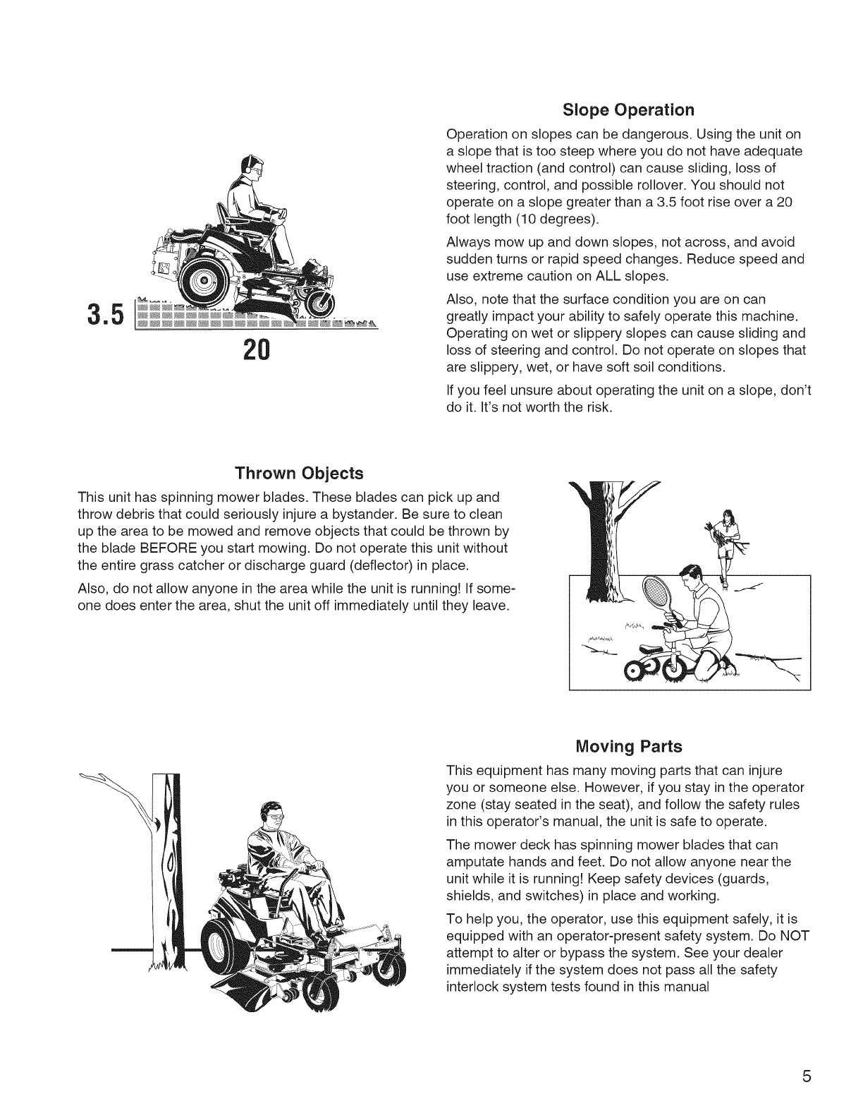
Slope Operation
Operation on slopes can be dangerous. Using the unit on
a slope that is too steep where you do not have adequate
wheel traction (and control) can cause sliding, loss of
steering, control, and possible rollover. You should not
operate on a slope greater than a 3.5 foot rise over a 20
foot length (10 degrees).
Always mow up and down slopes, not across, and avoid
sudden turns or rapid speed changes. Reduce speed and
use extreme caution on ALL slopes.
Also, note that the surface condition you are on can
greatly impact your ability to safely operate this machine.
Operating on wet or slippery slopes can cause sliding and
loss of steering and control. Do not operate on slopes that
are slippery, wet, or have soft soil conditions.
If you feel unsure about operating the unit on a slope, don't
do it. It's not worth the risk.
Thrown Objects
This unit has spinning mower blades. These blades can pick up and
throw debris that could seriously injure a bystander. Be sure to clean
up the area to be mowed and remove objects that could be thrown by
the blade BEFORE you start mowing. Do not operate this unit without
the entire grass catcher or discharge guard (deflector) in place.
Also, do not allow anyone in the area while the unit is running! if some-
one does enter the area, shut the unit off immediately until they leave.
Moving Parts
This equipment has many moving parts that can injure
you or someone else. However, if you stay in the operator
zone (stay seated in the seat), and follow the safety rules
in this operator's manual, the unit is safe to operate.
The mower deck has spinning mower blades that can
amputate hands and feet. Do not allow anyone near the
unit while it is running! Keep safety devices (guards,
shields, and switches) in place and working.
To help you, the operator, use this equipment safely, it is
equipped with an operator-present safety system. Do NOT
attempt to alter or bypass the system. See your dealer
immediately if the system does not pass all the safety
interlock system tests found in this manual
5
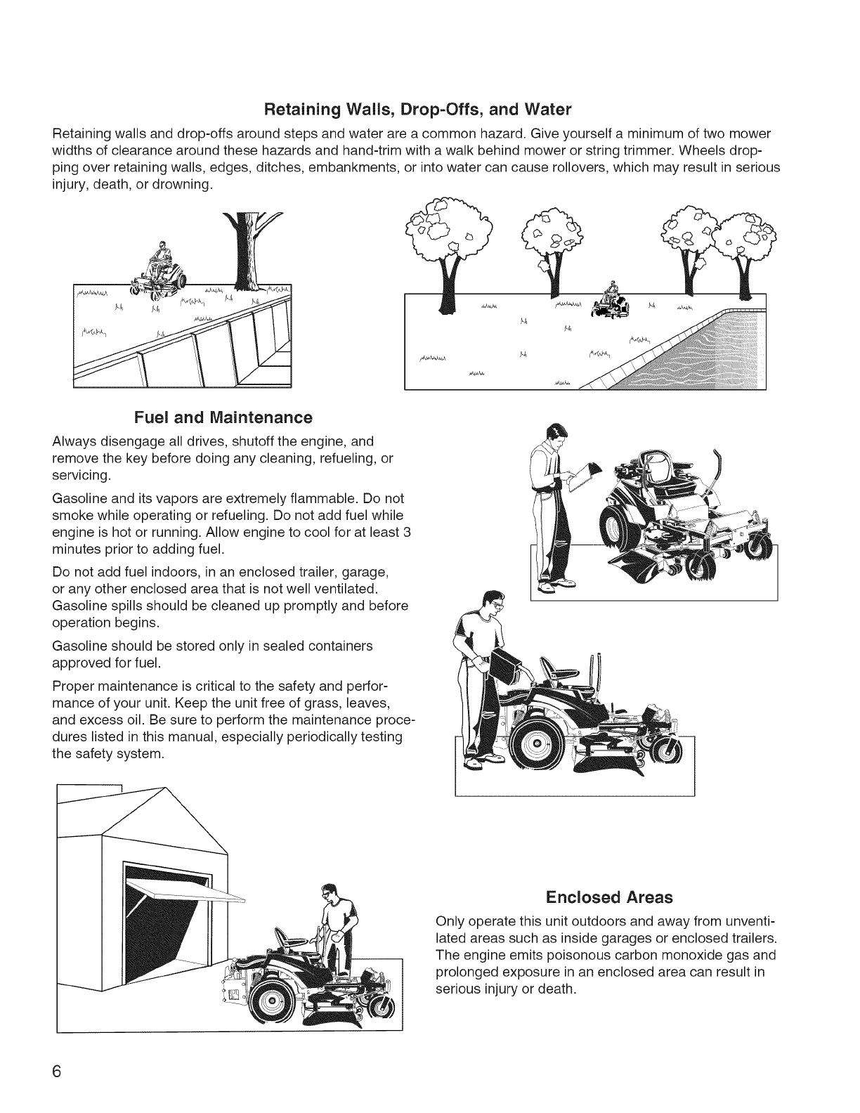
Retaining Wails, Drop-Offs, and Water
Retaining walls and drop-offs around steps and water are a common hazard. Give yourself a minimum of two mower
widths of clearance around these hazards and hand-trim with a walk behind mower or string trimmer. Wheels drop-
ping over retaining walls, edges, ditches, embankments, or into water can cause rollovers, which may result in serious
injury, death, or drowning.
Fuel and Maintenance
Always disengage all drives, shutoff the engine, and
remove the key before doing any cleaning, refueling, or
servicing.
Gasoline and its vapors are extremely flammable. Do not
smoke while operating or refueling. Do not add fuel while
engine is hot or running. Allow engine to cool for at least 3
minutes prior to adding fuel.
Do not add fuel indoors, in an enclosed trailer, garage,
or any other enclosed area that is not well ventilated.
Gasoline spills should be cleaned up promptly and before
operation begins.
Gasoline should be stored only in sealed containers
approved for fuel.
Proper maintenance is critical to the safety and perfor-
mance of your unit. Keep the unit free of grass, leaves,
and excess oil. Be sure to perform the maintenance proce-
dures listed in this manual, especially periodically testing
the safety system.
Enclosed Areas
Only operate this unit outdoors and away from unventi-
lated areas such as inside garages or enclosed trailers.
The engine emits poisonous carbon monoxide gas and
prolonged exposure in an enclosed area can result in
serious injury or death.
6
WARNING: This powerful cutting machine is capable of amputating hands and feet and can throw objects that can
cause injury and damage! Failure to comply with the following SAFETY instructions could result in serious injury or
death to the operator or other persons. The owner of the machine must understand these instructions and must allow
only persons who understand these instructions to operate machine. Each person operating the machine must be of
sound mind and body and must not be under the influence of any substance, which might impair vision, dexterity or
judgment. If you have any questions pertaining to your machine which your dealer cannot answer to your satisfaction,
contact the Customer Service Department.
Protection for Children
Tragic accidents can occur if the operator is not alert to
the presence of children. Children are often attracted to
the machine and the mowing activity. Children who have
been given rides in the past may suddenly appear in the
mowing area for another ride and be run over or backed
over by the machine. Never assume that children will
remain where you last saw them.
1. KEEP children out of the mowing area and under the
watchful care of a responsible adult other than the
operator.
2. DO NOT allow children in yard when machine is
operated (even with the blade OFF).
3. DO NOT allow children or others to ride on machine,
attachments or towed equipment (even with the
blades OFF). They may fall and be seriously injured.
4. DO NOT allow pre-teenage children to operate
machine.
5. ALLOW only responsible adults & teenagers with
mature judgment under close adult supervision to
operate machine.
6. DO NOT operate blades in reverse. STOP BLADES.
LOOK and SEE behind and down for children, pets
and hazards before and while backing.
7. USE EXTRA CARE when approaching blind corners,
shrubs, trees, or other objects that may obscure
vision.
Protection Against Tipovers
Slopes are a major factor related to loss-of-control and
tip-over accidents, which can result in severe injury or
death. All slopes require extra CAUTION. If you cannot
back up the slope or if you feel uneasy on the slope, DO
NOT mow it. Use extra care with grass catchers or other
attachments; these affect the handling and the stability of
the machine.
1. DO NOT operate machine on slopes exceeding 10
degrees (18% grade).
2. Exercise EXTREME CAUTION on all slopes. Turn
blades OFF when traveling uphill. Use a slow speed
and avoid sudden or sharp turns.
3. DO NOT operate machine back and forth across face
of slopes. Operate up and down. Practice on slopes
with blades off.
4. AVOID starting, stopping or turning on slopes. If
machine stops going uphill or tires lose traction, turn
blades OFF and back slowly straight down the slope.
5. STAY ALERT for holes and other hidden hazards.
Tall grass can hide obstacles. Keep away from
ditches, washouts, culverts, fences and protruding
objects.
Protection Against Tipovers
(Continued From Previous Column)
6. KEEP A SAFE DISTANCE (at least 3 feet) away from
edge of ditches and other drop offs. The machine
could turn over if an edge caves in.
7. Always begin forward motion slowly and with caution.
8. Use weights or a weighted load carrier in accordance
with instructions supplied with a grass catcher. DO
NOT operate machine on slopes exceeding 10
degrees (18% grade) when equipped with grass
catcher.
9. DO NOT put your foot on the ground to try to stabilize
the machine.
10. DO NOT operate machine on wet grass. Reduced
traction could cause sliding.
11. Chose a low enough speed setting so that you will not
have to stop or shift on a slope. Tires may lose trac-
tion on slopes even though the brakes are functioning
properly.
12. DO NOT operate machine under any condition where
traction, steering or stability is doubtful.
13. Always keep the machine in gear when going down
slopes. DO NOT shift to neutral (or actuate hydro roll
release) and coast downhill.
Preparation
1. Read, understand, and follow instructions and warn-
ings in this manual and on the machine, engine and
attachments. Know the controls and the proper use of
the machine before starting.
2. Only mature, responsible persons shall operate the
machine and only after proper instruction.
3. Data indicates that operators age 60 and above, are
involved in a large percentage of mower-related inju-
ries. These operators should evaluate their ability to
operate the mower safely enough to protect them-
selves and others from serious injury.
4. Handle fuel with extra care. Fuels are flammable and
vapors are explosive. Use only an approved fuel con-
tainer. DO NOT remove fuel cap or add fuel with
engine running. Add fuel outdoors only with engine
stopped and cool. Clean spilled fuel from machine.
DO NOT smoke.
5. Practice operation of machine with BLADES OFF to
learn controls and develop skills.
7

Preparation
(Continued From Previous Page)
6. Check the area to be mowed and remove all objects
such as toys, wire, rocks, limbs and other objects that
could cause injury if thrown by blade or interfere with
mowing.
7. Keep people and pets out of mowing area. Immed-
iately STOP blades, STOP engine, and STOP
machine if anyone enters the area.
8. Check shields, deflectors, switches, blade controls
and other safety devices frequently for proper opera-
tion and location.
9. Make sure all safety decals are clearly legible.
Replace if damaged.
10. Protect yourself when mowing and wear safety glass-
es, long pants and substantial footwear.
11. Know how to STOP blades and engine quickly in
preparation for emergencies.
12. Use extra care when loading or unloading the
machine into a trailer or truck.
13. Check grass catcher components frequently for signs
of wear or deterioration and replace as needed to
prevent injury from thrown objects going through
weak or worn spots.
Safe Handling of Gasoline
To avoid personal injury or property damage, use
extreme care in handling gasoline. Gasoline is extremely
flammable and the vapors are explosive.
1. Extinguish all cigarettes, cigars, pipes and other
sources of ignition.
2. Use only an approved fuel container.
3. DO NOT remove fuel cap or add fuel with the engine
running. Allow the engine to cool before refueling.
4. DO NOT refuel the machine indoors.
5. DO NOT store the machine or fuel container inside
where there is an open flame, spark or pilot light such
as on a water heater or other appliances.
6. DO NOT fill fuel containers inside a vehicle or on a
truck or trailer bed with a plastic liner. Always place
the containers on the ground away from the vehicle
before filling.
7. Remove gas-powered equipment from the vehicle or
trailer and refuel it on the ground. If this is not pos-
sible, then refuel equipment using a portable con-
tainer, rather than a gasoline dispenser nozzle.
8. DO NOT start gas powered equipment in enclosed
vehicles or trailers.
9. Keep the nozzle in contact with the rim of the fuel
tank or container opening at all times until fueling is
complete. DO NOT use a nozzle lock-open device
10. If fuel is spilled on clothing, change clothing immedi-
ately.
11. Never overfill a fuel tank. Replace fuel cap and tigh-
ten securely.
OPERATION
1. Mount and dismount machine from left side. Keep
clear of discharge opening at all times.
2. Start engine from operator's seat, if possible. Make
sure blades are OFF and parking brake is set.
3. DO NOT leave machine with engine running. STOP
engine, STOP blades, SET brake, and Remove key
before leaving operators position of any reason.
4. DO NOT operate machine unless properly seated
with feet on feet rests or pedal(s).
5. STOP BLADES and ENGINE and make sure blades
have stopped before removing grass catcher or
unclogging mower to prevent loss of fingers or hand.
6. Blades must be OFF except when cutting grass.
Set blades in highest position when mowing over
rough ground.
7. Keep hands and feet away from rotating blades
underneath deck. DO NOT place foot on ground
while BLADES are ON or machine is in motion.
8. DO NOT operate machine without entire grass
catcher or guards in place and working. DO NOT
point discharge at people, passing cars, windows or
doors.
9. Slow down before turning.
10. Watch out for traffic when near or crossing roadways.
11. STOP engine immediately after striking an obstruc-
tion. Inspect machine and repair damage before
resuming operation.
12. Operate machine only in daylight or with good artifi-
cial light.
13. Move joystick (if equipped) SLOWLY to maintain con-
trol during speed and directional changes.
14. Exercise CAUTION when pulling loads. Limit loads
to those you can safely control and attach loads to
hitch plate as specified with attachment instructions.
15. On slopes, the weight of the towed equipment may
cause loss of traction and loss of control. When tow-
ing, travel slowly and allow extra distance to stop.
16. DO NOT operate engine in enclosed areas. Engine
exhaust gases contain carbon monoxide, a deadly
poison.
17. DO NOT discharge material against a wall or obstruc-
tion. Material may ricochet back towards the operator.
18. Only use accessories approved by the manufacturer.
See manufacturer's instructions for proper operation
and installation of accessories.
Emissions
1. Engine exhaust from this product contains chemi-
cals known, in certain quantities, to cause cancer,
birth defects, or other reproductive harm.
2. Look for the relevant Emissions Durability Period and
Air Index information on the engine emissions label.
Ignition System
1. This spark ignition system complies with Canadian
ICES-002.
8
Towing
1. Tow only with a machine that has a hitch designed for
towing. DO NOT attach towed equipment except at
the hitch point.
2. Follow the manufacturer's recommendation for weight
limits for towed equipment and towing on slopes.
3. DO NOT allow children or others on towed equip-
ment.
4. On slopes, the weight of the towed equipment may
cause loss of traction and loss of control.
5. Travel slowly and allow extra distance to stop.
Maintenance
1. DO NOT store machine or fuel container inside where
fumes may reach an open flame, spark or pilot light
such as in a water heater, furnace, clothes dryer or
other gas appliance. Allow engine to cool before
storing machine in an enclosure. Store fuel container
out of the reach of children in a well ventilated, unoc-
cupied building.
2. Keep engine free of grass, leaves or excess grease
to reduce fire hazard and engine overheating.
3. When draining fuel tank, drain fuel into an approved
container outdoors and away from open flame.
4. Check brakes frequently; adjust, repair or replace as
needed.
5. Keep all bolts, nuts and screws properly tight. Check
that all cotter pins are in proper position.
Maintenance
(Continued From Previous Column)
6. Always provide adequate ventilation when running
engine. Exhaust gases contain carbon monoxide, an
odorless and deadly poison.
7. Disconnect negative (black) cable from battery before
performing maintenance or service. Cranking engine
could cause injury.
8. DO NOT work under machine without safety blocks.
9. Service engine and make adjustments only when
engine is stopped. Remove spark plug wire(s) from
spark plug(s) and secure wire(s) away from spark
plug(s).
10. DO NOT change engine governor speed settings or
overspeed engine.
11. Lubricate machine at intervals specified in manual to
prevent controls from binding.
12. Mower blades are sharp and can cut. Wrap the
blades or wear heavy leather gloves and use
CAUTION when handling them.
13. DO NOT test for spark by grounding spark plug next
to spark plug hole; spark plug could ignite gas exiting
engine.
14. Have machine serviced by an authorized dealer at
least once a year and have the dealer install any new
safety devices.
15. Maintain or replace safety and instruction labels as
necessary.
16. Use only genuine replacement parts to assure that
original standards are maintained.
Gr ssWARNING
Catcher bags used on this product are made of
woven fabric, and are subject to deterioration and wear
during normal usage. Check condition of bags before
each use. Immediately replace worn or damaged catch-
er bags with only bags recommended by the manufac-
turer. The Grass Catcher is optional equipment on some
models.
WARNING
Engine exhaust, some of its constituents, and certain
vehicle components contain or emit chemicals known to
the State of California to cause cancer or other repro-
ductive harm.
-| WARNING
Battery posts, terminals and related accessories contain
lead and lead compounds, chemicals known to the
State of California to cause cancer and birth defects or
other reproductive harm. Wash hands after handling.
9
o
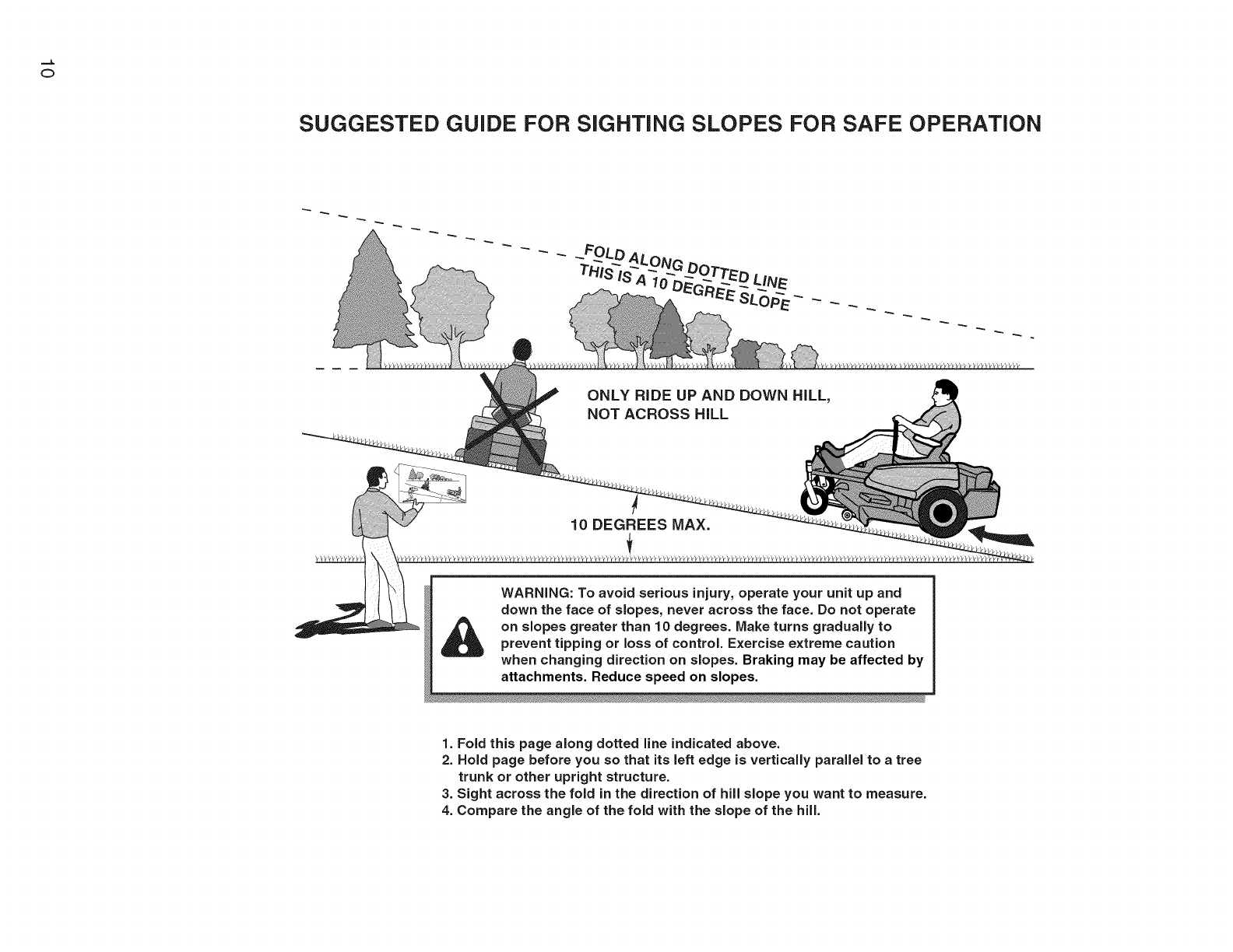
SUGGESTED GUIDE FOR SiGHTiNG SLOPES FOR SAFE OPERATION
ONLY RIDE UP AND DOWN HILL,
NOT ACROSS HILL
10 DEGREES MAX.
WARNING: To avoid serious injury, operate your unit up and
down the face of slopes, never across the face. Do not operate
on slopes greater than 10 degrees. Make turns gradually to
prevent tipping or loss of control. Exercise extreme caution
when changing direction on slopes. Braking may be affected by
attachments. Reduce speed on slopes.
1. Fold this page along dotted line indicated above.
2. Hold page before you so that its left edge is vertically parallel to a tree
trunk or other upright structure.
3. Sight across the fold in the direction of hill slope you want to measure.
4. Compare the angle of the fold with the slope of the hill.
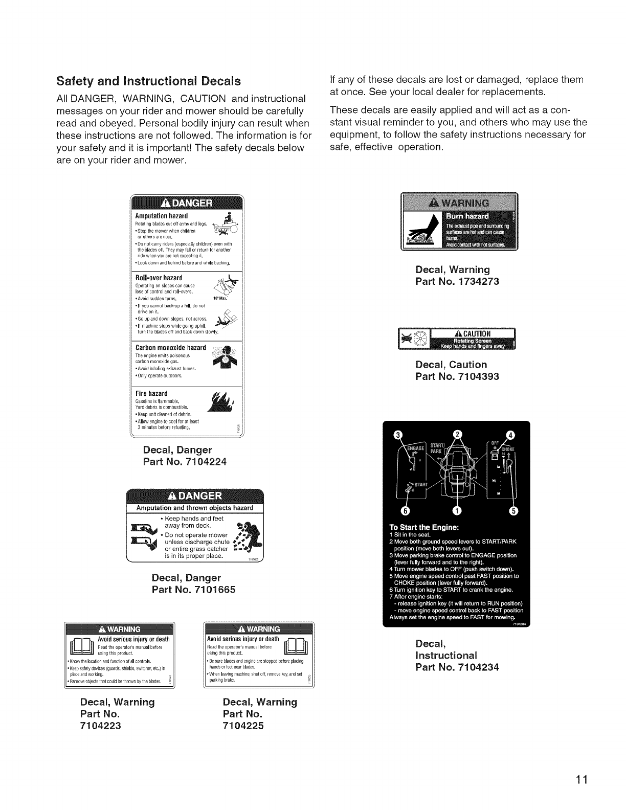
Safety and instructional Decals
All DANGER, WARNING, CAUTION and instructional
messages on your rider and mower should be carefully
read and obeyed. Personal bodily injury can result when
these instructions are not followed. The information is for
your safety and it is important! The safety decals below
are on your rider and mower.
If any of these decals are lost or damaged, replace them
at once. See your local dealer for replacements.
These decals are easily applied and will act as a con-
stant visual reminder to you, and others who may use the
equipment, to follow the safety instructions necessary for
safe, effective operation.
Amputationhazard _,
Relating blades cut off arms and legs.
•Stop the mower when children
or others are nea£
•Do not carry riders (especially children) even with
the blades df. They maylall or return Ior another
ride when you are not expecbng d.
•Look down _nd behind before and while backing.
Roll=overhazard
Operating on slopes can cause
lose of control arid roll-overs.
•Avoid sudden turns.
•If you cannot back-up a hill, do Ilot
drive on it. _>
•Go up and down slopes, not across.
•If machine stops while going uphill,
turn the blades off and back down slowly,
Carbon monoxide hazard . _
The engine emits poisonous
carbor_monoxide gas,
•Avoid inhaling exhaust fumes.
•Only operate outdoors.
Fire hazard
Gasoline is flammable.
Yard debris is combustible.
.Keep unit cleaned of debris.
. Anew engille to cool for at least
3 minutes before refueling,
Decal, Danger
Part No. 7104224
Decal, Warning
Part No. 1734273
CAUTION
Decal, Caution
Part No. 7104393
Amputation and thrown objects_
• Keep hands and feet ]
away from deck. I
"_ •DO not operate mower _#-_,
_ untess discharge chute #.#_,_'J_]
_'_ or entire grass catcher _=_ _,_--/
,, is in its proper place. _0_._
Deca_, Danger
Part No. 7101665
gecal_
Instructional
Part No. 7104234
Decal, Warning
Part No.
7104223
Decal, Warning
Part No.
7104225
11

Decal, Ground
Speed Lever, L.H.
Part No. 7104226
Decal, Ground
Speed Lever, R.H.
Part No. 7104227
Decal, Control Panel,
L.H.
Part No. 7104232
Decal, Control Panel,
R.H.
Part No. 7104233
Safety Interlock System Tests
This unit is equipped with a Safety interlock System.
Do not attempt to bypass or tamper with the switches/
devices.
TEST 1 -- ENGINE SHOULD NOT CRANK IF:
• PTO switch is engaged, OR
Parking brake is disengaged, OR
Ground speed levers are not locked in their START/
PARK positions.
TEST 2-- ENGINE SHOULD CRANK iF:
PTO switch is NOT engaged, AND
Parking brake is engaged, AND
Ground speed levers are locked into their
START/PARK positions.
TEST 3 -- ENGINE SHOULD SHUT OFF iF:
Operator rises off seat with PTO engaged, OR
Operator rises off seat with parking brake dis-
enaged, OR
Operator rises off seat with ground speed levers not
locked in their START/PARK positions.
TEST 4 -- CHECK MOWER BLADE STOPPING TiME
The mower blades and mower drive belt should come
to a complete stop within five seconds after the electric
PTO switch is turned off (or operator rises off seat), if
mower drive belt does not stop within five seconds, see
your dealer.
NOTE: Once the engine has stopped, the PTO switch
must be turned off, the parking brake must be engaged,
and the ground speed levers must be locked in their
START/PARK positions in order to start the engine.
WARNING
If the unit does not pass asafety test, do not
operate it. See an authorized dealer.
Decal, Weight Limit
Part No. 7101940
12
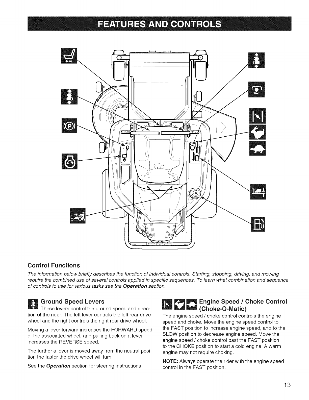
Control Functions
The information below briefly describes the function of individual controls. Starting, stopping, driving, and mowing
require the combined use of several controls applied in specific sequences. To learn what combination and sequence
of controls to use for various tasks see the Operation section.
Ground Speed Levers
These levers control the ground speed and direc-
tion of the rider. The left lever controls the left rear drive
wheel and the right controls the right rear drive wheel.
Moving a lever forward increases the FORWARD speed
of the associated wheel, and pulling back on a lever
increases the REVERSE speed.
The further a lever is moved away from the neutral posi-
tion the faster the drive wheel will turn.
See the Operation section for steering instructions.
_1_ Engine Speed /Choke Control
(Choke-O-IVlatic)
The engine speed /choke control controls the engine
speed and choke. Move the engine speed control to
the FAST position to increase engine speed, and to the
SLOW position to decrease engine speed. Move the
engine speed /choke control past the FAST position
to the CHOKE position to start a cold engine. A warm
engine may not require choking.
NOTE: Always operate the rider with the engine speed
control in the FAST position.
13

ignition Switch
The ignition switch starts and stops the engine; it
has three positions:
_OFF
H RUN
[_START
Stops the engine and shuts off the
electrical system.
Allows the engine to run and powers the
electrical system.
Cranks the engine for starting.
NOTE: Never leave the ignition switch in the RUN posi-
tion with the engine stopped-this drains the battery.
PTO Switch
The PTO (Power Take-Off) switch engages and
disengages the mower blade clutch. To engage the PTO,
pull UP on the switch. Push DOWN to disengage. Note
that the operator must be seated firmly in the rider seat
for the PTO to function.
Transmission Release Levers
The transmission release levers deactivate the
transmissions so that the unit can be pushed by hand
(see Pushing the Unit by Hand).
Seat Adjustment Lever
The seat can be adjusted forward and backward
(see Seat Adjustments).
Fuel Tank Cap
To remove the cap, turn counterclockwise.
Mower Cutting Height Adjustment
Switch
The mower cutting height is adjustable between 1.75"
(4,4 cm) and 4.0" (10,0 cm). See Cutting Height
Adjustment.
Parking Brake
Moving the parking brake lever forward and to the
right engages the parking brake. Moving the lever to the
left and back disengages the brake.
14
General Operating Safety
Before first time operation:
• Be sure to read all information in the Operator
Safety section before attempting to operate this rider
and mower.
Become familiar with all of the controls and how to
stop the unit.
Drive in an open area without mowing to become
accustomed to driving the unit.
WARNING
Never operate on slopes greater than 18 percent
(10°).
Select slow ground speed before driving onto
a slope. Use extra caution when operating on
slopes with a rear-mounted grass catcher.
Mow up and down slopes, not across the face,
use caution when changing directions and DO
NOT START OR STOP ON SLOPE.
,WARNING
Never allow passengers to ride on the unit.
Before leaving the operator's position for any
reason, lock the ground speed levers in the
START/PARK position, engage the parking brake,
disengage the PTO, stop the engine and remove
the key.
To reduce fire hazard, keep the engine, rider and
mower free of grass, leaves and excess grease.
Do not stop or park rider over dry leaves, grass
or combustible materials.
Gasoline is highly flammable and must be
handled with care. Never fill the tank when the
engine is still hot from recent operation. Do not
allow open flame, smoking or matches in the
area. Avoid over-filling and wipe up any spills.
WARNING
If you do not understand how a specific control
functions, or have not yet thoroughly read the
Features and Controls section, do so now. Do
NOT attempt to operate the rider without first
becoming familiar with the location and function
of ALL controls.
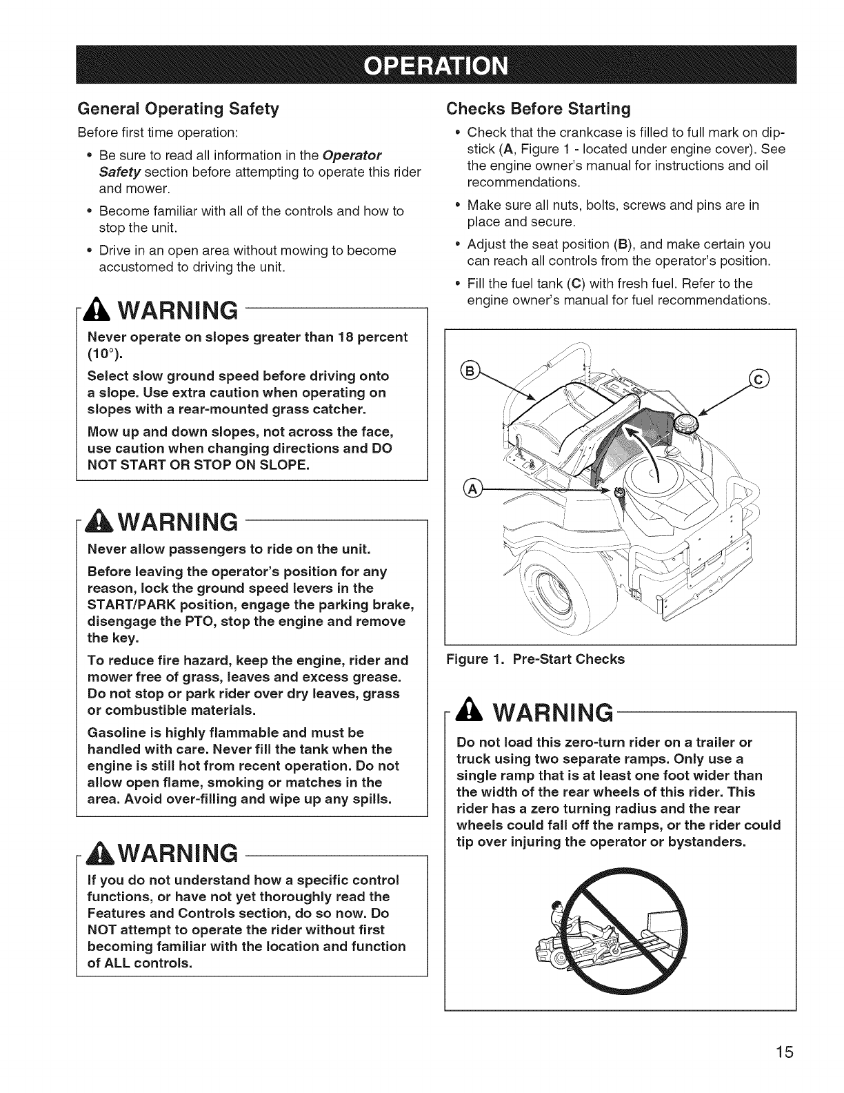
Checks Before Starting
• Check that the crankcase is filled to full mark on dip-
stick (A, Figure 1 - located under engine cover). See
the engine owner's manual for instructions and oil
recommendations.
Make sure all nuts, bolts, screws and pins are in
place and secure.
Adjust the seat position (B), and make certain you
can reach all controls from the operator's position.
Fill the fuel tank (C) with fresh fuel. Refer to the
engine owner's manual for fuel recommendations.
Figure 1. Pro-Start Checks
A WARNING
Do not load this zero-turn rider on a trailer or
truck using two separate ramps. Only use a
single ramp that is at least one foot wider than
the width of the rear wheels of this rider. This
rider has azero turning radius and the rear
wheels could fall off the ramps, or the rider could
tip over injuring the operator or bystanders.
15
Starting the Engine
1. While sitting in the operator's seat, make sure the
PTO switch is disengaged, the parking brake is
engaged, and the ground speed levers are locked in
the START/PARK position.
2. Set the engine speed control to the CHOKE position.
NOTE: A warm engine may not require choking.
3. Insert the key into the ignition switch and turn it to
START.
4. After the engine starts, move the engine speed con-
trol back to the FAST position. Warm up the engine
by running it for at least a minute before engaging the
PTO switch or driving the rider.
5. After warming the engine, ALWAYS operate the
rider at FULL ENGINE SPEED when mowing.
In the event of an emergency the engine can be
stopped by simply turning the ignition switch to
STOP. Use this method only in emergency situations.
For normal engine shut down follow the procedure given
in Stopping the Rider and Engine.
Stopping the Rider and Engine
1. Return the ground speed levers to the middle (or
neutral 'N') position to stop rider movement. Pivot the
levers outward to lock them in the START/PARK posi-
tion.
2. Disengage the PTO by pushing down on the PTO
switch.
3. Engage the parking brake by moving the parking
brake lever forward and to the right.
4. Move the engine speed control to the SLOW position
and turn the ignition key to OFF. Remove the key.
Mowing
1. Make sure the PTO switch is disengaged, the parking
brake is engaged, the ground speed levers are locked
in their START/PARK positions, and the operator is in
the seat.
2. Start the engine (see Starting the Engine).
3. Set the mower cutting height (see Cutting Height
Adjustment).
4. Set the engine speed control to FAST.
5. Disengage the parking brake.
6. Engage the PTO by pulling up on the switch.
7. Pivot the ground speed levers in from the START/
PARK position to the neutral 'N' position.
8. Begin mowing. See Operator Safety for tips on safe
mowing practices.
9. When finished, shut off the PTO.
10. Stop the engine (see Stopping the Rider and
Engine).
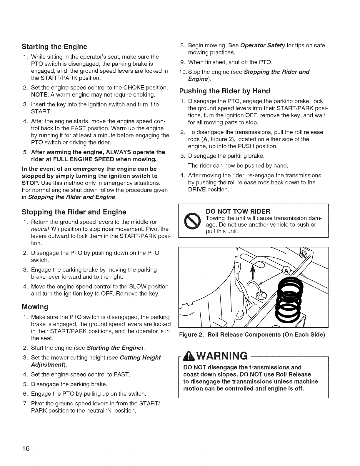
Pushing the Rider by Hand
1. Disengage the PTO, engage the parking brake, lock
the ground speed levers into their START/PARK posi-
tions, turn the ignition OFF, remove the key, and wait
for all moving parts to stop.
2. To disengage the transmissions, pull the roll release
rods (A, Figure 2), located on either side of the
engine, up into the PUSH position.
3. Disengage the parking brake.
The rider can now be pushed by hand.
4. After moving the rider, re-engage the transmissions
by pushing the roll release rods back down to the
DRIVE position.
®DO NOT TOW RIDER
Towing the unit will cause transmission dam-
age. Do not use another vehicle to push or
pull this unit.
Figure 2. Roll Release Components (On Each Side)
WARNING
DO NOT disengage the transmissions and
coast down slopes. DO NOT use Roll Release
to disengage the transmissions unless machine
motion can be controlled and engine is off.
16
Zero Turn
Driving Practice
The ground speed levers of the zero turn rider are
responsive, and learning to gain a smooth and efficient
control of the rider's forward, reverse, and turning move-
ments will take some practice.
Spending some time going through the maneuvers shown
and becoming familiar with how the unit accelerates, trav-
els, and steers -- before you begin mowing -- is abso-
lutely essential to getting the most out of the zero turn
rider.
Locate asmooth, flat area of your lawn -- one with
plenty of room to maneuver. (Clear the area of objects,
people and animals before you begin.) Operate the
unit at mid-engine speed during this practice session
(ALWAYS operate at full engine speed when mowing),
and turn slowly to prevent tire slippage and damage to
your lawn.
We suggest you begin with the Smooth Travel proce-
dure to the right, and then advance through the forward,
reverse, and turning maneuvers.
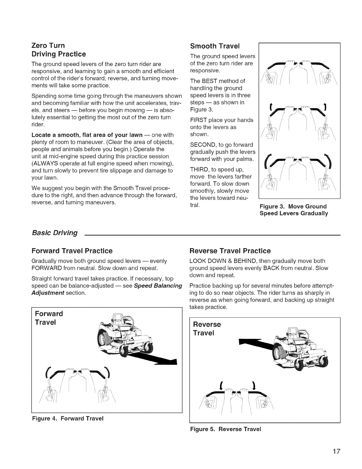
Smooth Travel
The ground speed levers
of the zero turn rider are
responsive.
The BEST method of
handling the ground
speed levers is in three
steps -- as shown in
Figure 3.
FIRST place your hands
onto the levers as
shown.
SECOND, to go forward
gradually push the levers
forward with your palms.
THIRD, to speed up,
move the levers farther
forward. To slow down
smoothly, slowly move
the levers toward neu-
tral. Figure 3. Move Ground
Speed Levers Gradually
Basic Driving
Forward Travel Practice
Gradually move both ground speed levers -- evenly
FORWARD from neutral. Slow down and repeat.
Straight forward travel takes practice. If necessary, top
speed can be balance=adjusted -- see Speed Balancing
Adjustment section.
Forward
Travel
Figure 4. Forward Travel
Reverse Travel Practice
LOOK DOWN & BEHIND, then gradually move both
ground speed levers evenly BACK from neutral. Slow
down and repeat.
Practice backing up for several minutes before attempt-
ing to do so near objects. The rider turns as sharply in
reverse as when going forward, and backing up straight
takes practice.
Reverse
Travel
Figure 5. Reverse Travel
17
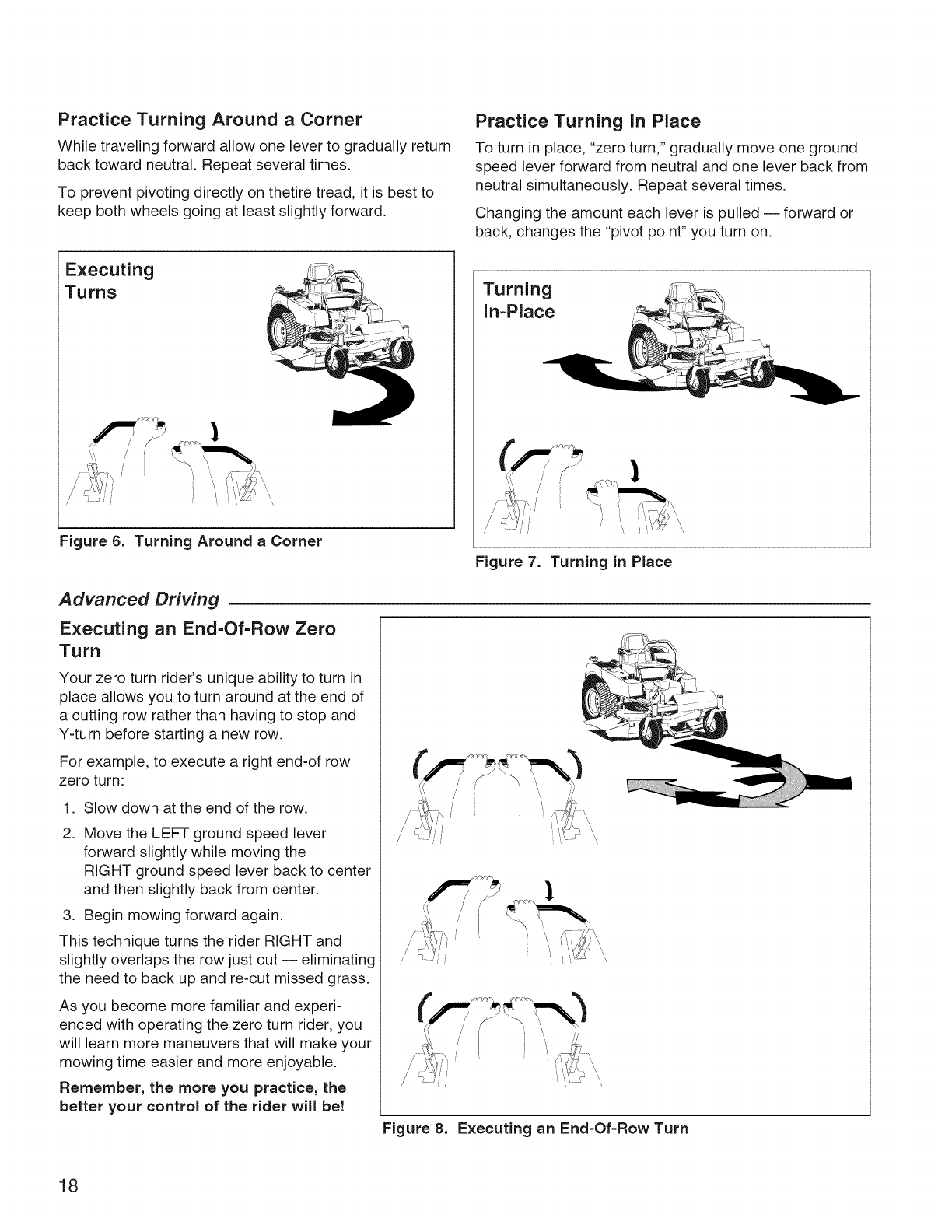
Practice Turning Around a Corner
While traveling forward allow one lever to gradually return
back toward neutral. Repeat several times.
To prevent pivoting directly on thetire tread, it is best to
keep both wheels going at least slightly forward.
Practice Turning in Place
To turn in place, "zero turn," gradually move one ground
speed lever forward from neutral and one lever back from
neutral simultaneously. Repeat several times.
Changing the amount each lever is pulled -- forward or
back, changes the "pivot point" you turn on.
Executing
Turns
Figure 6. Turning Around aCorner
Turning
In-Place
Figure 7. Turning in Place
Advanced Driving
Executing an End=Of-Row Zero
Turn
Your zero turn rider's unique ability to turn in
place allows you to turn around at the end of
a cutting row rather than having to stop and
Y-turn before starting a new row.
For example, to execute a right end-of row
zero turn:
.
2.
Slow down at the end of the row.
Move the LEFT ground speed lever
forward slightly while moving the
RIGHT ground speed lever back to center
and then slightly back from center.
3. Begin mowing forward again.
This technique turns the rider RIGHT and
slightly overlaps the row just cut -- eliminating
the need to back up and re-cut missed grass.
As you become more familiar and experi-
enced with operating the zero turn rider, you
will learn more maneuvers that will make your
mowing time easier and more enjoyable.
Remember, the more you practice, the
better your control of the rider will be!
Figure 8. Executing an End=Of-Row Turn
18
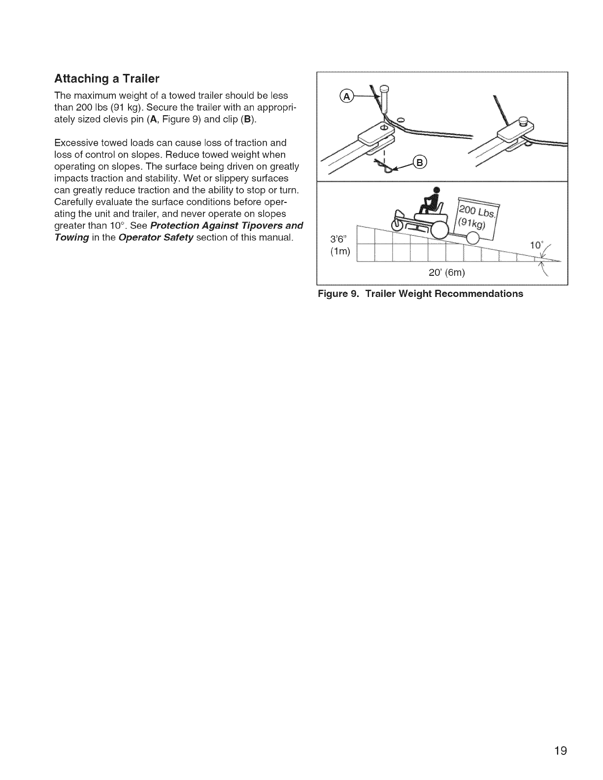
Attaching a Trailer
The maximum weight of a towed trailer should be less
than 200 Ibs (91 kg). Secure the trailer with an appropri-
ately sized clevis pin (A, Figure 9) and clip (B).
Excessive towed loads can cause loss of traction and
loss of control on slopes. Reduce towed weight when
operating on slopes. The surface being driven on greatly
impacts traction and stability. Wet or slippery surfaces
can greatly reduce traction and the ability to stop or turn.
Carefully evaluate the surface conditions before oper-
ating the unit and trailer, and never operate on slopes
greater than 10°. See Protection Against Tipovers and
Towing in the Operator Safety section of this manual. '6"
(lm)
Figure 9.
20' (6m)
Trailer Weight Recommendations
19
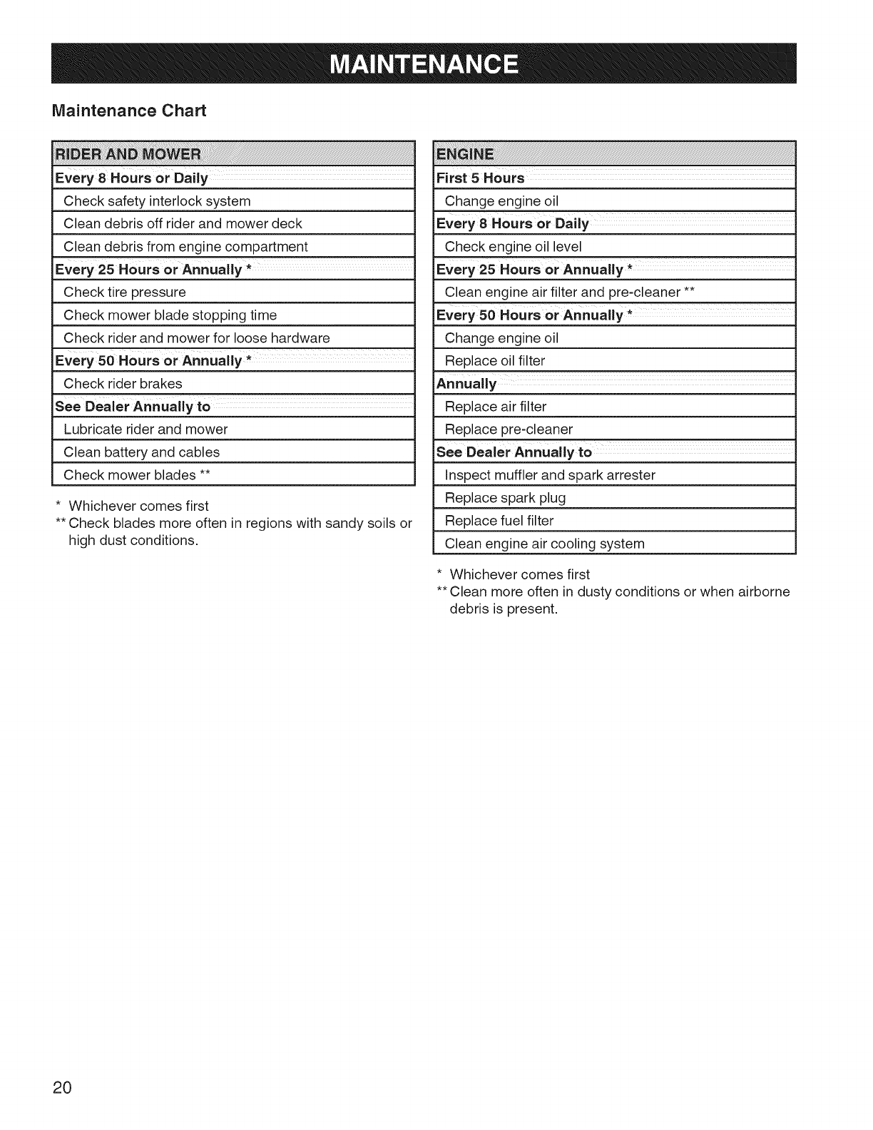
Maintenance Chart
i! ii i ! i i i i i i ! i ! i !i ! i ! i iii i iii iii i iiiii ii iiiiiiiiiiiiiiiiiiiiiiiiiiiiiiiii!i i!iiiiiii ii iii ii iiiiiiiiiiiiiiiiiiiiiiiiiiiiiiiiiiiiiiiiiiiiiiiiiiiiiiiiiiiiiiiiiiiiiiiiiiiiiiiiiiiiiiiiiiiiiiiiiiiiiiiiiiiiiiiiiiiiiiiiiiiiiiiiiiiiiiiiiiiiiiiiiiiiiiiiiiiiiiiiiiiiiiiiiiiiiiiiiiiiiiiiiiiiiiiiiiiiiiiiiiiiiiiiiiiiiiiiiiiiiiiiiiiiiiiiiiiiiiiiiiiiiiiiiiiiiiiiiiiiiiiiiiiiiiiiiiiiiiiiiiiiiiiiiiiiiiiiiiiiiiiiiiiiiiiiiiiiiiiiiiiiiiiiiiiiiiiiiiiiiiiiiiiiiiiiiiiiiiiiiiiiiiiiiiiiiiiiiiiiiiiiiiiiiiiiiiiiiiiiiiiiiiiiiiiiiiiiiiiiiiiiiiiiiiiiiiiiiiii
Every 8 Hours or Dally
Check safety interlock system
Clean debris off rider and mower deck
Clean debris from engine compartment
Every 25 Hours or Annually *
Check tire pressure
Check mower blade stopping time
Check rider and mower for loose hardware
Every 50 Hours or Annually *
Check rider brakes
See Dealer Annually to
Lubricate rider and mower
Clean battery and cables
Check mower blades **
* Whichever comes first
** Check blades more often in regions with sandy soils or
high dust conditions.
i i ! !!! !!iii!i ii ! !!i i ii iiiiiiiiiiiiiiiiiiiiiiiiiiiiiiiiiiiiiiiiiiiiiiiiiiiiiiiiiiiiii!iiiiiiiiiiiiiiiiiiiiiiiiiiiiiiiiiiiiiiiiiiiiiiiiiiiiiiiiiiiiiiiiiiiiiiiiiiiiiiiiiiiiiiiiiiiiiiiiiiiiiiiiiiiiiiiiiiiiiiiiiiiii.........................................iii
First 5Hours
Change engine oil
Every 8 Hours or Daily ..............
Check engine oil level
Every 25 Hours or Annually *
Clean engine air filter and pre-cleaner **
Every 50 Hours or Annually *
Change engine oil
Replace oil filter
Annually
Replace air filter
Replace pre-cleaner
See Dealer Annually t0
Inspect muffler and spark arrester
Replace spark plug
Replace fuel filter
Clean engine air cooling system
* Whichever comes first
**Clean more often in dusty conditions or when airborne
debris is present.
20
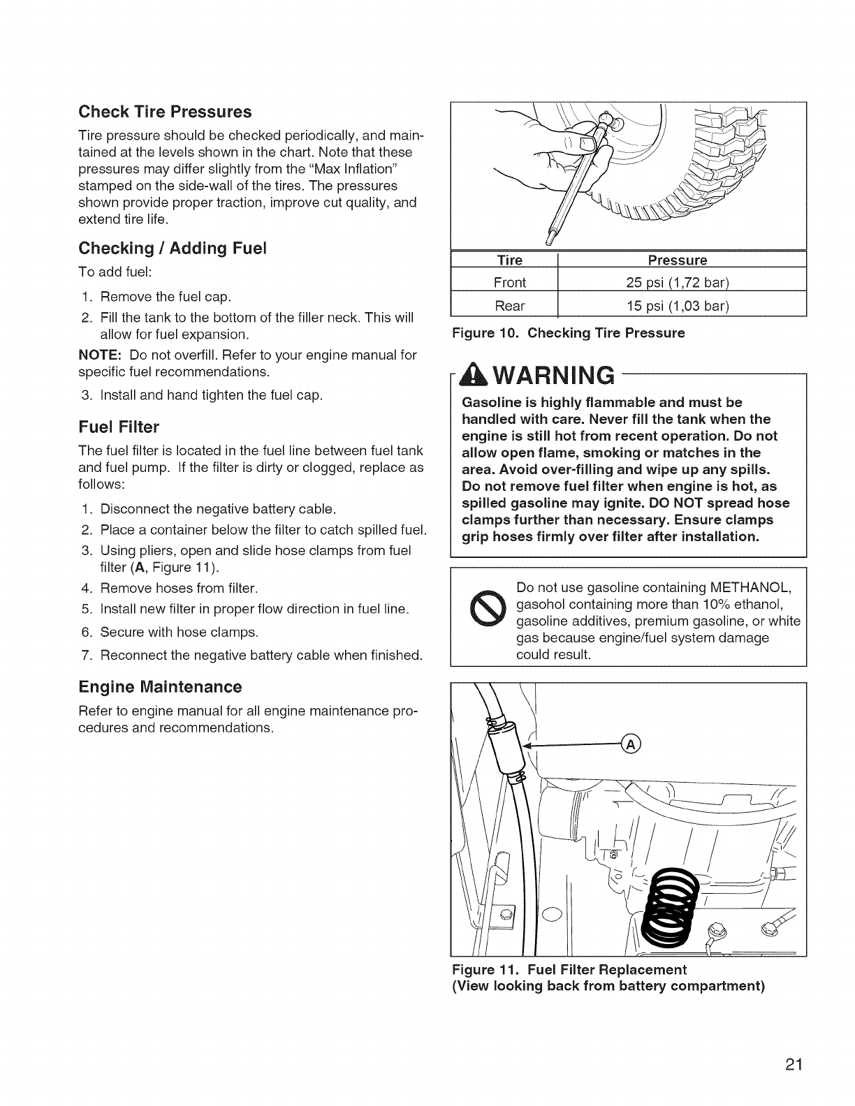
Check Tire Pressures
Tire pressure should be checked periodically, and main-
tained at the levels shown in the chart. Note that these
pressures may differ slightly from the "Max Inflation"
stamped on the side-wall of the tires. The pressures
shown provide proper traction, improve cut quality, and
extend tire life.
Checking /Adding Fuel
To add fuel:
1. Remove the fuel cap.
2. Fill the tank to the bottom of the filler neck. This will
allow for fuel expansion.
NOTE: Do not overfill. Refer to your engine manual for
specific fuel recommendations.
3. Install and hand tighten the fuel cap.
Fuel Filter
The fuel filter is located in the fuel line between fuel tank
and fuel pump. If the filter is dirty or clogged, replace as
follows:
1. Disconnect the negative battery cable.
2. Place a container below the filter to catch spilled fuel.
3. Using pliers, open and slide hose clamps from fuel
filter (A, Figure 11).
4. Remove hoses from filter.
5. Install new filter in proper flow direction in fuel line.
6. Secure with hose clamps.
7. Reconnect the negative battery cable when finished.
Engine Maintenance
Refer to engine manual for all engine maintenance pro-
cedures and recommendations.
Tire Pressure
Front 25 psi (1,72 bar)
Rear 15 psi (1,03 bar)
Figure 10. Checking Tire Pressure
AWARNING
Gasoline is highly flammable and must be
handled with care. Never fill the tank when the
engine is still hot from recent operation. Do not
allow open flame, smoking or matches in the
area. Avoid over-filling and wipe up any spills.
Do not remove fuel filter when engine is hot, as
spilled gasoline may ignite. DO NOT spread hose
clamps further than necessary. Ensure clamps
grip hoses firmly over filter after installation.
®Do not use gasoline containing METHANOL,
gasohol containing more than 10% ethanol,
gasoline additives, premium gasoline, or white
gas because engine/fuel system damage
could result.
®
Figure 11. Fuel Filter Replacement
(View looking back from battery compartment)
21
,WARNING
Before running the mower, make sure the hose
is properly connected and does not come into
cotact with the blades. When the mower is
running and the blades are engaged, the person
cleaning the mower must be in the operator
position, and there must be no bystanders.
Failure to follow these precautions may result in
serious injury or death.
Storage
Before you store your unit for the off-season, read the
Maintenance and Storage instructions in the Operator
Safety section, then perform the following steps:
•Disengage the PTO, move the ground speed levers
into the START/PARK positions, set the parking
brake, & remove the key.
•Perform engine maintenance and storage measures
listed in the engine owner's manual. This includes
draining the fuel system, or adding stabilizer to the
fuel (do not store a fueled unit in an enclosed struc-
ture - see warning).
• Battery life will be increased if it is removed, put in a
cool, dry place and fully charged about once a month.
If the battery is left in the unit, disconnect the negative
cable.
Before starting the unit after it has been stored:
Check all fluid levels. Check all maintenance items.
Perform all recommended checks and procedures
found in the engine owner's manual.
Allow the engine to warm up for several minutes
before use.
WARNING
Never store the unit (with fuel) in an enclosed,
poorly ventilated structure. Fuel vapors can
travel to an ignition source (such as a furnace,
water heater, etc.) and cause an explosion.
Fuel vapor is also toxic to humans and animals.
22
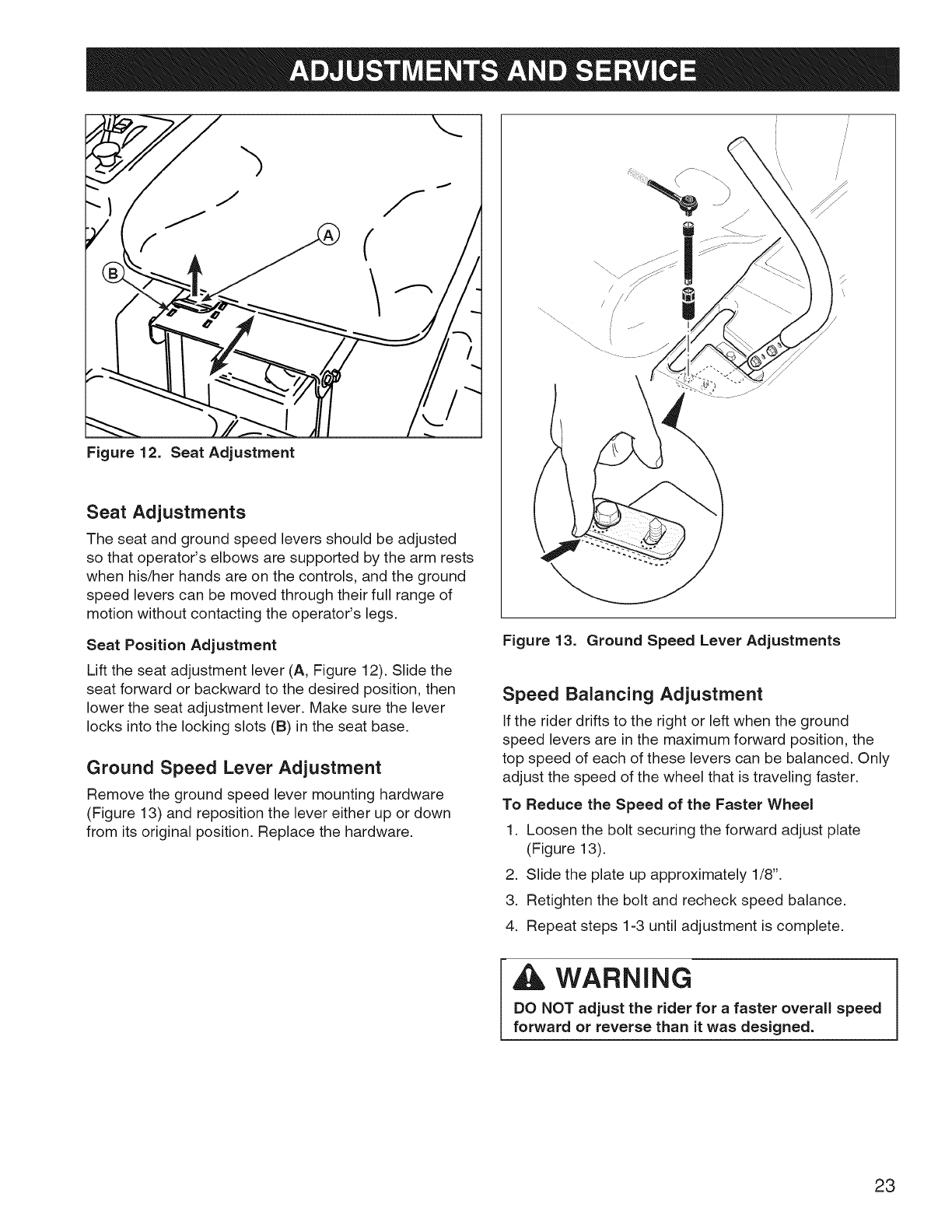
Figure 12. Seat Adjustment
Seat Adjustments
The seat and ground speed levers should be adjusted
so that operator's elbows are supported by the arm rests
when his/her hands are on the controls, and the ground
speed levers can be moved through their full range of
motion without contacting the operator's legs.
Seat Position Adjustment
Lift the seat adjustment lever (A, Figure 12). Slide the
seat forward or backward to the desired position, then
lower the seat adjustment lever. Make sure the lever
locks into the locking slots (B) in the seat base.
Ground Speed Lever Adjustment
Remove the ground speed lever mounting hardware
(Figure 13) and reposition the lever either up or down
from its original position. Replace the hardware.
i
i
\,
/
\
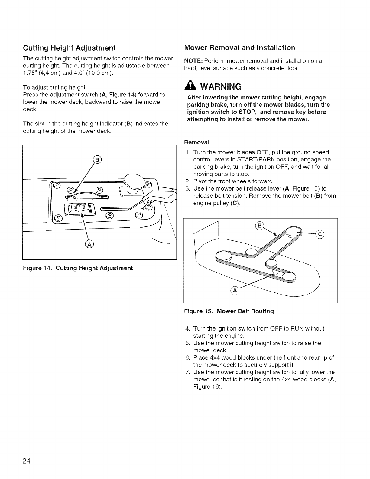
Figure 13. Ground Speed Lever Adjustments
Speed Balancing Adjustment
if the rider drifts to the right or left when the ground
speed levers are in the maximum forward position, the
top speed of each of these levers can be balanced. Only
adjust the speed of the wheel that is traveling faster.
To Reduce the Speed of the Faster Wheel
1. Loosen the bolt securing the forward adjust plate
(Figure 13).
2. Slide the plate up approximately 1/8".
3. Retighten the bolt and recheck speed balance.
4. Repeat steps 1-3 until adjustment is complete.
A WARNING
DO NOT adjust the rider for a faster overall speed
forward or reverse than it was designed.
23
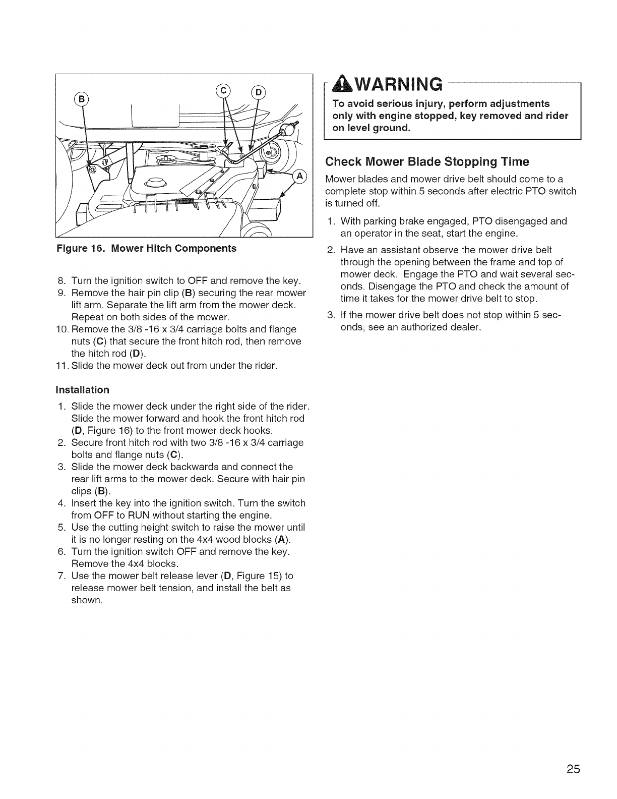
Cutting Height Adjustment
The cutting height adjustment switch controls the mower
cutting height. The cutting height is adjustable between
1.75" (4,4 cm) and 4.0" (10,0 cm).
To adjust cutting height:
Press the adjustment switch (A, Figure 14) forward to
lower the mower deck, backward to raise the mower
deck.
The slot in the cutting height indicator (B) indicates the
cutting height of the mower deck.
Mower Removal and installation
NOTE: Perform mower removal and installation on a
hard, level surface such as a concrete floor.
WARNING
After lowering the mower cutting height, engage
parking brake, turn off the mower blades, turn the
ignition switch to STOP, and remove key before
attempting to install or remove the mower.
Removal
1. Turn the mower blades OFF, put the ground speed
control levers in START/PARK position, engage the
parking brake, turn the ignition OFF, and wait for all
moving parts to stop.
2. Pivot the front wheels forward.
3. Use the mower belt release lever (A, Figure 15) to
release belt tension. Remove the mower belt (B) from
engine pulley (C).
Figure 14. Cutting Height Adjustment
Figure 15. Mower Belt Routing
4. Turn the ignition switch from OFF to RUN without
starting the engine.
5. Use the mower cutting height switch to raise the
mower deck.
6. Place 4x4 wood blocks under the front and rear lip of
the mower deck to securely support it.
7. Use the mower cutting height switch to fully lower the
mower so that is it resting on the 4x4 wood blocks (A,
Figure 16).
24
WARNING
To avoid serious injury, perform adjustments
only with engine stopped, key removed and rider
on level ground.
Figure 16. Mower Hitch Components
8. Turn the ignition switch to OFF and remove the key.
9. Remove the hair pin clip (B) securing the rear mower
lift arm. Separate the lift arm from the mower deck.
Repeat on both sides of the mower.
10. Remove the 3/8 -16 x 3/4 carriage bolts and flange
nuts (C) that secure the front hitch rod, then remove
the hitch rod (D).
11. Slide the mower deck out from under the rider.
Installation
1. Slide the mower deck under the right side of the rider.
Slide the mower forward and hook the front hitch rod
(D, Figure 16) to the front mower deck hooks.
2. Secure front hitch rod with two 3/8 -16 x 3/4 carriage
bolts and flange nuts (C).
3. Slide the mower deck backwards and connect the
rear lift arms to the mower deck. Secure with hair pin
clips (B).
4. Insert the key into the ignition switch. Turn the switch
from OFF to RUN without starting the engine.
5. Use the cutting height switch to raise the mower until
it is no longer resting on the 4x4 wood blocks (A).
6. Turn the ignition switch OFF and remove the key.
Remove the 4x4 blocks.
7. Use the mower belt release lever (D, Figure 15) to
release mower belt tension, and install the belt as
shown.
Check Mower Blade Stopping Time
Mower blades and mower drive belt should come to a
complete stop within 5 seconds after electric PTO switch
is turned off.
1. With parking brake engaged, PTO disengaged and
an operator in the seat, start the engine.
2. Have an assistant observe the mower drive belt
through the opening between the frame and top of
mower deck. Engage the PTO and wait several sec-
onds. Disengage the PTO and check the amount of
time it takes for the mower drive belt to stop.
3. If the mower drive belt does not stop within 5 sec-
onds, see an authorized dealer.
25
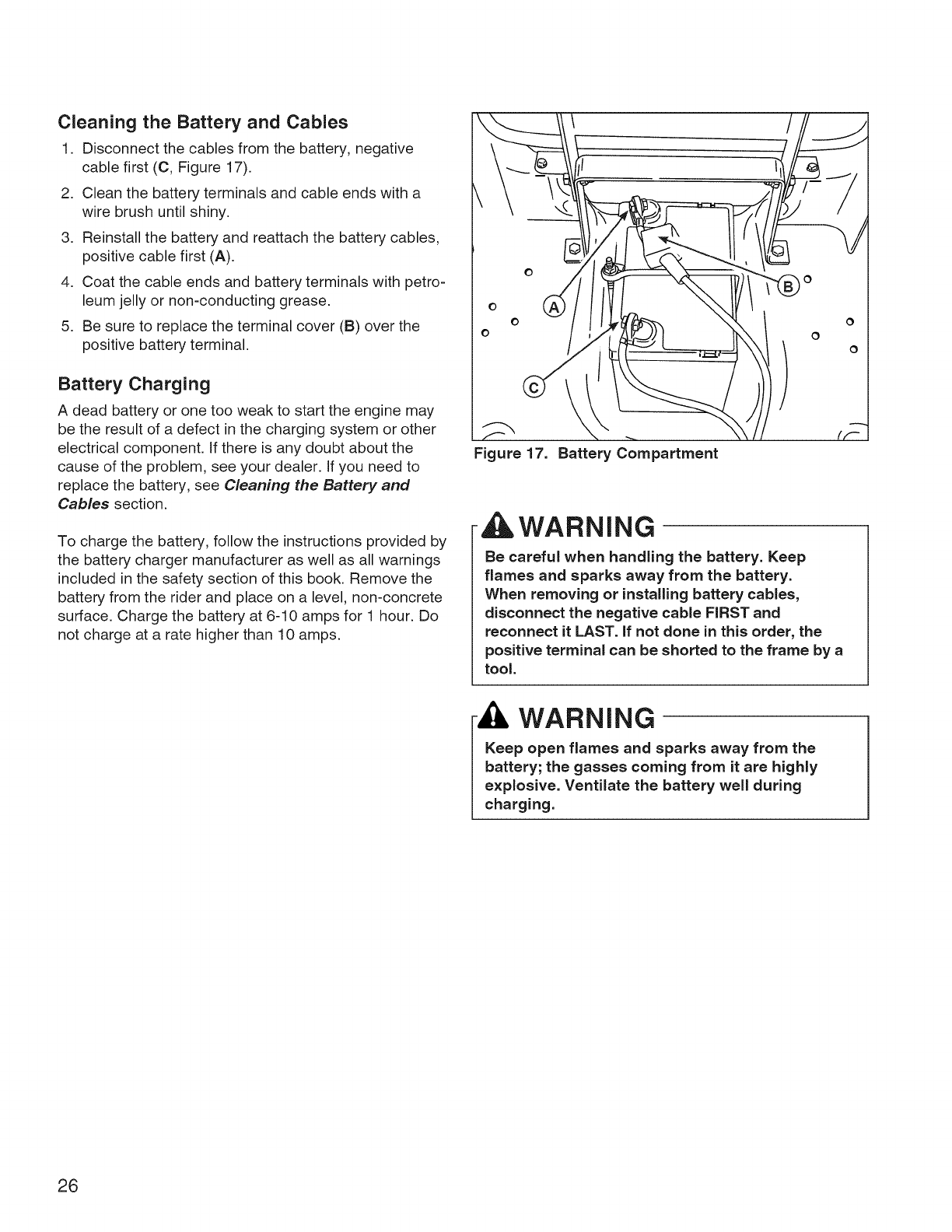
Cleaning the Battery and Cables
1. Disconnect the cables from the battery, negative
cable first (C, Figure 17).
2. Clean the battery terminals and cable ends with a
wire brush until shiny.
3. Reinstall the battery and reattach the battery cables,
positive cable first (A).
4. Coat the cable ends and battery terminals with petro-
leum jelly or non-conducting grease.
5. Be sure to replace the terminal cover (B) over the
positive battery terminal.
Battery Charging
A dead battery or one too weak to start the engine may
be the result of a defect in the charging system or other
electrical component, if there is any doubt about the
cause of the problem, see your dealer. If you need to
replace the battery, see Cleaning the Battery and
Cables section.
To charge the battery, follow the instructions provided by
the battery charger manufacturer as well as all warnings
included in the safety section of this book. Remove the
battery from the rider and place on a level, non-concrete
surface. Charge the battery at 6-10 amps for 1 hour. Do
not charge at a rate higher than 10 amps.
Figure 17. Battery Compartment
WARNING
Be careful when handling the battery. Keep
flames and sparks away from the battery.
When removing or installing battery cables,
disconnect the negative cable FIRST and
reconnect it LAST. if not done in this order, the
positive terminal can be shorted to the frame by a
tool.
WARNING
Keep open flames and sparks away from the
battery; the gasses coming from it are highly
explosive. Ventilate the battery well during
charging.
26
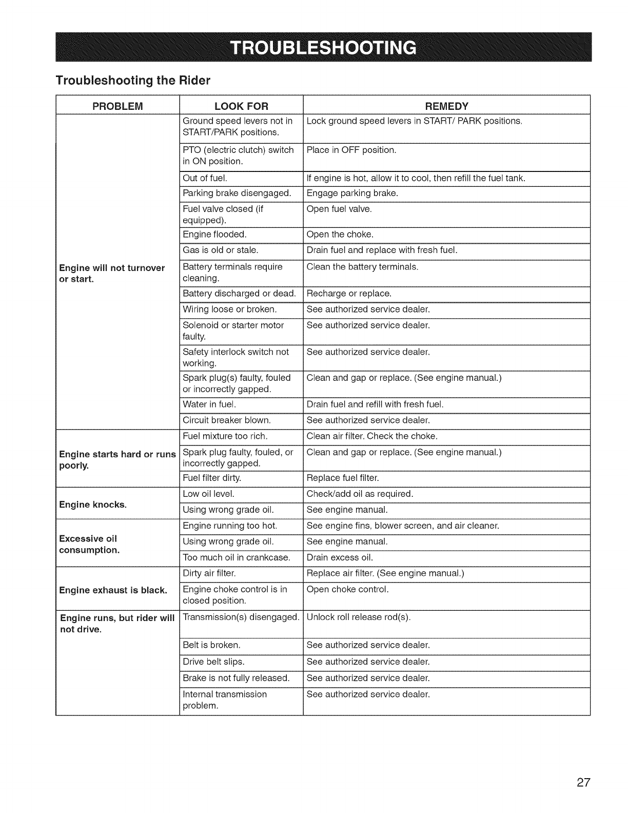
Troubleshooting the Rider
PROBLEM LOOK FOR REMEDY
Ground speed levers not in Lock ground speed levers in START/PARK positions.
START/PARK positions,
PTO (electric clutch) switch Place in OFF position.
in ON position.
Out of fuel. If engine is hot, allow it to cool, then refill the fuel tank.
Parking brake disengaged. Engage parking brake.
Fuel valve closed (if Open fuel valve.
equipped).
Engine flooded. Open the choke.
Gas is old or stale. Drain fuel and replace with fresh fuel.
Engine will not turnover Battery terminals require Clean the battery terminals.
or start, cleaning.
Battery discharged or dead. Recharge or replace.
Wiring loose or broken. See authorized service dealer.
Solenoid or starter motor See authorized service dealer.
faulty.
Safety interlock switch not See authorized service dealer.
working.
Spark plug(s) faulty, fouled Clean and gap or replace. (See engine manual.)
or incorrectly gapped.
Water in fuel. Drain fuel and refill with fresh fuel.
Circuit breaker blown. See authorized service dealer.
Fuel mixture too rich. Clean air filter. Check the choke.
Engine starts hard or runs Spark plug faulty, fouled, or Clean and gap or replace. (See engine manual.)
poorly, incorrectly gapped.
Fuel filter dirty. Replace fuel filter.
Low oil level. ChecWadd oil as required.
Engine knocks. Using wrong grade oil. See engine manual.
Engine running too hot. See engine fins, blower screen, and air cleaner.
Excessive oil Using wrong grade oil. See engine manual.
consumption. Too much oil in crankcase. Drain excess oil.
Dirty air filter. Replace air filter. (See engine manual.)
Engine exhaust is black. Engine choke control is in Open choke control.
closed position.
Engine runs, but rider will Transmission(s) disengaged. Unlock roll release rod(s).
not drive.
Belt is broken. See authorized service dealer.
Drive belt slips. See authorized service dealer.
Brake is not fully released. See authorized service dealer.
Internal transmission See authorized service dealer.
problem.
27
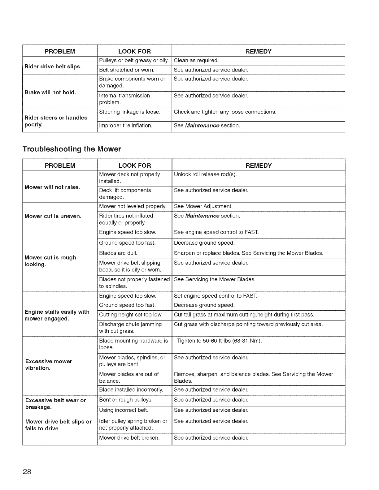
PROBLEM LOOK FOR REMEDY
Pulleys or belt greasy or oily. Clean as required.
iRider drive belt slips. Belt stretched or worn. See authorized service dealer.
Brake components worn or See authorized service dealer.
damaged.
Brake will not hold. Internal transmission See authorized service dealer.
problem.
Steering linkage is loose. Check and tighten any loose connections.
Rider steers or handles
poorly. Improper tire inflation. See Maintenance section.
Troubleshooting the Mower
PROBLEM LOOK FOR REMEDY
Mower deck not properly Unlock roll release rod(s).
installed.
Mower will not raise. Deck lift components See authorized service dealer.
damaged.
Mower not leveled properly. See Mower Adjustment.
Mower cut is uneven. Rider tires not inflated See Maintenance section.
equally or properly.
Engine speed too slow. See engine speed control to FAST.
Ground speed too fast. Decrease ground speed.
Blades are dull. Sharpen or replace blades. See Servicing the Mower Blades.
Mower cut is rough
looking. Mower drive belt slipping See authorized service dealer.
because it is oily or worn.
Blades not properly fastened See Servicing the Mower Blades.
to spindles.
Engine speed too slow. Set engine speed control to FAST.
Ground speed too fast. Decrease ground speed.
Engine stalls easily with Cutting height set too low. Cut tall grass at maximum cutting.height during first pass.
i mower engaged. Discharge chute jamming Cut grass with discharge pointing toward previously cut area.
with cut grass.
Blade mounting hardware is Tighten to 50-60 ft-lbs (68-81 Nm).
loose.
Mower blades, spindles, or See authorized service dealer.
Excessive mower
vibration, pulleys are bent.
Mower blades are out of Remove, sharpen, and balance blades. See Servicing the Mower
balance. Blades.
Blade installed incorrectly. See authorized service dealer.
Excessive belt wear or Bent or rough pulleys. See authorized service dealer.
breakage. Using incorrect belt. See authorized service dealer.
Mower drive belt slips or Idler pulley spring broken or See authorized service dealer.
fails to drive, not properly attached.
Mower drive belt broken. See authorized service dealer.
28

Engine:
21 HP Briggs & Stratton
Transmissions:
Make
Make Briggs & Stratton® Model
Model Platinum Series TM, Single
Horsepower 21 @ 3500 rpm Type
Displacement 32.95 cu in. (540 cc) Hydraulic Fluid
Electrical System Battery 12 Volt, 230 CCA Speeds
Alternator 9 amp @ Specified rpm
48 oz (1,4 L) w/FilterOil Capacity
Hydro Gear
ZC-AUBB-2ADB-1DPX (LH)
ZC-DUBB-2ADC-1DPX (RH)
EZT
Sealed Unit
Forward: 0-6 MPH (0-9.66 km/h)
Reverse: 0-3 MPH (0-4.83 km/h)
Front Wheels
Dimensions:
Chassis: Overall Length 75" (191 cm)
Fuel Tank Capacity: 3.0 Gallons (11,4 L) Overall Width 54" (137 cm)
Rear Wheels Tire Size: 18 x 8.50-8 Height 39" (99 cm)
Inflation Pressure: 15 psi (1,03 bar) Weight (approx.) 604 Ibs (274 kg)
Tire Size: 11 x 4.00-5
Inflation Pressure: 25 psi (1,72 bar)
Parts and Accessories
See an authorized dealer.
Engine Power Rating information
The gross power rating for individual gas engine models is labeled in accordance with SAE (Society of Automotive
Engineers) code J1940 (Small Engine Power & Torque Rating Procedure), and rating performance has been obtained
and corrected in accordance with SAE J1995 (Revision 2002-05). Torque values are derived at 3060 RPM; horsepow-
er values are derived at 3600 RPM. Actual gross engine power will be lower and is affected by, among other things,
ambient operating conditions and engine-to-engine variability. Given both the wide array of products on which engines
are placed and the variety of environmental issues applicable to operating the equipment, the gas engine will not
develop the rated gross power when used in a given piece of power equipment (actual "on-site" or net horsepower).
This difference is due to a variety of factors including, but not limited to, accessories (air cleaner, exhaust, charging,
cooling, carburetor, fuel pump, etc.), application limitations, ambient operating conditions (temperature, humidity, alti-
tude), and engine-to-engine variability. Due to manufacturing and capacity limitations, Briggs & Stratton may substitute
an engine of higher rated power for this Series engine.
29

CRAFTSMAN TWO YEAR FULL WARRANTY
FOR TWO YEARS from the date of purchase, if any non-expendable part of this riding equipment fails due
to a defect in material or workmanship, visit www.craftsman.com or call 1-800-659-5917 to arrange for free
in-home repair.
The frame and front axle will be repaired free of charge for five years from the date of purchase if defective in
material or workmanship.
In all cases, if repair proves impossible, the riding equipment will be replaced free of charge with the same or
an equivalent model.
The battery will be replaced free of charge for 90 days from the date of purchase if defective in material or
workmanship (our testing proves that it will not hold a charge).
This warranty is void if this product is ever used while providing commercial services or if rented to another
person.
This warranty covers ONLY defects in material and workmanship. Warranty coverage does NOT
include:
•Expendable items that can wear out from normal use within the warranty period, including but not limited
to blades, spark plugs, air cleaners, belts, and oil filters.
•Standard maintenance servicing, oil changes, or tune-ups.
•Tire replacement or repair caused by punctures from outside objects, such as nails, thorns, stumps, or
glass.
•Tire or wheel replacement or repair resulting from normal wear, accident, or improper operation or
maintenance.
Repairs necessary because of operator abuse, including but not limited to damage caused by towing
objects beyond the capability of the riding equipment, impacting objects that bend the frame or crank-
shaft, or over-speeding the engine.
Repairs necessary because of operator negligence, including but not limited to, electrical and mechani-
cal damage caused by improper storage, failure to use the proper grade and amount of engine oil, failure
to keep the deck clear of flammable debris, or failure to maintain the riding equipment according to the
instructions contained in the operator's manual.
•Engine (fuel system) cleaning or repairs caused by fuel determined to be contaminated or oxidized
(stale). In general, fuel should be used within 30 days of its purchase date.
•Normal deterioration and wear of the exterior finishes, or product label replacement.
This warranty gives you specific legal rights, and you may also have other rights which vary from state to
state.
Sears Brands Management Corporation, Hoffman Estates, IL 60179
30

Congratulations on making a smart purchase.
Your new Craftsman® product is designed and
manufactured for years of dependable operation. But
like all products, it may require repair from time to time.
That's when having a Repair Protection Agreement can
save you money and aggravation.
Here's what the Repair Protection Agreement*
includes:
r-.-4 Expert service by our 10,000 professional repair
specialists
r-.-4 Unlimited service and no charge for parts and
labor on all covered repairs
r-.-4 Product replacement up to $1500 if your covered
product can't be fixed
r-.-4 Discount of 10% from regular price of service
and related installed parts not covered by the
agreement; also, 10% off regular price of preventive
maintenance check
Fast help by phone = we call it Rapid Resolution -
phone support from a Sears representative. Think of
us as a "talking owner's manual."
Once you purchase the Repair Protection Agreement, a
simple phone call is all that it takes for you to schedule
service. You can call anytime day or night, or schedule a
service appointment online.
The Repair Protection Agreement is a risk-free purchase.
If you cancel for any reason during the product warranty
period, we will provide a full refund. Or, a prorated
refund anytime after the product warranty period expires.
Purchase your Repair Protection Agreement today!
Some limitations and exclusions apply. For prices
and additional information in the U.S.A. call 1=800=
827=6655.
*Coverage in Canada varies on some items. For full
details call Sears Canada at 1=800=361=6665.
Sears Installation Service
For Sears professional installation of home appliances,
garage door openers, water heaters, and other major
home items, in the U.S.A. or Canada call 1-800-4-MY-
HOME®.
31

32
