Craftsman 113198210 User Manual 10 IN. ELECTRONIC RADIAL SAW Manuals And Guides L0810360
CRAFTSMAN Saw Radial Manual L0810360 CRAFTSMAN Saw Radial Owner's Manual, CRAFTSMAN Saw Radial installation guides
User Manual: Craftsman 113198210 113198210 CRAFTSMAN CRAFTSMAN 10 IN. ELECTRONIC RADIAL SAW - Manuals and Guides View the owners manual for your CRAFTSMAN CRAFTSMAN 10 IN. ELECTRONIC RADIAL SAW #113198210. Home:Tool Parts:Craftsman Parts:Craftsman CRAFTSMAN 10 IN. ELECTRONIC RADIAL SAW Manual
Open the PDF directly: View PDF ![]() .
.
Page Count: 68
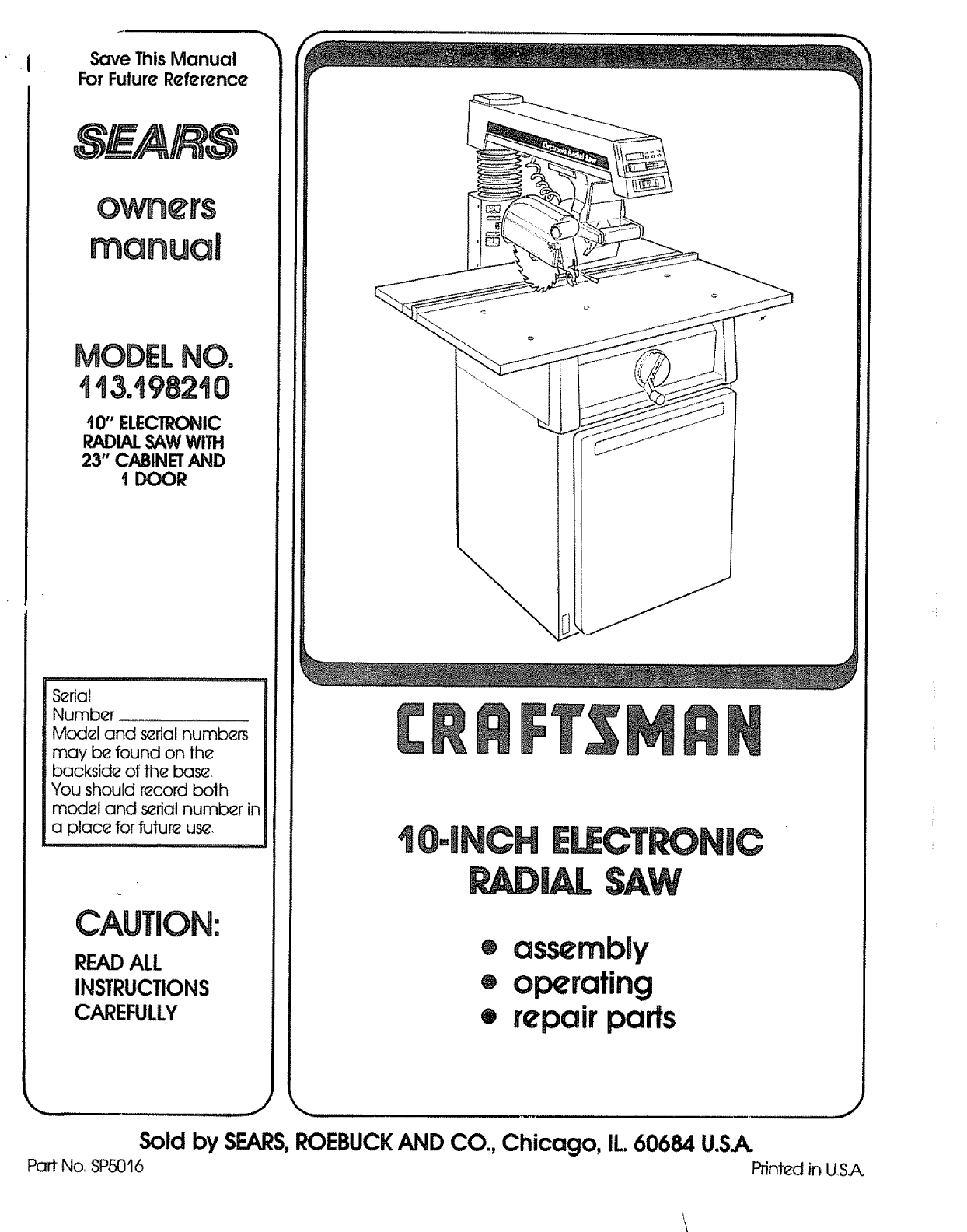
Save This Manual
For Future Reference
I0" ELECTRONIC
RADIALSAWWITH
23" CABINETAND
1 DOOR
S_rial
Number ...........
Model and s_rial numbers
may b_ found on the
backside of the base
You should record both
model and s_rial number in
a place for future us_,
CAUTION:
READALL
INSTRUCTIONS
CAREFULLY
I
® assembly
®operating
•repair parts
Sold by SEARS,ROEBUCKAND CO., Chicago, IL 60684 U.S.A.
Part No, SP5016 Printed in US.A.

FULL ONE YEAR WARRANTY ON CRAFTSMAN RADIAL SAW
If within one year from the date of purchase, this Craftsman Radial Saw fails due to a defect tn material or
workmanship,Sears will repair It, free of charge,,
WARRANTY SERVICE IS AVAILABLE BY SIMPLY CONTACTING THE NEAREST SEARS SERVICE
CENTER/DEPARTMENT THROUGHOUT THE UNITED STATES
This warranty appIies onty while this product 18used in the United Staten°
ThlBwarranty gives you specificlegal rights, and you may also have other rights which vary from state to 0late,
SEARS, ROEBUCK AND CO,,, DEPTo698/731A Sears Tower, Chicago, IL 60684
GENERAL SAFETY iNSTRUCTiONS FOR POWER TOOLS
1. KNOW YOUR POWER TOOL
Read and .understand the owner's manual and
labels affixed to the tool Learn its application
and limitations as weti as the specific potential
hazards peculiar to this loci
2o GROUND ALL TOOLS
This toot is equipped with an approved
3-conductor cord and a 3~prong grounding
type plug to fit the proper grounding type
receptacle The green conductor in the cord is
the grounding wire Never connect the green
wire to a live termina]
3. KEEP GUARDS IN PLACE,
in working order, and in proper adjustment and
alignment
4_ REMOVE ADJUSTING KEYS
AND WRENCHES
Form habit of checking to see that keys and
adjusting wrenches are removed from tool
before turning it on
5,, KEEP WORK AREA CLEAN
Cl_uttered areas and benches invite accidents
Floor must not be slippery due to wax or
sawdust
6, AVOID DANGEROUS ENVIRONMENT
Don't use power tools in damp or wet locations
or expose them to rain Keep work area wel!
lighted Provide adequate surrounding work
space
7o KEEP CHILDREN AWAY
AH visitors should be kept a safe distance from
work area
8. MAKE WORKSHOP CHILD-PROOF
with padlocks master switches, or by
removing starter keys
9. DON'T FORCE TOOL
It wilf do the job better and safer at the rate for
which it was designed
10. USE RIGHT TOOL
Don't force tool or attachment to do a job it was
not designed for
11_ WEAR PROPER APPAREL
Do not wear Goose clothing, gloves, neckties or
jewelry (rings, wrist watches) to get caught in
moving parts Nonslip footwear is
recommended Wear protective hair covering to
contain long hair Roll long sleeves above the
efbow
12_ USE SAFETY GOGGLES (Head Protection)
Wear Safety goggles (must comply with ANSI
Z871) at art times Everyday eyeglasses only
have impact resistant lenses, they are NOT
safety glasses. Also, use face or dust mask if
cutting operation is dusty, and ear protectors
(plugs or muffs) during extended periods of
operation
13o SECURE WORK
Use clamps or a vise to hold work when
practical It's safer than using your hand, frees
both hands to operate tool
14_ DON'T OVERREACH
Keep proper footing and balance at all times
15, MAINTAIN TOOLS WITH CARE
Keep tools sharp and clean for best and safest,
performances Follow instructions for
lubricating and changing accessories
16. DISCONNECT TOOLS
before servicing; when changing accessories
such as blades, bits., cutters, etc
17,, AVOID ACCIDENTAL STARTING
Make sure switch is in 'OFF" position before
plugging in
18, USE RECOMMENDED ACCESSORIES
Consult the owner's manual for recommended
accessories Follow the instructions that
accompany the accessories The use of
improper accessories may cause hazards
19. NEVER STAND ON TOOL
Serious injury could occur if the tool is tipped or
if the cutting tool is accidentally contacted
Do not store materials above or near the tool
such that it is necessary to stand on the tool to
reach them
20, CHECK DAMAGED PARTS
Before further use of the tool a guard or other
part that is damaged should be carefully
checked to ensure that it will operate properly
and perform its intended function Check fo_
alignment of moving parts, binding of moving
parts, breakage of parts, mounting, and any
other conditions that may effect its operation. A
guard or other part that is damaged should be
properly repaired or replaced
21o DIRECTION OF FEED
Feed work into a blade or cutter against the
direction of rotation of the blade or cutter only
22° NEVER LEAVE TOOL RUNNING
UNATTENDED
Turn power off Don't leave tool until it comes to
a complete stop
additionaU
BEFORE USING THE SAW:
instructions for radiaUsaws GO
t'¢= L--
OO*-,
m
WARNING: TO AVOID MISTAKES THAT COULD
RESULT IN SERIOUS, PERMANENT INJURY, DO
NOT CONNECT POWER CORD UNTIL THE FOL-
LOWING STEPS HAVE BEEN SATISFACTORILY
COMPLETED:
1. Assembly and alignment.. (See pages 15-24.)
2.. Examination and operating familiarity with ON-
OFF switch, elevation hand wheel, swivel lock,
bevel lock and rip lock, guard clamp screw,
spreader and anti-kickback device and miter
lock. (See pages 30, 31 & 32.)
3. Review and understanding of all safety instruc-
tions and operating procedures throughout the
manual
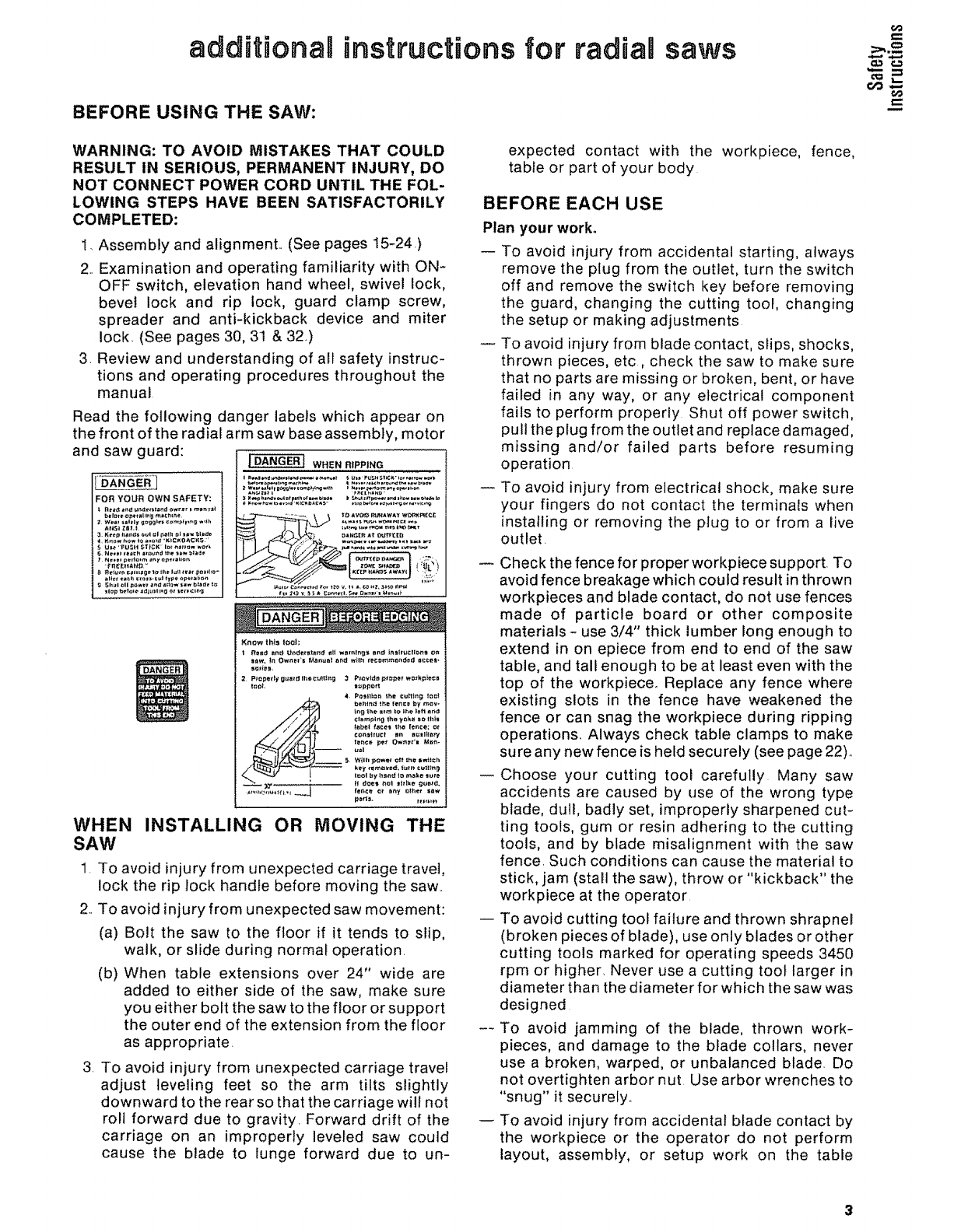
Read the following danger labels which appear on
the front of the radial arm saw base assembly, motor
and saw guard:
FOR YOUR OWN SAFETY:
WHEN RIPPING
WHEN INSTALLING OR MOVING THE
SAW
1. To avoid injury from unexpected carriage travel,
lock the rip lock handle before moving the saw..
2..To avoid injury from unexpected saw movement:
(a) Bolt the saw to the floor if it tends to slip,
walk, or slide during normal operation.
(b) When table extensions over 24" wide are
added to either side of the saw, make sure
you either bolt the saw to the floor or support
the outer end of the extension from the floor
as appropriate.
3. To avoid injury from unexpected carriage travel
adjust leveling feet so the arm tilts slightly
downward to the rear so that the carriage will not
roll forward due to gravity. Forward drift of the
carriage on an improperly leveled saw could
cause the blade to lunge forward due to un-
expected contact with the workpiece, fence,
table or part of your body
BEFORE EACH USE
Plan your work,
-- To avoid injury from accidental starting, always
remove the plug from the outlet, turn the switch
off and remove the switch key before removing
the guard, changing the cutting tool, changing
the setup or making adjustments
To avoid injury from blade contact, slips, shocks,
thrown pieces, etc, check the saw to make sure
that no parts are missing or broken, bent, or have
failed in any way, or any electrical component
fails to perform properly Shut off power switch,
pull the plug from the outlet and replace damaged,
missing and/or failed parts before resuming
operation
To avoid injury from electrical shock, make sure
your fingers do not contact the terminals when
installing or removing the plug to or from a live
outlet.
Check the fence for proper workpiece support. To
avoid fence breakage which could result in thrown
workpieces and blade contact, do not use fences
made of particle board or other composite
materials -use 3/4" thick lumber long enough to
extend in on epiece from end to end of the saw
table, and tall enough to be at least even with the
top of the workpiece. Replace any fence where
existing slots in the fence have weakened the
fence or can snag the workpiece during ripping
operations. Always check table clamps to make
sure any new fence is held securely (see page 22)_
Choose your cutting tool carefully Many saw
accidents are caused by use of the wrong type
blade, dull, badly set, improperly sharpened cut-
ting tools, gum or resin adhering to the cutting
tools, and by blade misalignment with the saw
fence. Such conditions can cause the material to
stick, jam (stall the saw), throw or "kickback" the
workpiece at the operator
-- To avoid cutting tool failure and thrown shrapnel
(broken pieces of blade), use only blades or other
cutting tools marked for operating speeds 3450
rpm or higher, Never use a cutting toot larger in
diameter than the diameter for which the saw was
designed
--To avoid jamming of the blade, thrown work-
pieces, and damage to the blade collars, never
use a broken, warped, or unbalanced blade. Do
not overtighten arbor nut Use arbor wrenches to
"snug" it securely°
To avoid injury from accidental blade contact by
the workpiece or the operator do not perform
layout, assembly, or setup work on the table
while the cuttingtool is rotating. Therotating
tool could cut and throw anythinghitting the
bladecaus{ngthe saw to unexpectedlycome
forward
Usetherightguard.Toavoidlosingcontrolofthe
workpiece,hittingthecuttingtool,orbeingstruck
bythrownpieces,neverdoanycuttingunlessthe
properguard(withallitspartsinplace)isinstalled
andadjustedproperly..
To avoidinjuryfromthrownpieces,slips,blade
contact,orjammingof theworkpiece,makesure
noplay existsbetweenthe columnand column
supportorin the carriage and that the arm, yoke,
bevel locks/clamps are tighL
To avoid injury from thrown objects, slips or
jamming of the blade due to pinching of the blade
by shifting boards:
(a) Do not leave a long board unsupported so the
spring of the board causes it to twist or rise
from the table
(b) Check to be sure that pieces will not fall off
the table once they have been cut.
(c) Provide support for the workpiece, based on
its size and the type of operation to be
performed
(d) Never use another person as a substitute fora
table extension, or as an additional support
for a workpiece to assist in feeding, support-
ing, or pulling the workpiece
(e) Never cut workpieces placed side to side or
stacked on top of each other The pieces can
slide on each other.
WEAR YOUR
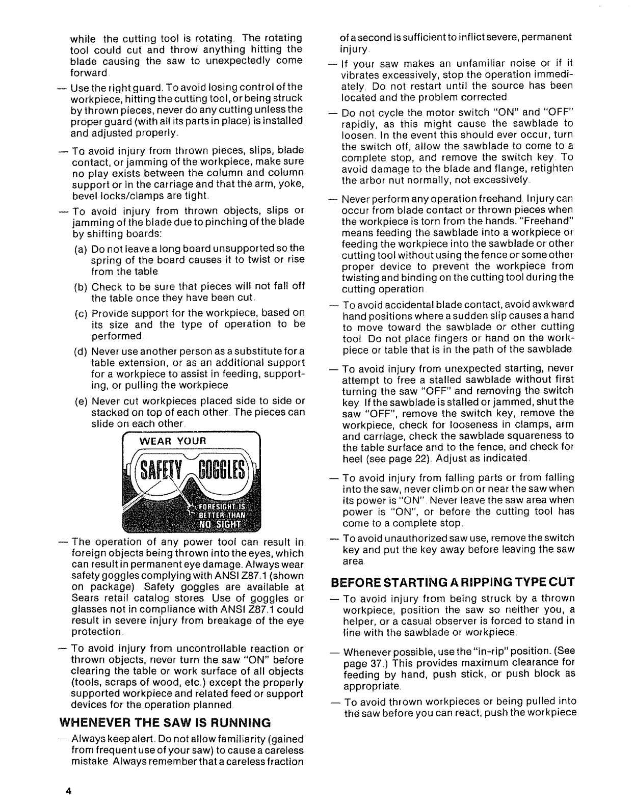
The operation of any power- tool can result in
foreign objects being thrown into the eyes, which
can result in permanent eye damage.. Always wear
safety goggles complying with ANSI Z87.1 (shown
on package) Safety goggles are available at
Sears retail catalog stores Use of goggles or
glasses not in compliance with ANSI Z87.1 could
result in severe injury from breakage of the eye
protection,
To avoid injury from uncontrollable reaction or
thrown objects, never turn the saw "ON" before
clearing the table or work surface of all objects
(tools, scraps of wood, etc..) except the properly
supported workpiece and related feed or support
devices for the operation planned
WHENEVER THE SAW IS RUNNING
-- Always keep alert. Do not allow familiarity (gained
from frequent use of your saw) to cause a careless
mistake. Always remember that a careless fraction
4
of asecond is sufficient to inflict severe, permanent
injury
if your saw makes an unfamiliar noise or' if it
vibrates excessively, stop the operation immedi-
ately, Do not restart until the source has been
located and the problem corrected
-- Do not cycle the motor switch "ON" and "OFF"
rapidly, as this might cause the sawblade to
loosen. In the event this should ever occur, turn
the switch off, allow the sawblade to come to a
complete stop, and remove the switch key To
avoid damage to the blade and flange, retighten
the arbor nut normally, not excessively..
-- Never perform any operation freehand injury can
occur from blade contact or' thrown pieces when
the workpiece is torn from the hands.. "Freehand"
means feeding the sawblade into a workpiece or
feeding the workpiece into the sawblade or other
cutting tool without using the fence orsome other
proper device to prevent the workpiece from
twisting and binding on the cutting tool during the
cutting operat[on
To avoid accidental blade contact, avoid awkward
hand positions where a sudden slip causes a hand
to move toward the sawblade or other cutting
tool Do not place fingers or hand on the work-
piece or table that is in the path of the sawblade
To avoid injury from unexpected starting, never
attempt to free a stalled sawblade without first
turning the saw "OFF" and removing the switch
key If the sawblade is statfed or' jammed, shut the
saw "OFF", remove the switch key, remove the
workpiece, check for' looseness in clamps, arm
and carriage, check the sawblade squareness to
the table surface and to the fence, and check for
heel (see page 22).. Adjust as indicated.
-- To avoid injury from falling parts or from falling
into the saw, never climb on or near the saw when
its power is "ON" Never leave the saw area when
power' is "ON", or before the cutting tool has
come to a complete stop.
To avoid unauthorized saw use, remove the switch
key and put the key away before leaving the saw
area
BEFORE STARTING A RIPPING TYPE CUT
To avoid injury from being struck by a thrown
workpiece, position the saw so neither you, a
helper', or a casual observer is forced to stand in
line with the sawbtade or workpiece.
-- Whenever possible, use the "in-rip" position_ (See
page 37_) This provides maximum clearance for
feeding by hand, push stick, or push block as
appropriate.
-- To avoid thrown workpieces or being pulled into
the saw before you can react, push the workpiece
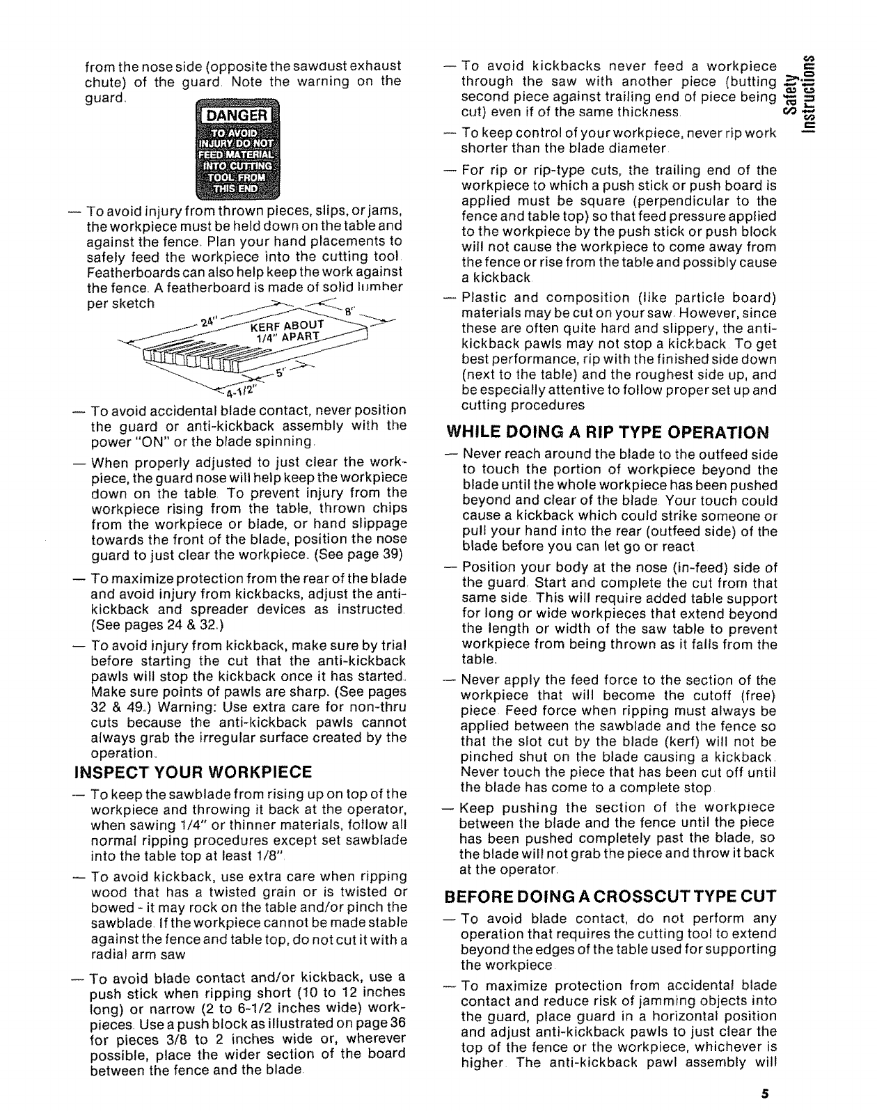
fromthenoseside(oppositethesawdustexhaust
chute)of the guard. Note the warningon the
guard..
Toavoidinjuryfromthrownpieces,slips,orjams,
theworkpiecemustbehelddownonthetableand
againstthefence..Planyourhandplacementsto
safelyfeedthe workpieceinto the cutting tool.
Featherboardscanalsohelpkeeptheworkagainst
thefence.A featherboardismadeof solidlumher
persketch !._-_--A__ _,.
Toavoidaccidentalbladecontact,neverposition
the guard or anti-kickbackassemblywith the
power"ON"orthebladespinning.
-- Whenproperlyadjustedto just clearthe work-
piece,theguardnosewillhelpkeeptheworkpiece
down on the table.To preventinjury from the
workpiecerising from the table,thrown chips
from the workpieceor blade,or handslippage
towardsthefront of theblade,positionthenose
guardto justcleartheworkpiece..(Seepage39)
-- Tomaximizeprotectionfromtherearoftheblade
andavoidinjuryfromkickbacks,adjusttheanti-
kickback and spreaderdevicesas instructed.
(Seepages24&32.)
-- Toavoidinjuryfromkickback,makesurebytrial
before starting the cut that the anti-kickback
pawlswill stopthe kickbackonceit hasstarted..
Makesurepointsof pawlsaresharp,(Seepages
32& 49°)Warning:Useextracarefor nomthru
cuts becausethe anti-kickbackpawls cannot
alwaysgrabtheirregularsurfacecreatedbythe
operation.
INSPECT YOUR WORKPIECE
-- Tokeepthesawbladefromrisingupontopofthe
workpieceandthrowingit backat theoperator,
whensawing1/4" or thinnermaterials,followall
normalrippingproceduresexceptsetsawblade
intothetabletopat least1/8",
To avoidkickback,useextracarewhenripping
wood that hasa twistedgrain or is twistedor
bowed- it mayrockon thetableand/orpinchthe
sawblade,Iftheworkpiececannotbemadestable
againstthefenceandtabletop,donotcutit witha
radialarmsaw
To avoidbladecontactand/or kickback,usea
pushstick whenrippingshort (10to 12 inches
long) or narrow(2 to 6-1/2incheswide)work-
pieces.Useapushblockasillustratedon page36
for pieces3/8 to 2 incheswide or, wherever
possible,placethe widersection of the board
betweenthefenceandtheblade.
To avoid kickbacks never feed a workpiece
through the saw with another piece (butting _'_-_
second piece against trailing end of piece being '_ =
cut) even if of the same thickness, c,_ 6O
To keep control of your workpiece, never rip work
shorter than the blade diameter
For rip or rip-type cuts, the trailing end of the
workpiece to which a push stick or push board is
applied must be square (perpendicular to the
fence and table top) so that feed pressure applied
to the workpiece by the push stick or push block
will not cause the workpiece to come away from
the fence or rise from the table and possibly cause
a kickback
Plastic and composition (like particle board)
materials may be cut on your saw. However, since
these are often quite hard and slippery, the anti-
kickback pawls may not stop a kickback To get
best performance, rip with the finished side down
(next to the table) and the roughest side up, and
be especially attentive to follow proper set up and
cutting procedures
WHILE DOING A RIP TYPE OPERATION
-- Never reach around the blade to the outfeed side
to touch the portion of workpiece beyond the
blade until the whole workpiece has been pushed
beyond and ctear of the blade Your touch could
cause a kickback which could strike someone or
pull your hand into the rear (outfeed side) of the
blade before you can let go or react
-- Position your body at the nose (in-feed) side of
the guard, Start and complete the cut from that
same side This will require added table support
for long or wide workpieces that extend beyond
the length or width of the saw table to prevent
workpiece from being thrown as it falls from the
table,,
Never apply the feed force to the section of the
workpiece that will become the cutoff (free)
piece. Feed force when ripping must always be
applied between the sawblade and the fence so
that the slot cut by the blade (kerf) will not be
pinched shut on the blade causing a kickback.
Never touch the piece that has been cut off until
the blade has come to a complete stop
--Keep pushing the section of the workpiece
between the blade and the fence until the piece
has been pushed completely past the blade, so
the blade wilt not grab the piece and throw it back
at the operator.
BEFORE DOING A CROSSCUT TYPE CUT
--To avoid blade contact, do not perform any
operation that requires the cutting tool to extend
beyond the edges of the table used for supporting
the workpiece
To maximize protection from accidental blade
contact and reduce risk of jamming objects into
the guard, place guard in a horizontal position
and adjust anti-kickback pawls to just clear the
top of the fence or the workpiece, whichever is
higher The anti-kickback pawl assembly will
5
provide additional guarding from contact with the
front of the blade.
To prevent the cutting tool from grabbing the
table or workpiece and being propelled toward
you, never lower a revolving cutting tool into the
table or a workpiece without first locking the rip
lock handle and clamping the workpiece in place.
Release the handle only after having firmly
grasped the carriage handle.
To avoid blade contact or injury from a thrown cut
off piece, never use a length stop on the cut off
end or edge of the workpiece. Never hang onto or'
touch the cut off piece of the workpiece while the
power is "ON" and/or the sawblade is rotating To
prevent pinching that could cause the piece to be
thrown, the cut off piece must never be confined,
pushed, or grabbed while the blade is spinning.
INSPECT YOUR WORKPIECE
To avoid injury from thrown objects, slips or
jamming of the blade, make sure the workpiece
will fit the supports (fence, table, fixtures or jigs)
so it will not twist, rock or otherwise bind on the
cutting tool. Make sure there is no sawdust or
other foreign material between the workpiece and
its support.
WHILE DOING A CROSSCUT TYPE CUT
Always start with the carriage in the full rear
position behind the fence before turning the saw
On,
Never push the carriage and blade backwards
into the work to do a crosscutting type operation..
The cutting tool can throw the work over the
fence, striking someone or causing you to fall into
the blade.
Always return the carriage to the full rearward
position behind the fence at the completion of
each crosscut type operation Never remove your'
hand from the yoke handle unless the carriage is
in this position. Otherwise, the cutting tool may
climb up on the workpiece and be propelled
toward you.
BEFORE USING ACCESSORIES
To avoid injury from unanticipated hazards, use
only recommended accessories as listed on page
50°
The use of grinding wheels, abrasive or cut off
wheels, or wire wheels, can be dangerous and are
not recommended_ Such devices can break ex-
plosively and throw shrapnel, causing severe
injury
The sawblade, dado, or other cutting tool must be
removed from the saw arbor before using the
accessory shaft, Never operate the saw with
cutting tools (including sanding accessories or
buffing) installed on both ends of the saw arbor to
avoid being pulled into moving parts by hair,
threads, clothing, etc, Make sure the unused
arbor is always covered by aguard, the arm, or the
screw cap
Using a drill chuck, To avoid injury from sudden
bending or breaking of a drill bit, do not install or
use twist drills tonger than 7" in iength or extend-
ing more than 6" beyond the chuck jaws. Do not
instatl or use any reduced shank drill except the
opade type (1" diameter' or smaller).. Use for
drilling wood or plastic only - bit speed cannot be
properly adjusted for other materiafs. Do not use
twist drills larger than 1/2" in diameter
glossary of terms for woodworking
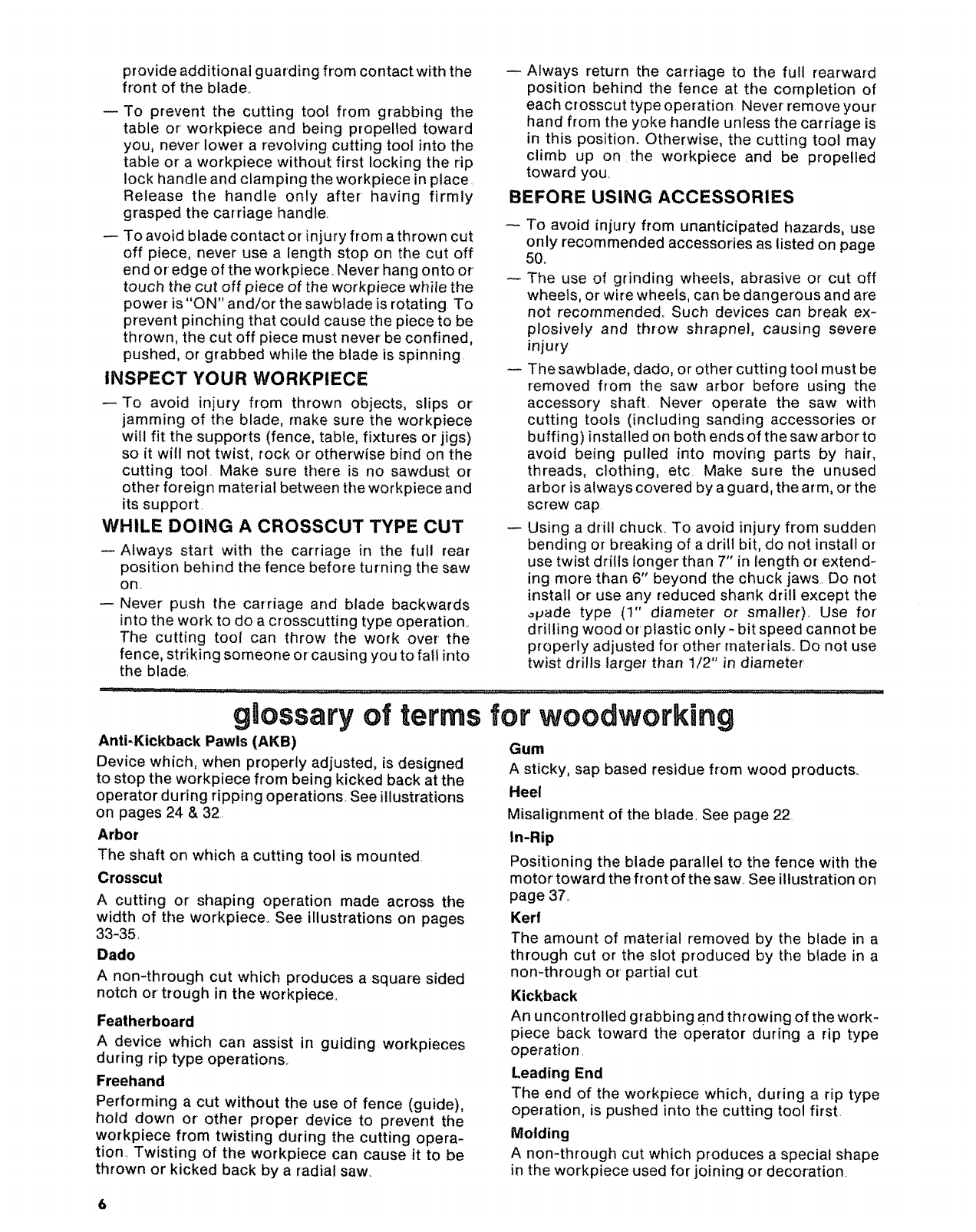
Anti-Kickback Pawls (AKB)
Device which, when properly adjusted, is designed
to stop the workpiece from being kicked back at the
operator during ripping operations. See illustrations
on pages 24 & 32.
Arbor
The shaft on which acutting tool is mounted,
Crosscut
A cutting or shaping operation made across the
width of the workpiece_ See illustrations on pages
33-35
Dado
A non-through cut which produces a square sided
notch or' trough in the workpieceo
Featherboard
A device which can assist in guiding workpieces
during rip type operations.
Freehand
Performing a cut without the use of fence (guide),
hold down or other proper device to prevent the
workpiece from twisting during the cutting opera-
tion. Twisting of the workpiece can cause it to be
thrown or kicked back by a radial saw
Gum
A sticky, sap based residue from wood products..
Heel
Misalignment of the blade. See page 22
In-Rip
Positioning the blade parallel to the fence with the
motor toward the front of the saw_See illustration on
page 37_
Kerf
The amount of material removed by the blade in a
through cut or the slot produced by the blade in a
non-through or' partial cut
Kickback
An uncontrolled grabbing arid throwing of the work-
piece back toward the operator during a rip type
operation
Leading End
The end of the workpiece which, during a rip type
operation, is pushed into the cutting tool first
Molding
A non-through cut which produces a special shape
in the workpiece used for joining or decoration
Outrip
Positioningthebladeparallelto thefencewiththe
motortowardthe rearof the sawproducingmaxi-
mumrippingcapacity_Seeillustrationon page37,
Push Stick
A device used to feed the workpiece through the saw
during narrow ripping type operations so the oper-
ator's hands are kept well away from the blade, See
page 36,
Push Block
A device used for ripping type operations too narrow
to allow use of a push stick_ See page 36.
Rabbet
A notch in the edge of a workpiece.
Resin
A sticky, sap base substance that has hardened,
Ripping
Acutting operation along the length of the work-
piece,
Revolutions Per Minute (RPM)
The number of turns completed by a spinning object
in one minute,
Sawblade Path
The area of the workpiece or table top directly in line
with either the travel of the blade or the part of the
workpiece which will be, or has been, cut by the
blade,
Set
The distance that the tip of the sawblade tooth is so
m
bent (or set) outward from the face of the blade, .3 "_,
Throw-Back .-
Throwing of small pieces in a manner similar to a _ =
kickback, _.u (=
Thru-Sawing
Any cutting operation where the blade extends
completely through the thickness of the workpiece,
Trailing End
The workpiece end last cut by the blade in a ripping
operation
Workpiece
The item on which the cutting operation is being
performed The surfaces of a workpiece are com-
monly referred to as faces, ends, and edges,
electrical connections
POWER SUPPLY
1. Motor Specifications
The A-C motor used in this saw is acapacitor-start,
non-reversible type having the following specifica-
tions:
Rated HoP....................................... 1.5
Maximum Developed H,P ........................ 25
Voltage ........................................ 120
Amperes ...................................... 11
Hertz (cycles) .................................. 60
Phase ........................................ Single
RPM ....................................... 3450
Rotation of Blade Arbor ................ Clockwise
WARNING: TO AVOID ELECTRICAL HAZARDS,
FIRE HAZARDS, OR DAMAGE TO THE TOOL, USE
PROPER CIRCUIT PROTECTION. YOUR SAW IS
WIRED ATTHE FACTORY FOR 120V OPERATION.
CONNECT TO A 120V, 15-AMP, BRANCH CIRCUIT
AND USE A 15-AMP, TIME DELAY FUSE OR
CIRCUIT BREAKER.
IF NOT PROPERLY GROUNDED THIS POWER
TOOL CAN CAUSE ELECTRICAL SHOCK -
PARTICULARLY WHEN USED IN DAMP LOCA-
TIONS IN PROXIMITY TO PLUMBING. IF AN
ELECTRICAL SHOCK OCCURS THERE IS ALSO
THE POTENTIAL OF A SECONDARY HAZARD
SUCH AS YOUR HANDS CONTACTING THE
SAWBLADE. NOT ALL OUTLETS ARE PROPERLY
GROUNDED. TO AVOID SHOCK OR FIRE, IF
POWER CORD tS WORN OR CUT, OR DAMAGED
tN ANY WAY, HAVE IT REPLACED IMMEDIATELY.
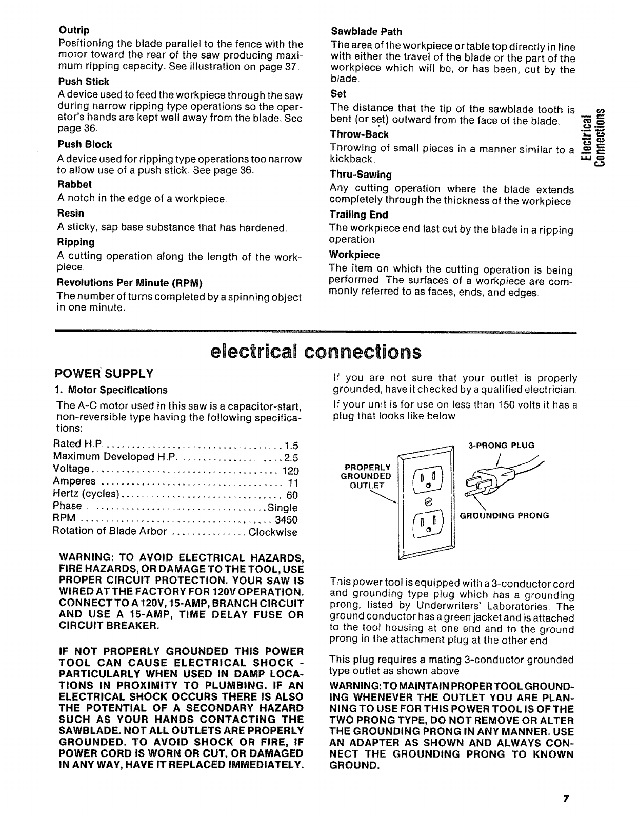
If you are not sure that your outlet is properly
grounded, have it checked by a qualified electrician
If your unit is for use on less than 150 volts it has a
plug that looks like below
PROPERLY
GROUNDED
OUTLET
3-PRONG PLUG
GROUNDING PRONG
This power tool is equipped with a 3-conductor cord
and grounding type plug which has a grounding
prong, listed by Underwriters' Laboratories The
ground conductor has a green jacket and is attached
to the tool housing at one end and to the ground
prong in the attachment plug at the other end
This plug requires a mating 3-conductor grounded
type outlet as shown above
WARNING: TO MAINTAIN PROPER TOOL GROUND-
ING WHENEVER THE OUTLET YOU ARE PLAN-
NING TO USE FOR THIS POWER TOOL IS OFTHE
TWO PRONG TYPE, DO NOT REMOVE OR ALTER
THE GROUNDING PRONG IN ANY MANNER. USE
AN ADAPTER AS SHOWN AND ALWAYS CON-
NECT THE GROUNDING PRONG TO KNOWN
GROUND.
It isrecommendedthatyouhaveaqualifiedelectri-
cian replacethe two prongoutlet witha properly
groundedthreeprongoutlet,
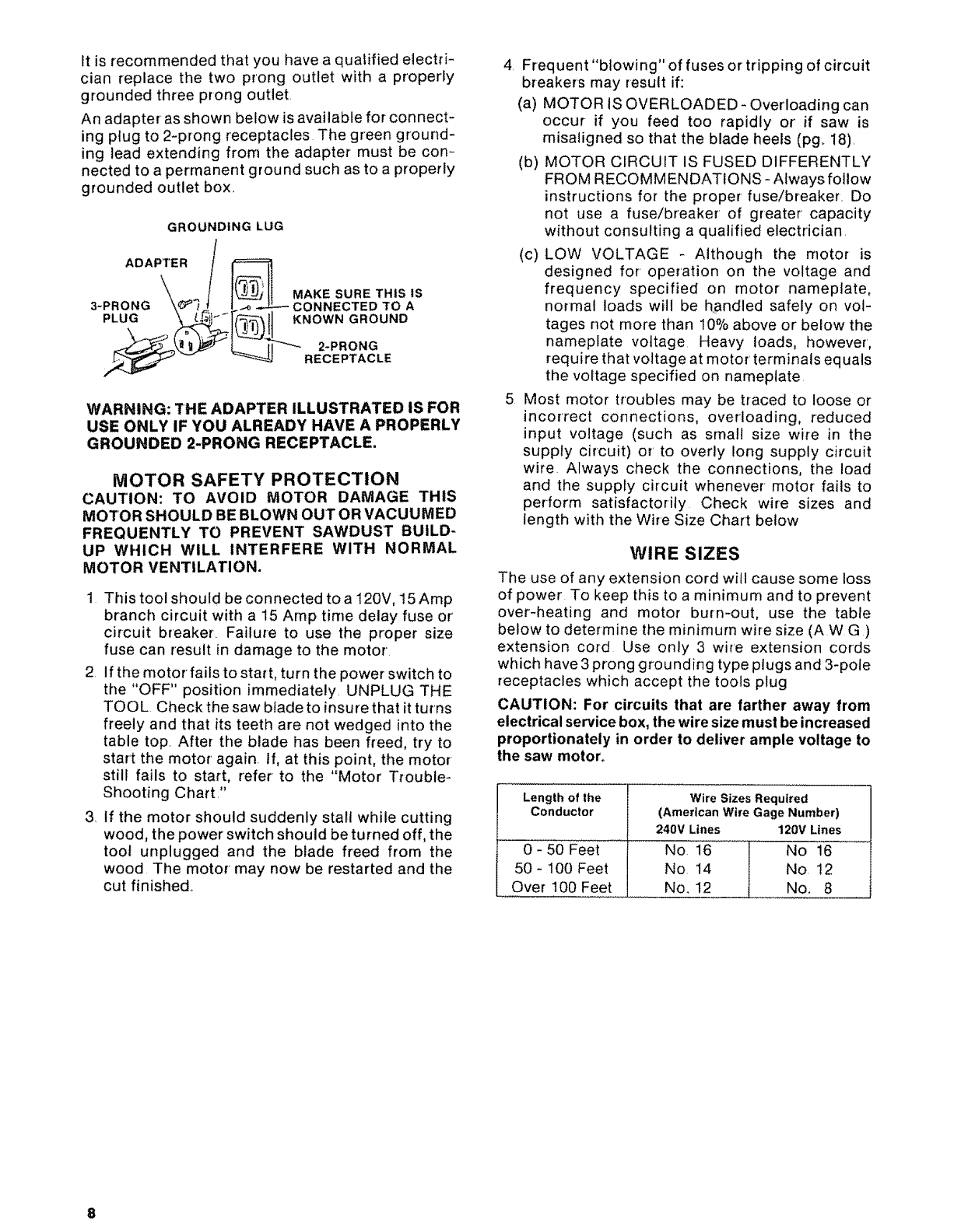
Anadapterasshownbelowisavailablefor connect-
ingplugto 2-prongreceptaclesThegreenground-
ing leadextendingfrom the adaptermustbecon-
nectedto apermanentgroundsuchasto aproperly
groundedoutletbox.
GROUNDING LUG
ADAPTER /I_..___.
_MAKE SURE THIS IS
3-PRONG "_! i CONNECTEDTOA
PLUG _- r[_ {t,_ .... NOWN GROUND
RECEPTACLE
WARNING: THE ADAPTER ILLUSTRATED IS FOR
USE ONLY IF YOU ALREADY HAVE A PROPERLY
GROUNDED 2-PRONG RECEPTACLE.
MOTOR SAFETY PROTECTION
CAUTION: TO AVOID MOTOR DAMAGE THIS
MOTOR SHOULD BE BLOWN OUT OR VACUUMED
FREQUENTLY TO PREVENT SAWDUST BUILD-
UP WHICH WILL INTERFERE WITH NORMAL
MOTOR VENTILATION.
1 This tool should be connected to a t20V, 15 Amp
branch circuit with a 15 Amp time delay fuse or'
circuit breaker. Failure to use the proper size
fuse can result in damage to the motor.
2. If the motor fails to start, turn the power switch to
the "OFF" position immediately. UNPLUG THE
TOOL. Check the saw blade to insure that it turns
freely and that its teeth are not wedged into the
table top. After the blade has been freed, try to
start the motor' again. If, at this point, the motor'
still fails to start, refer to the "Motor Trouble-
Shooting Chart?'
3. If the motor should suddenly stall while cutting
wood, the power switch should be turned off, the
toot unplugged and the blade freed from the
wood The motor' may now be restarted and the
cut finished.
4. Frequent "blowing" of fuses or tripping of circuit
breakers may result if:
(a) MOTOR IS OVERLOADED - Overloading can
occur-if you feed too rapidly or' if saw is
misaligned so that the blade heels (pg_ 18).
(b) MOTOR CIRCUIT IS FUSED DIFFERENTLY
FROM RECOMMENDATIONS- Always follow
instructions for the proper fuse/breaker. Do
not use a fuse/breaker of greater capacity
without consuFting a qualified electrician.
(c) LOW VOLTAGE - Although the motor is
designed for operation on the voltage and
frequency specified on motor nameplate,
normal loads will be handled safely on vol-
tages not more than 10% above or below the
nameplate voltage Heavy loads, however,
require that voltage at motor terminals equals
the voltage specified on nameplate
5 Most motor troubles may be traced to loose or
incorrect connections, overloading, reduced
input voltage (such as small size wire in the
supply circuit) or to overly long supply circuit
wire Always check the connections, the load
and the supply circuit whenever motor fails to
perform satisfactorily Check wire sizes and
length with the Wire Size Chart below
WIRE SIZES
The use of any extension cord will cause some loss
of power To keep this to a minimum and to prevent
over-heating and motor burn-out, use the table
below to determine the minimum wire size (AWG)
extension cord Use only 3 wire extension cords
which have 3 prong grounding type plugs and 3-pole
receptacles which accept the tools plug
CAUTION: For circuits that are farther away from
electrical service box, the wire size must be increased
proportionately in order to deliver ample voltage to
the saw motor°
Length of the
Conductor
0 - 50 Feet
50 - 100 Feet
Over 100 Feet
Wire Sizes Required
(American Wire Gage Number)
240V Lines 120V Lines
No 16 No 16
No 14 No 12
No. 12 No. 8
contents
Page
Guarantee .................................... 2
General Safety Instructions for Power Tools .... 2
Additional Safety Instructions for Radial Saws oo 3
Glossary of Terms for Woodworking ........... 6
Electrical Connections .......................... 7
Assembly and Alignment ........................ 9
Unpacking and Preassembly ................ 10
Alignment Procedure ....................... 18
Page
Location and Function of Controls ............ 29
Basic Saw Operations ........................... 33
Adjustments to Compensate for Wear ......... 39
Trouble Shooting .............................. 43
Maintenance and Lubrication .................. 49
Recommended Accessories ................... 50
Repair Parts ................................. 52
,,i,,,, ' ' ................ _,,_,,i,, i,,,i, =r,,i.......... i...... i " " _ "" ........... i,,, ,,, ,,,,,i,
o=1 (,rt
=
o,}-_
,=_
assembRy and aRignment
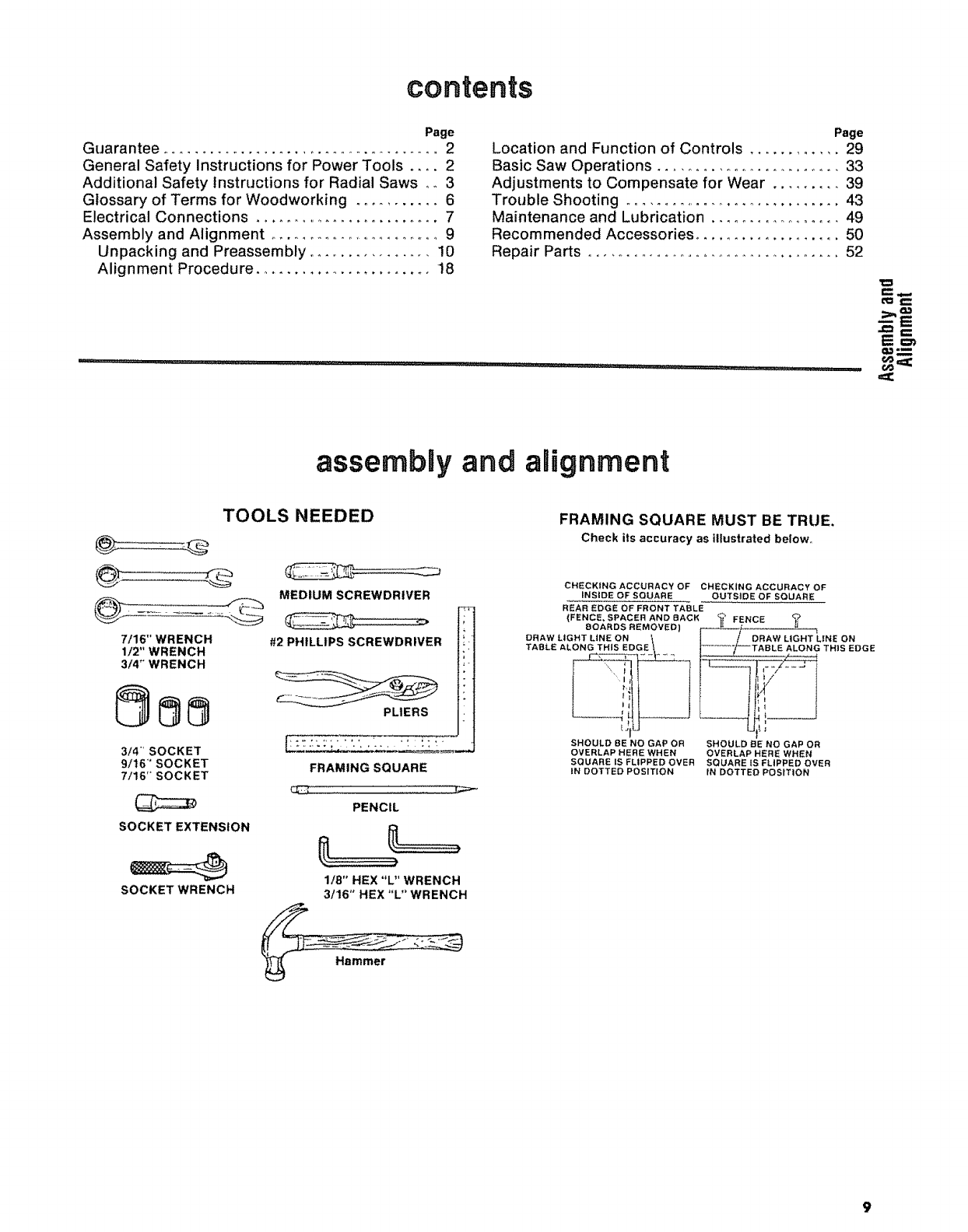
TOOLS NEEDED
7/16" WRENCH
1/2" WRENCH
3/4" WRENCH
MEDIUM SCREWDRIVER
#2 PHILLIPS SCREWDRIVER
PLIERS
3/4" SOCKET
9/16" SOCKET
7/16" SOCKET
SOCKET EXTENSION
SOCKET WRENCH
FRAMING SQUARE
PENCIL
1/8" HEX "L" WRENCH
3/16" HEX "L" WRENCH
FRAMING SQUARE MUST BE TRUE,
Check its accuracy as illustrated below
CHECKING ACCURACY OF CHECKING ACCURACY OF
INSIDE OF SQUARE OUTSIDE OF SQUARE
REAR EDGE OF FRONT TABLE
(FENCE, SPACER AND BACK _FENCE
EIOARDS REMOVED) f-"--=_/ ....
DRAW LIGHT LiNE ON _ _ /DRAW LIGHT L|NE ON
TABLE ALONG THIS EDGE Ij_'i--TABLE ALONG THtS EDGE
t_lU LJIL J
SHOULD 8E NO GAP OR SHOULD BE NO GAP OR
OVERLAP HERE WHEN OVERLAP HERE WHEN
SQUARE IS FLIPPED OVER SQUARE iS FLIPPED OVER
tN DOTTED POSITION IN DOTTED POSITION
9
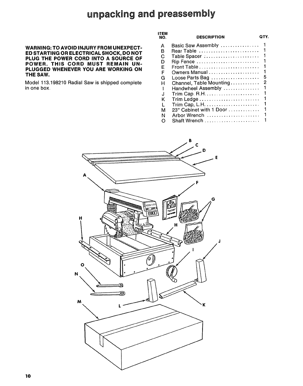
unpacking and pteassembly
WARNING: TO AVOID INJURY FROM UNEXPECT-
ED STARTING OR ELECTRICAL SHOCK, DO NOT
PLUG THE POWER CORD INTO A SOURCE OF
POWER. THIS CORD MUST REMAIN UN-
PLUGGED WHENEVER YOU ARE WORKING ON
THE SAW.
Model 113.198210 Radial Saw is shipped complete
in one box
ITEM
NOo DESCRIPTION QTY,.
A Basic Saw Assembly ................ 1
B Rear Table ......................... 1
C Table Spacer :...................... 1
D Rip Fence ........................... I
E Front Table ......................... 1
F Owners Manual ...................... 1
G Loose Parts Bag ..................... 5
H Channel, Table Mounting ............ 2
1 Handwheef Assembly ............... 1
J Trim Cap, R.H ......................... 1
K Trim Ledge ............................. 1
LTrim Cap, L.H ....................... 1
M 23" Cabinet with 1 Door .............. 1
N Arbor Wrench ....................... 1
O Shaft Wrench ........................ 1
A
CD
F
H
M\
G
H
,/
I0
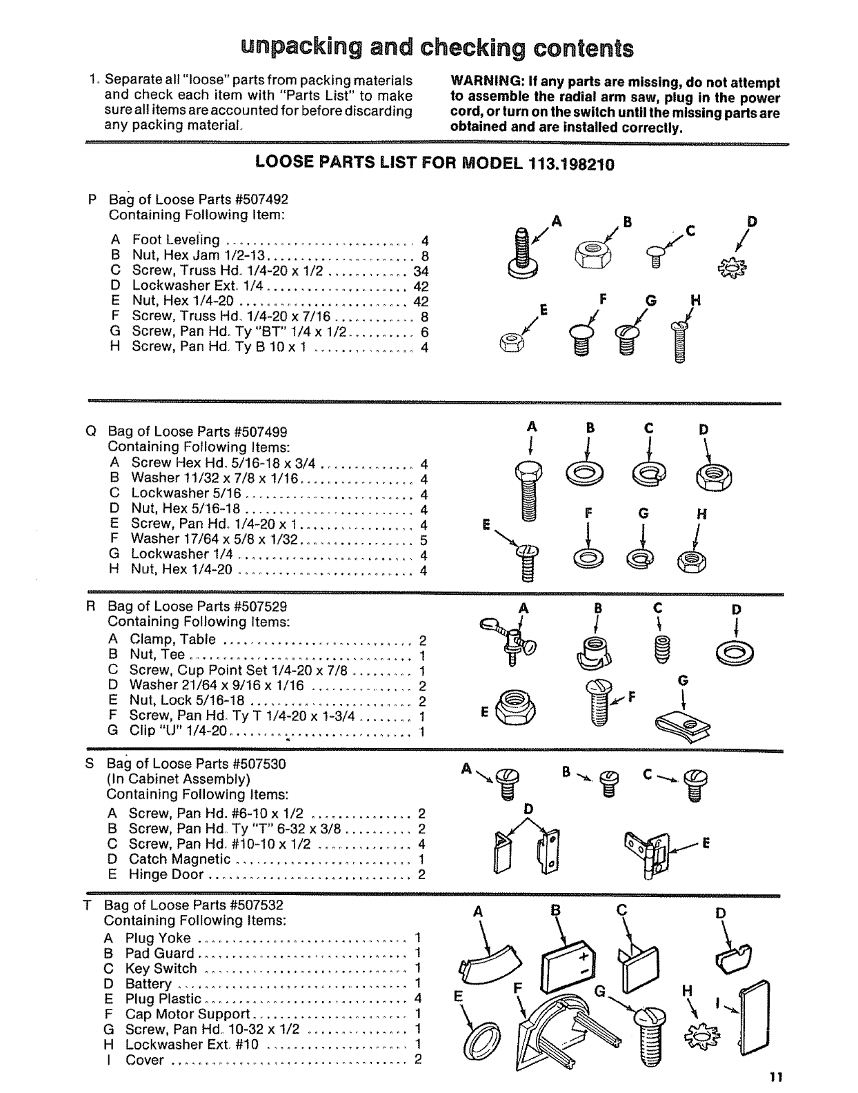
unpacking and checking contents
1, Separate all "loose" parts from packing materials WARNING: If any parts are missing, do not attempt
and check each item with "Parts List" to make to assemble the radial arm saw, plug in the power
sure all items are accounted for before discarding cord, or turn on the switch until the missing parts are
any packing material obtained and are installed correclly.
LOOSE PARTS LIST FOR MODEL 113.198210
PBag of Loose Parts #507492
Containing Following Item:
A Foot LevelLing ............................. 4
B Nut, Hex Jam 1/2-13 ...................... 8
C Screw, Truss Hd. 1/4-20 x 1/2 ............ 34
D Lockwasher Exto 1/4 ..................... 42
E Nut, Hex 1/4-20 .......................... 42
F Screw, Truss Hdo 1/4-20 x 7/16 ............ 8
G Screw, Pan Hdo Ty "BT" 1/4 x 1/2 .......... 6
H Screw, Pan Hd. Ty B 10 x 1 ............... 4
A B
F G H
D
/
@
QBag of Loose Parts #507499
Containing Following Items:
A Screw Hex Hd, 5/16-18 x 3/4 .............. 4
B Washer!1i32x7/8x !/16 ................. 4
A B C
CLockwasher 5/16 .......................... 4
D Nut, Hex 5/16-18 ........................... 4
E Screw, Pan Hd. 1/4-20 x 1.................. 4
F Washer 17/64 x 5/8 x 1/32 .................. 5
G Lockwasher 1/4 ........................... 4
H Nut, Hex 1/4-20 ............................ 4
F G
E
R Bag of Loose Parts #507529 A B C
Containing Following Items: _ _ _
A Clamp, Table .............................. 2
B Nut, Tee .................................. 1
C Screw, Cup Point Set 1/4-20 x 7/8 .......... 1
D Washer 21/64 x 9/16 x 1/16 ................ 2
E Nut, Lock 5/16-I8 ........................ 2 ,/_,, _,,_. F
F Screw, Pan Hd_ Ty T 1/4-20 x 1-3/4 ........ 1 E
G Clip"U" 1/4-20 ........................... 1
SBali of Loose Parts #507530
(In Cabinet Assembly)
Containing Following Items:
A Screw, Pan Hd. #6-10 x 1/2 ............... 2
B Screw, Pan Hd. Ty "T" 6-32 x 3/8 .......... 2
C Screw, Pan Hd. #10-10 x 1/2 .............. 4
D Catch Magnetic .......................... 1
E Hinge Door ............................... 2
D
G
D
i,,i,,,i,,,i1,1111111,1,1 i,ii, ,
T Bag of Loose Parts #507532
Containing Following Items:
A
B
C
D
E
F
G
H
I
Plug Yoke ................................ 1
Pad Guard ................................ 1
Key Switch .............................. 1
Battery .................................... !
Plug Plastic .............................. 4
Cap Motor Support ....................... 1
Screw, Pan Hal. 10-32 x 1/2 ............... 1
Lockwasher Ext. #I0 ....................... 1
Cover ................................... 2
A B
E
H
D
,,ll .........
i,i. i i
CD
\l
@
11
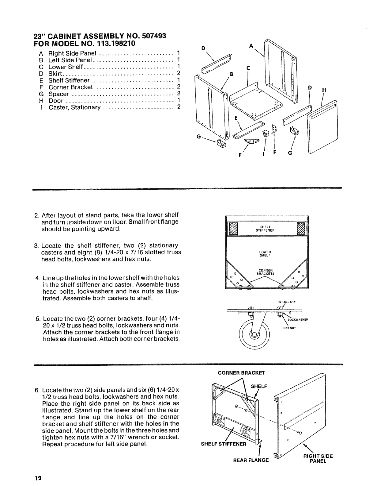
23" CABINET ASSEMBLY NO. 507493
FOR MODEL NO. 113.198210
A Right Side Panel ............................ 1
BLeft Side Panel ........................... 1
C Lower' Shelf ............................... 1
D Skirt ....................................... 2
E Shelf Stiffener ............................ 1
F Corner Bracket ............................ 2
G Spacer ................................... 2
HDoor'......................................1
t Caster, Stationary ......................... 2
DA
H
F i F
%
G
................ i i ii i:llllllllll i i lllllll i,iii, lUlHI
2. After layout of stand parts, take the lower shelf
and turn upside down on floor. Small front flange
should be pointing upward.
3o Locate the shelf stiffener, two (2) stationary
casters and eight (8) 1/4-20 x 7/!6 slotted truss
head bolts, Iockwashers and hex nuts.
4 Line up the holes in the lower shelf with the holes
in the shelf stiffener and caster Assemble truss
head bolts, Iockwashers and hex nuts as illus-
trated. Assemble both casters to shell
5 Locate the two (2) corner brackets, four (4) 1/4-
20 x 1/2 truss head bolts, Iockwashers and nuts
Attach the corner brackets to the front flange in
holes as illustrated. Attach both corner brackets
SHELF
STIFFENER
LOWER
SHELF
I_e,".;10x ?;1_i'
/lr'.i r,r_ /
6 Locatethe two (2) side panelsand six (6) 1/4-20 x
1/2 truss head bolts, Iockwashers and hex nuts
Place the right side panel on its back side as
illustrated_ Stand up the lower shelf on the rear
flange and line up the holes on the corner
bracket and shelf stiffener with the holes in the
side panel. Mount the bolts in the three holes and
tighten hex nuts with a 7/16" wrench or socket
Repeat procedure for left side panel
CORNER BRACKET
SHELF
SHELF STIFFENER
REAR FLANGE RIGHT SIDE
PANEL
12
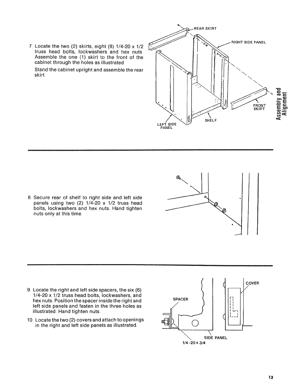
SKIRT
7. Locate the two (2) skirts, eight (8) 1/4-20 x 1/2
truss head bolts, Iockwashers and hex nuts.
Assemble the one (1) skirt to the front of the
cabinet through the holes as illustrated.
Stand the cabinet upright and assemble the rear
skirt
LEFT SIDE
PANEL
SHELF
SIDE PANEL
\"\
FRONT
SKIRT
8. Secure rear of shelf to right side and left side
panels using two (2) 1/4-20 x 1/2 truss head
bolts, Iockwashers and hex nuts.. Hand tighten
nuts only at this time.
i_ll ,,i,1,1,1,11, _111 i ,i ...... illl
9. Locate the right and left side spacers, the six (6)
1/4-20 x 1/2 truss head bolts, Iockwashers, and
hex nuts.. Position the spacer inside the right and
left side panels and fasten in the three holes as
illustrated. Hand tighten nuts.
I0 Locate the two (2) covers and attach to openings
in the right and left side panels as illustrated..
SPACER
//
©
SIDE PANEL
t/4- 20 x 3/4
FI
L
!l I
iL._J
COVER
/
13
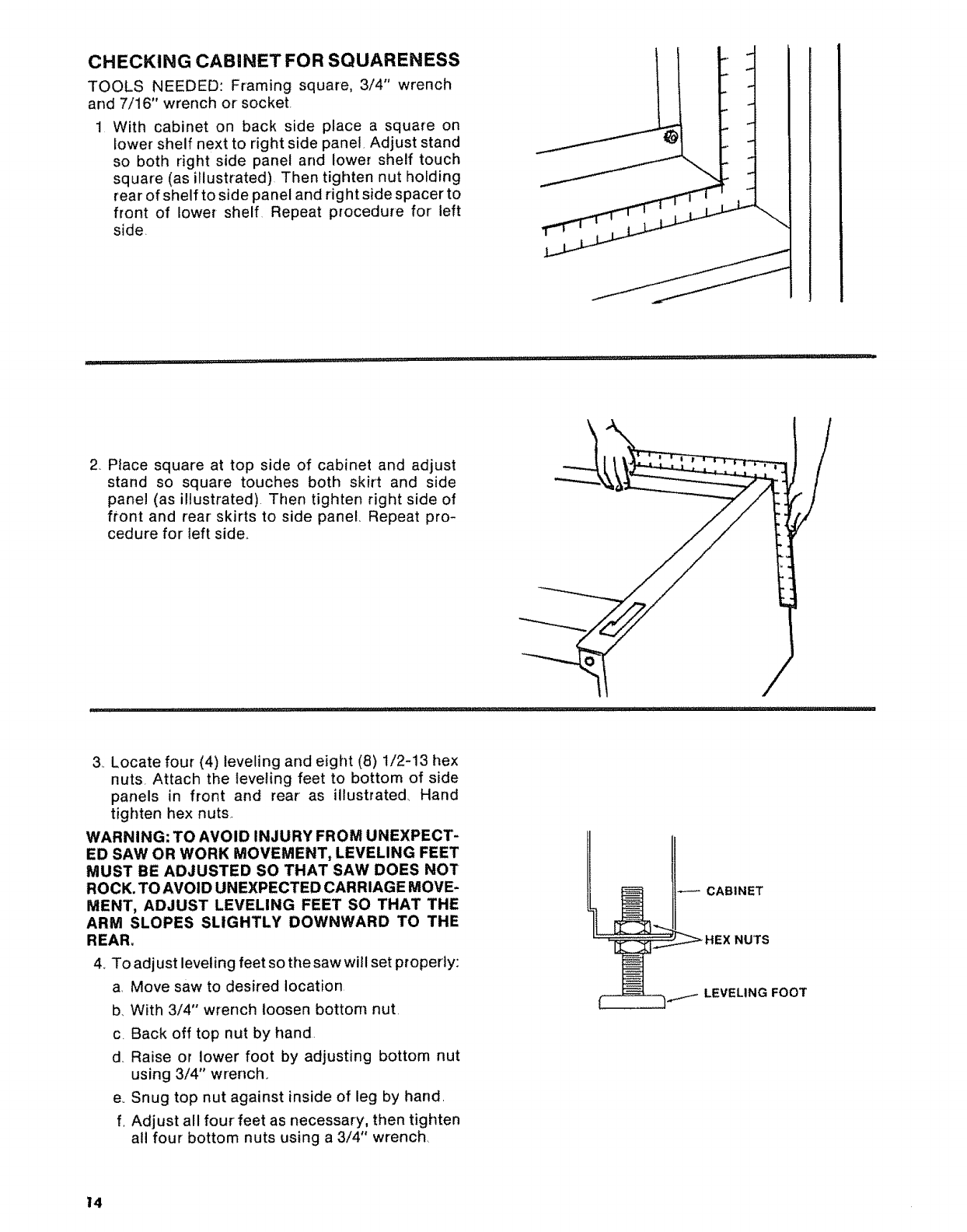
CHECKING CABINET FOR SQUARENESS
TOOLS NEEDED: Framing square, 3/4" wrench
and 7/16" wrench or socket.
1 With cabinet on back side place a square on
lower shelf next to right side panel, Adjust stand
so both right side panel and lower shelf touch
square (as illustrated) Then tighten nut holding
rear of shelf to side panel and right side spacer to
front of lower shelf Repeat procedure for left
side,
i , , i,ii,,, rlH"' ,ill i,ilrl :
2 PIace square at top side of cabinet and adjust
stand so square touches both skirt and side
panel (as illustrated) Then tighten right side of
front and rear skirts to side panel, Repeat pro-
cedure for left side°
3, Locate four (4) leveling and eight (8) !/2-13 hex
nuts Attach the leveling feet to bottom of side
panels in front and rear as illustrated, Hand
tighten hex nuts.
WARNING: TO AVOID INJURY FROM UNEXPECT-
ED SAW OR WORK MOVEMENT, LEVELING FEET
MUST BE ADJUSTED SO THAT SAW DOES NOT
ROCK. TO AVOID UNEXPECTED CARRIAGE MOVE-
MENT, ADJUST LEVELING FEET SO THAT THE
ARM SLOPES SLIGHTLY DOWNWARD TO THE
REAR.
4. To adjust leveling feet so the saw will set properly:
aMove saw to desired location
b, With 3/4" wrench loosen bottom nut,
c. Back off top nut by hand
d Raise or lower foot by adjusting bottom nut
using 3/4" wrench,
e, Snug top nut against inside of leg by hand,
f, Adjust all four feet as necessary, then tighten
all four bottom nuts using a 3/4" wrench
t4
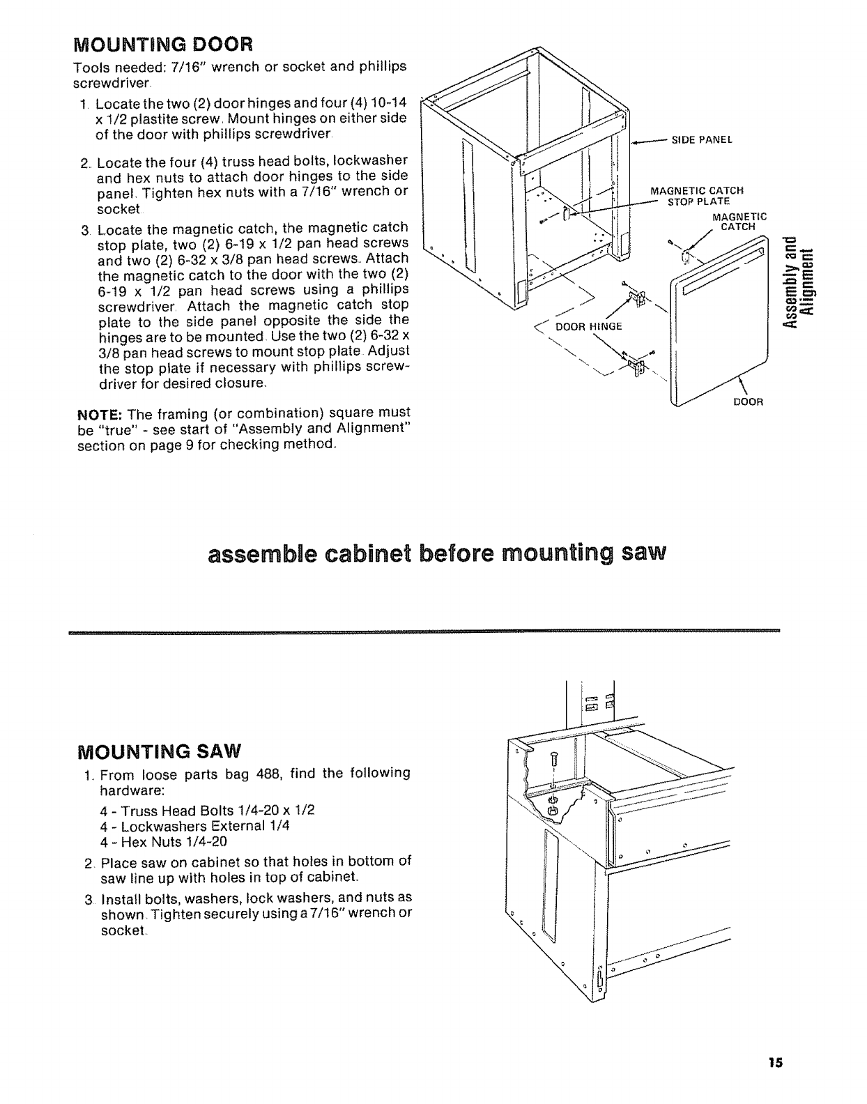
iVIOUNTBNG DOOR
Tools needed: 7/16" wrench or socket and phillips
screwd river,
1, Locate the two (2) door hinges and four (4) 10-14
x 1/2 plastite screw, Mount hinges on either side
of the door with phillips screwdriver,
2, Locate the four (4) truss head bolts, lockwasher
and hex nuts to attach door hinges to the side
panel, Tighten hex nuts with a 7/16" wrench or
socket
3 Locate the magnetic catch, the magnetic catch
stop plate, two (2) 6-19 x 1/2 pan head screws
and two (2) 6-32 x 3/8 pan head screws, Attach
the magnetic catch to the door with the two (2)
6-19 x 1/2 pan head screws using a phillips
screwdriver, Attach the magnetic catch stop
plate to the side panel opposite the side the
hinges are to be mounted. Use the two (2) 6-32 x
3/8 pan head screws to mount stop plate Adjust
the stop plate if necessary with phillips screw-
driver for desired closure,
NOTE: The framing (or combination) square must
be "true" - see start of "Assembly and Alignment"
section on page 9 for checking method.,
\
MAGNETIC CATCH
STOP PLATE
MAGNETIC
CATCH
assembae cabinet before mounting saw
NIOUNTING SAW
1., From loose parts bag 488, find the following
hardware:
4 - Truss Head Bolts 1/4-20 x1/2
4- Lockwashers External 1/4
4- Hex Nuts 1/4-20
2. Place saw on cabinet so that holes in bottom of
saw line up with holes in top of cabinet,,
3 Install bolts, washers, lock washers, and nuts as
shown. Tighten securety using a 7/! 6" wrench or
socket,
15
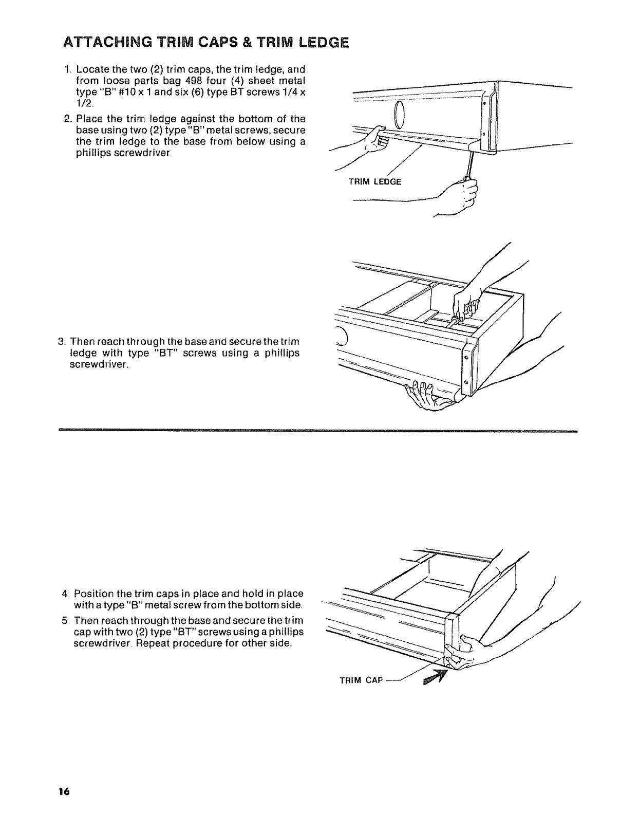
ATTACHING TRiM CAPS & TRiM LEDGE
1. Locate the two (2) trim caps, the trim ledge, and
from loose parts bag 498 four (4) sheet metal
type "B" #10 x i and six (6) type BT screws 1/4 x
1/2o
2_ Place the trim ledge against the bottom of the
base using two (2) type"B" metal screws, secure
the trim ledge to the base from below using a
phillips screwdriver.
TRIM LEDGE
3, Then reach through the base and secure the trim
ledge with type "BT" screws using a phillips
screwdriver_
4, Position the trim caps in place and hold in place
with a type "B" metal screw from the bottom side.
5. Then reach through the base and secure the trim
cap with two (2) type "BT" screws using a phillips
screwdriver. Repeat procedure for other side,
16
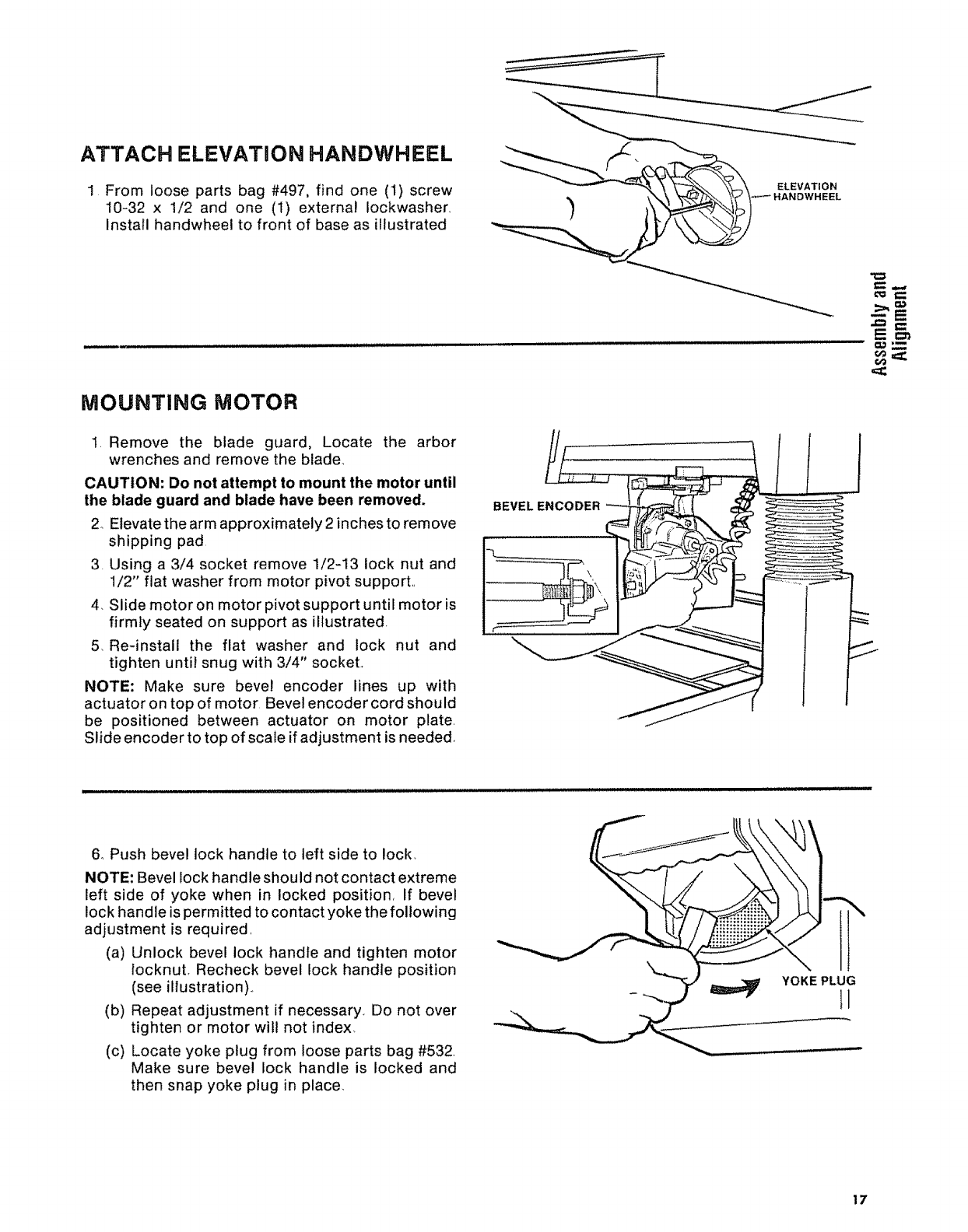
ATTACH ELEVATION HANDWHEEL
1 From loose parts bag #497, find one (1) screw
10-32 x 1/2 and one (I) external Iockwasher
Install handwheel to front of base as illustrated
ELEVATION
,IANDWHEEL
MOUNTING MOTOR
1, Remove the blade guard, Locate the arbor
wrenches and remove the blade_
CAUTION: Do not attempt to mount the motor until
the blade guard and blade have been removed.
2 Elevate the arm approximately 2 inches to remove
shipping pad
3. Using a 3/4 socket remove 1/2-13 lock nut and
1/2" flat washer from motor pivot support.,
4, Slide motor on motor pivot support until motor is
firmly seated on support as illustrated,
5, Re-install the flat washer and lock nut and
tighten until snug with 3/4" sockeL
NOTE: Make sure bevel encoder lines up with
actuator on top of motor Bevel encoder cord should
be positioned between actuator on motor plate,
Slide encoder to top of scale if adjustment is needed,
_,,,,
BEVEL ENCODER
--E
6, Push bevel lock handle to left side to lock,
NOTE: Bevel lock handle shou Id not contact extreme
left side of yoke when in locked position, If bevel
lock handle is permitted to contact yoke the following
adjustment is required,
(a) Unlock bevel lock handle and tighten motor
locknut, Recheck bevel lock handle position
(see illustration).,
(b) Repeat adjustment if necessary. Do not over
tighten or motor will not index,
(c) Locate yoke plug from loose parts bag #532,
Make sure bevel lock handle is locked and
then snap yoke plug in place
YOKE PLUG
II
17
ALIIGNMENT PROCEDURE
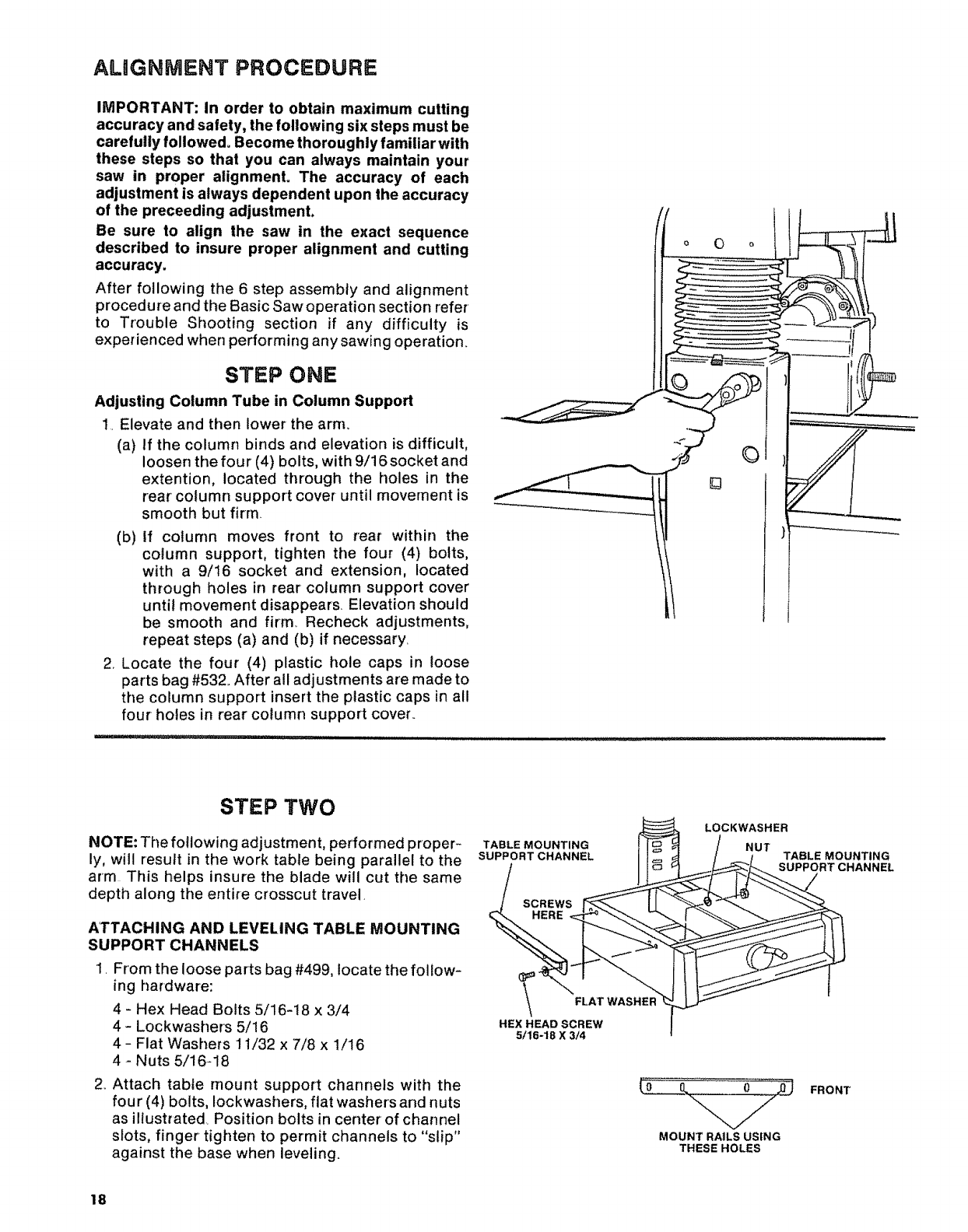
IMPORTANT: In order to obtain maximum cutting
accuracy and safety, the following six steps must be
carefully followed° Become thoroughly familiar with
these steps so that you can always maintain your
saw in proper alignment° The accuracy of each
adjustment is always dependent upon the accuracy
of the preceeding adjustment.
Be sure to align the saw in the exact sequence
described to insure proper alignment and cutting
accuracy.
After following the 6 step assembly and alignment
procedure and the Basic Saw operation section refer
to Trouble Shooting section if any difficulty is
experienced when performing any sawing operation.
STEP ONE
Adjusting Column Tube in Column Support
1• Elevate and then lower the arm.
(a) If the column binds and elevation is difficult,
loosen the four (4) bolts, with 9/16 socket and
extention, located through the holes in the
rear column support cover until movement is
smooth but firm.
(b) If column moves front to rear within the
column support, tighten the four (4) bolts,
with a 9/16 socket and extension, located
through holes in rear column support cover
until movement disappears. Elevation should
be smooth and firm, Recheck adjustments,
repeat steps (a) and (b) if necessary.
2.. Locate the four (4) plastic hole caps in loose
parts bag #532_ After all adjustments are made to
the column support insert the plastic caps in all
four holes in rear column support cover.
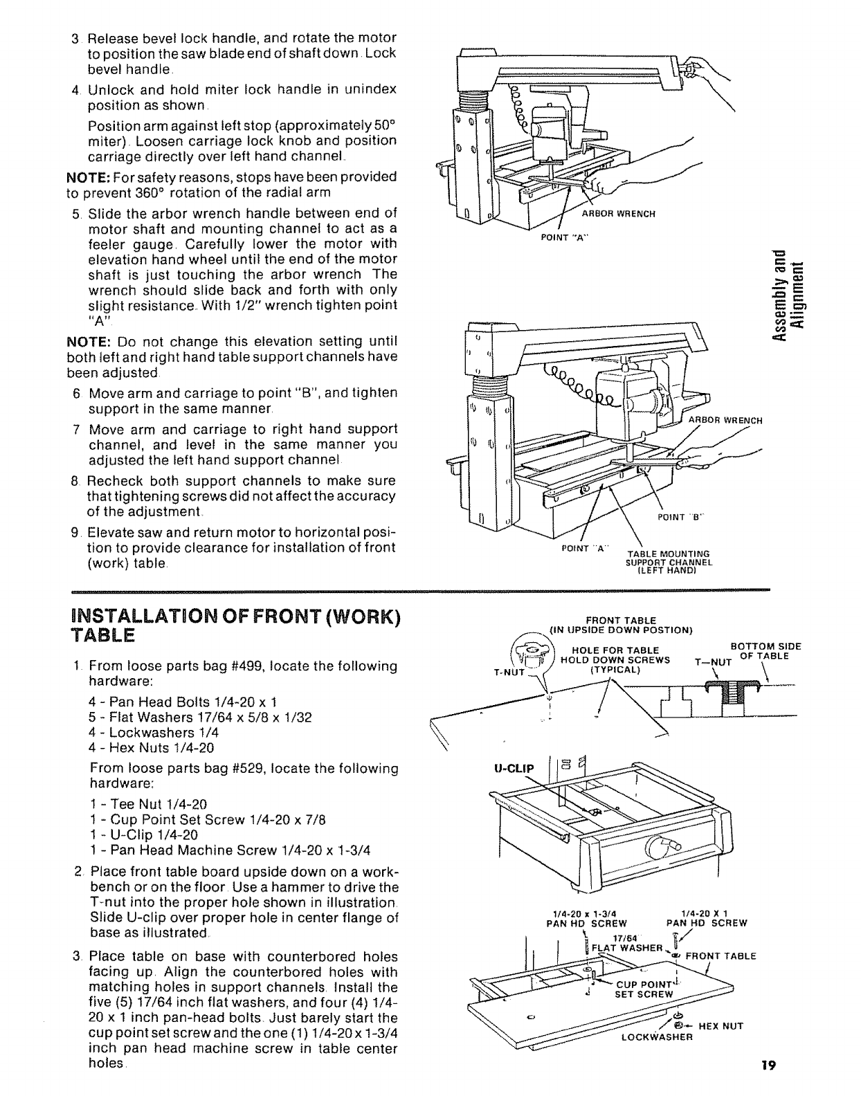
STEP TWO
NOTE: The following adjustment, performed proper-
ly, will result in the work table being parallel to the
arm This helps insure the blade will cut the same
depth along the entire crosscut travel.
ATTACHING AND LEVELING TABLE MOUNTING
SUPPORT CHANNELS
i. From the loose parts bag #499, locate the follow-
ing hardware:
4-Hex Head Bolts 5/16-18 x 3/4
4 - Lockwashers 5/16
4- Flat Washers 11/32 x 7/8 x 1/16
4-Nuts 5/16-18
2. Attach table mount support channels with the
four (4) bolts, Iockwashers, flat washers and nuts
as illustrated Position bolts in center of channel
s_ots, finger tighten to permit channels to "slip"
against the base when leveling.
TABLE MOUNTING
SUPPORT CHANNEL
SCREWS
HERE
FLAT
HEX HEAD SCREW
5/16-18 X 3/4
LOCKWASHER
NUT TABLE MOUNTING
SUPPORT CHANNEL
MOUNT RAILS USING
THESE HOLES
FRONT
18
3 Releasebevellockhandle,androtatethemotor
topositionthesawbladeendofshaftdown.Lock
bevelhandle,
4 Unlockand hold miter lock handlein unindex
positionasshown,
Positionarmagainstleftstop(approximately50°
miter),Loosencarriagelockknobandposition
carriagedirectlyoverleft handchannel
NOTE:Forsafetyreasons,stopshavebeenprovided
to prevent360° rotationof theradialarm
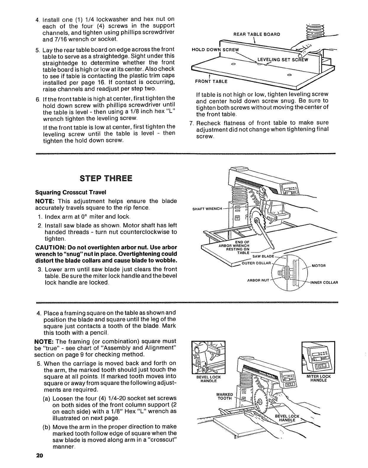
5. Slidethearborwrenchhandlebetweenendof
motor shaft and mounting channel to act as a
feeler gauge, Carefully lower the motor with
elevation hand wheel until the end of the motor
shaft is just touching the arbor wrench The
wrench should slide back and forth with only
slight resistance,, With 1/2" wrench tighten point
I_A _
NOTE: Do not change this elevation setting until
both teft and right hand table support channels have
been adjusted
6 Move arm and carriage to point "B", and tighten
support in the same manner,
7 Move arm and carriage to right hand support
channel, and level in the same manner you
adjusted the teft hand support channel
8 Recheck both support channels to make sure
that tightening screws did not affect the accuracy
of the adjustment,
9, Elevate saw and return motor to horizontal posi-
tion to provide clearance for installation of front
(work) table.
F
ARBOR WRENCH
POINT "*A"
ARBOR WRENCH
POINT -A" TABLE MOUNTING
SUPPORT CHANNEL
(LEFT HAND)
Em'_
€,o ,==;
INSTALLATION OF FRONT (WORK)
TABLE FRONT TABLE
1 From loose parts bag #499, locate the following
hardware:
4 - Pan Head Bolts 1/4-20 x 1
5 - Flat Washers 17/64 x 5/8 x !/32
4 - Lockwashers 1/4
4 - Hex Nuts If4-20
From loose parts bag #529, locate the following
hardware:
t - Tee Nut 1/4-20
1 - Cup Point Set Screw 1/4-20 x 7/8
1 - U-Clip 1/4-20
1 - Pan Head Machine Screw 1/4-20 x I-3/4
2 Place front table board upside down on a work-
bench or on the floor. Use a hammer to drive the
T-nut into the proper hole shown in illustration
Slide U-clip over proper hole in center flange of
base as illustrated,
3. Place table on base with counterbored holes
facing up, Align the counterbored holes with
matching holes in support channels, lnstall the
five (5) 17/64 inch flat washers, and four (4) 1/4-
20 x 1 inch pan-head bolts, Just barely start the
cup point set screw and the one (1) 1/4-20 x !-3/4
inch pan head machine screw in table center
holes,
IJ-CLIP
1/4-20 x %3/4
PAN HD SCREW
1/4-20 X 1
PAN HD SCREW
19
4. Install one (1) 1/4 Iockwasherandhex nut on
each of the four' (4) screws in the support
channels,andtightenusingphillipsscrewdriver
and7/16wrenchor'socket.
5. Laythereartableboardonedgeacrossthefront
tableto serveasastraightedge_Sightunderthis
straightedgeto determinewhetherthe front
tableboardishighorlowatitscenter.Alsocheck
to seeif tableiscontactingtheplastictrimcaps
installedper page16.If contactis occurring,
raisechannelsandreadjustpersteptwo.,
6. Ifthefronttableishighatcenter,firsttightenthe
holddownscrewwith phillipsscrewdriveruntil
thetableis level- thenusinga 1/8inchhex"L"
wrenchtightenthelevelingscrew.
If thefronttableislowatcenter,firsttightenthe
levelingscrew unti! the table is level- then
tightentheholddownscrew°
tf tableisnothighor low,tightenlevelingscrew
and centerholddownscrewsnug.Be sureto
tightenbothscrewswithoutmovingthecenter'of
thefronttable..
7..Recheckflatnessof front table to makesure
adjustmentdidnotchangewhentighteningfinal
screw..
STEP THREE
Squaring Crosscut Travel
NOTE: This adjustment helps ensure the blade
accurately travels square to the rip fence,
1, Index arm at 0°miter and lock,,
2 Install saw blade as shown.. Motor shaft has left
handed threads - turn nut counterclockwise to
tighten_
CAUTION: Do not overtighten arbor nut. Use arbor
wrench to "snug" nut in place. Overtightening could
distort the blade collars and cause blade to wobble.
3. Lower arm until saw blade just clears the front
table. Be sure the miter lock handle and the bevel
lock handle are locked.
SH
4.. Place a framing square on the table as shown and
position the blade and square until the leg of the
square just contacts a tooth of the blade. Mark
this tooth with a pencil,
NOTE: The framing (or combination) square must
be "true" - see chart of "Assembly and Alignment"
section on page 9 for checking method.
5, When the carriage is moved back and forth on
the arm, the marked tooth should just touch the
square at all points.. If marked tooth moves into
square or away from square the following adjust-
ments are required,
(a) Loosen the four (4) 1/4-20 socket set screws
on both sides of the front column support (2
on each side) with a 1/8" Hex "L" wrench as
illustrated on next page
(b) Move the arm in the proper direction to make
marked tooth follow edge of square when the
saw blade is moved along arm in a "crosscut"
manner'.
BEVEL LOCK
HANDLE
MARKED
TOOTH
MITER LOCK
HANDLE
2O
(c) Carefully retighten tJpper two (2) 1/4_20 socket
set screws alternating from left side to right
side so as not to force arm out of adjustment°
(d) Recheck blade travel° Adjust arm position as
needed by readjusting upper screws only,
(e) Once arm position is good, tighten lower 1/4-
20 socket set screws. Do not overtighten.
Check elevating handwheel for ease of rota-
tion., If rotating handwhee! is difficult, re-
adjust socket set screw tighteness as needed.
NOTE: The life of your saw table will be lengthened
considerably if you will cover the front table with a
fitted piece of 1/4 inch plywood° This should be
tacked in place for easy replacemenL Use of such a
cover will allow you to do all cutting into the cover,
rather than your table top,. This will help prevent
dulling of the saw blade and striking table mounting
hardware., Place tacks out of the path of the saw
blade°
FOUR SOCKET
HEAD SCREWS
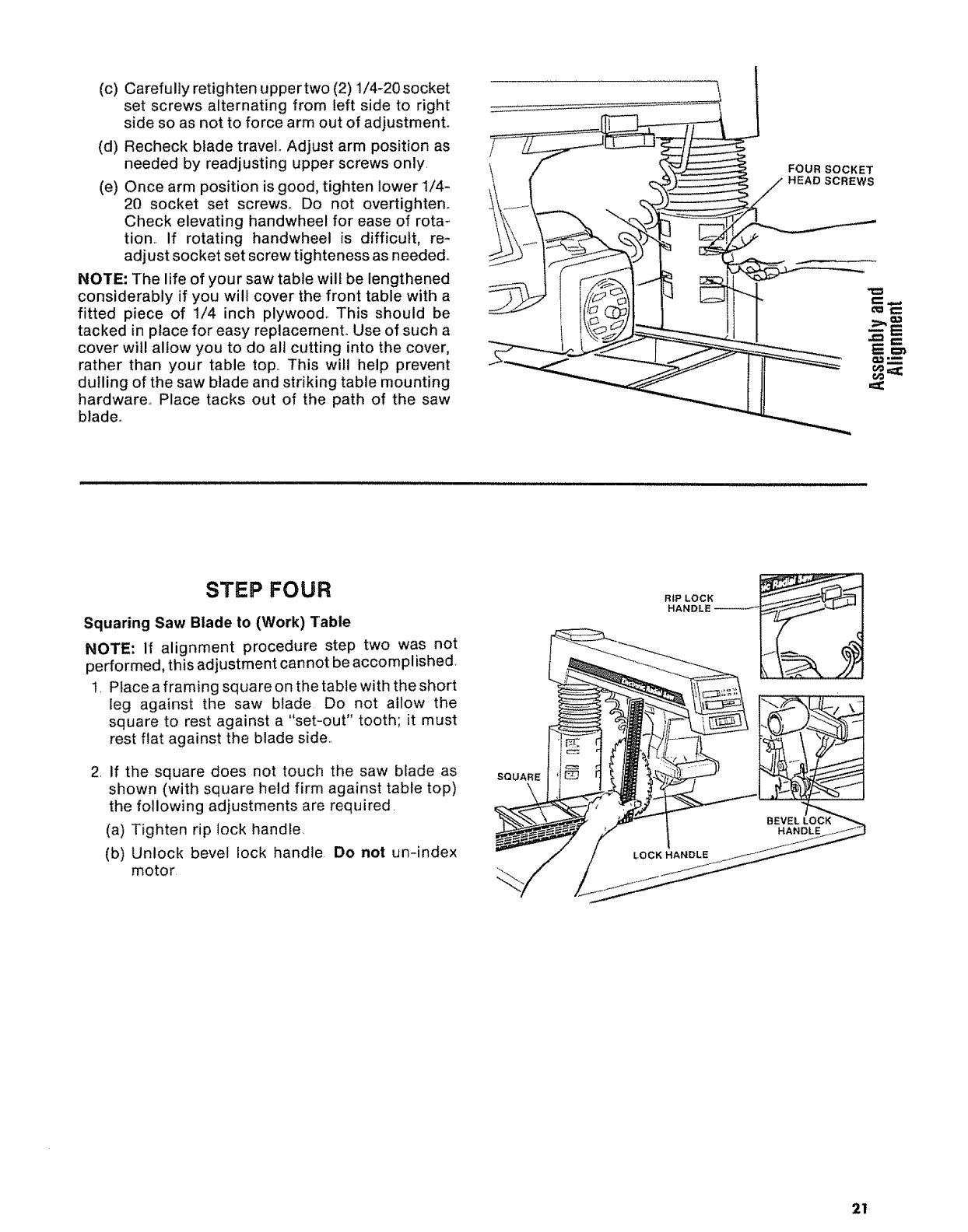
STEP FOUR
Squaring Saw Blade to (Work) Table
NOTE: if alignment procedure step two was not
performed, this adjustment cannot be accomplished,
1, Place a framing square on the table with the short
leg against the saw blade Do not allow the
square to rest against a "set-out" tooth; it must
rest flat against the blade side,,
2. If the square does not touch the saw blade as
shown (with square held firm against table top)
the following adjustments are required.
(a) Tighten rip lock handle.
(b) Unlock bevel lock handle Do not un-index
motor
SQUARE
\
2!
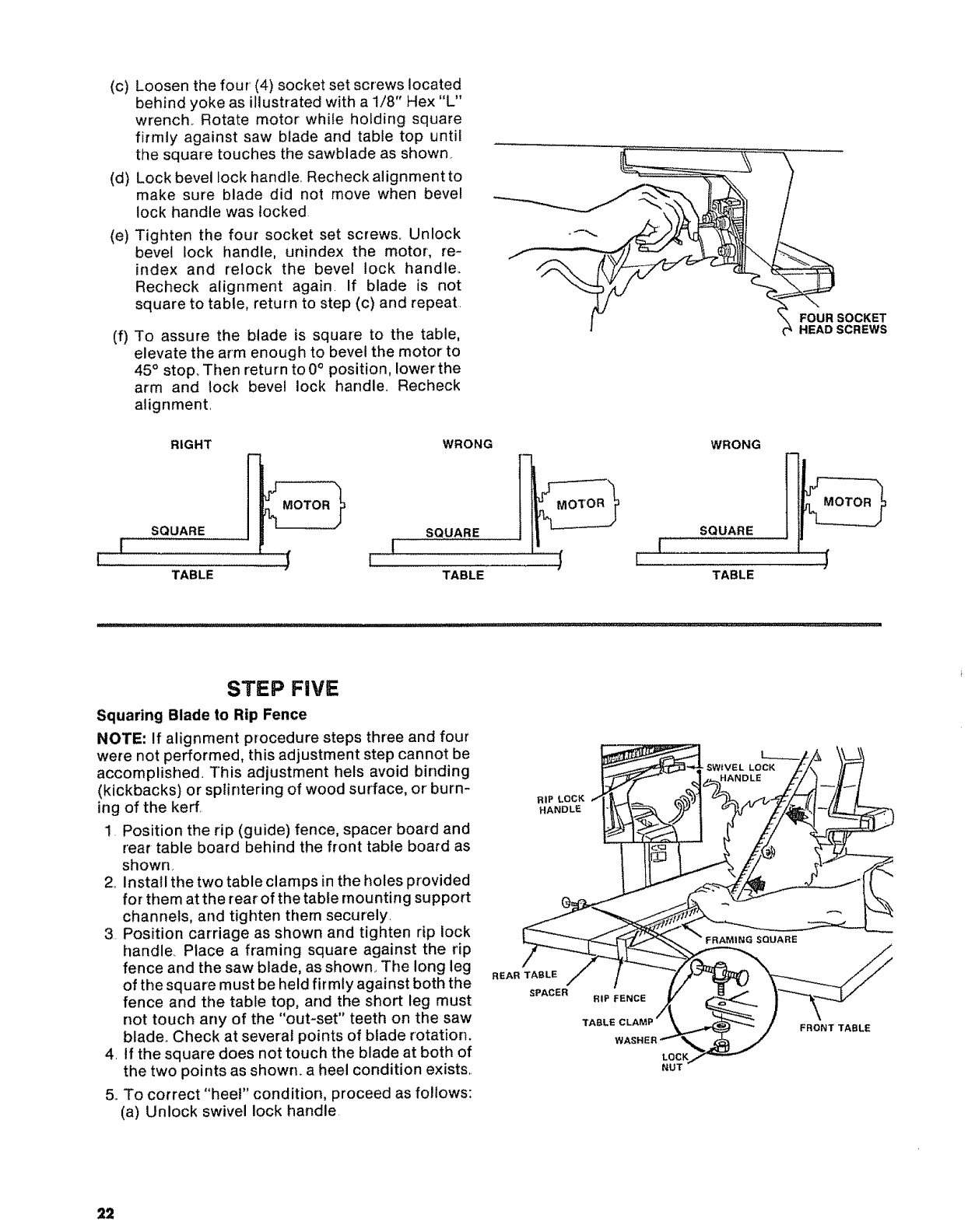
(c) Loosen the four' (4) socket set screws located
behind yoke as illustrated with a 1/8" Hex "L"
wrench. Rotate motor while holding square
firmly against saw blade and table top until
the square touches the sawblade as shown.
(d) Lock bevel lock handle Recheck alignment to
make sure blade did not move when bevel
lock handle was locked
(e)
(f)
Tighten the four socket set screws. Unlock
bevel lock handle, unindex the motor, re-
index and relock the bevel lock handle..
Recheck alignment again. If blade is not
square to table, return to step (c) and repeat.
To assure the blade is square to the table,
elevate the arm enough to bevel the motor to
45°stop_ Then return to 0°position, lower the
arm and lock bevel lock handle. Recheck
alignment.
¢_FOUR SOCKET
HEAD SCREWS
RIGHT WRONG WRONG
....,
l"ill 'f I................ (
TABLE "TABLE "
SQUARE
TABLE
STEP FiVE
Squaring Blade to Rip Fence
NOTE: If alignment procedure steps three and four
were not performed, this adjustment step cannot be
accomplished, This adjustment hels avoid binding
(kickbacks) or splintering of wood surface, or burn-
ing of the kerf,
1 Position the rip (guide) fence, spacer board and
rear table board behind the front table board as
shown
2o install the two table clamps in the holes provided
for them at the rear of the table rnounting support
channels, arid tighten them securely.
3. Position carriage as shown and tighten rip lock
handler Place a framing square against the rip
fence and the saw blade, as shown_ The long leg
of the square must be held firmly against both the
fence and the table top, and the short leg must
riot touch any of the "out-set" teeth on the saw
blade., Check at several points of blade rotation.
4. tf the square does not touch the blade at both of
the two points as shown, a heel condition exists,.
5.. To correct "heel" condition, proceed as follows:
(a) Unlock swivel lock handle
RIP LOCK
HANDLE
REAR TABLE
SPACER RIP FENCE
TABLE
LOCK
NUT
FRONT TABLE
22
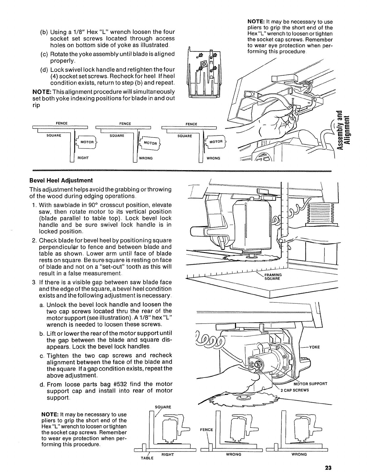
(b) Using a 1/8" Hex "L" wrench loosen the four
socket set screws located through access
holes on bottom side of yoke as illustrated.
(c) Rotate the yoke assembly until blade is aligned
properly.,
(d) Lock swivel lock handleand retighten the four
(4) socket set screw& Recheck for heel if heel
condition exists, return to step (b) and repeat.
NOTE: This alignment procedure will simultaneously
set both yoke indexing positions for blade in and out
rip
NOTE: tt may be necessary to use
pliers to grip the short end of the
Hex "L" wrench to loosen or tighten
the socket cap screws° Remember
to wear eye protection when per-
forming this procedure,
FENCE FENCE
SQUARE _SQUARE
jRIGHT
FENCE
UWRONG
(
Bevel Heel Adjustment
This adjustment helps avoid the grabbing or throwing
of the wood during edging operations,
1oWith sawblade in 90° crosscut position, elevate
saw, then rotate motor to its vertical position
(blade parallel to table top)., Lock bevel lock
handle and be sure swivel lock handle is in
locked position_
2,,Check blade for bevel heel by positioning square
perpendicular to fence and between blade and
table as shown. Lower arm until face of blade
rests on square, Be sure square is resting on face
of blade and not on a "set-out" tooth as this will
result in a false measurement,
3 If there is a visible gap between saw blade face
and the edge of the square, a bevel heel condition
exists and t_hefollowing adjustment is necessary.
a. Unlock the bevel lock handle and loosen the
two cap screws located thru the rear of the
motor support (see illustration). A 1/8" hex "L"
wrench is needed to loosen these screws..
b. Lift or lower the rear of the motor support until
the gap between the blade and square dis-
appears., Lock the bevel lock handles
c. Tighten the two cap screws and recheck
alignment between the face of the blade and
the square. If a gap condition exists, repeat the
above adjustment.
d. From loose parts bag #532 find the motor
support cap and install into rear of motor
support,
NOTE: It may be necessary to use
pliers to grip the short end of the
Hex"L" wrench to loosen or tighten
the socket cap screws. Remember
to wear eye protection when per-
forming this procedure,
SQUARE
TABLE WRONG WRONG
23
7= E
,==:
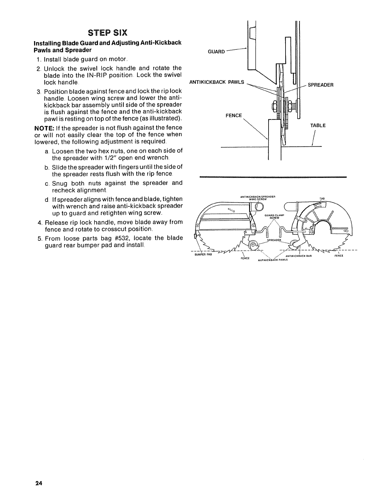
STEP SiX
Installing Blade Guard and Adjusting Anti-Kickback
Pawls and Spreader
1._Instatl blade guard on motor.
2. Unlock the swivel lock handle and rotate the
blade into the IN-RIP position Lock the swivel
lock handle
3. Position blade against fence and lock the rip lock
handle, Loosen wing screw and lower the anti-
kickback bar assembly until side of the spreader
is flush against the fence and the anti-kickback
pawl is resting on top of the fence (as illustrated).
NOTE: If the spreader is not flush against the fence
or will not easily clear the top of the fence when
lowered, the following adjustment is required
a Loosen the two hex nuts, one on each side of
the spreader with 1/2" open end wrench
b_ Slide the spreaderwith fingers until the side of
the spreader rests flush with the rip fence.
c, Snug both nuts against the spreader and
recheck alignment.
d If spreader aligns with fence and blade, tighten
with wrench and raise anti-kickback spreader
up to guard and retighten wing screw..
4.. Release rip lock handle, move blade away from
fence and rotate to crosscut position
5.. From loose parts bag #532, locate the blade
guard rear bumper pad and install
GUARD---'-'-'-_
ANT1KICKBACK PAWLS
FENCE
TABLE
A_T_(+_:Kg ACK t5PREADER
24
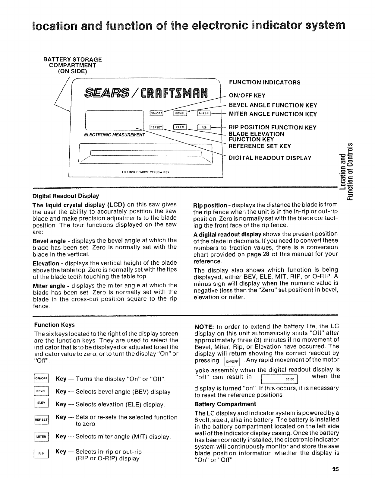
tocation and function of the electronic indicator system
BATTERY STORAGE
COMPARTMENT
(ON SIDE)
TO LOCK REMOVE V_LLOW KEY
FUNCTION INDICATORS
ON/OFF KEY
BEVEL ANGLE FUNCTION KEY
MITER ANGLE FUNCTION KEY
RIP POSITION FUNCTION KEY
BLADE ELEVATION
FUNCTION KEY
REFERENCE SET KEY
DIGITAL READOUT DISPLAY
Digital Readout Display
The liquid crystal display (LCD) on this saw gives
the user the ability to accurately position the saw
blade and make precision adjustments to the blade
position. The four functions displayed on the saw
are:
Bevel angle - displays the bevel angle at which the
blade has been set.. Zero is normally set with the
blade in the vertical..
Elevation - displays the vertical height of the blade
above the table top. Zero is normally set with the tips
of the blade teeth touching the table top
Miter angle - displays the miter angle at which the
blade has been set. Zero is normally set with the
blade in the cross-cut position square to the rip
fence.
Function Keys
The six keys located to the right of the display screen
are the function keys. They are used to select the
indicator that is to be displayed or adjusted to set the
indicator value to zero, or to turn the display "On" or
"Off"
Rip position - displays the distance the blade is from
the rip fence when the unit is in the in-rip or out-rip
position. Zero is normally set with the blade contact-
ing the front face of the rip fence.
Adigital readout display shows the present position
of the blade in decimals._ If you need to convert these
numbers to fraction vatues, there is a conversion
chart provided on page 28 of this manual for your
reference.
The display also shows which function is being
displayed, either BEV, ELE, MIT, RIP, or O-RIP A
minus sign will display when the numeric value is
negative (less than the "Zero" set position) in bevel,
elevation or miter..
NOTE: In order to extend the battery life, the LC
display on this unit automatically shuts "Off" after
approximately three (3) minutes if no movement of
Bevel, Miter, Rip, or Elevation have occurred The
display will return showing the correct readout by
pressing _ Any rapid movement of the motor
Key -- Turns the display "On" or "Off".
Key -- Selects bevel angle (BEV) display
Key -- Selects elevation (ELE) dispfay_
Key -- Sets or re-sets the selected function
to zero.
Key -- Selects miter angle (MIT) display
Key m Selects in-rip or out-rip
(RIP or O-RIP) display
yoke assembly when the digital readout display is
"off" can result in ! _E_E] when the
display is turned "on" If this occurs, it is necessary
to reset the reference positions.
Battery Compartment
The LC display and indicator system is powered by a
6 volt, size J, aEkaline battery, The battery is installed
in the battery compartment located on the left side
wall of the indicator display casing.. Once the battery
has been correctly installed, the electronic indicator
system will continuously monitor and store the saw
blade position information whether the display is
"On" or "Off"
25
eo_-
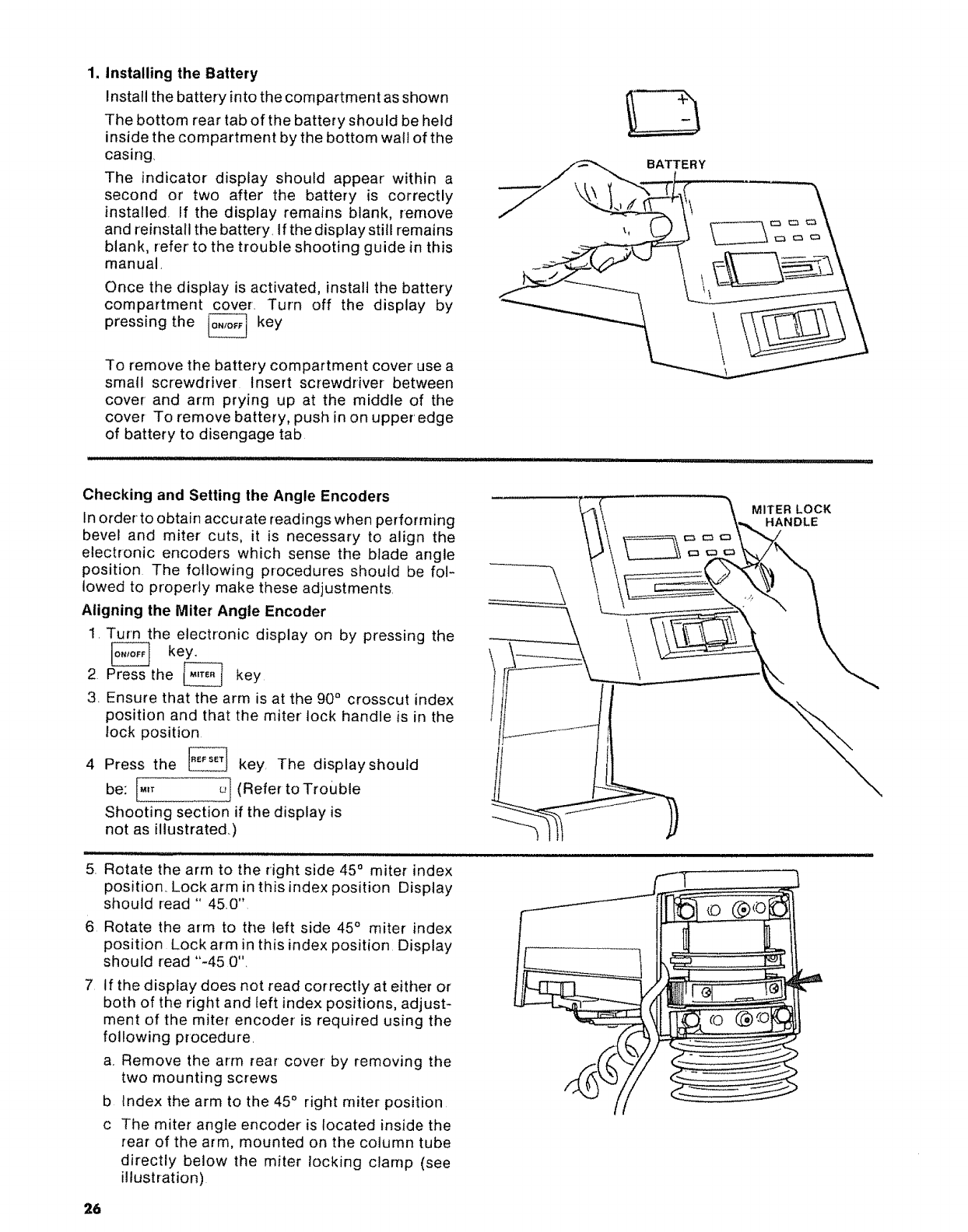
1. Installing the Battery
Install the battery into the compartment as shown
The bottom rear tab of the battery should be held
inside the compartment by the bottom wall of the
casing,
The indicator display should appear within a
second or two after the battery is correctly
installed, if the display remains blank, remove
and reinstall the battery. If the display still remains
blank, refer to the trouble shooting guide in this
manual,
Once the display is activated, install the battery
compartment cover. Turn off the display by
pressing the _ key
L_J
To remove the battery compartment cover use a
small screwdriver Insert screwdriver between
cover and arm prying up at the middle of the
cover To remove battery, push in on upper' edge
of battery to disengage tab
BATTERY
Checking and Setting the Angle Encoders
In order to obtain accurate readings when performing
bevel and miter cuts, it is necessary to align the
electronic encoders which sense the blade angle
position The following procedures should be fol-
lowed to properly make these adjustments,
Aligning the Miter Angle Encoder
1, Turn the electronic display on by pressing the
_ key.
2 Press the t,_,TE.I key
3. Ensure that the arm is at the 90 °crosscut index
position and that the miter lock handle is in the
lock position
4 Press the | key, The display should
be: _,T _'1(Refer toTrouble
Shooting section if the display is
not as illustrated.)
MITER LOCK
HANDLE
5, Rotate the arm to the right side 45° miter index
position,. Lock arm in this index position Display
should read " 45,0"
6 Rotate the arm to the left side 45° miter index
position Lock arm in this index position Display
should read "-45 0"_
7 If the display does not read correctly at either or
both of the right and left index positions, adjust-
ment of the miter encoder is required using the
following procedure,
a,, Remove the arm rear cover by removing the
two mounting screws
b Index the arm to the 45 °right miter position
c The miter angle encoder is located inside the
rear of the arm, mounted on the column tube
directly below the miter locking clamp (see
illustration)
26
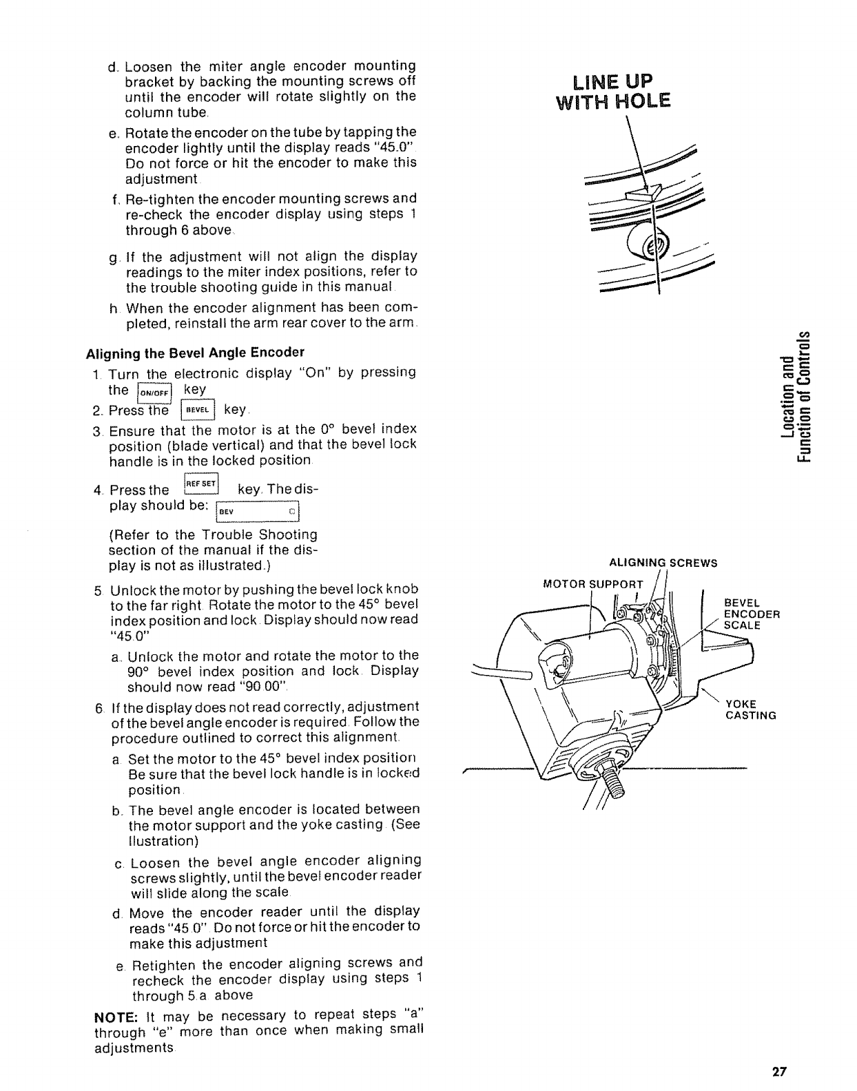
d., Loosen the miter angle encoder mounting
bracket by backing the mounting screws off
until the encoder will rotate slightly on the
column tube,
e,,Rotate the encoder on the tube by tapping the
encoder lightly until the display reads "450"
Do not force or hit the encoder to make this
adjustment
f,, Re4ighten the encoder mounting screws and
re-check the encoder display using steps 1
through 6 above
g, If the adjustment will not align the display
readings to the miter index positions, refer to
the trouble shooting guide in this manual
h When the encoder alignment has been com-
pleted, reinstall the arm rear cover to the arm,
Aligning the Bevel Angle Encoder
1. Turn the electronic display "On" by pressing
the _ _key
2, Press the _ key,
3. Ensure that the motor is at the 0° bevel index
position (blade vertical) and that the bevel lock
handle is in the locked position
4. Press the _ key, The dis-
play should be: I_Ev _,..1
(Refer to the Trouble Shooting
section of the manual if the dis-
play is not as illustrated,)
5 Unlock the motor by pushing the bevel lock knob
to the far right Rotate the motor to the 45° bevel
index position and lock Display should now read
"450"
a, Unlock the motor and rotate the motor to the
90° bevel index position and lock Display
should now read "9000",
6 If the display does not read correctly, adjustment
of the bevel angle encoder is required, Follow the
procedure outlined to correct this alignment,
a Set the motor to the 45 ° bevel index position
Be sure that the bevel lock handle is in locked
position
b, The bevel angle encoder is located between
the motor support and the yoke casting (See
llustration)
c, Loosen the bevel angle encoder aligning
screws slightly, until the bevel encoder reader
will slide along the scale
d Move the encoder reader until the display
reads "45,0" Do not force or hit the encoder to
make this adjustment
e Retighten the encoder aligning screws and
recheck the encoder display using steps 1
through 5,a above
NOTE: It may be necessary to repeat steps "a"
through "e" more than once when making small
adjustments
LINE UP
WITH HOLE
ALIGNING SCREWS
MOTOR SUPPORT
6O
...J €._
p.
BEVEL
ENCOOER
SCALE
YOKE
CASTING
27
f ff the adjustment will not align the display
readout to the bevel index positions, refer to
the trouble shooting guide in this manual
g, When the encoder alignment has been com-
pleted, the electronic indicator' system should
be ready for use.
Using the Electronic Indicator System
1. Setting the indicator reference points.
In order to establish the starting location point of
the blade, it is necessary to set the indicator
references at zero. Normally, these zero refer-
ences are the front of the fence, the top of the
table, and with the face of the blade square to
both of these surfaces However, many instances
wilt require selection of the reference points to fit
the woodworking operations to be performed,
Place the blade or cutting toot in the exact
position and angle that you have selected as the
zero reference position
Turn the display "On" by pressing _ key.
Press the _ angle function key. Press
to set the zero reference angle for' the
bevel readout
This display should read: _ D}
Press the _ key Press _ to set the
zero reference angle for the miter readout
This display should read: [.,. D]
Press the _ key, Press _tosetthezero
reference location for the blade elevation
readout
This display should read: [_LE U_ i
Press [_ key Press _ to set the
zero reference location for in-rip. The indicator
display should read: _ _r._]
If"O-Rip" is displayed, press [_ again.
Before pressing _ key to set the zero
reference location for the blade in-rip location
readout.
The display should now read: l.,_ _ o ]
Press the _ key again, The "O-Rip"
indicator display should now appear. Press
, the display should read: Eo,,.,P D_ ]
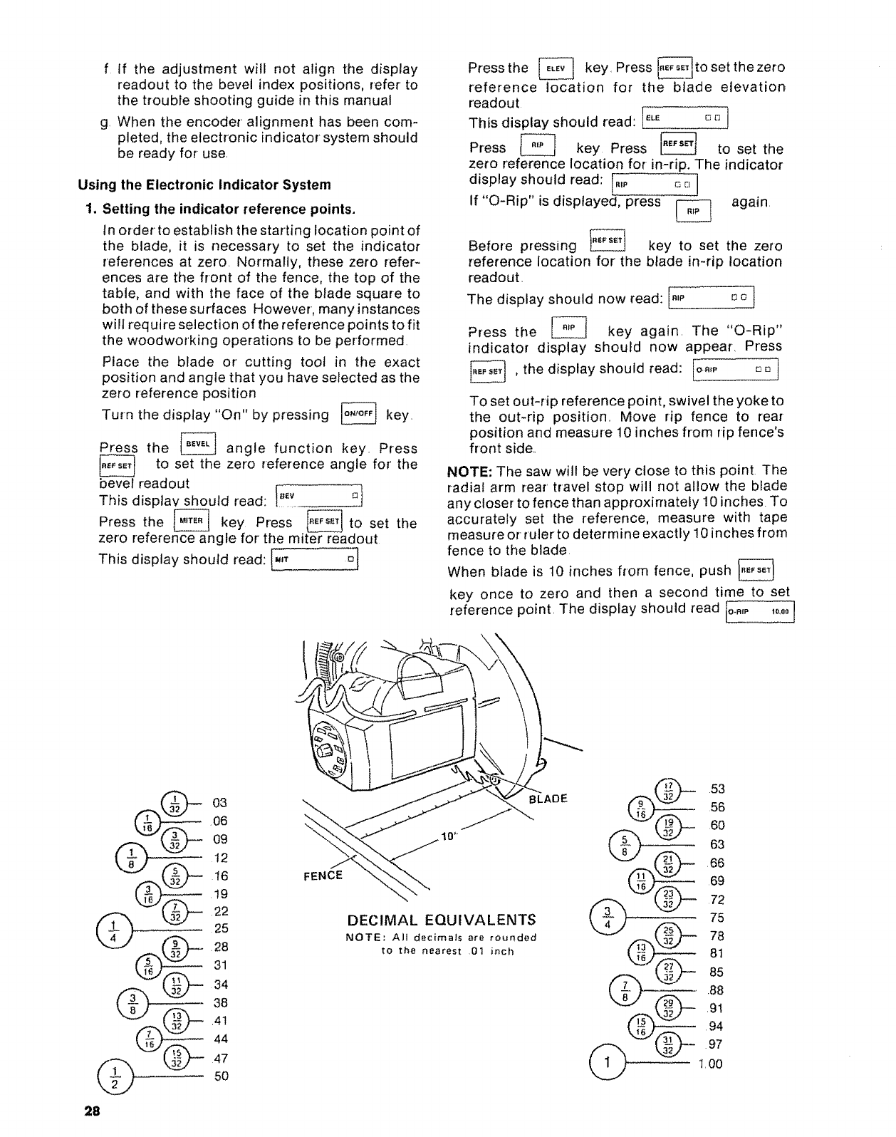
To set out-rip reference point, swivel the yoke to
the out-rip position,, Move rip fence to rear
position and measure 10 inches from rip fence's
front side,.
NOTE: The saw will be very close to this point, The
radial arm rear travel stop will not allow the blade
any closer to fence than approximately 10 inches. To
accurately set the reference, measure with tape
measure or ruler to determine exactly 10 inches from
fence to the blade
When blade is 10 inches from fence, push
key once to zero and then a second time to set
reference point, The display should read Io..,p 1o_0o]
03
,06
09
12
__ 16
,19
22
25
•4.__ .2831
38
44
4"7
5O
FENCE
BLAOE
DECIMAL EQUIVALENTS
NOTE; All decimals are rounded
to the nearest 01 inch
53
56
60
63
66
69
72
75
78
81
85
88
,9t
94
97
1,00
28
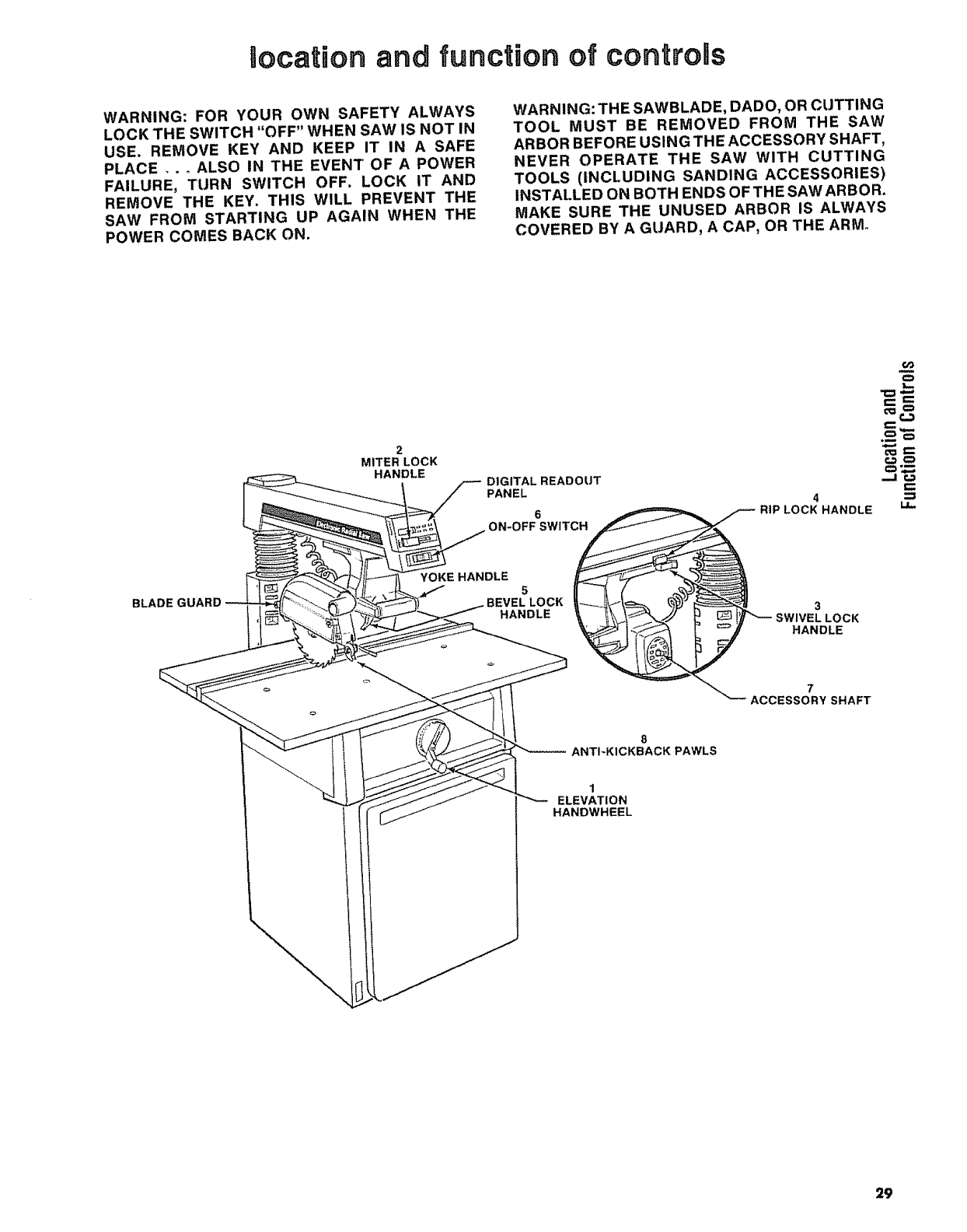
Uocation and function of controns
WARNING: FOR YOUR OWN SAFETY ALWAYS
LOCK THE SWITCH "OFF" WHEN SAW IS NOT IN
USE. REMOVE KEY AND KEEP IT IN A SAFE
PLACE,,, ALSO IN THE EVENT OF A POWER
FAILURE, TURN SWITCH OFF, LOCK IT AND
REMOVE THE KEY. THIS WILL PREVENT THE
SAW FROM STARTING UP AGAIN WHEN THE
POWER COMES BACK ON.
WARNING: THE SAWBLADE, DADO, OR CUTTING
TOOL MUST BE REMOVED FROM THE SAW
ARBOR BEFORE USING THE ACCESSORY SHAFT,
NEVER OPERATE THE SAW WITH CUTTING
TOOLS (INCLUDING SANDING ACCESSORIES)
INSTALLED ON BOTH ENDS OF THE SAW ARBOR.
MAKE SURE THE UNUSED ARBOR IS ALWAYS
COVERED BY A GUARD, A CAP, OR THE ARM°
2
MITER LOCK
HANDLE DIGITAL READOUT
PANEL 4
RIP LOCK HANDLE
¢o
e- I:=:
_€.,3
.-J¢_
BLADE GUARD
YOKE HANDLE 5
BEVEL LOCK
HANDLE
8
ANTI-KICKBACK PAWLS
1
ELEVATfON
HANDWHEEL
3
EL LOCK
HANDLE
7
ACCESSORY SHAFT
29
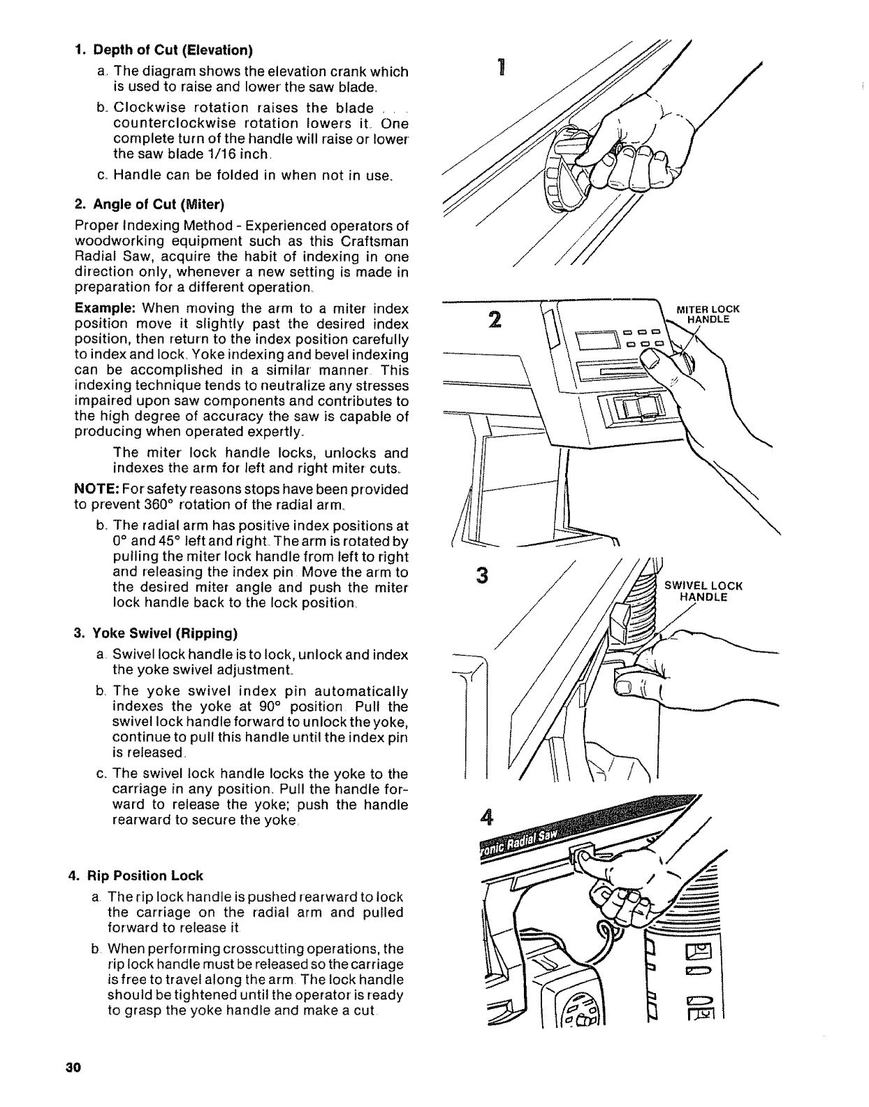
1. Depthof Cut(Elevation)
aThe diagram shows the elevation crank which
is used to raise and lower' the saw blade..
boCiockwise rotation raises the blade _.
counterclockwise rotation lowers iL One
complete turn of the handle will raise or lower
the saw blade 1/16 inch.
c_ Handle can be folded in when not in use.
2. Angle of Cut (Miter)
Proper Indexing Method -Experienced operators of
woodworking equipment such as this Craftsman
Radial Saw, acquire the habit of indexing in one
direction only, whenever a new setting is made in
preparation for a different operation
Example: When moving the arm to a miter index
position move it slightly past the desired index
position, then return to the index position carefully
to index and lock Yoke indexing and bevel indexing
can be accomplished in a similar' manner This
indexing technique tends to neutralize any stresses
impaired upon saw components and contributes to
the high degree of accuracy the saw is capable of
producing when operated expertly..
The miter lock handle locks, unlocks and
indexes the arm for left and right miter cuts.
NOTE: For safety reasons stops have been provided
to prevent 360 °rotation of the radial arm
b..The radial arm has positive index positions at
0°and 45° left arid right._The arm is rotated by
pulling the miter lock handle from left to right
arid releasing the index pin Move the arm to
the desired miter angle and push the miter
lock handle back to the lock position.
3. Yoke Swivel (Ripping)
a Swivel lock handle is to lock, unlock and index
the yoke swivel adjustmenL
b, The yoke swivel index pin automatically
indexes the yoke at 90° position Pull the
swivel lock handle forward to unlock the yoke,
continue to pull this handle until the index pin
is released.
C_ The swivel lock handle locks the yoke to the
carriage in any position. Pull the handle for-
ward to release the yoke; push the handle
rearward to secure the yoke.
4. Rip Position Lock
a The rip lock handle is pushed rearward to lock
the carriage on the radial arm and pulled
forward to release it
b When performing crosscutting operations, the
rip lock handle must be released so the carriage
is free to travel along the arm The lock handle
should be tightened until the operator' is ready
to grasp the yoke handle and make a cut
8O
2
3
4
MITER LOCK
SWIVEL LOCK
HANDLE
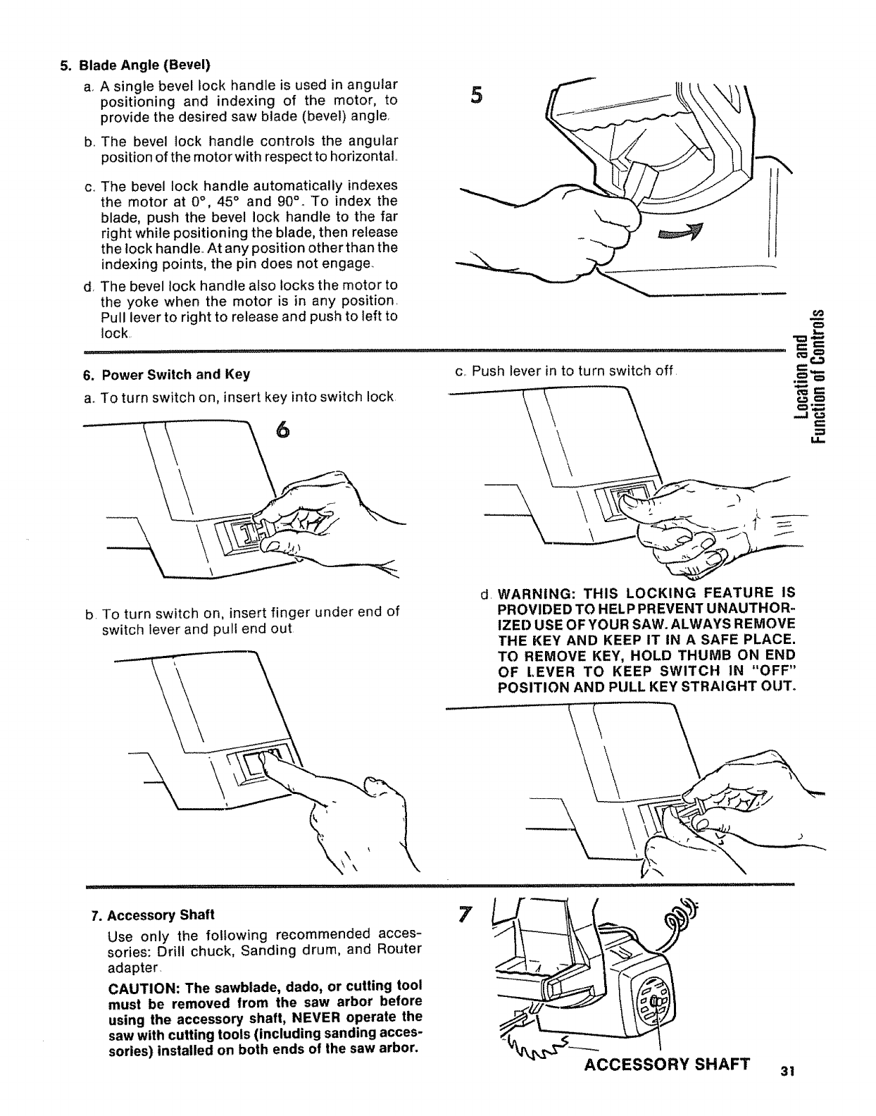
5. Blade Angle (Bevel)
a_A single bevel lock handle is used in angular
positioning and indexing of the motor, to
provide the desired saw blade (bevel) angle.
boThe bevel lock handle controls the angular
position of the motor with respect to horizontal..
C_,
d,
5
The bevel lock handle automatically indexes
the motor at 0°, 45° and 90° .To index the
blade, push the bevel lock handle to the far
right while positioning the blade, then release
the lock handle.. At any position other than the
indexing points, the pin does not engage.
The bevel lock handle also locks the motor to
the yoke when the motor is in any position.
Pull lever to right to release and push to left to
lock. _--
Power Switch and Key
To turn switch on, insert key into switch lock.
c.. Push lever in to turn switch off
.
a°
b. To turn switch on, insert finger under end of
switch lever and pull end out
dWARNING: THIS LOCKING FEATURE iS
PROVIDED TO HELP PREVENT UNAUTHOR-
IZED USE OF YOUR SAW. ALWAYS REMOVE
THE KEY AND KEEP IT IN A SAFE PLACE.
TO REMOVE KEY, HOLD THUMB ON END
OF [.EVER TO KEEP SWITCH IN "OFF"
POSITION AND PULL KEY STRAIGHT OUT.
\\
7. Accessory Shaft
Use only the following recommended acces-
sories: Drill chuck, Sanding drum, and Router
adapter.
CAUTION: The sawblade, dado, or cutting tool
must be removed from the saw arbor before
using the accessory shaft, NEVER operate the
saw with cutting tools (including sanding acces-
sories) installed on both ends of the saw arbor.
7
ACCESSORY SHAFT 31
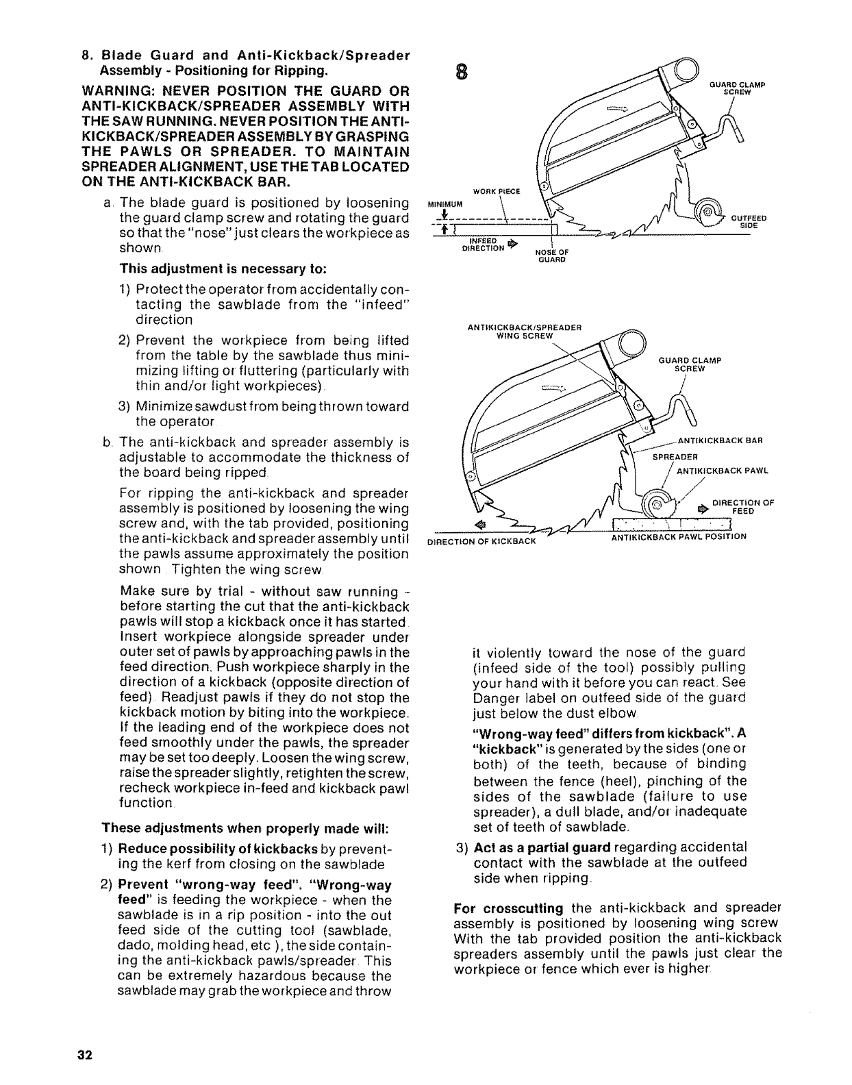
8. Blade Guard and Anti-Kickback/Spreader
Assembly-Positioning for Ripping.
WARNING: NEVER POSITION THE GUARD OR
ANTI-KICKBACK/SPREADER ASSEMBLY WITH
THE SAW RUNNING, NEVER POSITION THE ANTI-
KICKBACK/SPREADER ASSEMBLY BY GRASPING
THE PAWLS OR SPREADER. TO MAINTAIN
SPREADER ALIGNMENT, USE THE TAB LOCATED
ON THE ANTI-KICKBACK BAR.
a. The blade guard is positioned by loosening
the guard clamp screw and rotating the guard
so that the "nose" just clears the workpiece as
shown
This adjustment is necessary to:
1) Protect the operator from accidenta!ly con-
tacting the sawbtade from the "infeed"
direction
b_
2) Prevent the workpiece from being lifted
from the table by the sawblade thus mini-
mizing lifting or fluttering (particularly with
thin and/or light workpieces).
3) Minimize sawdust from being thrown toward
the operator
The anti-kickback and spreader assembly is
adjustable to accommodate the thickness of
the board being ripped.
For ripping the anti-kickback and spreader
assembly is positioned by loosening the wing
screw and, with the tab provided, positioning
the anti-kickback and spreader assembly until
the pawls assume approximately the position
shown Tighten the wing screw
Make sure by trial - without saw running -
before starting the cut that the anti-kickback
pawls will stop a kickback once it has started
Insert workpiece alongside spreader under
outer' set of pawls by approaching pawls in the
feed direction, Push workpiece sharply in the
direction of a kickback (opposite direction of
feed) Readjust pawls if they do not stop the
kickback motion by biting into the workpiece.
If the leading end of the workpiece does not
feed smoothly under the pawls, the spreader
may be set too deeply. Loosen the wing screw,
raise the spreader slightly, retighten the screw,
recheck workpiece in-feed and kickback pawl
function,
These adjustments when properly made will:
1) Reduce possibility of kickbacks by prevent-
ing the kerf from closing on the sawblade
2) Prevent "wrong-way feed'L "Wrong-way
feed" is feeding the workpiece - when the
sawblade is in a rip position -into the out
feed side of the cutting toot (sawbtade,
dado, molding head, etc ), the side contain-
ing the anti-kickback pawls/spreader This
can be extremely hazardous because the
sawblade may grab the workpiece and throw
8GUARD CLAMP
SCREW
NOSEOF
GUARD
OUTFEED
SIDE
ANTIKICKBACKiSPREADER
WING SCREW
GUARD CLAMP
SCREW
DIRECTION OF KICKBACK
SPREADER
ANTIKICKBACK PAWL
/
_ DIRECTION OF
FEED
ANTIK|CKSACK PAWL POSITION
3)
it violently toward the nose of the guard
(infeed side of the tool) possibly pulling
your hand with it before you can react. See
Danger label on outfeed side of the guard
just below the dust elbow.
"Wrong-way feed" differs from kickback". A
"kickback" is generated by the sides (one or
both) of the teeth, because of binding
between the fence (heel), pinching of the
sides of the sawblade (failure to use
spreader), a dull blade, and/or inadequate
set of teeth of sawblade..
Act as a partial guard regarding accidental
contact with the sawblade at the outfeed
side when ripping..
For crosscutting the anti-kickback and spreader
assembly is positioned by loosening wing screw
With the tab provided position the anti-kickback
spreaders assembly until the pawls just clear the
workpiece or fence which ever is higher
32
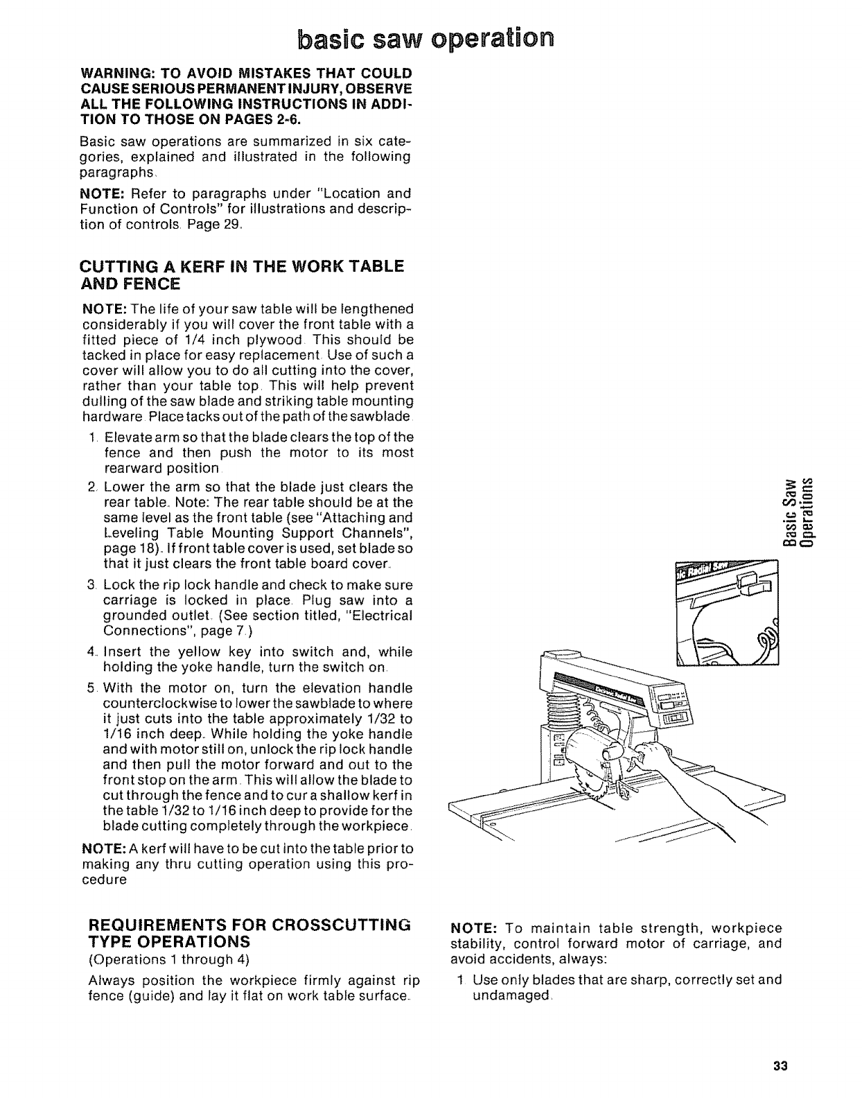
basic saw operation
WARNING: TO AVOID MISTAKES THAT COULD
CAUSE SERIOUS PERMANENT INJURY, OBSERVE
ALL THE FOLLOWING INSTRUCTIONS IN ADDI-
TION TO THOSE ON PAGES 2-6.
Basic saw operations are summarized in six cate-
gories, explained and illustrated in the following
paragraphs
NOTE: Refer to paragraphs under "Location and
Function of Controls" for illustrations and descrip-
tion of controls. Page 29,,
CUTTING A KERF IN THE WORK TABLE
AND FENCE
NOTE: The life of your saw table will be lengthened
considerably if you will cover the front table with a
fitted piece of 1/4 inch plywood. This should be
tacked in place for easy replacement Use of such a
cover will allow you to do all cutting into the cover,
rather than your table top. This will help prevent
dulling of the saw blade and striking table mounting
hardware Place tacks out of the path of the sawblade
1. Elevate arm so that the blade clears the top of the
fence and then push the motor to its most
rearward position
2, Lower the arm so that the blade just clears the
rear table., Note: The rear table should be at the
same level as the front table (see "Attaching and
Leveling Table Mounting Support Channels",
page 18)..If front table cover is used, set blade so
that it just clears the front table board cover,.
3. Lock the rip lock handle and check to make sure
carriage is locked in place. Plug saw into a
grounded outlet, (See section titled, "Electrical
Connections", page 7.)
4.. insert the yellow key into switch and, while
holding the yoke handle, turn the switch on.
5. With the motor on, turn the elevation handle
counterclockwise to lower the sawblade to where
it just cuts into the table approximately 1/32 to
1/16 inch deep.. While holding the yoke handle
and with motor still on, unlock the rip lock handle
and then pull the motor forward and out to the
front stop on the arm. This will allow the blade to
cut through the fence and to cur a shallow kerf in
the table t/32 to 1/16 inch deep to provide for the
blade cutting completely through the workpiece.
NOTE: A kerf will have to be cut into the table prior to
making any thru cutting operation using this pro-
cedure
oO
o=l
r,,O_
r_
REQUIREMENTS FOR CROSSCUTTING
TYPE OPERATIONS
(Operations 1 through 4)
Always position the workpiece firmly against rip
fence (guide) and lay it flat on work table surface..
NOTE: To maintain table strength, workpiece
stability, control forward motor of carriage, and
avoid accidents, always:
1 Use only blades that are sharp, correctly set and
undamaged,
33
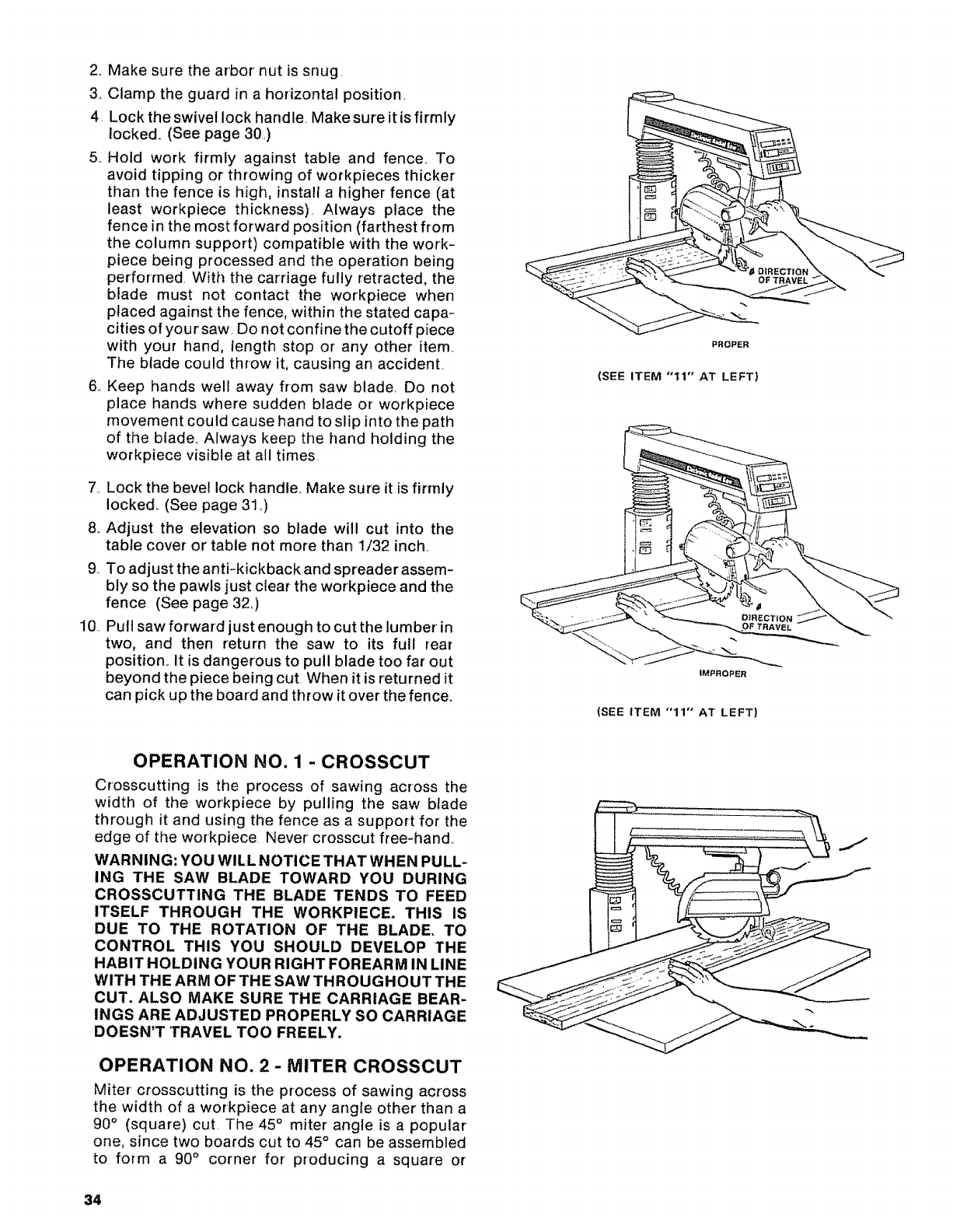
2. Make sure the arbor nut is snug.
3. Clamp the guard in a horizontal position.
4. Lock the swivel lock handle Make sure it is firmly
locked. (See page 30)
5_ Hold work firmly against table and fence. To
avoid tipping or throwing of workpieces thicker
than the fence is high, install a higher fence (at
least workpiece thickness). Always place the
fence in the most forward position (farthest from
the column support) compatible with the work-
piece being processed and the operation being
performed With the carriage fully retracted, the
blade must not contact the workpiece when
placed against the fence, within the stated capa-
cities of your saw. Do not confine the cutoff piece
with your hand, length stop or any other item..
The blade could throw it, causing an accident.
6.. Keep hands well away from saw blade. Do not
place hands where sudden blade or workpiece
movement could cause hand to slip into the path
of the blade, Always keep the hand holding the
workpiece visible at all times.
7_ Lock the bevel lock handte., Make sure it is firrnly
locked. (See page 31..)
8_ Adjust the elevation so blade will cut into the
table cover- or table not more than 1/32 inch
9. To adjust the anti-kickback and spreader assem-
bly so the pawls just ctear the workpiece and the
fence (See page 32_)
10.. Pull saw forward just enough to cut the lumber in
two, and then return the saw to its ful! rear
position° It is dangerous to pull blade too far out
beyond the piece being cut. When it is returned it
can pick up the board and throw it over the fence.
OPERATION NO. 1 - CROSSCUT
Crosscutting is the process of sawing across the
width of the workpiece by pulling the saw blade
through it and using the fence as a support for the
edge of the workpiece, Never crosscut free-hand..
WARNING: YOU WILL NOTICE THAT WHEN PULL-
ING THE SAW BLADE TOWARD YOU DURING
CROSSCUTTING THE BLADE TENDS TO FEED
ITSELF THROUGH THE WORKPIECE. THIS IS
DUE TO THE ROTATION OF THE BLADE, TO
CONTROL THIS YOU SHOULD DEVELOP THE
HABIT HOLDING YOUR RIGHT FOREARM IN LINE
WITH THE ARM OF THE SAW THROUGHOUT THE
CUT. ALSO MAKE SURE THE CARRIAGE BEAR-
INGS ARE ADJUSTED PROPERLY SO CARRIAGE
DOESN'T TRAVEL TOO FREELY,
OPERATION NO. 2 - MITER CROSSCUT
Miter crosscutting is the process of sawing across
the width of a workpiece at any angle other than a
90° (square) cut. The 45° miter angle is a popular
one, since two boards cut to 45°can be assembled
to form a 90 ° corner for producing a square or
34
PROPER
(SEE ITEM "11" AT LEFT)
iMPROPER
(SEE ITEM '°11" AT LEFT)
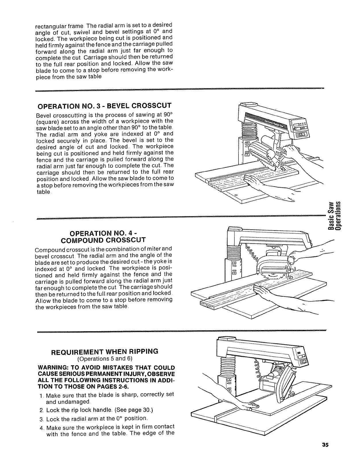
rectangular frame The radial arm is set to a desired
angle of cut, swivel and bevel settings at 0° and
locked. The workpiece being cut is positioned and
held firmly against the fence and the carriage pulled
forward along the radial arm just far enough to
complete the cut Carriage should then be returned
to the full rear position and locked,. Allow the saw
blade to come to a stop before removing the work-
piece from the saw table
OPERATION NO. 3 - BEVEL CROSSCUT
Bevel crosscutting is the process of sawing at 90°
(square) across the width of a workpiece with the
saw blade set to an angle other than 90° to the table,
The radial arm and yoke are indexed at 0° and
locked securely in place,, The bevel is set to the
desired angle of cut and locked. The workpiece
being cut is positioned and held firmly against the
fence and the carriage is pulled forward along the
radial arm just far enough to complete the cut. The
carriage should then be returned to the ful! rear
position and locked, Allow the saw blade to come to
a stop before removing the workpieces from the saw
table
OPERATION NO. 4 -
COMPOUND CROSSCUT
Compound crosscut is the combination of miter and
bevel crosscut The radial arm and the angle of the
blade are set to produce the desired cut- the yoke is
indexed at 0° and locked The workpiece is posi-
tioned and held firmly against the fence and the
carriage is pulled forward along the radial arm just
far enough to complete the cut The carriage should
then be returned to the full rear position and locked.
Allow the blade to come to a stop before removing
the workpieces from the saw table,
REQUIREMENT WHEN RIPPING
(Operations 5 and 6)
WARNING: TO AVOID MISTAKES THAT COULD
CAUSE SERIOUS PERMANENT INJURY, OBSERVE
ALL THE FOLLOWING INSTRUCTIONS IN ADDI_
TION TO THOSE ON PAGES 2-6.
1 Make sure that the blade is sharp, correctly set
and undamaged
2, Lock the rip lock handle, (See page 3&)
3, Lock the radial arm at the 0° position,,
4, Make sure the workpiece is kept in firm contact
with the fence and the table., The edge of the
35
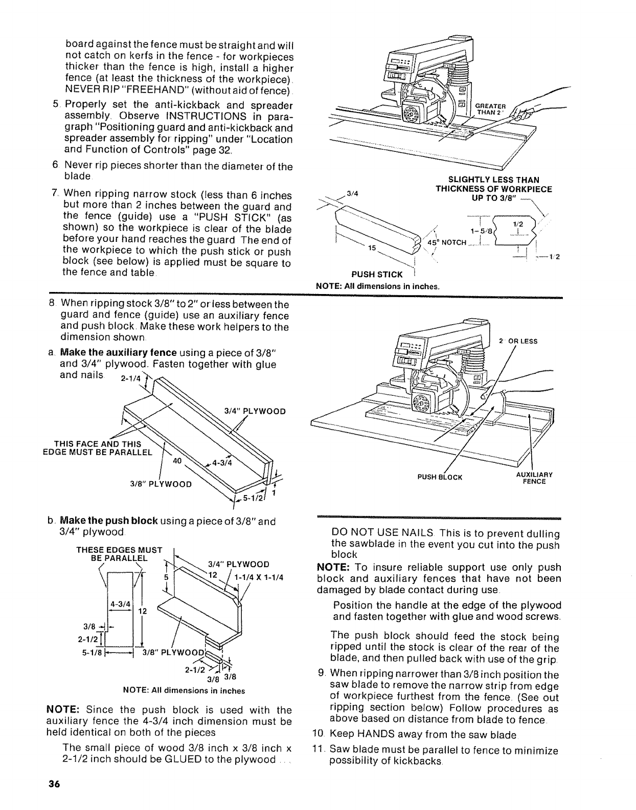
board against the fence must be straight and will
not catch on kerfs in the fence - for workpieces
thicker than the fence is high, install a higher
fence (at least the thickness of the workpiece).
NEVER RIP"FREEHAND" (without aid offence)
5 Properly set the anti-kickback and spreader
assernbly, Observe INSTRUCTIONS in para-
graph "Positioning guard and anti-kickback and
spreader assembly for ripping" under "Location
and Function of Controls" page 32.
6 Never rip pieces shorter than the diameter-of the
blade
7. When ripping narrow stock (tess than 6 inches
but more than 2 inches between the guard and
the fence (guide) use a "PUSH STICK" (as
shown) so the workpiece is clear of the blade
before your hand reaches the guard The end of
the workpiece to which the push stick or push
block (see below) is applied must be square to
the fence and table.
8. When ripping stock 3/8" to 2" or less between the
guard and fence (guide) use an auxiliary fence
and push block. Make these work helpers to the
dimension shown
3/4
SLIGHTLY LESS THAN
THICKNESS OF WORKPIECE
UP TO 3/8" --.
'i ---! i,--t2
2OR LESS
aMake the auxiliary fence using a piece of 3/8"
and 3/4" plywood.. Fasten together with glue
and nails 2-1
3/4" PLYWOOD
THIS FACE AND THIS
EDGE MUST BE PARALLEL
318" PLYWOOD
AUXILIARY
PUSH 9LOCK FENCE
b, Make the push block using a piece of 3/8" and
3/4" plywood.
THESE EDGES MUST
BE PARALLEL
5-1/8_ 3/8" PLYWOOD:
,YWOOD
1-1/4
2-112 318 318
NOTE: All dimensions in inches
NOTE: Since the push block is used with the
auxiliary fence the 4-3/4 inch dimension must be
held identical on both of the pieces
The small piece of wood 3/8 inch x 3/8 inch x
2-1/2 inch should be GLUED to the plywood ....
DO NOT USE NAILS This is to prevent dulling
the sawblade in the event you cut into the push
block
NOTE: To insure reliable support use only push
block and auxiliary fences that have not been
damaged by blade contact during use,
Position the handle at the edge of the plywood
and fasten together with glue and wood screws.
g.
10,
11.
The push block should feed the stock being
ripped until the stock is clear of the rear of the
blade, and then pulled back with use of the grip.
When ripping narrower than 3/8 inch position the
saw blade to rernove the narrow strip from edge
of workpiece furthest from the fence. (See out
ripping section below) Follow procedures as
above based on distance from blade to fence.
Keep HANDS away from the saw blade
Saw blade must be parallel to fence to minimize
possibility of kickbacks.
36
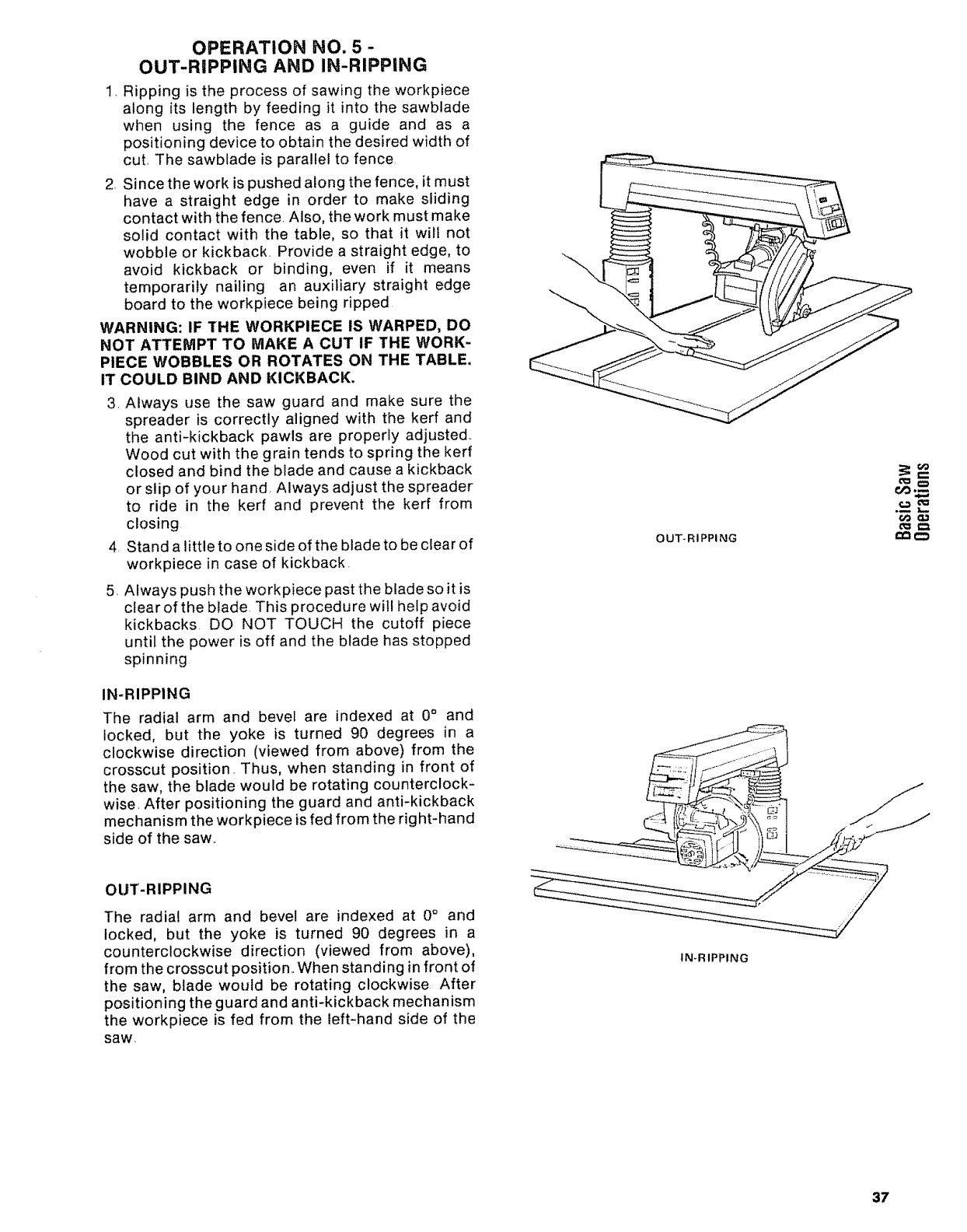
OPERATION NO. 5-
OUT-RIPPING AND IN-RIPPING
1. Ripping is the process of sawing the workpiece
along its length by feeding it into the sawblade
when using the fence as a guide and as a
positioning device to obtain the desired width of
cut. The sawblade is parallel to fence
2. Since the work is pushed along the fence, it must
have a straight edge in order to make sliding
contact with the fence. Also, the work must make
solid contact with the table, so that it will not
wobble or kickback. Provide a straight edge, to
avoid kickback or binding, even if it means
temporarily nailing an auxiliary straight edge
board to the workpiece being ripped
WARNING: IF THE WORKPIECE IS WARPED, DO
NOT ATTEMPT TO MAKE A CUT IF THE WORK-
PIECE WOBBLES OR ROTATES ON THE TABLE,
IT COULD BIND AND KICKBACK.
3. Always use the saw guard and make sure the
spreader is correctly aligned with the kerf and
the anti-kickback pawls are properly adjusted..
Wood cut with the grain tends to spring the kerr
closed and bind the blade and cause a kickback
or slip of your hand, Always adjust the spreader
to ride in the kerf and prevent the kerr from
closing
4 Stand a little to one side of the blade to be clear of
workpiece in case of kickback.
5. Always push the workpiece past the blade so it is
clear of the blade This procedure will help avoid
kickbacks. DO NOT TOUCH the cutoff piece
until the power is off and the blade has stopped
spinning
IN.RIPPING
The radial arm and bevel are indexed at 0° and
locked, but the yoke is turned 90 degrees in a
clockwise direction (viewed from above) from the
crosscut position. Thus, when standing in front of
the saw, the blade would be rotating counterclock-
wise. After positioning the guard and anti-kickback
mechanism the workpiece is fed from the right-hand
side of the saw..
OUT-RIPPING
oo__=
OUT-RIPPING
The radial arm and bevel are indexed at 0°and
locked, but the yoke is turned 90 degrees in a
counterclockwise direction (viewed from above),
from the crosscut position., When standing in front of
the saw, blade would be rotating clockwise After
positioning the guard and anti-kickback mechanism
the workpiece is fed from the teft-hand side of the
saw,
IN*RIPPING
37
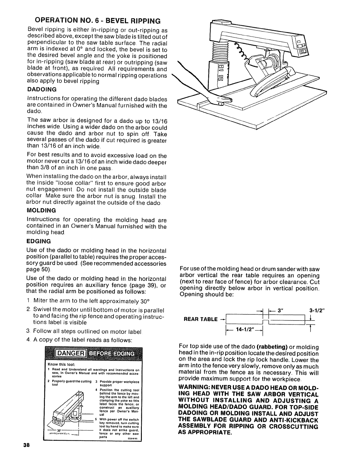
OPERATION NO. 6 - BEVEL RIPPING
Bevel ripping is either in-ripping or out-ripping as
described above, except the saw blade is tilted out of
perpendicular to the saw table surface The radial
arm is indexed at 0° and locked, the bevel is set to
the desired bevel angle and the yoke is positioned
for in=ripping (saw blade at rear) or outripping (saw
blade at front), as required All requirements and
observations applicable to normal ripping operations
also apply to bevel ripping
DADOING
Instructions for operating the different dado blades
are contained in Owner's Manual furnished with the
dado.
The saw arbor is designed for a dado up to 13/16
inches wide. Using a wider dado on the arbor could
cause the dado and arbor nut to spin off. Take
several passes of the dado if cut required is greater
than 13/16 of an inch wide
For best results and to avoid excessive load on the
motor never cut a 13/16 of an inch wide dado deeper
than 3/8 of an inch in one pass,
When installing the dado on the arbor, always install
the inside "loose collar" first to ensure good arbor
nut engagement Do not install the outside blade
collar Make sure the arbor nut is snug, install the
arbor nut directly against the outside of the dado
MOLDING
instructions for operating the molding head are
contained in an Owner's Manual furnished with the
molding head.
EDGING
Use of the dado or molding head in the horizontal
position (parallel to table) requires the proper acces-
sory guard be used (See recommended accessories
page 50).
Use of the dado or molding head in the horizontal
position requires an auxiliary fence (page 39), or
that the radial arm be positioned as follows:
1 Miter the arm to the left approximately 30°
2, Swivel the motor until bottom of motor is parallel
to and facing the rip fence and operating instruc-
tions label is visible
3, Follow all steps outlined on motor label
4. A copy of the label reads as follows:
DANGER
Know this tool:
t Read and Underefend ell wnrnlngs _nd InstructlonB on
Sew, In Owner's Monoel end with recommended eccee.-
eotJeg
2 Properly guard the cutting 3 Provide proper workplace
tool sttppott
4 Position the culling teat
#__ _ehind tha fenca by may÷
log the arm tO the taft and
clamping the yoke so this
label feces the fence: or
COI_,_fOCf _n s_Y_l|ta!ry
fence pet Owner'e Man,-
uel
_S W_fh powe_" _ff the sw_tCh
key removed, turn cutting
tool by t_end to make sure
_.O_r_:¢_ __ it deo_ got =ttlke gue#d,
lance or any other mow
pads t_,,i,*,
38
For use of the molding head or drum sander with saw
arbor' vertical the rear table requires an opening
(next to rear face of fence) for arbor clearance. Cut
opening directly below arbor in vertical position.
Opening should be:
REAR TABLE -_[ _3" 3-1/2"
For top side use of the dado (rabbeting) or molding
head in the in-rip position locate the desired position
on the area and lock the rip lock handle. Lower the
arm into the fence very slowly, remove only as much
material from the fence as is necessary.. This will
provide maximum support for the workplace.
WARNING: NEVER USE A DADO HEAD OR MOLD-
ING HEAD WITH THE SAW ARBOR VERTICAL
WITHOUT INSTALLING AND ADJUSTING A
MOLDING HEAD/DADO GUARD, FOR TOP-SIDE
DADOING OR MOLDING INSTALL AND ADJUST
THE SAWBLADE GUARD AND ANTI-KICKBACK
ASSEMBLY FOR RIPPING OR CROSSCUTTING
AS APPROPRIATE.
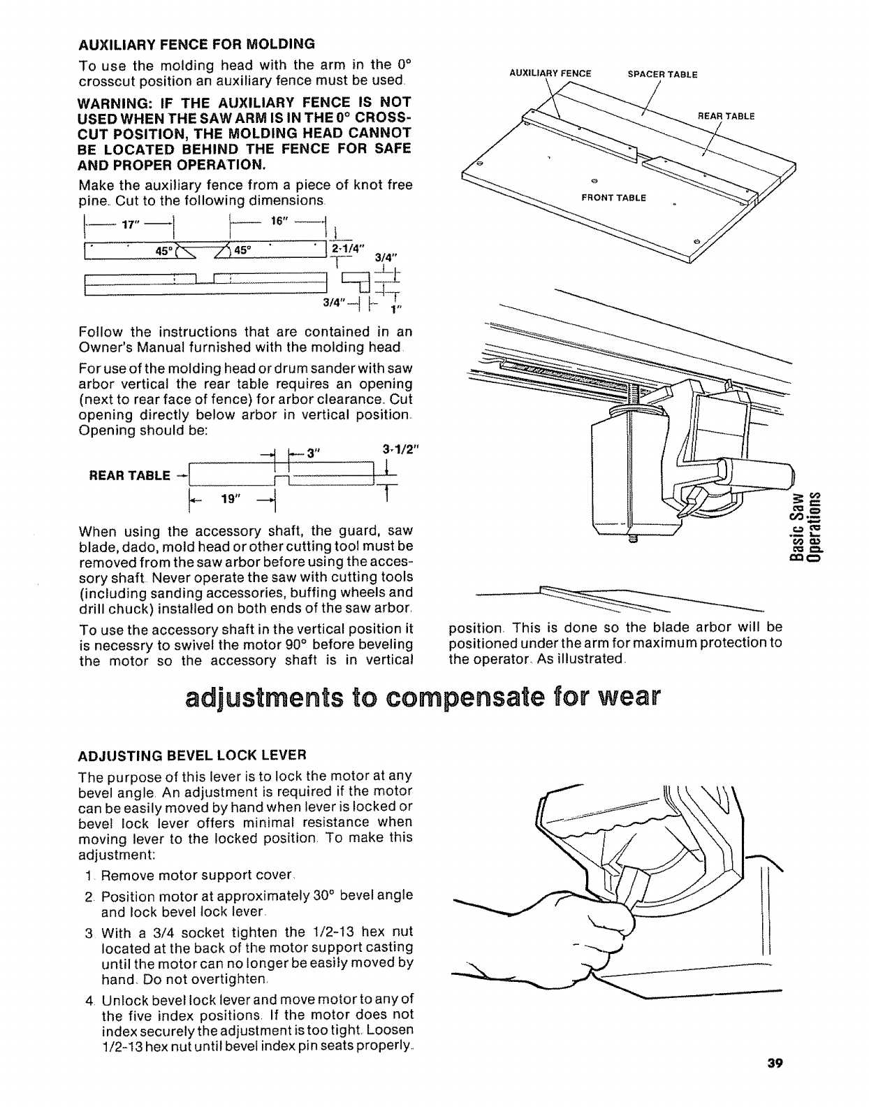
AUXILIARYFENCEFORMOLDING
To use the molding head with the arm in the 0°
crosscut position an auxiliary fence must be used
WARNING: IF THE AUXILIARY FENCE IS NOT
USED WHEN THE SAW ARM IS IN THE 0° CROSS-
CUT POSITION, THE MOLDING HEAD CANNOT
BE LOCATED BEHIND THE FENCE FOR SAFE
AND PROPER OPERATION.
Make the auxiliary fence from a piece of knot free
pine,. Cut to the following dimensions.
-t-- 3/4
3/4"--I I- 1"
Follow the instructions that are contained in an
Owner's Manual furnished with the molding head
For use of the molding head or drum sander with saw
arbor vertical the rear table requires an opening
(next to rear face of fence) for arbor clearance. Cut
opening directly below arbor in vertical position,
Opening should be:
3-1/2"
When using the accessory shaft, the guard, saw
blade, dado, mold head or other cutting tool must be
removed from the saw arbor before using the acces-
sory shaft Never operate the saw with cutting tools
(including sanding accessories, buffing wheels and
drill chuck) installed on both ends of the saw arbor,
To use the accessory shaft in the vertical position it
is necessry to swivel the motor 90° before beveling
the motor so the accessory shaft is in vertical
AUXILIARY FENCE SPACER TABLE
REAR TABLE
o
FRONT TABLE
position_ This is done so the blade arbor will be
positioned under the arm for maximum protection to
the operator_ As illustrated.
adjustments to compensate for wear
ADJUSTING BEVEL LOCK LEVER
The purpose of this lever is to lock the motor at any
bevel angle. An adjustment is required if the motor
can be easily moved by hand when lever is locked or
bevel lock lever offers minimal resistance when
moving lever to the locked position. To make this
adjustment:
1. Remove motor support cover
2. Position motor at approximately 30°bevel angle
and lock bevel lock lever.
3 With a 3/4 socket tighten the 1/2-13 hex nut
located at the back of the motor support casting
until the motor can no longer be easily moved by
hand. Do not overtighten,
4. Unlock bevel lock lever and move motor to any of
the five index positions. If the motor does not
index securely the adjustment is too tight. Loosen
1/2-13 hex nut until bevel index pin seats properly., 39
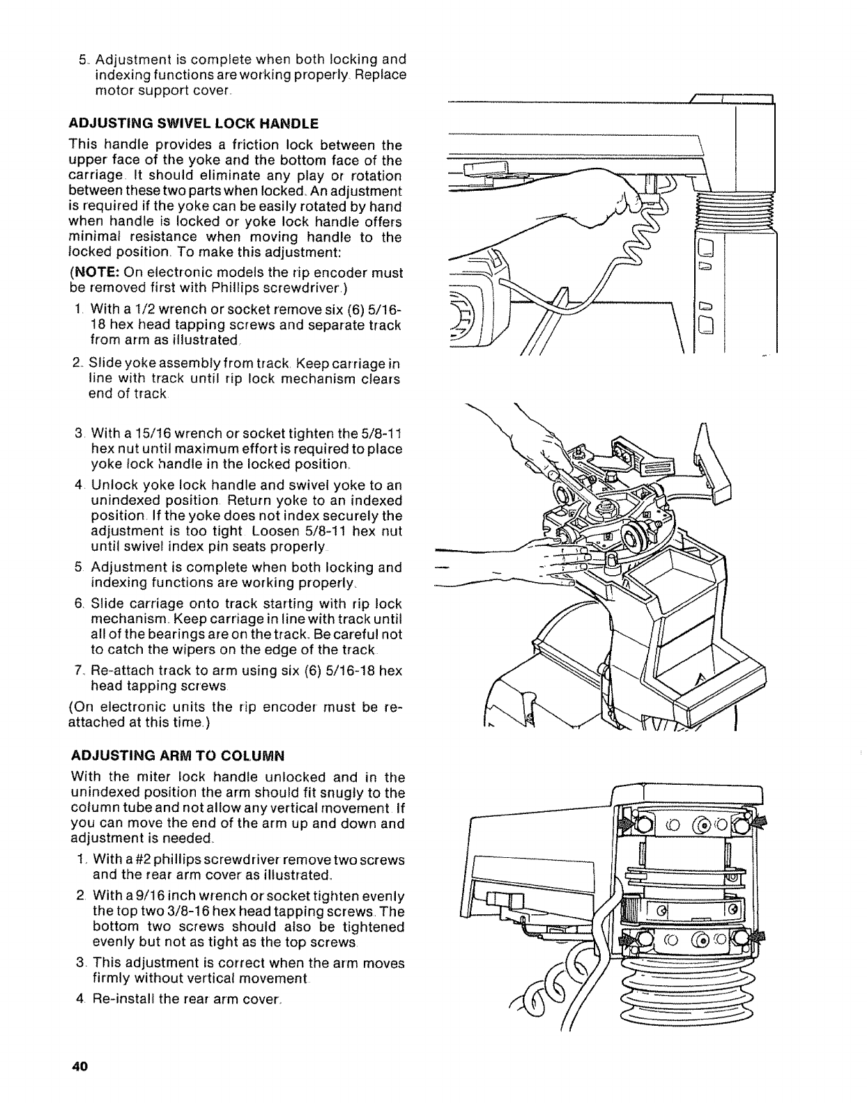
5,. Adjustment is complete when both locking and
indexing functions are working properly Replace
motor support cover..
ADJUSTING SWIVEL LOCK HANDLE
This handle provides a friction lock between the
upper face of the yoke and the bottom face of the
carriage, It should eliminate any play or rotation
between these two parts when locked, An adjustment
is required if the yoke can be easily rotated by hand
when handle is locked or yoke lock handle offers
minimal resistance when moving handle to the
locked position To make this adjustment:
(NOTE: On electronic models the rip encoder must
be removed first with Phillips screwdriver'.)
1. With a 1/2 wrench or socket remove six (6) 5/16-
18 hex head tapping screws and separate track
from arm as illustrated.
2,,Slide yoke assembly from track, Keep carriage in
line with track until rip lock mechanism clears
end of track
3. With a 15/16 wrench or socket tighten the 5/8-11
hex nut until maximum effort is required to place
yoke lock handle in the locked position,.
4. Unlock yoke lock handle and swivel yoke to an
unindexed position Return yoke to an indexed
position. If the yoke does not index securely the
adjustment is too tight Loosen 5/8-11 hex nut
until swivel index pin seats properly
5 Adjustment is complete when both locking and
indexing functions are working properly_
6 Slide carriage onto track starting with rip lock
mechanism.. Keep carriage in line with track until
all of the bearings are on the track,, Be careful not
to catch the wiper's on the edge of the track
7., Re-attach track to arm using six (6) 5/16-18 hex
head tapping screws
(On electronic units the rip encoder must be re-
attached at this time.)
ADJUSTING ARM TO COLUMN
With the miter lock handle unlocked and in the
unindexed position the arm should fit snugly to the
column tube and not allow any vertical movement If
you can move the end of the arm up and down and
adjustment is needed
1, With a #2 phillips screwdriver remove two screws
and the tear arm cover as illustrated,
2, With a 9/16 inch wrench or socket tighten evenly
the top two 3/8-16 hex head tapping screws. The
bottom two screws should also be tightened
evenJy but not as tight as the top screws,
3. This adjustment is correct when the arm moves
firmly without vertical movement
4, Re-insta!l the rear arm cover,.
40
\
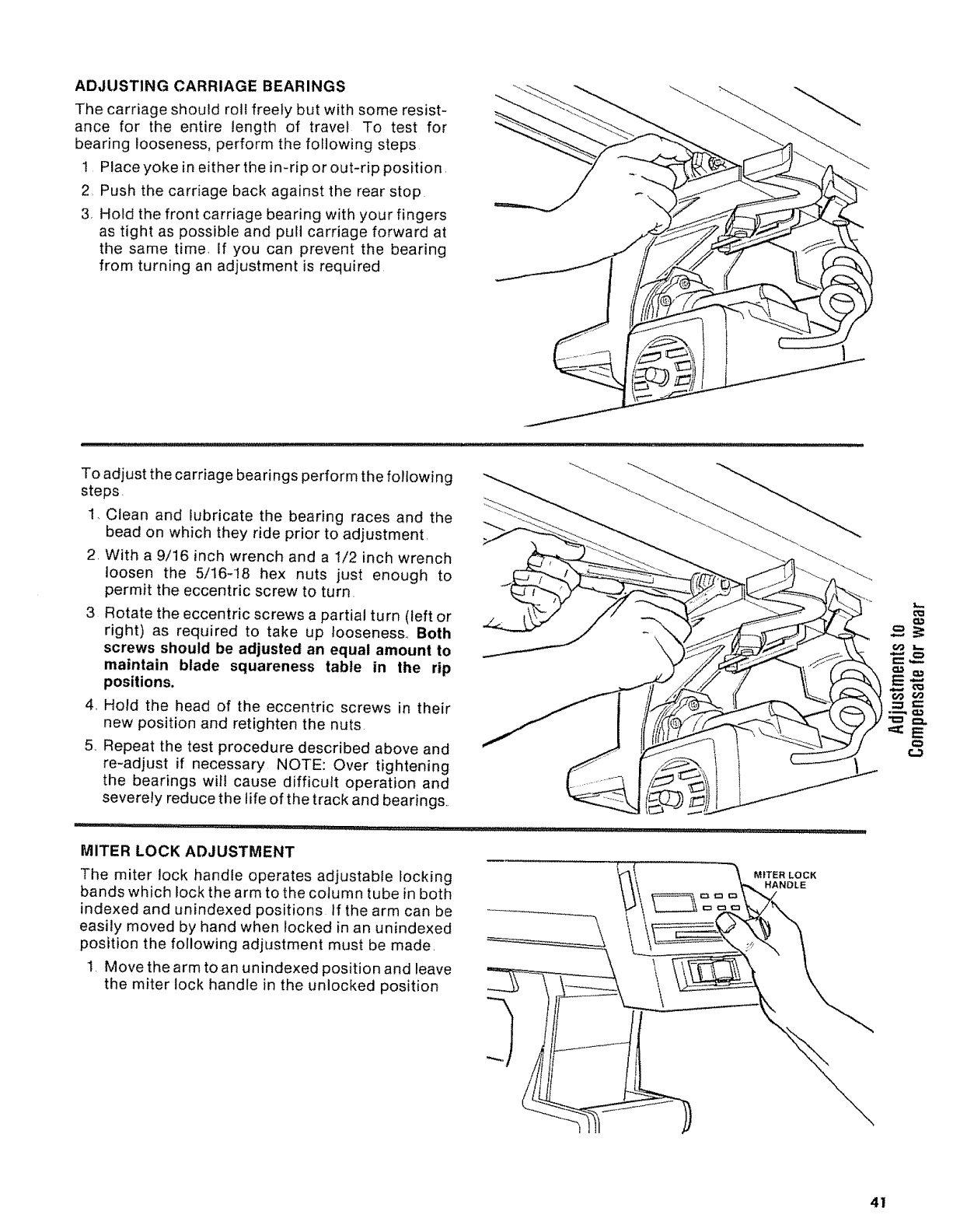
ADJUSTING CARRIAGE BEARINGS
The carriage should roll freely but with some resist-
ance for the entire length of travel To test for
bearing looseness, perform the following steps
1 Place yoke in either the in-rip or out-rip position.
2 Push the carriage back against the rear stop
3, Hold the front carriage bearing with your fingers
as tight as possible and pull carriage forward at
the same time, If you can prevent the bearing
from turning an adjustment is required
To adjust the carriage bearings perform the following
steps.
1, Clean and lubricate the bearing races and the
bead on which they ride prior to adjustment,
2, With a 9/16 inch wrench and a 1/2 inch wrench
loosen the 5/16-18 hex nuts just enough to
permit the eccentric screw to turn.
3 Rotate the eccentric screws a partial turn (left or
right) as required to take up looseness., Both
screws should be adjusted an equal amount to
maintain blade squareness table in the rip
positions.
4. Hold the head of the eccentric screws in their
new position and retighten the nuts
5,, Repeat the test procedure described above and
re-adjust if necessary NOTE: Over tightening
the bearings will cause difficult operation and
severely reduce the life of the track and bearings..
MITER LOCK ADJUSTMENT
The miter lock handle operates adjustable locking
bands which lock the arm to the column tube in both
indexed and unindexed positions. If the arm can be
easily moved by hand when locked in an unindexed
position the following adjustment must be made.
1 Move the arm to an unindexed position and leave
the miter lock handle in the unlocked position
MITER LOCK
HANDLE
€,O L_
60 r._
.=_,==
'==:E
¢#
41
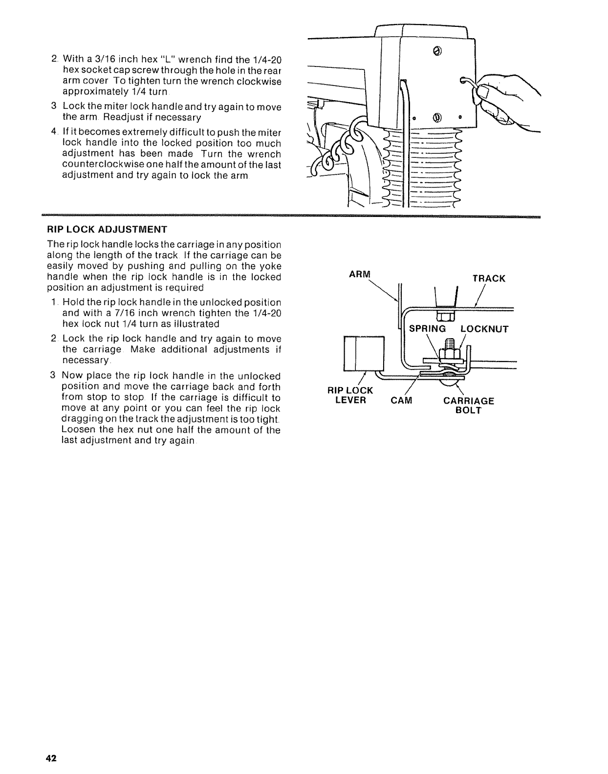
2, With a 3/16 inch hex "L" wrench find the 1/4-20
hex socket cap screwthrough the hole in the rear
arm cover To tighten turn the wrench clockwise
approximately 1/4 turn
3 Lock the miter lock handle and try again to move
the arm Readjust if necessary
4, If it becomes extremely difficult to push the miter
lock handle into the locked position too much
adjustment has been made Turn the wrench
counterclockwise one half the amount of the last
adjustment and try again to lock the arm
RIP LOCK ADJUSTMENT
The rip lock handle locks the carriage in any position
along the length of the track If the carriage can be
easily moved by pushing and pulling on the yoke
handle when the rip lock handle is in the locked
position an adjustment is required
1. Hold the rip lock handle in the unlocked position
and with a 7/t6 inch wrench tighten the 1/4-20
hex lock nut 1/4 turn as illustrated
2 Lock the rip lock handle and try again to move
the carriage Make additional adjustments if
necessary,
3 Now place the rip lock handle in the unlocked
position and move the carriage back and forth
from stop to stop If the carriage is difficult to
move at any point or you can feel the rip lock
dragging on the track the adjustment is too tight,
Loosen the hex nut one half the amount of the
last adjustment and try again
ARM TRACK
L_/
SPRING LOCKNUT
RIP LOCK _'_..... /" "'-_\'
LEVER CAM CARRIAGE
BOLT
42
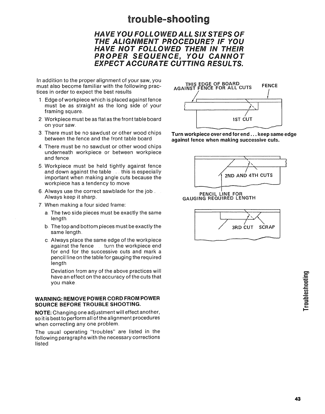
troubUe-shooting
HA VE YOU FOLLOWED ALL SIX STEPS OF
THE ALIGNMENT PROCEDURE? IF YOU
HAVE NOT FOLLOWED THEM IN THEIR
PROPER SEQUENCE, YOU CANNOT
EXPECT A CCURA TE CUTTING RESUL TS.
In addition to the proper alignment of your saw, you
must also become familiar with the following prac-
tices in order to expect the best results
1. Edge of workpiece which is placed against fence
must be as straight as the tong side of your
framing square..
2 Workpiece must be as flat as the front table board
on your saw..
3. There must be no sawdust or other wood chips
between the fence and the front table board
4. There must be no sawdust or other wood chips
underneath workpiece or between workpiece
and fence.
5. Workpiece must be held tightly against fence
and down against the table ... this is especially
important when making angle cuts because the
workpiece has a tendency to move
6. Always use the correct sawblade for the job ..
Always keep it sharp..
7 When making a four sided frame:
a. The two side pieces must be exactly the same
length,
b The top and bottom pieces must be exactly the
same length..
c. Always place the same edge of the workpiece
against the fence turn the workpiece end
for end for the successive cuts and mark a
pencil lineon the table for gauging the required
length
Deviation from any of the above practices will
have an effect on the accuracy of the cuts that
you make.
WARNING: REMOVE POWER CORD FROM POWER
SOURCE BEFORE TROUBLE SHOOTING°
NOTE: Changing one adjustment will effect another,
so it is best to perform all of the alignment procedures
when correcting any one problem.
The usual operating "troubles" are listed in the
following paragraphs with the necessary corrections
listed
THIS EDGE OF BOARD
AGAINST FENCE FOR ALL CUTS
• \
1ST CUT
FENCE
/
Turn workpiece over end/or end.., keep same edge
against fence when making successive cuts.
PENCIL LINE FOR
GAUGING REQUIRED LENGTH
l
60
..€=
i--
43
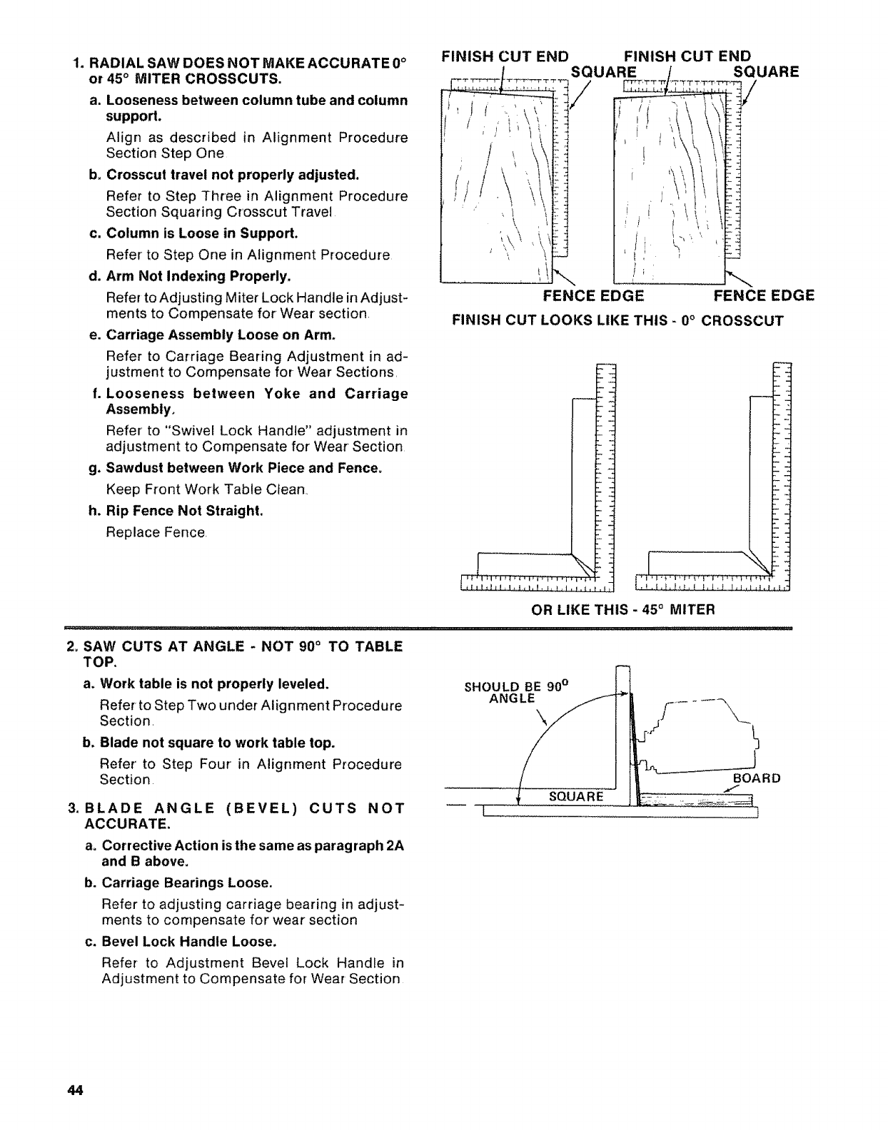
1. RADIAL SAW DOES NOT MAKE ACCURATE 0°
or 45 ° MITER CROSSCUTS.
a. Looseness between column tube and column
support,
Align as described in Alignment Procedure
Section Step One
b, Crosscut travel not properly adjusted.
Refer to Step Three in Alignment Procedure
Section Squaring Crosscut Travel
c, Column is Loose in Support.
Refer to Step One in Alignment Procedure
d. Arm Not Indexing Properly,
Refer to Adjusting Miter Lock Handle in Adjust-
ments to Compensate for Wear section.
e. Carriage Assembly Loose on Arm.
Refer to Carriage Bearing Adjustment in ad-
justment to Compensate for-Wear Sections,
f. Looseness between Yoke and Carriage
Assembly,
Refer to "Swivel Lock Handle" adjustment in
adjustment to Compensate for Wear Section
g, Sawdust between Work Piece and Fence,
Keep Front Work Table Clean•
h, Rip Fence Not Straight.
Replace Fence.
FINISH CUT END
J(
/
FINISH CUT END
\
SQUARE
/SQUARE
FENCEEDGE FENCEEDGE
FINISHCUTLOOKSLIKETHIS-0°CROSSCUT
OR LIKE THIS - 45° MITER
2, SAW CUTS AT ANGLE -NOT 900 TO TABLE
TOP,
a. Work table is not properly leveled.
Refer to Step Two under Alignment Procedure
Section
b. Blade not square to work table top.
Refer' to Step Four in Alignrnent Procedure
Section
3. BLADE ANGLE (BEVEL) CUTS NOT
ACCURATE.
a= Corrective Action is the same as paragraph 2A
and B above.
SHOULD BE 90 °
ANGLE
SQUARE
[
J
BOARD
b. Carriage Bearings Loose.
Refer to adjusting carriage bearing in adjust-
ments to compensate for wear section
c. Bevel Lock Handle Loose.
Refer to Adjustment Bevel Lock Handle in
Adjustment to Compensate for Wear Section
44
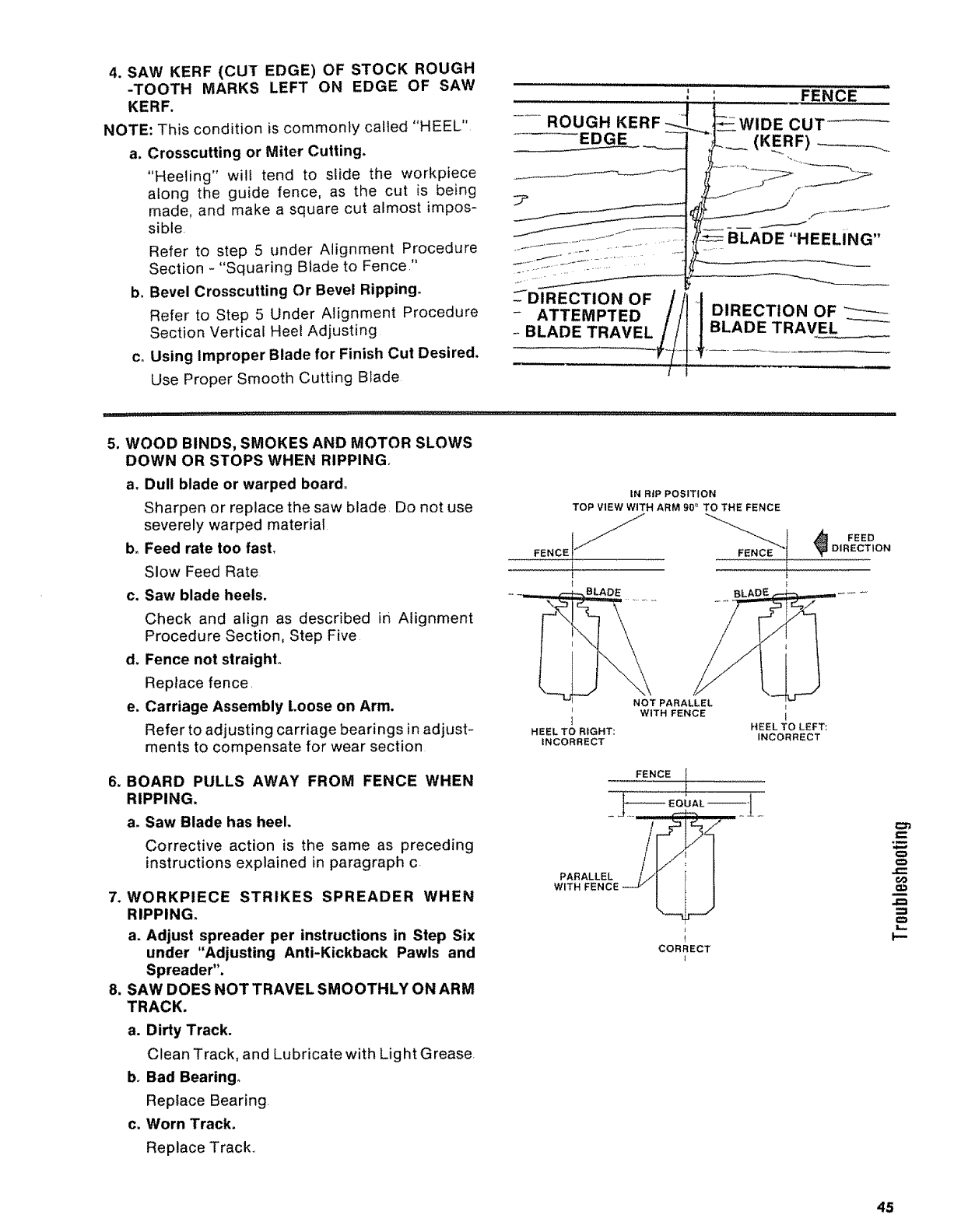
4. SAWKERF(CUTEDGE)OFSTOCKROUGH
-TOOTH MARKSLEFTON EDGE OF SAW
KERF,
NOTE:This condition is commonly called "HEEL"
a, Crosscutting or Miter Cutting,
"Heeling" will tend to slide the workpiece
along the guide fence, as the cut is being
made, and make a square cut almost impos-
sible.
Refer to step 5 under Alignment Procedure
Section -"Squaring Blade to Fence."
b. Bevel Crosscutting Or Bevel Ripping.
Refer to Step 5 Under Alignment Procedure
Section Vertical Heel Adjusting
c. Using Improper Blade for Finish Cut Desired.
Use Proper Smooth Cutting Blade
..... ROUGH KERF
EDGE
,j
...... BLADE "HEELING"
---DIRECTION OF/i1 !
- ATTEMPTED DIRECTION OF
-BLADE TRAVEL LADE TRAVEL
5. WOOD BINDS, SMOKES AND MOTOR SLOWS
DOWN OR STOPS WHEN RIPPING.
a. Dull blade or warped board°
Sharpen or replace the saw blade. Do not use
severely warped material
b_ Feed rate too fast,
Slow Feed Rate
c. Saw blade heels.
Check and align as described in Alignment
Procedure Section, Step Five
d, Fence not straighL
Replace fence.
e, Carriage Assembly Loose on Arm,
Refer to adjusting carriage bearings in adjust-
ments to compensate for wear section
6, BOARD PULLS AWAY FROM FENCE WHEN
RIPPING.
ao Saw Blade has heel,
Corrective action is the same as preceding
instructions explained in paragraph c,
7. WORKPIECE STRIKES SPREADER WHEN
RIPPING.
a. Adjust spreader per instructions in Step Six
under "Adjusting Anti-Kickback Pawls and
Spreader".
8. SAW DOES NOT TRAVEL SMOOTHLY ON ARM
TRACK,
a, Dirty Track.
Clean Track, and Lubricate with Light Grease.
b. Bad Bearing,
Replace Bearing.
c. Worn Track.
Replace Track..
IN RiP POSITION
TOP VIEW WITH ARM 90 =TO THE FENCE
E
BLADE
NOT PARALLEL
WITH FENCE
HEEL TO RIGHT'. HEEL TO LEFT:
INCORRECT INCORRECT
FEEDDIRECTION
FENCE I
PARALLEL
WITH FENCE
CORRECT
c::
_m
O
OO
QJ)
L_
p-
45

9. CLAMPING FORCE NOT SUFFICIENTAT
MITERANGLESOTHERTHAN45°,
ao Miter Lock Handle requires Adjustment.
Refer to Adjusting Miter Lock Handle in Adjust-
ments to Compensate for Wear Section
10. CLAMPING FORCE NOT SUFFICIENT AT
BEVEL ANGLES OTHER THAN 45°.
a, Bevel Lock Handle Requires adjusting.
Refer to Adjusting Bevel Lock Handle in Adjust-
ments to Compensate for Wear Section,
11. DEPTH OF CUT VARIES FROM ONE END OF
WORK PIECE TO THE OTHER.
a, Table Top not parallel with Arm,
Refer-to attaching and leveling table mounting
support channels in Step Two of the Alignment
Procedure Section.
12, BLADE TENDS TO ADVANCE THROUGH
LUMBER TOO FAST°
a, Dull Blade.
Replace or sharpen blade.
b, Not advancing Saw Blade properly.
Draw Saw Blade across lumber with a slow
and steady pull
46
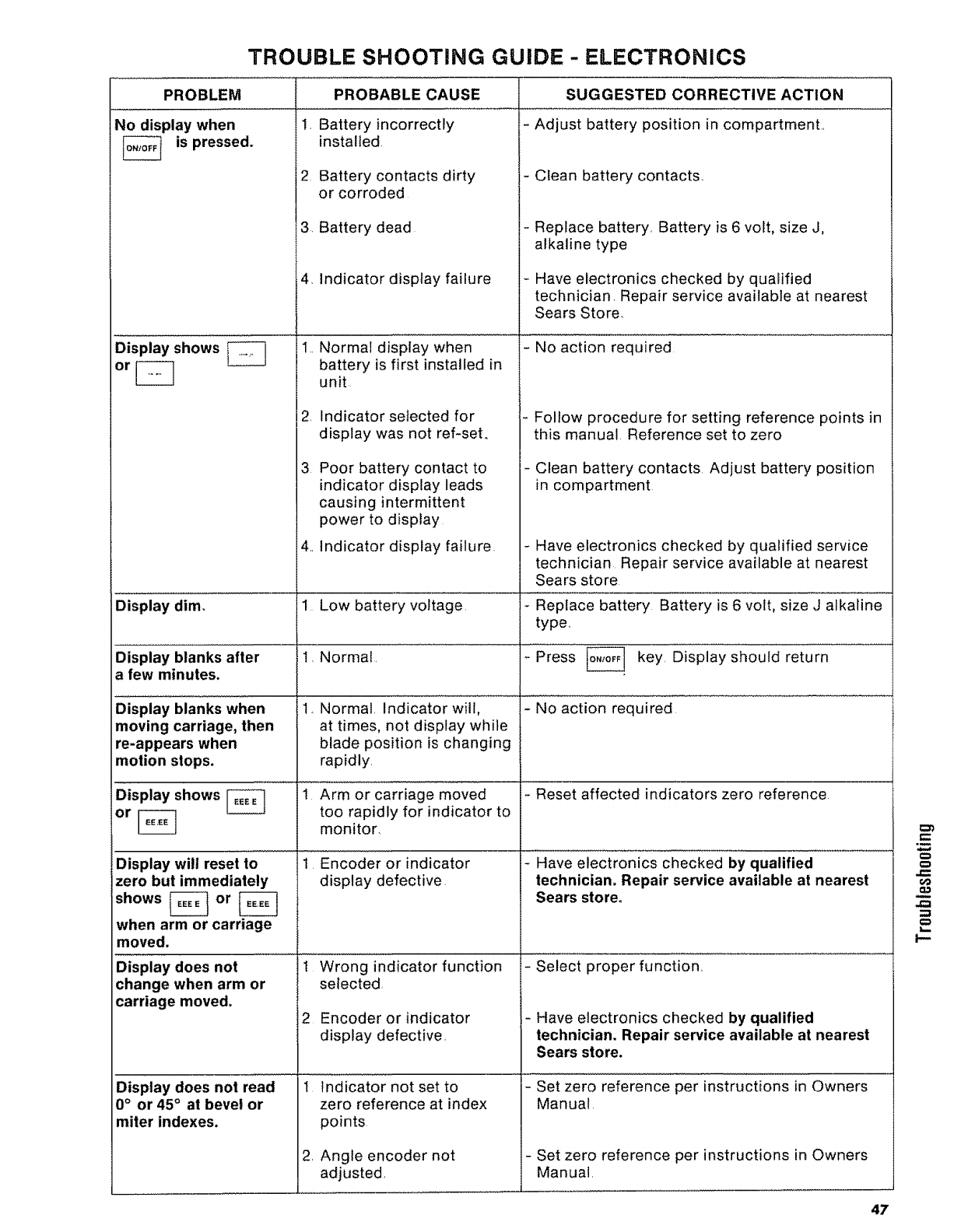
TROUBLE SHOOTING GUIDE -ELECTRONICS
PROBLEM
No display when
_is pressed.
Display shows
Display dim.
Display blanks after
a few minutes.
DisPlaY blanks When
moving carriage, then
re-appears when
motion stops.
PROBABLE CAUSE SUGGESTED CORRECTIVE ACTION
1, Battery incorrectly - Adjust battery position in compartment.
installed
2 Battery contacts dirty
or corroded
3. Battery dead
4, Indicator display failure
,,
,
-Clean battery contacts,
-Replace battery, Battery is 6 volt, size J,
alkaline type
- Have electronics checked by qualified
technician. Repair service available at nearest
Sears Store,
Normal display when - NO aCtiOn required
battery is first installed in
unit
Indicator selected for
display was not ref-set,
Poor battery contact to
indicator display leads
causing intermittent
power to display
4, Indicator display failure,
1Low battery voltage,
t, Normal,
- Follow procedure for setting reference points in
this manual Reference set to zero
- Clean battery contacts Adjust battery position
in compartment
- Have electronics checked by qualified service
technician Repair service available at nearest
Sears store
- Replace battery Battery is 6 volt, size J alkaline
type r,
Press _ key, Display should return
1, Normal, Indicator Willl -NO action required
at times, not display while
blade position is changing
rapidly,
Display shows _iArm 0r Carriage moved
too rapidly for indicator to
or _ monitor,
Display will reset to ii Enc0der or indicator
display defective
1 Wrong indicator function
selected
2 Encoder or indicator
display defective,
indicaior not set to
zero reference at index
points
zero but immediately
shows [_ or [_
when arm or carriage
moved,
Display does not
change when arm or
carriage moved,
Angle encoder not
adjusted,
Display does not read
0° or 45° at bevel or
miter indexes.
,
-Reset affected indicators zero reference
- Have electronics Checked by qualified .........
technician. Repair service available at nearest
Sears store,
- select proper function,
-Have electronics checked by qualified
technician. Repair service available at nearest
Sears store.
- Set zero reference per instructions in Owners
Manual
- Set zero reference per instructions in Owners
Manual
O
6¢
47
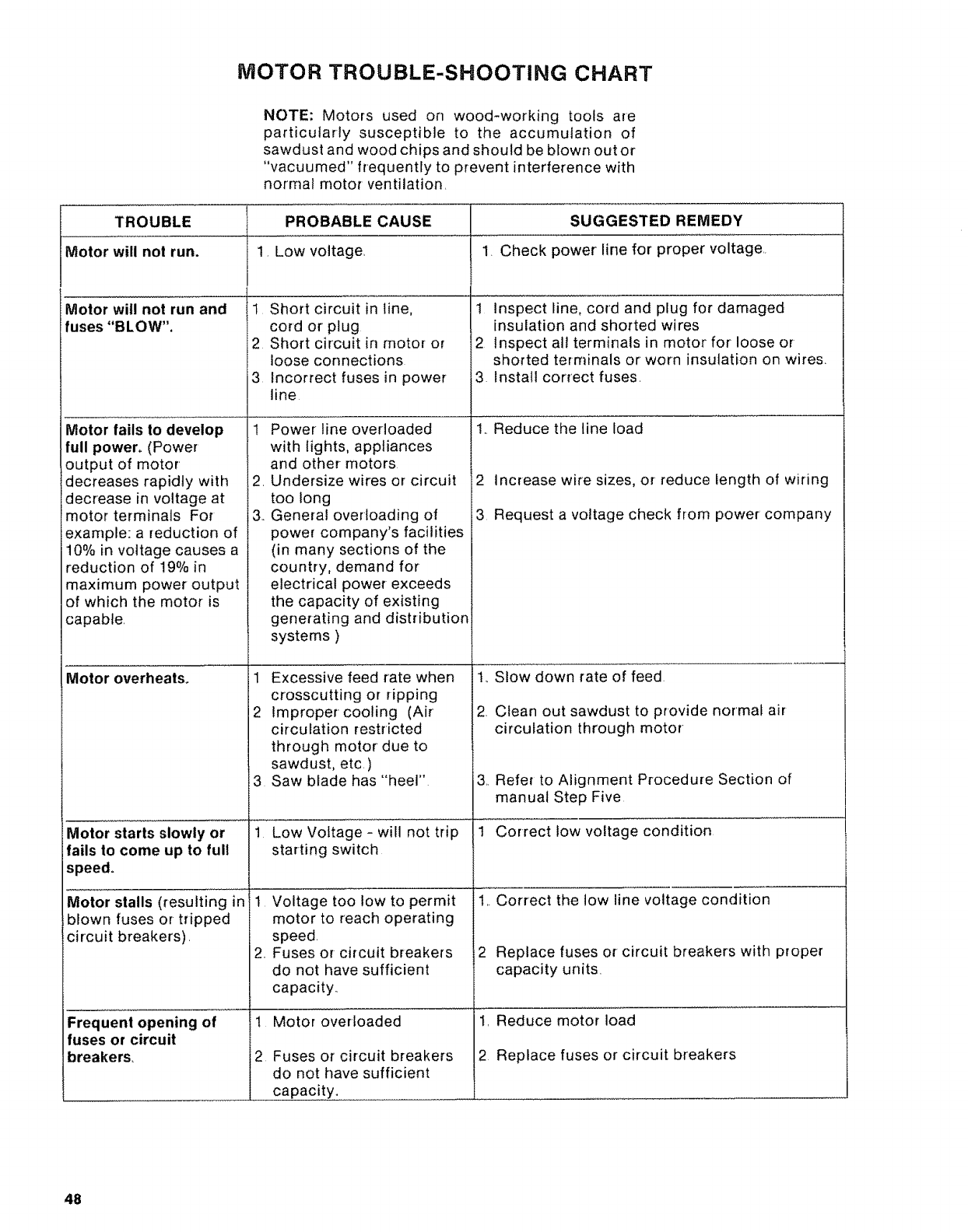
MOTOR TROUBLE-SHOOTING CHART
NOTE: Motors used on wood-working tools are
particularly susceptible to the accumulation of
sawdust and wood chips and should be blown out or
"vacuumed" frequently to prevent interference with
normal motor ventilation.
TROUBLE PROBABLE CAUSE SUGGESTED REMEDY
Motor will not run. !, Low voltage 1. Check power line for proper voltage
Motor will not run and
uses "BLOW".
Motor fails to develop
full power° (Power
output of motor
decreases rapidly with
decrease in voltage at
motor terminals For
example: a reduction of
10% in voltage causes a
reduction of 19% in
maximum power output
of which the motor is
capable.
Motor overheats.
Motor starts slowly or
fails to come up to full
speed.
Motor stalls (resulting in
blown fuses or tripped
circuit breakers).
Frequent opening of
fuses or circuit
breakers,
1 Short circuit in line,
cord or plug
2 Short circuit in motor or
loose connections
3 incorrect fuses in power
line
,
3..
Power line overloaded
with lights, appliances
and other- motors
Undersize wires or circuit
too long
General overloading of
power company's facilities
(in many sections of the
country, demand for
electrical power exceeds
the capacity of existing
generating and distribution
systems )
1 Excessive feed rate when
crosscutting or ripping
2 Improper cooling (Air
circulation restricted
through motor due to
sawdust, etc. )
3 Saw blade has "heel"
t Low Voltage- will not trip
starting switch
1 Voltage too low to permit
motor to reach operating
speed.
2.. Fuses or circuit breakers
do not have sufficient
capacity._
1 Motor overloaded
2Fuses or circuit breakers
do not have sufficient
capacity.
1 Inspect line, cord and plug for damaged
insulation and shorted wires
2 Inspect all terminals in motor for loose or
shorted terminals or worn insulation on wires.
3 install correct fuses.
1..Reduce the line load
2increase wire sizes, or reduce length of wiring
3 Request a voltage check from power company
1..Slow down rate of feed
2. Clean out sawdust to provide normal air
circulation through motor
3. Refer to Alignment Procedure Section of
manual Step Five
1 Correct low voltage condition
1..Correct the low line voltage condition
2 Replace fuses or circuit breakers with proper
capacity units.
1. Reduce motor load
2 Replace fuses or circuit breakers
48
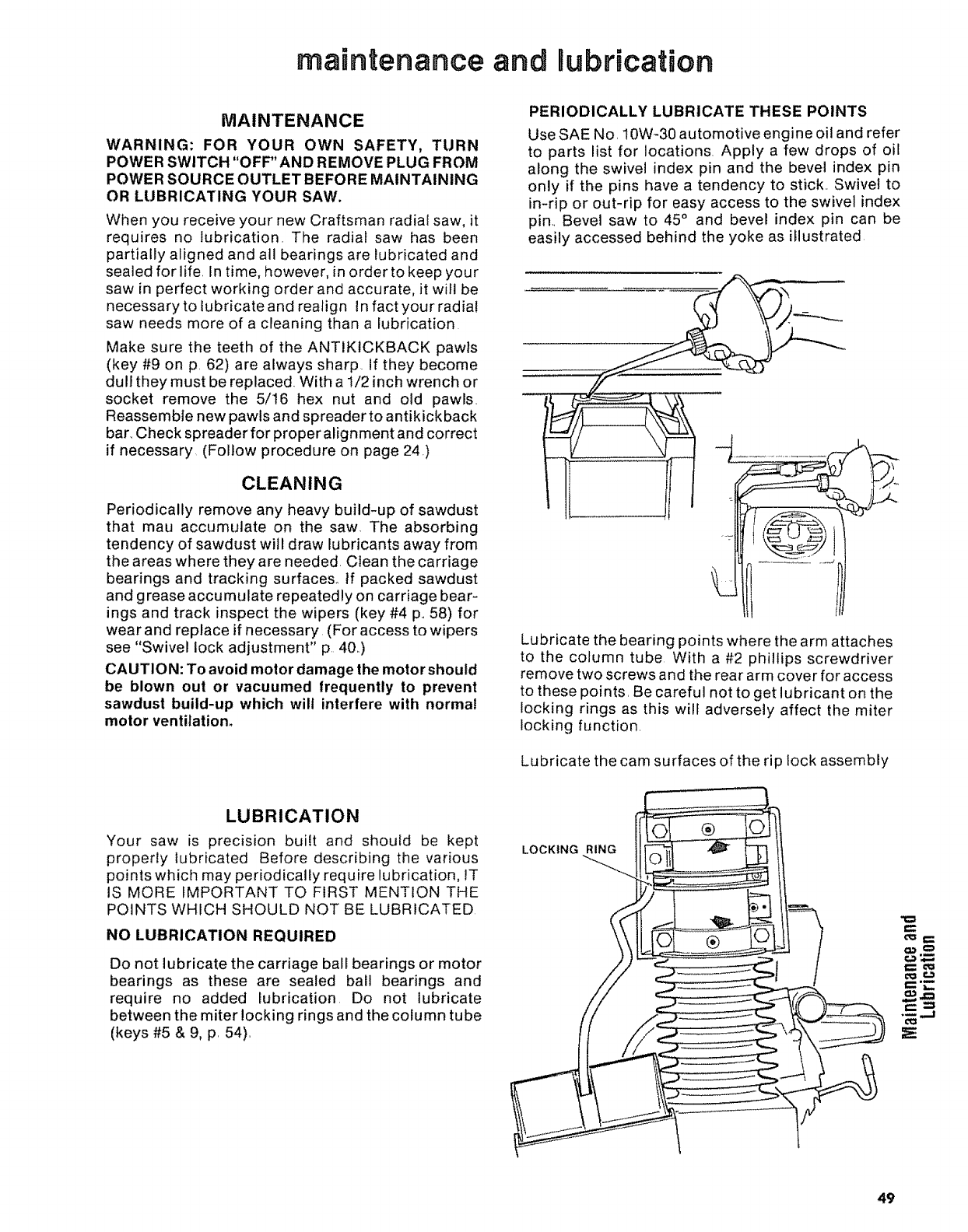
maintenance and Rubrication
MAINTENANCE
WARNING: FOR YOUR OWN SAFETY, TURN
POWER SWITCH "OFF" AND REMOVE PLUG FROM
POWER SOURCE OUTLET BEFORE MAINTAINING
OR LUBRICATING YOUR SAW.
When you receive your new Craftsman radial saw, it
requires no lubrication. The radial saw has been
partially aligned and all bearings are lubricated and
sealed for life. In time, however, in order to keep your
saw in perfect working order and accurate, it will be
necessary to lubricate and realign In fact your radial
saw needs more of a cleaning than a lubrication
Make sure the teeth of the ANTIKtCKBACK pawls
(key #9 on p. 62) are always sharp, if they become
dull they must be replaced. With a 1/2 inch wrench or
socket remove the 5/16 hex nut and old pawls.
Reassemble new pawls and spreader to antikickback
bar_Check spreader for proper alignment and correct
if necessary (Follow procedure on page 24)
CLEANING
Periodically remove any heavy build-up of sawdust
that mau accumulate on the saw. The absorbing
tendency of sawdust will draw lubricants away from
the areas where they are needed. Clean the carriage
bearings and tracking surfaces_ If packed sawdust
and grease accumulate repeatedly on carriage bear-
ings and track inspect the wipers (key #4 p,, 58) for
wear and replace if necessary. (For access to wipers
see "Swivel lock adjustment" p 40.)
CAUTION: To avoid motor damage the motor should
be blown out or vacuumed frequently to prevent
sawdust build-up which wilt interfere with normal
motor ventilatiom
PERIODICALLY LUBRICATE THESE POINTS
Use SAE No, 10W-30 automotive engine oil and refer
to parts list for locations. Apply a few drops of oil
along the swivel index pin and the bevel index pin
only if the pins have a tendency to stick.. Swivel to
in-rip or out-rip for easy access to the swivel index
pin., Bevel saw to 45° and bevel index pin can be
easily accessed behind the yoke as illustrated.
--q
Lubricate the bearing points where the arm attaches
to the column tube With a #2 phillips screwdriver
remove two screws and the rear arm cover for access
to these points, Be careful not to get lubricant on the
locking rings as this will adversely affect the miter
locking function.
Lubricate the cam surfaces of the rip lock assembly
LUBRICATION
Your saw is precision built and should be kept
properly lubricated Before describing the various
points which may periodically require lubrication, 1T
IS MORE fMPQRTANT TO FIRST MENTION THE
POINTS WHICH SHOULD NOT BE LUBRICATED
NO LUBRICATION REQUIRED
Do not lubricate the carriage ball bearings or motor
bearings as these are sealed ball bearings and
require no added lubrication Do not lubricate
between the miter locking rings and the column tube
(keys #5 & 9, p, 54),
LOCKING RING
o,,_0
49
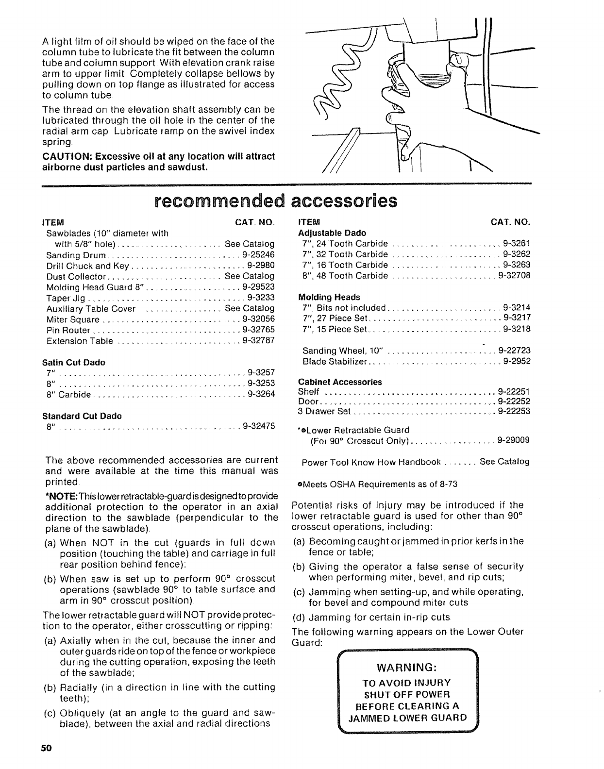
A light filmofoi! shouldbewipedonthefaceof the
columntubeto lubricatethefit betweenthecolumn
tubeandcolumnsupport.Withelevationcrankraise
armto upperlimit Completelycollapsebellowsby
pullingdownontopflangeasillustratedfor-access
to columntube.
Thethreadon theelevationshaftassemblycanbe
lubricatedthroughthe oil holein thecenterof the
radialarmcap Lubricaterampontheswivelindex
spring.
CAUTION:Excessive oil at any location will attract
airborne dust particles and sawdust.
recommended accessories
ITEM CAT,, NO,,
Sawblades (!0" diameter with
with 5/8" hole) ................................ See Catalog
Sanding Drum ...................................... 9-25246
Drill Chuck and Key ............................ 9-2980
Dust Collector ............................... See Catalog
Molding Head Guard 8"o ..................... 9-29523
Taper Jig ........................................ 9-3233
Auxiliary Table Cover ...................... See Catalog
Miter Square ...................................... 9-32056
Pin Router ........................................ 9-32765
Extension Table ................................... 9-32787
Satin Cut Dado
7". .............................................. 9-3257
8". .............................................. 9-3253
8" Carbide ................................... 9-3264
Standard Cut Dado
8". ........................................................ 9-32475
ITEM CAT,, NOr
Adjustable Dado
7", 24 Tooth Carbide .............................. 9-326t
7", 32 Tooth Carbide .......................... 9-3262
7", t6 Tooth Carbide ............................. 9-3263
8", 48 Tooth Carbide ............................. 9-32708
Molding Heads
7" Bits not included .......................... 9-3214
7", 27 Piece Set ................................... 9-3217
7", !5 Piece Set .............................. 9-3218
Sanding Wheel, !0" o............................. 9-22723
Blade Stabilizer ................................. 9-2952
Cabinet Accessories
Shelf .................................... 9-22251
Door. ..................................... 9-22252
3 Drawer Set ................................. 9-22253
'eLower Retractable Guard
(For 90°Crosscut Only) ..................... 9-29009
The above recommended accessories are current
and were available at the time this manual was
printed
*NOTE:This lower retractable-guard isdesigned to provide
additional protection to the operator in an axial
direction to the sawblade (perpendicular to the
plane of the sawblade),
(a) When NOT in the cut (guards in full down
position (touching the table) and carriage in fult
rear position behind fence):
(b) When saw is set up to perform 90 °crosscut
operations (sawblade 90° to table surface and
arm in 90°crosscut position),
The lower retractable guard wilt NOT provide protec-
tion to the operator, either crosscutting or ripping:
(a) Axially when in the cut, because the inner and
outer guards ride on top of the fence or workpiece
during the cutting operation, exposing the teeth
of the sawbtade;
(b) Radially (in a direction in line with the cutting
teeth);
(c) Obliquely (at an angle to the guard and saw-
blade), between the axial and radial directions
Power Tool Know How Handbook ......... See Catalog
eMeets OSHA Requirements as of 8-73
Potential risks of injury may be introduced if the
lower retractable guard is used for other- than 90 °
crosscut operations, including:
(a) Becoming caught or jammed in prior kerfs in the
fence or table;
(b) Giving the operator a false sense of security
when performing miter, bevel, and rip cuts;
(c) Jamming when setting-up, and while operating,
for bevel and compound miter cuts
(d) Jamming for certain in-rip cuts
The following warning appears on the Lower Outer
Guard:
WARNING:
TO AVOID INJURY
SHUT OFF POWER
BEFORE CLEARING A
,JAMMED LOWER GUARD
__....... ....... _....... _._
5O

NOTES
51
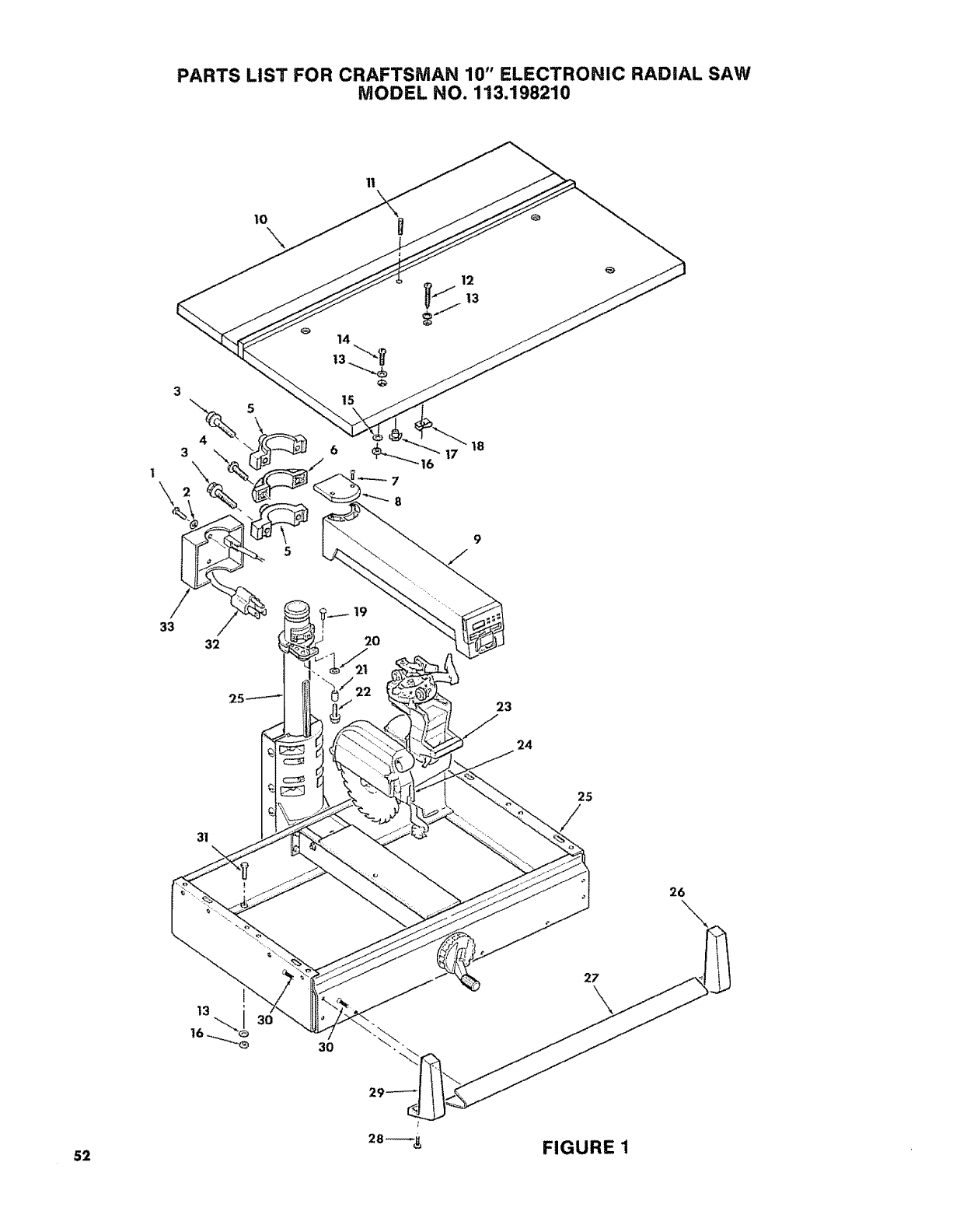
PARTS LIST FOR CRAFTSMAN 10" ELECTRONIC RADIAL SAW
MODEL NO. 113.198210
11
3
\
33
4
\
32
10\
14
15
6
7
12
23
24
25
31
52
3O
26
28--_ FIGURE 1
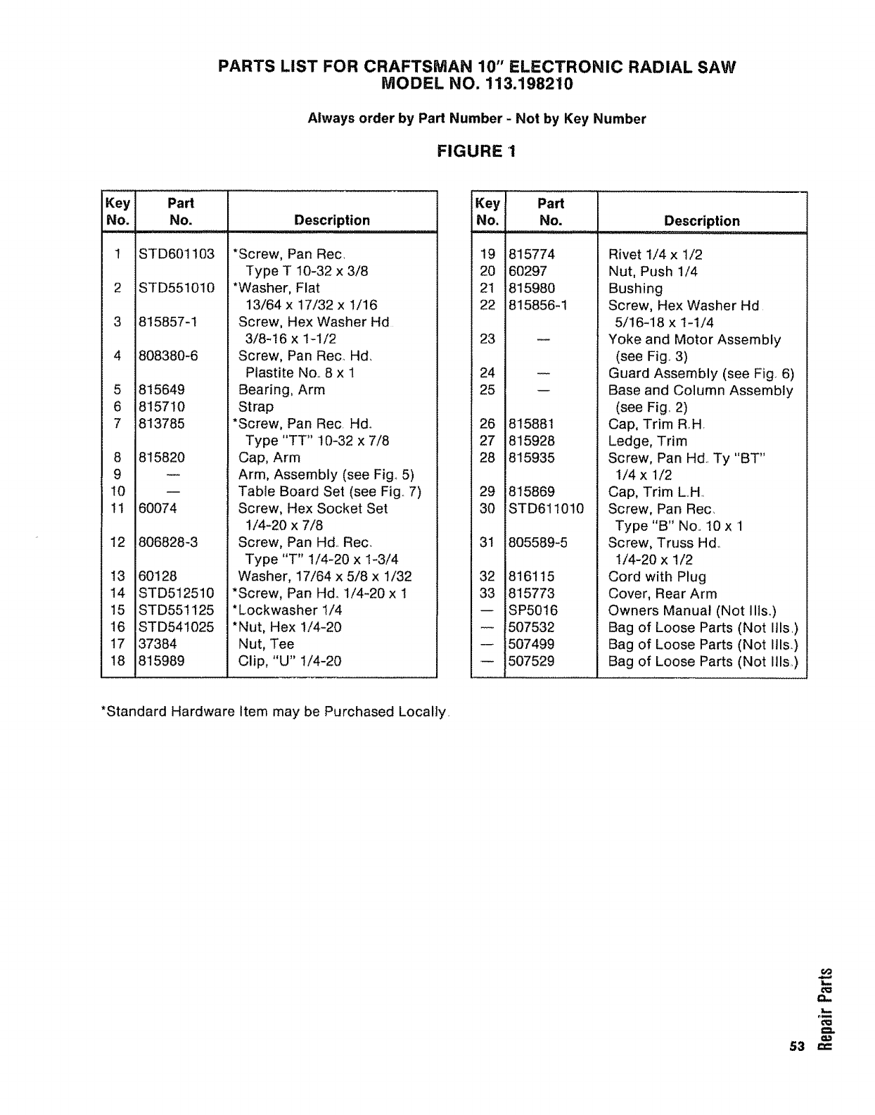
PARTS LIST FOR CRAFTSMAN 10" ELECTRONIC RADIAL SAW
MODEL NO. 113.198210
Always order by Part Number - Not by Key Number
FIGURE 1
Key Part
No. No.
iiill,,
I STD601103
2STD551010
3 815857-1
4808380-6
5 815649
6 815710
7 813785
8 815820
9
t0
11 60074
12 806828-3
13 60128
14 STD512510
15 STD551125
16 STD541025
17 37384
18 815989
Description
*Screw, Pan Rec.
Type T 10-32 x 3/8
*Washer, Flat
13/64 x 17/32 x 1/16
Screw, Hex Washer Hd
3/8-16 x 1-1/2
Screw, Pan Rec_ Hd_
Piastite No.. 8 x 1
Bearing, Arm
Strap
*Screw, Pan Rec Hd°
Type "TT" 10-32 x 7/8
Cap, Arm
Arm, Assembly (see Fig.. 5)
Table Board Set (see Fig.. 7)
Screw, Hex Socket Set
!/4-20 x 7/8
Screw, Pan Hd.. Rec.
Type "T" 1/4-20 x 1-3/4
Washer, 17/64 x 5/8 x 1/32
*Screw, Pan Hd_ 1/4-20 x 1
*Lockwasher 1/4
*Nut, Hex 1/4-20
Nut, Tee
Clip, "U" t/4-20
Key
No.
19
20
21
22
23
24
25
26
27
28
29
30
31
32
33
w
Part
No. Description
815774
60297
815980
815856-1
w
815881
815928
815935
815869
STD611010
805589-5
816115
815773
SP5016
507532
i507499
507529
Rivet 1/4 x 1/2
Nut, Push 1/4
Bushing
Screw, Hex Washer Hd
5/16-18 x 1-1/4
Yoke and Motor Assembly
(see Fig° 3)
Guard Assembly (see Fig. 6)
Base and Column Assembly
(see Fig.. 2)
Cap, Trim RH,
Ledge, Trim
Screw, Pan Hd.. Ty "BT"
1/4 x 1/2
Cap, Trim L.H.
Screw, Pan Rec.
Type "B" No.. 10 x rl
Screw, Truss Hd.
1/4-20 x 1/2
Cord with Plug
Cover, Rear Arm
Owners Manual (Not IiIso)
Bag of Loose Parts (Not Itls_)
Bag of Loose Parts (Not Ills.)
Bag of Loose Parts (Not ills,.)
*Standard Hardware Item may be Purchased Locally.
60
t,l
L--
53 "_
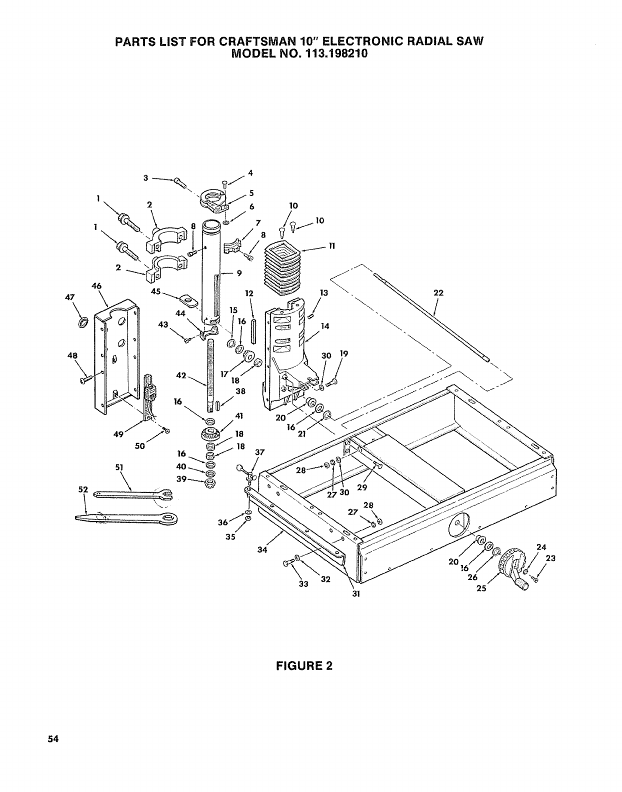
PARTS LIST FOR CRAFTSMAN 10" ELECTRONIC RADIAL SAW
MODEL NO. 113.198210
47
48
\
46
\
44
18
38
/
14
11
50
51
\
37
21
29
28
35
34
32
33 31
2O
26
25
24
23
/
FIGURE 2
54
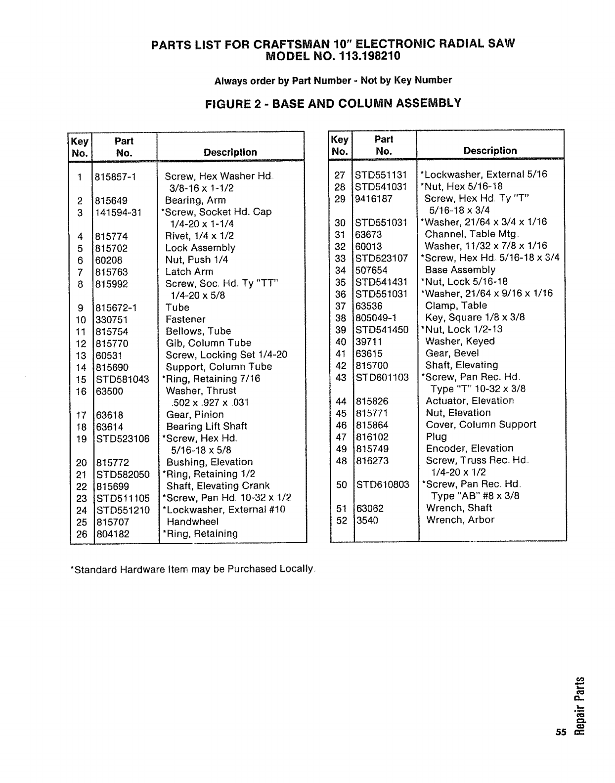
PARTS LIST FOR CRAFTSMAN 10" ELECTRONIC RADIAL SAW
MODEL NO. 113.198210
Always order by Part Number - Not by Key Number
FIGURE 2 - BASE AND COLUMN ASSEMBLY
Key I Part
No. l No.
_,_.... i=l'lll='H',
118'15857-1
2 1815649
3 1t41594-31
4 1815774
5 1815702
6 160208
'815763
81815992
9 1815672-1
10 1330751
11 1815754
12 1815770
13 160531
14 i 8t5690
15 STD581043
16 635OO
17 63618
18 63614
19 STD523106
20 815772
21 STD582050
22 815699
23 STD511105
24 STD551210
25 815707
26 804182
Description
i,i,,,
Screw, Hex Washer Hd,
3/8-16 x 1_1/2
Bearing, Arm
*Screw, Socket Hd. Cap
1/4-20 x 1-I/4
Rivet, 1/4 x 1/2
Lock Assembly
Nut, Push !/4
Latch Arm
Screw, Soc_ Hd.. Ty "TT"
1/4-20 x 5/8
Tube
Fastener
Bellows, Tube
Gib, Column Tube
Screw, Locking Set 1/4-20
Support, Column Tube
*Ring, Retaining 7/16
Washer, Thrust
.502 x °927 x .031
Gear, Pinion
Bearing Lift Shaft
*Screw, Hex Hal.
5/16-18 x 5/8
Bushing, Elevation
*Ring, Retaining I/2
Shaft, Elevating Crank
*Screw, Pan Hd 10-32 x 1/2
* Lockwasher, External #10
Handwheel
*Ring, Retaining
i(ey
No.
27
28
29
30
31
32
33
34
35
36
37
38
39
4O
41
42
43
44
45
46
47 J
49
48
5O
51
52
Part
No.
ii,i,,i,
ST D551131
STD541031
9416187
STD551031
63673
60013
STD523107
507654
STD541431
STD551031
63536
805049-1
STD541450
39711
63615
815700
STD601103
815826
815771
815864
816'102
815749
816273
STD610803
63062
3540
Description
*Lockwasher, External 5/16
*Nut, Hex 5/16-18
Screw, Hex Hd. Ty "T"
5/16-18 x 3/4
*Washer, 21/64 x 3/4 x 1/16
Channel, Table Mtg.
Washer, 11/32 x 7/8 x 1/16
*Screw, Hex Hd_ 5/16-18 x 3/4
Base Assembly
*Nut, Lock 5/16-18
*Washer, 21/64 x 9/16 x !/16
Clamp, Table
Key, Square 1/8 x 3/8
*Nut, Lock 1/2-13
Washer, Keyed
Gear, Bevel
Shaft, Elevating
*Screw, Pan Rec, Hd.
Type "T" 10-32 x 3/8
Actuator, Elevation
Nut, Elevation
Cover, Column Support
Plug
Encoder, Elevation
Screw, Truss Rec, Hd..
1/4-20 x 1/2
*Screw, Pan Reco Hd.
Type "AB" #8 x 3/8
Wrench, Shaft
Wrench, Arbor
*Standard Hardware Item may be Purchased Locally
I__
r-_
t==
55 ,',"
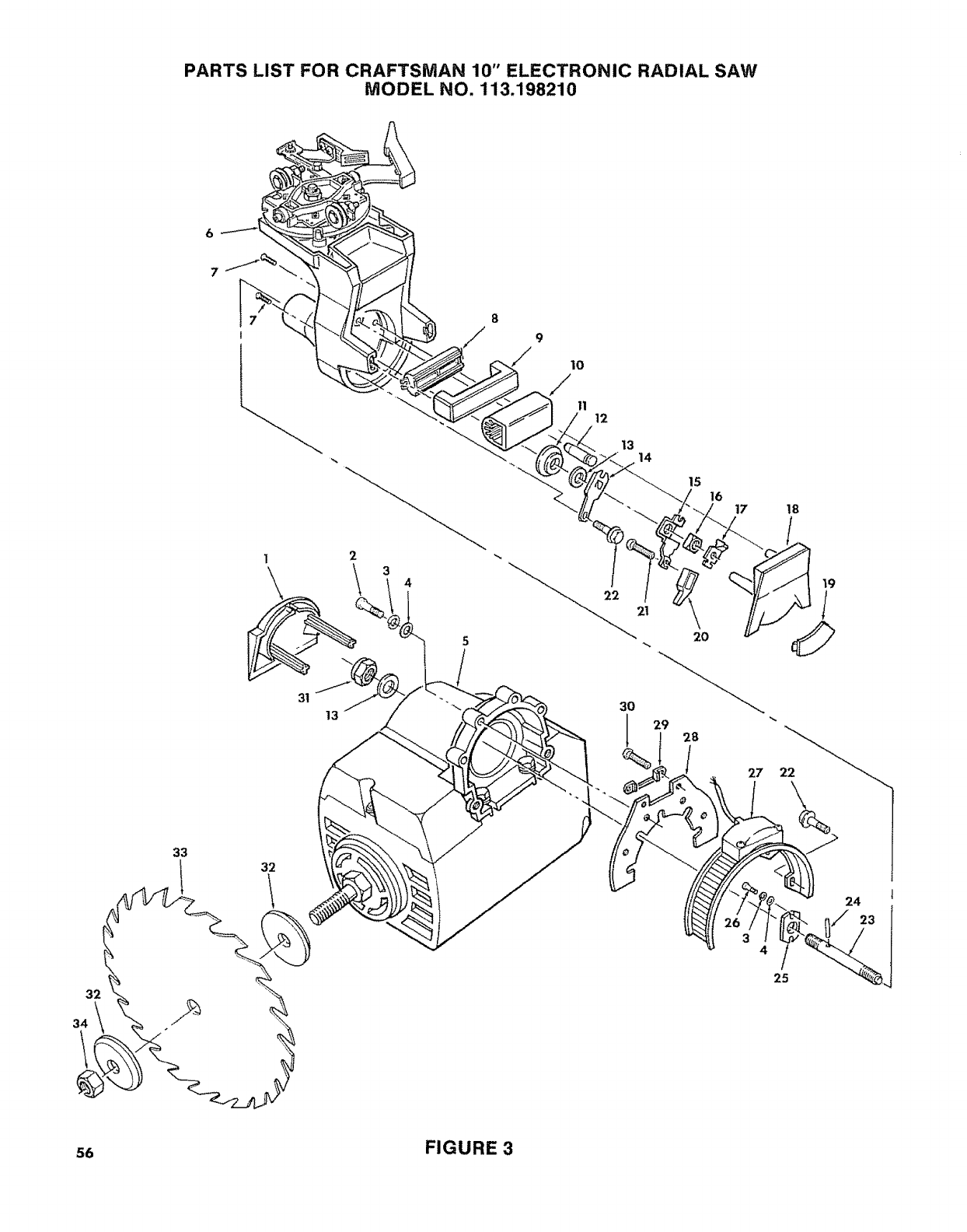
PARTS LIST FOR CRAFTSMAN 10" ELECTRONIC RADIAL SAW
MODEL NO. 113.198210
6
2
1
31
13
10
/
11 12
13
,14
15 16
2O
28
17
27
18
32
34
33 32
24
4
I
25
56 FIGURE 3
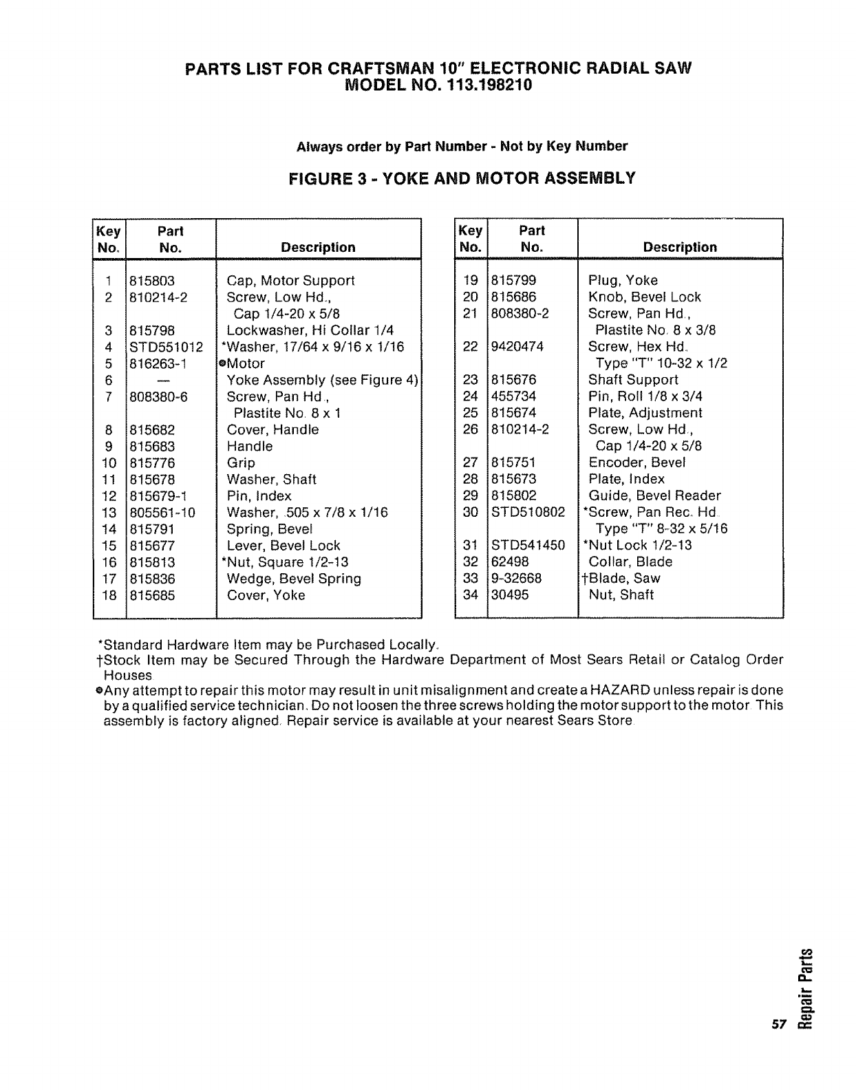
PARTS LIST FOR CRAFTSMAN 10" ELECTRONIC RADIAL SAW
MODEL NO. 113.198210
Always order by Part Number -Not by Key Number
FIGURE 3 - YOKE AND MOTOR ASSEMBLY
KeY I Part
I I No.
1 815803
2 810214-2
3 (815798
4 ISTD55!0!2
5 1816263-1
71808380-6
8 (815682
9 1815683
10 1815776
11 1815678
12 1815679-1
13 (805561-10
14 1815791
15 1815677
16 1815813
117 1815836
815685
............. Description ..
Cap, Motor Support
Screw, Low Hd.,,
Cap 1/4-20 x 5/8
.Lockwasher, Hi Collar 1/4
Washer, 17/64 x 9/16 x 1/16
oMotor
Yoke Assembly (see Figure 4)
Screw, Pan Hd,,
Plastite No. 8 x 1
Cover, Handle
Handle
Grip
Washer, Shaft
Pin, Index
Washer, 505 x 7/8 x 1/16
Spring, Bevel
Lever, Bevel Lock
*Nut, Square t/2-13
Wedge, Bevel Spring
Cover, Yoke
Key Part
No. No. Description
19 815799
20 815686
21 808380-2
22 9420474
23 815676
24 455734
25 815674
26 810214-2
27 815751
28 815673
29 815802
30 STD510802
3t STD541450
32 62498
33 9-32668
34 30495
Plug, Yoke
Knob, Bevel Lock
Screw, Pan Hd,,
Plastite No, 8 x 3/8
Screw, Hex Hd.,
Type "T" 10-32 x 1/2
Shaft Support
Pin, Roll 1/8 x 3/4
Plate, Adjustment
Screw, Low Hal,,
Cap 1/4-20 x 5/8
Encoder, Bevel
Plate, Index
Guide, Bevel Reader
*Screw, Pan Reco Hd
Type "T" 8-32 x 5/16
*Nut Lock 1/2-!3
Collar, Blade
tBtade, Saw
Nut, Shaft
*Standard Hardware Item may be Purchased Locally,,
1"Stock Item may be Secured Through the Hardware Department of Most Sears Retail or Catalog Order
Houses
eAny attempt to repair this motor may result in unit misalignment and create a HAZARD unless repair is done
by a qualified service technician. Do not loosen the three screws holding the motor support to the motor This
assembly is factory aligned, Repair service is available at your nearest Sears Store
mm
e=
57 ,',-
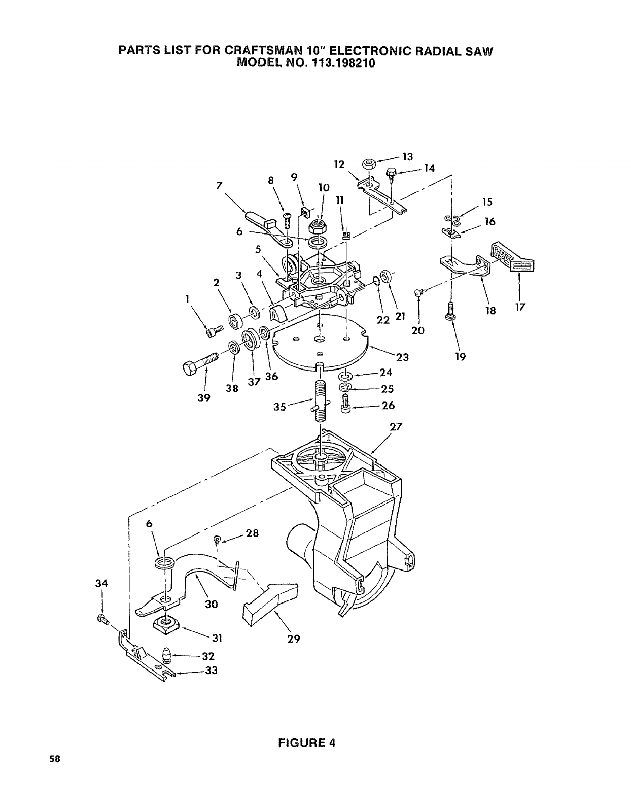
PARTS LIST FOR CRAFTSMAN 10" ELECTRONIC RADIAL SAW
MODEL NO. 113.198210
6
8 9
\ ,o
27
15
16
19
S8
FIGURE 4
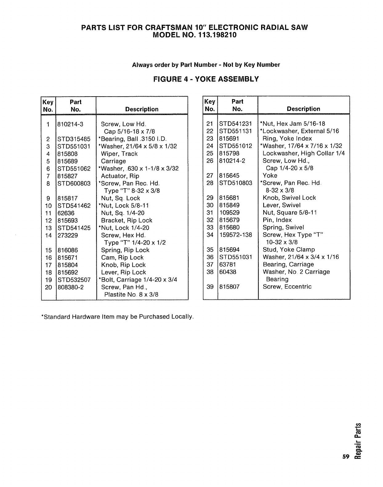
PARTS LIST FOR CRAFTSMAN 10" ELECTRONIC RADIAL SAW
MODEL NO. 113.198210
Always order by Part Number - Not by Key Number
FIGURE 4 - YOKE ASSEMBLY
Key Part
No. No, Description
Hi,i,
I 810214-3
2
3
4
5
6
7
8
STD315485
STD551031
815808
815689
STD551062
815827
STD600803
9 815817
10 STD541462
11 62636
12 815693
t3 STD541425
14 273229
15 816086
16 815671
17 815804
18 815692
19 STD532507
20 808380-2
Screw, Low Hd..
Cap 5/16-18 x 7/8
*Bearing, Ball ..3150 IoD..
*Washer, 21/64 x 5/8 x 1/32
Wiper, Track
Carriage
*Washer, .630 x 1-1/8 x 3/32
Actuator, Rip
*Screw, Pan Rec.. Hal..
Type "T" 8-32 x 3/8
Nut, Sq. Lock
*Nut, Lock 5/8-11
Nut, Sq. 1/4-20
Bracket, Rip Lock
*Nut, Lock 1/4-20
Screw, Hex Hd..
Type "T" !/4-20 x 1/2
Spring, Rip Lock
Cam, Rip Lock
Knob, Rip Lock
Lever, Rip Lock
*Bolt, Carriage 1/4-20 x 3/4
Screw, Pan Hd.,
Plastite No. 8 x 3/8
Key Part
No. No. Description
21
22
23
24
25
26
27
28
29
3O
31
32
33
34
35
36
37
38
39
iSTD541231
STD551131
815691
STD551012
815798
810214-2
815645
STD5t0803
815681
815849
109529
815679
815680
159572-138
815694
STD551031
63781
60438
815807
*Nut, Hex Jam 5/16-18
*Lockwasher, External 5/16
Ring, Yoke Index
*Washer, 17/64 x 7/16 x 1/32
Lockwasher, High Collar 1/4
Screw, Low Hd..,
Cap 1/4-20 x 5/8
Yoke
*Screw, Pan Rec.. Hd.
8-32 x 3/8
Knob, Swivel Lock
Lever, Swivel
Nut, Square 5/8-11
Pin, Index
Spring, Swivel
Screw, Hex Type "T"
10-32 x 3/8
Stud, Yoke Clamp
Washer, 21/64 x 3/4 x 1/16
Bearing, Carriage
Washer, No 2 Carriage
Bearing
Screw, Eccentric
*Standard Hardware Item may be Purchased Locally..
60
t==
_O
_m
O=l
59 ===
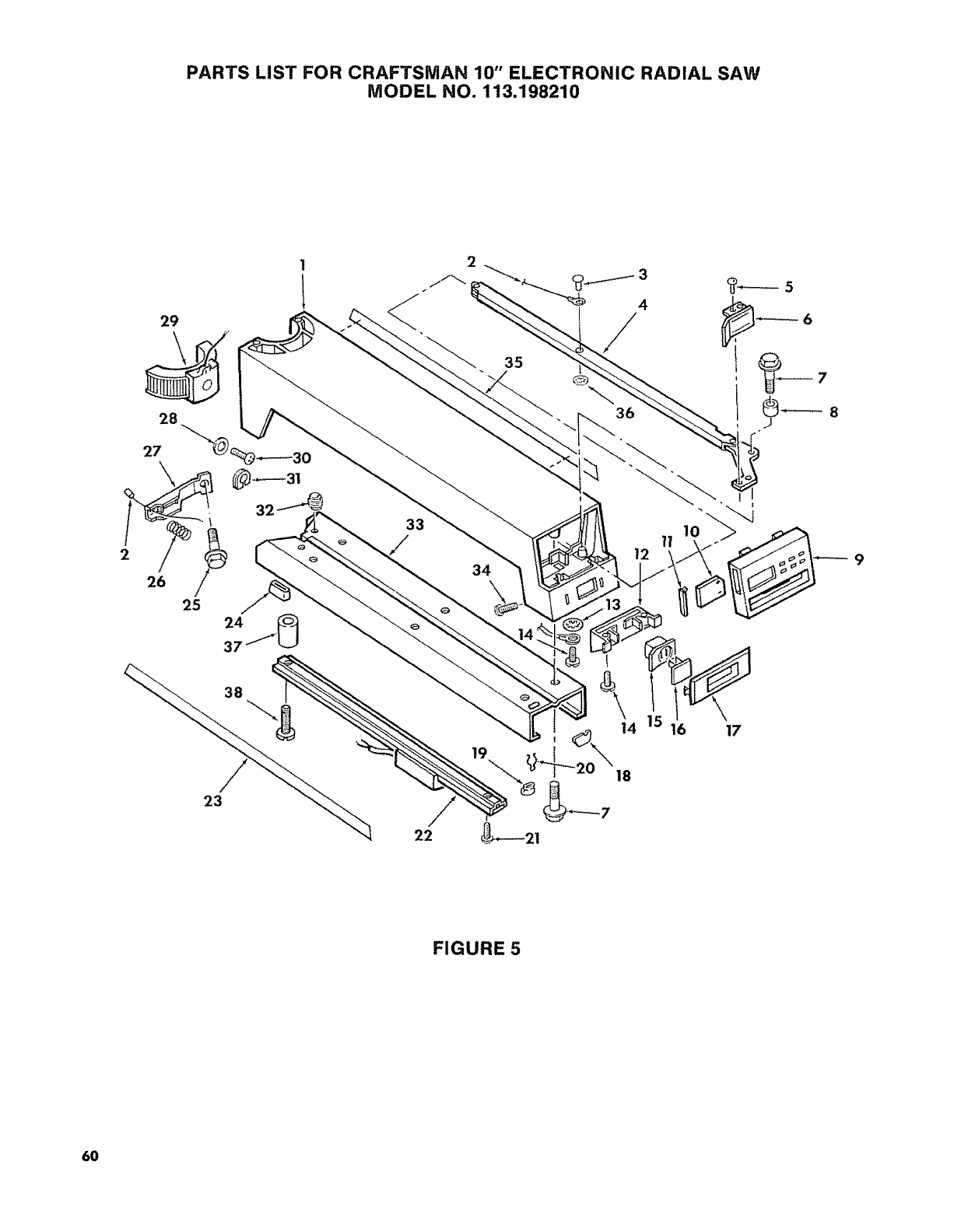
PARTS LIST FOR CRAFTSMAN 10" ELECTRONIC RADIAL SAW
MODEL NO. 113.198210
25 24
37
38
23
2
22
35
3
4
/
36
14
19
18
FIGURE 5
6O
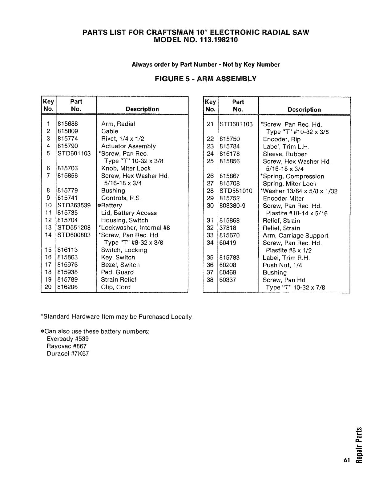
PARTS LIST FOR CRAFTSMAN 10" ELECTRONIC RADIAL SAW
MODEL NO. 113.198210
Always order by Part Number - Not by Key Number
FIGURE 5 -ARM ASSEMBLY
Key Part Key
No. No. Description No.
1815688 21
2 815809
3 815774 22
4 815790 23
5 STD60! 103 24
25
6 815703
7 815856 26
27
8 815779 28
9 815741 29
10 STD363539 30
11 815735
12 815704 31
t3 STD551208 32
14 STD600803 33
34
15 816113
16 815863 35
17 815976 36
18 815938 37
19 815789 38
20 816206
Arm, Radial
Cable
Rivet, 1/4 x 1/2
Actuator Assembly
*Screw, Pan Rec
Type "T" 10-32 x 3/8
Knob, Miter Lock
Screw, Hex Washer Hd
5/16-18 x 3/4
Bushing
Controls, RS
oBattery
Lid, Battery Access
Housing, Switch
*Lockwasher, internal #8
*Screw, Pan Rec, Hd,
Type "T" #8-32 x 3/8
Switch, Locking
Key, Switch
Bezel, Switch
Pad, Guard
Strain Relief
Clip, Cord
Part
No_ Description
STD601103
815750
815784
816178
815856
815867
815708
STD551010
815752
808380-9
815868
37818
815670
60419
815783
60208
60468
60337
*Screw, Pan Rec, Hd,
Type "T" #10-32 x 3/8
Encoder, Rip
Label, Trim L,,H,,
Sleeve, Rubber
Screw, Hex Washer Hd
5/16-18 x 3/4
*Spring, Compression
Spring, Miter Lock
*Washer 13/64 x 5/8 x 1/32
Encoder Miter
Screw, Pan Rec Hal,
Plastite #10-14 x 5/16
Relief, Strain
Relief, Strain
Arm, Carriage Support
Screw, Pan Rec,, Hd,
Plastite #8 x 1/2
Label, Trim R,,H,
Push Nut, 1/4
Bushing
Screw, Pan Hd
Type "T" 10-32 x 7/8
*Standard Hardware Item may be Purchased Locally.
eCan also usethese battery numbers:
Eveready #539
Rayovac #867
Duracel#TK67
_L
61 ,-,-
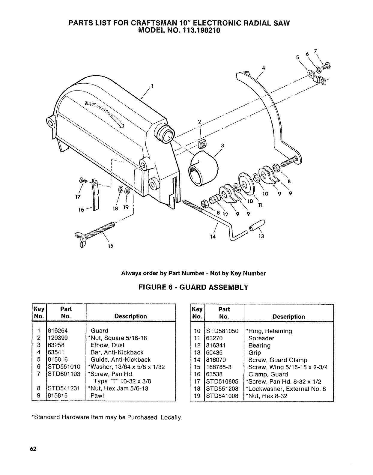
PARTS LIST FOR CRAFTSMAN 10" ELECTRONIC RADIAL SAW
MODEL NO. 113.198210
7
5
, \
8
9
Always order by Part Number - Not by Key Number
FIGURE 6 -GUARD ASSEMBLY
iNo.
i
2
34
5
6
7
8
9
..... J
Part
No.
816264
120399
63258
63541
815816
STD551010
ST D6011 O3
J
iSTD541231
,815815
Description
Guard
*Nut, Square 5/16-18
Elbow, Dust
Bar, Anti-Kickback
Guide, Anti-Kickback
*Washer, 13/64 x 5/8 x 1/32
*Screw, Pan Hd,
Type "T" 10-32 x 3/8
*Nut, Hex Jam 5/6-18
Pawl
Key
No.
10
11
12
13
14
15
16
17
18
19
Part
No,
;11 IUI
STD581050
63270
816341
60435
816070
166785-3
63538
STD510805
STD551208
STD541008
Description
,,,,,,,,,,,,,,,,,,,,,,,, ,,,, ,, ,,,, ,, ,,,,,,, ,
*Ring, Retaining
Spreader
Bearing
Grip
Screw, Guard Clamp
Screw, Wing 5/16-18 x 2-3/4
Clamp, Guard
*Screw, Pan Hd. 8-32 x 1/2
*Lockwasher, External No 8
*Nut, Hex 8-32
*Standard Hardware Item may be Purchased Locally,
62
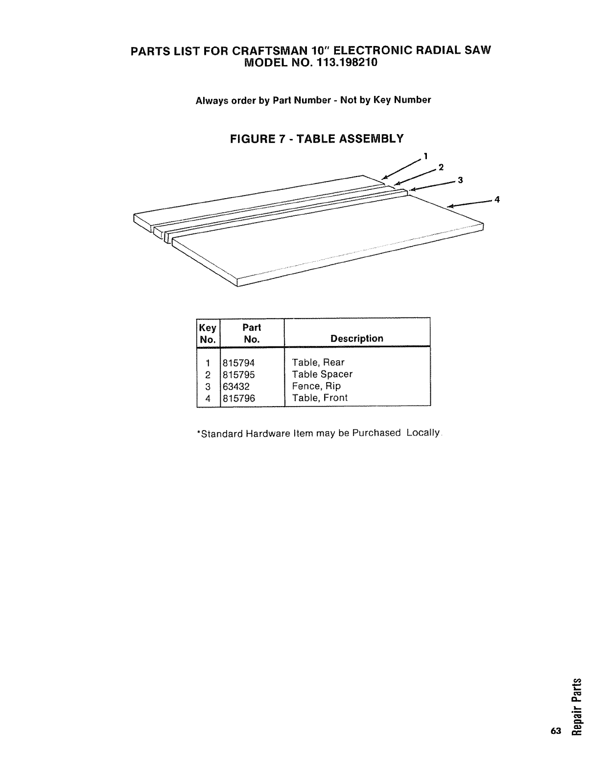
PARTS LIST FOR CRAFTSMAN 10" ELECTRONIC RADIAL SAW
MODEL NO. 113.1982'10
Always order by Part Number - Not by Key Number
FIGURE 7 - TABLE ASSEMBLY
Key
No,
1 8t5794
2 815795
3 63432
4 815796
Part
No. Description
........ ii,
Table, Rear
Table Spacer
Fence, Rip
Table, Front
*Standard Hardware Item may be Purchased Locally,
€_o
Ol=
.m
o_
63 ,-,-
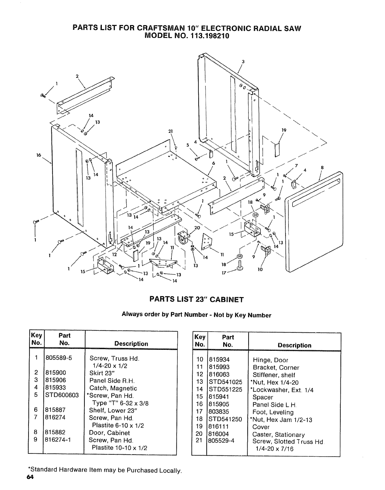
PARTS LiST FOR CRAFTSMAN 10" ELECTRONIC RADIAL SAW
MODEL NO. 113.198210
16
4
5
14
PARTS LIST 23" CABINET
Always order by Part Number -Not by Key Number
Key
No°
1
2
3
4
5
6
_8
!9
Part
No.
805589_5
815900
815906
815933
STD600603
815887
816274
815882
816274-1
Description
............. i,ll ,,
Screw, Truss Hd,,
1/4-20 x 1/2
Skirt 23"
Panel Side RH,.
Catch, Magnetic
*Screw, Pan Hd,,
Type "T" 6-32 x 3/8
Shelf, Lower 23"
Screw, Pan Hd
Plastite 6-10 x 1/2
Door, Cabinet
Screw, Pan Hdo
Plastite 10-10 x 1/2
Key
No.
10
11
12
13
14
15
16
17
18
19
20
21
Part
No,
815934
815993
816063
STD541025
STD551225
815941
815905
803835
_STD541250
,816111
1816004
i805529-4
Description
Hinge, Door
Bracket, Corner'
Stiffener, shelf
*Nut, Hex 1/4-20
*Lockwasher, Ex[ 1/4
Spacer
Panel Side LH
Foot, Leveling
*Nut, Hex Jam 1/2-13
Cover
Caster, Stationary
Screw, Slotted "[russ Hd
1/4-20 x 7/16
*Standard Hardware Item may be Purchased Locally,,
64

NOTES
65

NOI'_S
66

NOTES
67
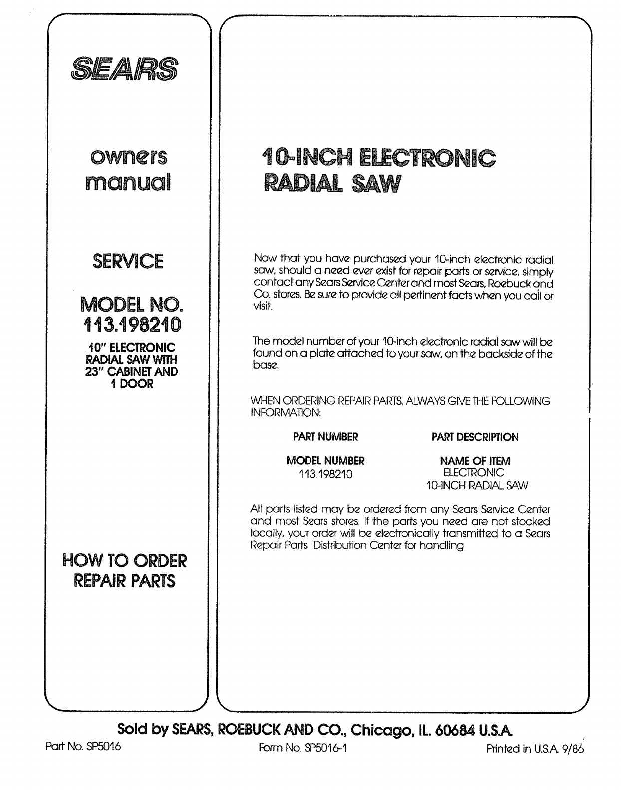
r¸ ,,,ll
SERVICE
10" ELECTRONIC
RADIALSAWWITH
23" CABINETAND
IDOOR
HOW TO ORDER
REPAIRPARTS
I
Now that you have purohas_d your 10-inch eleclTonic radial
saw, should a need ever exist for repair pars or sen4ce, simply
contact any S_ars Sen/ice C_nter and most Sears, Roebuck and
Co. stores. Be sure to provide al! pertinent facts when you cail or
visit.
The model number of your 10-inch electronic radial sc_,vwill be
found on a plate affached to you_-sc_,,_,on the backside of the
base
WHEN ORDERING REPAIR PARTS,ALWAYS Give THEFOLLOWING
INFORMATION:
PARTNUMBER PARTDESCRIPTION
MODEL NUMBER
1t3,198210
NAME OF ITEM
ELECTRONIC
tO-INCH RADIAL SAW
All pars listed may be ordered from any S_ars S_n/ice Center
and most S_ars stores. If the parts you need are not stocked
locally, your order will i=xzelectronically transmitted to a &zars
Repair Parts Distribution Center for handling
Sold by SEARS,ROEBUCKAND CO., Chicago, IL 60684 U.S.A.
Part No. SP5016 Form No. SP5016-t Printed in U_S.A 9/86
