Craftsman 113201480 User Manual 50 295 AMP DUAL RANGE ARC WELDER Manuals And Guides L0805139
CRAFTSMAN Welder Manual L0805139 CRAFTSMAN Welder Owner's Manual, CRAFTSMAN Welder installation guides
User Manual: Craftsman 113201480 113201480 CRAFTSMAN CRAFTSMAN 50-295 AMP DUAL RANGE ARC WELDER - Manuals and Guides View the owners manual for your CRAFTSMAN CRAFTSMAN 50-295 AMP DUAL RANGE ARC WELDER #113201480. Home:Tool Parts:Craftsman Parts:Craftsman CRAFTSMAN 50-295 AMP DUAL RANGE ARC WELDER Manual
Open the PDF directly: View PDF ![]() .
.
Page Count: 36
Save This Manual
For Future Reference
MODEL NO.
113.201480
Serial
Number
Model and serial
number may be found
at the rear
of the cabinet.
You should record both
model and serial number
in a safe place for
future use.
CAUTION:
Read
SAFETY
INSTRUCTIONS
carefully
Sold by SEARS,
Part No. 61421
• •i•: i•i::¸:_:::: : ; :• :; :
50-295 AMP
DUAL RANGE
VARIABLE CONTROL
ACARC
eassembly
®operating
®repair parts
ROEBUCK AND CO., Chicago, IL 60684 U.S.A.
Printed ;inU.S.A_
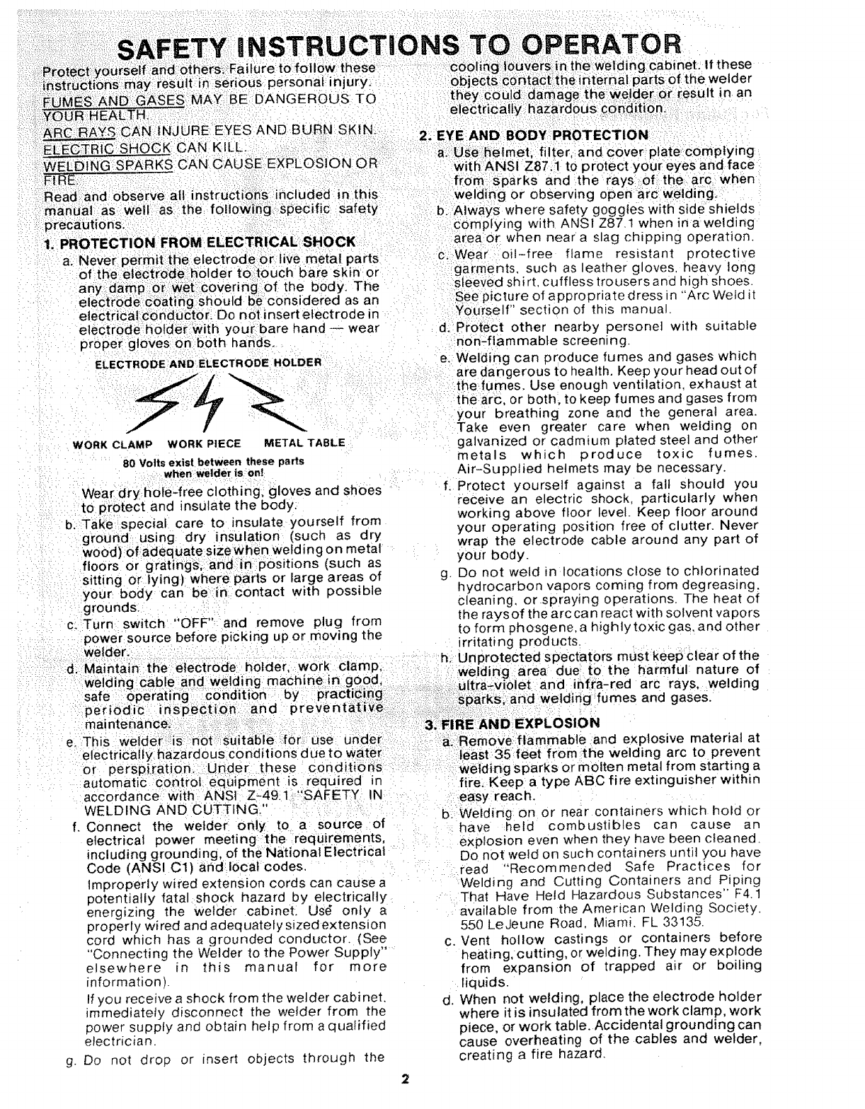
a:. Never permit the electrode or live metal parts
of:the eiectrodeholder t0_t0uch bare sk nor
any: damp:o_ W_eti::covering of the body. The
electrede:cbating slioutd be considered as an
electrical conducltor_ Do n0t insert electrode in
electrode hotde_iWith your bare hand -- wear
pr0pergloVes on both hands.
ELECTRODE AND ELECTRODE HOLDER
WORK CLAMP WORK PIECE METAL TABLE
80 Volts exist between these parts
when welder ison!
Weardry hole_free clothing, gloves and shoes
to protect and insulate the body:
b. Take special care to insulate yourself from
ground using dry insulation (such as dry
wood) of adequate sizewhen welding on metal
floors or gratings, and in:Positions (such as
sitting or lying) where parts or fargo areas of
your body can be in contact with possible
grounds:
c: Turn switch "OFF", and remove plug from
power source before picking up or moving the
welder.
:d. Maintain the electrode: holder, work clamp,
welding cable arid welding machine in good; :i i:
safe Operating i €onditior_ :by :Practii_i_g:!!i: :i:::':
per io d!ic i n S pect ion ::=an d p r e ve n tat ive i!,:_i,:__!.il
e. This Welder':_iis ':not;}:::i_uitable i:iori:_:use
electrically hazardous conditions due to
or persph;atiom Under these c0ndil
automatic control equipment iS required in
accordance: with ANSI Z-49.1:.";SAFETY IN
WELDING AND CUTTING_"
f. Connect the welder on!y to a source of
electrical power meeting the requirements,
including grounding, of the National Electrical
Code (ANSI C1) and local codes,
Improperly wired extension cords can cause a
potentially fatal shock hazard by electrically
energizing the Welder cabinet. Us_ only a
properly wired and adequately sized extension
cord which has agrounded conductor. (See
"Connecting the WeJder to the Power Supply ....
elsewhere in this manual for more
information).
If you receive a shock from the welder cabinet.
immediately disconnect the welder from the
power supply and obtain help from a qualified
electrician.
g. Do not drop or insert objects through the
area or when near a slag chipping operation.
c, Wear oil-free flame resistant protective
garments, such as leather gloves heavy long
sleeved shirt, cuffless trousers and high shoes.
See picture of appropriate dress in "Arc Weld it
YOurself" section of this manual.
d. Protect other nearby persone] with suitable
nOn-flammable screening.
e. Welding can produce fumes and gases which
are dangerous to health. Keep your head out of
the fumes. Use enough ventilation, exhaust at
the arc, or both, to keep fumes and gases from
your breathing zone aod the general area.
Take even greater care when welding on
galvanized or cadmium plated steel and other
metals which produce toxic fumes.
Air-Supplied helmets may be necessary.
f. Protect yourself against a fall should you
recewe an electric shock, particularly when
working above floor level. Keep floor around
your operating position free of clutter. Never
wrap the electrode cable around any part of
your body.
g. Do not weld in locations close to chlorinated
hydrocarbon vapors coming from degreasing.
cleaning, orspraying operations. The heat of
the rays of the arc can react with solvent vapors
to form phosgene, a highlytoxic gas. and other
irritating products.
h. nprotected spectators must keepclear of the
area due to the harmful nature of
et and infra-red arc rays, welding
and weldirig fumes and gases.
a::Remove:flammable and explosive material at
ieast 35 feet from the welding arc to prevent
welding sparks or molten metal from starting a
fire. Keep a type ABC fire extinguisher within
.easy reach.
b. Welding on or near containers which hold or
have held combustibles can cause an
explosion even when they have been cleaned.
Do not weld on such containers until you have
read "Recommended Safe Practices for
Welding and Cutting Containers and Piping
That Have Heid Hazardous Substances" F4.1
available from the American Welding Society.
550 LeJeune Road, Miami. FL 33135.
c. Vent hollow castings or containers before
heating, cutting, or welding. They may explode
from expansion of trapped air or boiling
liquids.
d. When not welding, place the electrode holder
where it is insulated from the work clamp, work
piece, or work table. Accidental grounding can
cause overheating of the cables and welder,
creating a fire hazard.
e. Neverconnecttheworkcableor clamptoany
objectbutthe workpieceor meta_worktable.
Connectingto otherobjectssuchasbuilding
ground can cause stray currents to flow,
resultingin overheatingor fire.
4. PREVENTATIVE MAINTENANCE
a. Never apply power to the welder with any part
of the ,cabinet" removed. Position on-off
switch in "off" position and disconnect welder
from the power supply before doing
maintenance work inside the machine.
Removal of the welder cabinet should be done
onty by a qualified service technician.
b. Before connecting the welder power cord to
the receptacle, check the following:
1. Inspect the power cord and welding cables
for cuts or burns and make sure blades and
ground pin on the plug are straight.
2. Inspect "ON-OFF" switch leverfor cracks or
broken parts.
3, Inspect electrode holder jaw insulators for
cracks or broken parts.
c. Never weld anything on or to the welder
cabinet, as a burn through may cause
transformer failure.
d. If any part of your welder is malfunctioning or
has been damaged or broken, such as switch,
cables, helmet, electrode holder, cease
operation immediately and disconnect welder
from the power source and turn switch "OFF"
until the particular part is properly repaired or
replaced.
5. ADDITIONAL SAFETY INFORMATION
a. For additional safety information, purchase
copies of "Practice for Occupational and
Educational Eye and Face Protection" (ANSI
Z87.1), "Safety in Welding and Cutting" (ANSI
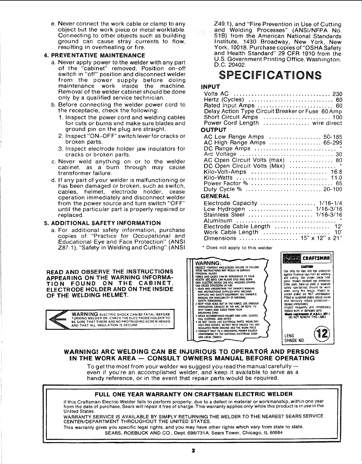
READ AND OBSERVE THE INSTRUCTIONS
APPEARING ON THE WARNING INFORMA-
TION FOUND ON THE CABINET,
ELECTRODE HOLDER AND ON THE INSIDE
OF THE WELDING HELMET.
i
t.,_ WARNING ELECTR,CSHOCKCA.BEFATAL!BeFOa_I
TURNING WELDE R ON, CHECK THE ELECTRODE HOLDER TO 1
BE SURE THAT THERE ARE NO PROTRUDING SCRE W HEADS
_1_ AND THAT ALL INSULATION iS SECURE _ _ :" '_
Z49.1), and "Fire Prevention in Use of Cutting
.... , and ,Welding Processes" (ANSIiNFPA No.
518) from the American National Standards
Institute, 1430 Broadway, New York, New
York, 10018. Purchase copiesof"OSHA Safety
and Health Standard" 29 CFR 1910 from the
U.S. Government Printing Office, Washington,
D.C. 20402.
SPECiFICATiONS
INPUT
Volts AC.. ............................ ..... 230
Hertz (Cycles) .;..... ...................... 60
Rated Input Amps .......................... 60
Delay Action Type Circuit Breaker or Fuse 60Amp
Short Circuit Amps ....................... 100
Power Cord Length ................ wire direct
OUTPUT
AC Low Range Amps .................. 50-185
AC High Range Amps .................. 65-295
DC Range Amps ............................ *
Arc Voltage ................................ 30
AC Open Circuit Volts (max) ............... 80
DC Open Circuit Volts (Max) ................ *
Kilo-Volt-Amps .......................... 16,8
Kilo-Watts ............................... 11.0
Power Factor %............................ 65
Duty Cycle % .......................... 20-100
GENERAL
Electrode Capacity ................... 1/16-1/4
Low Hydrogen ...................... 1/16-3/16
Stainless Steel ...................... 1/16-3/16
Aluminum .................................. *
Electrode Cable Length ................... 12'
Work Cable Length ....................... 10'
Dimensions .................... 15" x 12" x 21"
" Does not apply to this welder
LENS (_
SHADE NO.
WARNING! ARC WELDING CAN BE iN3URIOUS TO OPERATOi_ AND PERSONS
_N THE WORK AREA -- CONSULT OWNERS MANUAL BEFORE OPERATING
To get the most from your welder we suggest you read the manual carefully--
even if you're an accomplished welder, and keep it available to serve as a
handy reference, or in the event that repair parts would be required.
FULL ONE YEAR WARRANTY ON CRAFTSMAN ELECTRIC WELDER
if this Craftsman Etectric Welder fails to perform properly, due to a defect in materiaJ or workmanship,within oneyear
from thedate of purchase, Sears will repair it free of charge. This warranty applies only whilethis product is inuse inthe
United States.
WARRANTY SERVICE IS AVAILABLE BY SIMPLY RETURNING THE WELDER TO THE NEAREST SEARS SERVICE
CENTER/DEPARTMENT THROUGHOUT THE UNITED STATES.
This warranty gives you specific legal rights, and you may have other rights wtiich vary from state to state_
SEARS, ROEBUCK AND CO., Dept, 698/731Ai Sears Tower, Chicago, IL 60684
OPERATING!I_INSTR_CTI ONS
Warranty _ : ii !:.! :i _.:_i:::.:... :.:;_:.:. _.i _. !., _i 3
Getting tO ::'.. :,:_:i. :. 4
Unpacking and C_cki"gGontents :; : .!;;...... 4
Operating ContrOls ................. 6
0 ........................ 7
T ................. 8
ARC ..... 1-1
WELDING ROD SPECIFICATIONS ......... 2-1
REPAIR PARTS ............................ 2-6
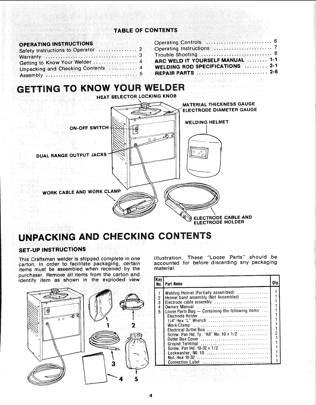
GETTING TO: KNOW YOUR WELDER
HEAT SELECTOR LOCKING KNOB
ON-OFF SWITCH \
\
DUAL RANGE OUTPUT _"
\
MATERIAL THICKNESS GAUGE
_ELECTRODE DIAMETER GAUGE
WELDING HELMET
!
WORK CABLE AND WORK CLAMP
-%
ELECTRODE CABLE AND
ELECTRODE HOLDER
UNPACKING AND CHECKING CONTENTS
SET-UP I NSTRUCTIONS _
This Craftsmanwelder:is shipped complete in one
carton_ 'In order to:facilitate packaging; ce_'tain
items must be assembled when received by the
purchaser. Remove:all items from the carton and
identify item as _shown in the exploded view
illustration. These "Loose Parts" should be
accounted for before discarding any packaging
material.
Key
No. Part Name 'Oty
_:__ _i 1 WeidingHetmet(Partia,lyassembted) ...............
2 Helmet band assembly (Not Assembled) .............
3 Electrode cable assembly ..........................
4 Owners Manual ...................................
5 Loose Parts Bag -- Containing the following items: ,..
--__ ii 1 "_ 2 E,ectrodeHoJder ..............................
1/4" Hex "L" Wrench .............................
WorkClamp .:....................................
Screw. Pan Hd: Ty, "AB" No. 10 x1/2 ..............
iOutlet BoxCover. ...... ..: ....................... '
• G_oundTerminal ...... ;.-:...........................
i]Screw PahHdi10-32 x'_t2 .. .... ,................
J Nut, Hex 10:32 ..... ::..:_..: .... ..................
, ConnectionLabel ;... :.. .........
1
1
t
1
1
1
1
I
I
2
t
t
1
1
1
1
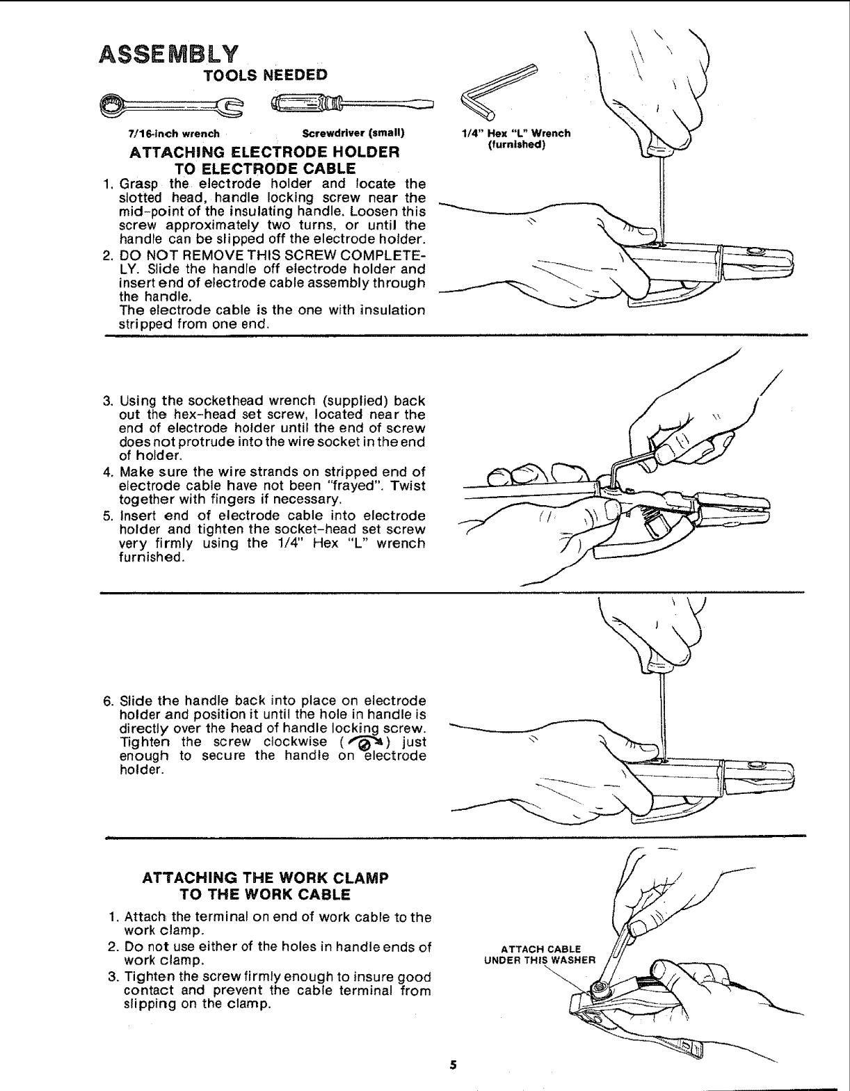
ASSEMBLY
TOOLS NEEDED
@
,
,
7/16-inch wrench Screwdriver (small)
ATTACHING ELECTRODE HOLDER
TO ELECTRODE CABLE
Grasp the electrode holder and locate the
slotted head, handle locking screw near the
mid-point of the insulating handle. Loosen this
screw approximately two turns, or until the
handle can be slipped off the electrode holder.
DO NOT REMOVE THIS SCREW COMPLETE-
LY. Slide the handle off electrode holder and
insert end of electrode cable assembly through
the handle.
The electrode cable is the one with insulation
stripped from one end.
1/4" Hex "L" Wrench
(furnished)
3. Using the sockethead wrench (supplied) back
out the hex-head set screw, located near the
end of electrode holder until the end of screw
does not protrude into the wire socket in the end
of holder.
4. Make sure the wire strands on stripped end of
electrode cable have not been "frayed". Twist
together with fingers if necessary.
5. Insert end of electrode cable into electrode
holder and tighten the socket-head set screw
very firmly using the 1/4" Hex "L" wrench
furnished.
6. Slide the handle back into place on electrode
holder and position it until the hole in handle is
directly' over the head of handle Iock__nngscrew.
Tighten the screw clockwise (,"_.) just
enough to secure the handle on e_ectrode
holder.
ATTACHING THE WORK CLAMP
TO THE WORK CABLE
1. Attach the terminal on end of work cable to the
work clamp.
2. Do not use either of the holes in handle ends of
work clamp.
3. Tighten the screw firmly enough to insure good
contact and prevent the cable terminal from
slipping on the clamp.
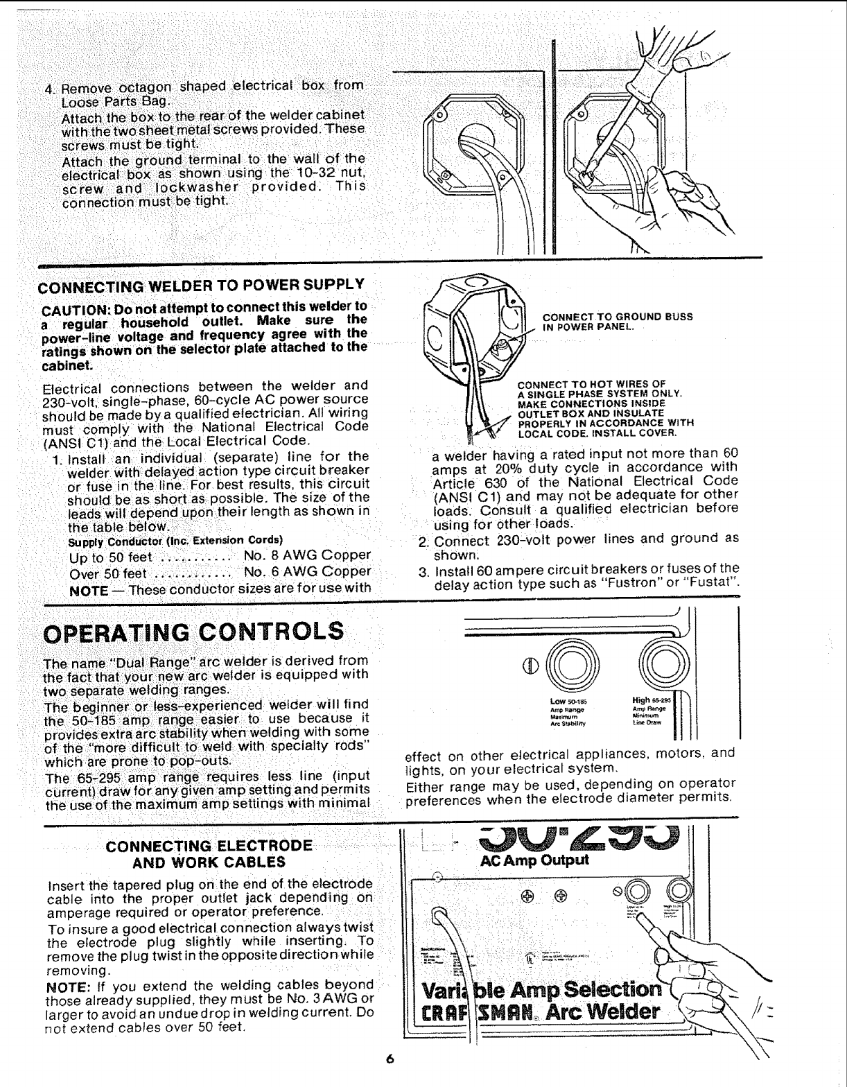
CONNECTING WELDER TO POWER SUPPLY
CAUTION: Do not attempt to connect this welder to
a regular household outlet. Make sure the
power-line voltage and frequency agree with the
ratings shown on the selector plate attached tothe
cabinet_
Electrical connections between the welder and
230-volt, single-phase, 60-cycle AC power source
should be made by a qualified electrician. All wiring
must comply With the National Electrical Code
(ANSI Ct)a'nd theLocal Electrical Code.
1. Install an individual (separate)line for the
welder With;delayed action type circuit breaker
or fuse in the line:: For best results, this circuit
should: boas shortas possible. The size of the
leads:will depend Upon:their length as shown in
the: table belOW_:i:::_
Suppty C0nduCtor (i.c. Exteriston Cords)
Up to 50 feet ._- ........ No. 8 AWG Copper
Over 50:feet .._ .......... No. 6 AWG Copper
NOTE .-These conductor sizes are for use with
i ............ ,.,, , , ., ,
2_
3.
H
CONNECT TO GROUND BUSS
IN POWER PANEL,
CONNECT TO HOT WIRES OF
A SINGLE PHASE SYSTEM ONLY.
_ _ MAKE CONNECTIONS INSIDE
OUTLET BOX AND INSULATE
PROPERLY IN ACCORDANCE WITH
LOCAL CODE. INSTALL. COVER,
awelder having arated input not more than 60
amps at 20% dutY cycle in accordance with
Article 630 of the National Electrical Code
(ANSI C1) and may not be adequate for other
loads. Consult a qualified electrician before
using for other loads.
Connect 230-vott power lines and ground as
shown.
Install 60 am pete circuit breakers or fuses of the
delay action type such as "Fustron" or "Fustat".
L ,
LOW r_O-18,_
Am_ Rar_ge
M=xLmum
Arc $_I_#_v
effect on other electrical appliances, motors, and
lights, on your electrical system.
Either range may be used, depending on operator
preferences when the electrode diameter permits.
CON NECTING ELECTRODE
AND WORK CABLES
Insert the tapered plug on the end of the electrode
cable into the proper outlet jack depending on
amperage required or operator preference.
To insure a good electrical connection always twist
the electrode plug slightly while inserting. To
remove the Dlug twist in theoppositedirection while
removing.
NOTE: If you extend the welding cables beyond
those already supplied, they must be No. 3 AWG or
larger to avoidan unduedrop in welding current. Do
not extend cables over 50 feet.
L
AC Amp Output
leArnp se
$MRN Arc Welder
__J
6
Connectthework clamp to the piece to be welded,
(to complete the electrical circuit) or to the welding
table itself provided it is metallic or wilt conduct
electricity!
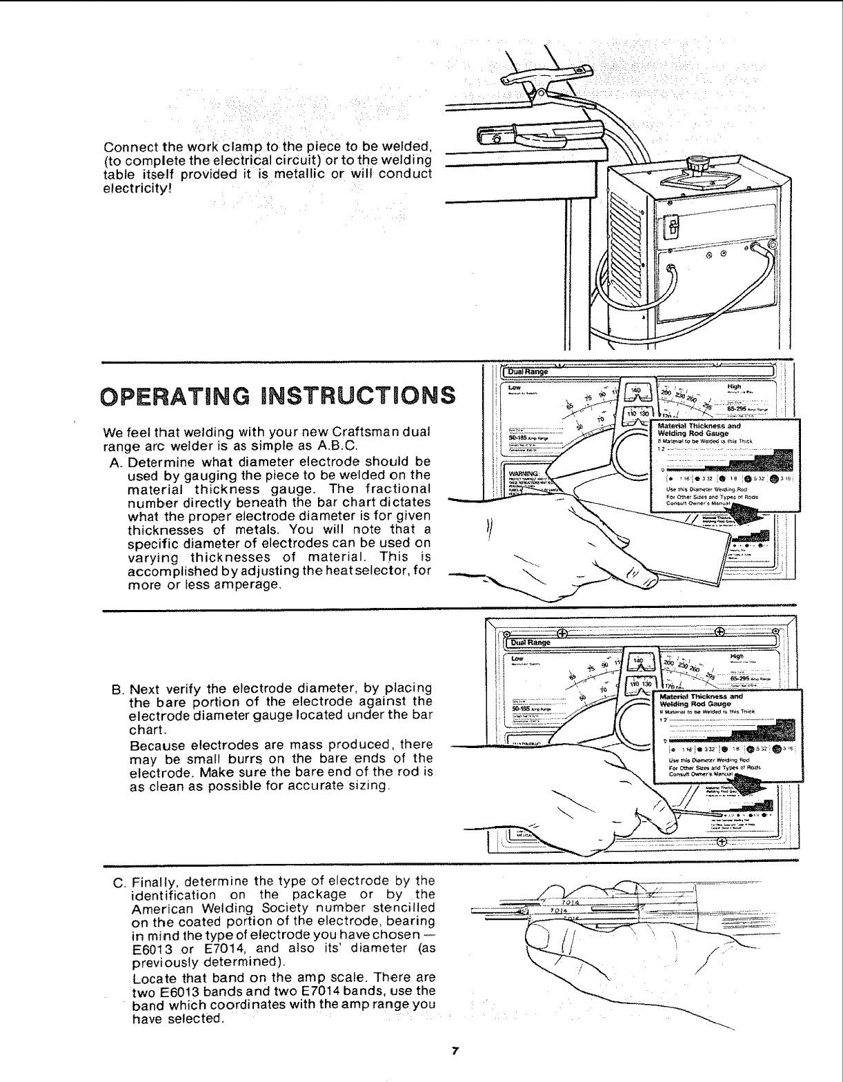
OPERATING INSTRUCTIONS
We feel that welding with your new Craftsman dual
range arc welder is as simple as A.B.C.
A. Determine what diameter electrode should be
used by gauging the piece to be welded on the
material thickness gauge. The fractional
number directly beneath the bar chart dictates
what the proper electrode diameter is for given
thicknesses of metals. You will note that a
specific diameter of electrodes can be used on
varying thicknesses of material. This is
accomplished by adjusting the heat selector, for
more or less amperage.
B. Next verify the electrode diameter, by placing
the bare portion of the electrode against the
electrode diameter gauge located under the bar
chart.
Because electrodes are mass produced, there
may be small burrs on the bare ends of the
electrode. Make sure the bare end of the rod is
as clean as possible for accurate sizing.
C. Finally, determine the type of electrode by the
identification on the package or by the
American Welding Society number stencilled
on the coated portion of the electrode, bearing
in mind the type of electrode you have chosen
E6013 or E7014, and also its' diameter (as
previously determined).
Locate that band on the amp scale. There are
two E6013 bands and two E7014 bands, use the
band which coordinates with the amp rangeyou
have selected.
7
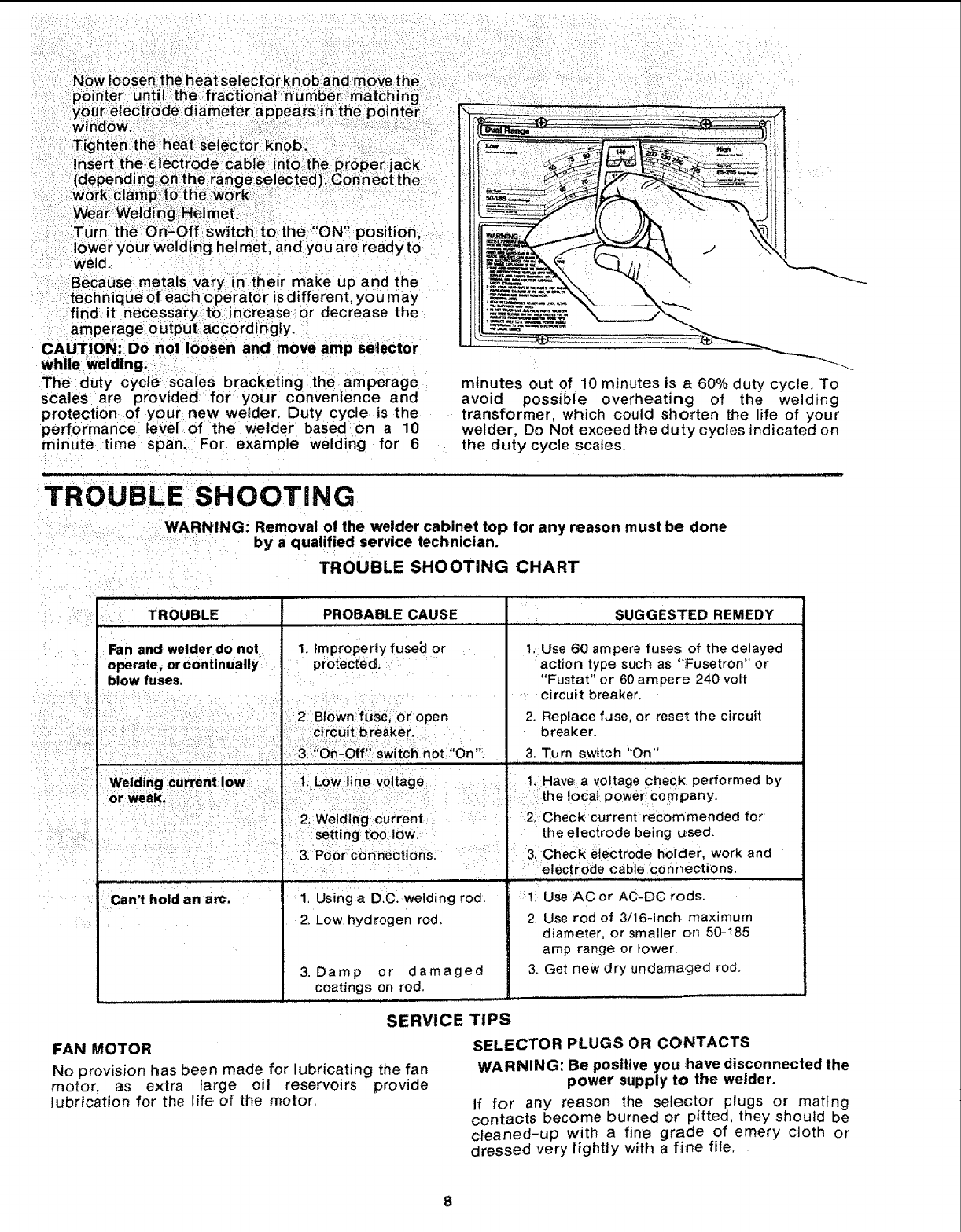
weld.
Because metals vary {n their make up and the
technique of each operat0r is different, you may
find it necessary to: increase: or decrease the
amperage output accord!ngly.
CAUTION: Donol loosen and move amp se|ector
while welding..
The duty cycle scales bracketing the amperage
sca':les are provided for your convenience and
protection of your new weGder. Duty cycle is the
performance level of the welder based on a 10
minute time span. For example welding for 6
minutes out of 10 minutes is a 60% duty cycle. To
avoid possible overheating of the welding
transformer, which could shorten the life of your
welder, Do Not exceed the duty cycles indicated on
the duty cycle scales.
TROUBLE SHOOTING
WARNING: Removal of the welder cabinet top for any reason must be done
by a q ualified service technician.
TROUBLE SHOOTING CHART
TROUBLE , SUGGESTED REMEDY
Fan and welder do not 1. Improperly fuse_l or 1. Use 60 ampere fuses of the delayed
operate; orcontinually : protected, action type such as "Fusetron" or
blow fuses. ' : "Fustat" or 60 ampere 240 volt
I................ circuit breaker.
i 2, Blown:fuse,; or open 2. Replace fuse, or reset the circuit
Circuitbreaker. breaker.
.3,?"OPi:-0ff":switch not "On". 3. Turn switch _'On".
i; Welding current low: !i:i i':: ':_ilLow ine voi'tage , "t. Have a voltage 'c'heck performed by
or:weak; :!; :/ : :the local powerl Company.
.... : I: Welding current I 2! Check current recommended for
: : : !: setting:too Iowl Ithe electrode being used.
...... :- :: i I3 P0or:c0nnect ons I3: Check eiectrode holder work and
; I : ..... .... : electrode Cable Connections.
Can't hold an arc.
PROBABLE CAUSE
1. Using a D.C. welding rod.
2. Low hydrogen rod.
i 1: Use ACor AC-DC rods.
2. Use rod of 3/16-inch maximum
diameter, or smaller on 50-185
amp range or lower.
3. Get new dry undamaged rod.
3. Damp or damaged
coatings on rod.
SERVICE TIPS
FAN MOTOR
No provision has been made for lubricating the fan
motor, as extra large oil reservoirs provide
lubrication for the life of the motor.
SELECTOR PLUGS OR CONTACTS
WARNING: Be positive you :have disconnected the
power supply to the welder.
If for any reason the selector plugs or mating
contacts become burned or pitted, they should be
cleaned-up with a fine grade of emery cloth or
dressed very lightly with a fine fife.
8
fl
%_
A COMPREH ENSIVE
GUIDE FOR YOUR
NEW CRAFTSMAN
ARC WELDER AND
WHAT iT W=ILL DO
CONTAt NS:
INFORMATION ABOUT
o VARIOUS TYPES OF RODS
o USEFUL ACCESSORIES
e TIPS ON CUTTING, WELDING
AND BRAZING
,,J
Form No. SP574+5 t.1
_i_?/:-: ¸ _:!. ......
_iii_!i.i___
TABLE OF _cONTENTs
Page
Your WelderandWhat it Will Do ............. 1-3
Howthe CraftSmanCOntactRod SimplifiesWelding 1-3
WhatHappensWhenYou Weld? .. .......... 1-3
RoadeefareWeiding .:i._._,.!..:,....i.,.... 1-4
LearnBy Doing ........................... 1-5
PositionWelding ......................... 1-11
Cast4ronWelding....; .... ...... . 1-14
.a,dSu ,,=jn.Wor,,C. .gEd,-IIZ 1-15
TheTwin CarbonArc Torch ............... 1-16
CuttingandOtherMiscellaneousOperations ... 1-17
Read this Manual carefully for additional welding information.
._ ••• H• •••• H•¸
SEARS, ROEBUCK AND COMPANY
AND S|MPSONS-SEARS LIMITED
1.2
YOUR WELDER and what H wil/ do . .
Your CRAFTSMAN Arc Welderisa sturdilyconstructedandthoroughlytestedmachineengineeredto
give many years of efficient trouble-free service. It is listed by Underwriters' Laboratories,
incorporated,which meansthat it passesal! requirementsof safety, fire hazardand temperaturerise
limitsasspecifiedin their Standardfor Transfer-TypeArc-WeldingEquipment.
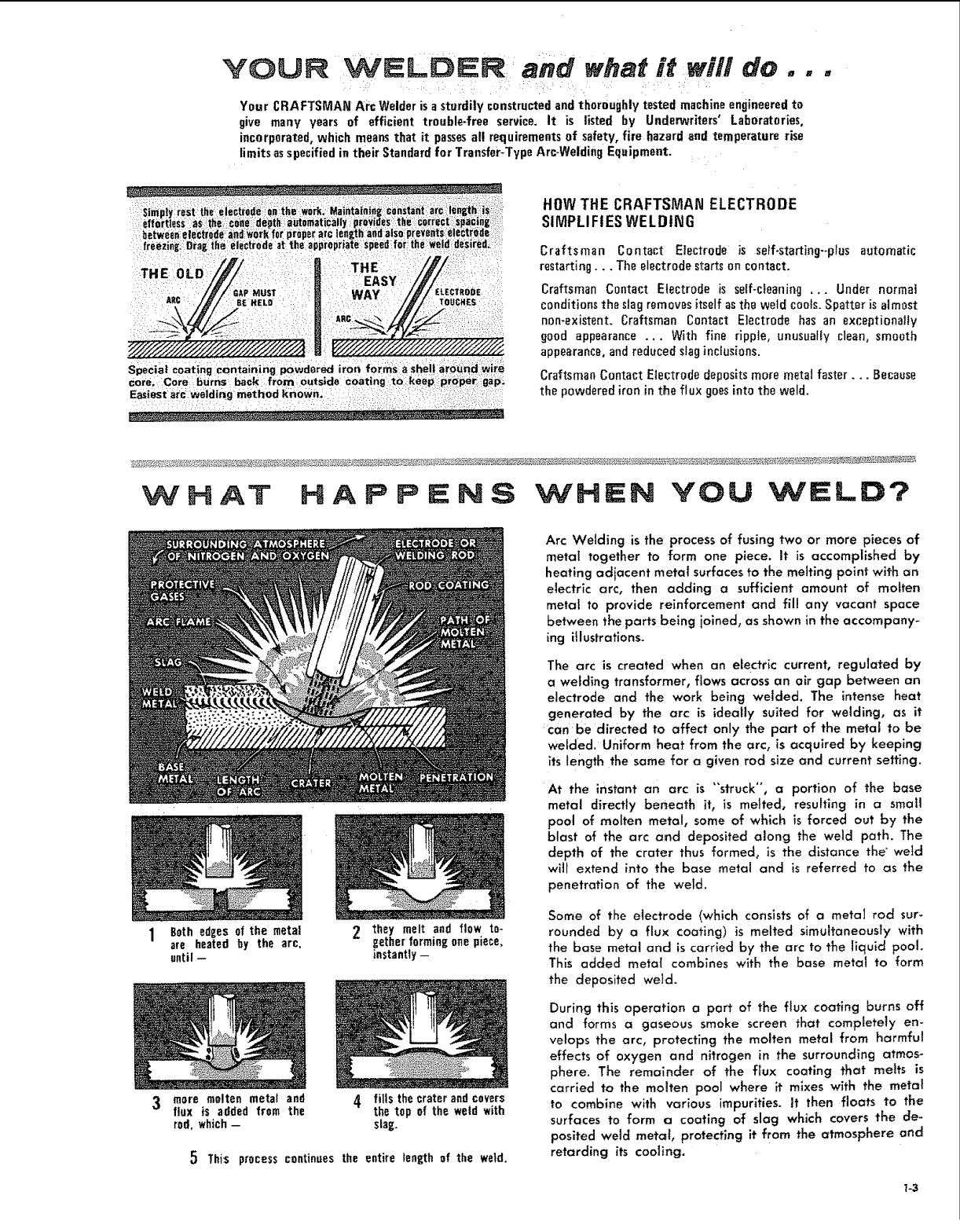
Sreply rest the electrode :an the iwork, Maintaining consta_nt:arcilength::is _
effortless as the cOne_:depth aOtomatiCaly pt+oydes the correct! spacin[i
between electr#de:a:ndlw0rkfor proper arc length andals0 p{ev _ht_,e ei_trede
freezinj Drag the electrode at the appropriate speed f0r the Weld:desired_:
E
,ec/_'/_# MUSe' WAY /Ji''LoEC_OOe
Special coating containing powdered iron forms ashell around wire
Core, Core burns back from outside coating to keep proper: go:p;
Easiest arc_welding method known.
HOWTHE CRAFTSMAN ELECTRODE
SIMPLIFIES WELDING
Craftsman Contact Electrode is se/f-starting--p{usautomatic
restarting... The electrode startson contact.
Craftsman Contact Electrode is self-cleaning... Under normal
conditionstheslagremovesitselfastheweldcools.Spatter is almost
non-exiszent. Craftsman Contact Electrode has an exceptionally
good appearance... With fine ripple, unusuafiyclean, smooth
appearance,and reducedslaginclusions.
CraftsmanContact Electrodedepositsmore metal faster... Because
the powderedironin the flux goesintothe weld.
W H AT H A P P NS WHEN YOU WELD?
1Bath edges of the metal
are heated by the arc,
until --
mare molten metal and
flux is added from the
rod, which-
2_hey melt and flow to-
gether forming onepiece,
instantly -
4 fills the crater and covers
the top of the weld with
sing.
5 This process continues the entire length of the weld.
Arc Welding is the process of fusing two or more pieces of
metal together to form one piece. It is accomplished by
heating adjacent metal surfaces to the melting point with an
electric arc, then adding a sufficient amount of molten
metat to provide reinforcement and fill any vacant space
between the parts being ioined, as shown in the accompany-
ing itlustrations.
The arc is created when an electric current, regulated by
a welding transformer, flows across an air gap between an
electrode and the work being welded. The intense heat
generated by the arc is ideally suited for welding, as it
:can be directed to affect only the part of the metal to be
welded, uniform heat from the arc, is acquired by keeping
its length the same for a given rod size and current setting.
At the instant an arc is "struck", a portion of the base
metal directly beneath it, is melted, resulting in a small
pool of molten metal, some of which is forced out by the
blast of the arc a_d deposited along the weld path. The
depth of the crater thus formed, is the distance the" weld
will extend into the base metal and is referred to as the
penetration of the weld.
Some of the electrode (which consists of a metal rod sur-
rounded by a flux coating) is melted simuhaneousty with
the base metal and is carried by the arc to the liquid pool
This added mete! combines with the base metal to form
the deposited we}.d.
During this operation a part of the flux coating burns off
and forms a gaseous smoke screen that completely en-
ve!ops the arc, protecting the molten metal from harmful
effects of oxygen and nitrogen in the surrounding atmos-
phere. The remainder of the flux coating that melts is
carried to the molten pool where it mixes with th_ metal
to combine with various impurities. It then floats to the
surfaces to form a coating Of slag which covers the de-
posited weld metc_{, protecting it from the atmosphere and
retarding its coollng.
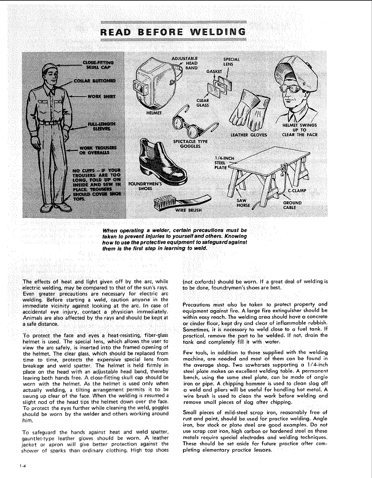
When operating a welder, certain precautions must be
taken to prevent injuries to yourseff and others. Knowing
ha w to use the protective equipment to safeguard against
them is the first step in learning to weld.
The effects of heat arid:tight given off by the arc, while
electr €I welding, may belcompared to that of the sun's rays.
Even greater precautions are necessary for electric arc
welding. Before starting a weld, caution anyone in the
immediate vicinity against looking at the arc. In case of
accidental eye injury, contact a physician immediately.
Animals are also affected by the rays and should be kept at
a safe distance.
To protect the face and eyes aheat-resisting, i fiber-glass
he met sused. The special lens,:i which alloWs the User to
view the arc safely, is inserted into the framed opening of
the helmet. The clear glass, which should be replaced from
time to time, protects the expensive special lens from
breakage and weld spatter. The helmet is held firmly in
place on the head with an adjustable head band, thereby
leaving both hands free. A close-fitting skull cap should be
worn with the helmet. As t.he helmet is used only when
actually welding, a tilting arrangement permits it to be
swung up clear of the face. When the welding is resumed a
slight nod of the head tips the helmet down over the face.
To protect the eyes further while cleaning the weld, goggles
should be worn by the welder and others working around
him.
To safeguard the hands against heal and weld spatter,
gauntlet-type leather gloves shou|d be worn. A leather
jacket or apron will give better protection against the
shower of sparks than ordinary clothing. High top shoes
(not oxfords) should be worn. If a great deal of welding is
to be done, foundrymen's shoes are best.
PrecaOtions must also be taken to protect property and
equipment against fire. A large fire extinguisher should be
within easy reach. The welding area should have a concrete
or cinder floor, kept dry and clear of inflammable rubbish.
Sometimes, it is{necessary to weld dose to a fuel tank. If
practical; rem0ve-the part to be welded. If not, drain the
tank and comptetelyfil! it with water,
Few tools, in addition to those supplied with the welding
machine, are needed and most of them can be found in
the average shop. Two sawhorses supporting a 1/4-inch
steel plate makes an excellent welding table. A permanent
bench, using the same steel plate, can be made of angle
iron or pipe: A Chipping hammer is used to clean slag off
a weld and pliers will be useful for handling hot metal. A
wire brush is used to clean the work before welding and
remove small pieces of slag after chipping.
Small pieces of mild-steel scrap iron, reasonably free of
rust and paint, should be used for practice welding. Angle
iron, bar stock or plate steel are good examples. Do not
use scrap cast iron, high carbon or hardened steel as these
metals require special electrodes and welding techniques.
These should be set aside for future practice after com-
pleting elementary practice lessons.
_4
LEARN BY DO|NG
DIRECTIOH
OFWELD
Experience has proven that short periods of practice at
regutar intervals are the best way to teach yourself how
to weld. As learning to weld is simply a process of trial
and error, all practice work should be done on scrap metal
that can be discarded. Do not attempt to make repairs on
valuable equipment until you have satisfied yourself that
your practice welds are of good appearance arid free of
slag or gas inclusions. Remember, what you fail to tearn
while practicing, must be ]earned through a series of
mistakes and rewetds later on.
A comfortable body position is important when learning,
as tensed muscles will result in fatigue and lack of control.
Sit on a tow stool and grasp the electrode holder in one
hand with the cable drawn across the lap. Allow enough
slack to move the holder freely and yet keep the weight
and drag of a long length of cable from becoming tiring.
The work connection is as much a part of the welding
circuit as the cable and electrode holder, A poor work
connection can render the best welding equipment
inefficient. When using a table with a steel top, fasten the
tug of the work cable to it securely with a bolt or C-c_amp,
so that any piece of iron placed on the table top will be
properly grounded. If a steel table is not used, connect the
work cable directly to the work with a work clamp or belt.
Select a fairly large piece of steel plate approximately
1/4-inch thick and clamp it to the table top to prevent it
from lifting, should the electrode stick or "freeze" when
/
/
tl
f
/
Figure 1
To strike an arc, scratch the
end of the rnd on the plate
and then quickly raise ap-
proximately 1/8-inch.
I90':
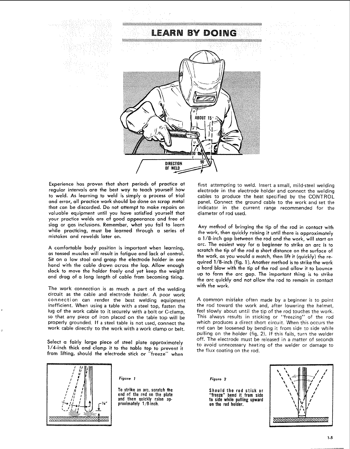
first attempting to weld. Insert a small, mild-steel welding
electrode in the electrode holder and connect the welding
cables to produce the heat specified by the CONTROL
panel. Connect the ground cable to the work and set the
indicator in the current range recommended for the
diameter of rod used.
Any method of bringing the tip of the rod in contact with
the work, then quickly raising it until there is approximately
a 1/8-inch gap between the rod and the work, will start an
arc. The easiest way for a beginner to strike an arc is to
scratch the tip of the rod ashort distance on the surface of
the work, as you would a match, then lift it (quickly) the re-
quired 1/8-inch (fig. 1). Another method is to strike the work
ahard blow with the tip of the rod and aIIow it to bounce
up to form the arc gap. The important thing is to strike
the arc quicNy and not allow the rod to remain in contact
with the work.
A common mis{ake often made by a beginner is to point
the rod toward the work and, after lowering the helmet,
feel slowly about until the tip of the rod touches the work.
This always results in sticking or "freezing" of the rod
which produces a direct short circuit. When this occurs the
rod can be loosened by bending it from side to side while
pulling on the holder (fig. 2). If this fails, turn the welder
off. The electrode must be released in a matter of seconds
to avoid unnecessary heating of the welder or damage to
the flux coating on the rod.
Figure 2
Should the rod stick ur
"freeze" bend it frum side
to side while pulling upward
un the rod holder.
\\
\\\
_/?/////////,_
i j HJInn
Ii/
.......s/ /.
i :V /
!!
/
t
9 ¢
_/_ ¢?'///////1,,_
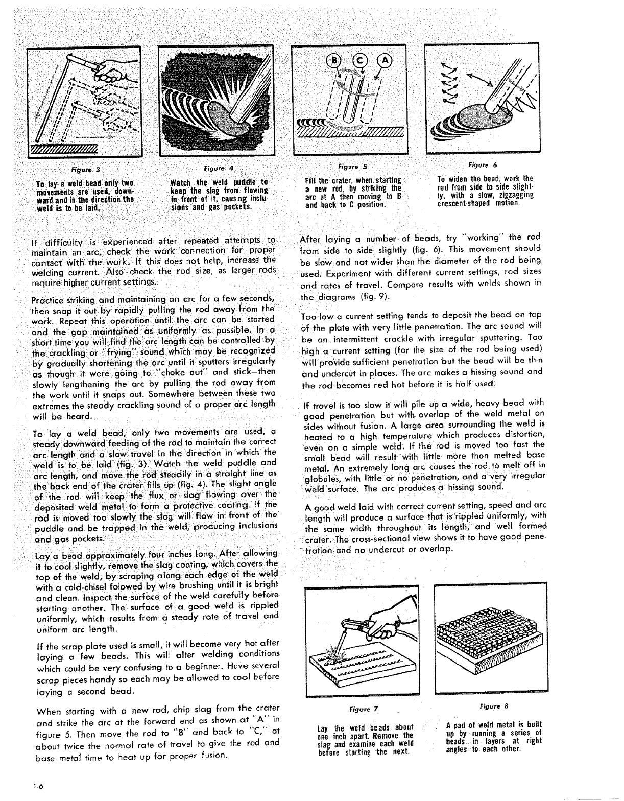
Figure 3..... Figure 4 ;'
TO lay a weld:bead _nly two Watch the weld puddle ta
movements are ,sod. down* keep the slag from flowing
ward andin the eirectiOnthe in front of it. causing ioclu-
weld is to be:laid. i ....: : ....... :sions and gas pockets
:, i _ " _: :
Figure 5 Figure 6
Fill the crater, whenstarting
a new rod, by std.king the
arc at A then moving to B
and back to C pnsitinnl
1"owiden the bead, work the
rod from side tn side sliEht-
ly_ with a slow, zigzagging
crescent-shaped motinn.
If difficulW is experienced after repeated attempts t9
maintain an arc; Check:the work.connection for •proper
contact with the work. If this _does not help, increase the
welding current. AlSocheck the rod size, as [arger rods
require higher current settings.
Practice Striking and maintc_ining an arc for a few seconds,
by gradually shorteninglthe arc until it sputters irregularly
as though it were going to _'choke out" and stick-then
slowly {engthening the arc by pulling the rod away from
the work until it snaps out. Somewhere between these two
extremes the steady crackling sound of a proper arc length
will be heard.
To lay aweld bead,! only two movements are used, a
steady downward feeding of the rod to maintain the correct
arc lef_gth and a :slave:travel in the direction in which the
i.ay a bead approximately four inches 10ng. After allowing
it to cool slightly, iemove the slag coating, whichcovers the
top of the weld; foy Scraping ai0ng:each edge of the weld
with o Cold-chisel to]owed by wire brushing until it is bright
and clean. Inspect the surface of the weld carefully before
starting another. The surface of a good weld is rippled
uniformly, which results from a steady rote of travel and
uniform arc length
If the scrap plate used is small, it will become very hot after
laying a few beads. This will alter welding conditions
which could be very confusing to a beginner. Have several
scrap pieceshandy so each may be allowed to coo! before
laying a second bead.
When starting with anew rod, chip slag from the crater
and strike the arc at the forward end as shown at "A" in
figure 5. Then move the rod to "B" and back to "C," at
about twice the normal rate of travel to give the rod end
base metal time to heat up for proper fusion.
After laying a number of beads, try "working" the rod
from side to side slightly (fig. 6), This movement should
be slow and not wider than the diameter of the rod being
used. Experiment with different current settings, rod sizes
and rates of travel. Compare results with welds shown in
the diagrams (fig. 9).
Too low a current setting tends to deposit the bead on top
of the plate with very little penetration. The arc sound will
be an intermittent crackle with irregular sputtering. Too
high a current setting (for the size of the rod being used)
will provide sufficient penetration but the bead will be thin
and undercut in places. The arc makes a hissing sound and
the rod becomes red hot before it is half used:
If travel is too slow it will pile up a wide, heavy bead with
good penetration but witff overlap of the weld metal on
sides without fusion. A large area surrounding the weld is
heated to a high temperature which produces distortion,
even on a simple we{d. If the rod is moved too fast the
small bead will result with little more than melted base
metal An extremety long arc causes the rod tc melt off in
globules, with little or no penetration, and a very irregular
Weld surface. The arc produces ahissing sound.
A good weld laid with correct current setting, speed and arc
length wifl produce a surface that is rippled uniformly, with
the same width throughout its length, and wet! formed
crater:, The cross-sectional view shows it to have good pene-
tration; and no undercut or overlap.
i i
Figure 7
Lay the weld beads about
one inch aparL Remove the
stag and examine each weld
before starting the nexL
Figure 8
A pad of weld metal is built
up by running a series of
beads in layers at right
anglesto each other.
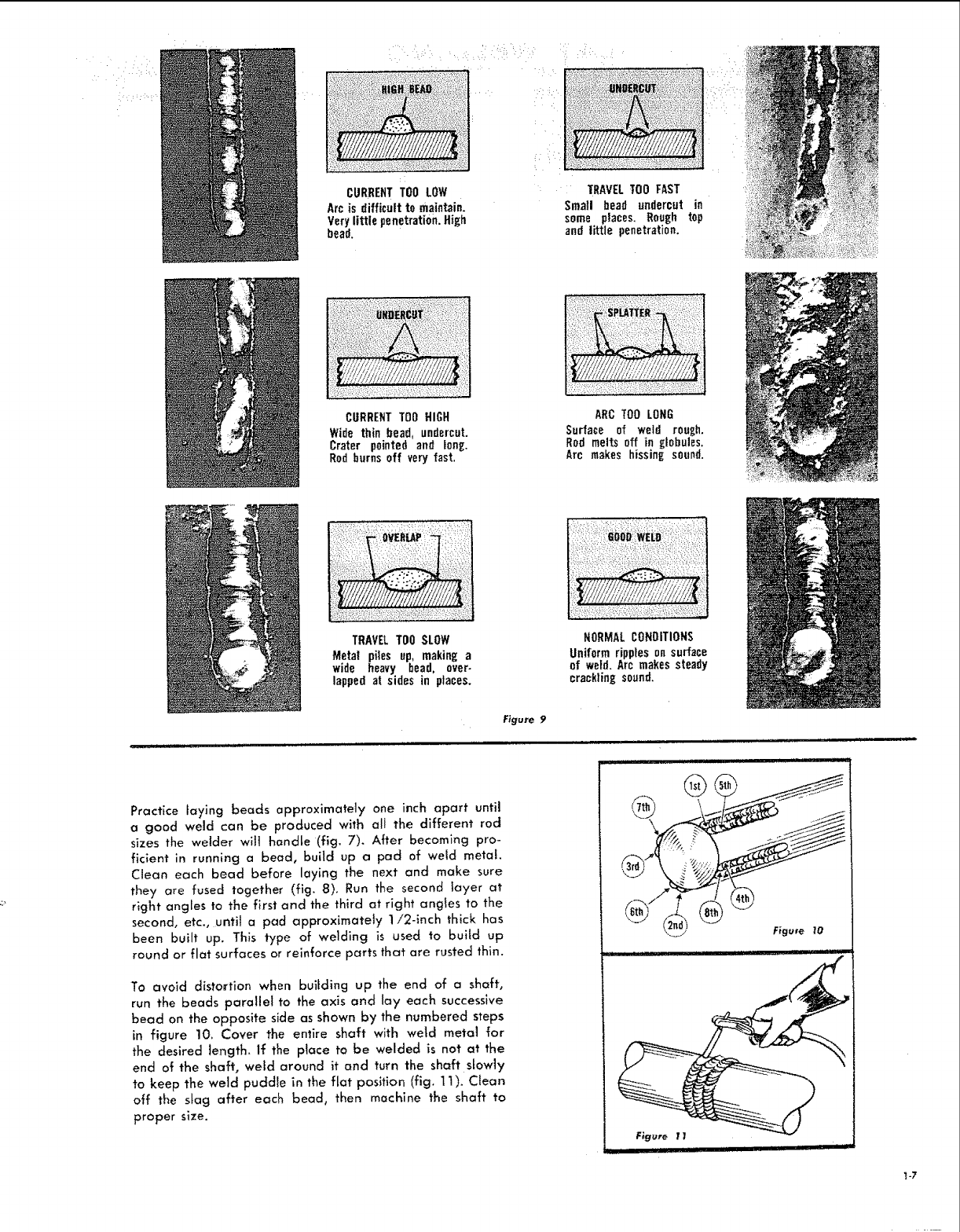
CURRENTTOO LOW
Arc is difficult to maintain.
Verylittle penetration.High
bead.
TRAVELTOO FAST
Small bead undercut in
some places. Rough top
and little penetration.
CURRENTTOO HIGH
Wide thin bead, undercut.
Crater pointed and tong.
Rod burns off very fast.
T.........
ARC TOO LONG
Surface of weld rough.
Rod melts off in globules.
Arc makes hissing sound.
TRAVELTOOSLOW
Metal piles up, making a
wide heavy bead, over-
lapped at sides in places.
NORMALCOHOITIONS
Uniform ripples on surface
of wetd. Arc makes steady
crackling sound.
Figure 9
Practice laying beads approximate]y one inch apart until
agood weld can be produced with aft the different rod
sizes the welder wit] handle (fig. 7). After becoming pro-
ficient in running a bead, build up a pad of weld meta!.
Clean each bead before laying the next and make sure
they are fused together (fig. 8). Run the second layer at
right angles to the first and the third at right angles to the
second, etc., until a pad approximately 1i2-1nch thick has
been built up. This type of welding is used to buiid up
round or flat surfaces or reinforce parts that are rusted thin.
To avoid distortion when building up the end of a shaft,
run the beads parallel to the axis and lay each successive
bead on the opposite side as shown by the numbered steps
in figure 10. Cover the entire shaft with we{d metal for
the desired length. If the place to be welded is not at the
end of the shaft, weld around it and turn the shaft slowly
to keep the weld puddle in the flat position (fig. 11). Clean
off the stag after each bead, then machine the shaft to
proper size.
,i ii i, ....................
......... i Ll' I!
_-7
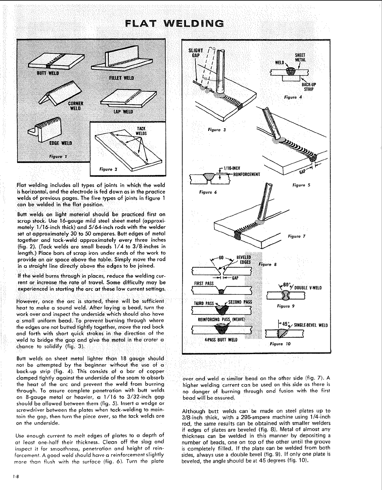
Flat welding includes all types of joints in which the weld
ishorizontal; and the electrode is fed d own as inthe practice
Welds Of previous pages_ The five types of ioints in figure 1
can b_ welded in the flat position.
Butt welds on light material should be practiced first on
scrap Stocki Use 16-gauge mild steel sheet meta! (approxi-
mately t/16_inch thick) and 5/64-inch rods with the welder
set at approximately 30to 50 amperes. Butt edges of metal
together and tack-weld approximately every three inches
(fig. 2). (Tack welds are small beads I/4 to 3/8-inches in
length.) Place bars of scrap iron under ends of the work to
provide an air space above the table. Simply move the rod
in a straight line directly above the edges to be joined.
If theweld burns thrQugh in places, reduce the welding cur-
rent or increase :the: rate of travel. Some difficulty may be
experienced in starting the arcat these low current settings.
However, once the arc iS :started, there will be sufficient
heat to make a sound weld. After laying a bead; turn the
work over and inspect the underside which: should also have
a small uniform bead. To prevent burning through where
the edges are not butted tightly together, move the rod back
and forth with short quick strokes inthe direction of the
weld to bridge the gap and glVe the metat inithe:crater a
chance to solidify (fig,:3)i
Butt welds on sheet metal lighter than 18 gauge should
not be attempted by the beginner without the use of a
back-up strip (fig. 4). This consists of a bar of copper
clamped tightly against the underside of the seam to absorb
the heat of the arc and prevent the weld from burning
through. To assure complete penetration with butt welds
an 8-gauge metc_t or heavier, a !/16 to 3/32-inch gap
should be aJlowed between them (fig. 5). Insert awedge or
screwdriver between the plates when tack-welding to main-
tain the gap, then turn the piece over, so the tack welds are
on the underside.
Use enough current to muff edges of plates to a depth of
at feast one-haft their thickness. Clean off the slag and
inspect it for smoothness, penetration and height of rein-
forcement. Agood wetd should have a reinforcement slightly
more than flush with the surface (fig. 6). Turn the plate
STRIP
Figure 4
Figure 3
1/16-INCH
REIKFORCEMENT
Figure 6 p_ Figure 5
F_gure 7
-'Y-/' EOGES::-r_ ure
f:ii!ii: ;?
GAP _i_i:_?-ii?;,
oo
4-PASSBUTTWELO
E V-WEt_O
Figure 9
k45_p " SINGLE-BEVELWELD
Figure 10
over and weld a similar bead on the other side (fig. 7). A
higher welding current can be used on this side as there is
no danger of burning through and fusion with the first
bead will be assured.
Although butt welds can be made on steel plates up to
3!8-inch thick, with a 295_ampere machine using 1/4-inch
rod, the same results can be obtained with smaller welders
if edges of plates are beveled (fig, 8). Metal of almost any
thickness ca_ be welded in this manner by depositing a
number of beads, one on top of the other until the groove
is completely filled. If the plate can be welded from both
sides, always use a double bevel (fig. 9). If only one plate is
beveted, the angle should be at 45 degrees (fig. 10).
To8
!i •¸ • • ••
UNDERCUT GASPOCKET
F_gure !2
Figure 13
TRAPPEDSLAG PENETRATION
Figure T!
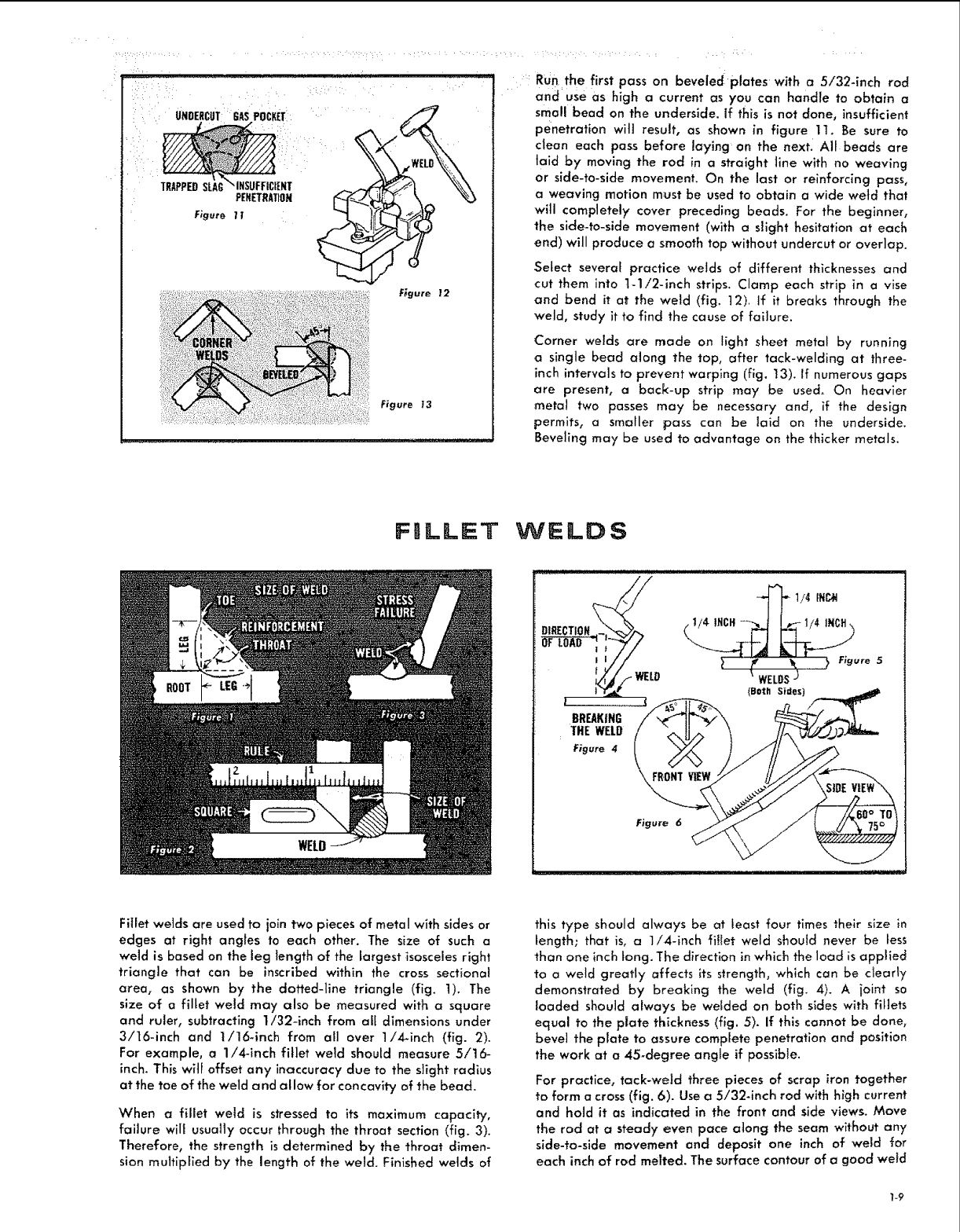
Run the first pass on beveled plates with a 5/32-inch rod
and use as high a current as you can handle to obtain a
small bead on the underside. If this is not done, insufficient
penetration wit] result, as shown in figure 11. Be sure to
clean each pass before laying on the next. Aft beads are
laid by moving the rod in a straight line with no weaving
or side-to-side movement. On the last or reinforcing pass,
a weaving motion must be used to obtain a wide weld that
witl completely cover preceding beads. For the beginner,
the side-to-side movement (with a slight hesitation at each
end) will produce a smooth top without undercut or overlap.
Select severat practice welds of different thicknesses and
cut them into 1-1/2-inch strips. Clamp each strip in a vise
and bend it at the weld (fig. t2). If it breaks through the
weld, study it to find the cause of failure.
Corner welds are made on light sheet metal by running
a single bead along the top, after tack-welding at three-
inch intervals to prevent warping (fig. 13). If numerous gaps
are present, a back-up strip may be used. On heavier
:metal two passes may be necessary and, if the design
permits, a smaller pass can be laid on the underside.
Beveling may be used to advantage on the thicker metals.
FJLLEET WELDS
FRONTFigure 6
Fillet welds are used to join two pieces of metal with sides or
edges at right angles to each other. The size of such a
weld is based on the leg length of the largest isosceles right
triangle that can be inscribed within the cross sectional
area, as shown by the dotted-line triangle (fig. 1). The
size of a fillet weld may also be measured with a square
and ruler, subtracting 1/32-inch from all dimensions under
3/16-inch and 1/16-inch from all over 1!4-inch (fig. 2).
For example, a 1/4-inch fillet weld should measure 5/16-
inch. This will offset any inaccuracy due to the slight radius
at the toe of the weld and allow for concavity of the bead.
When a fillet weld is stressed to its maximum capacity,
failure wiff usually occur through the throat section (fig. 3).
Therefore, the strength is determined by the throat dimen-
sion multiplied by the length of the weld. Finished welds of
this type should always be at least four times their size in
Length; that is, a 1/4-inch fillet weld should never be tess
than one inch long. The direction in which the load is applied
to a weld greatly affects its strength, which can be clearly
demonstrated by breaking the weld (fig. 4). A joint so
loaded should always be welded on both sides with fillets
equal to the plate thickness (fig. 5). if this cannot be done,
bevel the plate to assure complete penetration and position
the work at a 45_degree angle if possible.
For practice, tack-weld three pieces of scrap iron together
to form a cross (fig. 6). Use a 5/32-inch rod with high current
and hold it as indicated in the front and side views. Move
the rod at a steady even pace atong the seam without any
side-to-side movement and deposit one inch of weld for
each inch of rod melted. The surface contour of a good weld
LAP WELDS LAP WELDS
Figure _14 Figure 15
..... i• • • •11 • i • •
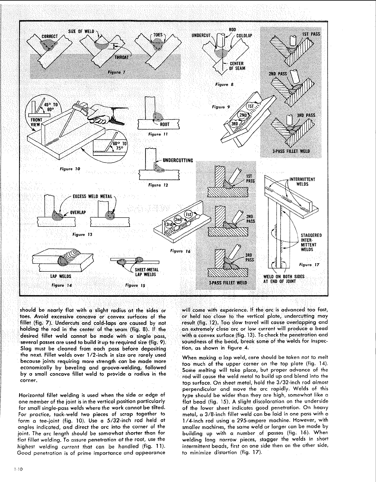
should be nearly flat with aslight radlus at the SidesOr wilL come: with experience, ffthe arc is advanced too fast,
toes. AVoid excessive concave or convex surfaces of the held:t6o: close to the vertical plate, undercutting may
fillet (fig: 7): UnderCuts and Cold-laps are caused by not
holding the rod in the cen_r! 0f the :seam: (fig; 8). ff the
desired fillet weld cannot be ma_e with a Sing!e pass,
several passesare used to build it up to required size (fig_9).:
Slag must be cleaned from each pass before depositing
the next. Fillet welds over 1!2dnch in size a_e rarely used
because ioints requiring more strength can be made more
economically by beveling and groove-welding0 followed
by a small concave fillet weld to provide a radius in the
corner,
Horizontal fillet welding is used when the side or edge of
one member of the joint is in the vertical position particularly
for small single-pass welds where the work cannot be tilted,
Far practice, tack-weld two pieces of scrap together to
form atee-joint (fig. 10). Use a 5/32-inch rod held at
angles indicated, and direct the arc into the corner of the
joint. The arc _ength should be somewhat shorter than for
fiat fillet wetding. To assure penetration at the root, use the
highest welding current that can be handled (fig. 11).
Good penetration is of prime importance and appearance
result (fig. ]2).::Toostow trove] will cause oVerlapping and
an extremely close arc or low current will produce a bead
_iith a convex surface (fig. 13). To check the penetration and
soundnessof the bead, break some of the Weldi_for inspec-
tion, as shown in figure 4.
When making a lap weld, care should be taken not to melt
too much Of the upper corner on the top plate (fig. 14).
sorine melting wil! take place, but proper advance of the
rod will cause the weld metal to build up and blend into the
top surface. On sheet metal, hold the 3/32-inch rod almost
perpendicular and move the arc rapidly. Welds of this
type should be wider than they are high, somewhat like
flat bead (fig. 15). A slight discoloration on the underside
of the lower sheet indicates good penetration. On heavy
metal, (: 3/8-inch fillet weld can be laid in one pass with a
1/4-inch rod using a 295-ampere machine. However, with
smaller machines, the same weld or larger can be made by
building up with a number of passes (fig: 16}. When
welding long narrow pieces, stagger the welds in short
intermittent beads, first on one side then on the Other side,
to minimize distortion (fig. 17).
_-_0
POS}ITtON WELDING
BUTT WELl)
In order to derive the greatest benefits from your we{der,
you should practice until you can make a welded joint
in almost any conceivable position. The ability to do this
is especially useful when making repairs on machinery as
the amount of welding in most cases is small and does not
warrant disassembling the parts to weld them in the flat
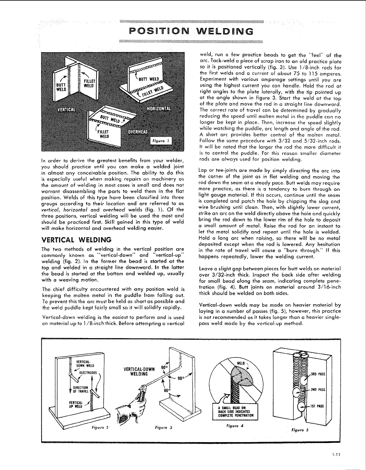
position. Welds of this type have been classified into three
groups according to their location and are referred to as
vertical, horizontal and overhead welds (fig. t). Of the
three positions, vertical welding win be used the most and
should be practiced first. Skill gained in this type of weld
will make horizontal and overhead welding easier.
VERTICAL WELDING
The two methods of welding in the vertical position are
commonly known as "'vertical-down" and "vertical-up*'
welding (fig. 2). In the former the bead is started at the
top and welded in a straight line downward, in the latter
the bead is started at the bottom and welded up, _suaIty
with a weav{ng motion.
The chief difficulty encountered with any position weld is
keeping the molten metal in the puddle from falling out.
To prevent this the arc must be held as short as possible and
the weld puddle kept fairly small so it wilt solidify rapidIy.
Verfica{-down welding is the easiest to perform and is used
on material up to 1/8-inch _hlck. Before attempting a vertical
weld, run a few practice beads to get the "'feel" of the
arc. Tack-weld a piece of scrap iron to an old practice plate
so it is positioned vertically (fig. 31. Use 1/8-inch rods for
the first welds and a current of about 75 to 115 amperes.
Experiment with various amperage settings until you are
using the highest current you can handle. Hold the rod at
right angtes to the plate laterafly, with the tip pointed up
at the angle shown in figure 3. Start the weld at the top
of the plate and move the rod in a straight line downward.
The correct rate of travel can be determined by gradually
reducing the speed unti{ molten metal in the puddle con no
longer be kept in place. Then, increase the speed slightly
while watching the puddle, arc length and angle of the rod.
A short arc provides better controf of the mohen metal.
Fol{ow the same procedure with 3/32 and 5i32_inch rods.
ft will be noted that the larger the rod the more difficuh i_
is to control the puddle. For this reason smaller diameter
rods are a{ways used for position welding.
Lap or tee-joints are made by simply directing the arc into
the corne_ of the joint as in fiat welding and moving the
rod down the seam at a steady pace. _utt welds may require
more practice, as there is a tendency to burn through on
light gauge material Jfthis occurs, continue until the seam
is comp{eted and patch the hole by chipping the slag and
wire brushing until dean. Then, with slightly lower current,
strike an arc on the weld directly above the hole and quickly
bring the rod down to the fower rim of the hole to deposit
a small amount of metal. Raise the rod for an instant to
let the metal solidify and repeat until the hole is welded.
Hotd a long arc when raising, so there will be no metal
deposited except when the rod is lowered. Any hesitation
in the rate of travel wl]i cause a "'burn through." if this
happens repeatedly, lower the welding current.
Leave a siight gap between pieces for butt welds on material
over 3!32-inch thick, inspect the back side after welding
for small bead along the seam, indicating complete pene-
tration (fig. 4). Butt ioints on material around 3!16-inch
thick shou{d be welded on both sides.
vertical-down welds may be made on heavier material by
laying in a number of passes (fig. 51, however, this practice
is not recommended as it takes longer than a heavier single-
pass weld made by the verfica{-up method.
%
VERTICAL-DOWN
WELDING
F_gure 2Figure 3
.... !"!' ' I ' IIIIIIII1,11[,llllll IIII, III
A SMALL_EAgON
BACKST{IFINDICATES
COMPleTE P_IfETRATION
Figure 4
•re5
iiiiiii II IIII I I'11111'
WELOING
Figure 6
F.;gure 8
r ,
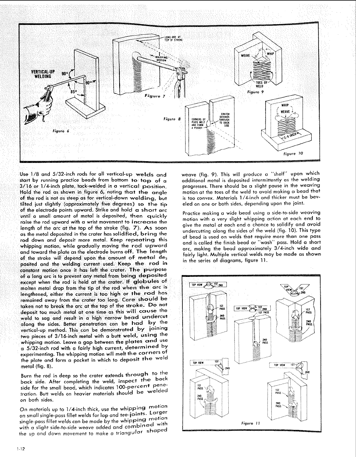
Use 1/8 and 5/32qnch rods for all vertical-up welds and
of the electrode points upward, Strike and hold a short arc
until a small amount of metaf is deposited, th,en quickty
raise the rod upward with a wrist movement to increase the
length of the arc at the top of the stroke (fig, 7), As soon
as the metal deposited in the crater has solidified, bring the
rod Clown and deposit more metal. Keep repeating this
whipping motion_ while gradually moving the rod upward
and toward the plate asthe electrode burns off. The [ength
Figure 9
Figure I0
weave (fig. 9), This will produce a "shelf" _pon which
additional metal is deposited intermittently as the welding
progresses. There shouJd be a slight pause in the weaving
motion at the toes of the weld to avoid making a bead that
is too convex. Materials 1/4-inch and thicker must be hew
eled on one or both sides, depending upon the joint.
Practice making a wide bead using a side-to_side weaving
motion with a very slight whipping action at each end to
give the metat at each end a chance to solidify and avoid
undercutting along the sides of the weld (fig, 10). This type
of bead is used on welds that require more than one pass
and is called the finish bead or "wash" pass. Hold a short
arc, making the bead approximately 3/4-inch wide and
fairly light. Multiple vertical welds may be made c_s shown
in the series of diagrams, figure 11.
along the sides. Better penetration can be had by the
vertical-up method. This can be demonstrated by joining
two pieces of 3/16-inch metal With a butt welcl; using the
whipping motion. Leave a gap between the plates and use
a 5/32-inch rod with a fairly high current, determined by
experimenting. The whipping motion wilt melt the corne_s of
the plate and form a pocket in which to deposit the weld
metal (fig. 8).
Burn the rod in deep so the crater extends through to the
back side. After completing the weld, inspect" the back
side for the smo_Jbead, which indicates ]O0-percent pene-
tration. Butt welds on heavier materlaFs should be welded
on both sides.
On materials up to ]/4-inch thick, use the whipping :motion
on smafJsingle-pass filtet welds for lap and tee-joints. Larger
single-pass fillet wetds can be made by the whipping motion
with astighf side-to-side weave added and combined with
the up and down movement to make a triangular shaped
[ ,
,p,JlL
Figure 17
HORIZONTAL WELDING
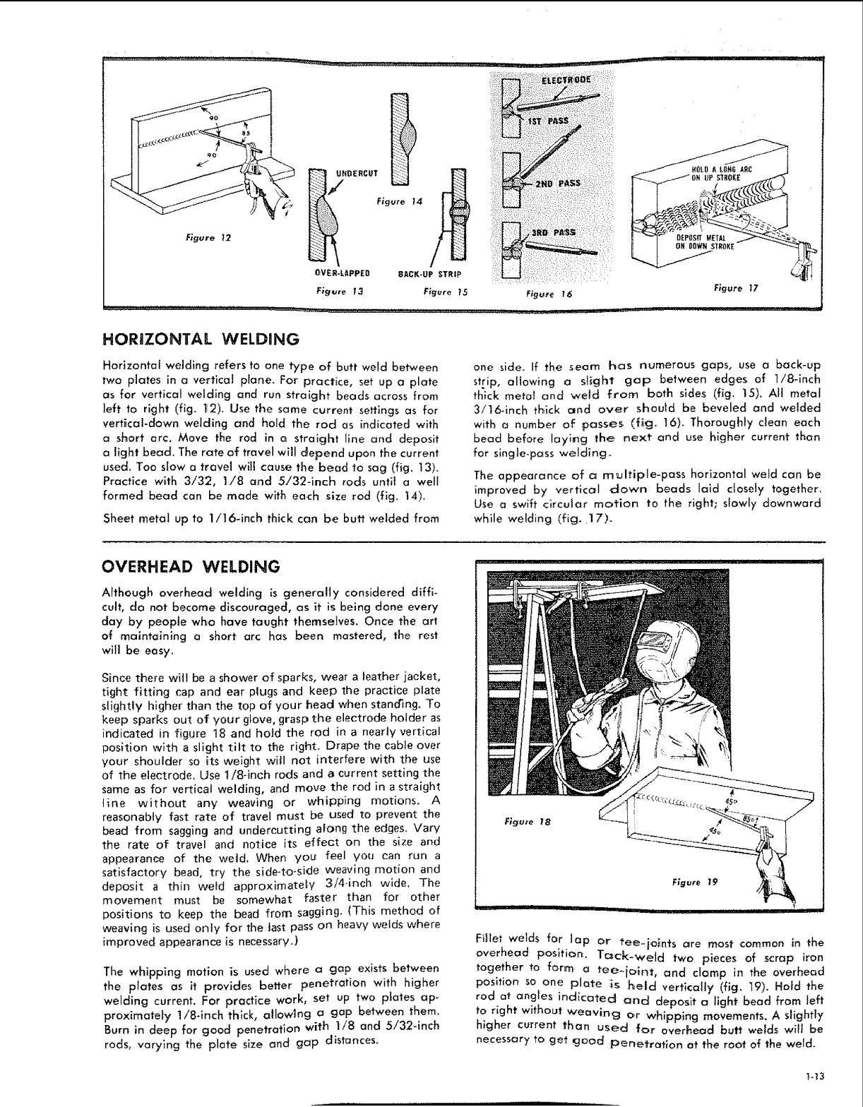
Horizontat welding refers to one type of butt weld between
two plates in a ve_tica] plane. For practice, set up a plate
as for vertical welding and run straight beads across from
]eft to right (fig. t..'2). Use the same current settings as for
verffcal-down welding and hold the rod as indicated with
a short arc. Move the rod in c_ straight line and deposit
alight bead. The rate of travel will c_epend upon the current
used. Too slow a travel wiff cause the bead to sag (fig. t3).
Practice with 3/32, 1/8 and 5/32-inch rods until a well
formed bead can be made with each size rod (fig. 14).
Sheet metal up to 1/16-inch thick can be butt welded from
one side. If the seam has numerous gaps, use a back-up
strip, allowing a sffght gap between edges of 1i8qnch
thick meta! and weld from both sides (fig. 15). All metal
3/16-inch tt_ick and over should be beveled and welded
with a number oF £asses (f_g. 16). Tharough}y dean each
bead before laying the next and use higher current than
for single-pass welding.
The appearance of c_ multiple-pass horizontal weld can be
improved by vertical down beads laid ctosety together.
Use a swift circular motion to the right; slowly downward
while welding (fig. 17)-
OVERHEAD WELDING
Although overhead welding _sgenerally considered diffi-
cult, do not become discouraged, as it is being done every
day by people wl_o have taught themselves. Once the art
of maintaining a short arc has been mastered, the rest
will be easy.
Since there wilt be a shower of sparks, wear a leather jacket,
tight fitting cap and ear plugs and keep the practice plate
slightly higher than the top of your head when stanoqng. To
keep sparks out of your glove, grasp the electrode holder as
indicated in figure 18 and hold the rod in a nearly vertical
position with a slight tilt to the right. Drape the cable over
your shoulder so its weight will not interfere with the use
of the electrode, Use 7/8.inch rods and a current setting the
same as for vertical welding, and move the rod in a straight
line without any weaving or whipping motions. A
reasonably fast rate of travel must be used to prevent the
bead from sagging and undercutting along the edges. Vary
the rate of travel and notice its effect on the size and
appearance of the weld, When you feel you can run a
satisfactory bead, try the side-to-side weaving motion and
deposit a thin weld approximately 3/4-inch wide, The
movement must be somewhat faster than for other
positions to keep the bead from sagging. (This method of
weaving is used only for the last pass on heavy welds where
improved appearance is necessary.)
The whipping motion is used where a gap exists between
the plates as it provides better penetration with higher
welding current. For practice work, set up two plates ap-
proximately 1/8-inch thick, allowlng a gap between them.
Burn in deep for good penetration with 1/8 and 5/32-inch
rods, varying the plate size and gap distances.
F;gu_'e 18
Figure 19
plrll I I
Fillet welds for lap or tee-}o_nts are most common in the
overhead poshiom Tc_ck-wetd two pieces of scrap iron
together to form a tee-joint, and clamp in the overhead
position so one plate ts t_eld vertically (fig. 19). Hofd the
rod at angles indicated and deposit a light bead from left
to right without weaving o,r whipping movements. A slightly
higher current than used fo:r overhead butt welds wifl be
necessary to get goad :penetration at the root of the weld.
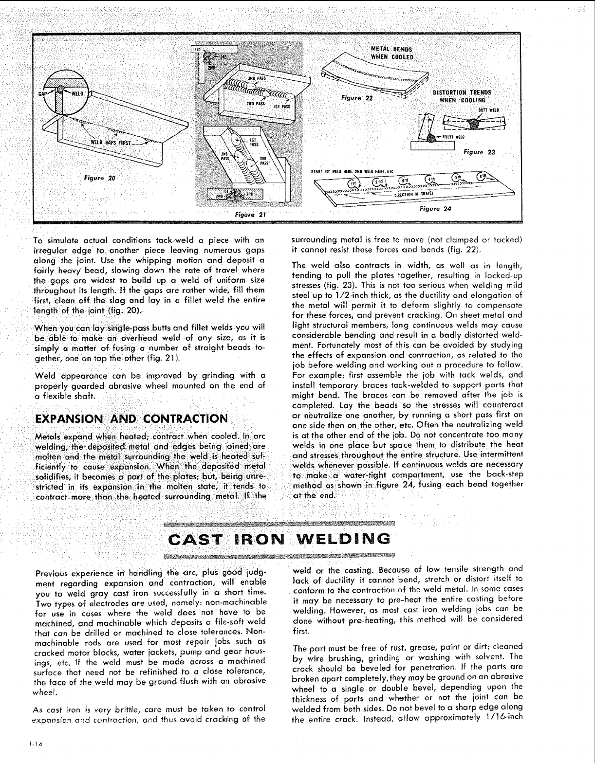
To simulate actual conditions tack-weld a piece with on
irregular edge to another piece leaving numerous gaps
along the ioint. Use the whipping motion and deposit a
fairly heavy bead, slowing down the rate of travel where
the gaps are widest to build up a weld of uniform size
throughout its length. If the gaps are rather wide, fill them
first, clean off the slag and lay in a fillet weld the entire
length of the ioint (fig: 20),
Whei_ y0u can:10y single-pass butts and fillet welds you will
be6bleto, make anioverhead weld of any size, as it is
simply a matter :of fusing a number of straight beads to-
gether, one on top the other (fig. 21).
Weld appearance can be improved by grinding with a
properly guarded abrasive wheel mounted on the end of
a flexible shaft.
EXPANSION; AND. CONTRACTION
Metals expand When_heOted; cOntraCt:when coo_ed. In;arc
:anti: edggs being oined: are
molten and: the metal ::sUrroundirfg: ithe weld is }_eaie(JlsufL
flc entt_/ to cause eX :ansion _Whe:_ ::the :de 0sted meta
:...... p.... :.......... .... P....
solidifies; it becomes €¢parf all the: plates; but, :beingUnr_
stricted in its eXpansi0n in:the molten::state, itI tends: t0
c0ntract_m0re thanlthel heated SurroOn_Jing_metal_ lf the
surrounding metal is free to move (not clamped or tacked)
it cannot resist these forces and bends (fig. 22).
The weld also contracts in width, as well as in length,
tending to pull the plates together, resulting in locked-up
stresses (fig. 23). This is not too serious when welding mitd
steet up to 1!2-inch thick, as the ductility and elongation of
the metal will permit it to deform slightly to compensate
for these forces, and prevent cracking. On sheet metal and
light structural members, lor_g continuous welds may cause
considerable bending and result in o badly distorted weld-
ment. Fortunately most of this can be avoided by studying
the effects of expansion and contraction, as related to the
job before welding and working out a procedure to follow.
For example: first assemble the job with tack welds, and
install temporary braces tack-welded to supporl parts that
m_ght bend. The braces can be removed after the job is
completed. Lay the beads so the stresses witl counteract
or n_utralize one another, by running a short pass first o_
one side then on the other, etc. Often the neutralizing weld
is at the other end of the iob. Do not concentrate too many
welds in one place but space them to distribute the heat
and stresses throughout the entire structure. Use intermittent
Welds whenever, possible, if continuous welds are necessary
to make a: water-tight compartment, use the back-step
method as shown in figure 24, fusing each bead together
at the: end.
CAST: iRON WIELDING
Previous experience in handling the arc, plus good judg-
ment regarding expansion and contraction, will enable
you to weld gray cast iron successfully in o short time.
Two types of electrodes are used, namely: r_on-machinable
for use in cases where the weld does not have to be
machined, and machinable which deposits a file-soft weld
that can be drilled or machined to close tolerances. Non-
machinable rods are used for most repair jobs such as
cracked motor blocks, water iackets, pump and gear hous-
ings, etc. If the weld must be made across a machined
surface that need not be refinished to a close tolerance,
the face of the weld may be ground flush with an abrasive
wheel.
As cast iron is very brittte, care must be taken to controt
expansion and contraction, and thus c_void cracking of the
weld or the casting. Because of low tensile strength and
Jack of ductility it canno_ bend, stretch or distort itself to
conform to the contraction of the weld metal. In some cases
it may be necessary to pre-heat the entire casting before
welding. However, as most cast iron welding jobs can be
done without pre-heating, this method wilt be considered
first.
The part must be free of rust, grease, paint or dirt; cleaned
by wire brushing, grinding or washing with solvent. The
crack shouid be beveIed for penetration. Jf the parts are
broken apart completely, they may be ground on an abrasive
wheel to a single or double bevel, depending upon the
thickness of parts and whether or not the joint can be
welded from both sides. Do not bevel to a sharp edge along
the entire crack. Instead, allow approximately 1i16_inch
!-14
of the fractured surface to line up the two pieces. Tack-weld
or cramp parts in position. If the crack has not separated
the casting, a vee-groove can be chipped out with a dla-
mond_point chisel. Chip an inch or so beyond the visible
ends of the crack as it may extend under the surface. On
cracked water jackets, where only a seal is required, the
depth of the groove need only be one-half the thickness
of the casting.
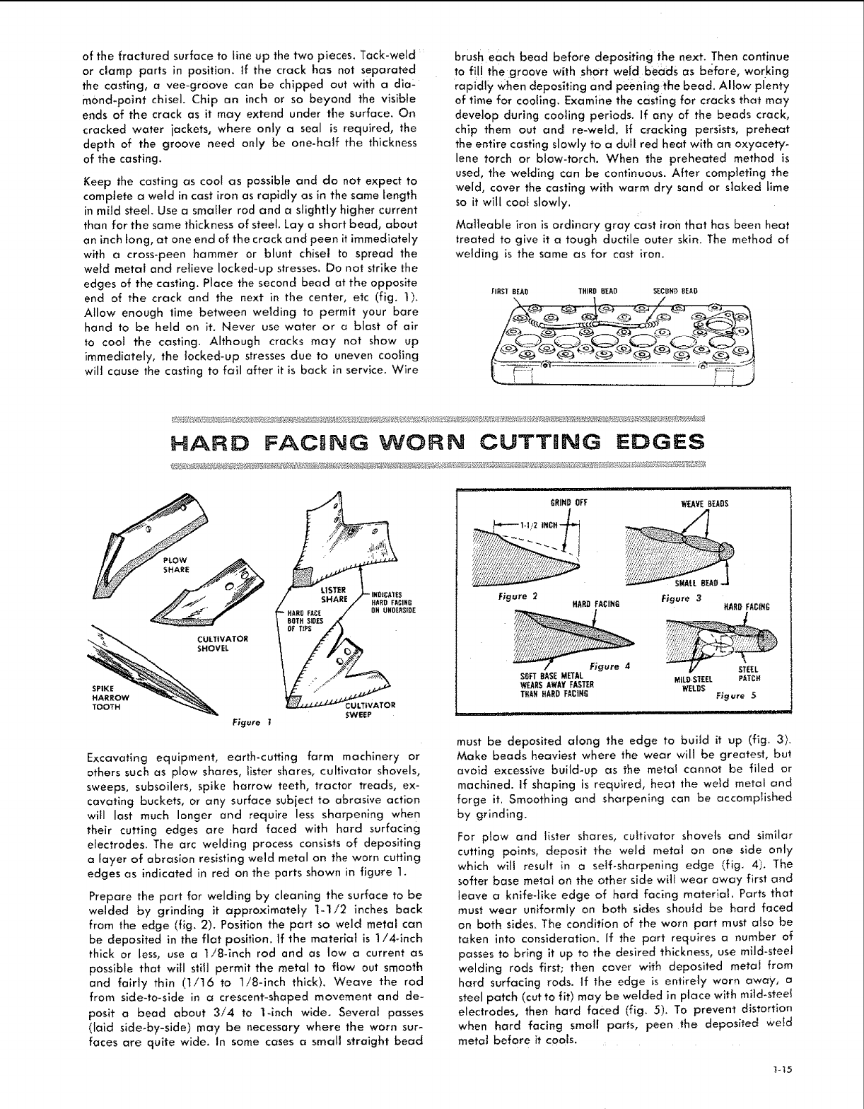
Keep the casting as cool as possible and do not expect to
compiete a weld in cast iron as rapidly as in the same Length
in mild steel. Use a smaWer rod and a slightly higher current
than for the same thickness of steel. Lay a short bead, about
an inch tong, at one end of the crack and peen it immediately
with a cross-peen hammer or blunt chisel to spread the
weld metal and relieve locked-up stresses. Do not strike the
edges of the casting. Place the second bead at the opposite
end of the crack and the next in the center, etc (fig. I).
Allow enough lime between welding to permit your bare
hand to be held on it. Never use water or a blast of air
to cool the casting. Although cracks may not show up
immediately, the tacked-up stresses due to uneven cooling
will cause the casting to fail after it is back in service. Wire
brush each bead before depositing the next. Then continue
to fil! the groove with short weld beads as before, working
rapidly when depositing and peening the bead. Albw plenty
of time for co01ing. Examine the casting for cracks that may
develop during cooling periods. If any of the beads crack,
chip them out and re-wetd, tf c_acking persists, preheat
the entire casting slowly to a dull red heat with ar_ oxyacety-
lene torch or blow-torch. When the preheated method is
used, the welding can be continuous. After completing the
weld, cover the casting with warm dry sand or slaked lime
so it will coof slowly.
Malleable iron is ordinary gray cast iron that has been heat
treated to give it a tough ductile outer skin. The method of
welding is the same as for cast iron.
FIRST BEAD THIRD HEAO SECBH_ READ
FACING WORN CUTTING EDGES
HARD FACING
OR UHOERSI_E
Figure t
Excavating equipment, earth-cutting farm machinery or
others such as plow shares, lister shares, cultivator shovels,
sweeps, subsoilers, spike harrow teeth, tractor treads, ex-
cavating buckets, or any surface subject to abrasive action
will last much longer and require less sharpening when
their cutting edges are hard faced with hard surfaclng
electrodes. The arc welding process consists of depositing
a fayer of abrasion resisting weld metal on the worn cuffing
edges as indicated in red on the parts shown in figure 1.
Prepare the part for welding by cleaning the surface to be
welded by grinding it approximately 1-1/2 inches back
from the edge (fig. 2). Position the part so weld metal can
be deposffed in the flat position. If the material is 1!4-inch
thick or less, use a Ii8-inch rod and as low a current as
possible that will still permit the metal to flow out smooth
and fairly thin (t/t6 to 1/8-inch thick). Weave the rod
from side-to-side in acrescent-shaped movement and de_
posit a bead about 3/4 to 1-inch wide. Severat passes
(lald side-by-side) may be necessary where the worn sur-
faces are quite wide. In some cases a small straight bead
___ ........................ i _, iiiiiiiii
GRIND OFF WEAVEBEADS
,1"'_ 1-1/2 IHCH "_
_MAt.L BEAt]..,.J
F_gure 2 F_gure 3
HARD FACING HARO FACIH_
-- /- F;gure 4__EEL
SOFTBASE METAL .,L!D-S'tEEL PATC,
WEARSAWAYFASTER WELDS
THAH HARDFACIN_ Figure 5
_111,,i,,, i 1,1! ii
must be deposited along the edge to buiJd it up (fig. 3).
Make beads heaviest where the wear will be greatest, but
avoid excessive build-up as the metal cannot be flied or
machined, if shaping is required, heat the wetd metal and
forge it. Smoothing and sharpening can be accomplished
by grinding.
For plow and tister shares, cultivator shovels and similar
cutting points, deposit the weld metat on one side only
which wilt result in a self.sharpening edge (fig. 4). The
softer base metal on the other side will wear away first and
leave a knife-like edge of hard facing materlai. Parts that
must wear uniformly on both sides shoutd be hard faced
on both sides. The condition of the worn part must afso be
taken into conslde_ation. If the part requires a number of
passes to bring it up to the desired thickness, use mild-steel
welding rods first; then cover with deposited metal from
hard surfacing rods. tf the edge is entirely worn away, a
steel patch (cot to fit) may be welded in place with mild_steef
electrodes, then hard faced (fig. 5). To prevent distortion
when hard facing smatl parts, peen the deposited wetd
metat before it cools,
TH TIWIN iCAR B O N I:A R C TO R C H
-[ CAH_ON ELECTRODES
CONNECTTO
SCREY+VS 6ROUHt] AND ©
F+IJF+CTRODE
CABLESOF
EI.ECTROOETIPS A. C+WEILOER
Figure I
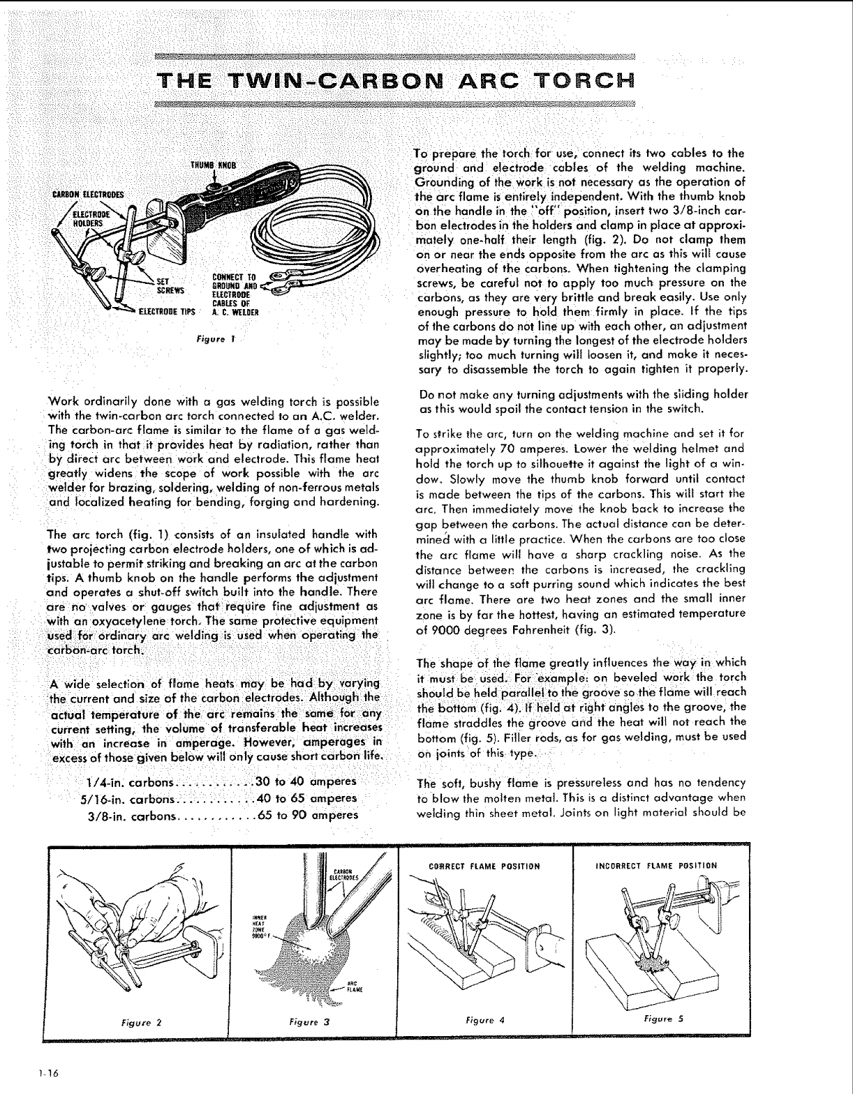
Work ordinarily done with a gas welding torch is possible
with the twin-carbon arc torch connected to an A.C. welder.
The carbon-arc flame is similar to the flame of a gas we]d_
ing torch in that it provides heat by radiation, rather than
by direct arc between work and electrode. This flame heat
greatly widens the scope of work possible with the arc
welder for brazing, soldering, welding of non-ferrous metals
and localized heating for bending, forging and hardening.
The arc torch (fig. 1) consists of an insulated handle with
two projecting carbon electrode holders, one of which is ad-
justable to permit striking and breaking an arc at the carbon
tips, A thumb knob on the handle performs the adjustment
and Operates a shut-off switch built into the handle. There
To prepare the torch for use, connect its two cables to the
ground and electrode cables of the welding machine.
Grounding of the work is not necessary as the operation of
the arc flame is entirely independent. With the thumb knob
on the handle in the !'off" position, insert two 3/8-inch car-
bon electrodes in the holders and damp in pIace at approxi-
mately one-half their length (fig. 2). Do not clamp them
on or near the ends opposite from the arc as this will cause
Overheating of the carbons. When tightening the clamping
screws, be careful not to apply too much pressure on the
carbons, as they are very brittle and break easily. Use only
enough pressure to hold them firmly in p_ace. If the tips
of the carbons do not line up with each other, an adiustment
may be made by turning the longest of the electrode holders
slightly; too much turning will loosen it, and make it neces-
sary to disassemble the torch to again tighten it properly.
Do not make any turning adjustments with the sliding holder
as this would spoil the contact tension in the switch.
To strike the arc, turn on the welding machine and set it for
approximately 70 amperes. Lower the welding helmet and
hold the torch up to silhouette it against the light of a win_
claw. Slowly move the thumb knob forward until contact
is made between the tips of the carbons. This wifl start the
arc. Then immediately move the knob back to increase the
gap between the carbons. The actual distance can be deter-
mined with a little practice. When the carbons are too close
the arc flame will have a sharp crackling noise. As the
distance between the carbons is increased, the crackling
will change to a soft purring sound which indicates the best
:: are na valves or: gauges that:require fine adjustment as arc flame. There are two heat zones and the small inner
i_::: i ::withan oxyacetylene:torch_ The sam epr0tectlve equipment z.one Lsby far thehottest, hav!ng an estimated temperature
at yuuu cfegrees ranrenne_r Lng .3)
::: i na:rya:rC welding::is:usedWhehoperatingthe ' "
:::: i:i: : :::;i::i=i: ::i iii: i The shape Of the flame greatly influences theWay in which
::I:A:wide Selection:lot flame heats may be:iha:d: ,t, mus _:ibel. USed?i °nvbeveled f_a_: twhi; ;:ar_hh
the_Current and size of the Carbon : Sn°U_a: bene!aPara!!e! t° ! e gr: o e so:the . :
acfuai temperature of the bottom (!Ig, r'cghtLahg_est twOiltlheo?r:eOV_ _h_
current seffing; the Volume 0f transferable heat:ir_creaSes : flame straddles th e groo e a
_with an increase in :arn'perage. However; amperages in : bottom (fig: 5). Filler rod s, as for gas welding, must be used
:e_CesS0f thoseglven belbw will Onty cause Short Carb0_ life. On joints at this: type.:.
1/4-ira carbons:_;.:;:.., i, .!L30 to40 amperes The soft, bushy flame is pressureless and has no tendency
:5/16-in. carbons.:_:!.'; !_. _!40 to65 amperes to blow the molten metal This is a distinct advantage when
3/8-in. carbons. 65 to 90 amperes welding thin sheet metal. Joints on light material should be
i ii iii iiii II iiii III !ll iii
Figu_'e 2i
H
i I I III i[ I
/
Figure 3
L
Cg_RECT FLAME POSITION
F_gure 4
iu ........ L_ , i IHI
INCORRECT FLAME POSITION
Figure 5
,11_ ..
1_16
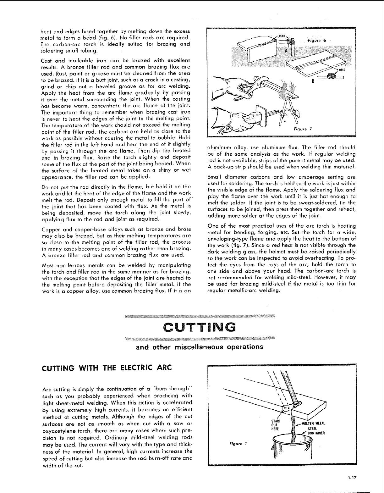
bent and edges fused together by melting down the excess
metal to form a bead (fig. 6). No filler rods are required.
The carbon-arc torch is ideally suited for brazing and
soldering small tubing.
Cast and malleable iron can be brazed with excellent
results. A bronze filler rod and common brazing flux are
used. Rust, paint or grease must be cleaned from the area
to be brazed. If it is a butt joint, such as a crack in a casting,
grind or chip out a beveled groove as for arc welding.
Apply the heat from the arc tame gradually by passing
it over the metal surrounding the joint. When the casting
has become warm, concentrate the arc flame at the joint.
The important thing to remember when brazing cast iron
is never to heat the edges of the ioint to the mehing point.
The temperature of the work should not exceed the melting
point of the filler rod. The carbons are held as close to the
work as possible without causing the metal to bubble. Hold
the filler rod in the left hand and heat the end of it sfghfly
by passing it through the arc flame. Then dip the heated
end in brazing flux. Raise the torch slightly and deposit
some of the flux at the part of the joint being heated. When
the surface of the heated metal takes on a shiny or wet
appearance, the filler rod can be applied.
Do not put the rod directly ;n the flame, but hold it on the
work and let the heat of the edge of the flame and the work
melt the rod. Deposit only enough metal to fill the part of
the joint that has been coated with flux. As the metal is
being deposited, move the torch along the joint slowly,
applying flux to the rod and ioint as required.
Copper and copper-base alloys such as bronze and brass
may also be brazed, but as their melting temperatures are
so close to the melting point of the filer rod, the process
in many cases becomes one of welding rather than brazing.
A bronze filler rod and common brazing flux are used.
Most non.ferrous metals can be welded by manipulating
the torch and fiHer rod in the same manner as for brazing,
with the exception that the edges of the joint are heated to
the melting point before depositing the filer metal. ,:If the
work is a copper alloy, use common brazing flux. If it is an
aiumlnum alloy, use aluminum flux. The filler rod should
be of the same analysis as the work. If regular welding
rod is not avaifable, strips of the parent metal may be used.
A back-up strip should be used when welding thin material
Small diameter carbons and }ow amperage setting are
used for soldering. The torch is held so the work is just within
the visible edge of the flame. Apply the soldering flux and
play the flame over the work untt it is just hot enough to
melt the solder. If the ioint is to be sweat-soldered, tin the
surfaces to be joined, then press them together and reheat,
adding more solder at the edges of the joint.
One of the most practicaJ uses of the arc torch is heating
metal for bending, forging, etc. Set the torch for a wide,
enveloping-type flame and apply the heat to the bottom of
the work (fig. 7). Since a red heat is not visible through the
dark welding glass, the helmet must be raised periodically
so the work can be inspected to avoid overhec_ting. To pro-
tect the eyes from the rays of the arc, hold the torch to
one side a:nd above your head. The carbon-arc torch is
not recommended for welding mild-steel. However, it may
be used for brazing mild-steel if the metat is too thin for
regular metallic-arc welding,
CUTTING
and olher miscellaneous operations
CUTTING WITH THE ELECTRIC ARC
Arc cutting is simply the continuation of a "burn through"
such as you probab]y experienced when practicing with
light sheet-metal welding. When this action is accelerated
by using extremely high currents, it becomes an efficient
method of cutting metals. Affhough the edges of the cut
surfaces are not as smooth as when cut with osaw or
oxyacetylene torch, there are many cases where such pre-
cision is not required. Ordinary mild-steel welding rods
may be used. The current will vary with the type and thick-
ness of the material. In general, high currents increase the
speed of cutting but also increase the rod burn-off rate and
width of the cut.
i 11 i1,,111
START
C_T
HERE
Figure I __
_MOLTEN METAL.
'STEEL
RTAIHER
i,11 ii ii i !1 iii ,I
t-17
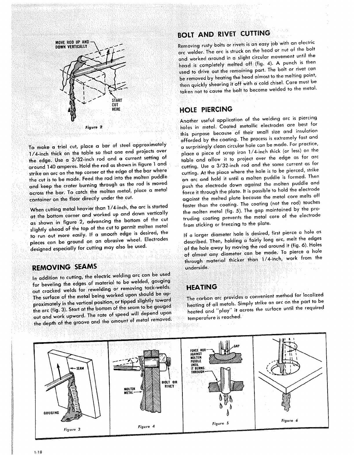
START
CUT
HERE
Figure 2
To make a trial cut, place a bar of steel approximately
1/4-inch thick on the table so that one end proiects over
the edge._ Usea 3/32-inch rod and a current setting of
around 140 amperes. Hold the rod as shown in figure 1 and
strike an arc on the top corner at the edge of the bar where
the cut isto be made. Feed the rod into the molten puddle
and: keep the Crater burning through as the rod is moved
across the bar. To catch the molten metal, place a metal
container onthe floor directly under the cut.
When cutting metal heavier than 1/4-inch, the arc is started
at:the bottom corner and worked up and down vertica!ly
as shown in figure :2, advancing the bottom of the cut
slightly ahead of the top of the cut to permit molten metal
to run out more easily, if asmooth edge is desired, the
pieces can be ground on an abrasive wheel. Electrodes
designed especially for cutting may also be used.
out and work Upward-The rate of speed wit1 depend upon
thedepth o_ the groove and the amount of metal removed'
GOUGING
Figure 3
BOLT
RIVE
MOLTE#
Figure 4
BOLT AND RIVET CUTTING
Removing rusty botts Or rivets is an easy i0b with an electric
arc welder. _The arc is struCk on the head or nut of the bait
and w0rkedaround in a slight circular movement untll the
head s complete]y meffed 0ff(fig. 4)° A punch is then
L_sedto drive out the remaining part. The bolt or rivet can
be removed byheating the head almost to the melting point,
then qu!ckly shearing it off With a coJd chisel. Care must be
taken not to cause the bolt to become welded to the metal
HOLE PIERCING
Another useful application of the welding arc is piercing
holes in metal. Coated metallic electrodes are best for
this purpose because of their small size and insulation
afforded by the coating. The process is extremely fast and
asurprisingly clean circular hole can be made. For practice,
place a piece of scrap iron !/4-inch thick (or less) on the
table and allow it to proiect over the edge as for arc
cutting. Use a 3/32-inch rod and the same current as for
cutting. At the place where the hole is to be pierced, strike
an arc and hold it unti{ a molten puddle is formed, Then
push the electrode down against the molten puddle and
force it through the plate. It is possible to hold the electrode
against the melted plate because the metal core melts off
faster than the coating. The coating (not the rod) touches
the molten metal (fig. 5). The gap maintained by the pro-
truding coating prevents the metal core of the electrode
from sticking or freezing to the plate.
If a larger diameter hole is desired, first pierce a hole as
described. Then, holding a fairfy long arc, melt the edges
of the hole away by moving the rod around it (fig. 6). Holes
of almost any diameter can be made. To pierce a hole
through :materia i_ithic.ker than 1/4-inch, I work from the
!HEATING i _i:i,
_The method for localized
i_eatlng of all metals. Simply strike an arc on the part to be
heated and "'play" it across the surface until the required
temperature is reached.
Figure 5 Figure 6

NOTES

NOTES
• ,,__,;,i_:_i,i,i:i
1-20
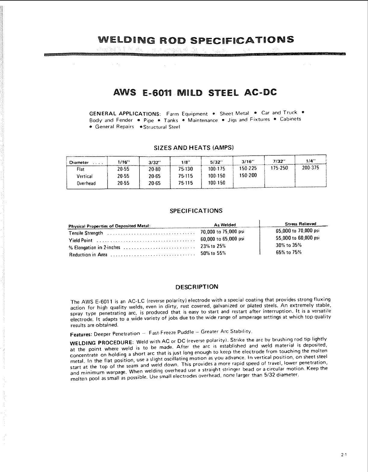
WELDING ROD SPECJF|CATiONS
AWS E-6011 MiLD STEEL AC-DC
GENERAL APPLICATIONS: Farm Equipment • Sheet Meta/ • Car and Truck •
Body and Fender ®Pipe • Tanks eMaintenance _ Jigs and Fixtures • Cabinets
e General Repairs eStructural Steel
SIZES AND HEATS lAMPS)
Diameter .... l 1/16" ._ 3/32"
Flat _ 20-55 20-80
Vertical I 20+55 ! 20.6,5
Overhead I 20-55 20-65
75-130 100+175 I 150+225 i 175-250 200-375
7,-,,5 _ 1oo.,5o i ,50.2o0 i
75.,15 l 100+150
J
J
SPECIFICATIONS
Phys!cal Pro_rties of Deposited Metal: As Welded
Tensile Strength ................................. 70,000 to 75,000 psi
YieldPoint ..................................... 60,000 to 65,000 psi
%Elongation in 2-inches ........................... 23% to 25%
Reduction in Area ................................ 50% to 55%
Stress Relieved
65,000 to 70,000 psi
55,000 to 60,000 psi
30% to 35%
65% to 75%
DESCRIPTION
The AWS E-6011 is an AC-LC (reverse polarity) electrode with a specia_ coating that provides strong fluxing
action for high quality welds, even in dirty, rust covered, galvanized or plated steels. An extremely stable,
spray type penetrating arc, is produced that is easy to start and restart after interruption. It is a versatile
electrode. |t adapts to a wide variety of jobs due to the wide range of amperage settings at which top quality
resuJts are obtained.
Features: Deeper Penetration -Fast-Freeze Puddle -- Greater Arc Stability.
WELDING PROCEDURE: Weld with AC or DC (reverse polarity). Strtke the arc by brushing rod tip lightly
at the point where weld is to be made. After the arc is established and weld mater;at is deposited,
concentrate on holding a short arc that is just long enough to keep the electrode from touching the molten
metal. In the flat position, use a slight oscillating motion as you advance, in vert+ca; position, on sheet steel
start at the top of the seam and weld down. This provides a more rapid speed of travel, lower penetration,
and minimum warpage. When we_ding overhead use a straight stringer bead or acircular motion. Keep the
molten pool .assmall as possible. Use small electrodes overhead, none larger than ,5/32 diameter.
2-1
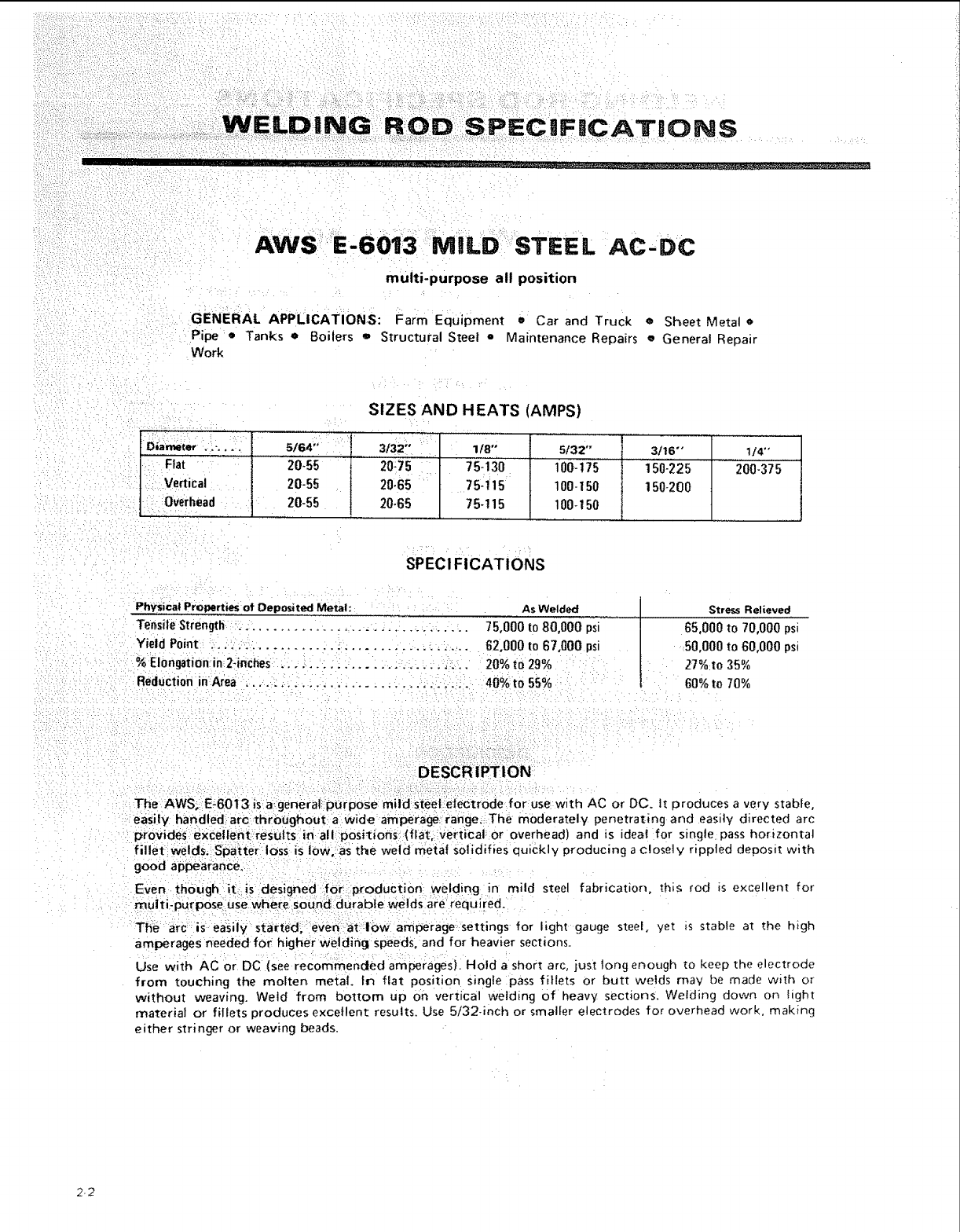
II I
AWS E-6013 MILD STEEL AC'DC
multi-purpose all position
GENERAL APPLICATIONS: Farm Equipment eCar and Truck eSheet Metal e
Pipe •Tanks • Boilers o Structural Steel = Maintenance Repairs oGeneral Repair
Work
SIZES AND HEATS (AMPS)
Diameter ._-..o,,_, 5164" ,3132" , 1/8" 5/32" 3t16"" 1/4"
Flat 20-55 20-75 75-1":3'0 100-t75 150-225 200-375
_Vertical 20-55 20-65 75-115 100-150 150-200
:: Overhead 20-55 20-65 75-115 100-150
SPECI FICATIONS
Physical Pro_erties of Deposited Metal: AsWelded
Tensile Strength _. ................................... 75,000 to 80,000 psi
Yield Point ..................................... 62,000 to 67,000 psi
% EI0ngation in 2-inc_es ............................ 20% to 29%
Reduction inArea ................................ 40% to 55%
Stress Relieved
65,000 to 70,000 psi
50,000 to 60°000 psi
27% to 35%
60% to 70%
The AWS; E:6013 is a generaLpurpoSe mild steel:elec:trode for use with AC or DC. tt produces a very stable,
easily handled arc throughout a wide amperage range,: The moderately penetrating and easily directed arc
provides eXCellent-results i_: allposi_ions_(flat_:vertical or ioverhead) and is ideal for single pass horizontal
fillet welds, s_atter loss is 10w, asthe weld metal Solidifies quickly producing a c!ose]v rippled deposit with
good appearance.
Even though it:: is designed for production welding in mild steel fabrication, this rod is excellent for
muiti-pu[pose usewhere sound durabie Welds are required.
The arc is easily started, even at:low amperage settings for light gauge steel, yet _s stable at the htgh
amperages needed for higher welding speeds, and for heavier sections.
Use with AC or DC (see recommencted amperages). Hold a short arc, just long enough [o keep the electrode
from touching the molten, metal. In fiat position single pass fillets or butt welds may be made with or
without weaving. Weld from bottom up on vertical welding of heavy sections. Welding down on hght
material or fillets produces excellent results. Use 5/32-inch or smaller electrodes for overhead work, making
either stringer or weaving beads.
2-2
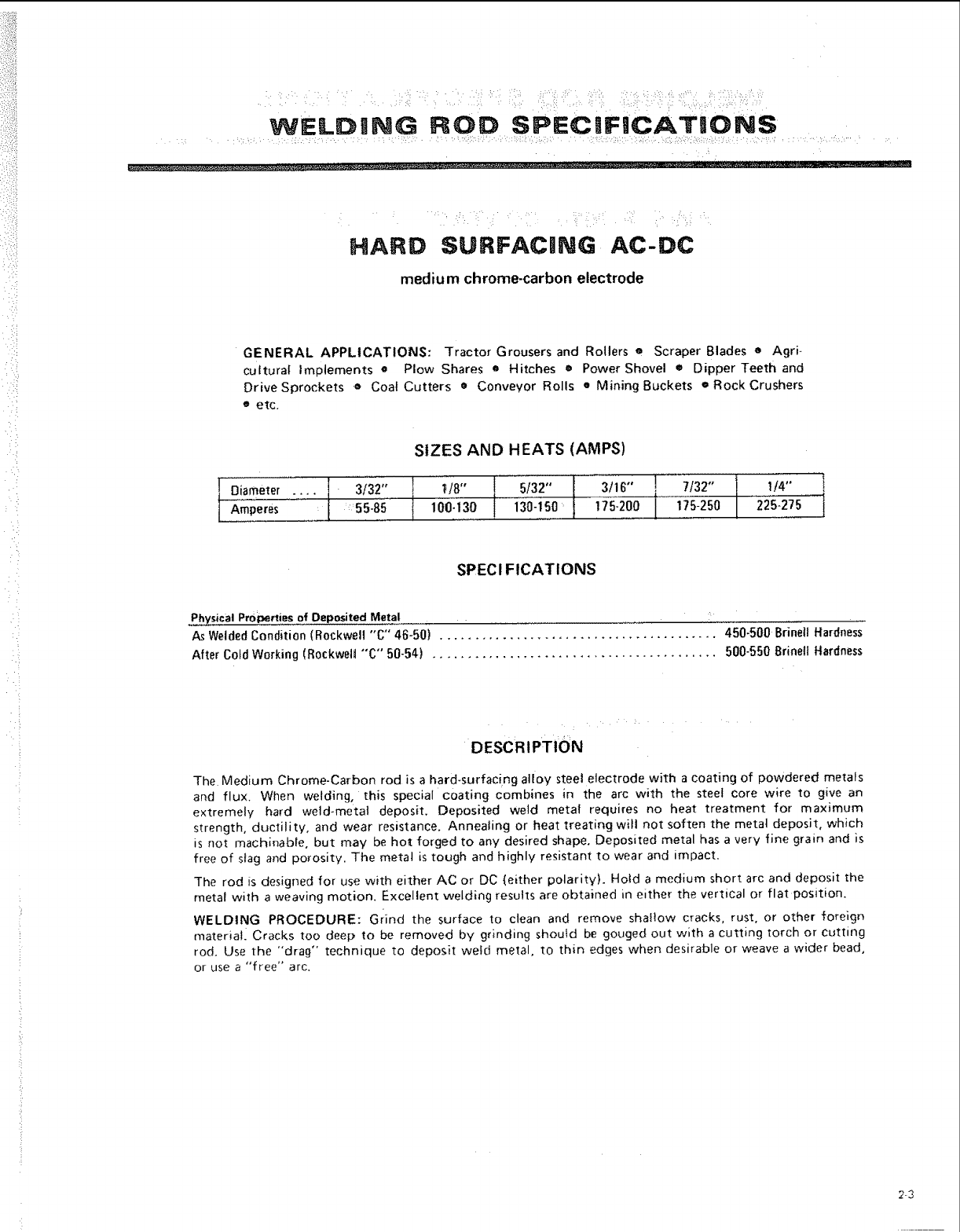
i :: :i¸ : L :¸ :: . 'i _ • _: //:: i•: I ::/•: ::•::•::i: •i¸'¸ ':_'?_ :_ _i :_•:': _:::•••:,?• _! •i•/:i•::••::: ¸'¸ :::
WELD,NG ROD SP;=CUF,CATIONS
, , ..... __ __.'---____! ......
HARD SURFACmNG AC-DC
medium chrome-carbon electrode
GENERAL APPLICATIONS: Tractor Grousers and Rollers eScraper Blades eAgri-
cultural Implements o Plow Shares o Hitches •Power Shovel • Dipper Teeth and
Drive Sprockets eCoal Cutters o Conveyor Rolls •Mining Buckets • Rock Crushers
•etc.
IDiameter
[Amperes
.... 3/32"
=55-85
SIZES AND HEATS (AMPS)
,/8" 5/32" I_ l3/l'l ',_ I} 7/32" ] 1/4'' I_
100-130 130-150_ 175-200 175-250 225-275
SPECI FICATIONS
Physical Properties of Deposited Metal ....
As Welded Condition (Rockwell "C" 46-50) ........................................ 450-500 Brinell Hardness
After Cold Working (R0ckwelt "'C" 50-54) ......................................... 500-550 Brinetl Hardness
DESCRIPTION
The Medium Chrome-Carbon rod is a hard-surfacing alloy steel electrode with a coating of powdered metals
and flux. When welding, this special coating combines in the arc with the steel core wire to give an
extremely hard weld-metal deposit. Deposited weld metal requires no heat treatment for maximum
strength, ductility, and wear resistance. Annealing or heat treating will not soften the metal deposit, which
is not machinable, but may be hoI forged to any desired shape. Deposited metal has a very fine grain and is
free of stag and porosity. The metal is tough and highly resistant to wear and impact.
The rod is designed for use with either AC or DC (either polarity). Hold a medium short arc and deposit the
metal with aweaving motion. Excellent welding results are obtained in either the vertical or flat position.
WELDING PROCEDURE: Grind the surface to clean and remove shaltow cracks, rust, or other foreign
materiatl Cracks too deep to be removed by grinding should be gouged out with a cutting torch or cutting
rod. Use the "drag" technique to deposit weld metal, to thin edges when desirable or weave a wider bead,
or use a "free" arc.
2-3
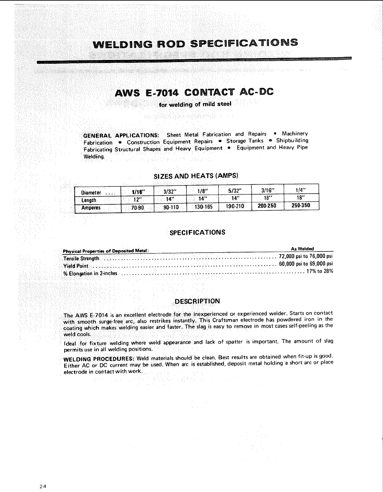
CIFICATION$
AWS E,70141CONTACT AC-DC
f0r welding of mild steel
GENERAL. APPLICATIONS: Sheet Metal Fabrication and Repairs =Machinery
Fabrication oConstruction Equipment Repairs eStorage Tanks e Shipbuilding
Fabricating Structural Shapes and Heavy Equipment e Equipment and Heavy Pipe
Welding.
SIZES AND HEATS {AMPS)
Diameter .... 1/16"
Lengtl_ ,.... 12-:
:Amperes : 70-90
3/32" 1/8"
, .... |4 i:' 14"
: 90-110 i30"165
5/32"
14"
190-210
i3/1s"
18""
200-250
I
t/4"
18"
250-350
SPEC! FICATIONS
Physical P,roperties of Deposited Metal: As Welded
TensileStrength ................................................................ 72,000 psito 76,000 psi
Yield Point . .................................................................... 60,000 psito 69,000 psi
%Elongationin 2-inches .................................................................. 17%to 28%
DESCRIPTION
The AWS E-7014: iS an excellent electrode:for:the inexperienced or experienced welder. Starts on contact
With Sm00th: Surge:free arc; als() restrikes instantly; Thls Craftsman electrode has powdered iron in the
coating wi_ich:makes welding easier and faster, :The •slag is easy to remove in most casesself-peeling as the
_td cools:.
Ideal for fixture Welding Where weld appearance and lack of spatter is important. The amount of slag
permits use in all welding positions.
WELDING PROCEDURES:Weld materials should be clean. Best results are obtained when fit-up is good.
Either AC or DC current may:be used.When arc is established, deposit metal holding a short arc or place
electrode in contact with work:
2.4
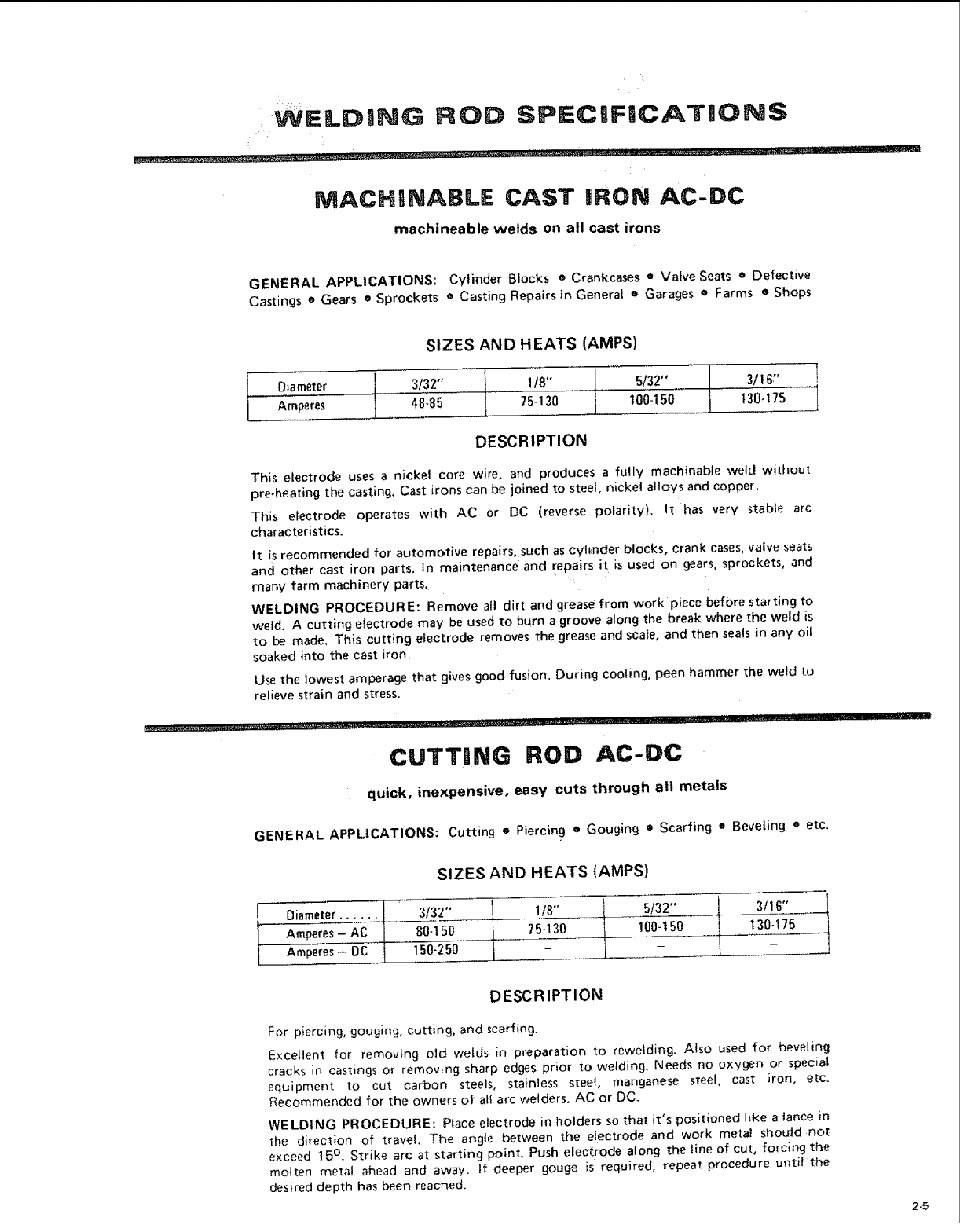
MACHINABLE CAST iRON AC-DC
rnachineable welds on all cast irons
GENERAL APPLICATIONS: Cylinder Blocks •Crankcases = Valve Seats eDefective
Castings eGears eSprockets •Casting Repairs in General eGarages eFarms eShops
SIZES AND HEATS (AMPS)
Oiameter
Amperes
I
/
t3/32" I/8"
48-85 75-130 t|
5/32" J. 3/I 6;'
I00d50 | t30-775
DESCRIPTION
This electrode uses anickel core wire, and produces a fully machinable weld without
pre-heating the casting, Cast irons can be joined to steel, nickel alloys and copper,
This electrode operates with AC or DC (reverse polarity). It has very stable arc
characteristics.
tt is recommended for automotive repairs, such as cylinder blocks, crank cases, valve seats
and other cast iron parts, In maintenance and repairs it is used on gears, sprockets, anc_
many farm machinery parts.
WELDING PROCEDURE: Remove all dirt and grease from work piece before starting to
weld. Acutting electrode may be used to burn a groove along the break where the weld is
to be made, This cutting electrode removes the grease and scale, and then seals in any oif
soaked into the cast iron.
Use the lowest amperage that gives good fusion. Durir_g cooling, peen hammer the weld to
relieve strain and stress.
......... =........... _ .... ;.--.. _.... _........ ='_.-" ,___ ......
CUTT|NG ROD AC-DC
quick, inexpensive, easy cuts through all metals
GENERAL APPLICATIONS: Cutting o Piercing • Gouging o Scarfing •Beveling o etc.
SIZES AND HEATS lAMPS)
Diameter ...... J_ 3/32" 1/8"
-A-c 80. 5o 75- 3o
i
Amperes- DC t 150-250 I -
5132"
100-t50
3t16"
t30-175
DESCRIPTION
For p;ercing, gouging, cutting, and scarfing.
Excellent for removing old welds in preparation to rewelding. Also used for beveling
cracks in castings or removing sharp edges prior to welding. Needs no oxygen or special
equipment to cut carbon steels, stainless steel, manganese steel, cast iron, etc.
Recommended for the owners of atl arc welders. AC or DC.
WE LDING PROCEDURE: Place electrode in holders so that it's positioned like a lance in
the direction of travel. The angle between the electrode and work metal should not
e×ceed 15 °. Strike arc at starting point. Push electrode along the line of cut, forcing the
molten metal ahead and away. If deeper gouge is required, repeat procedure until the
desired depth has been reached.
2-5
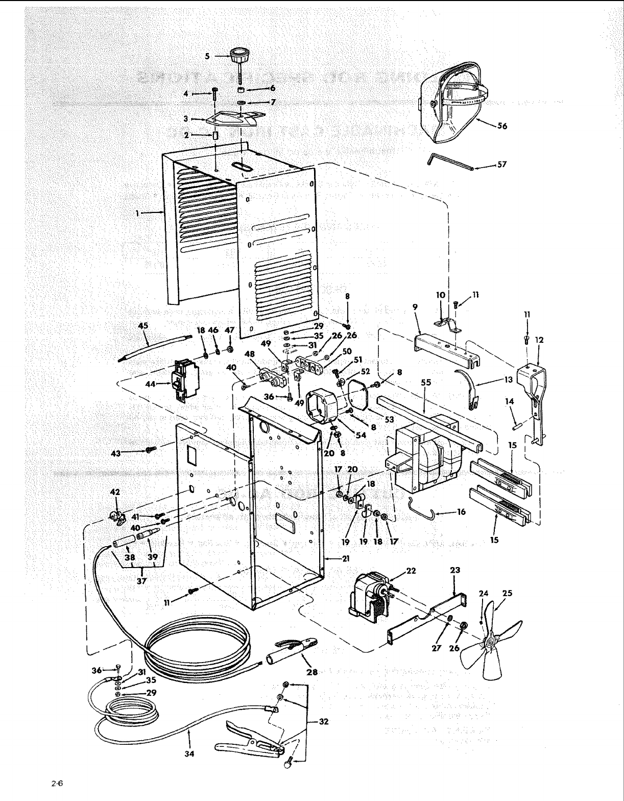
I_ 56
• _ i,,,_:_ ,_
145 :47
1
49
42
34
28 _
/•
_32
19 19 18 17
23
24 25
/
/
2_
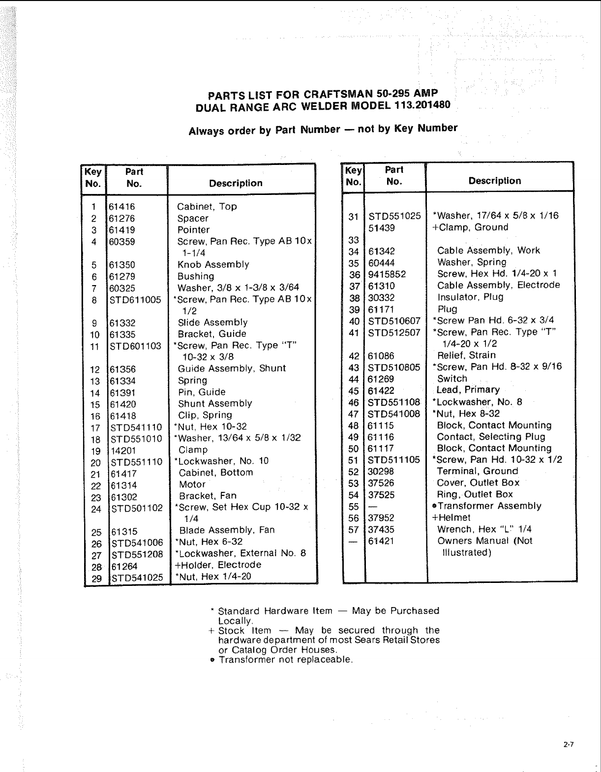
,i!
!:i
•!
PARTS LIST FOR CRAFTSMAN 50-295 AMP
DUAL RANGE ARC WELDER MODEL 113.201480
Always order by Part Number -- not by Key Number
Key Pa rt
No, No. Description
1
2
3
4
5
6
7
8
10
11
12
13
14
15
16
17
!8
19
20
21
22
23
24
25
26
27
28
29
61416
61276
61419
60359
61350
61279
60325
STD611005
61332
61335
STD601103
6! 356
61334
61391
61420
61418
STD541 ! 10
STD551010
14201
STD551110
61417
61314
61302
STD501102
61315
!STD541006
STD 5512O8
61264
STD541025
Cabinet, Top
Spacer
Pointer
Screw, Pan Rec. Type AB 10x
1-1/4
Knob Assembly
Bushing
Washer, 3/6 x 1-3/8 x 3/64
*Screw, Pan Rec. Type AB 10x
1/2
Slide Assembly
Bracket, Guide
*Screw, Pan Rec. Type "T"
10-32 x 3/8
Guide Assembly, Shunt
Spring
Pin, Guide
Shunt Assembly
Clip, Spring
*Nut, Hex 10-32
*Washer, 13/64 x 5/8 x 1/32
Clamp
*Lockwasher, No. 10
Cabinet, Bottom
Motor
Bracket, Fan
*Screw, Set Hex Cup 10-32 x
1/4
Blade Assembly, Fan
*Nut, Hex 6-32
*Lockwasher, External No. 8
+Holder, Electrode
*Nut, Hex 1/4-20
Key Part
No. No. Description
i,i
31 STD551025
51439
33
34 61342
35 60444
36 9415852
37 61310
38 30332
39 61171
40 STD510607
41 STD512507
42 61086
43 STD510805
44 61269
45 61422
46 STD551108
47 STD541008
48 61115
49 61116
50 61117
51 STD511105
52 30298
53 37526
54 37525
55
56 37952
57 37435
-- 61421
*Washer, 17/64 x 5/8 x 1/16
+Clamp, Ground
Cabie Assembly, Work
Washer, Spring
Screw, Hex Hd. 1/4-20 x 1
Cable Assembly, Electrode
Insulator, Plug
Plug
*Screw Pan Hd. 6-32 x 3/4
*Screw, Pan Rec. Type "T"
1/4-20 x 1/2
Relief, Strain
*Screw, Pan Hd. 8-32 x 9/16
Switch
Lead, Primary
*Lockwasher, No. 8
*Nut, Hex 8-32
Block, Contact Mounting
Contact, Selecting Plug
Block, Contact Mounting
*Screw, Pan Hd. 10-32 x 1/2
Terminal, Ground
Cover, Outlet Box
Ring, Outlet Box
oTransformer Assembly
+Helmet
Wrench, Hex "L'? 1/4
Owners Manuat (Not
Illustrated)
* Standard Hardware Item -- May be Purchased
Locally.
+ Stock Item -- May be secured through the
hardware department of most Sears Retail Stores
or Catalog Order Houses,
o Transformer not replaceable.
2-7
Sears
SERVICE
MODEL NO.
113o201480
HOW TO ORDER
REPAIR PARTS
50=295 AMP DUAL RANGE:
ARC WELDER
Now that you have purchased your 295 amp arc welder,
should a need ever exist for repair parts or service, simply
contact any Sears Service Center and most Sears, Roebuck
and Co. stores. Be sure to provide afl pertinent facts when
you call or visit.
The model number of your arc welder will be found on a
plate attached to your welder, at the rear of the cabinet.
WHEN ORDERING REPAIR PARTS, ALWAYS GIVE THE
FOLLOWING INFORMATION:
PART NUMBER PART DESCRIPTION
MODEL NUMBER
113.201480
NAME OF ITEM
50-295 AMP ARC WELDER
All parts listed may be ordered from any Sears Service
Center and most Sears stores. If the parts you need are not
stocked locally, your order will be etectronicaIfy
transmitted to a Sears Repair Parts Distribution Center for
handling,
Sold by SEARS, ROEBUCK AND CO., Chicago, IL 60684 U.S.A.
Part No. 61421 Form No. SP4654-2 Printed in U.S.A. 7/84
