Craftsman 113213130 User Manual 13 DRILL PRESS Manuals And Guides L0803275
CRAFTSMAN Drill Press Manual L0803275 CRAFTSMAN Drill Press Owner's Manual, CRAFTSMAN Drill Press installation guides
User Manual: Craftsman 113213130 113213130 CRAFTSMAN CRAFTSMAN 13 DRILL PRESS - Manuals and Guides View the owners manual for your CRAFTSMAN CRAFTSMAN 13 DRILL PRESS #113213130. Home:Tool Parts:Craftsman Parts:Craftsman CRAFTSMAN 13 DRILL PRESS Manual
Open the PDF directly: View PDF ![]() .
.
Page Count: 32
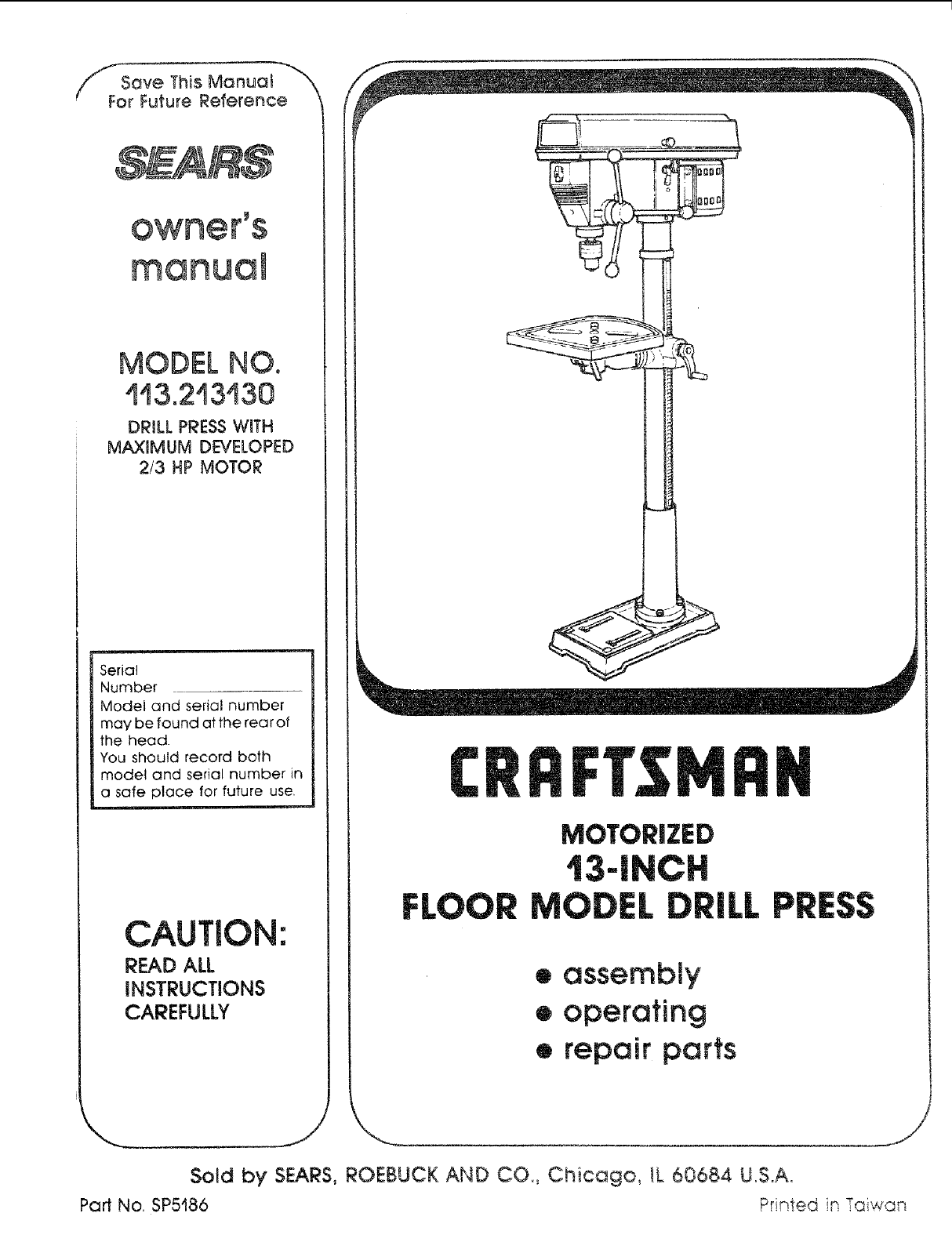
//_ Save This Manual "_
For Future Reference
MODEL NO.
'_!3.2'13!30
DRILL PRESS WITH
MAXIMUM DD!ELOPED
2/3 HP MOTOR
Serial
Number
Model and serial number
may be found at the rear of
the head.
You should record both
model and serial number in
a safe place for future use,
l lll
CAUTION:
READ ALL
iNSTRUCTIONS
CAREFULLY
MOTORIZED
IEL
eassembly
eoperating
•repair parts
,L Pl
x,..
Sold by SEARS, ROEBUCK AND CO., Chicago, tL 60684 U.S.A.
Part No. SP5186 Printed in ÷_;, _"_,_
FULL ONE YEAR WARRANTY ON CRAFTSMAN DRILL PRESS
If within one year from the date of purchase, this Craftsman Drill Press fails due to a defect
in material or workmanship, Sears will repair it, free of charge.
WARRANTY SERVICE IS AVAILABLE BY SIMPLY CONTACTING THE NEAREST SEARS SER-
ViCE CENTER!DEPARTMENT THROUGHOUT THE UNITED STATES.
This warranty applies only while this product is used in the United States.
This warranty gives you specific legal rights, and you may also have other rights which
vary from state to state.
SEARS, ROEBUCK AND CO., Dept. 698/73tA, Sears Tower, Chicago, IL 60684
GENERAL SAFETY INSTRUCTmONS FOR POWER TOOLS
1. KNOW YOUR POWER TOOL
Read and understand the owner's manual and
labels affixed to the tool, Learn its application and
fimkations as welt as the specific potential hazards
pecuiiar to th{s tool,
2. GROUND ALL TOOLS
Thistoolisequippedwithan approved3-conductor
cord and a 3-prong grounding tyoe pIug to fit the
proper grounding type receptacle, The green con-
ductor in the cord is the groundin 9 wire Never
connect the green wire to a live terminal.
3. KEEP GUARDS IN PLACE
in working order, and in proper adjustment and
alignment.
4. REMOVE ADJUSTING KEYS AND WRENCHES
Form a habit of checking to see that keys and
adjusting wrenches are removed from tool before
turning it on.
5. KEEP WORK AREA CLEAN
Cluttered areas and benches invite accidents. Floor
must not be slippery due to wax or sawdust,
6. AVOID DANGEROUS ENVIRONMENT
Don't use power tools in damp or wet locations or
expose them to rain. Keep work area well lighted.
Provi(_e adequate surrounding work space.
7. KEEP CHILDREN AWAY
A_t visitors should be kept a safe distance from
work area.
8. MAKE WORKSHOP CHILD-PROOF
With padlocks, master switches, by removing star-
ter keys, or storing tools where children can't get
them,
9. DON'T FORCE TOOL
It will do the job better and safer at the rate for
which it was designed,
10. USE RIGHTTOOL
Don_tforce tools or attachment to do a job it w&s
not designed for,
11. WEAR PROPER APPAREL
Do not wear loose clothing, gloves, neckties, or
jewelry (rings, wrist watches) to get caught in mov-
ing parts. NONSLtP footwear is recommended.
Wear protective hair covering to contain long hair.
Rolt long sleeves above the elbow.
12. USE SAFETY GOGGLES (HEAD PROTECTION)
Wear safety goggles (must comply with ANSI
Z87.1) at al! times. Everyday eyeglasses are not
safety glasses, They only have impact resistant
ienses. Also, use face or dust mask if cutting oper-
ation is dusty, and ear protectors (plugs or muffs)
during extended periods of operation.
13. SECURE WORK
Use clamps or a vise to hold work when practical
It frees both hands to operate tool.
14. DON"I" OVERREACH
Keep proper foobng and balance at aft times,
15. MAINTAIN TOOLS WiTH CARE
Keep tools sharp and clean for best and safest
performance. Follow instructions for lubricating and
changing accessories.
16. DISCONNECT TOOLS
Before servicing;when changing accessories such
as blades, bits, cutters, etc.
17. AVOID ACCIDENTAL STARTING
Make sure switch is in "OFF" position before plug-
ging in.
18. USE RECOMMENDED ACCESSORIES
Consult the owner's manual for recommended ac-
cessories. Follow the instructions that accompany
the accessories, The use of improper accessories
may cause hazards.
19. NEVER STAND ON TOOL OR ITS STAND
Serious injury could occur if the tool is tipped or if
the cutting tool is accidentally contacted. Do not
store rnatenais above or near the tool such that it
is necessary to stand on the tool or its stand to
reach them.
20. CHECK DAMAGED PARTS
Before further use of the too!, a guard or other part
that is damaged should be carefully checked to
ensure that it will operate properly and perform its
_ntended function, Check for alignment of moving
parts, binding or moving parts, breakage of parts,
mounting, and any other conditions that may affect
its operation. A guard or other part that is damaged
should be properly repaired or replaced.
21. DIRECTION OF FEED
Feed work into a blade or cutter against the direc-
tion of rotation of the blade or cutter only.
22. NEVER LEAVETOOL RUNNING UNATTENDED
Turn power off Don't teave too! until it comes to a
complete stop.
additional safety instructions for drill presses
WARNING: FOR YOUR OWN SAFETY, DO NOT
USE YOUR DRILL PRESS UNTIL mT IS COM-
PLETELY ASSEMBLED AND INSTALLED ACCORD-
ING TO THE INSTRUCTIONS... AND UNTIL YOU
HAVE READ AND UNDERSTAND THE FOLLOW-
iNG:
1. General Safety Instructions for Power Tools. 2
2. Getting to Know Your Drill Press ........ 17
3. Basic Drill Press Operation ............. 22
4. Adjustments .......................... 24
5. Maintenance .......................... 25
6. Stability of Drill Press
If there is any tendency of the drill press to tilt or
move during any use, bolt it to the floor or a flat
piece of W" exterior plywood large enough to
stabilize the drill press. Bolt the plywood to the
underside of the Base, so it extends at least to
both sides, Make sure the plywood won't trip the
operator. Do not use pressed wood panels
they can break unexpectedly.
If the workpiece is too large to easily support with
one hand, provide an auxiliary support.
7. Location
Use the drill press in a well tit area and on a leve!
surface clean and smooth enough to reduce the
risk of trips, slips, or faIts, Use it where neither the
operator nor a casual observer is forced to stand
in line with a potential kickback.
8. Kickback
A kickback occurs when the workpiece is suddenly
thrown in the OPPOSITE direction to the DIREC-
TION OF FEED: THIS CAN CAUSE SERIOUS IN-
JURY. Kickbacks are most commonly caused by
use of accessories NOT recommended for this tool,
9. Protection: Eyes, Hands, Face, Earsand Body
WARNING: TO AVOID BEING PULLED INTO
THE SPINNING TOOL --
1. Do NOT wear:
-- gloves
necktie
-- loose clothing
-- jewelry
2. Do tie back long hair
a. If any partofyourdrill press _smissing, malfunc-
tioning, has been damaged or broken.., such
as the motor switch, or other operating control
a safety device or the 0ower cord . cease
operating immediately until the particular part
is properly repaired or replaced.
b. Never place your fingers in a position where
they could contact the drill or other cutting tool
if the workpiece should unexpectedly shift or
your hand should slip,
c. To avoid injury from parts thrown by the spring,
follow instructions exactly as given and shown
in adjusting spring tension of quill.
d. To prevent the workpiece from being
torn from your hands, spinning of the
tool, shattering the too/or being thrown,
always properly support your work so
it won't shift or bind on the toot:
-- Always position BACKUP MATERIAL (use
beneath the workpiece) to contact the left
side of the column.
-- Whenever possible, position the WORK-
PIECE to contact the left side of the col-
umn-if it is too short or the table is tilted,
clamp solidly to the table. Use table slots
or clamping ledge around the outside edge
of the table.
-- When using a drill press VICE, always fas-
ten it to the table.
-- Never do any work "FREEHAND" (hand-
holding workpiece rather than supporting it
on the table), except when polishing.
-- Securely lock Head and Support to Column,
Table Arm to support, and Table to Table
Arm before operating drill press.
-- Never move the Head or Table while the
tool is running.
-- Before starting the operation, jog the motor
switch to make sure the drill or other cutting
toot does not wobble or cause vibration.
-- If a workpiece overhangs the table such
that it will fall or tip if not held, clamp it to
the table or provide auxihary support.
-- Use fixtures for unusual operations to
adequately hold, guide and position work-
piece.
-- Use the SPINDLE SPEED recommended
for the specific operation and workpiece
material--check the label inside the Belt
Guard for drilling information; for acces-
sories, refer to the instructions p_ovided
with the accessories.
f. Never climb on the drill press Table, it
could break or pull the entire drill press
down on you.
g. Turn the motor Switch Off and put away
the Switch Key when leaving the drilt
press.
h To avoid injury from thrown work or tool
contact, do NOT perform layout, as-
sembly, or setup work on the table wNe
the cutting tool is rotating.
10. Use only accessories designed for this
drill press to avoid serious injury from
thrown broken parts or work pieces,
a Holesaws must NEVER be operated on
this drill press at a speed greater than
400 RPM.
_:_ Dum NEVER be operated on
ths dd pi'e_ at a _ed g_eater than t800
RPM
c Do _ot inStait o_ ,,,_seany driP!that exceeds 7" in
engt_ 0 e×te_tds 6!t'below the Chuck aws. They
car_ S_dden_y be_d outward o_ break,
d Do not Use Wire wheets, _outer bits shaper cut-
ters circle ffly}: cutters Or rotary ptaners on this
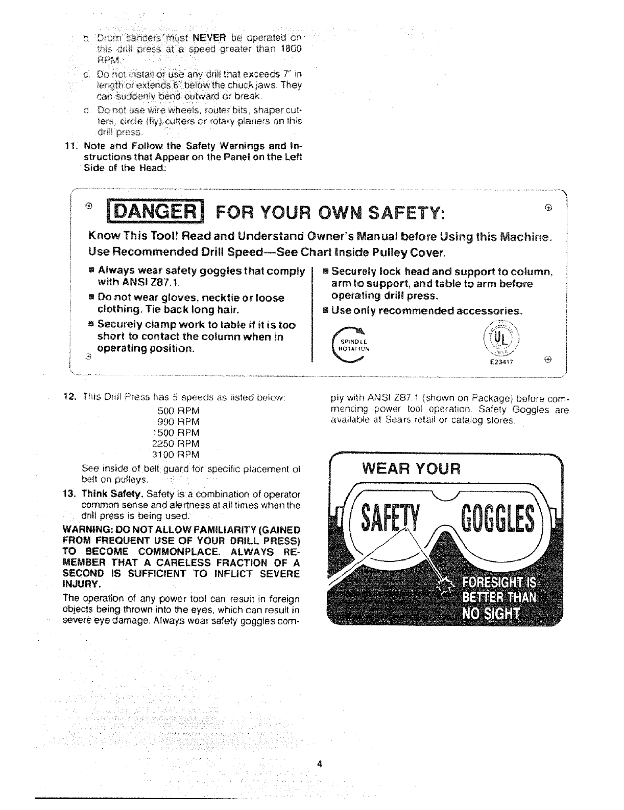
1!_ Note and Follow the Safety Warnings and In-
structions that Appear on the Panell on the Left
Side of the Head:
FOR YOUR OWN SAFETY:
Know This Toot! Read and Understand Owner's _anuai before Using this Machine.
Use Recommended Drill Speed_See Chart inside Puitey Cover.
=Always wear safety goggles that comply
with ANSI Z87,1.
mDo not wear gloves, necktie or loose
clothing, Tie back long hair.
m Securely clamp work to table if it is too
short to contact the column when in
operating position.
aSecurely took head and support to column,
arm to support, and table to arm before
operating drill press.
m Use only recommended accessories.
12, Th_s Dd_t Press has 5 speeds as hsted below:
500 RPM
990 RPM
1500 RPM
2250 RPM
3100 RPM
See inside of belt guard for specific p_acernent of
beit on puiteys
t3. Think Safety. Safety is a combination of operator
common sense and alertness at all times when the
dr_li press is being used.
WARNING: DO NOT ALLOW FAMILIARITY (GAINED
FROM FREQUENT USE OF YOUR DRILL PRESS)
TO BECOME COMMONPLACE. ALWAYS RE-
MEMBER THAT A CARELESS FRACTION OF A
SECOND tS SUFFICIENT TO INFLICT SEVERE
INJURY.
The operation of any power tool can result in foreign
objects being thrown into the eyes. which can result Rn
severe eye damage. Always wear safety goggles corn-
p!y with AK_S! Z87 1 (shown on Package) before corn-
rnencing power tool operation. Safety Goggles are
avai!able at Sears retail or catatog stores.
gaossary of terms
1. Workpiece
The item or_ which the cutti_'_g operations is being
performed.
2. Drill
The cutting tool used in the drii_ press to make hotes
in a workpiece.
3. Backup Material
A piece of wood placed between the workpiece and
table .... it prevents wood in the workpiece from
splintering when the dril! passes through the back--
side of the workpiece .... also prevents drilling into
the table top
4. Revolution Per Minute (R.P.M.)
]he number of turns ,,:ompleled by a sp_nn_ng object
in one minute
5. Spindle Speed
The RPM of the spindie.
table of
Page
General Safety Instructions for Power Toots ...... 2
Additional Safety Instructions for Drill Presses .... 3
Glossary of Terms .......................... 5
Table of Contents .......................... 5
Motor Specifications and Electrical
Requirements .............................. 6
Unpacking and Checking Contents ............. 7
Table of Loose Parts ........................ 8
Location and Function of Controls ............. 9
Assembly ................................ 10
Assembly of Column and Table Hardware... 10
Installing the Table ..................... 11
Installing the Head .................... 11
Mounting Motor ........................ 12
Installing Motor Pulley ................... 12
Tensioning Belt ........................ 12
Installing Belt Guard Knob ............... 13
Motor Connections ..................... t 4
Installing Feed Handles ................. 14
Installing the Chuck ..................... 14
contents
Page
Adjusting the Table Square to Head ....... 16
Bevel Scale .......................... ! 6
Getting to Know Your Drill Press .............. 17
On-Off Switch ......................... I g
Drilling to a Specific Depth ............... 20
Locking Chuck Desired Depth ............ 20
Removing Chuck ...................... 21
Basic Drill Press Operation .................. 22
Installing Drills ......................... 22
Positioning Table and Workpiece ......... 23
Tilting Table ........................... 24
Hole Location ........................ 24
Feeding ............................. 24
Adjustments .............................. 24
Quill Return Spring ................... 24
Maintenance .............................. 25
Lubrication .............................. 25
Recommended Accessories .................. 25
Troubie Shooting .......................... 26
Repair Parts .............................. 27
motor specifications electrical
i,
MOTOR SPECiFICATiONS
ThiS drili press is designed to use a 1725 RPM motor
only. Do not use any motor that runs faster than t725
RPM, It is wired for operation on 1t 0-120 volts, 60 Hz.
alternating current.
WARNING: TO AVOID INJURY FROM UNEX-
PECTED STARTUP, DO NOT USE BLOWER OR
WASHING MACHINE MOTORS OR ANY MOTOR
WiTH AN AUTOMATIC RESET OVERLOAD PRO-
TECTOR.
CONNECTING TO POWER
SOURCE OUTLET
This machine must be grounded while in use to protect
the operator from electric shock,
Plug power cord into a 110-120V properly grounded
type outlet protected by a 15-amp dual element time
deiay or Circuit breaker.
NOT ALL OUTLETS ARE PROPERLY GROUNDED.
IF YOU ARE NOT SURE THAT YOUR OUTLET, AS
PICTURED BELOW, IS PROPERLY GROUNDED,
HAVE IT CHECKED BY A QUAUFIED ELECTRICIAN.
WARNING: TO AVOID ELECTRIC SHOCK, DO NOT
TOUCH THE METAL PRONGS ON THE PLUG,
WHEN iNSTALLING OR REMOVING THE PLUG TO
OR FROM THE OUTLET.
WARNING: FAILURETO PROPERLY GROUNDTHIS
POWER TOOL CAN CAUSE ELECTRICUTION OR
SERIOUS SHOCK. PARTICULARLY WHEN USED IN
DAMP LOCATIONS. OR NEAR METAL PLUMBING.
IF SHOCKED, YOUR REACTION COULD CAUSE
YOUR HANDS TO HIT THE CUTTING TOOL.
IF POWER CORD IS WORN OR CUT, OR DAMAGED
IN ANY WAY, HAVE IT REPLACED IMMEDIATELY
TO AVOID SHOCK OR FIRE HAZARD.
3*PRONG
PLUG
'\
GROUNDING
PRONG
requirements
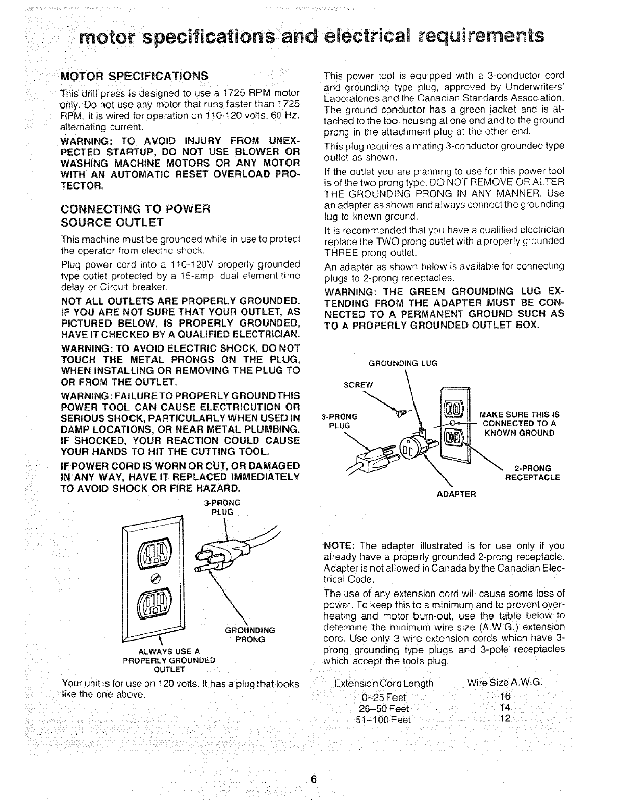
This power tool is equipped with a 3-conductor cord
and grounding type plug, approved by Underwriters'
Laboratories and the Canadian Standards Association.
The ground conductor has a green jacket and is at-
tached to the tool housing at one end and to the ground
prong in the attachment plug at the other end.
This plug requires a mating 3-conductor grounded type
outlet as shown.
If the outlet you are planning to use for this power tool
is of the two prong type, DO NOT REMOVE OR ALTER
THE GROUNDING PRONG IN ANY MANNER. Use
an adapter as shown and always connect the grounding
lug to known ground.
It is recommended that you have a qualified electrician
replace the TWO prong outlet with a properly grounded
THREE prong outlet.
An adapter as shown below is available for connecting
plugs to 2-prong receptacles,
WARNING: THE GREEN GROUNDING LUG EX-
TENDING FROM THE ADAPTER MUST BE CON-
NECTED TO A PERMANENT GROUND SUCH AS
TO APROPERLY GROUNDED OUTLET BOX.
GROUNDING LUG
SCREW \
//'_ ", X 2*PRONG
XRECEPTACLE
ADAPTER
NOTE: The adapter illustrated is for use only if you
already have a properly grounded 2-prong receptacle.
Adapter is not allowed in Canada bythe Canadian Elec-
trical Code.
The use of any extension cord will cause some loss of
3ower. To keep this to a mmrmum and to prevent over-
qeating ano motor burn-out, use the table below to
determine the minimum wire s=ze (A.W.G.) extension
cora, Use only 3 wire extension cords which have 3-
prong grounding type plugs and 3-pole receptacles
which accept the tools p_ug.
ALWAYS USE A
PROPERLY GROUNDED
OUTLET
Your unit is for use on 120 volts. It has a plug that looks ...................
like the one above. 0-25 Feet
26-50 Feet
51-100 Feet
Wire Size A.W.G.
16
14
t2

unpacking and checking contents
WARNING: TO AVOID iNJURY FROM UNEX-
PECTED STARTING OR ELECTRICAL SHOCK, DO
NOT PLUG THE POWER CORD INTO A SOURCE
OF POWER. THIS CORD MUST REMAIN UNPLUG-
GED WHENEVER YOU ARE WORKING ON THE
DRILL PRESS.
Mode! 113.213130 Drift Press is shipped complete in
one box.
1. Unpacking and Checking Contents
a. Separate all "loose parts" from packaging mate-
rials and check each item with "Table of Loose
Parts" to make sure all items are accounted for.
before discarding any packing material. Some
loose parts are contained inside the belt guard.
Open the belt guard cover to find them,
WARNING: _F ANY PARTS ARE MKSSING, DO NOT
ATTEMPT TO ASSEMBLE DRILL PRESS, PLUG iN
THE POWER CORD, OR TURN THE SW_TCH ON
UNTIL THE MiSSiNG PARTS ARE OBTAINED AND
ARE INSTALLED CORRECTLY.
2. Remove the protective oil that is applied to the
table and column. Use any ordinary household type
grease and spot remover,
WARNING: TO AVOID FiRE OR TO×mC REAC-
TION, NEVER USE GASOLINE, NAPTHA OR
SIMILAR HIGHLY VOLATILE SOLVENTS.
3. Apply a coat of paste wax to the table and column
to prevent rust, Wipe at1parts thoroughly with a clean
dry cloth.
TABLE OF LOOSE PARTS
item Description
A Tab!e
B Column SUppori Asm.
c Owner s Manual .
D Motor .......
E Bag of Loose Parts
F Base ......
G Head Asm. ..
H Box of Loose Parts
H\
2
i
!
F
/
E
BC
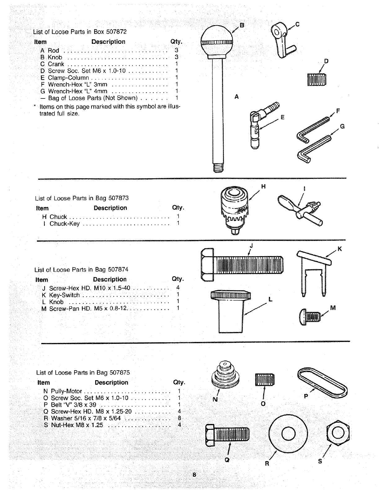
List of Loose Parts in Box 507872 /_'_/' _/
,tern Description Qty. _LU_ \ I1_'
Rod...................... 3 \ J I11
B Knob .................. 3 "_ --:f _ _
C Crank .............................. 1 /_
D Screw Soc. Set M6 x 1.0-10 ............ 1 /
E Clamp-Column,,. ...................... 1 _]_
F Wrench-Hex"L 3mm ................. 1
G Wrench-Hex "L" 4mm ................. 1
-- Bag of Loose Parts (Not Shown) ...... 1 A
* Items on this page marked with this symbol are illus-
trated full size. _E ._/F
List of Loose Parts in Bag 507873
item Description Qty.
H Chuck ............................. t
Chuck-Key .......................... 1
H I
List of Loose Parts in Bag 507874
Item Description Qty.
J Screw-Hex HD. M10 x !.5-40 ........... 4
K Key-Switch .......................... I
L Knob .............................. 1
M Screw-Pan HD. M5 x 0.8-12 ............. 1
J
1
List of Loose Parts in Bag 507875
Item Description Qty.
N Pully-Motor .......................... 1 /
O Screw Soc. Set M6 x 1.0-10 ............ 1
P Belt "V" 3/8 x 39 .................... 1
O Screw-Hex HD. M8 x 1.25-20 ........... 4
R Washer 5/16 x 7/8 × 5/64 .............. 8
S Nut-Hex M8 x 1.25 ................... 4 l,l,Il!,BI,I,
O
÷
0
/
/" /
R S
8
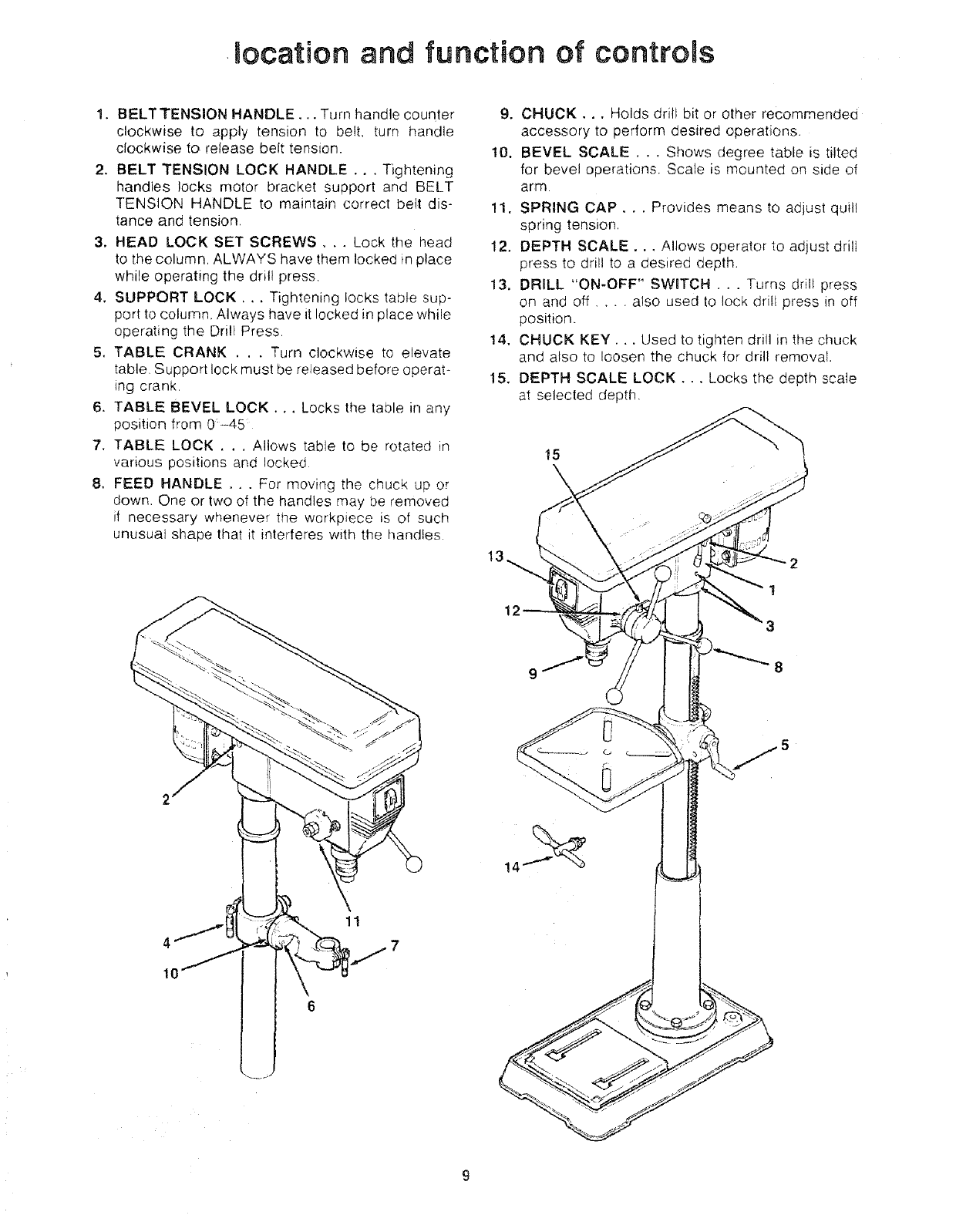
mecation and functien ef centrols
1. BELTTENSION HANDLE..• Turn handle counter
clockwise to apply tension to belt. turn handle
clockwise to release belt tension,
2. BELT TENSION LOCK HANDLE... Tightening
handles locks motor bracket support and BELT
TENSION HANDLE to maintain correct bett dis-
tance and tension
3. HEAD LOCK SET SCREWS... Lock the head
to the column, ALWAYS have them locked in place
while operating the drill press
4. SUPPORT LOCK •.. Tightening locks table sup-
port to column, Always have it locked in place while
operating the Drill Press
5. TABLE CRANK . , . Turn clockwise to elevate
table Support lock must be released before operat-
ing crank.
6. TABLE BEVEL LOCK.., Locks the table in any
position from 0-45
7. TABLE LOCK . . , Allows table to be rotated in
various positions and locked
8. FEED HANDLE . . . For moving the chuck up or
down One or two of the handles may be removed
if necessary whenever the workpiece is of such
unusual shape that it interferes with the handles
4
10
11
9. CHUCK.., Holds drill bit or other recommended
accessory to perform desired operations.
10. BEVEL SCALE, . . Shows degree table is tilted
for bevel operations. Scale is mounted on side of
arm
11. SPRING CAP, ..Provides means to adjust quill
spring tension,
12. DEPTH SCALE... Allows operator to adjust drill
press to drill to a desired depth.
13. DRILL "ON-OFF" SWBTCH .. . Turns drill press
on and off .... also used to lock drill press in off
position.
14, CHUCK KEY... Used to tighten drill in the chuck
and also to loosen the chuck for drill removal.
15. DEPTH SCALE LOCK.,. Locks the depth scale
at selected depth,
15
12
1
3
8
assembgy
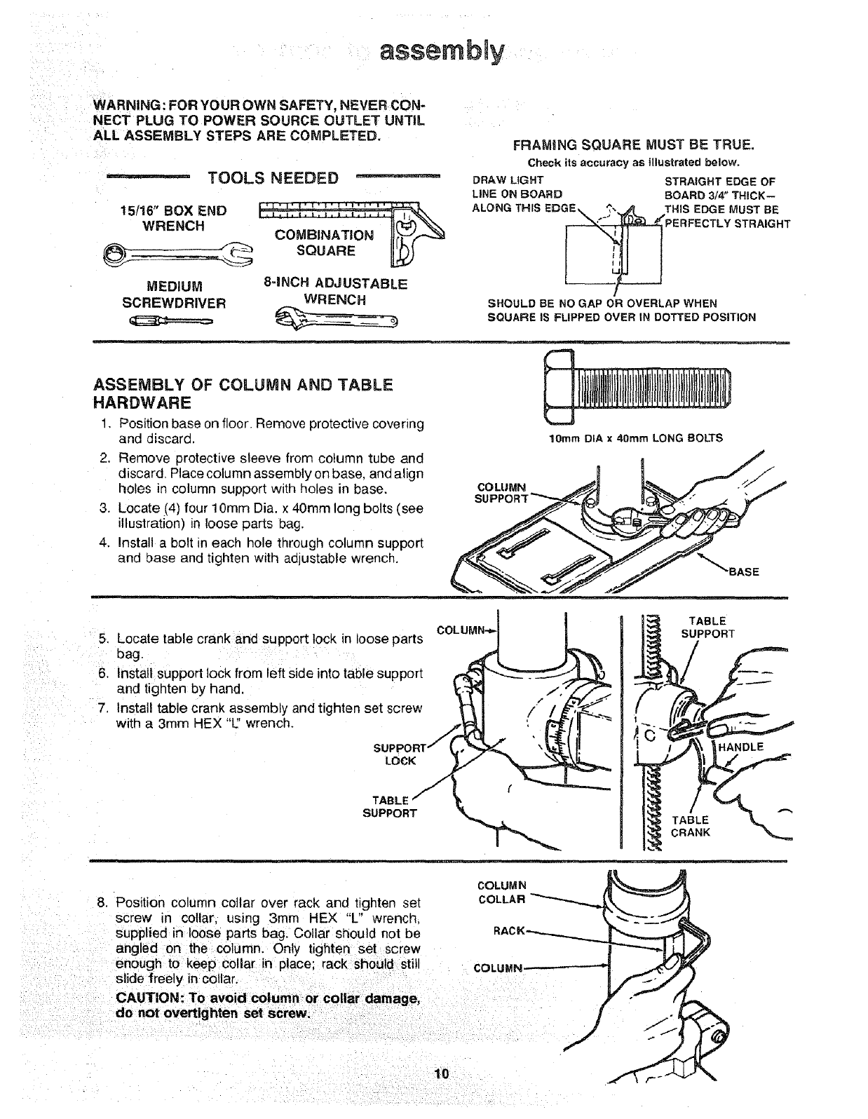
WARNING :FOR YOUR OWN SAFETY, NEVER CON"
NECT PLUG TO POWER SOURCE OUTLET UNTIL
ALL ASSEMBLY STEPS ARE COMPLETED.
TOOLS NEEDED
15/16" BOX END
WRENCH
MEDIUM
SCREWDRIVER
COMBINATION I[(_(.._
SQUARE [L_
8-INCH ADJUSTABLE
WRENCH
FRAMING SQUARE MUST BE TRUE.
Check its accuracy as Illustrated belowo
DRAW LIGHT STRAIGHT EDGE OF
LiNE ON BOARD BOARD 3/4" THICK--
SHOULD BE NO GAP OR OVERLAP WHEN
SQUARE IS FLIPPED OVER iN DOTTED POSiTiON
ASSEMBLY OF COLUMN AND TABLE
HARDWARE
1, Position base on floor. Remove protective covering
and discard.
2. Remove protective sleeve from column tube and
discard. Place column assembly on base. one align
holes in column support with holes in base.
3. Locate (4) four 10turn Dia. x 40mrn long bolts (see
illustration) in loose parts bag.
4. Install a bolt in each hole through column support
and base and tighten with aojustable wrench.
COLUMN
10mm DIA x 40ram LONG BOLTS
_'_BASE
.
6.
7.
m__
Locate table crank and support lock in loose arts COLLIMN"_I !
bag P J!P
Install support lock from left side into table support _ _ ._'-_'F__J._L
and tighten by hand _-."3_ ..-"/f
I''" " _'_
nstal, table crank assembly and t,ghten set screw "_ 1 /" "/_
witha 3mmHEX"L:'wrench. TJr_y (' _fr "-_'_,.._..,.._ \_L,.,qi'
TABLE
SUPPORT
TABLE
CRANK
COLUMN
8. Position column collar over rack and tignteP set COLLAR
screw in collar, using 3mm HEX "L" wrench.
supplied in loose parts bag, Collar should not be
angled on the column. Only tighten set screw
enough to keep collar in place: rack should still COLUMN
slide freely in collar.
CAUTION: To avoid column or collar damage,
do not overtlghten set screw.
HANDLE
10
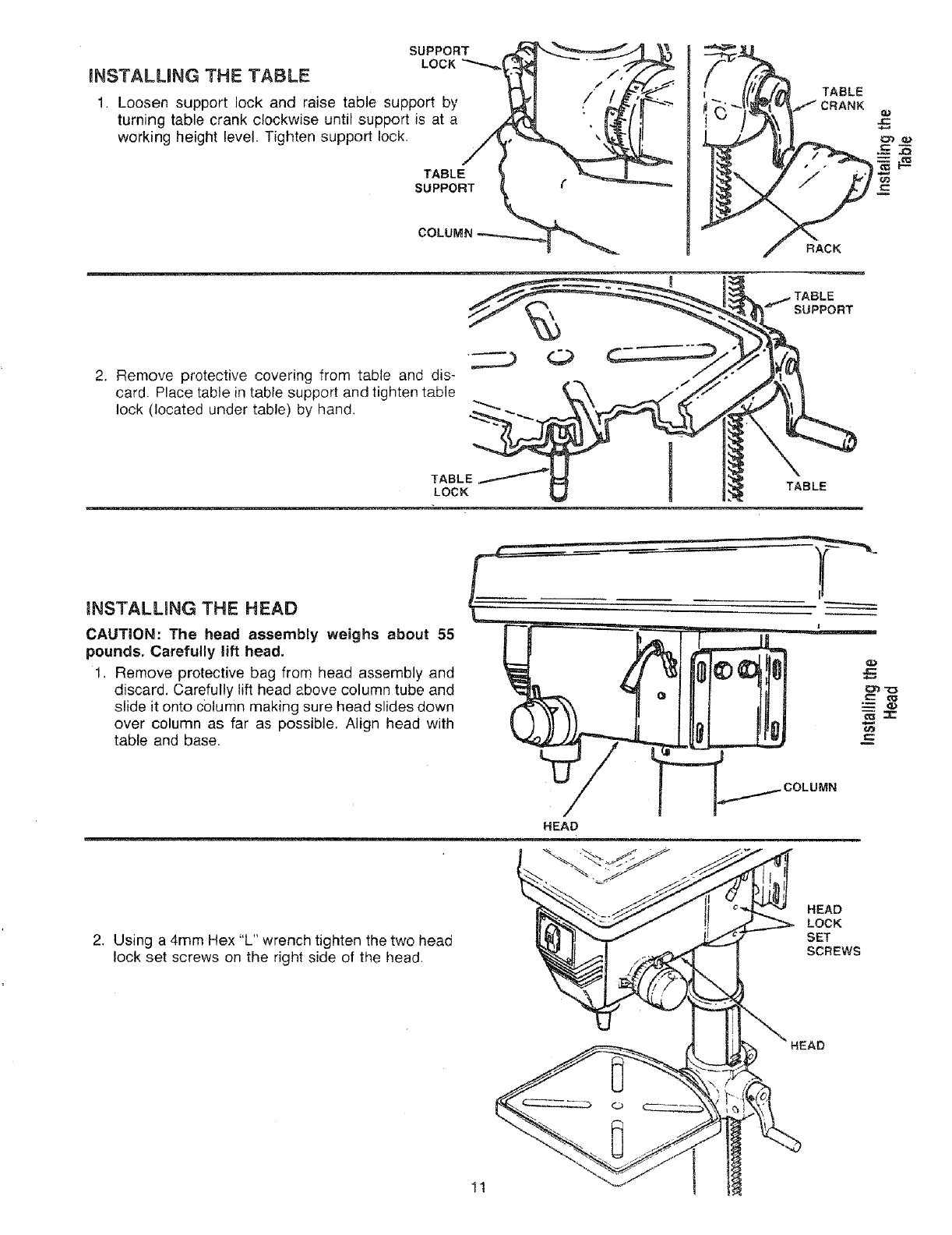
iNSTALLiNG THE TABLE
SUPPORT
LOCK
1. Loosen support lock and raise table support by
turning table crank clockwise until support is at a
working height level. Tighten support lock.
TABLE
SUPPORT f
TABLE
RACK
2. Remove protective covering from table and dis-
card. Place table in table support and tighten table
lock (located under table) by hand.
TABLE_
LOCK
m
TABLE
INSTALLmNG THE HEAD
CAUTION: The head assembly weighs about 55
pounds. Carefully lift head.
1. Remove protective bag from head assembly and
discard. Carefully lift head above column tube and
slide it onto column making sure head slides down
over column as far as possible. Align head with
table and base.
HEAD
2. Using a 4mm Hex "L" wrench tighten the two head
lock set screws on the right side of the head.
HEAD
LOCK
SET
SCREWS
HEAD
1t !
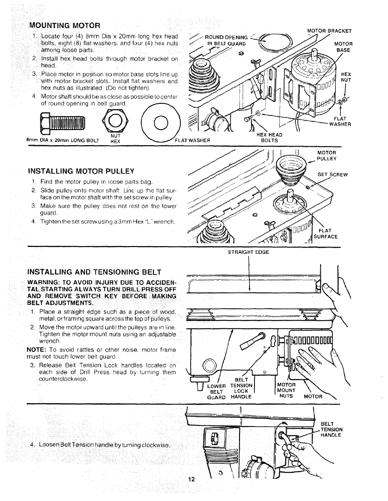
MOUNTING MOTOR
1. Locate four (4) 8turn Dig × 20mrn long hex head
bolts, eight (8) flat washers, and four (4) nex nuts
among loose parts.
2. Install hex head bolls through motor bracket on
head,
3. Place motor in position so motor base slots hne up
with motor bracket slots. Install flat washers ane
inex nuts as illustrated (Do not tighten1
4. Motor shaft should be as close as 3ossible to center
of round opening _n belt guard
NUT
8mm DIA x 20mrn LONG BOLT HEX
S J ROUND OPENING
IN BELT GUARD
_FLAT WASHER HEX HEAD
BOLTS
iNSTALLING MOTOR PULLEY
Find the motor pulley m _oose carts oag.
2. Slide pulley onto motor shaft Line UD the flat sur-
face on the motor shaft w_th the setscrew _npulley
3 Make sure the pulley goes not rest on the lower
guara
4 Tighten theset screwus=ng a3mmHex "Lwrench
STRAIGHT EDGE
MOTOR BRACKET
MOTOR
BASE
/
HEX
NUT
1
f
FLAT
WASHER
MOTOR
PULLEY
SET SCREW
FLAT
SURFACE
INSTALLING AND TENSIONING BELT
WARNING: TO AVOID INJURY DUE TO ACCIDEN- ,_--_
TAL STARTING ALWAYS TURN DRILL PRESS OFF /i
AND REMOVE SWITCH KEY BEFORE MAKING
BELT ADJUSTMENTS.
1 Place astratght edge such as a piece of wood,
metal, or framinc sc uare across the top of pulleys. _
2. Move the motor uoward until the owteys are in line.
Tighten the motor mount nuts using an adjustable
wrench.
NOTE: To avo,a rattles or other norse motor frame
must not toucD lower belt guard
3. Release Belt Tension Lock handles located on
each side of Drill Press head oy [urn_ng them
counterclockwise.
/
/
\ _LO0W/E_R BELT
TENSION
BELT LOCK
GLARD HANDLE
I,=,
®
"_MOTOR
IMOUNT NUTS MOTOR
4. Loosen Belt Tension handle by turning clockwise.
BELT
HANDLE
12
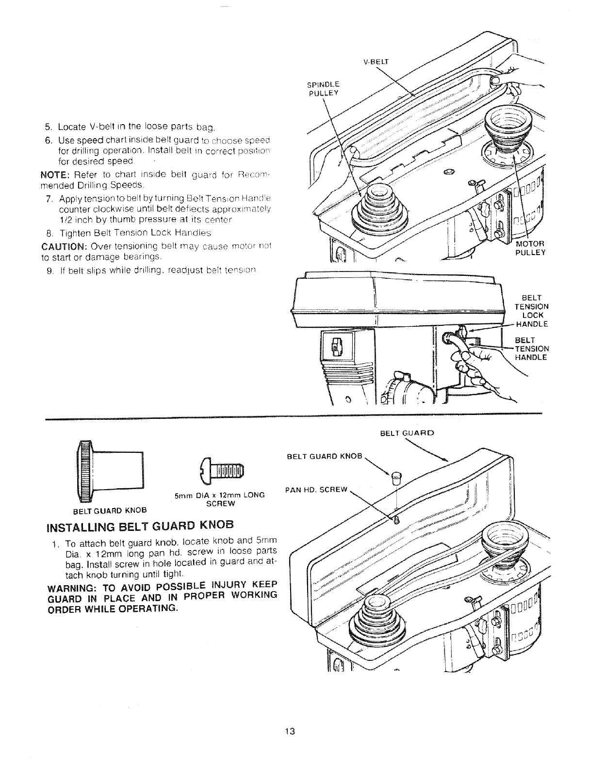
5. Locate V-belt in the loose parts bag.
6. Use speed chart inside belt guard to choose speed
for drilling operation. Install belt _ncorrect pos_t_on
for desired speed
NOTE: Refer to chart inside belt guard for Recc)m-
mended Drilling Speeds.
7. Apply tension to belt by turning Belt Tension Han:l e
counter clockwise until belt deflects app_oximateiy
!/2 inch by thumb pressure at _ts center
8. Tighten Belt Tension Lock Handles
CAUTION: Over tensioning belt may cause motor not
to start or damage bearings.
9. If belt slips while drilling, readjust belt tenson
V-BELT
\
SPINDLE
PULLEY
MOTOR
PULLEY
_. 1 _ BELT
..................,......... TENSION
;I LOCK
HANDLE
BELT GUARD
5ram DIA x 12ram LONG
SCREW
BELTGUARD KNOB
INSTALUNG BELT GUARD KNOB
t, To attach belt guard knob. locate knob and 5ram
Dia. x 12mm long pan hd. screw in loose parts
bag. Install screw in hole Iocaled in guard and at-
tach knob turning until tight.
WARNING: TO AVOID POSSIBLE INJURY KEEP
GUARD IN PLACE AND IN PROPER WORKING
ORDER WHILE OPERATING,
13
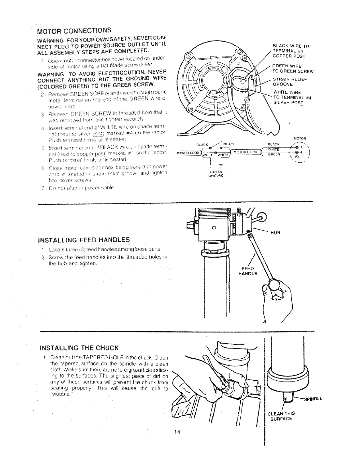
MOTOR CONNECTIONS
WARNING: FOR YOUR OWN SAFETY- NEVER CON-
NECT PLUG TO POWER SOURCE OUTLET UNTIL
ALL ASSEt_BLY STEPS ARE COMPL ETED,
WARNING; TO &VOID ELECTROCUTION, NEVER
CONNECT ANYTHING BUT THE GROUND WIRE
(COLORED GREEN} TO THE GREEN SCREW.
2 ,4, m_w_ GRE[fN :s,:REW a_r_ _nser; mrougr_ rounf_
,;era 0.-._m;;__ r-. *k- enu "_ m< GREEN w_re of
X,',_r',_,<,-t ,F-_[:Ft'47(;R[ZW m ff/roaGec no_e mat "
[_¢))t (t}*/1"*f _ W%
BLACK BLACK
_OWER CORg_ MOTOR CORD
GREEN
{G_OUND}
BLACK WIRE TO
L #1
COPPER POST
GREEN WIRE
TO GREEN SCREW
STRAIN RELIEF
GROOVE
WHITE WIRE
TO TERMINAL #4
SILVER POST
MOTOR
BLACK
WHITE
GREEN
INSTALUNG FEED HANDLES
! I OC_d_ _mrp_ t:'_ h:'_,d h_:JrKtIes amOr;q 'Dose paris
2 ff,c_e,',, the fe_c !_and_es lind lhe th,'eaded holes tn
FEED
HANDLE
HUB
INSTALLING THE CHUCK
Ciea_ out lhe TAPERED HOLE _nthe chuck, Clean
[ne taoered surface on the soindle w_th a clean
cioth Make sure mere are no Iore_gr_particles stick-
_g _o the surfaces The sHgnlest pece of d_rt on
any of these surfaces w_ll preveni the chuck from
sea[_ng properly This wH cause the drill to
_'wobDJe
14
PINDLE
CLEAN THIS
SURFACE
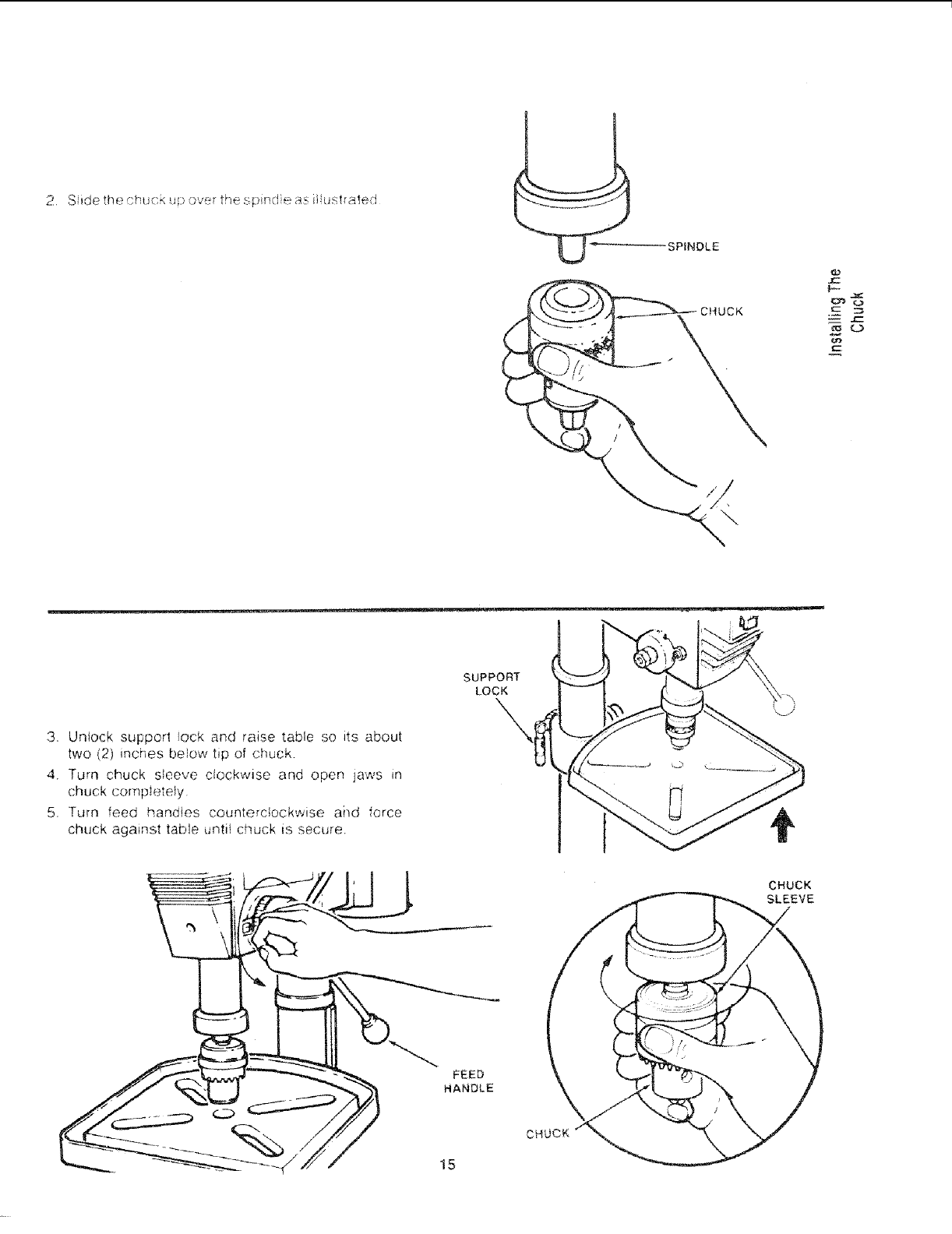
_SPINDLE
3. Unlock support lock and raise table so its about
two (2) inches below tip of chuck.
4. Turn chuck sleeve clockwise and open jaws _n
chuck comp_etefy
5. Turn feed handles counterclockwise ai]d force
chuck against table untii chuck is secure.
SUPPORT
LOCK
\
FEED
HANDLE
CHUCK
15
CHUCK
SLEEVE

ADJUSTING THE TABLE SQUARE
TO HEAD
NOTE: The comb _t_on sauare must be "true." See
'Unpacking and Checking Contents" section for
method,
1 Insert a preciston ground steel roe approximately
3" long into chuck and tighten,
2. With table raised to working height and locked on
column, place combination square flat on table be-
side rod
3. If an adjustment is necessary, loosen the set screw
under bevel lock with 3ram Hex L" wrench, then
loosen the table bevel lock with a 15/16" wrench.
_These adjLJstments are located under the tabie_
4. Align the table square to the roa by rotat=ng the
table until the square and rod are in line.
5 Retighten table bevel lock.
6. Retighten set screw,
LOCK
TABLE
/
BEVEL SCALE
NOTE: The bevel scale nas been included to provide
a quick method for bevehng the table to approx_ma[e
angles, If precise accuracy _s necessary, a square, or
other preciston measuring tool should be used to 0ost-
lion the table,
1 To use the bevel scale do the following:
a. Loosen set screw and table bevel lock (see step
3 above),
b_ Move table so desired angle on bevel scale is
straight across from zero line on table support
c. Retighten table bevel lock and set screw.
POINTER \
SCALE
TABLE
/
16
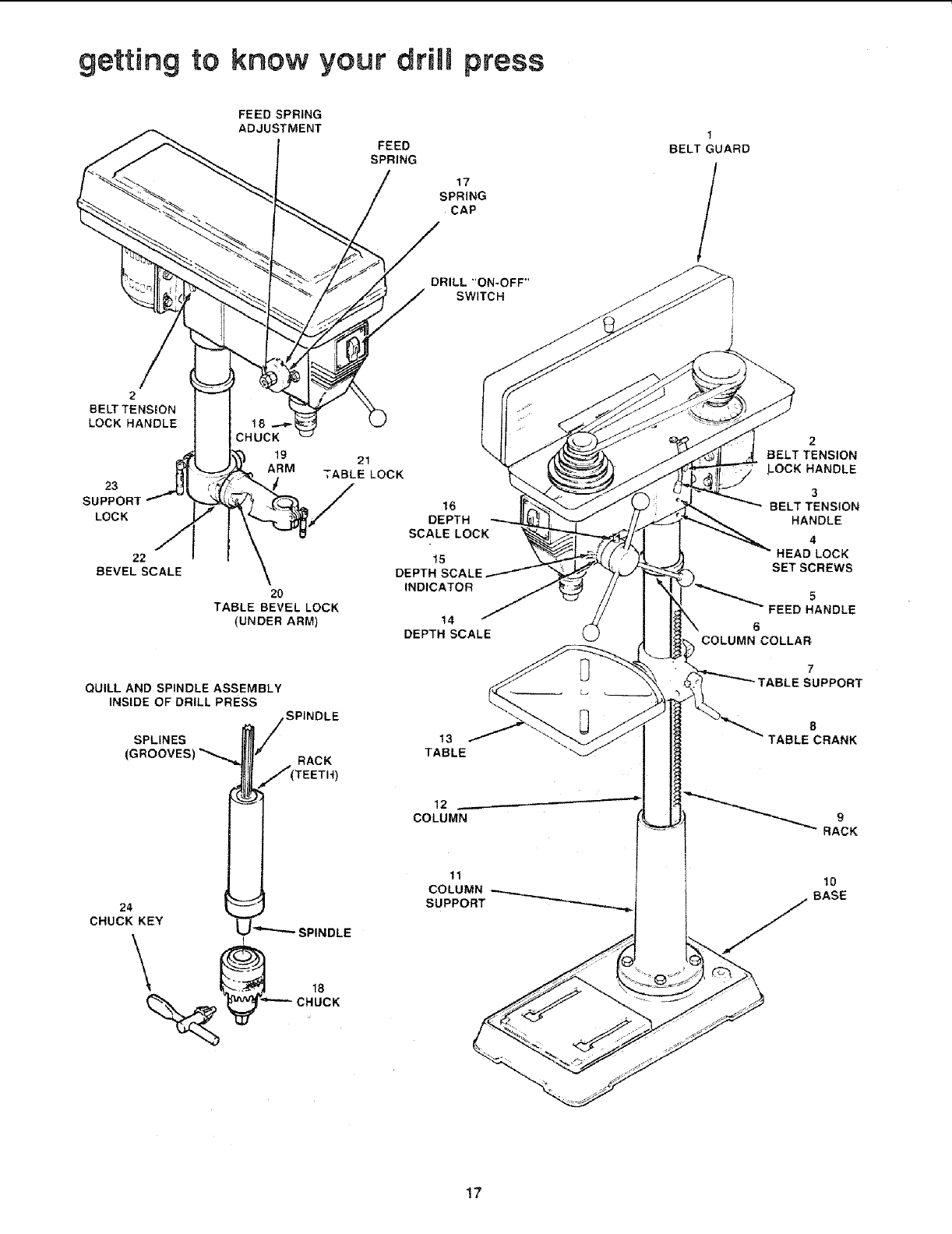
getting to know your driUmpress
FEED SPRING
ADJUSTMENT
FEED
SPRING
17
SPRING
CAP
DRILL "ON-OFF"
SWITCH
1
BELT GUARD
/
2
BELT TENSION
LOCK HANDLE
23
LOCK
19 21
ARM TABLE LOCK
16
DEPTH
SCALE LOCK
22 15
BEVEL SCALE
20
TABLE BEVEL LOCK
(UNDER ARM)
QUILL AND SPINDLE ASSEMBLY
INSIDE OF DRILL PRESS
SPINDLE
RACK )
SPLINES
(
24 t
CHUCK KEY SPINDLE
INDICATOR
14
DEPTH SCALE
13
TABLE
12
COLUMN
11
COLUMN
SUPPORT
l
2
BELT TENSION
LOCK HANDLE
3
BELT TENSION
HANDLE
4
HEAD LOCK
SET SCREWS
5
FEED HANDLE
6
COLUMN COLLAR
7
5SUPPORT
8
TABLE CRANK
RACK
10
BASE
17
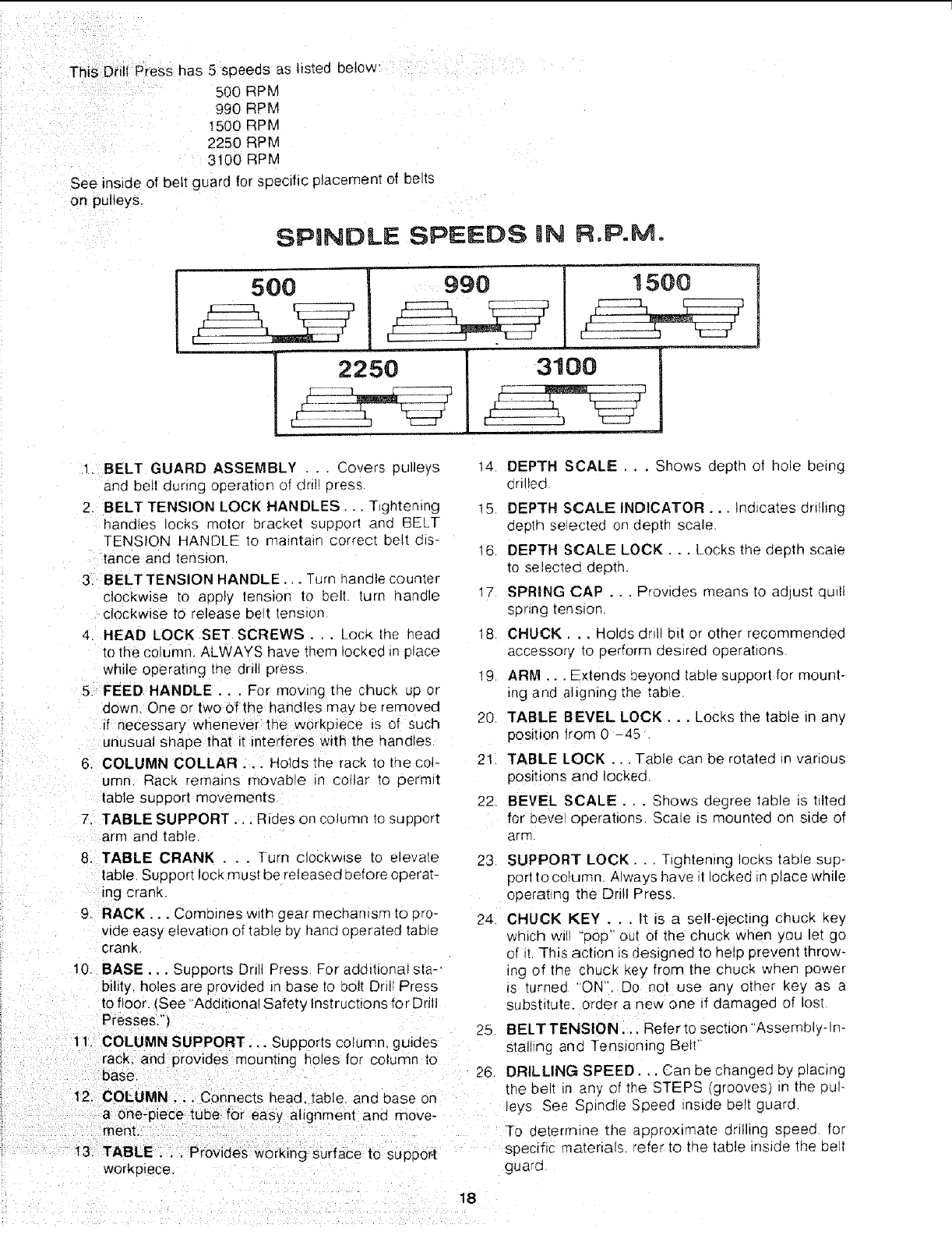
This Dr_ll Presshas 5 soeeds as listed below:
500 R3M
990 _>M
1500 qPM
2250 RPM
3t00 RPM
See inside of belt guard for specific placement of belts
on pulleys,
SPINDLE SPEE#S iN R.P.Mo
500 1500
2250
[
3100
1. BELT GUARD ASSEMBLY . . . Covers pulleys
and beit dunng operation of dri! 3ross
2. BELT TENSION LOCK HANDLES... T ghtenmg
bandies locks motor bracket support and BELT
TENSION HANDLE [o ma_ntaln correct belt d_s-
lance and tension.
3, BELTTENSlON HANDLE... Turn handle counter
clockwise to apply tension to belt turn handle
c!ockwise to release bett tension
4. HEAD LOCK SET SCREWS ... Lock the head
to the column, ALWAYS have them locked in p_ace
while operanng [ne drill press
5_ FEED HANDLE... For moving _ne chuck up or
down. One or two of the handles may oe removed
if necessary whenever the workplece _s of such
unusual shape that it interferes with the handles
6. COLUMN COLLAR .. Holds the rack to the col-
umn Rack remains movable ir collar to permit
table suoport movements
7. TABLE SUPPORT.,. Rides on column _o support
arm aria table.
8. TABLE CRANK _..Turn clockwise to elevate
table. Support lock must be released before operat-
ing crank
9_ RACK... Combines with gear mechamsm to _ro-
vide easy elevation of table by hand operated talale
crank
10. BASE,.. Supports Drill Press For additional sta-
bility, holes are orovided Jn base to bolt Dril Press
to floor. _See "Additional Safet_ instructions for Drill
Presses."/
t 1. COLUMN SUPPORT... Supports column, guides
rack. and provides mounting holes for column to
base.
12, COLUMN.,. Connects head, table and base on
a one-piece tube
merit, for easy alignment and move-
t3_ TABLE,,. Provides working Surface to support
workoiece.
14 DEPTH SCALE ... Shows depth of hole being
drilled
!5 DEPTH SCALE INDICATOR... Indicates drilling
oepth se4ected on depth scale
16. DEPTH SCALE LOCK... Locks [no depth scale
to selected oeptn.
17 SPRING CAP ... Provides means to aG ust quill
spring tension.
18 CHUCK... Holds dnll b_t or other recommended
accessory [o oerform desired operations
19, ARM... Extends beyond table support for mount-
_ng ano aligning the table
20 TABLE BEVEL LOCK... LOCKSthe table in any
posJuon from 0 -45
21 TABLE LOCK... Table can be rotated n various
positions and locked
22 BEVEL SCALE... Shows degree table is tilted
for beve operations. Scale is mounted on side of
arm.
23 SUPPORT LOCK.. Tightening locks taole sup-
port to column. Always have t locked _n 31ace while
operating the Drill Press.
24 CHUCK KEY . .. It is a self-electing chuck key
which wl "'oop" OUt of the chuck when you let go
of it This action is designed to help prevent throw-
ing of the chuck Key from the ChUCk when power
_s turneo "ON'. Do not use any other key as a
substitute, order a new one if damaged of lost
25 BELT TENSION. ,. Refer to section "Assembly-ln-
stallTng ano Tensioning Belt'
26 DRILLING SPEED... Can be changed by placing
the belt _n any of tr_e STEPS grooves _nthe pul-
leys See Spindle Speed _nslde belt guard
To deterrntne rtqe approximate drltlllqg speed for
specific materials refer to the table inside tne belt
guard
18
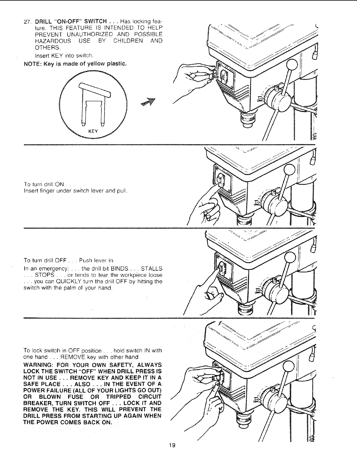
27 DRILL "ON-OFF" SWITCH . . , Has locking fea-
ture. THIS FEATURE IS INTENDED TO HELP
PREVENT UNAUTHORIZED AND POSSIBLE
HAZARDOUS USE BY CHILDREN
OTHERS.
Insert KEY into switch.
NOTE: Key is made of yellow plastic.
AND
To tum drill ON , .
Insert finger under switch lever and puli.
%..f._-J
To turn drill OFF... Push lever in
In an emergency: .., the drill bit BINDS. ,. STALLS
.,.STOPS . . . or tends to tear the workpiece loose
•. you can QUICKLY turn the dri OFF By hitting the
switch with the palm ol your hand.
To lock switch in OFF position .hotd sw_tclq IN with
one hand . REMOVE key w_ti_ other hand
WARNING: FOR YOUR OWN SAFETY, ALWAYS
LOCK THE SWITCH "OFF" WHEN DRILL PRESS IS
NOT IN USE ... REMOVE KEY AND KEEP IT IN A
SAFE PLACE . ,. ALSO . . . IN THE EVENT OF A
POWER FAILURE (ALL OF YOUR LIGHTS GO OUT)
OR BLOWN FUSE OR TRIPPED CIRCUIT
BREAKER, TURN SWITCH OFF ,..LOCK iT AND
REMOVE THE KEY. THIS WILL PREVENT THE
DRILL PRESS FROM STARTING UP AGAIN WHEN
THE POWER COMES BACK ON,
/,
f
19
i,'_i_ii_i_i_i_?, _ , i_ i i_
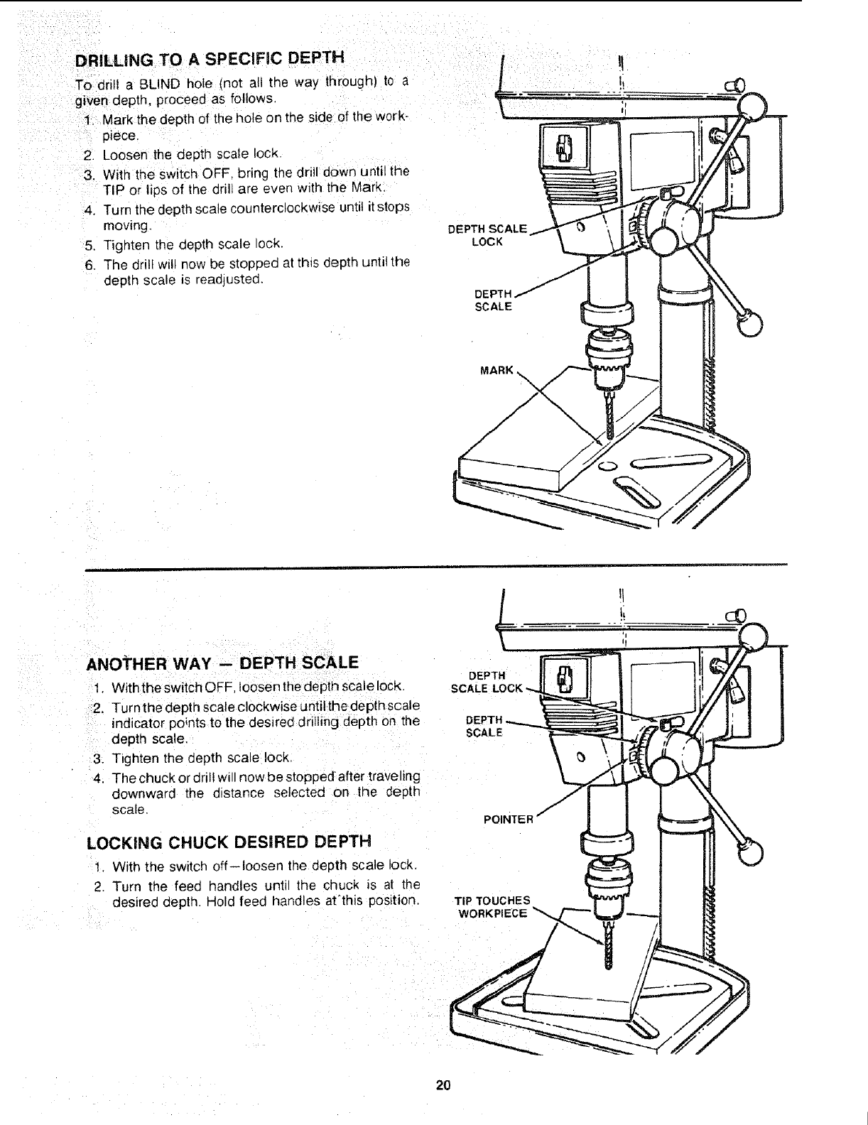
DRILLING TO A SPECIFIC DEPTH" tt
To drill a BLIND hole (not all the way through) to a .... !i
given depth proCeed as follows, ii
tMark the depth of the hole on the side of the work-
piece.
2: Loosen the depth scale !ock.
With the Switch OFF, bring the drill down until the
TIP or lips of the drill are even with the Mark:
4. Turn the depth scale counterclockwise until it stops
moving. DEPTH SCALE
5, Tighten the depth scale lock. LOCK
6, The drill will now be stopped at this depth until the
depth scale is readjusted. DEPTH
SCALE
MARK
ANOTHER WAY -- DEPTH SCALE
1. With the switch OFF. loosen the depth scale lock.
2. Turn the depth scale clockwise until the aepth scale
indicator points to the desired drilling depth on the
depth scale.
3, Tighten the eepth scare lock,
4. The chuck or drill will now be stopped after traveling
downward the d_stance selected on the _epth
scale.
LOCKING CHUCK DESIRED DEPTH
1. With the sw_tch off--loosen the depth scale lock
2, Turn the feed handles until the chuck is at the
desired depth Hold feed handles at'this position,
DEPTH
SCALE
POINTEI
TIP TOUCHES
WORKPIECE'_'%
2O
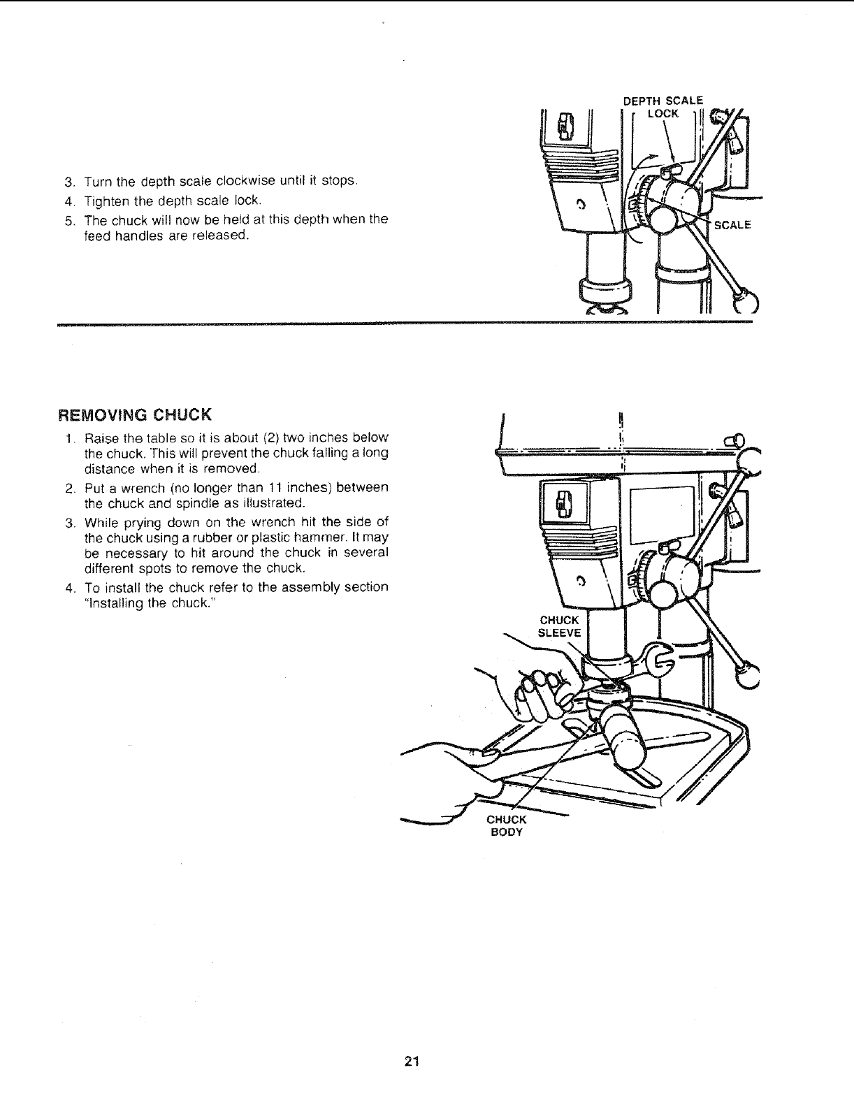
3. Turnthedepthscaleclockwiseuntilit stops,
4. Tightenthedepthscalelock.
5. Thechuckwillnowbeheldatthisdepthwhenthe
feedhandlesarereleased.
DEPTH SCALE
LOCK
REMOVING CHUCK
1. Raise the table so it is about (2) two inches below
the chuck, This will prevent the chuck falling a long
distance when it is removed.
2. Put a wrench (no longer than 11 inches) between
the chuck and spindle as illustrated.
3. While prying down on the wrench hit the side of
the chuck using a rubber or plastic hammer. It may
be necessary to hit around the chuck in several
different spots to remove the chuck.
4. To install the chuck refer to the assembly section
"Installing the chuck."
CHUCK
CHUCK
BODY
21
basic d tl( press operation
L;
owthef0 owng nstruct ons for operating your dr -- Never do any work "FREEHAND" (hand-
pres_ to get the best results and to minimize the likeli, hod ng workp ece rather than support lg t
h oao!persona injury, onthetab elexceptwhenpolishing
WARNING: FOR YOUR OWN SAFETY, ALWAYS - Securely lock Head and Support to Column,
OBSERVE THE SAFETY PRECAUTmONS HERE AND
ON PAGES 2, 3, AND 4.
1. Protection: Eyes, Hands, Face Ears and Body
WARNING: TO AVOID BEING PULLED iNTO
THE SPINNING TOOL --
1. Do NOT wear:
-- gloves
-- necktie
-- loose clothing
-- jewelry
2. Do tie back long hair
a. If any part of your drill press is missing, malfunc-
tioning, has been damaged or broken.., such
as the motor switch, or other operating control,
a safety device or the power cord , , . cease
operating immediately until the particular part
_s properly repaired or replaced.
b. Never place your fingers in a position w'here
they could contact the dril or other cuttmg tool
il the worKpiece should unexpectedly shift or
your hand should sl o.
c. To avoid injury from parts thrown by the spnng
follow instructions exactly as given and shown
in adjusting spring tensmon of quill.
d To prevent the workpiece from oemg torn from
your hands, spinning of the tool shattering the
too! or being thrown, always properly support
your work so it won't shift or bind on the tool:
-- Always position BACKUP MATERIAL (use
beneath the workp_ece) to contact the left
side of the column.
-- Whenever possible, position the WORK-
PIECE to contact the left side of the col-
umn--_r it is too short or the table is tilted.
clamp solidly to the table, use table slots or
clamping ledge around the outside edge of
the table.
When using adrill press VICE. always fasten
it to the table,
Table Arm to support, and Table to Table
Arm before operating drill press.
-- Never move the Head or Table while the
tool is running.
iBefore starting the operation, jog the motor
switch to make sure the drill or other cutting
tool does not wobble or cause vibration.
- If a workpiece overhangs the table such taht
it will fall or tip if not held, clamp it to the
table or provide auxiliary support.
Use fixtures for unusual operations to
adequately hold, guide and position work-
piece.
-- Use the SPINDLE SPEED recommended
for the specific operation and workpiece ma-
terial check the panel inside the pulley
guard cover for drilling information: for ac-
cessories, refer to the instructions provided
w_th the accessories.
f. Never climb on the drill press Table, it could
break or pull the entire drill press down on you.
g Turn the motor Switch Off and put away the
Switch Key when leaving the drill press.
h To avoid mnjuryfrom thrown work or tool contact,
do NOT oerform layout, assembly, or setup
work on the table while the cutting tool is rotat-
ing.
2. Use only accessories designed for this drill
press to avoid serious injury from thrown bro-
ken parts or work pieces.
a. Holesaws must NEVER be operated on this drill
press at a speed greater than 400 RPM.
b. Drum sanders must NEVER be operated on
this dril press at a speed greater than 1800
RPM.
c. Do not install or use any drill that exceeds 7" in
length or extends 6" below the chuck jaws, They
can suddenly bend outward or break.
d. Do not use wire wheels, router bits, shaper cut-
ters. circle (fly) cutters or rotary planers on the
drill press,
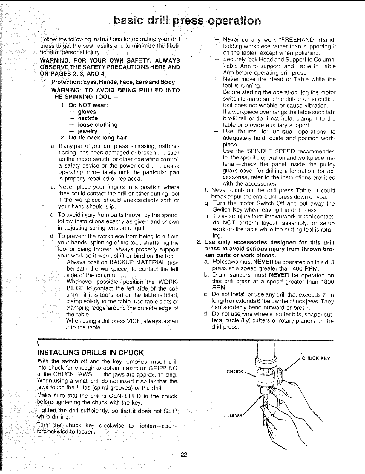
INSTALLING DRILLS iN CHUCK
With the switch off and the key removed (nsert drill
into chuck far enough to obtai_ maximum GRIPPING
of the CHUCK JAWS the jaws are approx. 1" long.
When using a small drill do not insert it so far that the
jaws touch the flutes (spiral grooves) of the drill,
Make sure that the drill is CENTERED in the chuck
before tightening the chuck with the key.
Tighten the drill sufficiently, so that it does not SLIP
while drilling.
Turn the chuck key clockwise to tighten--coun-
terclockwise to loosen.
KEY
22
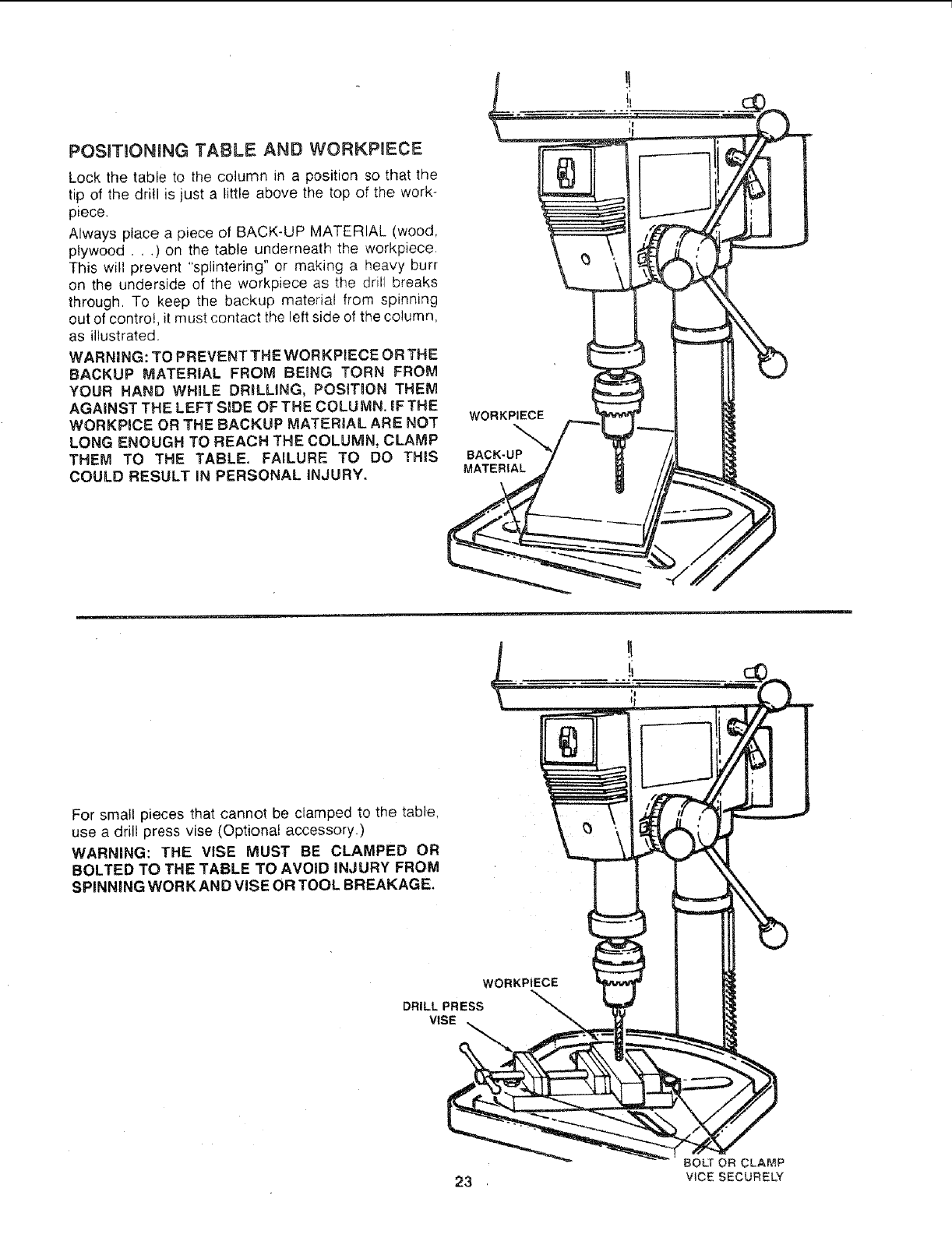
POSITIONING "TABLE AND WORKPIECE
Lock the table to the column in a position so that the
tip of the drill is just a little above the top of the work-
piece.
Always place a piece of BACK-UP MATERIAL (wood,
plywood. , .) on the table underneath the workpiece.
This will prevent "splintering" or making a heavy burr
on the underside of the workpiece as the drill breaks
through, TO keep the backup material from spinning
out of control, it must contact the left side of the column,
as illustrated.
WARNING: TO PREVENT THE WORKPIECE OR THE
BACKUP MATERIAL FROM BEING TORN FROM
YOUR HAND WHILE DRILLING, POSIT_ON THEM
AGAINST THE LEFT SIDE OF THE COLUMN. iF THE
WORKPICE OR THE BACKUP MATERIAL ARE NOT
LONG ENOUGH TO REACH THE COLUMN, CLAMP
THEM TO THE TABLE. FAILURE TO DO THIS
COULD RESULT IN PERSONAL INJURY.
WORKPIECE
BACK-UP
MATERIAL
For small pieces that cannot be clamped to the table,
use a drill press vise (Optional accessory.)
WARNING: THE VISE MUST BE CLAMPED OR
BOLTED TO THE TABLE TO AVOID INJURY FROM
SPINNING WORK AND VISE OR TOOL BREAKAGE.
WORKPiECE
DRILL PRESS
VISE
BOLT OR CLAMP
23 VlCESECURELY
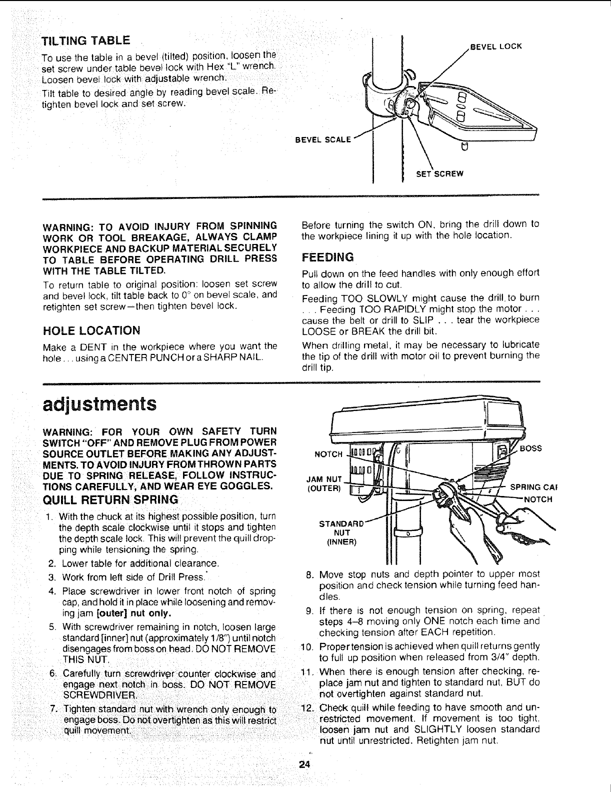
TILTING TABLE
i
: : To use the table in a bevel ttilted) position, loosen the
set screw under table bevel lock with Hex "L" wrenchl
Loosen bevel Iodk With adjustabie Wrench:
iTilt tab e to desired angle by reading bevel scale. Rei
tighten bevel lock and set screw.
BEVEL (3
SET SCREW
:VEL LOCK
WARNING: TO AVOID INJURY FROM SPINNING
WORK OR TOOL BREAKAGE, ALWAYS CLAMP
WORKPIECE AND BACKUP MATERIAL SECURELY
TO TABLE BEFORE OPERATING DRILL PRESS
WITH THE TABLE TILTED.
To return table to original position: loosen set screw
and bevel lock, tilt table back to 0° on bevel scale, and
retighten set screw--then tighten bevel lock.
HOLE LOCATION
Make a DENT in the workpiece where you want the
hole.., using a CENTER PUNCH or a SHARP NAIL.
Before turning the switch ON, bring the drill down to
the workpiece lining it up with the hole location,
FEEDING
Pull down on the feed handles with only enough effort
to allow the drill to cut.
Feeding TOO SLOWLY might cause the drillto burn
. . , Feeding TOO RAPIDLY might stop the motor...
cause the belt or drill to SLIP ... tear the workpiece
LOOSE or BREAK the drill bit.
When drilling metal, it may be necessary to lubricate
the tip of the drill with motor oi! to prevent burning the
drill tip.
adjustments
WARNING: FOR YOUR OWN SAFETY TURN
SWITCH "OFF" AND REMOVE PLUG FROM POWER
SOURCE OUTLET BEFORE MAKING ANY ADJUST-
MENTS. TO AVOID INJURY FROM THROWN PARTS
DUE TO SPRING RELEASE, FOLLOW INSTRUC-
TIONS CAREFULLY, AND WEAR EYE GOGGLES.
QUILL RETURN SPRING
NOTCH
JAM NUT
(OUTER)
BOSS
SPRING CAI
1. With the chuck at its highest possible position, turn
the depth scale clockwise until it stops and tighten
the depth scale lock. This will prevent the quill drop-
p_ngwhile tensioning the spring.
2. Lower table for additional clearance
3. Work from left side of Drill Press."
4. Place screwdriver in lower front notch of spring
cap, and hold it in place while loosening and remov-
ing jam [outer] nut only.
5. With screwdriver remaining in notch, loosen large
standard [inner] nut (approximately 1/8") until notch
disengages from boss on head. DO NOT REMOVE
THIS NUT.
6. Carefully turn screwdrMpr counter clockwise and
engage next notch in boss. DO NOT REMOVE
SCREWDRIVER
NUT
(INNER)
8, Move stop nuts and depth pointer to upper most
position and check tension whi_e turning feed han-
dles.
9. If there is not enough tension on spring, repeat
steps 4-8 moving only ONE notch each time and
checking tension after EACH repetition.
10. Proper tension is achieved when quilt returns gently
to full up position when released from 3/4" depth.
11. When there is enough tension after checking, re-
place jam nut and tighten to standard nut, BUT do
not overtighten against standard nut.
7. Tighten standard nut with wrench only enough to 12. Check quill while feeding to have smooth and un-
engage boss. Do not overtighten as th s w restr Ct restricted movement If movement s too t ght
quill movement, loosen jam nut and SLIGHTLY loosen standard
nut until unrestricted. Retighten jam nut.
24
maintenance
WARNING FOR YOUR OWN SAFETY, TURN
SW_TCH "OFF" AND REMOVE PLUG FROM POWER
SOURCE OUTLET BEFORE MAINTAINRNG OR LUB-
RICATaNG YOUR DRILL PRESS.
Frequently blow out any dust that may accumulate in-
side the motor.
A coat of furniture-type paste wax applied to the table
and column will help to keep the surfaces clean.
WARNING: TO AVORD SHOCK OR F_RE HAZARD,
IF THE POWER CORD nS WORN OR CUT, OR DAM-
AGED IN ANY WAY, HAVE IT REPLACED AM-
MEDIATELY.
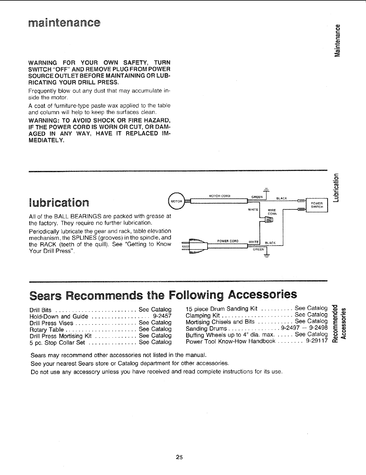
lubrication
All of the BALL BEARINGS are packed with grease at
the factory. They require no further lubrication.
Periodically lubricate the gear and rack, table elevation
mechanism, the SPLINES (grooves) in the spindle, and
the RACK (teeth of the quill). See "Getting to Know
Your Drill Press".
MOTORCORD
POWER CORD
O
"___,
Sesrs
Drill Bits ......................... See Catalog
Hold-Down and Guide .................. 9-2457
Drill Press Vises ................... See Catalog
Rotary Table ...................... See Catalog
Drill Press Mortising Kit ............. See Catalog
5 pc. Stop Collar Set ............... See Catalog
Recommends the Following Accessories
15 piece Drum Sanding Kit .......... See Catalog "_
Clamping Kit See Catalog "_ -_-
Mortising Chisels and Bits ........... See Catalog _ o
Sanding Drums ................ 9-2497 -- 9-2498 E
Buffing Wheels up to 4" dia, max. See Catalog o co
Power Tool Know-How Handbook ........ 9-29117 t,-
Sears may recommend other accessories not listed in the manual.
See your nearest Sears stere or Catalog department for other accessories_
Do not use any accessory unless you have received and read complete instructions for its use.
25
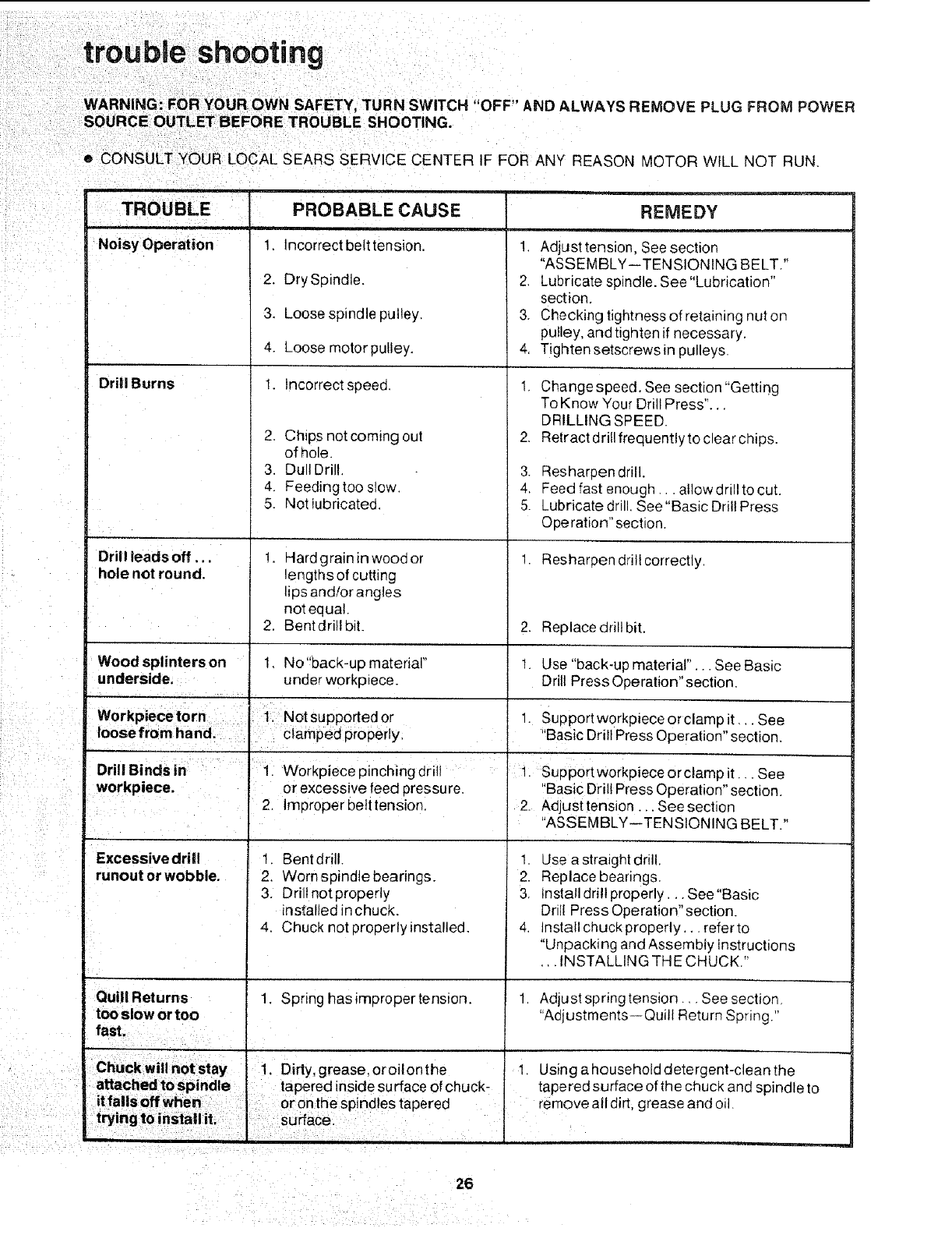
trouble shooting
WARNING: FOR YOUR OWN SAFETY TURN SWITCH "OFF" AND ALWAYS REMOVE PLUG FROM POWER
SOURCE OUTLET BEFORE TROUBLE SHOOTING.
eCONSULT YOUR LOCAL SEARS SERVICE CENTER IF FOR ANY REASON MOTOR WILL NOT RUN.
TROUBLE
i
Noisy Operation
Drill Burns
Drill leads off...
hole not round.
REMEDY
PROBABLE CAUSE
1. Incorrect belt tension.
2. Dry Spindle.
3. Loose spindle pulley.
4. Loose motorpulley.
!. Incorrect speed.
2. Chips not coming out
of hole.
3. Dull Drill.
4. Feedingtoo slow.
5. Not lubricated.
1. Hardgrainin wood or
lengths of cutting
lips and/or angles
notequa!.
2. Bent dritl bit.
1, No"back-up material"
under workpiece.
1. Adjusttension, Seesection
"ASSEMBLY--TENSIONING BELT."
2. Lubricate spindle. See "Lubrication"
section.
3. Checking tightness of retaining nut on
pu!ley, and tighten if necessary.
4. Tighten setscrews in pulleys.
1. Change speed. See section "Getting
To Know Your Drill Press"...
DRILLING SPEED
2. Retract dril! frequently to clear chips.
3• Resharpen drill.
4. Feed fast enough.., allow drill to cut.
5. Lubricate drill. See "Basic Drill Press
Operation" section.
1. Resharpen drill correctly.
2. Replace drill bit.
Wood splinters on t. Use "back-up material"..• See Basic
underside. Drill Press Operation" section,
'kpi epin hingd
Drill Binds in J 1. Wor ec c rill
workpiece, or excessive feed pressure.
2. Improper betttension.
Excessive drill 1. Bent drill.
runout or wobble. 2, Worn spindle bearings.
3. Drill notproperly
installedin chuck,
4, Chuck not properly installed,
1. Spring hasimpropertension.
Quill Returns
too slow or too
fast.
1. Supportwerkpieceorclampit.,, See
"Basic Drill Press Operation" section.
1. Supportworkpieceorclamp it... See
Basic Drill Press Operat on sect on.
2. Adjust tension ... See section
"ASSEMBLY--TENS ON NG BELT."
1. Use a straight drill.
2. Replace bearings.
3. Install drill properly... See"Basic
Dri!l Press Operation" section.
4. Install chuck properly,., referto
"Unpacking and Assembly Instructions
... INSTALLING THE CHUCK."
1. Adjust spring tension... See section.
"Adjustments--Quill Return Spring."
1. Using a household detergent-clean the
tapered surface of the chuck and spindle to
remove all dirt, grease and oil.
26
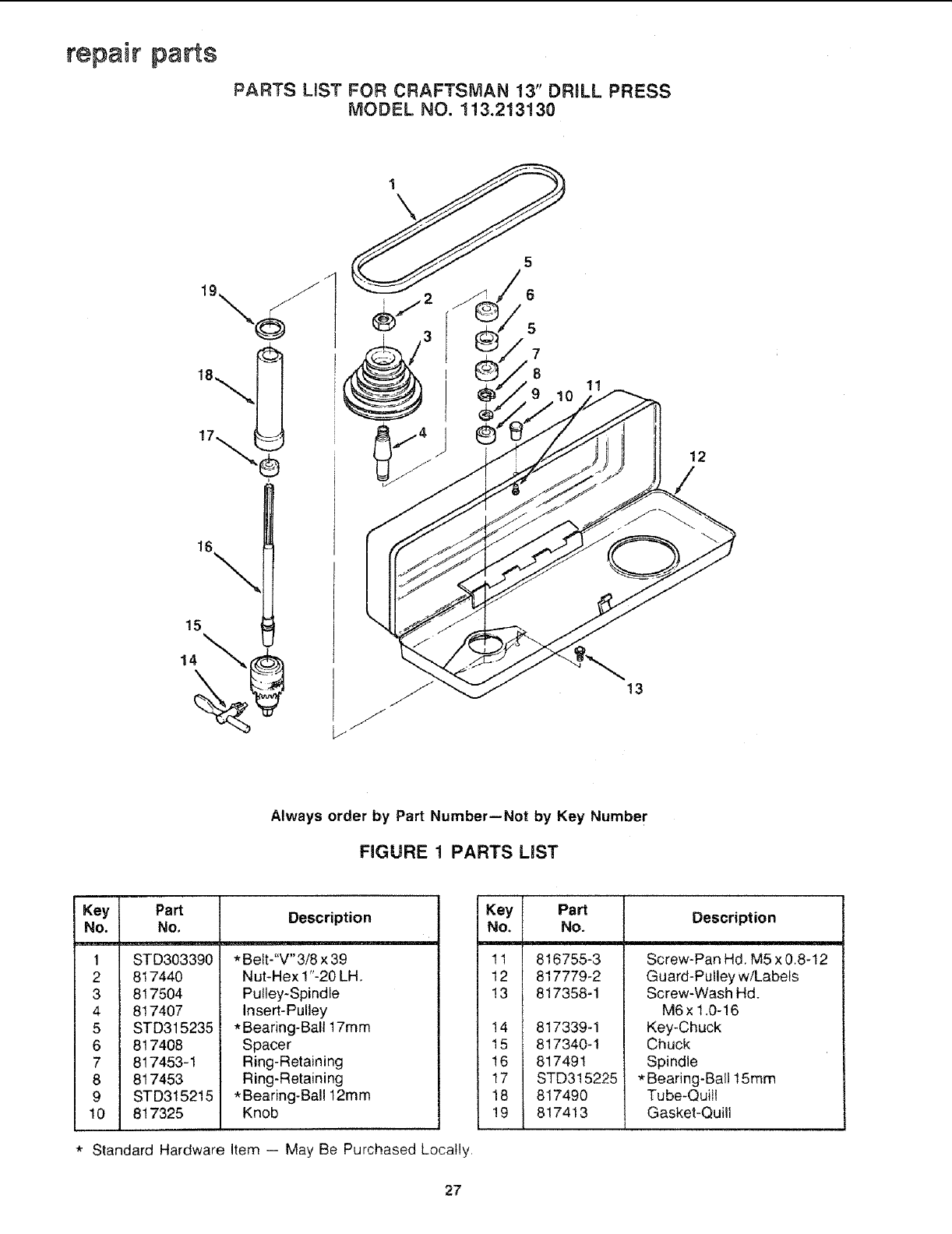
repair parts
PARTS LmST FOR CRAFTSMAN 13" DRILL PRESS
MODEL NO. 113.213130
1\
16
5
6
5
7
8
12
15
13
Always order by Part Number--Not by Key Number
FIGURE 1 PARTS LiST
Key Part
No. No.
1 STD303390
2 817440
3 817504
4 8! 7407
5 STD315235
6 817408
7 817453-1
8 817453
9 STD315215
10 817325
Description
*Belt-"V" 3/8 x 39
Nut-Hex 1"-20 LH.
Pulley-Spindle
Insert-Pulley
*Bearing-Ball 17ram
Spacer
Ring-Retaining
Ring-Retaining
*Bearing-Ball 12mm
Knob
*Standard Hardware Item -- May Be Purchased Locally,
Key Part
No. No.
11 816755-3
12 817779-2
!3 817358-1
!4 817339-1
15 817340-1
!6 817491
17 STD315225
18 817490
!9 817413
Description
Screw-Pan Hd. M5 x 0.8-12
Guard-Pulley w/Labels
Screw-Wash Hd.
M6x 1.0-16
Key-Chuck
Chuck
Spindle
* Bearing-Ball 15mm
Tube-Quill
Gasket-Quill
27
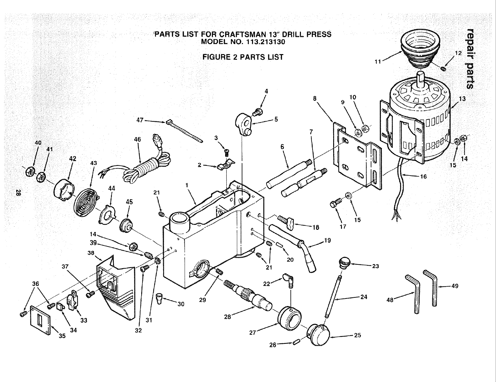
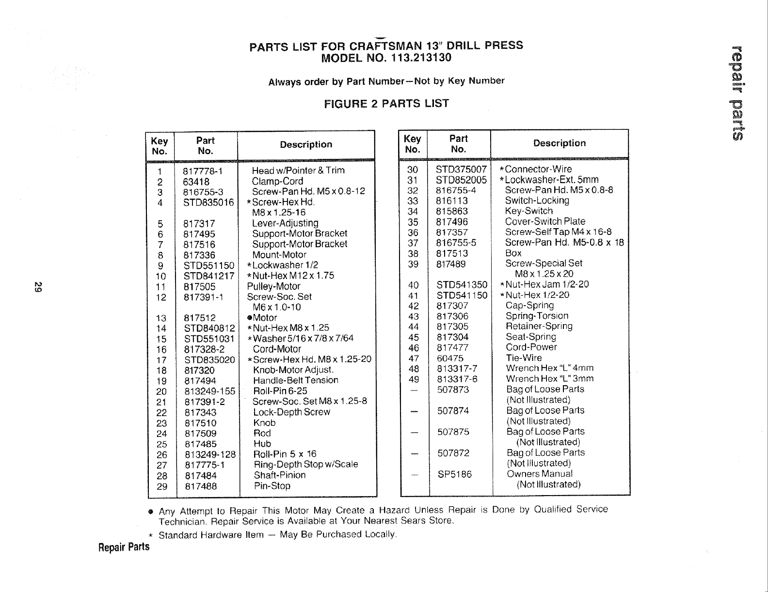
PARTS LIST FOR CRAFTSMAN 13" DRILL PRESS
MODEL NO. 113.213130
FIGURE 2 PARTS LIST
42
37
36
34
35
21
38
29
30
33 31
32
3\
7
6\
20
21
22,,.,-'_(_
28
27
26
810
\9
\\\
.._----49
14
15
t4:)
v
PARTS LIST FOR CRAFTSMAN 13" DRILL PRESS
MODEL NO. 113.213130
Always order by Part Number--Not by Key Number
FIGURE 2 PARTS LIST
Key IPa_
No.L_ %___
1 817778-1
63418
816755-3
4 STD835016
817317
817495
7 817516
8 817336
90 STD551150
STD841217
11 817505
12 817391-1
13 817512
14 STD840812
15 STD551031
16 817328-2
17 STD835020
18 817320
19 817494
20 813249-155
21 817391-2
22 817343
23 817510
24 817509
25 817485
26 813249-128
27 817775q
28 817484
29 i 817488
]
Description
Head w/Pointer & Trim
Clamp-Cord
Screw-Pan Hd. M5 x 0,8-12
* Screw-Hex Hd,
M8x 1.25-16
Lever-Adjusting
Support-Motor Bracket
Support-Motor Bracket
Mount-Motor
* Lockwasher 1/2
*Nut-Hex M12x 1,75
Pulley-Motor
Screw-Soc. Set
M6x1.0-10
oMotor
* Nut-Hex M8 x 1.25
*Washer 5/16 x 7/8 x 7/64
Cord-Motor
* Screw-Hex Hd. M8 x 1.25-20
Knob-Motor Adjust.
Handle-Belt Tension
Roll-Pin 6-25
Screw-Soc. Set M8 x 1.25-8
Lock-Depth Screw
Knob
Rod
Hub
Roll-Pin 5 x 16
Ring-Depth Stop w/Scale
Shaft-Pinion
Pin-Stop
!
Key
No.
===ae_=m
30
31
32
33
34
35
36
37
38
39
40
41
42
43
44
45
46
47
48
49
Part
No.
STD375007
STD852005
816755-4
816113
815863
817496
817357
816755-5
817513
817489
STD54!350
STD541150
817307
817306
817305
817304
817477
60475
813317-7
813317-6
507873
507874
507875
507872
SP5186
Description
*Connector-Wire
*Lockwasher-Ext. 5mm
Screw-Pan Hd. M5 x 0.8-8
Switch-Locking
Key-Switch
Cover-Switch Plate
Screw-Self Tap M4 x 16-8
Screw-Pan Hd. M5-0.8 x 18
Box
Screw-Specia! Set
M8x1.25x20
*Nut-Hex Jam 1/2-20
*Nut-Hex 1/2-20
Cap-Spring
Spring-Torsion
Retainer-Spring
Seat-Spring
Cord-Power
Tie-Wire
Wrench Hex "L" 4ram
Wrench Hex "L" 3mm
Bag of Loose Parts
(Not !llustrated)
Bag of Loose Parts
(Not Illustrated)
Bag of Loose Parts
(Not Illustrated)
Bag of Loose Parts
(Not Illustrated)
Owners Manual
(Not I!lustrated)
• Any Attempt to Repair This Motor May Create a Hazard Unless Repair is Done by Qualified Service
Technician. Repair Service is Available at Your Nearest Sears Store,
• Standard Hardware Item -- May Be Purchased Locally.
Repair Parts
¢#
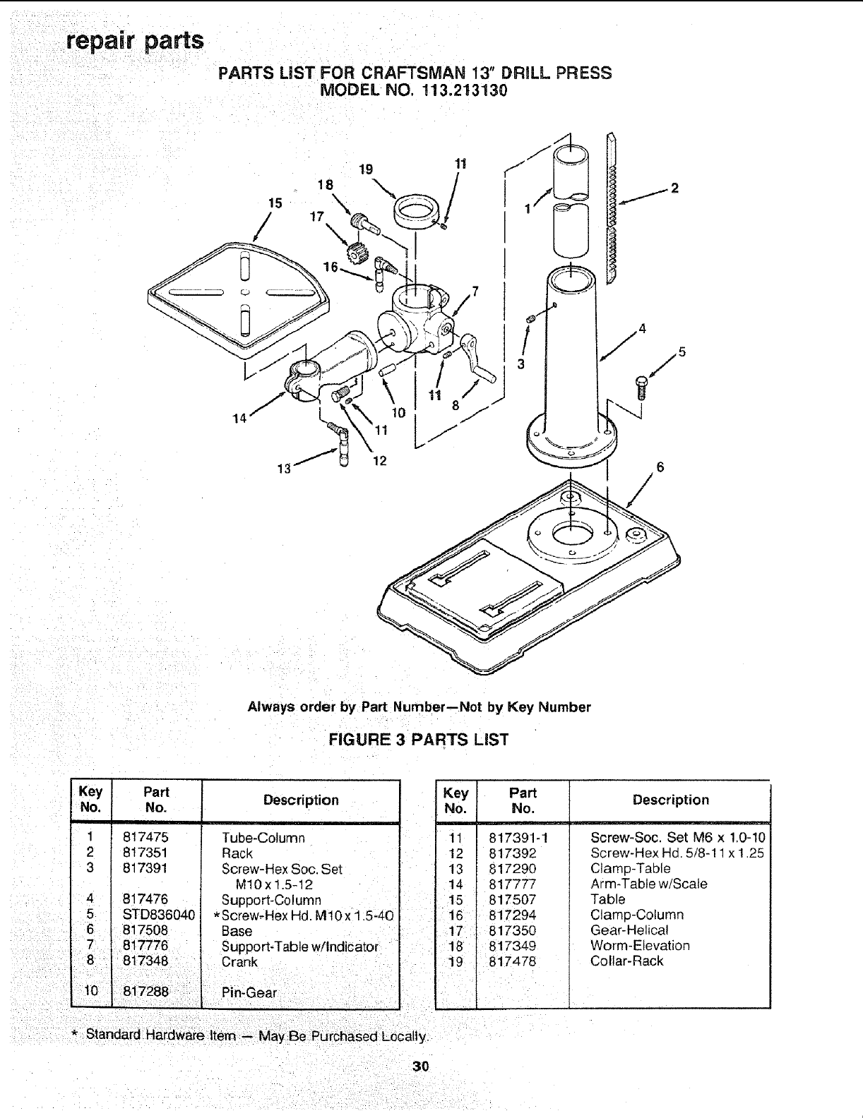
PARTS LiST FOR CRAFTSMAN 13" DRILL PRESS
MODEL NO. 113.213130
13
Always order by Part Number--Not by Key Number
FIGURE 3 PARTS LiST
Key
No.
1
I
41
5 i
6i
Part
No.
817475
817351
817391
817476
STD836040
817508
Description
Tube-Column
Rack
Screw-Hex Soc. Set
M10x1.5-12
Support-Column
*Screw, Hex Hd. M10x 1.5-40
Base
7 i 817776 Support-Table w/Indicator
8817348 , Crank
*Standard Hardware item -- May Be Purchased Loca!ly.
Key Part
No. No.
11 817391-1
12 817392
13 817290
14 817777
15 817507
16 817294
17 817350
18 817349
19 817478
Description
Screw-Soc. Set M6 x 1.0-10
Screw-Hex Hd. 5/8-11 x 1.25
Clamp-Table
Arm-Table w/Scale
Table
Clamp-Column
Gear-Helica!
Worm-Elevation
Collar-Rack
3O

NOTES
31
SERVmCE
MODEL NO.
!13o2!3!30
DR&L PRESS WnTH
MAXIMUM
DEVELOPED
2/3 HP MOTOR
HOW TO ORDER
REPAIRPARTS
LL
Now that you have purchased your '13-inch Drill Press, should
a need ever exist for repair parts or service, simply contact
any Sears Service Center and most Sears, Roebuck and Co.
stores. Be sure to provide all pertinent facts when you call
or visit,
The model number of your "13-inch Drill Press will be found
on a plate attached to the rear of the head.
WHEN ORDERING REPAIR PART&ALWAYS GIVE THE FOLLOWING
INFORMATION:
PARTNUMBER PART DESCRIPTION
MODEL NUMBER
113,2t3t30 NAME OF ITEM
MOTORIZED 13-INCH
FLOOR MODEL DRILL PRESS
All paris listed may be ordered from any Sears Service Center
and most Sears stores, if the parts you need are not stocked
locally, your order will be electronically transmitted to a Sears
Repair Paris Distribution Center for handling.
]
,,,._
Sold by SEARS, ROEBUCK AND CO., Chicago, IL 60684 U.S.A.
Part No. SP5186 Form No, SP5186-4 Printed in Taiwan 9/90
