Craftsman 113221720 User Manual TABLE SAW Manuals And Guides L0709427
CRAFTSMAN Saw Table Manual L0709427 CRAFTSMAN Saw Table Owner's Manual, CRAFTSMAN Saw Table installation guides
User Manual: Craftsman 113221720 113221720 CRAFTSMAN TABLE SAW - Manuals and Guides View the owners manual for your CRAFTSMAN TABLE SAW #113221720. Home:Tool Parts:Craftsman Parts:Craftsman TABLE SAW Manual
Open the PDF directly: View PDF ![]() .
.
Page Count: 48
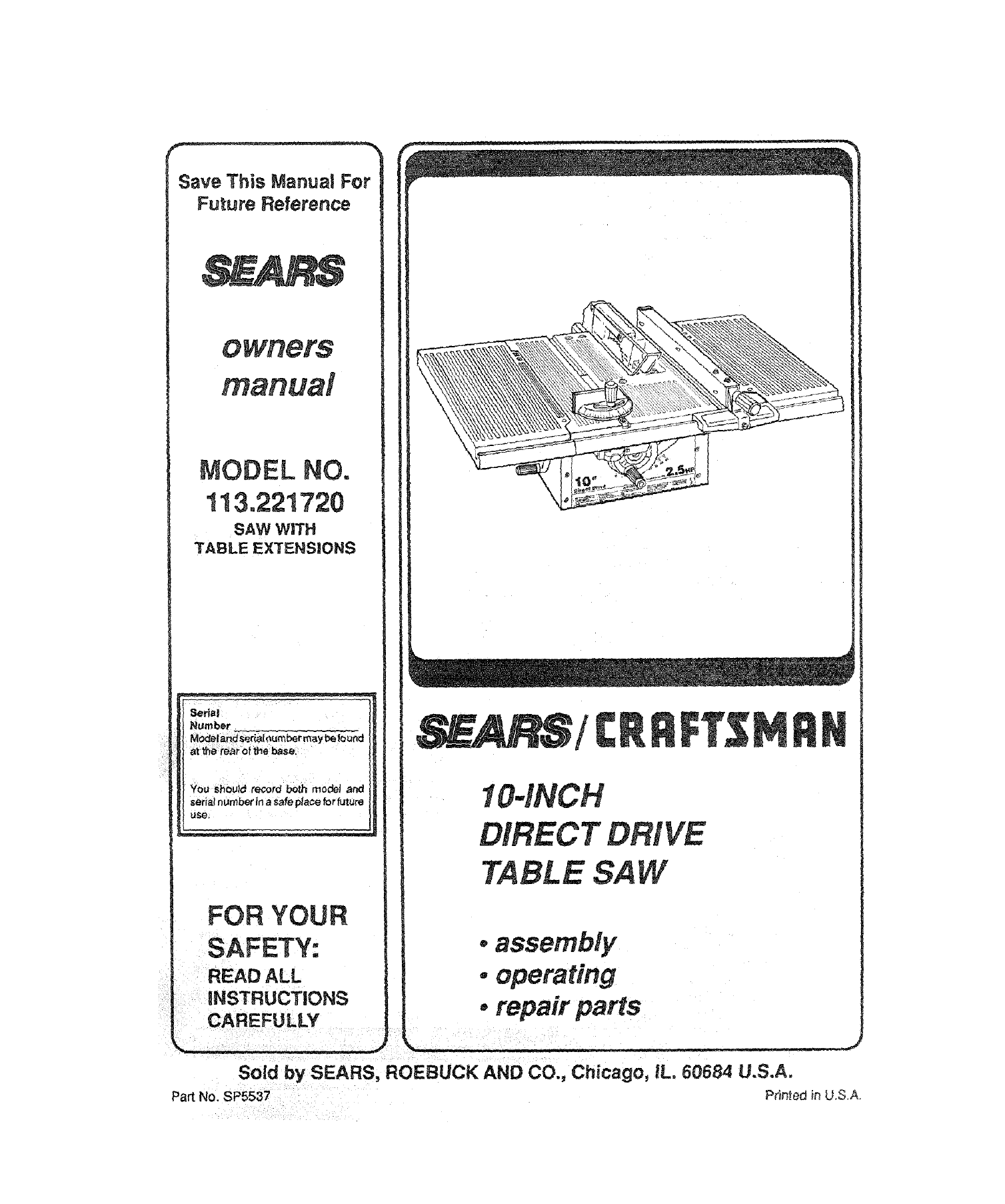
Save This Manual For
Future Reference
FOR YOUR
E
SAF TY.
BEAD ALL
INSTRUCTIONS
CAREFULLY
/
IOqNCH
DIRECT IVE
TABLE SAW
.assembly
.operating
•repair parts
Sold by SEARS, ROEBUCK AND CO., Chicago, iL. 60684 U.S.A.
Part No. SP5537 Pr_n._eain U.S,A,
WARRANTY SERVICE iS AVAILABLE BY SIMPLY" CONTACTING "irHENEAREST SEARS SERV_E
CF_NTER/DEPARTMENTTHROUGHOUT THE UN|TED STATES.
THIS WARRANTY APPUES ONLY _IILETHiS PRODUCT IS USED IN THE UNITED STATES.
This warranty gives you specific legal rights, and you may als.= have other rig hts which vary from
state to state.
SEARS, ROEBUCK ._ND CO., D/t8 WA Hoffman Estates, IL 60195
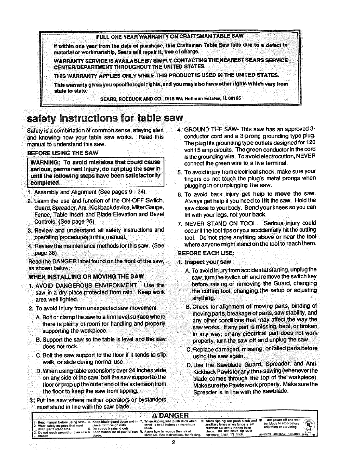
safety instructions for table saw
Safety isa combination of common sense, staying alert
and knowing how your table saw works. Read this
manual to understand this saw.
BEFORE USING THE SAW
|WARNING: To avoid roistakes that could cause I
"_serious, permanent injury, do not plug the saw in !
|until the following steps have been sat|sfactorily
I completed.
1. Assembly and Alignment (See pages 9- 24).
2. Learn the use and function of the ON-OFF Switch,
Guard, Spreader,Anti-Kickback device, MiterGauge,
Fence Table Insert and Blade Elevation and Bevel
Controls. (See page 25)
3 Review and understand all safety instructions and
operating procedures inthis manual.
4. Review the maintenance methods forthis saw. (See
page 38)
Read the DANGER label found on the front of the saw,
as shown below.
WHEN iNSTALLiNG OR MOVING THE SAW
4. GROUND THE SAW- This saw has an approved 3-
conductor cord and a 3-pror_j grounding type plug.
The plugfits grounding type outlets designed for 120
volt 15 amp cimuits. The green conductor inthe cord
isthe grounding wire. To avoid electrocution, NEVER
connect the green wire to alive terminal.
5. To avoid injury from electrical shock, make sure your
fingers do not touch the plug's metal prongs when
pluggingin or unplugging the saw.
6. To avoid back injury get help to move the saw.
Always get help if you need to lift the saw. Hold the
saw close to your body. Bend your knees so you can
liftwith your legs, not your back.
7. NEVER STAND ON TOOL. Serious injury could
occur ifthe tool tipsor you accidentally hitthe cutting
tool. Do not store anything above or near the tool
where anyone might stand on the tool to reach them.
BEFORE EACH USE:
1. inspect your saw
A. To avoid injurytrom accidental starting, unplugthe
1. AVOID DANGEROUS ENVIRONMENT. Use the
saw in a dry place protected from rain. Keep work
area well lighted.
B. Support the saw so the table is level and the saw
does not rock.
C. Bolt the saw support to the floor if it tends to slip
walk, or slide during normal use.
D. When using table extensions over 24 inches wide
on any side of the saw, belt the saw supporttothe
flooror propupthe outer end of the extension from
the flcorto keep the saw fromtipping.
3. Put the saw where neither operators orbystanders
must stand in line with the saw blade.
Spreader is in line with the sawblade,
DANGER ..... T_..... .o.o._ tl
I
I" set ace for hrou h cuts fence is set 2 inches or more from au_ ary f_rlce v/heR fence S set ;or D!_O p _lore
2, Wear safety goggles that m p g "_-'"or servi i_UL;
5DO _ot do fre_:ha_d cuts Oracle I_etwee;_ 2 and 2 riches f o_ ad ustmg _rig. _
AN_ Z87.t standards .... cuts _ _v ,
und or over saw 5 Kee henclsoutofpathofsaw 8. Knowhow Or_aducetheriskot bla(fe. DO not make rip --J
3. Do not reach _ro P.... OOORpM 130_, =-23_1_"
_ad_s blade, kickback. See instructlor_s for rtpp=ng, narrower than 1/2 _nch. _o v_=_= =_-._.-. ,=_ ,_ _pH
2
E. REMOVE ADJUSTING KEYS AND WRENCHES.
Form habit of checking for and removing keys and
adjusting wrenches from tool before turning it on.
F. To avoid injury from jams, slips or thrown pieces
(kickback and throwback):
1. USE ONLY"Recommended Accessories" (See
page 40). Follow the instructionsthat come with
the accessories. Using other accessories may
be dangerous.
2. Choose the right blade or cutting accessory for
the material and the type of cutting you plan to
do.
3. Never use grinding wheels, abrasive cut-off
wheels, friction wheels (metal slilting blades)
wirewheelsorbuffingwheel. Theycan fly apad
explosively.
4. Choose and inspect your cutting tool carefully.
a. To avoid cutting tool failure and thrown
shrapnel (broken pieces of blade), use only
10" or smaller blades sr other cutting tools
marked for speeds of 5000 rpm or higher.
b. Always use unbroken, balanced blades de-
signed to fit this saw's 5/8 inch arbor.
c. When thru-sawing (making cuts where the
blade comes through the workpiece top),
always use a10 inch diameter blade. This
keeps the spreader closest to the blade.
d. Do not overtighten arbor nut. Use arbor
wrenches to "snug" it securely.
e. Use only sharp bladeswith properly set teeth.
Consult a professional blade sharpener
when in doubt.
f. Keep blades clean of gum and resin.
5. Adjust table inserts flush with the table top.
NEVER use the saw without the proper insert.
6. Make sure all clamps and locks are tight and no
parts have any excessive play.
2. Keep work area clean
A. Cluttered areas and benches invite accidents.
Floor must not be slippery from wax or sawdust.
B. To avoid burns or other fire damage, never use the
saw near flammable liquids, vapors or gases.
C. To avoid injury,don't do layout, assembly, or setup
work on the table while the blads is spinning. It
could cut or throw anything hitting the blade.
PLAN AHEAD TO PROTECT YOUR EYES,
HANDS, FACE, EARS.
3. Plan your work
A. USE THE RIGHT TOOL -Don't force tool or
attachment to do a job it was notdesigned for.
1. DO notwear loose clothing, gloves, neckties or
jewelry (rings, wristwatches). They can get
caught and draw you into moving pads.
2. Wear nonslip footwear.
3. Tie back long hair.
4. Rol! long sleeves above the elbow.
5. Noise levels vary widely. To avoid possible
hearing damage, wear ear plugs or muffs when
using saw for long periods of time.
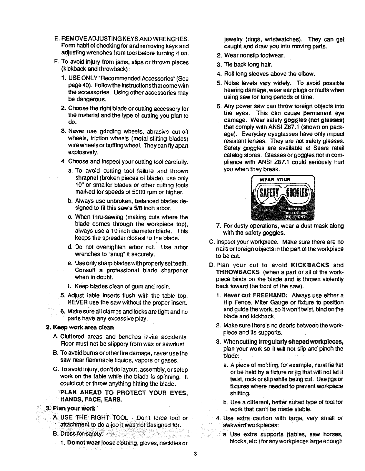
6. Any power saw can throw foreign objects into
the eyes. This can cause permanent eye
damage. Wear safety goggles (not glasses)
that comply with ANSI Z87.f (shown on pack-
age). Everyday eyeglasses have only impact
resistant lenses. They are not safety glasses.
Safety goggtes are available at Sears retail
catalog stores. Glasses or goggles not in com-
pliance with ANSI Z87.1 could seriously hurt
you when they break.
WEAR YOUR
C,
D.
7. For dusty operations, wear a dust mask along
with the safety goggles.
Inspect your workpiece. Make sure there are no
nails or foreign objects inthe part of the workpiece
to be cut.
Plan your cut to avoid KICKBACKS and
THROWBACKS (when a part or all of the work-
piece binds on the blade and is thrown violently
back toward the front of the saw).
1. Never cut FREEHAND: Always use either a
Rip Fence, Miter Gauge or fixture to position
and guide the work, so it won't twist, bind on the
blade and kickback.
2. Make sure there's no debris between the work-
piece and its supports.
3. Whencutting Irreguladyshaped workpleces,
plan your work so it will not slip and pinch the
blade:
a. A piece of molding, for example, rr_st lie flat
or be held by afixture or jig that will not let it
twist, rock or slipwhile being cut. Usejigsor
fixtures where needed to prevent workpiece
shifting.
b, Use adifferent, better suited type of tool for
work that can't be made stable.
4. Use extra caution with large, very small or
awkward workpieces:
a. Use extra supports (tables, saw horses,
blocks, etc.)for anyworkpieces large enough
uselength stopsagainst it. it must be freeto
move. If confined, itcouldget wedged against
the blade and cause a kickback or throw-
back.
c. Never cut more than one workpiece at a time.
d. Never turn your table saw"ON" before clear-
ing everything except the workpiece and
related support devices off the table.
4. Planthewayyouwlil pushtheworkplecethrough
3. Set the cutting tool as low as possible for the cut
you're planning.
4. KEEP CHILDREN AWAY. All visitors should be kept
asafe distance fromwork. Make sure bystanders are
clear of the saw and workpiece.
5. Let the blade reach full speed before cutting.
6. DON'T FORCE TOOL. It will do the job better and
safer atitsdesignedrate. Feedtheworkpiece intothe
blade only fast enough to let it cut without bogging
down or binding.
7. Before freeing any jammed material:
A. Turn switch "OFF".
A. NEVER pull the workplece through. Start and B. Unplug the saw.
finish the cut from the front of the table saw,
B. NEVER put your fingers or hands in the path of
the sawb ade or other cutting tool.
C. NEVER reach !n back of the cuttingtool with either
hand to hold down or support the workpiece
remove wood scraps, or for any other reason,
D. Avoid hand positions where a sudden slip could
cause fingers or hand to move into asawblade or
other cutting tool.
C. Wait for all moving parts to stop.
D. Check blade, Spreader and Fence for proper align-
ment before starting, again.
8, To avoid throwback of cut off pieces;
A. Use the Guard assembly.
B. To remove loose pieces beneath or trapped inside
the guard:
1. Turn saw "OFF".
2. Remove switch key.
3. Wait forblade to stop before lifting the Guard,
F. Push the workpiece against the rotation of the
blade. NEVER feed material into the cutting tool
from the rear of the saw.
G_Always push the workpiece all the way past the
sawblade.
H. As much as possible, keep your face and body to
one side of the sawblade, outer line with a possible
kickback or throwback.
I. NEVER tum the saw "ON"before clearing the table
of all tools wood scraps, etc., except the work-
piece and related feed or support devices forthe
cut planned.
J. AVOID ACCIDENTAL STARTING - Make sure
switch is"OFF" before plugging saw in,
WHENEVER SAW BLADE IS SPINNING
I WARNING: Don't let familiarity (gained from fre-_
quent use of your table saw) cause a careless j
1mistake, Always remember that a careless frac- J
tlon of a second Is enough to cause a severe j
Iinjury. J
t. Before actually cutting with the saw, watch it while it
runs for a short while. If it makes an unfamiliar noise
ADDITIONAL INSTRUCTIONS FOR
RiP TYPE CUTS
1. NEVER use the Miter Gauge when ripping.
2. Use aPush Stick whenever the fence is 2 or more
inches from the blade. When thru-sawing, use an
Auxiliary Fence and Push Block wheneverthe Fence
mustbe between 112and2 inchesofthe blade. Never
thru-saw rip cuts narrower than 1t2 inch. (See "Basic
Saw Operation -Using the Rip Fence" section.)
3. Never rip anything shorter than 10" long.
4. When using a Push Stick or PuSh Block, the trailing
end of the board must be square. APush Stick or
Blockagainst an uneven end could slipoff or push the
work away from the Fence.
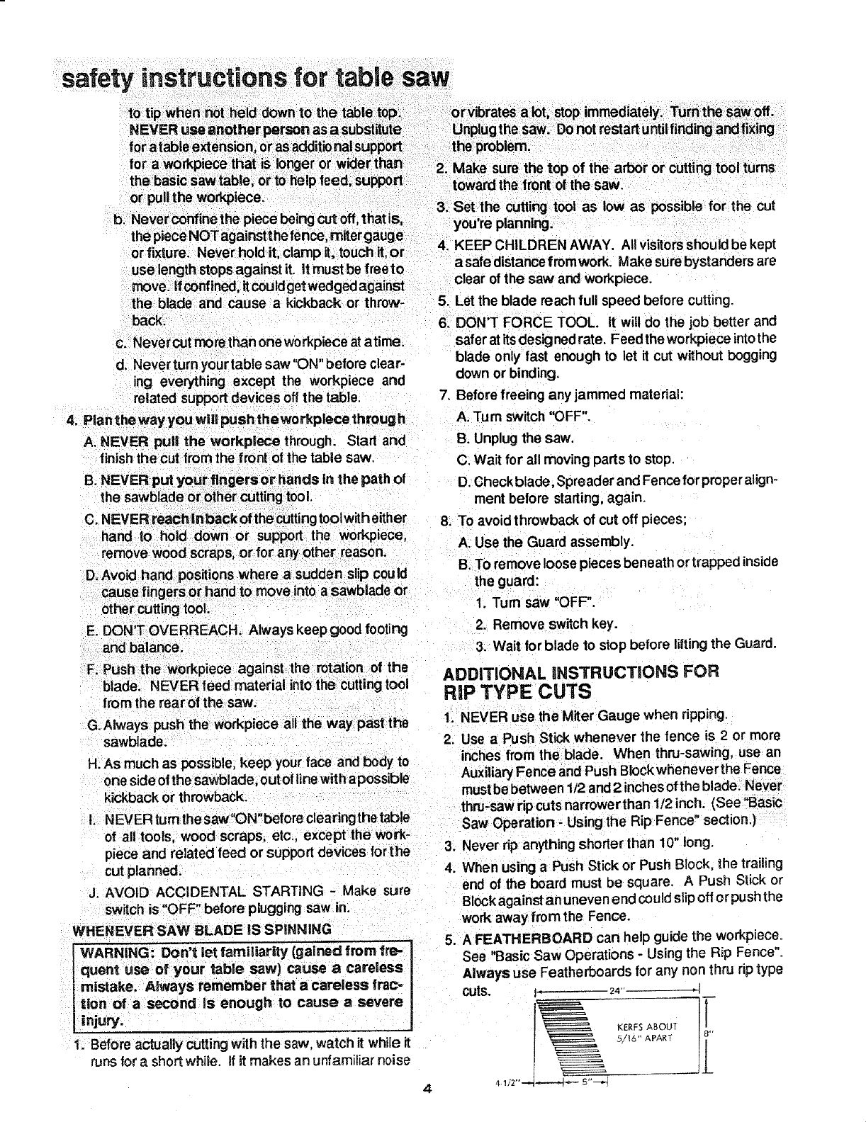
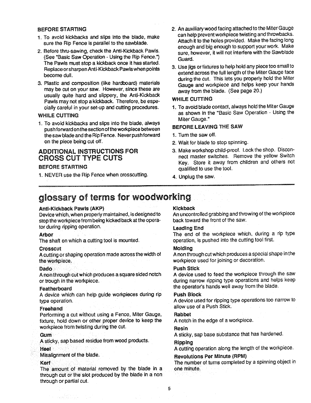
5. A FEATHEABOARD can help guide the workpiece.
See "Basic Saw Operations - Using the Rip Fence".
Always use Featherboards for any non thru rip type
CUTS. I' 24" _1
KERFS ABOUT
I_ 5/16" APART I"
1 JL
4.112""--_-=-----_J 5"_,-_
BEFORE STARTING
1. To avoid kickbacks and slips into the blade, make
sure the Rip Fence is parallel to the sawblade.
2. Before thru-sawing, check the Anti-Kickback Pawls.
(See "Basic Saw Operation - Using the Rip Fence.")
The Pawls must stop a kickback once it has started.
Replace or sharpen Anti-Kickback Pawiswhen points
become dull.
3. Plastic and composition (like hardboard) materials
may be cut on your saw. However, since these are
usually quite hard and slippery, the Anti-Kickback
Pawls may not stop a kickback. Therefore, be espe-
cially careful in your set-up and cutting procedures.
WHILE CUTTING
1. TO avoid kickbacks and slips into the blade, always
push forwardon the sectionof the workpiece between
the saw blade and the Rip Fence, Never pushforward
on the piece being cut off.
ADDITIONAL iNSTRUCTiONS FOR
CROSS CUT TYPE CUTS
BEFORE STARTING
1. NEVER use the Rip Fence when crosscutting.
2. An auxiliary wood facing attached to the Miter Gauge
can help prevent workpiece twisting and throwbacks.
Attach it tothe holes provided. Make the facing !ong
enough and big enough to support your work. Make
sure, however, it will not interfere with the Sawbiade
Guard.
3. Use jigs or fixtures to help hold any piece too small to
extend across the full length of the Miter Gauge face
during the cut. This lets you properly hold the Miter
Gauge and workpiece and helps keep your hands
away from the blade. (See page 20.)
WHILE CUTTING
1. To avoid blade contact, always hold the Miter Gauge
as shown in the "Basic Saw Operation - Using the
Miter Gauge."
BEFORE LEAVING THE SAY#
1. Turn the saw off.
2. Wait for blade to stop spinning.
3. Make workshop child-proof. Lockthe shop. Discon-
nect master switches. Remove the yellow Switch
Key. Store it away from children and others not
qualified to use the tool.
4. Unplug the saw.
gmossary of terms for woodworking
Anti-Kickback Pawls (AKP)
Device which, when properly maintained, isdesigned to
stop the workpiece from being kicked back at the opera-
tor during ripping operation,
Arbor
The shaft on which a cutting tool is mounted.
Crosscut
A cuttingor shaping operation made acrossthe width of
theworkpiece.
Dadc
A non through cut which produces a square sided notch
or trough in the workpiece.
Featherboard
A device which can help guide workpieces during rip
type operation.
Freehand
Performing acut without using a Fence, Miter Gauge,
fixture, hold down or other proper device to keep the
workpiece from twisting during the cut
Gum
Asticky, sap based residue from wood products.
Heel
Misalignment of the blade.
Kerr
The amount of matedat removed by the blade in a
through cut or the slot produced by the blade in anon
through or partial cut.
Kickback
An uncontrolled grabbing and throwing of the workpiece
back toward the front of the saw.
Leading End
The end of the workpiece which, during a rip type
operation, is pushed into the cutting tool first.
Molding
Anon through cut which produces a special shape inthe
workpiece used for joining or decoration.
Push Stick
Adevice used to feed the workpiece through the saw
during narrow ripping type operations and helps keep
the operator's hands well away from the blade.
Push Block
Adevice used for ripping type operation_ too narrow to
allow use of a Push Stick.
Rabbet
Anotch in the edge of a workpiece.
Resin
Asticky, sap base substance that has hardened.
Ripping
Acutting operation along the length of the workpiece.
Revolutions Per Minute (RPM)
The number of turns completed by a spinning object in
one minute.

glossary of terms for woodworking
h
thepart of the workDiece which will be. or has been_cut
by the blade. Trail End
Set , the =n anpping
The distance thai [ne up oi [ne sawo_aoe _oo_n_soem to r
set) outward from the face of the blade. Workpiece
Throw-Back The item on which the cutting operation is being done.
are commonly referred to
specifications:
Voltage ............................................................... 120
Amperes .............................................................. 13
Hertz ................................................. i.................. 60
Phase ........................................................... Single
RPM ......................... 5000
Rotation (viewed from
\
GROUNDING PRONG
UNDED
3-PRONG OUTLET
WARNING: Electricshock can kill. Not all outlets
are property grounded. If you are not sure that
youroutlet is properly grounded, have it checked
by a qualified electrician.
WARNING: Toavoid electrical shock, do not
permit fingers totouch the terminals of the plug,
when installing or removing the plug to or from
the outlet.
I WARNING: Failureto properly groundthis power 1
tool can cause electrocution or serious shock,
particularly when used indamp locations, or near
metal plumbing, if shocked, your reaction could
cause your hands to hit the cutting tool.
This saw is equipped with a 3-conductor cord and
grounding type plug which has been approved by Un-
derwriters' Laboratories. The ground conductor has a
greenjacket and is attached to the tool housing at one
end andtothe ground prong in the attachment plug atthe
other end.
This saw must be grounded while in use to protect the This plug requires a mating 3-conductor grounding type
operatorfrom electrical shock.
Your saw iswired for 120 volts and it has a plug that looks
like the one shown.
Plug power cord into a 110-120V properly grounded
typeoutlet protected by a 15 amp. time delay or Circuit-
Saver fuse or circuit breaker.
3utlet as shown,
WARNING: Avoid electric Shock. If the outlet you
are planning to use for this saw is of the two prong
type, DO NOT REMOVE OR ALTER THE
GROUNDING PRONG IN ANY MANNER. Use
an adapter, as shown, and always connect the
grounding lug to aknown ground.
2. Although the motor is designed for operation on. the
voltage and frequency spec lied on motor nameplate,
minimal loads will be handled safely at voltages 10%
above or below the nameplate voltage. Heavy loads,
however, require that voltage at the motor be the
voltage specified on nameplate.
3. Most motor troubles may be traced to loose or incor:
rectconnections overloading reduced input voltage
(which results when small size wires are used inthe
supply circuit) or when the supply circuitis extremely
long. Always check connection, load and suppl,/
circuit when the motor fails to perform satisfactorily.
Check wire sizes and lengthswithtable at endof this
section.
CONNECTING TO POWER SOURCE
OUTLET
sawblade end) ......................... Counterclockwise WARNING: Damaged power cords can cause
MOTOR SAFETY PROTECTION shock or fires, if the power cord is worn, cut, or
damaged in any way, have it replaced immedi-
1. Frequent opening of fuses or circuit breakers may ately.
result il motor is overloaded or if the motor circuitis .
GROUNDING LUG
PLUG i_ _KNOWN GROUND
-_ RECEPTACLE
ADAPTER
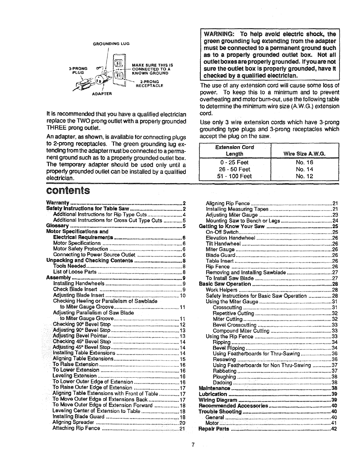
It is recommended that you have aqualified electrician
replace the TWO prong outlet with aproperly grounded
THREE prong outlet.
An adapter, as shown, is available for connecting pgugs
to 2-prong receptacles. The green grounding lug ex-
tending from the adapter must be connected to a perma-
nent ground such as to a properly grounded outlet box.
The temporary adapter should be used only until a
propedy grounded outlet can be installed by a qualified
electrician.
contents
WARNING: To help avoid electric Shock, the
green grounding lug extending from the adapter
must be connected tOapermanent ground such
as to aproperly grounded outlet box. Not all
outlet boxes are properly grounded, if you are not
sure the outlet box is properly grounded, have H
checked by aqualified electrlclano
The use of any extension cord will cause some loss of
power. To keep this to a minimum and to prevent
overheating and motor burn-out, use the foflowing table
to determine the minimum wire size (A.W.G.) extension
cord.
Use only 3 wire extension cords which have 3-prong
grounding type plugs and 3-prong receptacles which
accept the plug on the saw.
F._ension Cord
Length Wire Size A.W.G.
0 - 25 Feet No. 16
26 - 50 Feet No. 14
51 - 100 Feet No. 12
Warranty ............................................................................. 2
Safety Instructions for Table Saw .................................... 2
Additional Instructions for Rip Type Cuts ........................ 4
Additional Instructions fGr Cross Cut Type Cuts ............. 5
Glossary ............................................................................. 5
Motor Specifications and
Electrical Requirements ............................................... 6
Motor Specifications ....................................................... 6
Motor Safety Protection .................................................. 6
Connecting to Power Source Outlet ............................... 6
Unpacking and Checking Contents ................................. 8
Tools Needed .................................................................. 8
List of Loose Parts .......................................................... 8
Assembly ............................................................................ 9
Installing Handwheels ..................................................... 9
Check Blade Insert ......................................................... 9
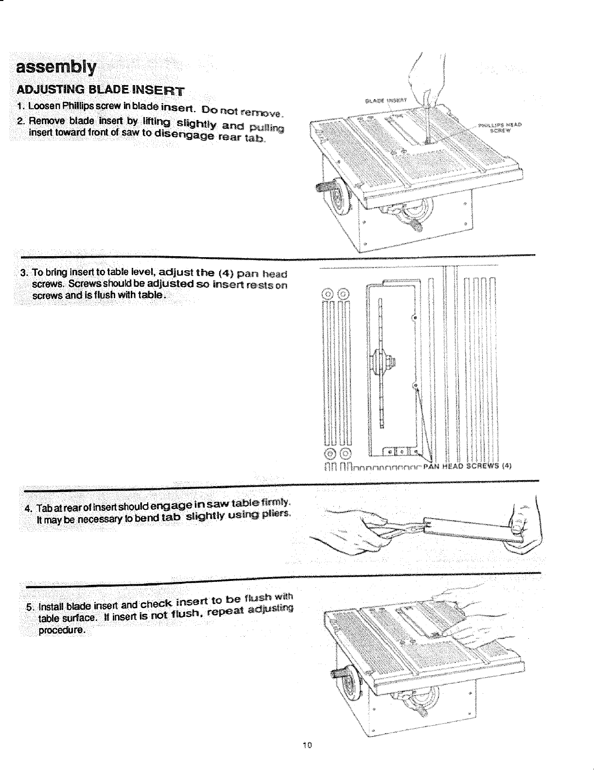
Adjusting Blade insert ................................................... 10
Checking Heeling or Parallelism of Sawblade
to Miter Gauge Groove ............................................. 11
Adjusting Parallelism of Saw Blade
to Miter Gauge Groove ............................................. 11
Checking 90= Bevel Stop ............................................. 12
Adjusting 90° Bevel Stop ............................................... 13
Adjusting Bevel Pointer ................................................. 13
Checking 45° Bevel Stop .............................................. 14
Adjusting 45°Bevel Stop ............................................... 14
Installing Table Extensions ........................................... 14
Aligning Table Extensions ............................................. 15
To Raise Extension ....................................................... 16
To Lower Extension ...................................................... 16
Leveling Extension ....................................................... 16
To Lower Outer Edge of Extension ............................... 16
To Raise Outer Edge of Extension ............................... 17
Aligning Table Extensions with Front of Table .............. 17
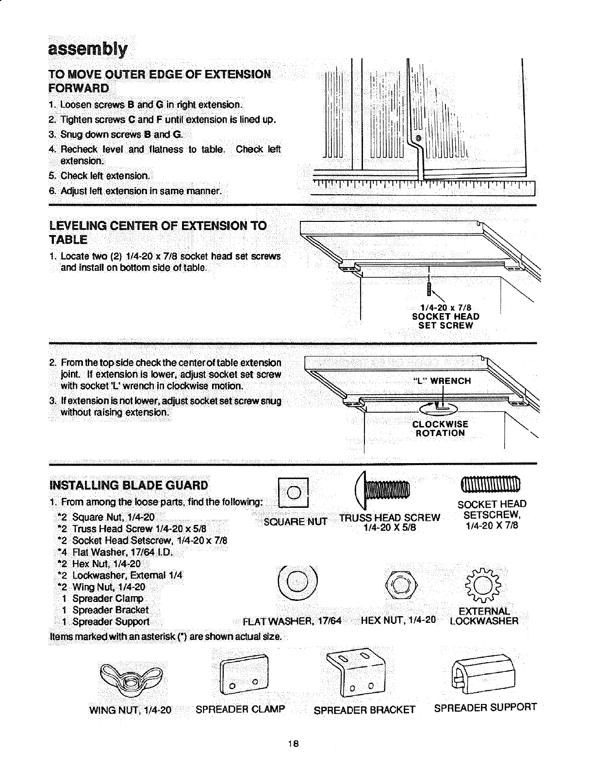
To Move Outer Edge of Extensions Back ..................... 17
To Move Outer Edge of Extension Forward ................. 18
Leveling Center of Extension to Table .......................... 18
Installing Blade Guard .................................................. 1B
Aligning Spreader ......................................................... 20
Attaching Rip Fence ..................................................... 21
Aligning Rip Fence ........................................................ 21
Installing Measuring Tapes ........................................... 2t
Adjusting M_ter Gauge .................................................. 23
Mounting Saw to Bench or Legs ................................... 24
Getting to Know Your Saw ............................................. 25
On-Off Switch ................................................................ 25
Elevation Handwheel .................................................... 26
Tilt Handwheel .............................................................. 26
Miter Gauge .................................................................. 26
Blade Guard .................................................................. 26
Table Insert ................................................................... 26
Rip Fence .................................................................... 26
Removing and installing Sawblade ............................... 27
To install Saw Blade ..................................................... 27
Basic Saw Operation ....................................................... 28
Work Helpers ................................................................ 28
Safety Instructions for Basic Saw Operation ................ 28
Using the Miter Gauge .................................................. 31
Crosscutting ............................................................. 31
Repetitive Cutting ..................................................... 32
Miter Cutting ............................................................. 32
Bevel Crosscutting ................................................... 33
Compound Miter Cutting .......................................... 33
Using the Rip Fence ..................................................... 33
Ripping ..................................................................... 34
Bevel Ripping ........................................................... 34
Using Featherboards for Thru-Sawing ..................... 36
Resawing ................................................................. 36
Using Featherboards for Non Thru-Sawing ............. 37
Rabbeting ................................................................. 37
Ploughing ................................................................. 38
Dadoing .................................................................... 38
Maintenance ..................................................................... 38
Lubdcartion ...................................................................... 39
Wiring Diagram ................................................................ 39
Recommended Accessories .......................................... 40
Trouble Shooting ............................................................ 40
General ......................................................................... 40
Motor .............................................................................. 41
Repair Parts .................................................................... 42
Medium Screwdriver 7/16, 1/2,11/16 in.
#2 Phi ips Screwdriver ._ Long Nose P ers
"J' _ ""h P ers
Hex 'L 'wrenc
, 3/lf6, I/8, 5/32 in.
Combination Square
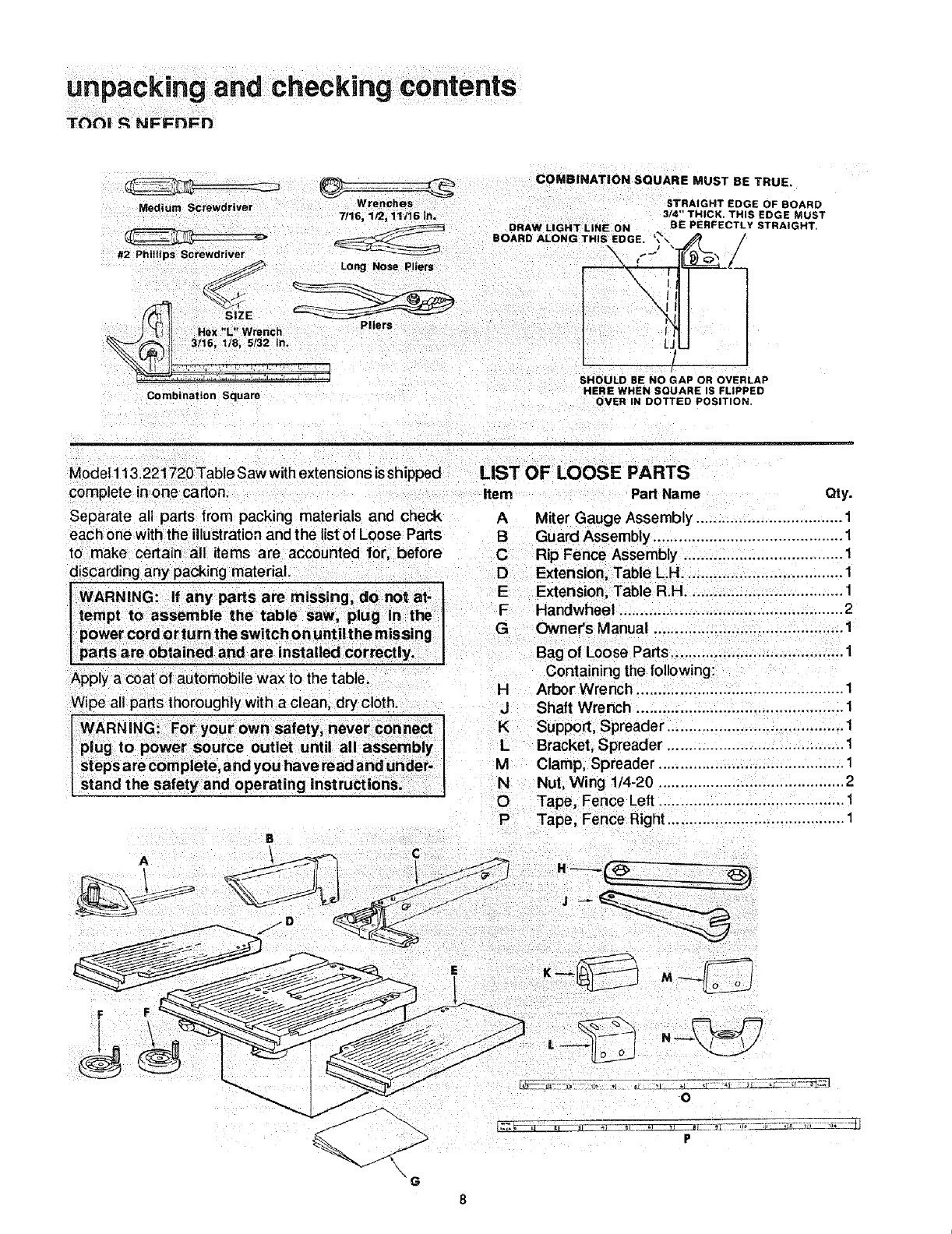
COMBINATION SQUARE MUST BE TRUE.
DRAW LIGHT LINE ON %BE PERFECTLY
BOARD ALONG THIS EDGE, ',, \ ,_ /
I
x.,ll11
SHOULD BE NO GAP OR OVERLAP
HERE WHEN SQUARE JS FLIPPED
OVER IN DOTTED POSITION,
STRAIGHT EDGE OF BOARD
3/4" THICK. THIS EDGE MUST
STRAIGHT,
Model 113.221720 Table Saw withextensions is shipped
complete inone carton.
Separate all parts from packing materials and check
each one with the illustrationand the list of Loose Parts
to make certain all items are accounted for, before
discarding any packing material.
t WARNING: If any parts are missing, do not at-
I tempt to assemble the table saw, plug in the ]
power cord or turn the switch on until the missing I
parts are obtained and are installed correctly. I
LIST OF LOOSE PARTS
Item Part Name Qty.
A Miter Gauge Assembly .................................. 1
B Guard Assembly ............................................ 1
C Rip Fence Assembly ..................................... 1
D Extension, Table LH ..................................... 1
E Extension, Table R.H .................................... 1
F Handwheel .................................................... 2
GOwner's Manual ............................................ 1
Bag of Loose Parts ....................................... 1
Apply a coat of automobile wax to the table.
Wipe all parts thoroughly with a clean, dry cloth.
WARNING: For your own safety, never connect
plug to power source outlet until all assembly t
steps are complete, and you have read and under
stand the safety and operating instructions. I
Containing the following:
HArbor Wrench ................... 1
J Shaft Wrench ................................................ 1
K Support, Spreader ......................................... 1
L Bracket, Spreader ......................................... 1
M Clamp, Spreader ........................................... 1
N Nut, Wing 1/4-20 ........................................... 2
O Tape, Fence Left ........................................... 1
P Tape, Fence Right ......................................... 1
A
N
o
P
assembly
Bag of Loose Parts
Containing the following:
Q Key, Switch ................................................... 1
R Nut, Square 1/4-20 ........................................ 2
S Screw, Soc. Set 1/4x 7/8 ........................ ...... 4
TWasher, Flat 17/64 x 9/16 x 3/64 .................. 4
U Lockwasher, External 1/4 .............................. 4
U Lockwasher, External #8 ............................... 2
V Nut, Hex 1/4-20 ............................................. 2
W Screw, Truss Hd. 1/4-20 x 5/8 ....................... 2
X Screw, Pan Hd. 8-32 x 3/8 ............................ 2
Y Screw, Flat Hd. 1/4-20 x 5/8 ........................ 14
_Q V
%w
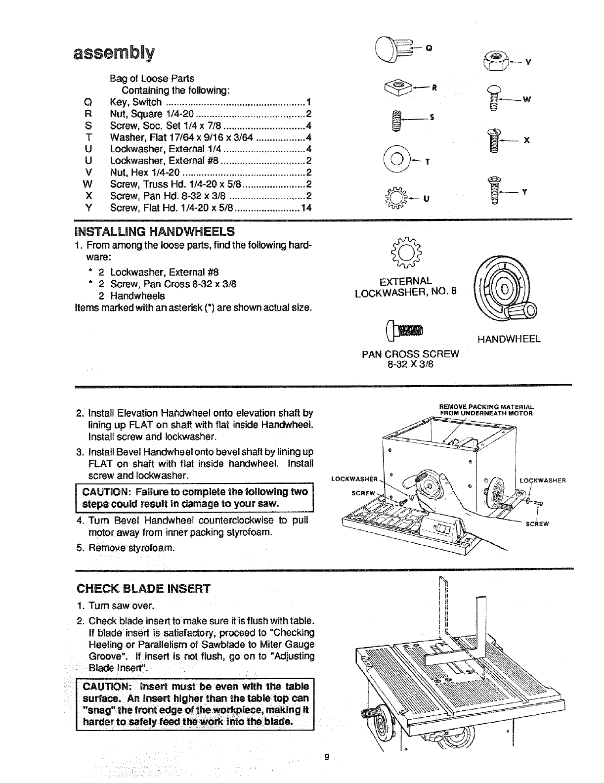
mNSTALUNG HANDWHEELS
1. From among the loose parts, find the following hard-
ware:
* 2 Lockwasher, External #8
*2Screw, Pan Cross 8-32 x 3/8
2 Handwheels
Items marked with an asterisk (*) are shown actual size.
EXTERNAL
LOCKWASHER, NO. 8
PAN CROSS SCREW
8-32 X 3/8
HANDWHEEL
2. install Elevation Hahdwheel onto elevation shaft by
lining up FLAT on shaft with flat inside Handwheel.
install screw and Iockwasher.
3. install Bevel Handwheelonto bevel shaft by lining up
FLAT on shaft with fiat inside handwheel, install
screw and Iockwasher.
CAUTION: Failure to complete the foflowing two
steps could result _ndamage to your saw.
4. Turn Bevel Handwheel counterclockwise to pull
motor away from inner packing styrofoam.
5. Remove styrofoam.
LOCKWASHER.
REMOVEPACKING MATERIAL
FROM UNDERNEATH MOTOR
LOCKWASHER
SCREW
CHECK BLADE INSERT
1. rum saw over.
2. Check blade insert to make sure it is flush with table.
If blade insert is satisfactory, proceed to "Checking
Heeling or Parallelism of Sawbiade to Miter Gauge
Groove". If insert is not flush, go on to "Adjusting
Blade Insert".
CAUTION: insert must be even with the table J
surface. An insert higher than the table top can I
"snag" the front edge of the workpiece, making it
harder to safely feed the work into the blade.
I II
TI
ge in saw table t_y.
bsligl_ly using pi_rs
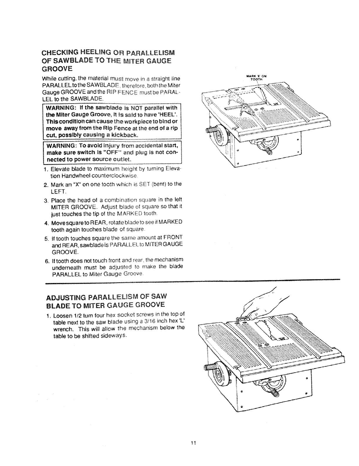
CHECKING HEELING OR PARALLELISM
OF SAWBLADE TO THE ?4_TER GAUGE
GROOVE
Whi_e cutting, the materia_ must _:_e _ _ _Vai_h__
PARALLEL to the SAWBLADE there,'o_e_t;<_thtr_eMi_er
Gauge GROOVE and the R_P F_NCE m_Jstbe PARAL_
LEL to the SAWBLADE.
WARNING: If the sawb_ade _s NOT para_let w_th
the Miter Gauge Groove, _ _s _td _ohave _HEEL',
This cond fUon can cau_ the wo_kp_ce to b_nd o_"
move away from the Rip Fence _ th4_er_dof 8 rip
cut, possibly causing ak_¢kback.
WARNING: To avoid Injury _rom acc_n_al start,
make sure switch Is "OFF" and p_ug is not corn
nected to power source ou_et,
1. Elevate blade to ma×imum t_e _h_by tumi{_g E_eva_
t_onHandwheel counte_cbc:kwis_
2, Mark an "X" on ore _ooth which i_ SE!t (beret)to _he
LEFT.
3. Place the head of acomb Rat;o# sq_;_re {n _he _t
MITER GROOVE. Adjust b_e ol squsre so _hat i_
just touches the tip of the MAnKinD V._oth.
4. Movesquareto REAR, rotate bi_detosee # MARKED
tooth again touches blade of sqL_are.
5. if tooth touches square the s_me a_:_ur_tat FRONT
and REAR, sawb_adeis PAR AL.LEL,_oM_ER GAUGE
GROOVE.
6. If tooth does not touch fro_t and rear _hem_han_sm
underneath must be adiusted _o make #_e b_ade
PARALLEL to M_ter Gauge G#oove.
ADJUSTING PARALLELISM OF SAW
BLADE TO MITER GAUGE GROOVE
1, Loosen 1/2 turn _our hex socket screws ir_the _opof
table next to the saw blade #si#.g _ 37t6 ir_chhex 'L'
wrench, This "will allow the rr_chanism betow _he
labie to be sh_fted sideways.
M_RK "x o_
T_3OTN
\
\\\
if It does -alternately tighten other three screws
slowly.
\
12
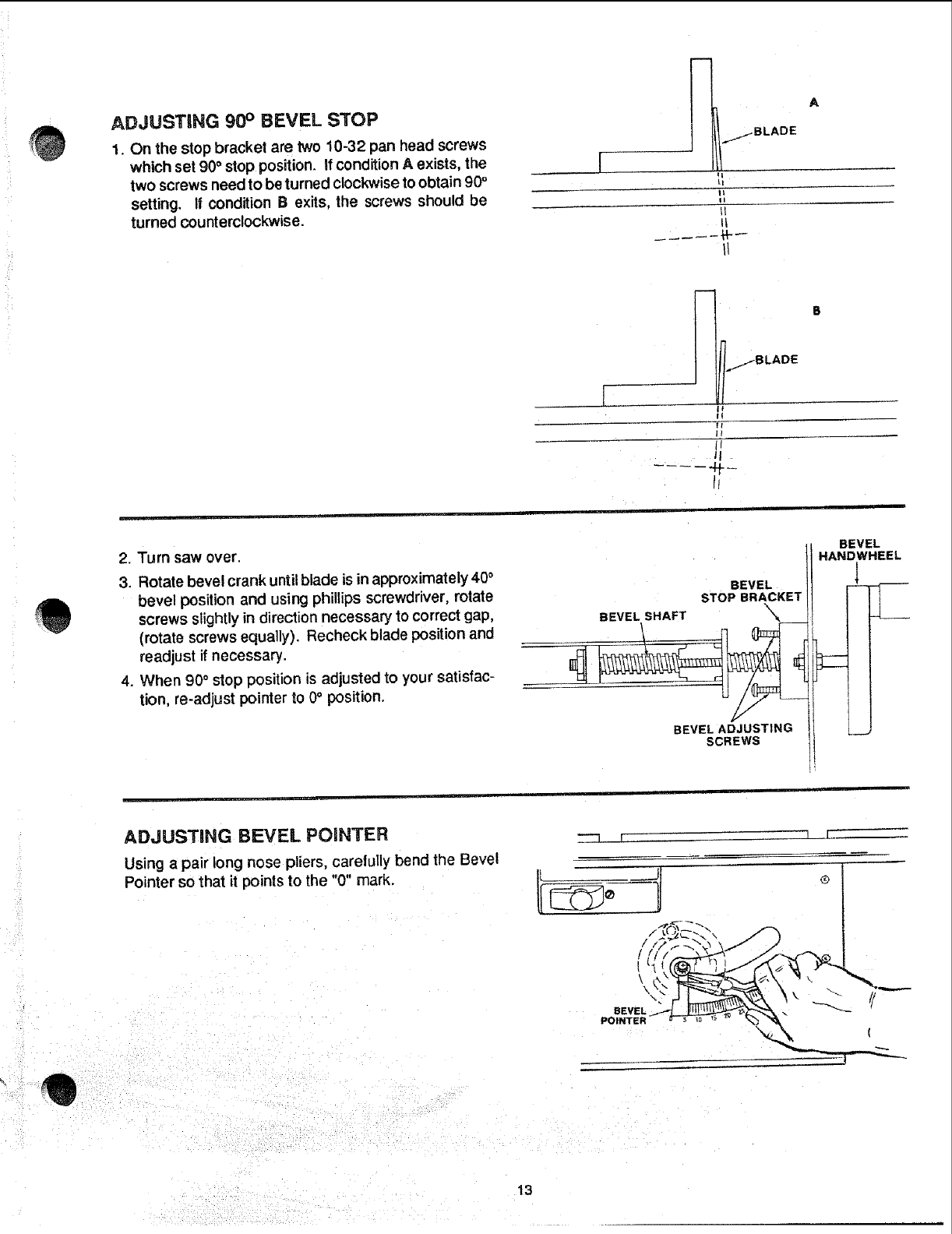
ADJUSTING 90 ° BEVEL STOP
1. On the stop bracket are two 10-32 pan head screws
which set 90°stop position. If condition A exists, the
two screws need to be turned clockwise to obtain 90=
setting. If condition B exits, the screws should be
turned counterclockwise.
/BLADE
_t
tl
It
II
2. Turn saw over.
3. Rotate bevel crank until blade is in approximately 40°
bevel position and using phillips screwdriver, rotate
screws slightly in direction necessary to correct gap,
(rotate screws equally). Recheck blade position and
readjust if necessary.
4. When 90° stop position is adjusted to your satisfac-
tion, re-adjust pointer to 0° position.
/BLADE
II
I
I I
Ir
ti
BEVEL
STOP BRACKET
BEVEL .A T \
BEVEL ADJUSTING
SCREWS
BEVEL
HANDWHEEL
1
....... ! _
ADJUSTING BEVEL POINTER
Using a pair long nose pliers, carefully bend the Bevel
Pointer so that it points to the "0" mark.
_---3 fr
I
®
I
13
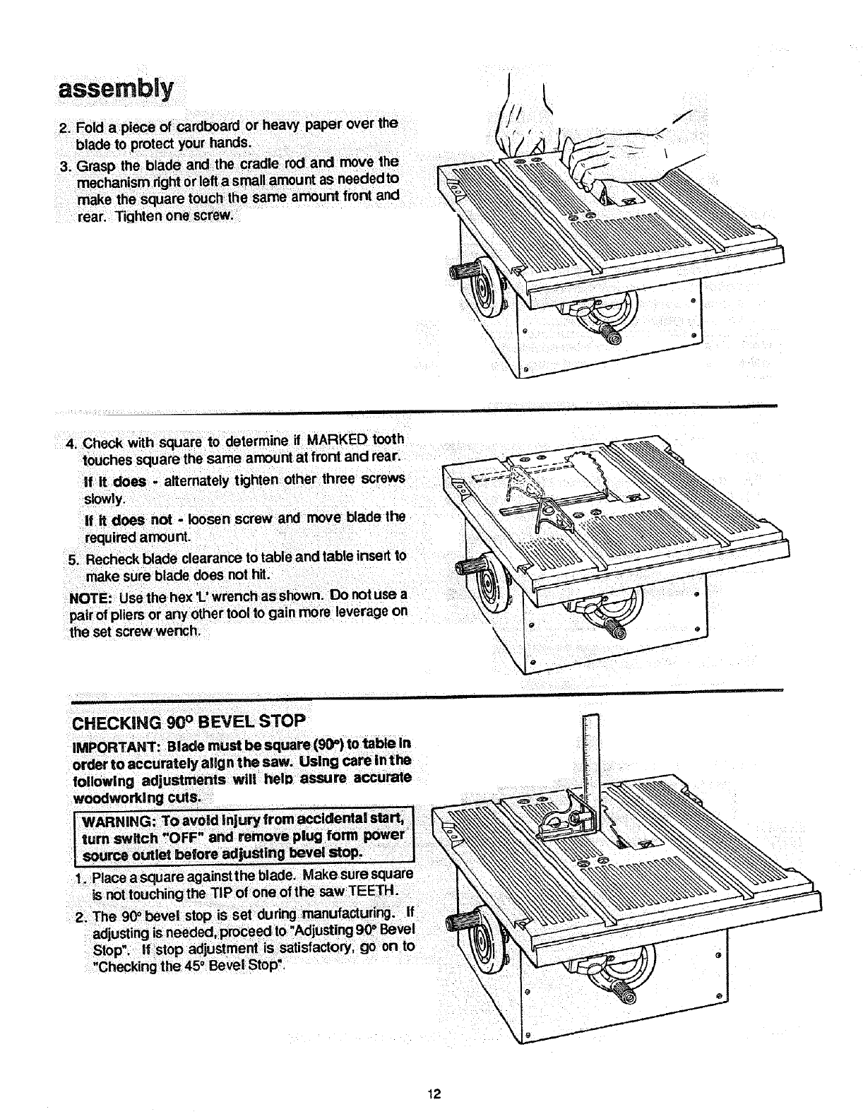
assembly
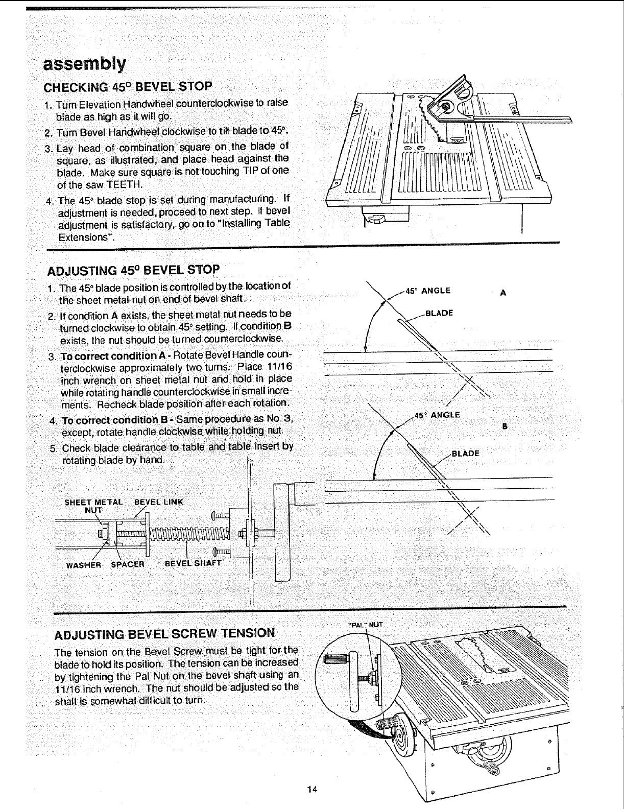
CHECKING 45° BEVEL STOP
1. Turn Elevation Handwhee counterc ockwise to raise
blade as high as it will go.
2. Turn Bevel Handwheel clockwise to tilt blade to 45_.
3. Lay head of combination square on the blade of
square, as ustrated, and place head against the
blade. Make sure square is not touching TIP of one
of the saw TEETH.
4. The 45oblade stop is set during manufacturing. If
adjustment s needed, proceed to next step. If bevel
adjustment is satisfactory, go on to" nstalling Tab e
Extensions".
ADJUSTING 45 ° B EVEL STOP
1. The 450blade position iscontrolled by the locationof
the sheet metal nut on end of bevel shaft.
2. If condition A exists, the sheet metal nutneeds to be
turned clockwise to obtain 45° setting_ if condition B
exists, the nut should be turned counterclockwise,
3. To correct conditionA -Rotate Bevel Handle coun-
terc ockw se approximately two turns. Place 11/16
inch wrench on sheet meta nut and hold nplace
while rotatinghandle counterclockwise insmall incre-
ments, Recheck blade positionaftereach rotation.
X°ANGLE
/ILADE
\\
J
jBLADE
E
\\ \\
/
/"
ADJUSTING BEVEL SCREW TENSION
The tension on the Beve Screw must be tight for then ['_J_
by tightening the Pa Nut on the bevel shaft using a |
11/16 inch wrench. The nut should be adjusted so the
shaft is somewhat difficult to turn. k
14
"PAL" NUT
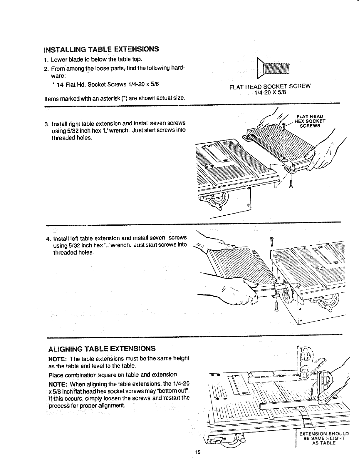
iNSTALLiNG TABLE EXTENSIONS
1. Lower blade to below the table top.
2. From among the loose parts, find the following hard-
ware:
*14 Flat Hd. Socket Screws 1/4-20 x 5/8
Items marked with an asterisk {*) are shown actual size.
i
FLAT HEAD SOCKET SCREW
1/4-20 X 5/8
i
3. Install right table extension and installseven screws
using 5/32 inch hex 'L' wrench. Just start screws into
threaded holes.
FLAT HEAD
HEXSOCKET
SCREWS
4. Install left table extension and install seven screws
using 5/32 inch hex 'L'wrench, Just start screws into
threaded holes.
\
ALiGNiNG TABLE EXTENSIONS
NOTE: The table extensions must be the same height
as the table and level to the table.
Place combination square on table and extension.
NOTE: When aligning the table extensions, the 1/4-20
x 5/8 inchflat head hex socket screws may "bottomout".
If this occurs, simply loosen the screws and restart the
process for proper alignment.
15
EXTENSION SHOULD
BE SAME HEIGHT
AS TABLE
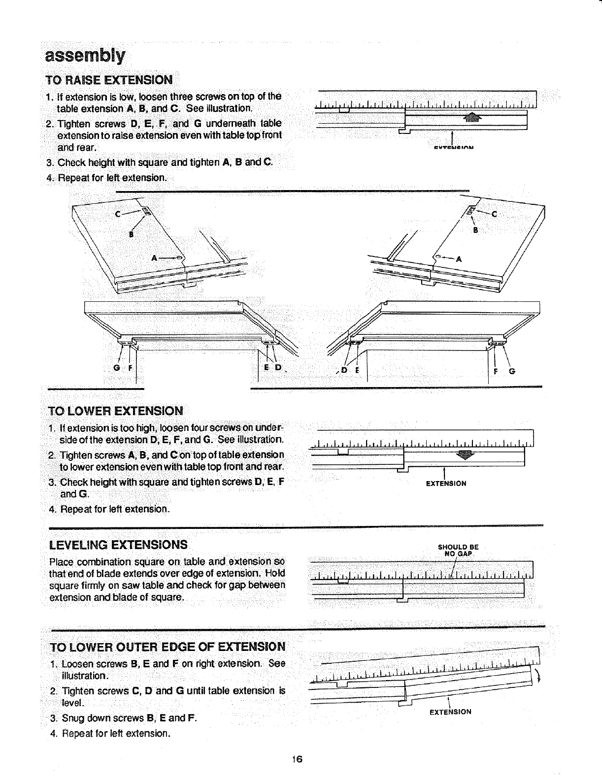
TO RAISE EXTENSION
and rear.
3. Check height with square and tighten A B and C.
4. Repeat for left extension.
i
a=vTl_l @ar_DJ
TO LOWER EXTENSION
2_ Tighten screws A, B, and C on top of table extension
to lower extension even with table top front and rear.
3. Check height with square and tighten screws D, E, F
and G.
4. Repeat for lelt extension.
,I ,Jll,l.l.', l,i.I.=,l..l,t.l.l,l.i.l,l,l.J,l,w, I,i ,I,[,]
EXTENSION
LEVELING EXTENSIONS
Place combination square on table and extension so
that end of blade extendsover edge of extension. Hold
square firmly on saw table and check for gap between
extension and btade of square.
SHOULD BE
NO GAP
TO LOWER OUTER EDGE OF EXTENSION
1. Loosen screws B, E and F on right extension. See
illustration.
2. Tighten screws C, D and G until table extension is
leve!.....
3_ Snug down screws B, E and F.
4. Repeat for left extension.
EXTENSION
16
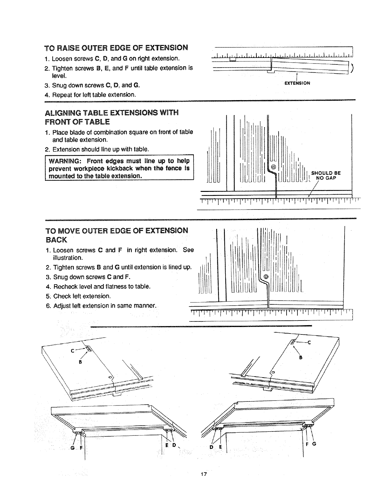
TO RAISE OUTER EDGE OF EXTENSION
1. Loosen screws C, D, and G on right extension.
2. Tighten screws B, E, and F until table extension is
level.
3. Snug down screws C, D, and G.
4. Repeat for left table extension.
, ,,, ,
L..._J ------
ALiGNiNG TABLE EXTENSIONS W_TH
FRONT OF TABLE
1. Place blade of combination square on front of table
and table extension.
2. Extension should line up with tabie.
WARNING: Front edges must line up to help
prevent workplece kickback when the fence is
mounted to the table extension.
t
EXTENSION
SHOULD BE
INO GAP
TO MOVE OUTER EDGE OF EXTENSION
BACK
1 Loosen screws Cand F in right extension. See
illustration.
2. Tighten screws Band G until extension is lined up.
3. Snug down screws Cand F.
4. Recheck level and flatness to table,
5, Check left extension.
6. Adjust left extension in same manner, --q
J
\\\
/\
/s
/
17
extension.
5. Check left extension.
6. Adjust left extension in same manner.
Check left
!I,
i:li i '! |
ill |1
!!t |_
H
I
iili llil,
•ii1,1 ii
I I I I III I t t tl't'l'l'='l'J'l'l'l'l'l'l'l 'j' I
LEVELING CENTER OF EXTENSION 3"0
TABLE
1. Locatetwo (2) 1/4-20 x 7/8 socketheadsetscrews
andinstallon bottomsideoftable. I
I
t\
1/4-20 x 7/8
SOCKET HEAD
SET SCREW
joir
with "L" WRENCH
CLOCKWISE
ROTATION
INSTALLING BLADE GUARD
1, From among the loose parts, find the following:
,i
SOCKET HEAD
TRUSS HEAD SCREW SETSCREW,
1!4-20 X5/8 1/4-20 X 7/8
*4 Flat Washer, 17/64 I.D.
FLAT WASHER, 17164
Items marked with an asterisk (_) are shown actual size.
WING NUT, 1/4-20 SPREADER CLAMP
©
HEX NUT, 1/4-20
i
SPREADER BRACKET
EXTERNAL
LOCKWASHER
SPREADER SUPPORT
18
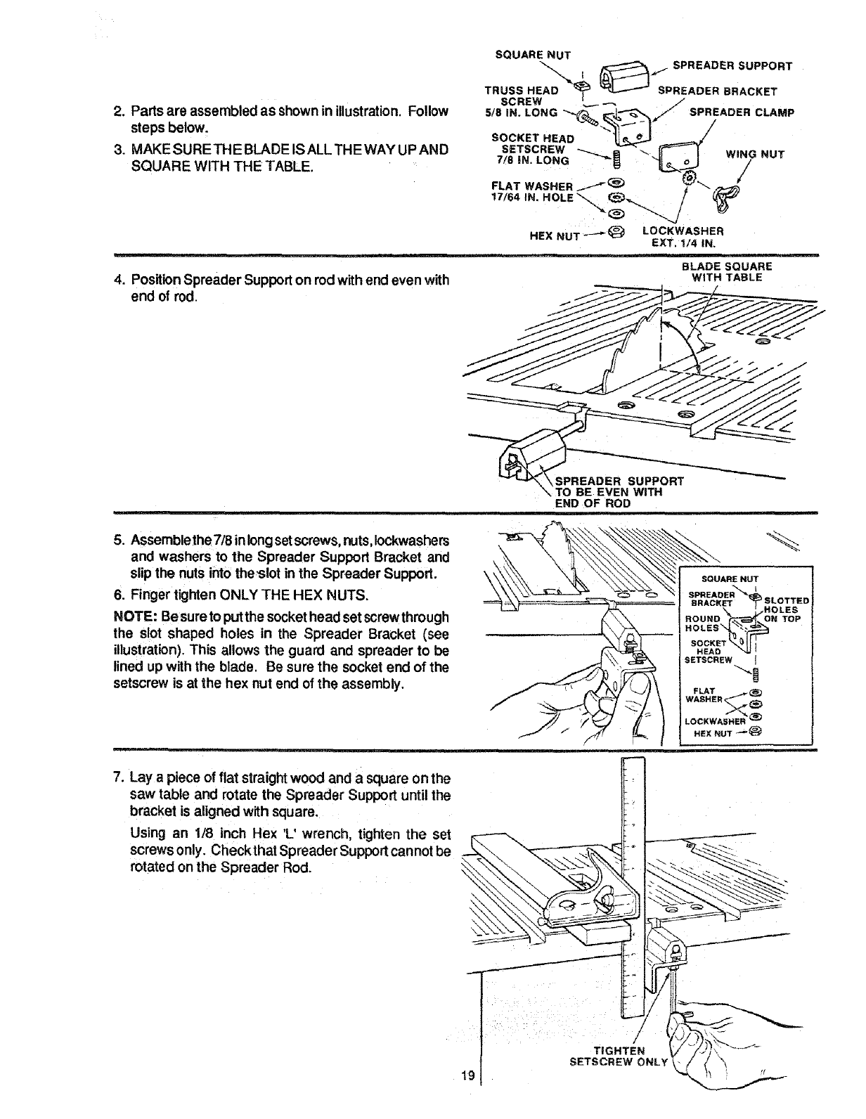
2. Parts are assembled as shown in illustration. Follow
steps below.
3. MAKE SURE TH E BLADE IS ALL THE WAY UP AND
SQUARE WITH THE TABLE.
SQUARE NUT
_..,_ , _=./ SPREADER SUPPORT
TRUSS HEAD _, _ SPREADER BRACKET
SCREW I
5/8 IN. LONG _"__/_ _ SPREADER CLAMP
SOCKETHEAD _ _'/
SETSCREW _---__ 8 "_, _ I WING NUT
7/8 iN. LONG "'_ "_o_J /,
wAS.E.tt
HEX NuT "-"_ _LOCKWASHER
EXT. 1/4 IN.
BLADE SQUARE
4. Position Spreader Support on rod with end even with
end of rod.
WITH TABLE
"O BE EVEN WiTH
END OF ROD
5. Assemble the7/8 inlongsetscrews, nuts,iockwashers
and washers to the Spreader Support Bracket and
slip the nuts into theslot in the Spreader Support.
6. Finger tighten ONLY THE HEX NUTS.
NOTE: Be sureto put the socket head set screwthrough
the slot shaped holes in the Spreader Bracket (see
illustration). This allows the guard and spreader to be
lined up with the blade. Be sure the socket end of the
setscrew is at the hex nut end of the assembly.
HEAD
SETSCREW "m
FLAT
WASHER _
LOCKWASHER _
HEX NUT _
,.Layap,eoeo,,, s,ra,0ht.o an a__oo,ho
saw table and rotate the Spreader Support until the
bracket is aligned with square,
Using an 1/8 inch Hex 'L' wrench, tighten the set °
screws only. Check that Spreader Support cannot be
rotated on the Spreader Rod.
/
TIGHTEN
SETSCREW ONLY
!9
/
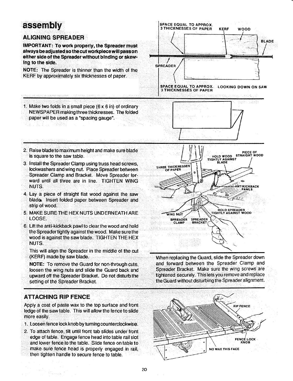
ALIGNING SPREADER
IMPORTANT: To work properly, the Spreader must
lways be adj usted so t he cut wo rkpiece w ill pass on
ither side of the Spreader without binding or skew- _==
s
SPACE EQUAL TO APPROX,
3 THICKNESSES OF PAPER KERF WOOD
=.. _ -....
SPACE EQUAL TO APPROX. LOOKING DOWN ON SAW
3 THICKNESSES OF PAPER
1 Make two folds in a small piece (6 x 6 n) of ordinary
NEWSPAPER making three thicknesses. The folded
paper will be used as a "spacing gauge".
/
/
2. Raise blade to maximum height and make sure blade
is square to the saw table.
3. Install the Spreader Clamp using truss head screws,
Iockwashers and wing nut. Place Spreader between T,BEEoFTHICKNESSESpAPER
PIECE OF
HOLD WOOD STRAIGHT WOOD
TIGHTLYBLADEAGAINST /
4. Lay a piece of straight flat wood against the saw
blade_ Insert folded paper between Spreader and
stripof wood.
5; MAKE SURETHEHEX NUTS UNDERNEATH ARE
LOOSE.
6, Lift the anti-kickback pawl to clear the wood and hold
the Spreader tightly against the wood. Make surethe
wood is against the saw blade. TIGHTEN THE HEX
NUTS.
This will alignthe Spreader in the middle of the cut
{KERF) madeby saw blade.
NOTE: To remove the Guard for non-throughcuts,
ATTACHING RiP FENCE
more easily,
1, Loosen fence Iockknob by turningcountemlockwise,
2, To attach fence, tilt untilfront tab slides under front
edge of table, Engage fence head into table rail slot
and lower fencetothe table. Slide fence on table to
make sure fence head is properly engaged in rail,
then tighten handle to secure fence to table.
HOLD SPREADER
TIGHTLY AGAINST WOOD
/
SPREADER SPREADER
CLAMP BRACKET
_
When replacing the Guard, slide the Spreader down
and forward between the Spreader Clamp and
Spreader Bracket. Make sure the wing screws are
tightened securely. This lets you remove and replace
the Guard withoutdisturbing the Spreader alignment.
i
FENCE
FENCE LOCK
KNOB
NO WAX THiS FACE
2O
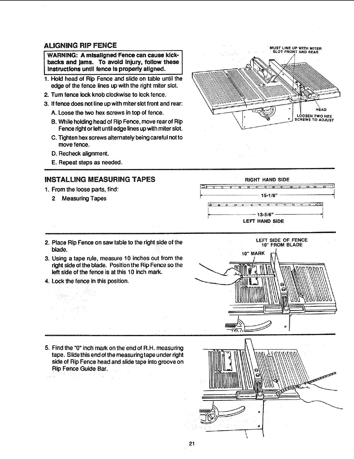
ALiGNiNG RiP FENCE
WARNING: A mlsailgned Fence can cause kick-
backs and jams. To avoid injury, follow these
instructions until fence is properly aligned.
1. Hold head of Rip Fence and slide on table until the
edge of the fence lines up with the right miter slot.
2. Turn fence lock knob clockwise to lock fence.
3. if fence does notline up with miter slotfront and rear;
A. Loose the two hex screws in top of fence.
B. While holdinghead of Rip Fence, move rear of Rip
Fence rightorleft untiledge lines upwith miter slot.
C. Tighten hex screws alternately beingcareful notto
move fence.
D. Recheck alignment.
E. Repeat steps as needed.
MUST LINE UP WITH MITER
SLOT FRONT AND REAR
HEAD
LOOSEN TWO HEX
SCREWS TO ADJUST
iNSTALLiNG MEASURING TAPES
1. From the loose pads, find:
2 Measuring Tapes
RIGHT HAND SiDE
ls-l!s" t
t ..... t
LEFT HAND SIDE
2. Place Rip Fence on saw table to the rightside of the
blade.
3. Using atape rule, measure 10 inches out from the
right side of the blade. Positionthe Rip Fence so the
left side of the fence is at this 10 inch mark.
4. Lock the fence in this position.
LEFT SiDE OF FENCE
10" FROM BLADE
10" MARK
5. Find the "0" inch mark on the end of R.H. measuring
tape. Slide this end ofthe measuring tape under right
side of Rip Fence head and slide tape intogroove on
Rip Fence Guide Bar.
21
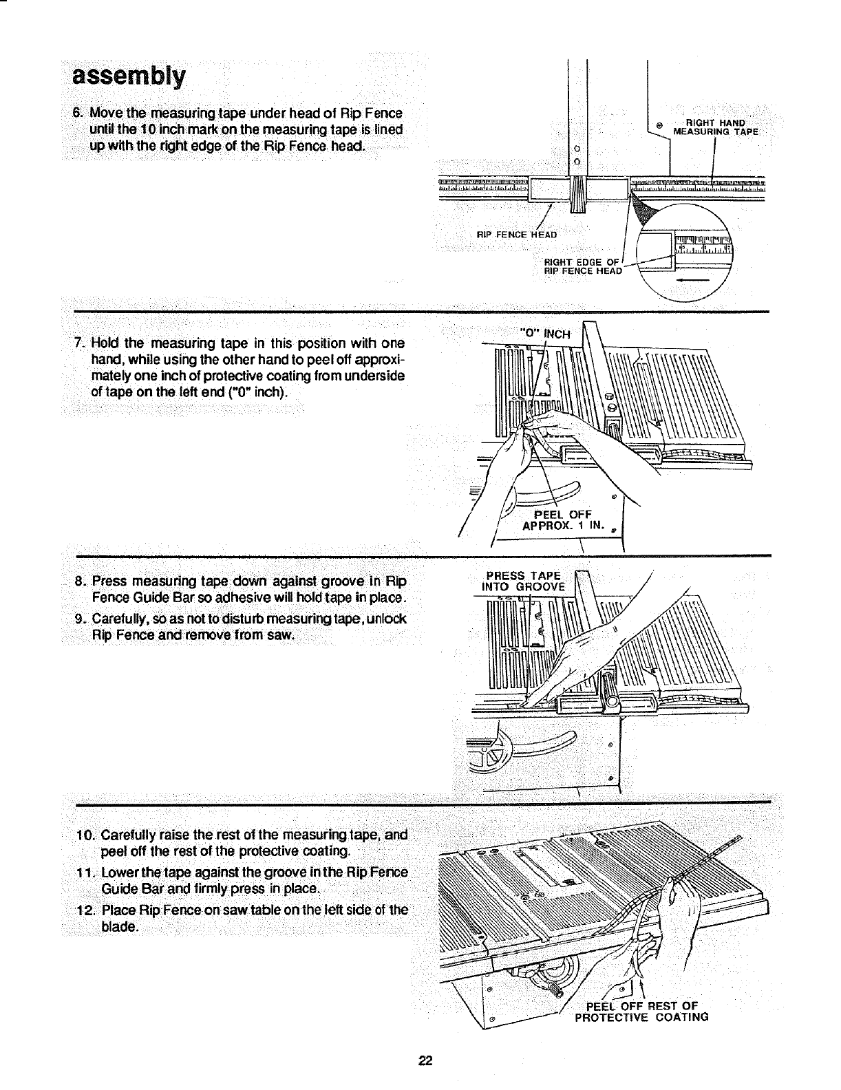
6. Move the measuring tape under head of Rip Fence
untilthe 10 inch mark on the measuring tape is lined
up with the right edge of the Rip Fence head.
RiP FENCE H__
\ 11
7_ Hold the measuring tape in this position with one
hand, while using the other hand to peel off approxi-
mately one inch of protective coating from underside
of tape on the left end ("0" inch).
"O" INCH
9. Carefully, so as notto disturb measuring tape, unlock
Rip Fence and remove from saw.
PEEL OFF X_
rAPPROX. 1 IN.
/\
PRESS TAPE
INTO
10. Carefully raise the rest of the measuring tape, and
peel off the rest of the protective coating.
12. Place Rip Fence on saw table on the left side of the
blade.
REST OF
COATING
22
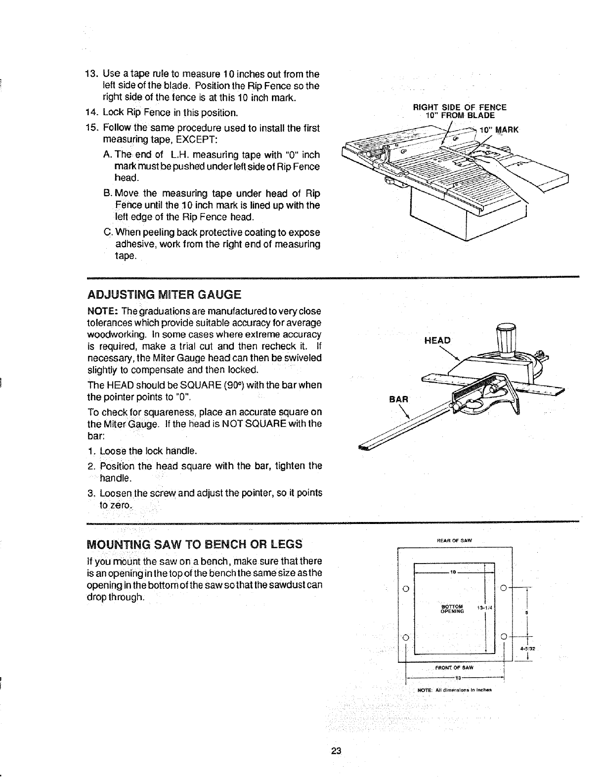
13. Use a tape rule to measure 10 inches out from the
left side of the blade. Position the Rip Fence so the
right side of the fence is at this 10 inch mark.
14. Lock Rip Fence in this position.
15. Follow the same procedure used to install the first
measuring tape, EXCEPT:
A. The end of L.H. measuring tape with "0" inch
mark must be pushed under left side of Rip Fence
head.
B. Move the measuring tape under head of Rip
Fence untit the t0 inch mark is lined up with the
left edge of the Rip Fence head.
C. When peeling back protective coating to expose
adhesive, work from the right end of measuring
tape.
RIGHT SiDE OF FENCE
10" FROM BLADE
MARK
ADJUSTING MITER GAUGE
NOTE: The graduations are manufactured to very close
tolerances which provide suitable accuracyfor average
woodworking. In some cases where extreme accuracy
is required, make a trial cut and then recheck it. If
necessary, the Miter Gauge head can then be swiveled
slightly to compensate and then locked.
The HEAD should be SQUARE (90°) withthe bar when
the pointer points to "0".
To check for squareness, place an accurate square on
the Miter Gauge. If the head is NOT SQUARE with the
bar:
1. Loose the lock handle.
2. Position the head square with the bar, tighten the
handle.
3. Loosen the screw and adjust the pointer, so it points
to zero.
MOUNTING SAW TO BENCH OR LEGS
If you mount the saw on a bench, make sure that there
is an opening inthe top of the bench the same size as the
opening inthe bottom of the saw so that the sawdust can
drop through.
REAR OF SAW
FRONT OF YAW
13-
5
1
4-5f32
_K_TE: All d_ttens_ons in Inche_
23
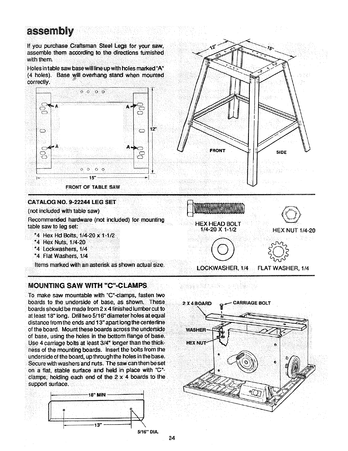
assembly
with them.
correctly.
o o 0 0
A_
0 o o 0
FRONTOF TABLESAW
P_
FRONT SIDE
CATALOG NO. 9-22244 LEG SET
(not included with table saw)
Recommended hardware (not included) for mounting
table saw to teg set:
*4 Rex Hcl Bolts, 1/4-20 x 1-1/2
items marked with an asterisk as shown actual size.
HEX HEAD BOLT
1/4-20 ×1-1/2 HEX NUT 1/4-20
©
LOCKWASHER, 1/4 FLAT WASHER, 1/4
" " MPMOUNTING SAW WITH C -CLA S
To makesaw mountablewith "C"-clamps, fasten two
underside of the board, up through the holes inthe base.
Secure withwashers and nuts. The saw can then be set
on a flat, stable surface and held in place with "G"-
I_ 18" MIN "1
5116"DIA, 24
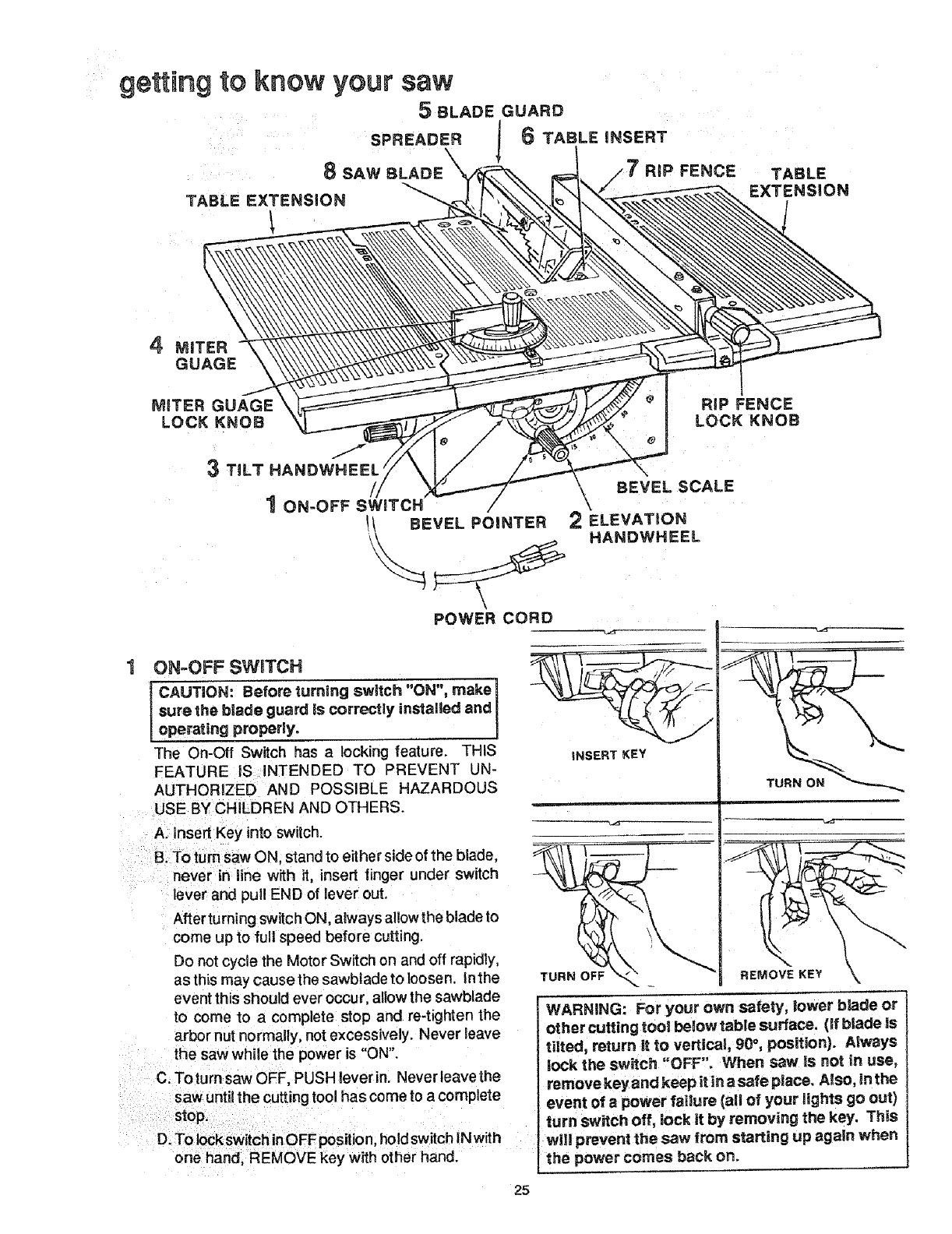
getting to know your saw
5BLADE GUARD
SPREADER 6TABLE iNSERT
RiP FENCE TABLE
EXTENSION
J
3 TiLT HANDWHEEL
BEVEL SCALE
1ON-OFF SWITCH
POWER CORD
ON-OFF SWITCH
CAUTION: Before turning switch "ON", make]
sure the blade guard is correctly installed and
operating properly. J
The On-Off Switch has a locking feature. THIS
FEATURE iS INTENDED TO PREVENT UN-
AUTHORIZED AND POSSIBLE HAZARDOUS
USE BY CHILDREN AND OTHERS.
A. insert Key into switch.
B_To turn saw ON, stand to either side of the blade,
never in line with it, insert finger under switch
lever and pull END of lever out.
After turning switch ON, a_ways allow the blade to
come up to full speed before cutting.
Do not cycle the Motor Switch on and off rapidly,
as this may causethe sawbtade to loosen, lathe
event this should ever occur, allow the sawblade
to come to a complete stop and re-tighten the
arbor nut normally, not excessively, Never leave
the saw while the power is "ON".
C. Toturn saw OFF, PUSH lever in. Never leave the
saw untit the cutting tool has come to acomplete
stop.
D. To lock switch inOFF position hold switch N with
one hand, REMOVE key wittl other hand.
TURN ON
WARNING: For your own safety, lower blade or
other cutting tool below table surface. (if blacie is
tilted, return it to vertical, 90°, position). Always
lock the switch "OFF", When sew is not in use,
remove key and keep it in a safe place. Also, in the
event of apower failure [all of your lights go out)
turn switch off, lock it by removing the key. This
wll! prevent the saw from starting up again when
the power comes back on.
25
getting to know your saw
2ELEVATION HANDWHEEL... elevates or
Iowersthe blade. Turn counterclockwise to elevate,
clockwise to lower.
3TILTHANDWHEEL...tiltsthebladeforbevel
cutting. Turn counterclockwise to tilt toward eft,
clockwise to tilttoward right.
When the blade is tited to the LEFT as far as itwill
go, it should be at 45°to the table and the bevel
indicator should point to 45°.
NOTE: There are LIMIT STOPS inside the saw
which prevent the b ade frorntiltingbeyo nd450tothe
LEFT and 90° to the RIGHT. ( See "Adjustments
section"BladeTilt,orSquarenessof Bladeto Table _.
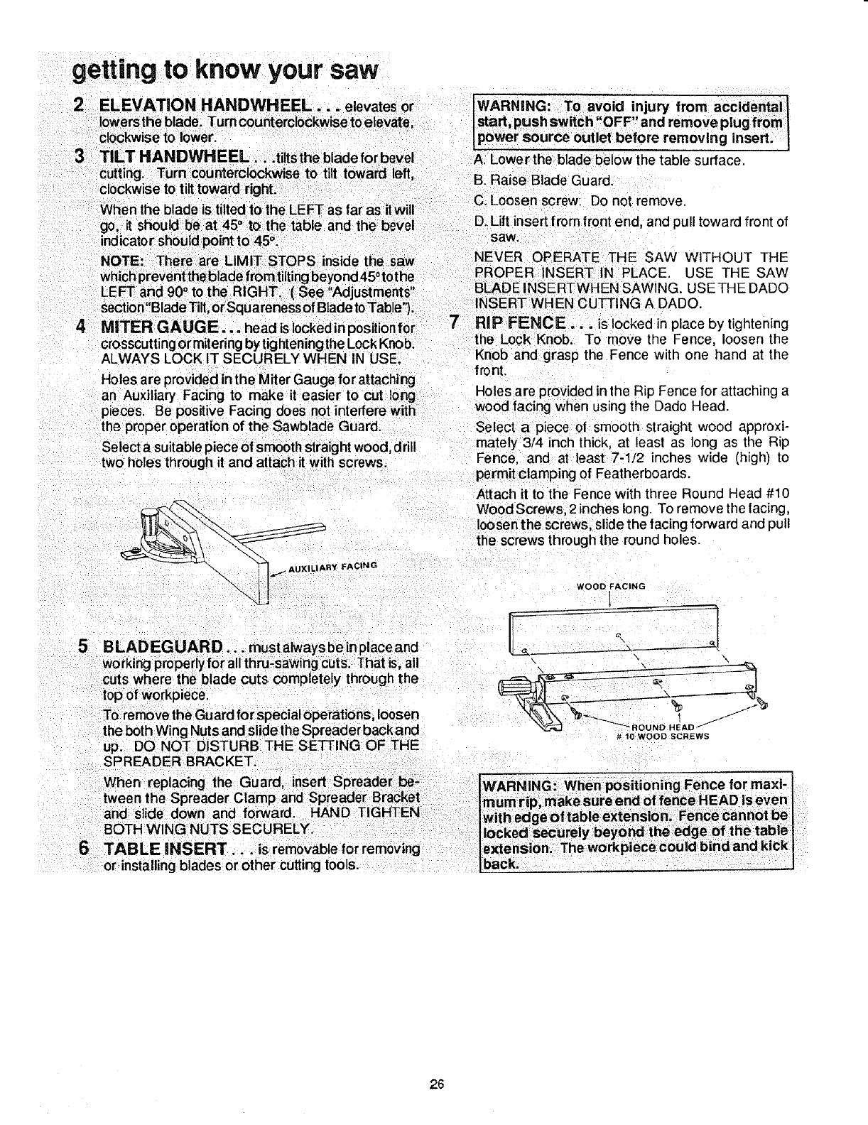
4 MITER GAUGE... headislockedinposltionfor
crosscuttingormitering by tighteningthe LockKnob.
ALWAYS LOCK IT SECURELY WHEN IN USE.
Holes are provided in the Miter Gauge for attaching
an Auxiliary Facing to make it easier to cut long
p eces. Be positive Facing does not interfere with
the proper operation of the Sawblade Guard
Select a suitable piece of smooth straight wood, drill
two holes through it and attach it with screws.
RY FACING
B LAD EG UAR D... must always be inplace and
working properly for allthru-sawing cuts. That is, all
cuts where the blade cuts completely through the
top of workpiece.
To remove the Guard for special operations, loosen
the both Wing Nuts and slide the Spreader back and
up. DO NO=FDISTURB THE SETTING OF THE
SPREADER BRACKET.
6TABLE iNSERT.., is removable for removing
or installing blades or other cutting tools.
A. Lower the blade below the table surface
B. Raise Blade Guard.
C. Loosen screw. Do not remove.
D. Lift insert from front end, and pull toward front of
saw,
NEVER OPERATE THE SAW WITHOUT THE
PROPER INSERT IN PLACE, USE THE SAW
BLADE INSERTWHEN SAWING. USETHE DADO
INSERT WHEN CUTTING A DADO.
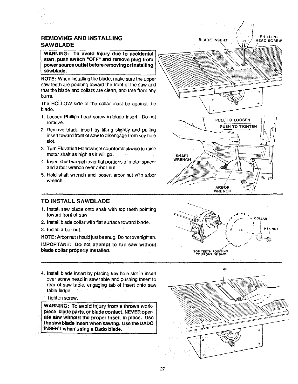
7 RiP FENCE... is locked in place by tightening
the Lock Knob. To move the Fence loosen the
Knob and grasp the Fence with one hand at the
front.
Holes are provided in the Rip Fence for attaching a
wood facing when using the Dado Head.
Select a piece of smooth straight wood approxi-
mately 3/4 inch thick, at least as long as the Rip
Fence. and at least 7-1/2 inches wide (high) to
permit clamping of Featherboards.
Attach it to the Fence with three Round Head #10
Wood Screws, 2 inches long. To remove the facing,
loosen the screws, slide the facing forward and pull
the screws through the round holes.
WOOD FACING
#10 WOOD SCREWS
IWARNING: When positioning Fence for maxi- I
mum rip, make sure end offence HEAD is even 1
with edge Of table extension. Fence cannot be I
Ilocked securely beyond the edge of the table I
lextension. The workpiece could bind and kick I
Iback. _J
26
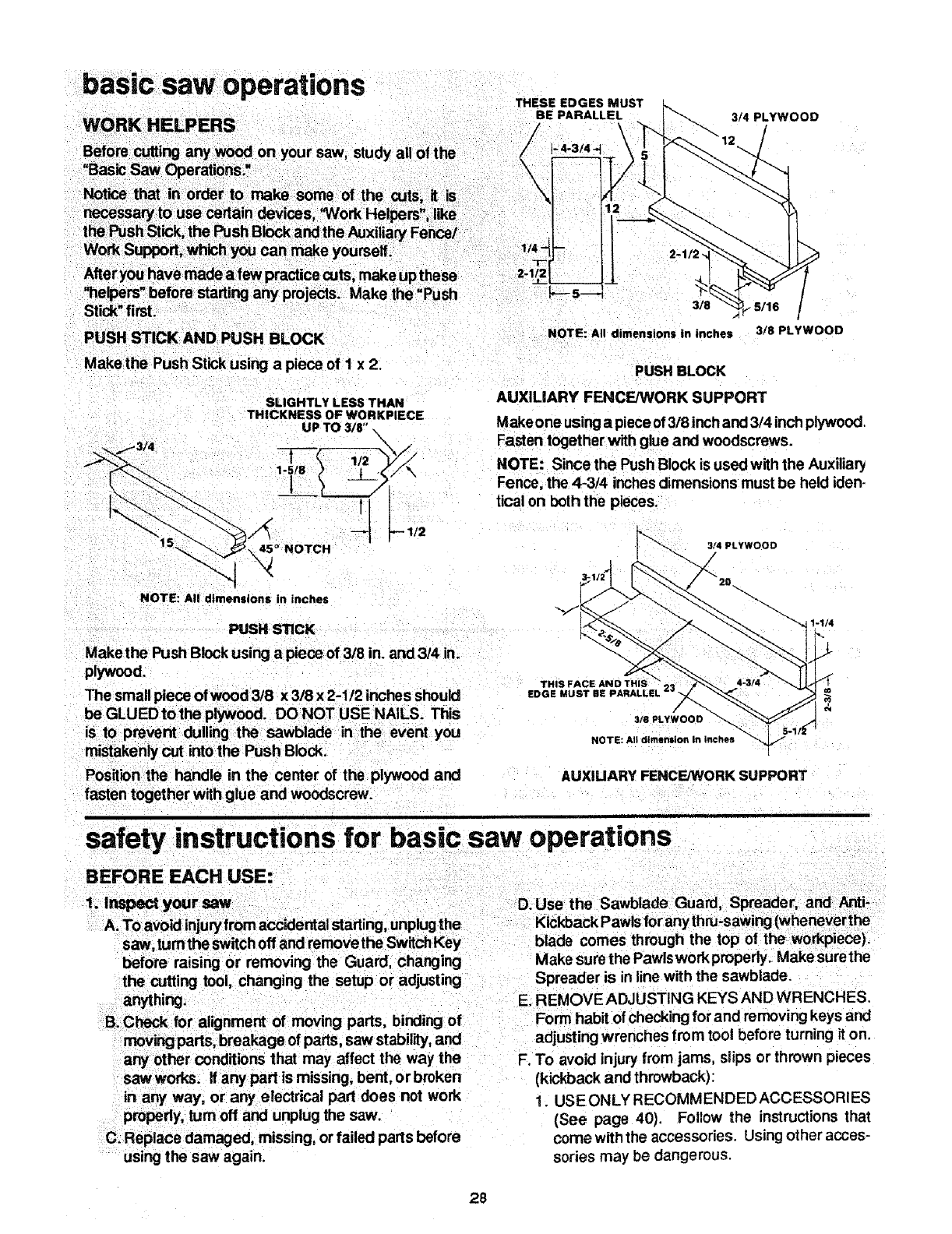
REMOVING AND iNSTALLiNG
SAWBLADE
WARNING: To avoid Injury due to accidental
start, push switch "OFF" and remove plug from
power source outlet before removing or installing
sawblade.
NOTE: When installing the blade, make sure the upper \\\_\\_
saw teeth are pointing toward the front of the saw and
that the blade and collars are clean, and free from any
burrs.
The HOLLOW side of the collar must be against the
blade.
1. Loosen Phillips head screw in blade insert, Do not
remove.
2. Remove blade insert by lifting slightly and pulling
insert toward front of saw to disengage from key hole
slot.
3. Turn Elevation Handwheel counterclockwise to raise
motor shaft as high as it will go.
4. Insert shaft wrench over flat portions of motor spacer
and arbor wrench over arbor nut.
5. Hold shaft wrench and loosen arbor nut with arbor
wrench.
SHAFT
WRENCH
BLADE INSERT
\
ARBOR
WRENCH
TO INSTALL SAWBLADE
1, Install saw blade onto shaft with top teeth pointing
toward front of saw.
2. Install blade collar with flat surface toward blade.
3. Install arbor nut.
NOTE: Arbor nutshould justbesnug. Do notovertighten,
IMPORTANT: Do not attempt to run saw without
blade collar properly installed.
2,_ /
/
TOP TEETH POINTING
TO FRONT OF SAW
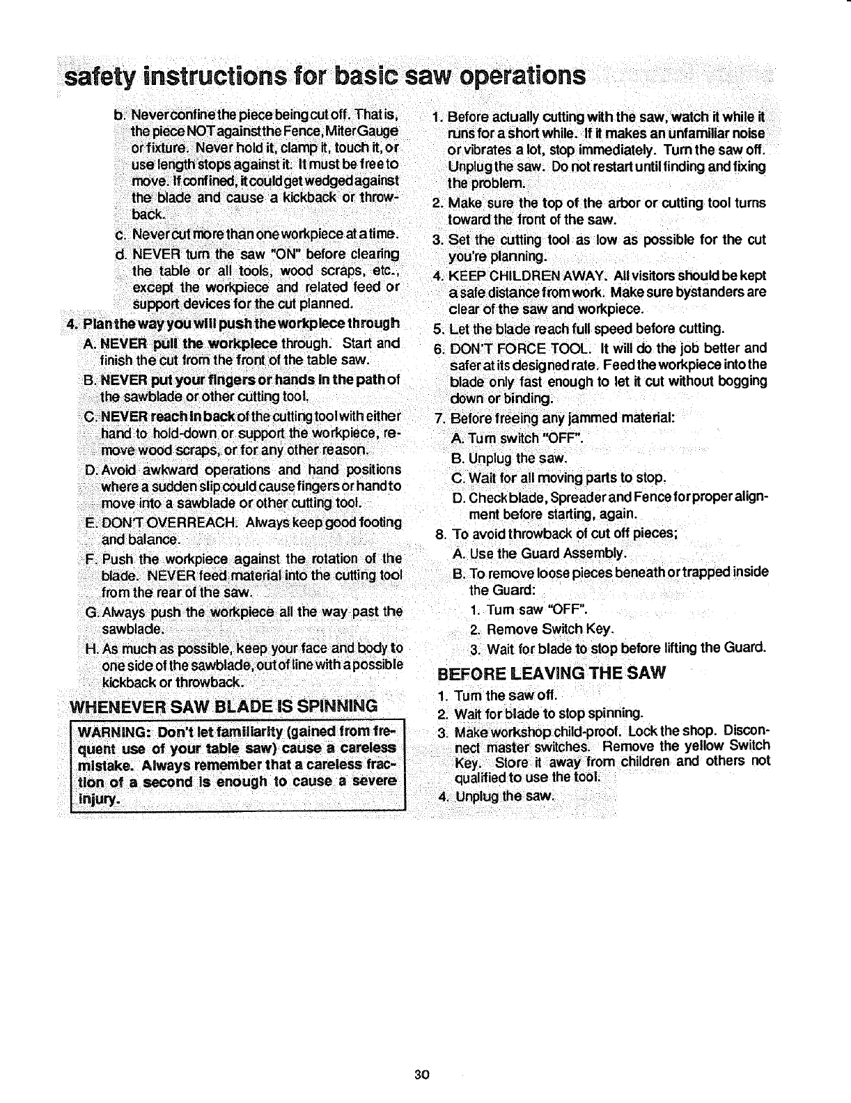
4. Install blade insert by placing key hole slot in insert
over screw head in saw table and pushing insert to
rear of saw table, engaging tab of insert onto saw
table ledge.
Tighten screw.
I WARNING: injury from a thrown
work_.'
To avoid
piece, blade parts, or blade contact, NEVER oper-
ate saw wmthout the proper insert in place. Use
the saw blade insert when sawing. Use the DADO
iNSERT when using aDado blade.
TAB
PHILLIPS
HEAD SCREW
COLLAR
HEX NUT
27
basic saw operations
WORK HELPERS
Before cutting any _on your saw, study all of the
"Basic Saw Operations."
Notice that in order to make some of the cuts;, it is
necessary to use certain devices, "Work Helpers", like
the Push Stick, the Push Block and the Auxiliary Fence/
Work Su_, which you can make yourself.
After you have made a few practice cuts, make upthese
"he_ers before starting arly projects. Make th_ "Push
Stid_"first.
PUSH STICK AND PUSH BLOCK
Make the Push Stick using a piece of I x 2.
THESE EDGES
BE PARALLEL 3/4 PLYWOOD
3/8
NOTE: All dimensions in inches
PUSH BLOCK
3/8 PLYWOOD
SLIGHTLY LESS THAN
THICKNESS OF WORKPIECE
UP TO3/8" \
1-5/8
45 °NOTCH
AUXILIARY FENCE/WORK SUPPORT
Make one usingapiece of3/8 inch and3/4 inch plywood.
Fasten together with glue and woodscrews.
NOTE: Since the Push Block is used with the Auxiliary
Fence, the 4-3/4 inchesdimensions must be held iden-
tical on both the pieces.
3/4 PLYWOOD
/
NOTE: All dimensions in inches
PUSH STICK
Makethe Push Block using a piece of 318in. and 3/4 in.
plywood.
1-1/4
THIS FACE AND THIS
EDGE MUST BE PARALLEL
3/S PLYWOOD
is to prevent dulling the sawblade in the event you
mistakenly cut into the Push Block. NOT_:Al!dimensionInInches
POSitionthe handle in the center of the plywood and AUXIUARY FENCE/WORK SUPPORT
fasten together with glue and woodscrew.
i
" " " rat"
safety mstructmns for basic saw ope ons
BEFORE EACH USE:
before raising or removing the Guard, changing
the cutting tool, changing the setup or adjusting
anything.
B. Check for alignment of moving pads, binding of
moving pads, breakage of parts, saw stability, and
any other conditions that may affect the way the
saw works. If any pad is missing, bent, or broken
in any way, or any electrical part does not work
properly, turn off and unplug the saw.
C. Replace damaged, missing, orfailed parts before
using the saw again.
Make sure the Pawlswork properly. Makesurethe
Spreader is in line with the sawblade.
E. REMOVE ADJUSTING KEYS AND WRENCHES.
Form habit of checkingfor and removing keys and
adjusting wrenches from tool before turning it on.
F. To avoid injury from jams, slips or thrown pieces
(kickback and throwback):
1. USEONLY RECOMMENDEDACCESSORIES
(See page 40). Follow the instructions that
come with the accessories. Using other acces-
sories may be dangerous.
28

safety instructions for basic
2. Choose the right blade or cutting accessory for
the material and the type of cuttingyou plan to
do.
3. Never use grinding wheels, abrasive cut-off
wheels, fdction wheels (metal slitting blades)
wlrewheelsorbuffingwheel. Theycan fly apart
explosively.
4. Choose and inspect your cutting tool carefully.
a. To avoid cuttingtool failure andthrownshrap-
nel (broken pieces of blade), use only 10" or
smaller blades orother cuttingtools marked
for speeds of 5000 rpm or higher.
b. Always use unbroken, balanced blades de-
signed to fit this saw's 5t8 inch arbor.
c. When thru.sawing (making cuts where the
blade comes through the workpiece top),
always use a10 inch diameter blade. This
keeps the Spreader closest to the blade.
d. Do not overtighten arbor nut. Use arbor
wrenches to "snug" it securely.
e. Use only sharp blades withproperlysetteeth.
Consult aprofessional blade sharpenerwhen
in doubt.
f. Keep blades clean of gum and resin.
5. Adjust table inserts flush with the table top.
NEVER use the saw without the proper insert.
6. Make sure allclamps and locks are tight and no
parts have any excessive play.
2, Keep work area clean
A. Cluttered areas and benches invite accidents.
Floor must not be slippery from wax or sawdust.
B. To avoid burnsorother fire damage, never usethe
saw near flammable liquids, vapors or gases.
C. To avoid injury,don'tdo layout,assembly, or setup
work on the table while the blade is spinning. It
could cut or throw anything hitting the blade.
AVOID ACCIDENTAL STARTING - Make sure
switch is "OFF" before plugging saw in.
Plan ahead to protect your eyes, hands, face, ears.
3. Plan your work
A. USE THE RIGHT TOOL - Don't force tool or
attachment to do a job it was not designed for.
B. Dress for safety:
1. Do not wear loose clothing, gloves, neckties or
jewelry (rings, wristwatches). They can get
caught and draw you into moving parts.
2. Wear nonslip footwear.
3. Tie back long hair.
4. Roll long sleeves above the elbow.
5. Noise levels vary widely. To avoid possible
hearing damage, wear ear plugsor muffs when
using saw for long periods of time.
saw operations
6. Any power saw can throw foreign objects into
the eyes. This can cause permanent eye darn-
age. Wear safety goggles (not glasses) that
comply with ANSI Z87.1 (shown on package).
Everyday eyeglasses have only impact resis-
tant lenses. They are not safety glasses. Safety
goggles are available at Sears retail catalog
stores. Glasses or goggles not in compliance
with ANSI Z87.1 could seriously hurt you when
they break.
29
7. For dusty operations, wear adust mask along
with the safety goggles.
C. Inspect your workpiece. Make sure there are no
nailsor foreign objects in the part of the workpiece
to be cut.
D. Plan your cut to avoid KICKBACKS and
THROWBACKS - when a part or all of the work-
piece binds on the blade and is thrown violently
back toward the front of the saw.
1. Inspect your workpiece. Make sure there are no
nails or foreign objects in the part of the work-
piece to be cut.
2. Never cut FREEHAND: Always use either a
Rip Fence, Miter Gauge or fixture to position
and guide the work, so it won't twist, bind on the
blade and kickback.
3. Make sure there's no debris between the work-
piece and its supports.
4. When cutting irregularlyshapedworkpieces,
plan your work so it will not slip and pinch the
blade:
a. Apiece of molding, for example, must lie flat
or be held by a fixture or jig that wili not let it
twist, rock or slip while being cut. Use jigsor
fixtures where needed to prevent workpiece
shifting.
b. Use a different, better suited type of tool for
work that can't be made stable.
5. Use extra caution with large, very small or
awkward workpieces:
a. Use extra supports (tables, saw horses,
blocks, etc.) for anyworkpieces large enough
to tip when not held down to the table top.
NEVER use another person as asubstitute
for a Table Extension, or as additional sup-
port for a work.piece that is longer or wider
than the basic saw table, or to he_p feed,
support or pull the workpiece.
safety instructions for basic saw operations
b. Neverconfinethe piece beingcut off. That is, 1. Before actually cutting with the saw, watch it while it
the piece NOTagainstthe Fence, MiterGauge runs for a short while. If it makes an unfamiliar noise
orfixture. Never hold it, clamp it, touch it, or or vibrates a lot, stop immediately. Turn the saw off,
use length_ops against it. it must be free to Unplug the saw. Do notrestart untilfinding andfixing
move. If confined,it couldget wedged against the problem.
the blade and cause a kickback or throw- 2. Make sure the top of the arbor or cutting tool turns
B. NEVER put your fingers or hands in the path of
D. Avoid awkward operations and hand positions
safer at itsdesigned rate. Feed the workpiece intothe
blade only fast enough to let it cut without bogging
down or binding.
7. Before freeing any jammed material:
A. Tum switch '_)FF".
B. Unplug the saw.
C. Wait for all moving parts to stop.
and balance.
F. Push the workpiece against the rotation of the AUse the Guard Assembly.
blade. NEVERIeed material into the cutting tool B.To removeloosepiecesbeneathortrappedinside
from the rear of the saw the Guard:
G.Always push the workpiece all the way past the 1. Turn saw "OFF".
sawblade.
H. As much as possible, keep yourface and body to
one side of tl_esawblade, outof line with apossible
kickback or throwback.
WHENEVER SAW BLADE iS SPINNING
WARNING: Don't let familiarity (gained from fro- I
quent use of your table saw) cause acareless L
mistake. Always remember that acareless frac-
tion of asecond is enough to cause asevere
injury.
2. Remove Switch Key.
3. Wait for blade to stop before lifting the Guard.
BEFORE L EAVING THE SAW
1. Turn the saw off.
2. Wait for blade to stop spinning.
3. Make workshop child-proof. Lockthe shop. DisCon-
nect master switcheS. Remove the yellow Switch
Key. Store it away from children and others not
qualifiedto use the tool.
4. Unplug the saw.
3O
basic saw operation -using the miter gauge
The MITER GAUGE IS USED when CROSSCUTTING,
MITER CUTTING, BEVEL CUTTING, COMPOUND MI-
TER CUTTING, DADOING and when RABBETING
AND MOLDING across the end of a narrow workpiece.
i...,,o,°,,o°r°.°-,.,,...,.°,....I
the following safety precautions in addition to the
safety instructions on pages 2, 3, 4, 5 28, 29 & 30.
ADDiTiONAL SAFETY iNSTRUCTiONS FOR
CROSS CUT TYPE CUTS=
Before start Ing:
1. Never use the Rip Fence when crosscutting,
2. An auxiliary wood facing attached tothe Miter Gauge
can help prevent workpiece twisting andthrowbacks.
Attach it to the holes provided. Make the facing long
enough and big enough to support yourwork. Make
sure, however, it will not interfere with the sawblade
guard.
3. Use jigs orfixtures to help hold any piece too small to
extend across the furl length of the Miter Gauge face
during the cut. This lets you properly hold the Miter
Gauge and workpiece and helps keep your hands
away from the blade.
While cutting:
1. To avoid blade contact, always hold the Miter Gauge
as shown in this section,
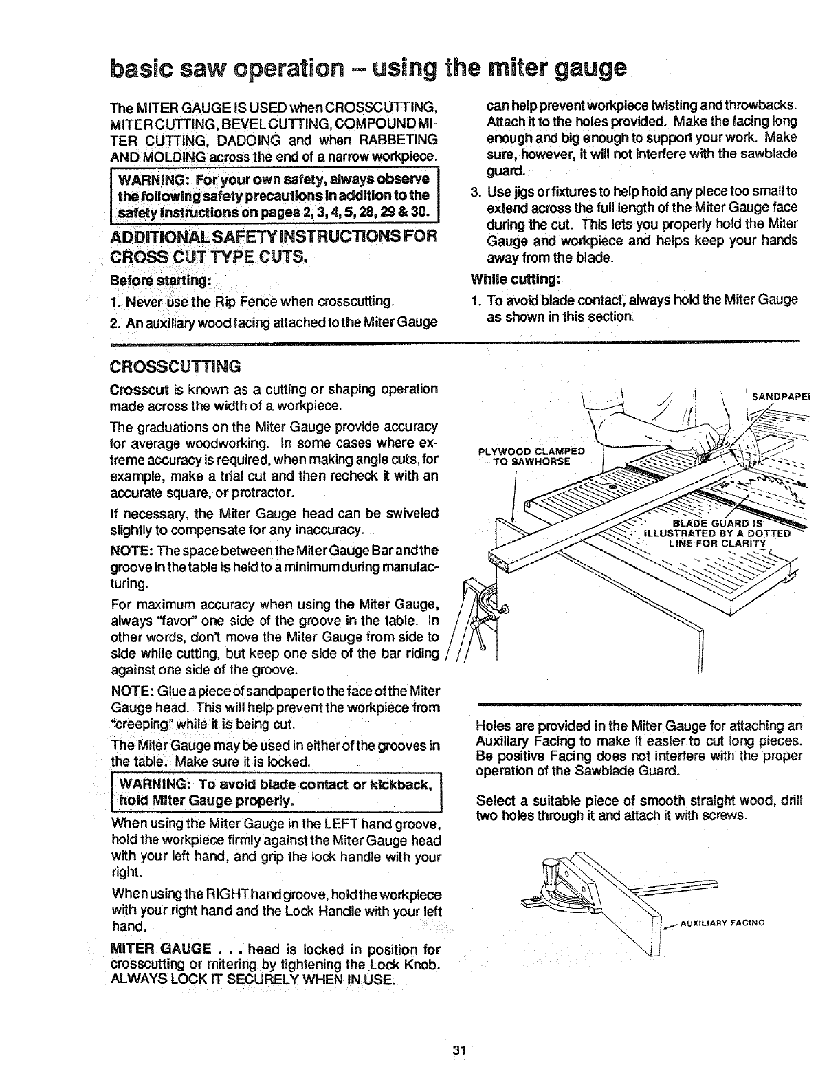
CROSSCUTTING
Crosscut is known as a cutting or shaping operation
made across the width of aworkpiece.
The graduations on the Miter Gauge provide accuracy
for average woodworking, in some cases where ex-
treme accuracy is required, when making angle cuts, for
example, make a trial cut and then recheck it with an
accurate square, or protractor.
If necessary, the Miter Gauge head can be swiveled
slightlyto compensate for any inaccuracy.
NOTE: The space between the Miter Gauge Bar andthe
groove inthe table is held to a minimum dudng manufac-
turing.
For maximum accuracy when using the Miter Gauge,
always "favor" one side of the groove in the table, in
other words, don't move the Miter Gauge from side to
side white cutting, but keep one side of the bar riding
against one side of the groove.
NOTE: Glue a piece of sandpaperto the face of the Miter
Gauge head. This will help prevent the workpiece from
"creeping" while it is being cut.
The Miter Gauge may be used in either of the grooves in
the table. Make sure it is locked.
IWARNING: To avoicl blade contact or kickback, J
hold Miter Gauge properly.
When using the Miter Gauge in the LEFT hand groove,
holdthe workpiece firmly against the Miter Gauge head
with your left hand, and grip the tock handle with your
right.
When using the RIGHThand groove, hold the workpiece
with your right hand and the Lock Handle with your left
hand.
MITER GAUGE... head is locked in position for
crosscutting or mitering by tightening the Lock Knob.
ALWAYS LOCK IT SECURELY WHEN IN USE.
PLYWOOD CLAMPED
TO SAWHORSE
SANDPAPEi
:- LINE FOR CLARITY
Holes are provided inthe Miter Gauge for attaching an
Auxiliary Facing to make it easier to cut long pieces.
Be positive Facing does not interfere with the proper
operation of the Sawbiade Guard.
Select a suitable piece of smooth straight wood, drill
two holes through it and attach it with screws.
31
basic saw operations
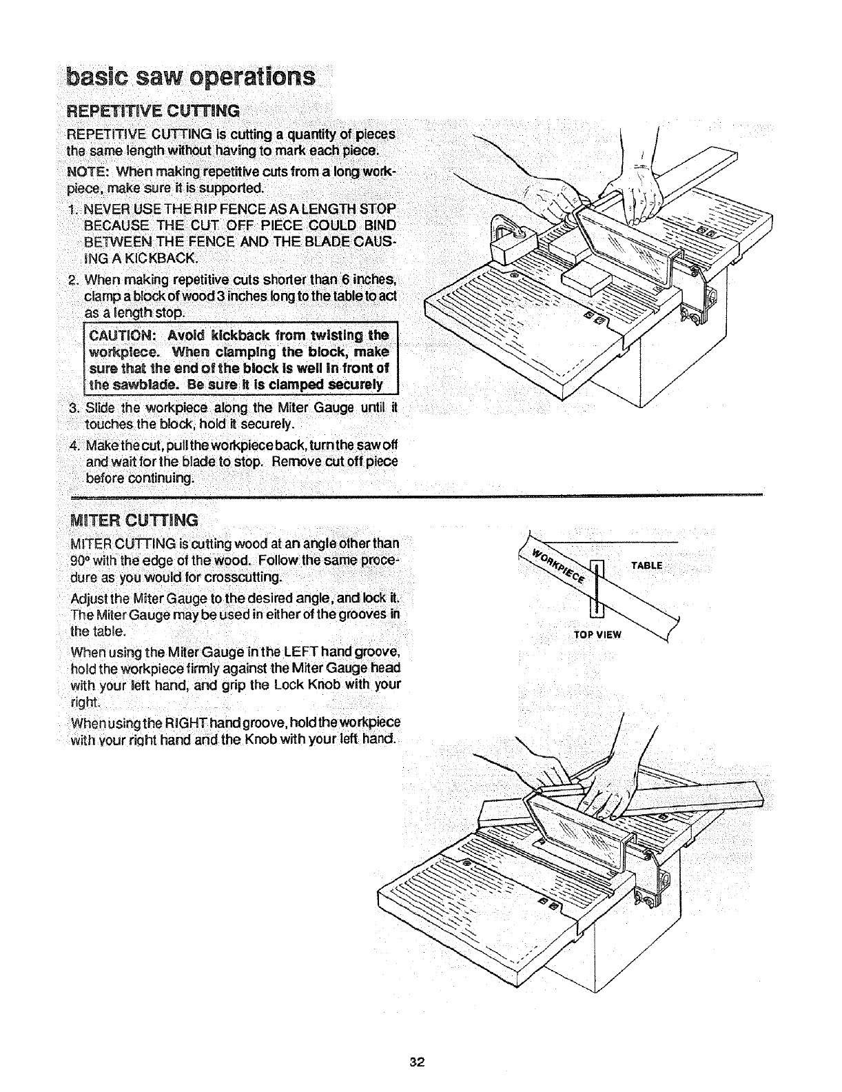
REPETITIVE CUTTING
1. NEVER USE THE RiP FENCE AS A LENGTH STOP
BECAUSE THE CUT OFF PIECE COULD BIND
BETWEEN THE FENCE AND THE BLADE CAUS-
iNG A KICKBACK,
2_ When making repetitive cuts shoder than 6 inches,
camp a block of wood 3 inches longto the table to act
as a length stop.
FCAUTION: Avoid kickback from twisting the
lworkpiece. When c|amplng the block, make I
isure that the end of the bk)ck is well in front of I
L_he sawbiade. Be sure it is clamped securely I
3. Slide the workpiece aong the Miter Gauge until it
touches the block, hold it securely.
4. Makethecut, pullthe workpiece back, turnthe sawofl
and wait for the blade to stop. Remove cut off piece
before continuing.
i .........
MITER CUTTING
MITER CUTTING iscuttingwood at an angle other than
90° with the edge of the wood. Follow the same proce-
dure as you would for crosscutting.
Adjust the Miter Gauge to the desired angle, and lock it.
The Miter Gauge may be used in either of the grooves in
the table.
When using the Miter Gauge in the LEFT hand groove,
hold the Workpiece firmly against the Miter Gauge head
with your left hand, and grip the Lock Knob with your
right.
When usingthe RIGHT hand groove, hold theworkpiece
with ,/our dCjht hand and the Knob with your left hand.
TOP VIEW
TABLE
/
32
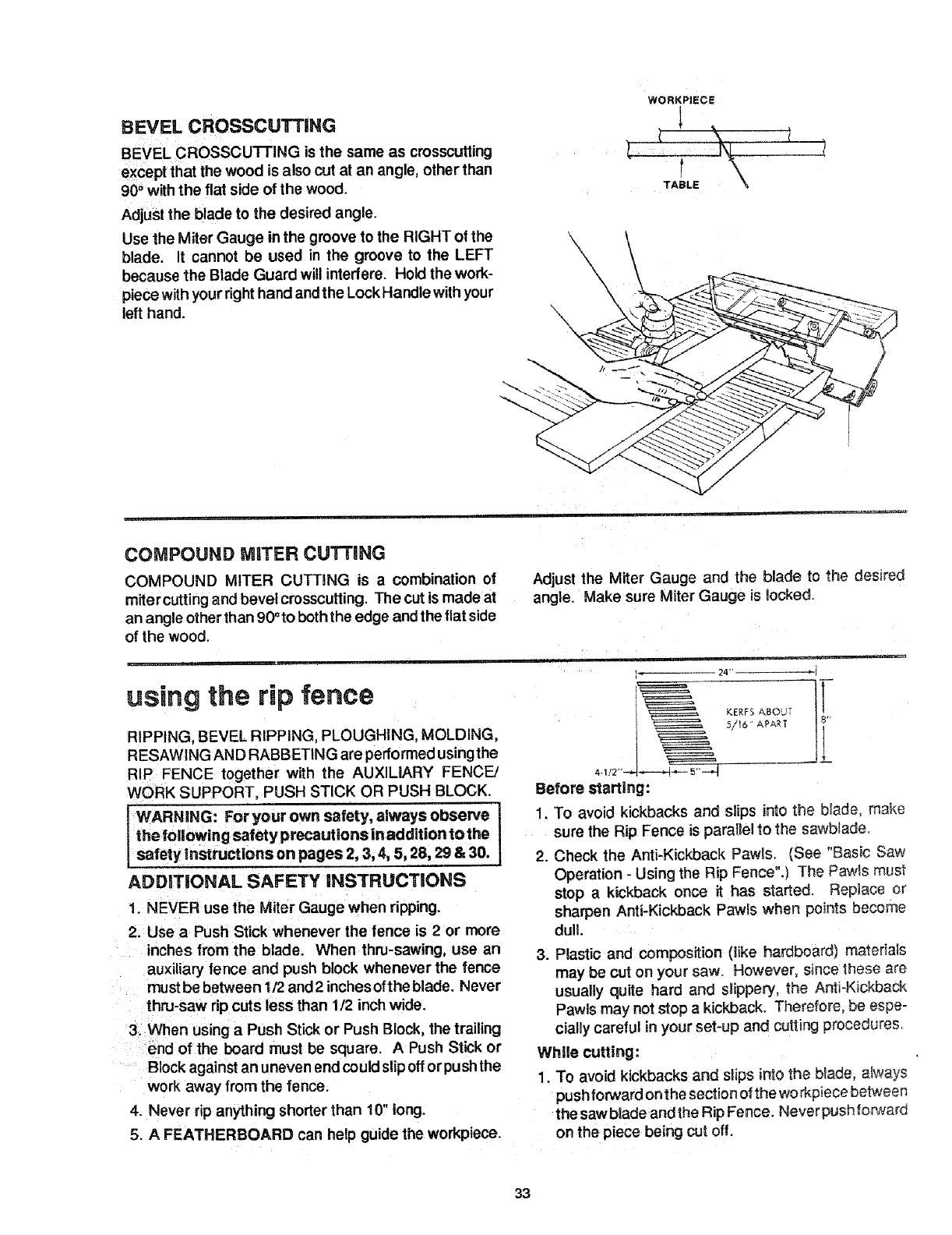
BEVEL CROSSCUTTING
BEVEL CROSSCUTTING is the same as crosscutting
except that the wood is also cut at an angle, other than
90° with the flat side of the wood.
Adjust the blade to the desired angle.
Use the Miter Gauge in the groove to the RIGHT of the
blade. It cannot be used in the groove to the LEFT
because the Blade Guard will interfere. Hold the work-
piece with your right hand and the Lock Handle with your
left hand.
WORKPIECE
_ '
TABLE
COMPOUND MITER CUTTING
COMPOUND MITER CUTTING is a combination of
miter cuttingand bevel crosscutting, The cut ismade at
an angle other than 900to boththe edge and the flat side
of the wood.
Adjust the Miter Gauge and the blade to the desired
angle, Make sure Miter Gauge is locked.
using the rip fence
RIPPING, BEVEL RIPPING, PLOUGHING. MOLDING,
RESAWING AND RABBETING are performed usingthe
RIP FENCE together with the AUXILIARY FENCE/
WORK SUPPORT, PUSH STICK OR PUSH BLOCK,
WARNING: For your own safety, always observe I
the following safety precautions in addition to the I
safety instrucUons on pages 2, 3, 4, 5, 28, 29 & 30.
ADDITIONAL SAFETY iNSTRUCTiONS
1. NEVER use the Miter Gauge when ripping.
2. Use aPush Stick whenever the fence is 2 or more
inches from the blade. When thru-sawing, use an
auxiliary fence and push block whenever the fence
must be between 1/2 and 2 inches ofthe blade. Never
thru-saw rip cuts less than 1/2 inch wide.
3. When using a Push Stick or Push Block, the trailing
end of the board must be square. A Push Stick or
Block against an uneven end could slipoff orpush the
work away from the fence.
4. Never rip anything shorter than 10" long.
5. AFEATHERBOARD can help guide the workpiece.
24
KERFS ABOUT i_
5/16 APART
Before starting:
1. To avoid kickbacks and slips into the blade, make
sure the Rip Fence is paratlel to the sawbtade,
2. Check the Anti-Kickback Pawls. (See "Basic Saw
Operation - Using the Rip Fence".) The Pawls must
stop a kickback once it has started. Replace or
sharpen Anti-Kickback Pawls when points become
dull.
3. Plastic and composition (like hardboard) materiaas
may be cut on your saw. However. since these are
usually quite hard and slippery, the Anti-Kickback
Pawls may not stop a kickback. Therefore, be espe-
cially careful in your set-up and cutting procedures.
While cutting:
1. To avoid kickbacks and slips into the btade, ah_ays
push forward onthe section of the workpiece between
the sawblade andthe Rip Fence. Neverpushforwar_
on the piece being cut off.
33
basic saw operations
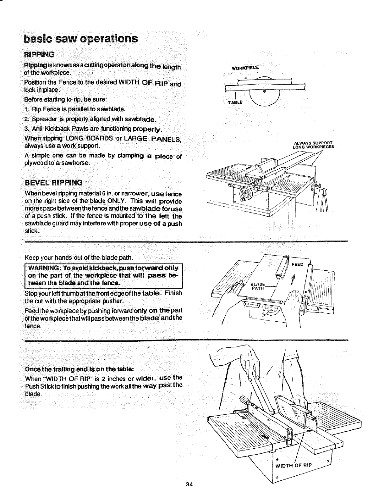
RIPPING
Rmpplngsknown as acutting operation along the length
of the workpiece.
Position the Fence to the desired WIDTH OF RiP and
lock inplace,
Before starting to rip, be sure:
1. Rip Fence is parallel to sawblade.
2. Spreader is properly aligned with sawblade.
3. Anti-Kickback Pawls are functioning properb/.
wORKP!ECE
A simple one can be made by clamping a piece of
plywood to asawhorse.
BEVEL RIPPING
When bevel ripping material 6 in. or narrower, use fence
or=the right side of the blade ONLY. This will provide
morespace between the fence and the sawblade for use
of a push stick. If the fence is mounted to the left, the
sawblade guard may interfere with proper use of a push
stick.
ALWAYS SUPPORT
LONG WORKPIECES
Keep your hands out of the blade path.
WARNING: To avoid kickback, push forward only l
on the part of the workplece that wll! pass be-
tween the blade and the fence.
the cut with the appropriate pusher.
Feed the wo rkpiece by pushing forward only on the part
ofthe workpiecethat will pass between the blade andthe
fence.
/
t
I
\
Once the trailing end is on the table:
wl 1_ * - °r
When WIDTH OF RiP s 2 inches or wide, use the
Push Stickto finish pushingthe work all the way past the
blade.
34
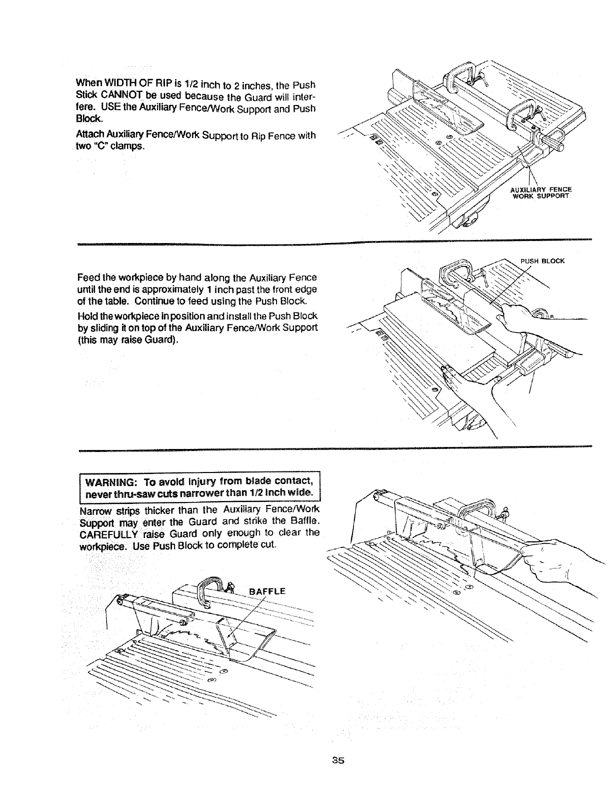
When WIDTH OF RiP is 1/2 inch to 2inches, the Push
Stick CANNOT be used because the Guard will inter-
fere. USE the Auxiliary Fence/Work Support and Push
B ck.
Attach Auxiliary Fence/Work Support to Rip Fence with
two i'C" clamps.
AUXILIARY FENCE
WORK SUPPORT
Feed the workpiece by hand along the Auxiliary Fence
until the end is approximately 1 inch past the front edge
of the table. Continue to feed using the Push Block.
Hold theworkplece inposition and installthe Push Block
by sliding it on top of the Auxiliary Fence/Work Support
(this may raise Guard).
\\\
\\ \
IWARNING: To avoid Injury from blade contact,
|
,,never thru-saw cuts narrower than 1/2 inch wide. I
Narrow strips thicker than the Auxiliary Fence/Work
Support may enter the Guard and strike the E3aflle.
CAREFULLY raise Guard only enough to clear the
workpiece. Use Push Block to complete cut.
BAFFLE
\\
35
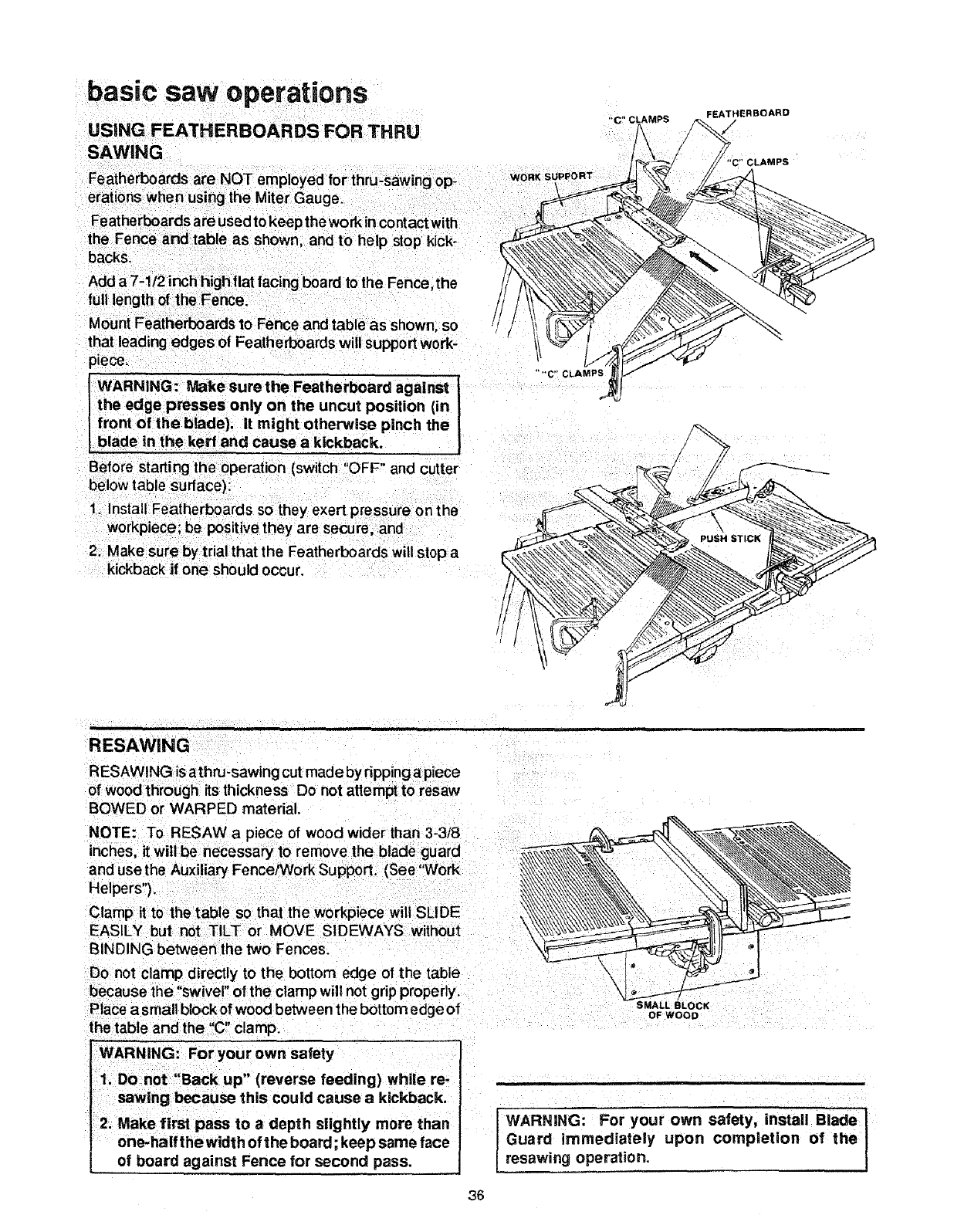
USING FEATHERBOARDS FOR THRU
SAWING
FEATHERBOARD
"C" CLAMPS
backs.
piece.
iWARNING: Make sure the Featherbeard againsl
Ithe edge presses only on the uncut position (in
front of tl_e blade}, it might otherwise pinch the
blade in the kerr and cause akickback.
Before starting the operation (switch "OFF" and cutter
below table surface):
1. Install Featherboards so they exert pressure on the
workpiece be positive they are secure, and
RESAWING
RESAWING isathru-sawing cut made by ripping a piece
of wood through its thickness Do not attempt to resaw
BOWED or WARPED material.
NOTE: To RESAW a piece of wood wider than 3-3/8
inches, it will be necessary to remove the blade guard
and use the Auxiliary Fence/Work Support. (See ';'Work
Helpers").
BINDING between the two Fences.
Do not clamp directly to the bottom edge of the table
because the "swivel" of the clamp will not grip properly.
Place a small blocker wood between the bottom edge of
the table and the"C" clamp. OF WOOD
WARNING: For your own safety
1. Do not "Back up" (reverse feeding) while re-
sawing because this could cause akickback.
2. Make first pass to a depth slightly more than
one-half the width of the board; keep same face
of board against Fence for second pass. WARNING: For your own safety, install Blade
Guard immediately upon completion of the
resawing operation.
36
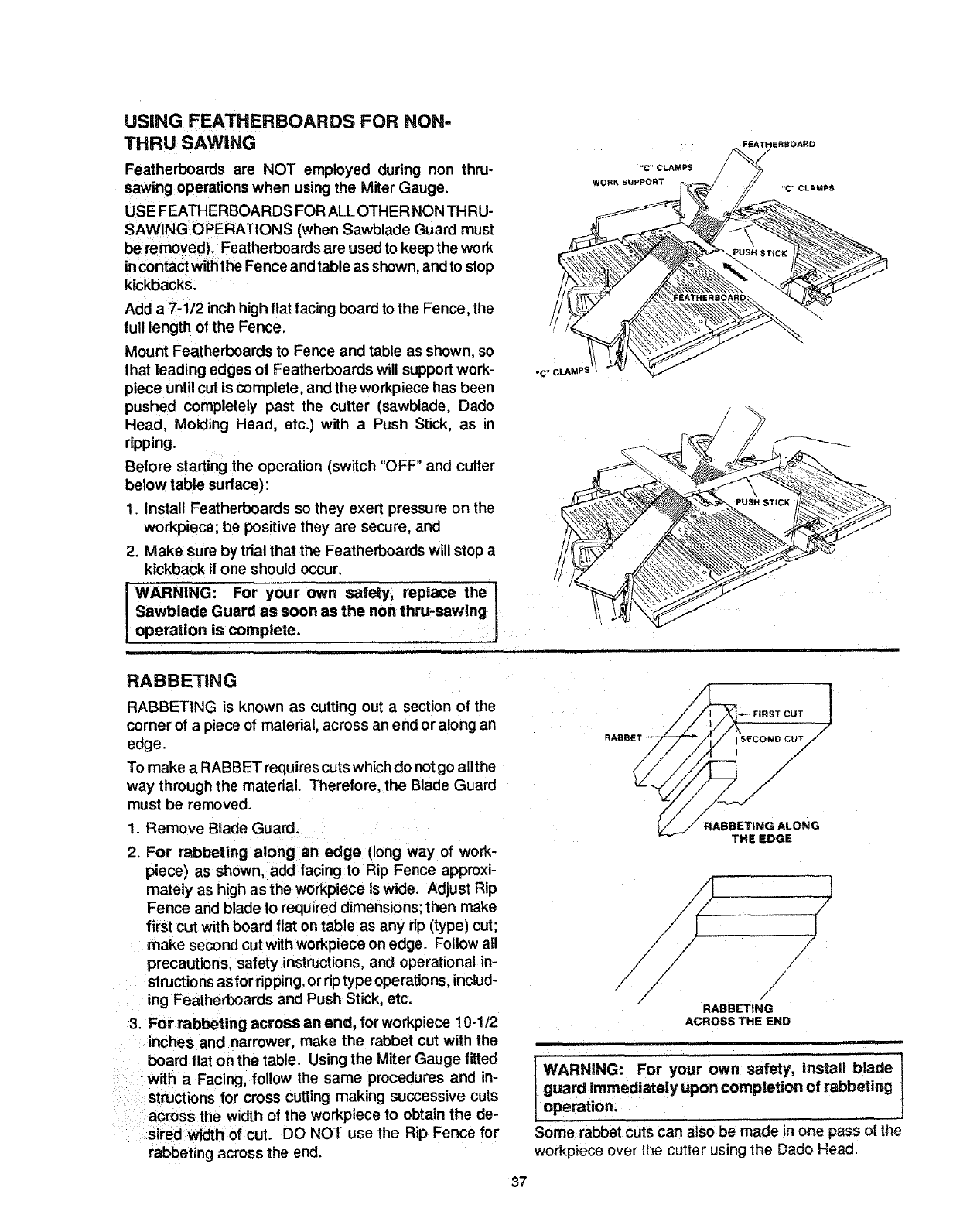
USING FEATHERBOARDS FOR NON-
THRU SAWING
Featherboards are NOT employed during non thru-
sawing operations when using the Miter Gauge.
USE FEATHERBOARDS FOR ALLOTHER NON THRU-
SAWING OPERATIONS (when Sawblade Guard must
be removed). Featherboards are used to keep the work
incontact withthe Fence and table as shown, and to stop
kickbacks.
Add a 7-1/2 inch high fiat facing board to the Fence, the
full length of the Fence.
Mount Featherboards to Fence and table as shown, so
that leading edges of Featherboards will supportwork-
piece untilcut is complete, and the workpiece has been
pushed completely past the cutter (sawblade, Dado
Head, Molding Head, etc.) with a Push Stick, as _n
ripping.
Before starting the operation (switch "OFF" and cutter
below table sudace):
1. Install Featherboards so they exert pressure on the
workpiece; be positive they are secure, and
2. Make sure by trial that the Featherboards will stop a
kickback if one should occur.
WARNING: For your own safety, replace the I
Sawblade Guard as soon as the non thru-sawing I
operation is complete.
FEATHERBOARD
"C"CLAMPS
RABBETING
RABBETING is known as cutting out a section of the
corner of a piece of materiat, across an end or along an
edge.
To make aRABBET requirescuts whichdo notgo all the
way through the material. Therefore, the Blade Guard
must be removed.
1. Remove Blade Guard.
2. For rabbeting along an edge (long way of work-
piece) as shown, add facing to Rip Fence approxi-
mately as high as the workpiece iswide. Adjust Rip
Fence and blade to required dimensions; then make
first cut with board flat on table as any rip (type} cut;
make second cut with workpiece on edge. Follow all
precautions, safety instructions, and operational in-
structions as for ripping, or dp type operations, includ-
ing Featherboards and Push Stick, etc.
3. For rabbeting across an end, for workpiece 10-1/2
inches and narrower, make the rabbet cut with the
board flat on the table. Using the Miter Gauge fitted
with a Facing, follow the same procedures and in-
structions for cross cutting making successive cuts
across the width of the workpiece to obtain the de-
sired width of cut. DO NOT use the Rip Fence for
rabbeting across the end.
|
FIRST CUT 7
sEco.ocUT//
/
/
/
/
RABBETING ALONG
THE EDGE
/
l
/
/
/
/
/
RABBETING
ACROSS THE END
WARNING: For your own safety, install blade I
guard immediately upon completion of rabbeting
operation.
Some rabbet cuts can also be made in one pass of the
workpiece over the cutter using the Dado Head.
37
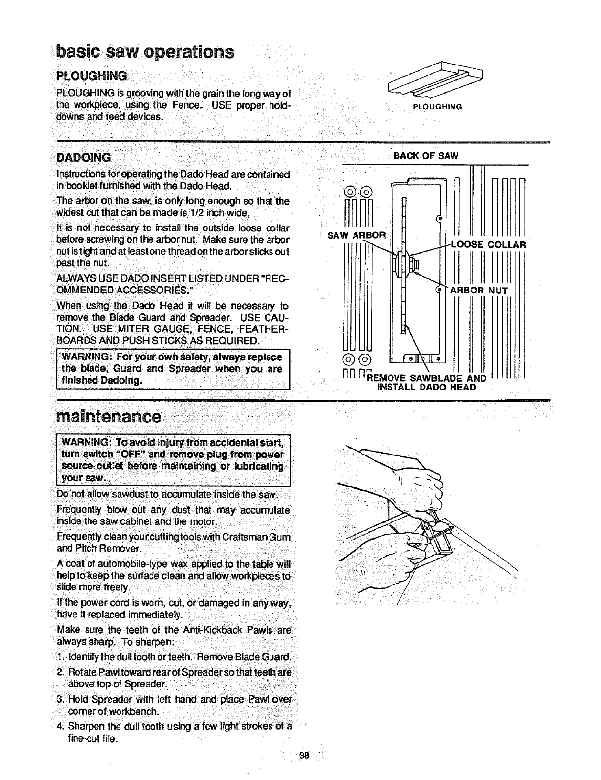
basic saw operations
PLOUGHING
PLOUGHING is grooving with the grain the longway of
the workpiece, using the Fence. USE proper hold-
downs al_clfeed devils. PLOUGHING
BACK OF SAW
It is not necessary to install the outside loose collar
before screwing onthe arbor nut. Make sure the arbor
nutistight and at least one thread onthe arbor st cksout
past the nut.
ALWAYS USE DADO INSERT LISTED UNDER "REC-
OMMENDED ACCESSORIES."
When using the Dado Head it will be necessary to
remove the Blade Guard and Spreader. USE CAU-
TION. USE MITER GAUGE, FENCE, FEATHER-
BOARDS AND PUSH STiCKSAS REQUIRED.
iWARNING: For your own safety, always replace ]
the blade, Guard and Spreader when you are I
finished Dadoing.
SAW ARBOR iiZ!coLLF
NUT
Nn _REMOVE SAWBLADE AND
INSTALL DADO HEAD
!
ma ntenance
] WARNING: Toavoid lnjuryfrom accidentalstart, I
I turn switch OFF" and remove plug from power
Isource outlet before maintaining or lubrl_ing !
I your saw.
Do not allow sawdust to accumulate inside the saw.
Frequently clean your cuttingtoolswith Craftsman Gum
and Pitch Remover.
slide more freely.
itthe power cord is worn, cut, or damaged in anyway,
have it replaced immediately.
Make sure the teeth of the And-Kickback Pawls are
always sharp. To sharpen:
1. Identify the dull tooth orteeth_ Remove Blade Guard.
comer of workbench.
4. Sharpen the dull tooth using a few light strokes of a
fine-cut file.
38
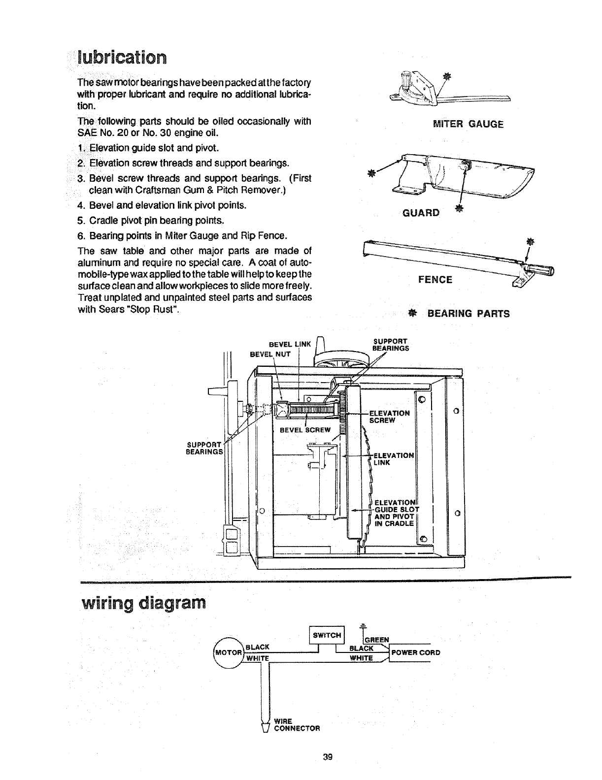
lubrication
The sawmotor bearings have been packed at the factory
with proper lubricant and require no additional lubrica-
tion.
The following parts should be oiled occasionally with
SAE No. 20 or No. 30 engine oil.
1. Elevation guide slot and pivot,
2. Elevation screw threads and support bearings.
3. Bevel screw threads and support bearings. (First
clean with Craftsman Gum & Pitch Remover.)
4. Bevel and elevation link pivot points.
5. Cradle pivot pin bearing points.
6. Bearing points in Miter Gauge and Rip Fence.
The saw table and other major parts are made of
aluminum and require no special care. A coat of auto-
mobile-type wax applied to the table will help to keep the
surface clean and allow workpieces to slide more freely.
Treat unplated and unpainted steel parts and surfaces
with Sears "Stop Rust".
MITER GAUGE
GUARD
BEARING PARTS
SUPPORT
SEARiNGS
wiring diagram
BEVEL LINK SUPPORT
BEARINGS
BEVEL NUT
O
TBLACK
WIRE
CONNECTOR
TGREEN
WHITEBLACK"_POWER CORD
39
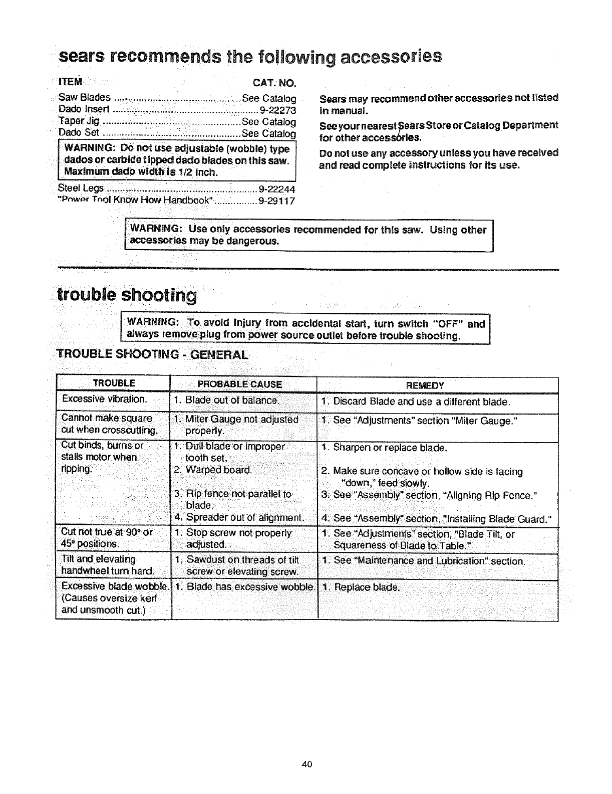
sears recommends the following accessories
ITEM CAT. NO.
Saw Blades .............................................. See Catalog
Dado insert ..................................................... 9-22273
Taper Jig .................................................. See Catalog
Dado Set .................................................. See Catalog
WARNING: Do not use adjustable (wobble) type I
dados or carbide tipped dado blades on this saw. I
Maximum dado width is 1/2 inch.
Steel Legs ....................................................... 9-22244
"Pnw_r TnoI Know How Handbook". ............... 9-29117
Sears may recommend other accessories not listed
in manual
See your nearest _ears Store or Catalog Department
for other accessbrles.
Do not use any accessory unless you have received
and read complete instructions for its use.
WARNING: Use only accessories recommended for this saw. Using other
accessories may be dangerous.
m
troub e shootmg
WARNING: To avoid injury from accidental start, turn switch "OFF" and 1
always remove plug from power source outlet before trouble shooting. I
]'ROUBLE SHOOTaNG - GENERAL
,,TROUBLE REMEDY
!. Discard Blade and use a different blade.
Cannot make square 1. M ter Gauge not adjusted 1See "Adjustments" section "Miter Gauge."
W.I
cut hen crosscutting properly
Cut binds, burns or 1. Dull blade or improper 1. Sharpen or replace blade.
Cut not true at 900 or "1. Stop screw not properly ,1. See "Adjustments" section,' Blade Tilt, or
45° positions, adjusted. I Squareness of Blade to Tab e"
s, , , ......
4O
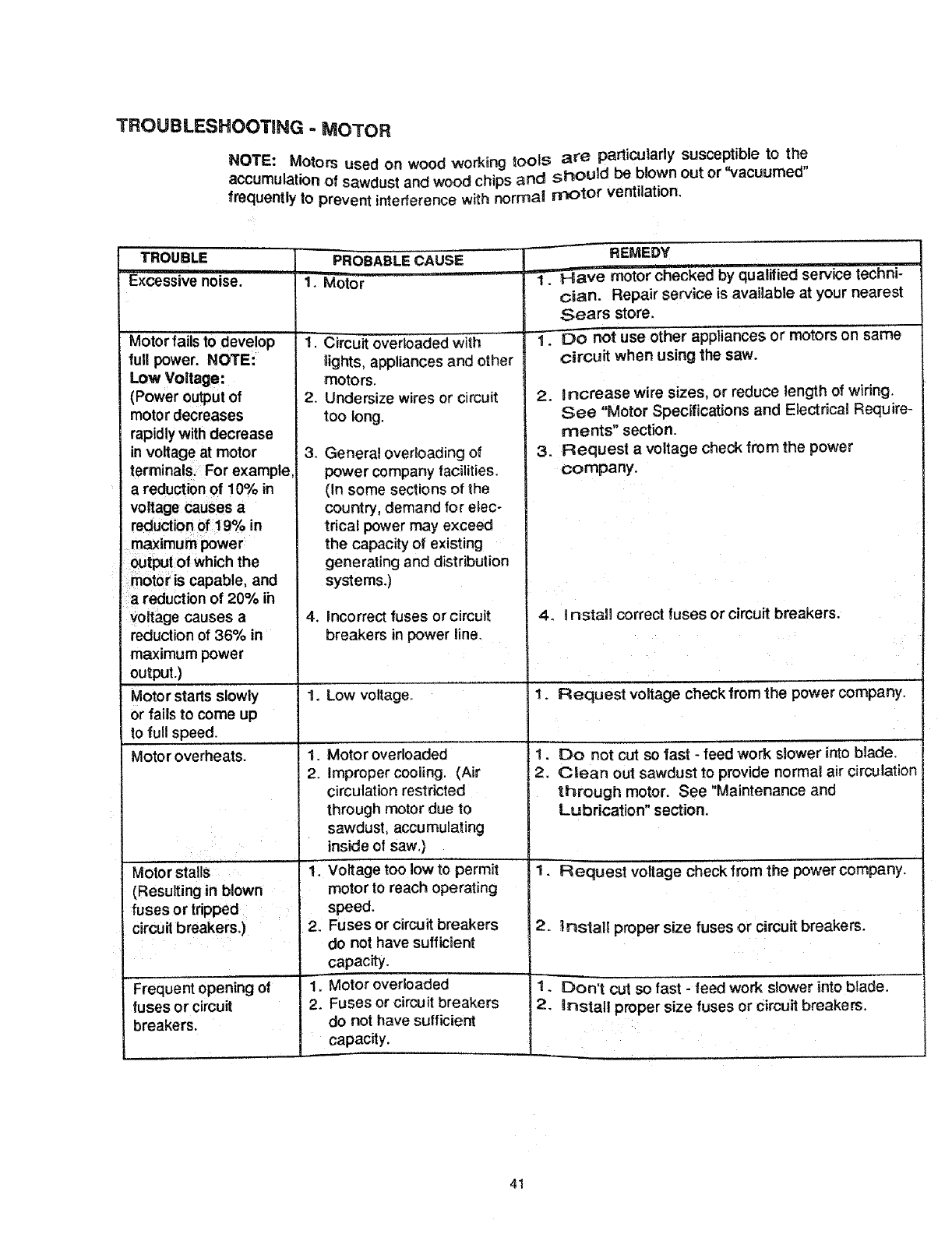
TROUBLESHOOTING - MOTOR
NOTE: Motors used on wood working too_s are particularly susceptible to the
accumulation of sawdust and wood chips and should be blown out or %,acuumed"
frequently to prevent interference with normat rr_otor ventilation.
TROUBLE
Excessive noise.
Motor fails to develop
full power. NOTE:
Low Voltage:
(Power outputof
motor decreases
rapidly with decrease
involtage at motor
terminals. For example,
areduction of 10% in
voltage causes a
reductionof 19% in
maximum power
output of which the
motor is capable, and
a reduction of 20% ih
voltage causes a
reduction of 36% in
maximum power
output.)
Motor starts slowly
or falls to come up
to full speed.
Motor overheats.
Moto r stalls
(Resulting in blown
fuses or tripped
circuit breakers.)
Frequent opening of
fuses or circuit
breakers.
PROBABLE CAUSE
1. Motor
1. Circuit overloaded with
lights, appliances and other
motors.
2. Undersize wires or circuit
too long.
General overloading of
power company facilities.
(In some sections of the
country, demand for elec-
trical power may exceed
the capacity of existing
generating and distribution
systems.)
.
4. incorrect fuses or circuit
breakers in power line.
1. Low voltage.
REMEDY
1.__motor checked by qualified service techni-
cian. Repair service is available at your nearest
Sears store.
1. Do not use other appliances or motors on same
circuit when using the saw.
2. increase wire sizes, or reduce length of wiring.
See "Motor Specifications and Electrical Require-
ments" section.
3. Request a voltage check from the power
company.
4. Install correct fuses or circuit breakers.
!. Request voltage check from the power company.
1. Do not cut so fast - feed work slower into blade.
2. Clean out sawdust to provide normal air circulation
through motor. See "Maintenance and
Lubrication" section.
1. Request voltage check from the power company.
1. Motor overloaded
2. Improper cooling. (Air
circulation restricted
through motor due to
sawdust, accumulating
inside o! saw.)
1+ Voltage too low to permit
motor to reach operating
speed.
2. Fuses or circuit breakers
do not have sufficient
capacity.
1. Motor overloaded
2. Fuses or circuit breakers
do not have sufficient
capacity.
2. _nstall proper size fuses or circuit breakers.
D '
1. on tcut so fast - feed work slower into btade.
2. install proper size fuses or circuit breakers.
41
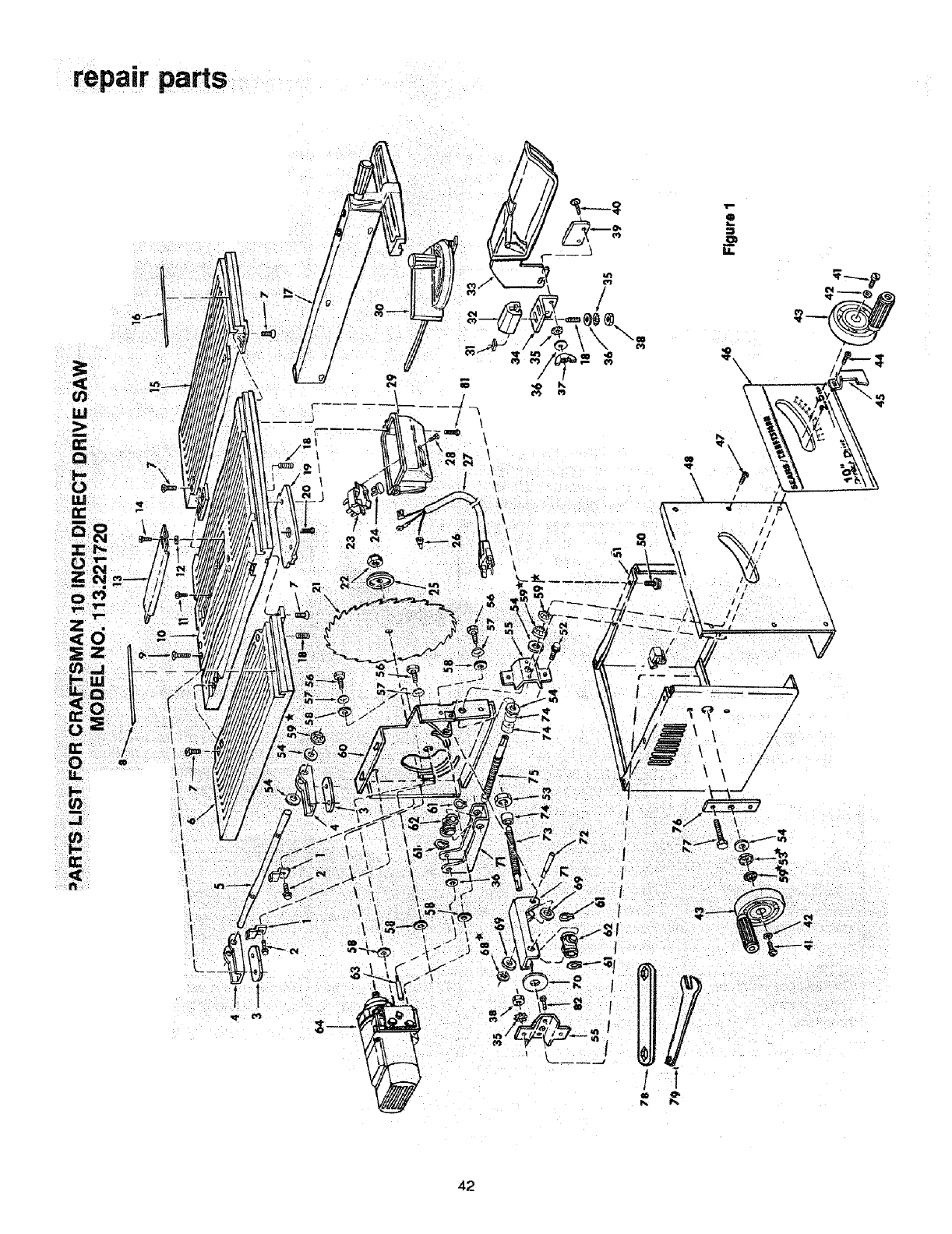
repair parts
I
/
ff
/!
tll
1
I
I
42

oE
"0 r_
.- _
_R
E._N
mz
E
E !_,,
_=
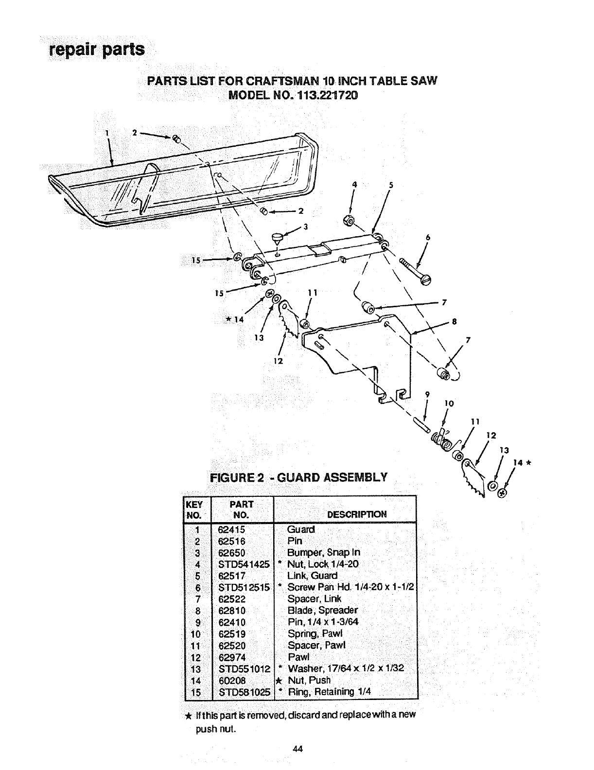
PARTS LIST FOR CRAFTSMAN 10 INCH TABLE SAW
MODEL NO. 1113.221720
4 5
1/
÷..
6
\
13
I
12
FIGURE 2 - GUARD ASSEMBLY
KEY I
NO.i
7
/
i
8 62810
9 62410 Pin, 1/4 x 1-3/64
10 62519 I Spring Pawl
11 62520 Spacer, Paw!
12 62974 .Pawl
13 STD551012 Washer 17/64 x 1t2 x 1/32
14 60208 _ Nut Push
15 .S'TD581025 Ring, Retaining 1/4
Ifthis part is removed, discard and replacewith a new
push nut.
44
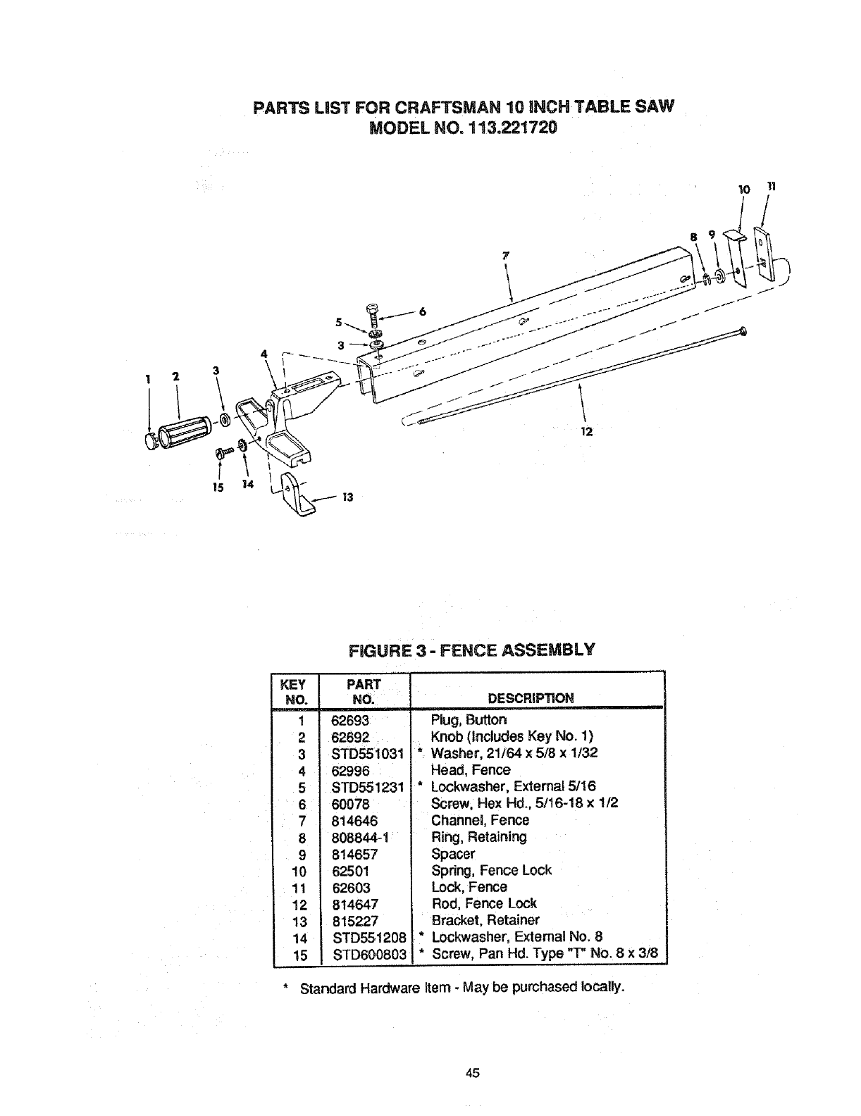
PARTS LIST FOR CRAFTSMAN 10 iNCH TABLE SAW
MODEL NO. 113,221720
10 11
8 9
4
3
t
15 13
FIGURE3 FENCE ASSEMBLY
KEY PART
NO. NO.
162693
2 62692
3 STD551031
462996
5 STD551231
6 60078
7 814646
8 808844-1
9 814657
10 62501
11 62603
12 814647
13 815227
14 STD55!208
15 STD600803
DESCRIPTION
Plug, Button
Knob (Includes Key No. 1)
* Washer, 21/64 x 5/8 x 1/32
Head, Fence
* Lockwasher, External 5/16
Screw, Hex Hd., 5/16-18 × 1t2
Channel, Fence
Ring, Retaining
Spacer
Spring, Fence Lock
Lock, Fence
Rod, Fence Lock
Bracket, Retainer
* Lockwasher, External No. 8
* Screw, Pan Hd. Type "T" No. 8 x 3/8
Standard Hardware Item -May be purchased locally.
45
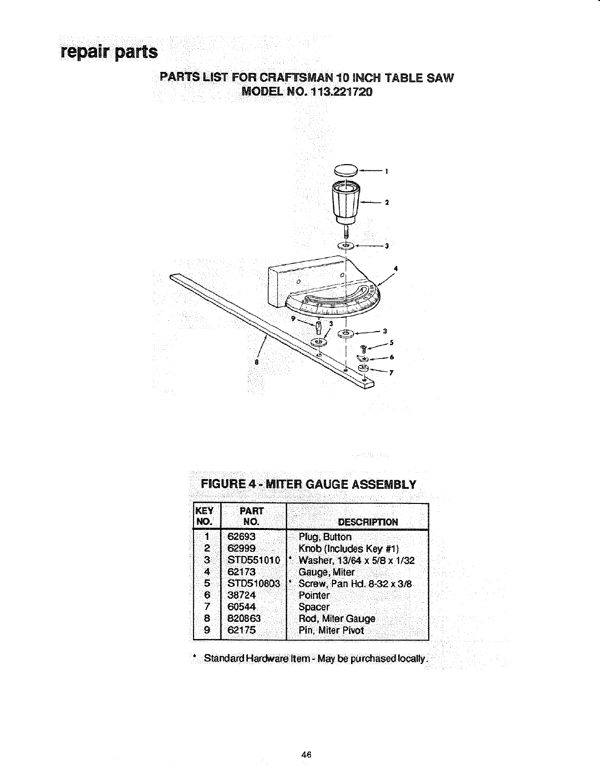
PARTS LiST FOR CRAFTSMAN 10 iNCH TABLE SAW
MODEL NO. 113.221720
_:ii i! _
_ _ • i _
1 S2693 Pleg; B_0n
2 62999 iE_b (i_¢iOdes Key #i)
1/32
3/8
6_724 ii_r
7,605_ S
8 820863 ter Gauge
62175 Pini Mite_ Pivot
46

notes
ii
ii i
i
i ,
i,i
i
i
m
47
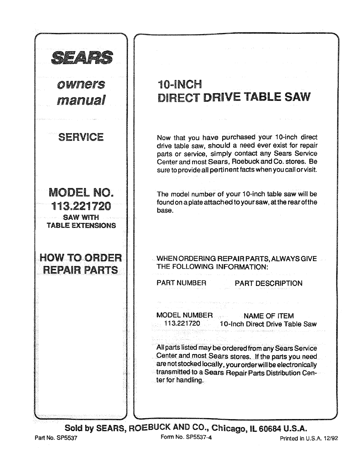
10-INCH
DIRECT DRIVE TABLE SAW
Now that you have purchased your 10-inch direct
drive table saw, should a need ever exist for repair
parts or service, simply contact any Sears Service
Center and most Sears, Roebuck and Co, stores. Be
sure to provide all pertinent facts when you call or visit.
The model number of your 10-inch table saw will be
found on a plate attached to your saw, at the rear ofthe
base.
WHEN ORDERING REPAIR PARTS, ALWAYS GiVE
THE FOLLOWING iNFORMATiON:
PART NUMBER PART DESCRIPTION
MODEL NUMBER NAME OF ITEM
t 13.221720 10-inch Direct Drive Table Saw
All parts listed may be ordered from any Sears Service
Center and most Sears stores, if the parts you need
are not stocked locally, you rorderwili be electronically
transmitted to a Sears Repair Parts Distribution Cen-
ter for handling.
Sold by SEARS, ROEBUCK AND CO., Chicago, IL 60684 U.S.A.
Part No. SP5537 Form No. SP5537-4 Printed in U.S.A. 12/92
