Craftsman 113221740 User Manual 10 BENCH TOP TABLE SAW Manuals And Guides L0707044
CRAFTSMAN Saw Table Manual L0707044 CRAFTSMAN Saw Table Owner's Manual, CRAFTSMAN Saw Table installation guides
User Manual: Craftsman 113221740 113221740 CRAFTSMAN 10 BENCH TOP TABLE SAW - Manuals and Guides View the owners manual for your CRAFTSMAN 10 BENCH TOP TABLE SAW #113221740. Home:Tool Parts:Craftsman Parts:Craftsman 10 BENCH TOP TABLE SAW Manual
Open the PDF directly: View PDF ![]() .
.
Page Count: 42
f
\
Save This Manual
For Future Reference
SEAfR8
ownel"s
manual
MODEL NO.
113=221740
Serial
Number.
Model and serial numbers may
be round at the rear of the
base
You should record botll model
and serial number in a safe
place for future use.
FO YOUR
;AFETY
READ ALL
INSTRUCTIONS
CAREFULLY
Pa_ NoSP5754
8 , Rt6/
10 iNCH BENCH TOP
TABLE SAW
®assembly
,operating
. repair parts
Sears, Roebuck and Co., Hoffman Estates, IL 60179 U.S.A.
J
Printed in USoA,
FULL ONE YEAR WARRANTY ON CRAFTSMAN TABLE SAW
If within one year from the date of purchase, this Craftsman Table Saw fails due to adefect in material
or workmanship, Sears will repair it, free of charge.
WARRANTY SERVICE IS AVAILABLE BY SIMPLY CONTACTING THE NEAREST SEARS SERVICE
CENTER/DEPARTMENT THROUGHOUT THE UNITED SIATESo
This warranty applies only while this product is used in the United States,
This warranty gives you specific legal rights, and you may also have other rights which vary from
state to state.
Sears, Roebuck and Co, D1817 WA Hoffman Estates, IL, 60179
Safety Instructions For Table Saw
Safety Signal Words:
DANGER: means if the safety information is not followed
someone will be seriously injured or killed.
WARNING: means ff the safety information is not followed
someone could be seriously injured or killed.
CAUTION: means if the safety information is not followed
someone may be injured
Before Using The Saw:
WARNING: to avoid mistakes that could cause seri-_
ous, permanent injury, do not plug the table saw in I
until the following steps have been satisfactorily I
completed, J
• Completely assemble and align saw (See pages 8-18)
• Learn the use and function of the ON-OFF switch (See
page 13) blade guard, spreader; anti-kickback device,
miter gauge, rip fence, table insert, blade elevation and
blade tilt controls (See page 20)
• Review and understand ill safety insiructions and
operating procedures in this manual
• Review the maintenance methods for this saw (See
page 33-34)
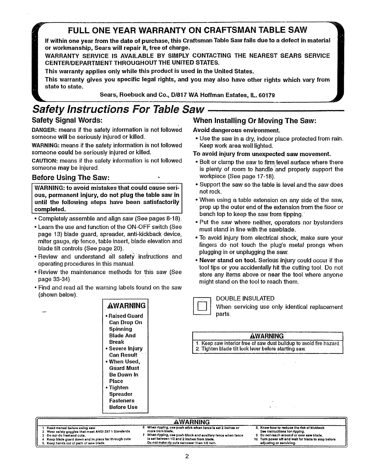
• Find and read all the warning labels found on the saw
(shown beioW)o
kWARNING
• Raised Guard
Can Drop On
Spinning
Blade And
Break
•Severe Injury
Can Result
.When Used,
Guard Must
Be Down In
Place
-Tighten
Spreader
Fasteners
Before Use
When Install!ng Or Moving The Saw:
Avoid dangerous environment,
•Use the saw in a dry, indoor place protected from rain_
Keep work area well lighted,
To avoid injury from unexpected saw movement,
oBelt or clamp the saw to firm level surface where there
is plenty of room to handle and properly support the
workpiece (See page 17-18).
oSupport the saw so the table is level and the saw does
not mck_
oWhen using a table extension on any side of the saw,
prop up the outer end of the extension from the floor or
bench top to keep the saw from tipping/
° Put the saw where neither; operators nor bystanders
must stand in line with the sawblade.
• To avoid injury from electrical shock, make sure your
fingers do not touch the plug's metal prongs when
plugging in or unplugging the saw,
• Never stand on tool. Serious injury could occur if the
tool tips or you accidentally hit the cutting too! Do not
store any items above or near the tool where anyone
might stand on the tool to reach them
[_ DOUBLE INSULATED
When servicing use only identical replacement
parts
_kWARNING 1
1, Keepsawinteriorfree ofsawduetbuildupto avoidfirehazard
2_Tightenbladeti_tlockleverbeforestarting saw,
_WARNING
I F_0td tttmt_tttt _t_lOtl UlIflg ItlW _Wttltl tfpp_, U_ pU=h =ttCk wh_ tQr_ceIn set 2 [ncttel_ o1 8_ K_w h_W Io ,'edt=ce 1he d_k of k_:kbact<
2 W_l_*laf_tygoQgl_slh=blmNIANSlZ_7_ 5fc=mcho_'d_ morattombl_dm. S_lf|ttt, ltuc_olltJ |or_lp_lng,
3 DO _0! do _tochl_rtd cut_. 7Whln rlpp_ng_ use pu|h blt_ck nnd auxiliary f=no_ wh_ f_n¢_ 9Do not reach _toull_ a_ ovlt sew hi,do.
4 Keep btld_ g_lt_d _aw_t i_ I_ pflc_ _o( |hro_gh Ct_ _l ea! belw_er_ 1t2 a/_f 2 [ll_h_ from bhK_. 1_ Tutti powlr o/f I_ Wilt for bl#d_ Io i|op befor_
5. Keep httttd_ 0_1 o_ p_ttt of _w btide. D_ _o_ tc_lke t_p ¢u_l rmrrowlr then f/2 _nch. =dJul_ln_ or Ii_l_lng_
2

Before Each Use:
inspect your saw.
, To avoid injury from accidental starting, turn the switch
off, unplug the saw, and remove the switch key before
raising or removing the guard, changing the cutting
tool, changing the setup, or' adjusting anything..
*Check for alignment of moving parts, binding of moving
parts, breakage of parts, saw stability, and any other
conditions that may affect the way the saw works°
*If any part is missing, bent or broken in any way, or any
electrical part does not work properly, turn the saw off
and unplug the saw_
= Replace damaged or missing parts before using the
saw again.
oUse the sawblade guard, spreader and anti-kickback
pawls for any thru-sawing (whenever the blade comes
through the top of the workpiece). Make sure the anti-
kickback pawls work properly. Make sure the spreader
is in line with sawblade (See page 10-1!)..
° Make sure all clamps and locks are tight and no parts
have any excessive play.
= Remove adjusting keys and wrenches. Form a habit of
checking for' and removing keys and adjusting
wrenches from table top before turning it on.
°Make sure all clamps and locks are tight and no parts
have excessive play.
To avoid injury from jams, slips or thrown pieces
(kickbacks or throwbacks):
Inspect your blade.
, Choose the right blade or' cutting accessory for the
material and the type of cuttingyou plan to doe
oNever use grinding wheels, abrasive cutoff wheels,
friction wheels (metal cutting blades) wire wheels or
buffing wheels° They can fly apart explosively.
° Choose and inspect your' cutting toot carefully:
- To avoid cutting tool failure and thrown shrapnel (bro-
ken pieces of blade), use only t0 inch or smaller
blades or' other cutting tools marked for speeds of
5000 rpm or higher..
- Always use unbroken, balanced blades designed to
fit this saw's 5/8 inch arbor.
-When thru-sawing (making cuts where the blade
comes through the workpiece top), always use a 10
inch diameter blade. This keeps the spreader in clos-
est to the blade°
- Do not over tighten arbor nu[ Use arbor wrenches to
"snug" it securely.
- Use only sharp blades with pmpedy set teeth. Con-
sult a professional blade shar;pener when-in doubt.
-Keep blades clean of gum and resin.. _ "
o Never' use the saw without the proper blade inserL
inspect your' work area.
o Keep work area clean.
° Cluttered areas and benches invite accidents. Floor
must not be slippery from wax or sawdust..
*To avoid burns or other fire damage, never usa the saw
near flammable liquids, vapors or gases°
° To avoid injury, don't do layout, assembly, or setup
work on the table while blade is spinning. It could cut or
throw anything hitting the blade.
Plan your work
, Plan ahead to protect your eyes, hands, face, ears.
o Use The Right Tool. Don't force tool or' attachment to
do a job it was not designed for.
Dress for safety
° Do not wear loose clothing, gloves, neckties or jewelry
(rings, wrist watches). They can get caught and draw
you into moving parts.
, Wear nonslip footwear'. _
, Tie back long hair.
oRoll long sleeves above the elbow.
oNoise levels vary _,idelyo To'avoid possible hearing
damage, wear ear plugs or muffs when using table saw
for hours at a time.
oAny power saw can throw foreign objects into the eyes.
This can result in pei'manent eye damage. Wear safety
goggles (not glasses) that cbmply with ANSI Z87.1
(shown on package) .. Ev"eryday eyeglasses have only
impact resistant led_sSs.They are not safety glasses.
Safety goggles are available at Sears retail stores..
Glasses or goggles not in compliance with ANSI Z87.1
could seriously hurt you when they break.
WEAR YOUfl
,For dusty operations, wear a dust mask along with
safety goggles.
inspect your workplace.
, Make sure there are no nails or foreign objects in the
part of the workplace to be cuL
• When cutting in'egularly shaped workpieces, plan your
work so it will not slip and pinch the blade:
• A piece of molding for example, must tie flat or be held
by a fixture or jig that will not let it twist, rock or slip
while being cuL Use jigs or fixtures where needed to
prevent workpiece shifting.
° Use a different, better suited type of tool for work that
can't be made stable.
Plan your cut.
° To avoid kickbacks and throwbacks - when a part orall
of the workplace bin:dls.or_the blade and is thrown vie-..
lently back toward the front of the saw: _
- Never cut freehan d. _!_yS_ Use either a rip fence,
miter gauge or fixtureto position and guide the work,
so it won't twist or bind bn the blade and kickback_
-Make sure there's no _ebris between the workpiece
and its supports.
Safety Instructions (continued)
• Use extra caution with large, very small or awkward
workpieces:
• Use extra supports (tables, saw horses, blocks, etc.)
for any workpieces large enough to tip when not held
down to the table top. Never use another' person as a
substitute for a table extension, or as additional sup-
port for' a workpiece that is longer or wider than the
basic saw table, or to help feed, support or pull the
workpiece,
• Never confine the piece being cut off, that is, the piece
not against the fence, miter' gauge or fixture. Never'
hold it, clamp it, touch it, or use length stops against iL
It must be free to move. If confined, it could get
wedged against the blade and cause a kickback or
throwback°
• Never' cut more than one workpiece at a time°
• Never turn your' table saw "ON" before clearing every-
thing except the workpiece and related support
devices off the table°
Plan the way you will push the workpiece tht'ough.
.Never' pull the workpiece through. Start and finish
the cut from the front of the table saw.
°Never put your fingers or hands in the path of the
sawblade or other cutting tool.
•Never reach in back of tile cutting tool with either
hand to hold down, support the workpiece, remove
wood scraps, or for any other.reason.
oAvoid hand positions where a sudden slip could cause
fingers or hand to move into a sawbtade or other' cut-
ting tool.
-Don't Oveneach._ Always keep good footing and bal-
ance.
o Push the workpiece against the rotation of the blade.,
Never' feed material into the cutting toot from the rear
of the saw.
oAlways push the workpiece all the way past the saw-
blade,
o As much as possible, keep your face and body to one
sLde of the sawblade, out of line with a possible kick-
back or throwback..
°Set the cutting too! as low as possible for the cut you're
planning_
Avoid accidental starting.
°Make sure switch is "OFF" before plugging saw into a
power outlet,
Whenever Sawblade Is Spinning:
lWARNING: Don't allow familiarity (gained from fre-
quent use of your table saw) cause a careless mis-
take. Always remember that a careless fraction of a
second is enough to cause a severe injury,
• Before actually cutting with the saw, watch it while it
runs for a short while. If it makes an unfamiliar noise or
vibrates a lot, stop immediately. Turn the saw off.
Unplug the saw° Do not restart until finding and cor-
recting the problem,
ii ,i ,, ii,
,Make sure the top of the arbor or cutting tool turns
toward the front of the saw.
Keep children away
,Keep all visitors asafe distance from the table saw
°Make sure bystanders are clear' of the table saw and
workpiece.
Don't force tool.
•Let the blade reach full speed before Cutting.
° It will do the job better and safer at its designed rate°
, Feed the workpiece into the saw only fast enough to let
the blade cut without bogging down or binding_
Before freeing jammed material.
° Turn switch "OFF"°
• Unplug the saw.
oWait for all moving parts to stop_
°Check blade, spreader and fence for' proper alignment
before starting again..
To avoid throwback of cut off pieces.
•Use the guard assemblyv
To remove loose pieces beneath or trapped inside
the guard.
°Turn saw "OFF".
°Remove switch key
-Wait for blade to stop before lifting the guard.
Before leaving the saw,
•Turn the saw off.
• Wait for blade to stop spinning°
,Unplug the saw.
•Make workshop child-proofo Lock the shop.. Disconnect
master switches_ Remove the yellow switch key. Store
it away from children and others not qualified to use
the tool
Additional Safety Instructions for:
Rip Type Cuts.
Before starting.
• Never use the miter gauge when ripping.
• Use apush stick whenever' the fence is 2or more
inches from the blade.
oWhen thru-sawing, use an auxiliary fence and push
block whenever the fence must be between 1/2 and 2
inches of the blade,
° Never {hru-saw dp cuts narrower than 1/2 inch. (See
"Basic Saw Operations-Ripping and Bevel Ripping"
section o)
, Never rip anything shorter than 10" long..
°When using a push stick or push block, the trailing end
of the board must be square, A push stick or block
against an uneven end could slip off or push the work
away from the fence.
°A Featherboard can help guide the Workpiece._(See
"Basic Saw Operation-Using Featherboards for Thru-
Sawing" section..)
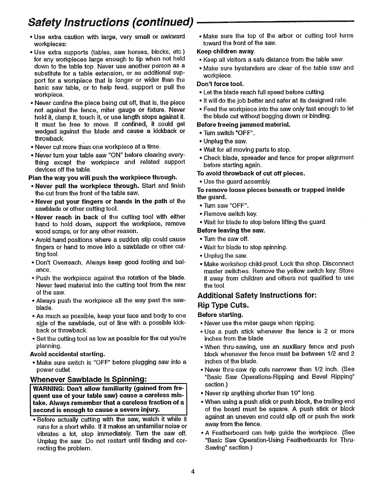
*Always use featherboards for any non thru rip type
cuts+
IJI 24'
_,, i _*_=.,_-.=. J==-...=o-
!
FEATHERBOARDS
•To avoid kickbacks and slips into the. blade, make sure
the rip fence is parallel to the sawblade.
° Before thru-sawing, check the anti-kickback pawls.
(See Basic _.aw Ope_t!o_l :,rU+slr!g3_ne,Rip Fence?'
- The pawls must stop a kickback_once it has started°
Replace or sharpen anti-kickback pawls when points
become dullo ++
°Plastic and composition (like hardboard) materials may
be cut on your saw+ However, since these are usually
quite hard and slippery, the anti-kickback pawls may
not stop a kickback. Therefore, be especially careful in
your setup and cutting procedures.
While thru-sawing.
.To avoid kickbacks and slips into the blade, always
push forward on the section of the workpiece between
the sawblade and the rip fence. Never push forward on
the piece being cut off.+
Additional Safety Instructions For:
Crosscut Type Cuts.
Before starting.
•Never use the rip fence whan crosscutting.
oAn auxiliary wood facing attached to the miter gauge can
help prevent work'piece twisting and throwbacks. Attach it
to the holes provided. Make the facing long enough and
big enough to support your work,, Make sure, however, it
will not interferewith the sawblade guard.
oUse jigs or fixtures to help hold any piece too small to
extend across the full length of the miter gauge face
during the cut. This lets you properly hold the miter
gauge and workpiece and helps keep your hands away
from the blade.
While cutting.
° To avoidblade contact,always ho_ the mitergauge as shown
in "BasicSaw Operations-Using The Miter Gauge".
Glossary of Terms for Woodworking ......................
Anti=Kickback Pawls (AKP i
Device which when properly maintained is designed to
.• +'. ,t + ,, ,!+._,.....
stop the workp_ece from being kicked back at the opera-
tor during ripping operation.
Arbor
The shaft on which a cuttingtool is mounted+
Bevel Cut : +
An angle cutting operation made through the face of the
workpiece.
Compound Cut
A simultaneous bevel and miter crosscutting operation..
Crosscut
Acutting operation made across the width of the work-
piece°
Dado
A non thru cut which produces asquare sided notch or
trough in the workpiece.
Featherboard
Adevice which can help guide workpieces during rip type
operation. .,
Freehand
Performing a cut without the use Of fence (guide), miter'
gauge, fixture, hold downior 0the! p+roper device to pre-
vent the workpiece from twisting during the cutting opera-
tion. Twisting of the wo_piece can cause _tto be thrown.
Gum , .... ., :
A sticky, sap based residue from wood products,,
Heel ,.
Misa+ignment of the sawblade such that the blade is not
parallel to the miter gauge groove..
Kerr
The amount: of material removed by the blade in a
through cut. Also the slot produced by the blade in a non-
through or partial cut+
Kickback
An uncontrolled grabbing and throwing of the workpiece
back toward the front of the saw.
Leading End
The end of the workpiece which, during a rip type opera-
tion, is pushed intothe cutting tool first..
Miter Cut
An angle cutting operation made across the width of tile
workpiece.
Molding
A non through cut which produces a special shape in tile
workpiece used for joining or'decoration+
Push Stick
A device used to feed the workpiece through the saw dur-
ing narrow ripping type operations,. The push stick helps
keep tile operator's hands well away from the blade..
Push Block .+
Adevice used for' ripping type operations too narrow to
allow use of a push st!ck_ .
Rabbet
A notch inthe edge of a workpiece+
Resin
Asticky,sap based substance that has hardened.
Revolutions Per Minute (RPM)
The number' of turns completed by aspinning object in
one minute+
Glossary of Terms for Woodworking (continued) ............................
Rip Cut
A cutting operation along the length of the workpiece.
Sawblade Path
The area of the workpJece or table top directly in line with
either the travel of the blade or the part of the workpiece
which will be, or has been, cut by the blade..
Set
The distance that the tip of the sawblade tooth is bent (or
set) outward from the face of the blade.
Throw-Back
Throwing of pieces in a manner similar to a kickback.
Thru-Sawing
Any cutting operation where the blade extends com-
pletely through the thickness of the workpiece.
Trailing End
The workpiece end last cut by the blade in a ripping oper-
ation
Workpiece
The item on which the cutting operation is being per-
formed_ The surfaces of a workpiece are commonly
referred to as faces, ends, and edges_
Motor Specifications and Electrical Requirements
Power Supply and Motor Specifications
Tile AC motor used in this saw is auniversal, nonrevers-
ible type having the following specifications:
Maximum Developed HP ....................................................2-1/2
Voltage ........................................................................................;.............120
Amperes ..................................................................................................13
Hertz (Cycles) .........................................................................................60
Phase .................................................................................................Single
RPM .........................................................................................................4700
Rotation of Shaft ...............................................Countemlockwise
WARNING: To avoid electrical hazards, fire haz-
ards, or damage to the tool, use proper circuit pro-
tection. Your saw is wired at the factory for 120v
operation. Connect to a 120v, 15-amp branch circu it
and use a 15oamp time delay fuse or circuit breaker.
To avoid shock or' fire, if power cord is worn or cut,
or damaged in any way, have it replaced immedi-
ately.
Double Insulation
This tool is double insulated to provide a double thick_
ness of insulation between you and the tool's electrical
systern_ All exposed metal parts are isolated from the
internal metal motor components wifh protecting insula-
tion..
WARNING: Double insulation does not take the
place of normal safety precautions when operating
this tool.
DANGER: To avoid electrocution:
1. Use only identical replacement parts when ser-
vicing a tool with double insulation. Servicing
should be performed by aqualified service tech-
nician.
2. Do not expose to rain, use in damp location or
where floor is wet.
This tool is intended for indoor residential use only.
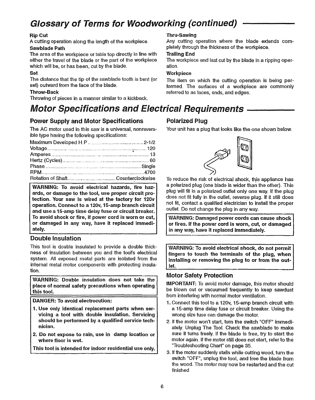
Polarized Plug
Your unit has a plug that looks like the one shown below.
To reduce the risk of electrical shock, tt_is appliance has
a polarized plug (one blade is wider than the other).. This
plug will fit in a polarized outlet only one way, If the plug
does not fit fulfy in the outlet, reverse plugo If it still does
not fit, contact a qualified electrician to install the proper
outlet.. Do not change the plug in any way.
or fires. If the power cord is worn, cut, or damaged
in any way, have it replaced immediately.
i WARNING: To avoid electrical shock, do not permit
fingers to touch the terminals of the plug, when
installing or removing the plug to or from the out-
let.
Motor Safety Protection
IMPORTANT: To avoid motor damage, this motor should
be blown out or vacuumed frequently to keep sawdust
from interfering with normal motor' ventilation.
1. Connect this tool to a 120v, 15-amp branch circuit with
a 15-amp time delay fuse or circuit breaker. Using the
wrong size fuse can damage the motor°
2. If the motor won't start, turn the switch "OFF" immedi-
ately_ Unplug The Tool Check the sawblade to make
sure it turns freely. If the blade is freel try to start the
motor again.. If the motor still does not start, refer to the
"Troubleshooting Chart" on page 35.
3. If the motor suddenly stalls while cutting wood, turn the
switch "OFF", unplug the tool, and free the blade from
the wood° The motor may now be restarted and the cut
finished
4._Fusesmay "blow"or circuitbreakersmaytrip fre_
quentlyif:
aMotor Is Overloaded. Ovedoading can occur' if you
feed too rapidly or' make too many start/stops in a
short time.
b.Voltages not more than 10% above or below the
nameplate voltage can handle normal loads. For
heavy loads, however, the voltage at motor terminals
must equal the voltage specified on nameplate.
Overload Protection
Your saw features a reset overload relay button. If the
motor stops running or fails to start (due to feed pres-
sure too fast, dull blade or' low voltage), turn switch
"OFF", let the motor cool three to five minutes and
push the reset button, which resets the overload
device and allows you to turn the saw back on.
WARNING: The ON/OFF switch should be in the off
position, and the plug removed from the power
source while the cool down takes place to prevent
accidental starting when the reset button is
pushed. Overheating may be caused by misaligned
parts or dull blade, Inspect your saw for proper
setup before using it again.
Table of Contents
5, Most motor tmubtes may be traced to loose or incor-
rect connections, overload, low voltage (such as small
size wire in the supply circuit) or to overly long supply
circuit wire.. Always check the connections, the load
and the supply circuit whenever motor' doesn't work
well Check wire sizes and lengttl with the Wire Size
Chart.
Wire Size
NOTE: Make sure the proper extension cord is used and
is in good condition°
The use of any extension cord will cause some loss of
power, To keep this to a minimum and to prevent over'-
heating and motor burnout, use the table to determine
the minimum wire size (A_W,G,.)extension cord.
Extension Cord Wire Sizes Required for 120V
Length (A.W.G.)
0-25 FL 14
26-50 FL 12
Warranty ..........................................................................................2
Safety Instructions for' Table Saw ....................................2-5
Glossary of Terms for Woodworking ...................................5-6
Motor Specifications & Electrical Requirements ............6-7.
Power Supply and Motor Specifications ..............................6
Double Insulation .................................................................................6
Polarized Plug .........................................................................6
Motor Safety Protection ....................................................6
Overload Protection .......................................................................7
Wire Size ...........................................................................................7
Unpacking and Checking Contents ...................................8-9
Tools Needed ..........................................................................................8
Table of Loose Parts ....................................................................8
List of Loose Parts .................................................................9
Assembly, Alignment and Adjustment ............................9-18
Assembling Handle to Handwheel ........................................9
Blade Guard Assembly ......................................................10
Blade Guard Alignment ................................................................1t
Checking Anti-kickback Pawls ..........................................11
Rip Fence Assembly and Adjustment ............................12
Rip Fence Alignment ...................................................................... 12
Rip Fence Indicator' Adjustment ..........................................13
Miter Gauge and Indicator Adjustment ...............................13
On-Off Switch ........................................................................13
Blade Tilting Control and Lock Lever Adjustment ...........14
Adjusting 90 and 45 Degree Positive Stops ......................14
Adjusting Positive Stops at 90 Degrees ................... 14
Adjusting Positive Stops at 45 Degrees ................... 14
Blade Tilt Indicator Adjustment ............................................15
Checking Blade Parallel to Miter' Gauge Groove ...........15
Adjusting Blade Parallel to Miter Gauge Groove ........ 16
Removing Sawbiade .............................................................16
Installing Sawblade .................................................................17
Mounting Table Saw to Workbench, Cabinet
or Legset ......................................................................17-18
Getting to Know Your Table Saw ......................................19-20
Work Feed Devices .............................................................21
Push Stick .......................................................................................21
Push Block .......................................................................21-22
Auxiliary Fence ..........................................................................22
Safety Instructions for Basic Saw Operations ........ 23-24
Basic Saw Operations .........................................................25-32
Using the Miter' Gauge .......... :.............................................25
Additional Safety Instructions for Crosscutting .........25
Crosscutting ....................................................................................25
Repetitive Crosscutting .................................................26
Miter Crosscutting ........................................................26
Bevel Crosscutting ..........................................................................26
Compound Miter Crosscutting ......................................27
Using tile Rip Fence ........................................................27
Additional Safety Instructions for Rip Cuts ..................27
Ripping ...............................................................................28
Bevel Ripping ......................................................................29
Using Featherboards for Thru-Sawing ......................................30
Resawing ............................................................................30
Using Featherboards for' Non Thru-Sawing ..................31
Dadoing ...........................................................................31
Rabbeting .................................................................... 32
Ploughing and Molding ....................................................32
Installation and Operation of Molding Head .............. 33
Maintaining Your Table Saw ............................... 33-34
Maintenance .......................................................................33
Lubrication .................................................................................... 34
Sears Recommends the Following Accessories ........34
Troubleshooting ......................................................................35
Repair Parts .....................................................................36-41

Unpacking and Checking Contents
Tools Needed
#2 Phillips Screwdriver
Combination Square
Combination Square must be true. Check its
accuracy as shown below.
Draw light line on board
alon edge
Select the straight edge of
314" thick board, This edge
must be perfectly straight,
Medium Screwdriver
__-_ii, ----L _.--__
Adjustable Wrench
[_L_.L! r _ I._.Lj
Straight Edge
Should be no gap or overlap
here when square is flipped
over in dotted position
NOTE: The square and
straight edge are used
to align the saw,
They must be accurate
if the saw is to be
aligned properly.
Separate all parts from packing material and check each
one with the illustration and the list of Loose Parts to
make certain all items are accounted for, before discard-
ing any packing material.
WARNING: If any parts are missing, do not attempt
to assemble the table saw, plug in the power cord l
or turn the switch on until the missing parts are
obtained and are installed correctly _
Table of Loose Parts
Item Description Qty
A Table Saw Assembly .....................................................1
BMiter Gauge ......................................................................1
C Blade Guard and Spreader ......................................1
D Rip Fence (Without Handle) .................................1
E Owner's Manual ................................................................t
F Bag of Loose Parts ........................................................*
*Number varies; bags can contain other smaller bags..
Loose parts within a bag may be pro-assembled at fac-
tory to ensure proper contents, The parts may need to be
disassembled when checking the contents against the
loose parts lisL
NOTE: To make assembly easier keep contents of each
bag together and separate from contents of other bags.
Apply a coat of automobile wax to the table. Wipe all
parts thoroughly with a clean, dry cloth, This will reduce
friction when pushing workpiece.. ....
l WARNiNG: "F'or your own safety, never connect
_plug to power source _outlet iantil all assembly
j steps are complete, and you have read and under-
[stand the safety and operating instructions,
B
A
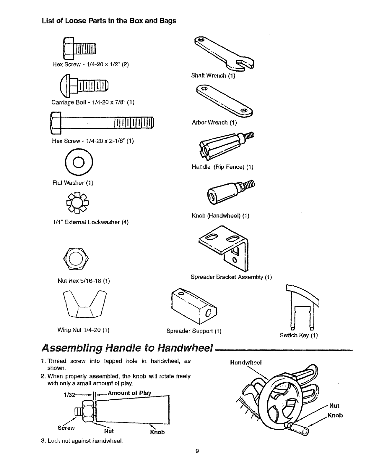
List of Loose Parts in the Box and Bags
He)( Screw - 1/4-20 x I/2" (2)
Carriage Bolt -1/4-20 x 7/8" (1)
..... , Ii,[,!lllllJl ilt;
He× Screw _ 1/4-20 x 2-1/8" (1)
Flat Washer' (1)
©
114" External kockwasher (4)
Shaft Wrench (1)
Arbor' Wrench (1)
Handle (Rip Fence) (1)
Knob (Handwheel) (1)
Nut Hex 5/16-18 (!)
Wing Nut 1/4-20 (I)
Spreader Bracket Assembly (1)
Spreader Support (1) Switch Key (1)
Assembling Handle to Handwheel .......................
1.Thread screw into tapped hole in handwheel, as
shown.
2oWhen properly assembled, the knob will rotate freely
with only a small amount of play.
Handwheel
3. Lock nut against handwheel
Nut

Blade Guard Assembly .......... ' ......
1. Frorn amongthe loose parts, locate the folk_wirlghardware:
Hex Screw -
114-20 x 1/2" (2)
©
1/4" External
Lockwasher (4)
Carriage Bolt -1/4-20 x 7/8" (1)
Q
Flat Washer (1) Wing Nut 114-20 (1)
Hex Screw - 1/4-20 x 2-1/8" (1)
G
Spreader Support/1) Spreader Bracket (1)
2. Position large recessed shoulder end of the
spreader support against end of pivot rod and fas-
ten to table using the 1/4-20x2-1/8" long hex screw
and 1/4" external tooth Iockwasher.
Recessed / /.'f /
/ 2 8ackof
"'Pivot Rod
_ _asher 1/4"
Screw ,,
1/4-20 x 2-1/8
3_ Position the spreader bracket to the spreader sup-
port as shown The 1/4-20xl/2" screws and lock-
washers are to be assembled finger' tight only at this
time.
4_ Insert the 1/4-20 x 7/8" carriage bolt in the square
feature of the spreader bracket as shown. Assemble
the fiat washer first, then the 1/4 external Iockwasher
and the 1/4-20 wing nut on the carriage bolt leaving
the wing nut loose at this time.
5, Attach bIade guard and spreader by positioning the
open slot in the spreader directly above the spreader'
brackeL Slide the spreader down between the
spreader bracket and the head of the rivet until either
the open slot sets on the rivet or the spreader sets
on the table top sudace. Tighten wing nut.
NOTE: Both wash'ers must be positioned between the
spreader' and the wing nut,,
Spreader
Win Nut
Carriage Belt
1/2-20x7/8
10
ii IIII,Mlll ,,I,I
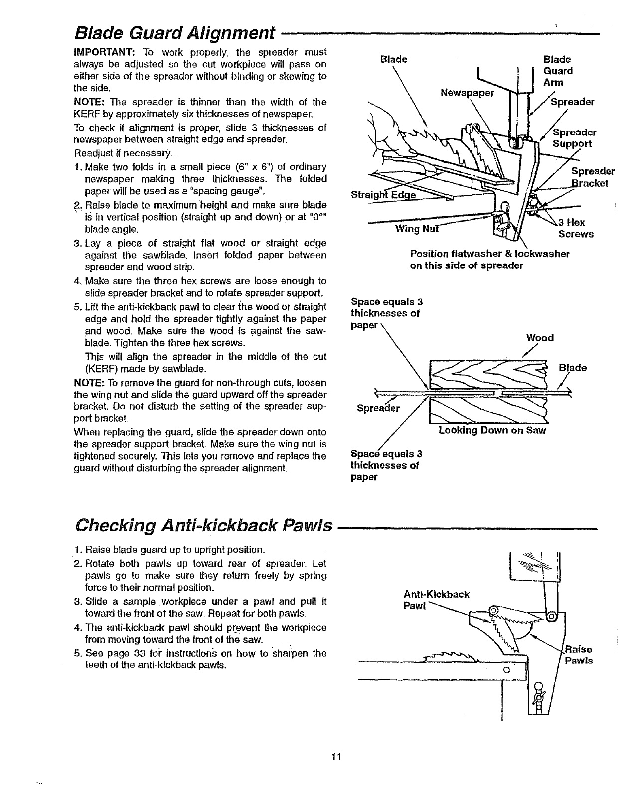
Blade Guard Alignment
IMPORTANT: To work properly, the spreader must
always be adjusted so the cut workpiece will pass on
either'side of the spreader without binding or'skewing to
the side.
NOTE: The spreader' is thinner than the width of the
KERF by approximately six thicknesses of newspaper,
To check if alignment is proper, slide 3 thicknesses of
newspaper between straight edge and spreader:
Readjust if necessary,
1,,Make two folds in a small piece (6" x 6") of ordinary
newspaper' making three thicknesses. The folded
paper' will be used as a "spacing gauge'S
2. Raise blade to maximum height and make sure blade
"is in vertical position (straight up and down) Or at "0°"
blade angle.
3. Lay apiece of straight flat wood or straight edge
against the sawblade,, Insert folded paper between
spreader and wood strip.
4. Make sure the three hex screws are loose enough to
slide spreader bracket and to rotate spreader' support,.
5, Lift the anti-kickback pawl to clear the wood or straight
edge and hold the spreader tightly against the paper
and wood,, Make sure the wood is ,against the saw-
blade,,Tighten the three hex screws.
This will align the spreader in the middle of the cut
(KERF) made by sawblade.
NOTE: To remove the guard for non-through cuts, loosen
the wing nut and slide the guard upward off the spreader
bracket,. Do not disturb the setting of the spreader' sup-
portbracket.
When replacing the guard, slide the spreader' down onto
the spreader support bracket.. Make sure the wing nut is
tightened securely.. This lets you remove and replace the
guard without disturbing the spreader alignment.
Blade Blade
Guard
Arm
Strai!
Spreader'
Wing ,tex
Screws
Position flatwasher & Iockwasher
on this side of spreader
Space equals 3
thicknesses of
/Looking Down on Saw
/
Space equals 3-
thicknesses of
paper
Checking Anti-kickback Pawls,
1. Raise blade guard up to upright position..
2. Rotate both pawls up toward rear of spreader° Let
pawls go to make sure they return freely by spring
force to their normal position.
3. Slide a sample workpiece under a pawl and pull it
toward the front of the saw_Repeat for both pawls.
4. The anti-kickback pawl should pr+event the workpiece
from moving toward the front of the saw.
5oSee page 33 foi+instructions on how to sharpen the
teeth of the anti-kickback pawls.
"a'j"+"+°°" T
:laise
Pawls
11

Rip Fence Assembly and Adjustment ...........................
iWARNING: To prevent personal injury, always dis- i
lconnect plug from power source when making I
adjustments.
1. Thread 5/16-18 nut all the way onto the fence locking
handle
2, Thread rip fence locking handle into cam until tight,,
Lock the nut against cam with wrench,
3Place the rip fence on the table and lower' the rip fence
locking handle until the rip fence is secure to front rail.
4. Check to see if rear' clamp on the rip fence is loose,. If
not, turn the rip fence adjustment screw counterclock-
wise until the rear clamp on the rip fence is loose with
the fence assembly locked to the front rail,
5, With fence assembly locked to front rail, turn the rip
fence adjustment screw clockwise until rear clamp is
snug.
6, Raise the rip fence locking handle.
7,.Turn the rip fence adjustment screw clockwise an addi-
tional 1/2 turn.
8. Check the rip fence by applying moderate side pres-
sure to the rear ef the fence assembly, If the rip fence
deflects easily raise the rip fence locking handle and
turn the rip fence adjustment screw clockwise another
1/4 turn.
9. Check rip fence again by applying moderate side pres-
sure to the rear of the fence assembly. If necessary
repeat step 8 until rip fence is secure.
NOTE: Overtightening the rip fence adjustment screw
may cause the rip fence to be loose on the front table rail.
Rip Fence Alignment ..................
jWARNING: To prevent personal injury, always dis- I
m
connect plug from power' source when making
adjustments.
i CAUTION: The rip fence must be aligned parallel to I
'1the blade to minimize the danger of kickback. For }
}convenience, the rip fence will be aligned parallel
Ito the miter gauge slot. The sawblade will be set or I
1adjus!ed parallel to the slot later. !
1,.Place the rip fence on the right side of the table adja-
cent to the miter gauge groove,.
2. Lower the rip fence locking handle to secure the rip
fence.
3. Check to see that the edge of the rip fence is parallel
with the miter gauge groove.
4. If the rip fence is not parallel:
oRaise the rip fence locking handle.
• Loosen the two hex head screws located on top of
the rip fence,.
oAlign the rip fence parallel to the miter gauge groove.
oLower the rip fence locking handle,,
• Tighten the two hex head screws previously loos-
ened,
Q
Nut Hex 5/16-18 (1)
Adjustment
Handle (Rip Fence) (1)
/
Miter Gauge
ut Fence
/Locking
Rear Clamp
o
Rip Fence
Adjusting Screws
!2
° Raisethe ripfencelockinghandle,moveandreturn
the nipfenceadjacentto the mitergaugegroove,
lower'theripfencelockinghandle.
•Repeatandrechecksteps8 and9 inthe"RipFence
Assemblyand Adjustment" sectien_
• The rip fence should now be parallel to the miter
gauge groove.. If not, repeat steps and recheck
NOTE: To always obtain tile best atignment'of the 'rip
fence, develop the habit of holding the front casting on
the fence back against the table top while tightening the
fence tock handle Tigilten the rip fence lock handle
securely to prevent rip fence movement while sawing.
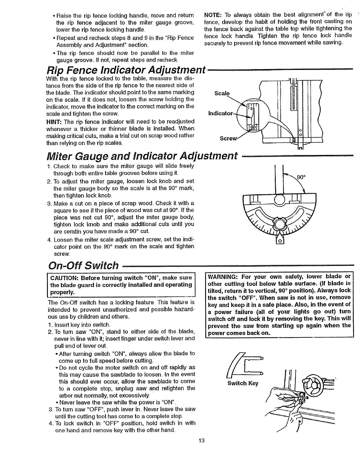
Rip Fence Indicator Adjustment .......
With the rip fence locked to the table, measure the dis-
tance from the side'of the rip fence to the nearest side of
the blade.. The indicator should point to the same marking
on the scale. If it does not, loosen the screw holding the
indicator; move the indicator to the correct marking on the
scale and tighten the screw.
HINT; The dp fence indicator will need to be readjusted
whenever a thicker or thinner' blade is installed. When
making critical cuts, make a trial cut on scrap wood rather
than relying on tile rip scales.
Scal_
screw (
Miter Gauge and Indicator Adjustment
1. Check to make sure the miter' gauge will slide freely
through both entire table grooves before using it.
2. To adjust the miter gauge, loosen lock knob and set
the miter gauge body so the scale is at the 90° mark,
then tighten lock knob.
3. Make a cut on a piece of scrap wood.. Check it with a
square to see if the piece of wood was cut at 90% If the
piece was not cut 90°, adjust the miter gauge body,
tighten lock knob and make additional cuts until you
are ceratin you have made a 90° cut..
4. Loosen the miter scale adjustment screw, set the indi-
cator point on the 90°mark on the scale and tighten
screw.
lUUlU,ii
90°
On-Off Switch
lc.° io.;oo,o.o,um,°0ow.c.o.., o.ol
the blade guard is correctly installed and operating
properly.
The On-Off switch has a locking feature. This feature is
intended to prevent unauthorized and possible hazard-
ous use by children and others..
1. Insert key into switch.
2. To turn saw "ON", stand to either side of the blade,
never in line with it; insert finger under switch lever and
pull end of lever out..
oAfter' turning switch "ON", always allow the blade to
come up to full speed before cutting
oDo not cycle the motor switch on and oft rapidly as
this may cause the sawblade to loosen. In the event
this should ever occur, allow the sawblade to come
to a complete stop, unplug saw and retighten the
arbor' nut normally, not excessively "
°Never leave the saw while the power is "ON".
3_To turn saw "OFF", push lever in. Never leave the saw
until the cutting tool has come to a complete stop.
4..To lock switch in "OFF" position, hold switch in with
one hand and remove key with the other hand
WARNING: For your own safety, lower blade or
other cutting tool below table surface. (If blade is
tilted, return it to vertical, 90 ° position). Always lock
the switch "OFF". When saw is not in use, remove
key and keep it in a safe place. Also, in the event of
a power' failure (all of your lights go out) turn
switch off and lock it by removing the key. 'This will
_revent the saw from starting up again when the
}ower comes back on.
Switch Key
13
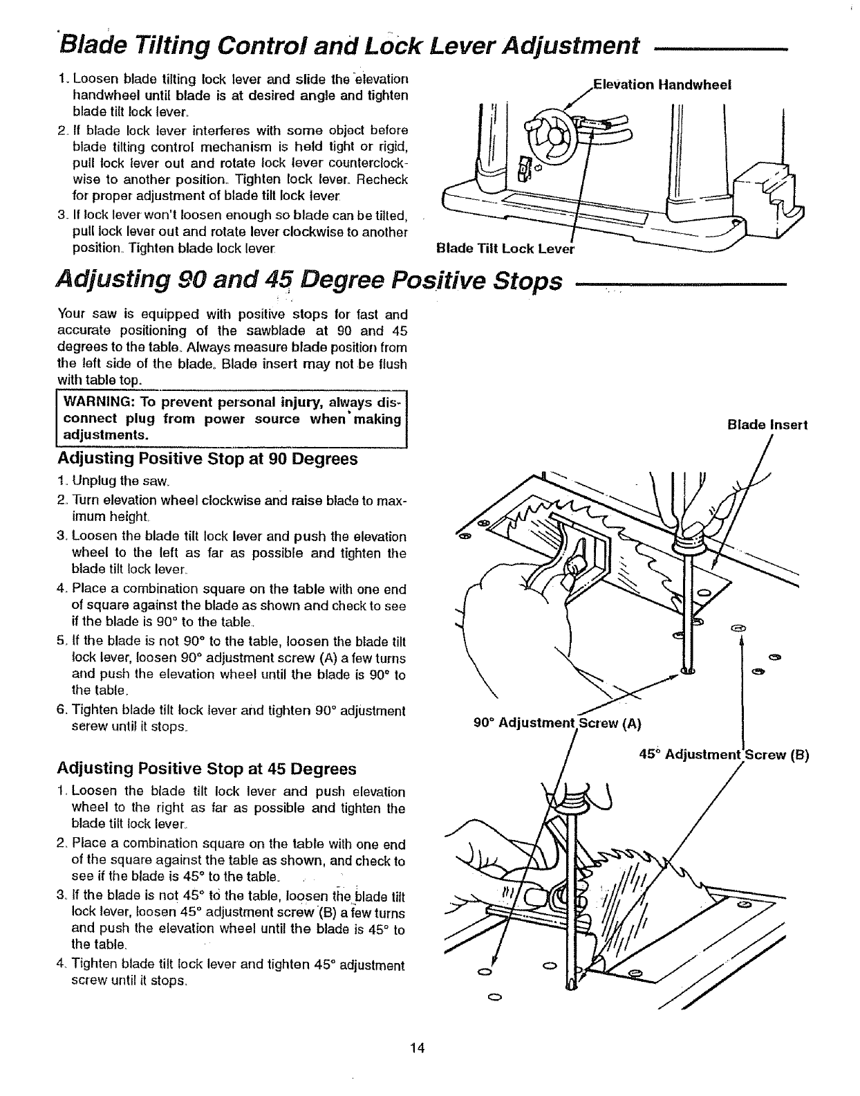
Blade Tilting Control and LOck Lever Adjustment
1. Loosen blade tilting lock lever and slide the _eievation
handwheel until blade is at desired angle and tighten
blade tilt locklever_
2. If blade lock lever' intederes with sorne object before
blade tilting control mechanism is held tight or rigid,
pull lock lever out and rotate lock lever counterclock-
wise to another position.. Tighten lock lever..Recheck
for proper adjustment of blade tilt lock lever
3_ If rock lever won't loosen enough so blade can be tilled,
pull lock lever out and rotate lever clockwise to another
position,. Tighten blade lock lever
iiiiiiii ii iii ,i,
.Elevation Handwheei
!1
Blade Tilt Lock Lever
Adjusting 90 and 45 Degree Positive Stops
Your saw is equipped with positive stops for fast and
accurate positioning of the sawblade at 90 and 45
degrees to the table.. Always measure blade position from
the left side of the blade,. Blade insert may not .be flush
with table top.
WARNING: To prevent personal injury, always dis-
connect plug from power source when making
adjustments.
Adjusting Positive Stop at 90 Degrees
1_Unplug the saw.. "_"
2. Turn elevation wheel clockwise and raise blade to max-
imum height,
3o Loosen the blade tilt lock lever and push the elevation
wheel to the left as far as possible and tighten the
blade tilt lock lever..
4. Place a combination square on the table with one end
of square against the blade as shown and checkto see
if the blade is g0° to the table.,
5,.If the blade is not 90 ° to the table, loosen the blade tilt \
lock lever, loosen 90° adjustment screw (A) a few turns
and push the elevation wheel until the blade is 90° to
the table.
6. Tighten blade tilt lock lever and tighten 90° adjustment
serew until it stops..
r i
90° Adjustment Screw (A)
Adjusting Positive Stop at 45 Degrees
1..Loosen the blade tilt lock lever and push elevation
wheel to the right as far as possible and tighten the
blade tilt lock lever.
2.. Place a combination square on the table with one end
of the square against the table as shown, and check to
see if the blade is 45" to the table.
3o tf the blade is not 45 ° t0 the table, loosen the blade tilt
lock lever, loosen 45 ° adjustment screw(B) a {ew turns
and push the elevation wheel until tile blade is 45° to
the table.
4. Tighten blade tilt lock lever and tighten 45 ° adjustment
screw until it stops..
Blade Insert
45 _Adjustmen Screw (B)
14
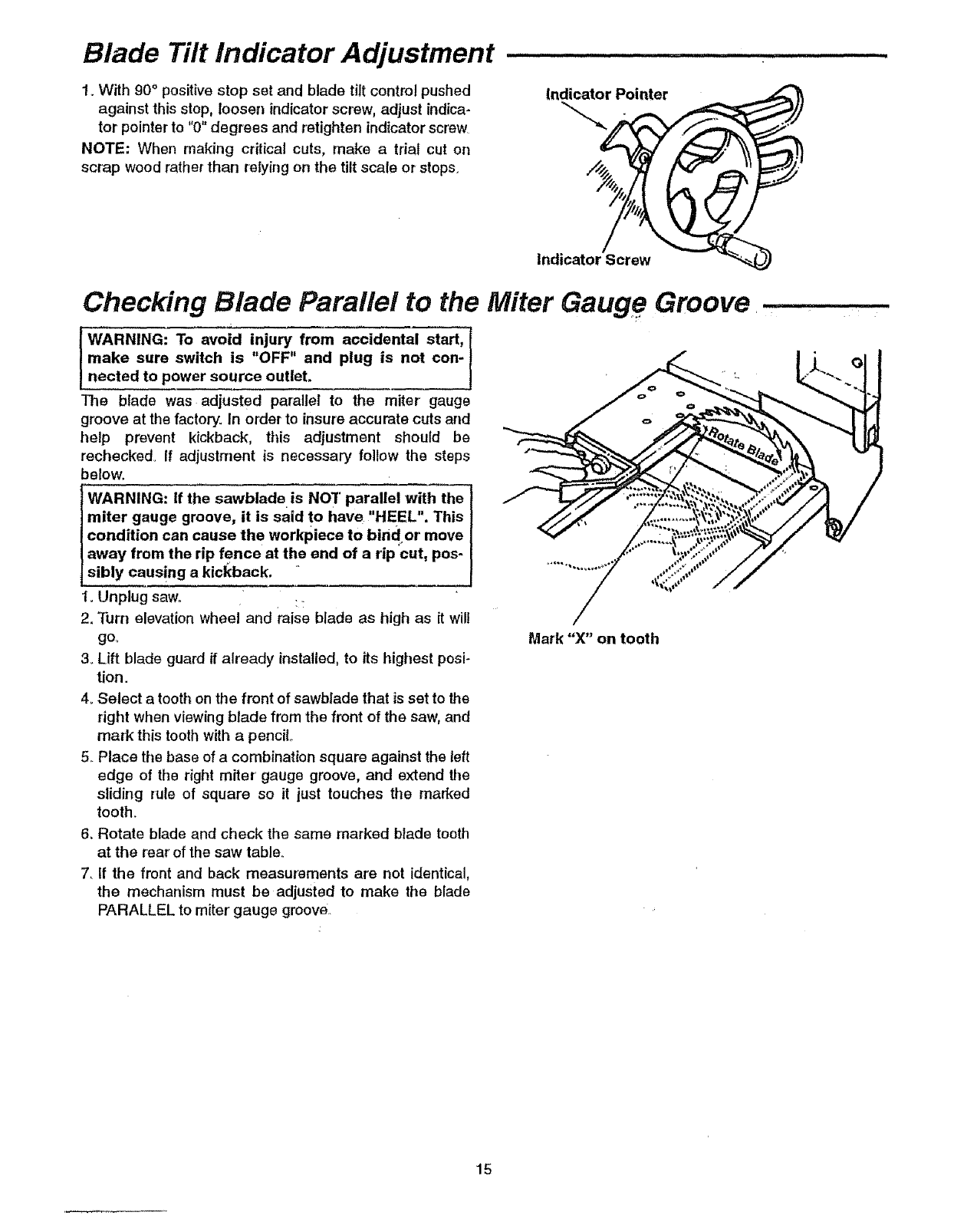
Blade Tilt Indicator Adjustment
1. With 90 ° positive stop set and blade tilt control pushed
against this stop, loosen indicator screw, adjust indica-
tor pointer to "0" degrees and retighten indicator screw
NOTE: When making critical cuts, make a trial cut on
scrap wood rather than relying on the tilt scale or stops.
Indicator Pointer
Indicator Screw
Checking Blade Parallel to the Miter Gauge Groove
I WARNING: To avoid injury, from accidental start, t
make sure switch is OFF' and plug is not con-
nected to power source outlet.
The blade was adjusted parallel to the miter gauge
groove at the factory. In order to insure accurate cuts and
help prevent kickback, this adjustment should be
rechecked° If adjustment is necessary follow the steps
below.
tWARNING: If the sawblade is NO7' parallel with the
]miter gauge groove, it is said to have "'HEEL". This
condition can cause the workpiece to birid or move
away from the rip fence at the end of a rip cut, pos-
[sibly causing a kickback.
1oUnplug saw., ::
2. Turn elevation wheel and raise blade as high as it will
go_
3oLift blade guard if already installed, to its highest posi-
tion ..
4oSelect a tooth on the front of sawblade that is set to the
dght when viewing blade from the front of the saw, and
mark this tooth with a pencil
5. Place the base of acombination square against the left
edge of the right miter' gauge groove, and extend the
sliding rule of square so it just touches the marked
tooth.
6, Rotate blade and check the same marked blade tooth
at the rear'of the saw table.
7. tf the front and back measurements are not identical,
the mechanism must be adjusted to make the blade
PARALLEL to miter gauge groove.
Mark "X" on tooth
15
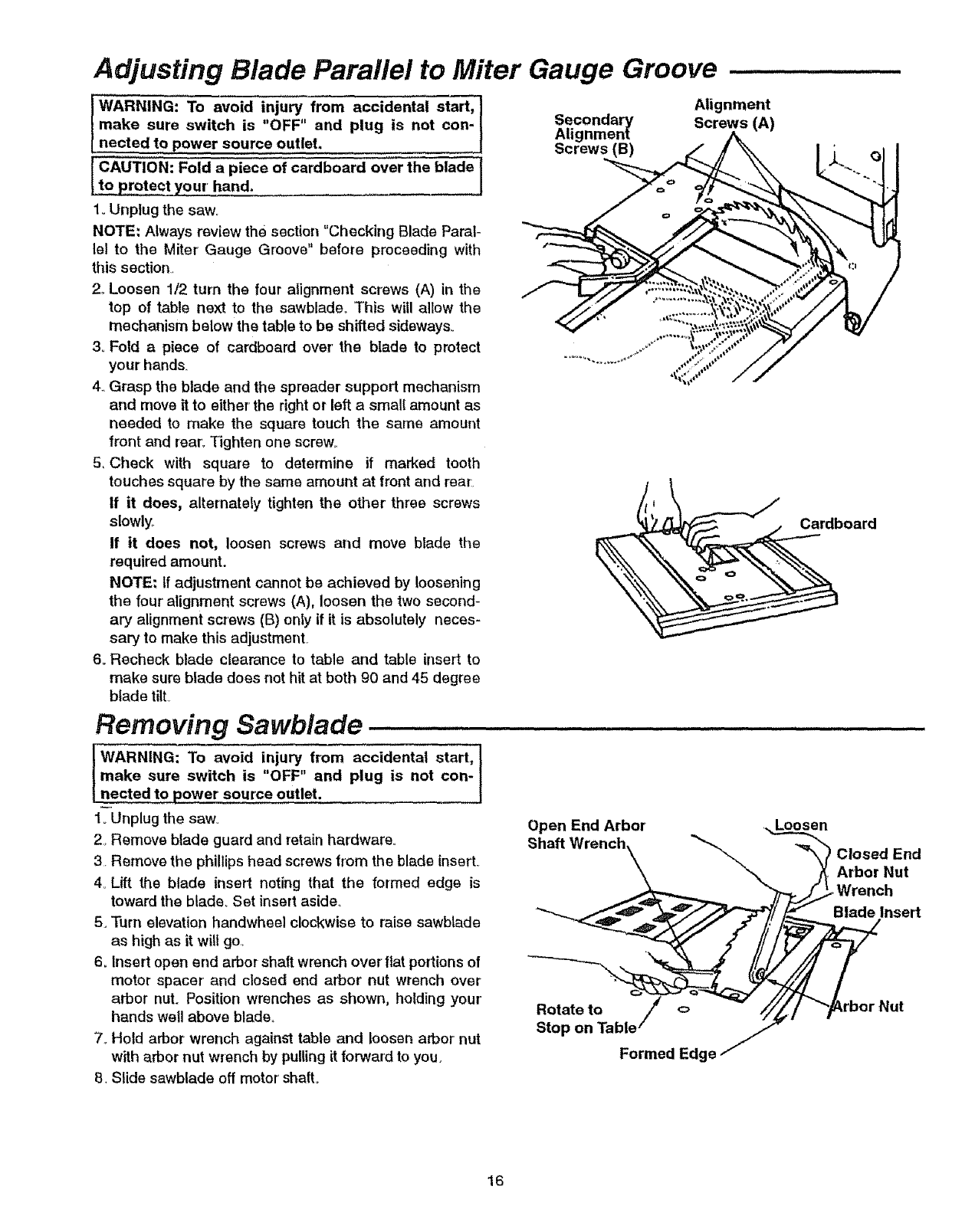
Adjusting Blade Parallel to Miter Gauge Groove
IWARNING: To avoid injury from accidental start,]
make sure switch is "OFF" and plug is not con-I
netted to power source outlet. f
CAUTIoN: Fold a piece of cardboard over the blade j
d. I
1.,Unplug the saw.,
NOTE: Always review the section "Checking Blade Paral_
lel to the Miter Gauge Groove" before proceeding with
this section,
2, Loosen 1/2 turn the four alignment screws (A) in the
top of table next to the sawblade.. This will allow the
mechanism below the table to be shifted sideways°
3, Fold a piece of cardboard over' the blade to protect
your hands_
4.,Grasp the blade and the spreader support mechanism
and move it to either' the right or left a small amount as
needed to make the square touch the same amount
front and rear. Tighten one screw.
5, Check with square to determine if marked tooth
touches square by the same amount at front and rear.
If it does, alternately tighten the other three screws
slowly.
If it does not, loosen screws and move blade the
required amount.
NOTE: If adjustment cannot be achieved by loosening
the four alignment screws (A), loosen the two second-
ary alignment screws (B) only if it is absolutely neces-
sary to make this adjustment,
6. Recheck blade clearance to table and table insert to
make sure blade does not hit at both 90 and 45 degree
blade tilt.
Secondary
Alignment
Screws (B)
illllll
Alignment
Screws (A)
oard_
Removing Sawblade
WARNING: To avoid injury from accidental start, !
make sure switch is "OFF" and plug is not con- t
nected to power source outlet.
l_Unplug the saw_
2. Remove blade guard and retain hardware°
3. Remove the phillips head screws from the blade insert.
4. Lift the blade insert noting that the formed edge is
toward the blade_ Set insert aside._
5. Turn elevation handwheel clockwise to raise sawblade
as high as it w{!l go..
6. Insert open end arbor shaft wrench over ttat portions of
motor spacer' and closed end arbor' nut wrench over
arbor nut. Position wrenches as shown, holding your'
hands well above blade°
7oHold arbor wrench against table and loosen arbor'nut
with arbor nut wrench by pulling it forward to you.
B. Slide sawblade off motor shaft°
Open End Arbor' .L._oosen
Shaft Wrench\ "_'-_._ ._-_ Closed End
.Arbor Nut
Wrench
---. .,
Stop on Table _" /
/
Formed Edge
16
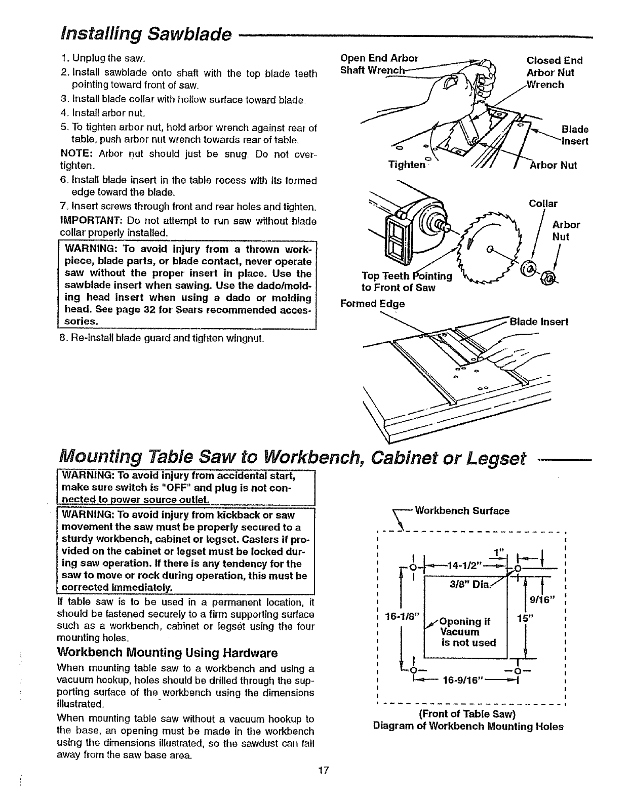
Installing Sawblade
1..Unplug the saw.
2_Install sawblade onto shaft with the top blade teeth
pointing toward front of saw_
3. Install blade collar with hollow surface toward blade
4. Install arbor nut..
5_To tighten arbor nut, hold arbor' wrench against rear of
table, push arbor nut wrench towards rear of table.
NOTE: Arbor nut should just be snug.. Do not over-
tighten.
6, Install blade insert in the table recess with its formed
edge toward the blade.
7..Insert screws through front and rear holes and tighten_
IMPORTANT: Do not attempt to run saw without blade
coUar properly installed.
WARNING: To avoid injury from a thrown work-
piece, blade parts, or blade contact, never operate
saw without the proper insert in place. Use the
sawblade insert when sawing. Use the dado/mold-
ing head insert when using a dado or molding
head. See page 32 for Sears recommended acces-
sories.
8. Re-install blade guard and tighten wingnuL
,H=HH = =
Open End Arbor
__ Arbor Nut
Shaft Wrench_--"-_'_--_, i_ Closed End
Wrench
Blade
_"lnsert
Tighten- _/'/ /Arbor Nut
To! inting
to Front of Saw
Formed Edge
Collar
Arbor
Nut
Insert
Mounting Table Saw to Workbench, Cabinet or Legset
WARNING: To avoid injury from accidental start,
make sure switch is "OFF" and plug is not con-
nected to power source outlet.
WARNING: To avoid injury from kickback or saw
movement the saw must be properly secured to a
sturdy workbench, cabinet or legset. Casters if pro-
vided on the cabinet or legset must be locked dur-
ing saw operation, if there is any tendency for the
saw to move or'rock during operation, this must be
corrected immed!ately.
If table saw is to be used in a permanent location, it
should be fastened securely to afirm supporting surface
such as aworkbench, cabinet or legsbt using the four'
mounting holes.
Workbench Mounting Using Hardware
When mounting table saw to a workbench and using a
vacuum hookup, holes should be drilled through the sup-
porting surface of the workbench using the dimensions
illustrated
When mounting table saw without avacuum hookup to
the base, an opening must be made in tile workbench
using the dimensions illustrated, so the sawdust carl fall
away from the saw base area..
--- Workbench Surface
I
I1'___'
'__Ot_._--14.112,,___
' i I ;¢8';viaF
16-1/8" _Opening if
oI Vacuum
is not used
I
I-.=--- 16-9/16" _
15"
(Front of Table Saw)
Diagram of Workbench Mounting Holes
17
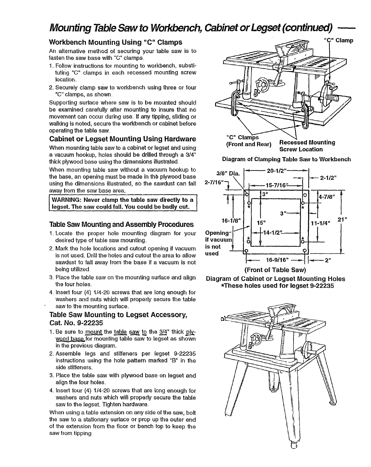
Mounting TableSaw to Workbench,Cabinetor Legset(continued)
Workbench Mounting Using "C" Clamps
An alternative method of securing your table saw is to
fasten the saw base with "C" clamps._
1. Follow instructions for mounting to workbench, substi-
tutirig "C" clamps in each recessed mounting screw
Iocation_
2. Securely clamp saw to workbench using three or four
"C" clamps, as shown.
Supporting surface where saw is to be mounted should
be examined carefully after mounting to insure that no
movement can occur during use.. If any tipping, sliding or
walking is noted, secure the workbench or cabinet before
operating the table saw.
Cabinet or Legset Mounting Using Hardware
When mounting table saw to a cabinet or tegset and using
a vacuum hookup, holes should be drilled through a 3/4"
thick plywood base using the dimensions illustrated.
When mounting table saw without a vacuum hookup to
the base, an opening must be made in th_ plywood base
using the dimensions illustrated, so the sawdust can fall
away from the saw base area.
WARNING: Never clamp the table saw directly to a l
legset. The saw could fall. You could be badly cut.
Table Saw Mounting and Assembly Procedures
1_Locate the proper hole mounting diagram for your
desired type of table saw mounting.
2_Mark the hole locations and cutout opening if vacuum
is not used. Drill the holes and cutout the area to allow
sawdust to fall away from the base if a vacuum is not
being utilized
3. Place the table saw on the mounting surface and align
the four holes..
4. insert four (4) 1/4-20 screws that are long enough for
washers and nuts which will properly secure the table
saw to the mounting surface.
Table Saw Mounting to Legset Accessory,
Cat. No, 9-22235
1. Be sure to mount the table _ to the 3/4" thick .p._-
_for mounting table saw to Iegset as shown
in the previous diagram..
2. Assembie legs and stiffeners per legset 9-22235
instructions using the hole pattern marked "B" in the
side stiffeners_
3oPlace the table saw with plywood base on legset and
align the four holes_
4_Insert tour (4) 1/4-20 screws that are long enough for
washers and nuts which wilt properly secure the table
saw to the legset. Tighten hardware..
When using a table extension on any side of the saw, bolt
the saw to a stationary surface or' prep up the outer end
of the extension from the floor or bench top to keep the
saw from tipping
"C" Clamps
(Front and Rear) Recessed Mounting
Screw Location
Diagram of Clamping Table Saw to Workbench
3/8" Dia.
16-1/8" 11-1/4" 21 "
Opening-
if vacuum
is not
used
16-9/16" _ 2"
(Front of Table Saw)
Diagram of Cabinet or Legset Mounting Holes
_These holes used for legset 9-22235
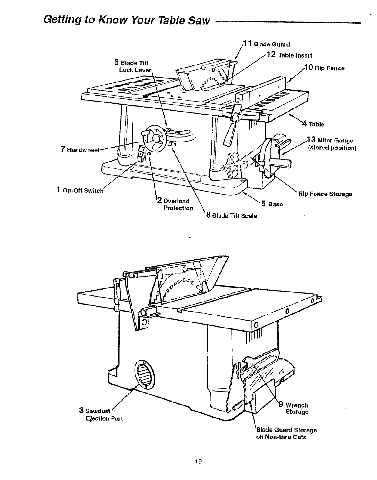
Getting to Know Your Table Saw ....
6Blade Tilt
11 Blade Guard
2Table Insert
Rip Fence
"4 Table
7Handwt
Miter Gauge
(stored position)
1 On-Off
Overload
Protection \8 Blade Tilt Scale
5 Base
Rip Fence Storage
3Sawdust F
Ejection Port
Wrench
Storage
Guard Storage
on Non-thru Cuts
19
Getting to Know Your Table Saw (continued) ...........
1. On-Off Switch.
ICAUTION: Before turning switch "oN;;; _
the blade guard is correctly installed and operating I
properly. I
The On-Off Switch has a locking feature, This feature is
intended to help prevent unauthorized and possible haz-
ardous use by children and others,,
2. Overload Protection
Your saw features an overload relay reset button° tf the
motor stops running or fails to start (due to feed pressure
too fast, dutl blade or' low voltage), turn switch =OFF"..
Unplug the saw° Let the motor cool three to five minutes
and push the reset button, which resets the overloaded
device and allows you to turn the saw back on.
WARNING: The on/off switch should be in the off J
position, and the plug removed from the power I
source while the cool down takes place to prevent I
accidental starting when the reset button is pushed. J
3. Sawdust Ejection Port
Your table saw is equipped with avacuum hookup°This fea-
ture will allow you to attach any standard 2-1/2 inch diame-
ter wet/dry vacuum hose into the hole provided for
convenient sawdust removal
WARNING: Sawdust can clog motor. Motor could]
ignite sawdust. Even if saw is connected to vac-
uum, blow out sawdust regularly.
4. Table
Provides large working surface to support workpiece_
5. Base
Supports table For additional stability, holes are provided
in base to bolt the saw to a workbench or stand_ \
6. Blade Tilt Lock Lever
Clamps the tilt mechanism after the blade is adjusted to
desired position. Use handwheel as a lever to tilt blade.
7. Handwheel
Elevates or'lowers the blade. Also used as a lever' to tilt
the blade from 0 to 45 degrees_
8. Blade Tilt Scale
Shows the degree the blade is tilted.
9. Wrench Storage
Conveniently stores shaft and arbor nut wrerlches.
10. Rip Fence
Exclusive self-aligning, quick-set rip fence can be easily
moved or locked in place by simply raising or lowering
lock handle. Holes are provided in the rip fence for
attaching a woad facing..
Select a piece of smooth straight wood approximately 3/4
inch thick, at least as along as the rip fence, and at least
7-1/2" wide (high) to permit clamping of featherboards
Attach it to the fence with two round head #10 wood
screws 1-5/8" long.
JWARNING: When positioning for'
fence maximum
rip, make sure end of fence head is even with the
edge of the table. Fence cannot be locked securely
beyond the edge of the table. The workpiece could
bind and kickback.
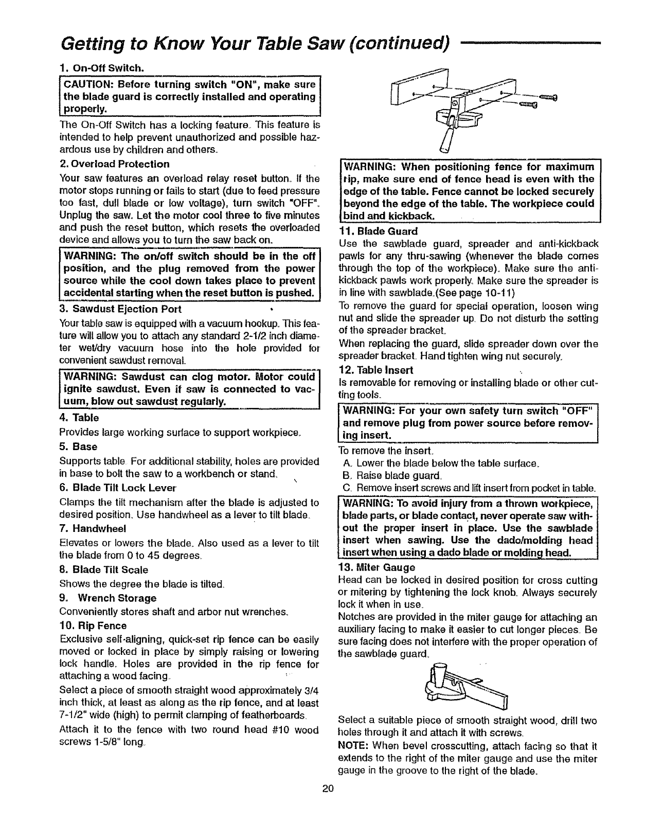
11. Blade Guard
Use the sawblade guard, spreader and anti-kickback
pawls for any thru-sawing (whenever the blade comes
through the top of the workplace). Make sure the anti-
kickback pawls work properly, Make sure the spreader is
in line with sawblade_(See page 10-11)
To remove the guard for special operation, loosen wing
nut and slide the spreader up, Do not disturb the setting
of the spreader' bracket°
When replacing the guard, slide spreader down over the
spreader bmcketo Hand tighten wing nut securely.
12, Table Insert
Is removable for removing or installing blade or other cut-
ting tools
JWARNING: For your 0wn safety turn switch "OFF" !
and remove plug from power source before remov-
ing insert.
To remove the insert.
Ao Lower the blade below the table surface_
BRaise blade guard
CRemoveinsertscrews and liftinsertfrompocketin table.
tWARNING: To avoid injury from a thrown workpiece,
blade parts, or blade contact, never operate saw with-
out the proper insert in place. Use the sawblade
insert when sawing. Use the dado/moiding head
insert when using a dado blade or moldin£1 head.
13. Miter Gauge
Head can be locked in desired position for cross cutting
or mitering by tightening the lock knob, Always securely
lock it when in use°
Notches are provided in the miter gauge for attaching an
auxiliary facing to make it easier to cut longer pieces° Be
sure facing does not interfere with the proper operation of
ttle sawblade guard,
Select a suitable piece of smooth straight wood, drill two
holes through it and attach it with screws_
NOTE: When bevel crosscutting, attach facing so that it
extends to the right of the miter gauge and use the miter
gauge in the groove to the rightof the blade
20
Work Feed Devices
Before cutting any wood on your saw. study all of the
"Basic Saw Operations" found on pages 23 through 33
As you learn new table saw woodworking techniques
you'll see that many types of cuts need different support
and feeding devices, known as jigs or fixtures. They can
help you make cuts more accurately By helping to steady
the workpiece and keep you away from the blade, they
can help you safely use,your saw for certain cuts.
Many people custom build their own jigs and fixtures Jigs
and fixtures are often designed for a particular cut.
You can use your table saw to easily make many jigs and
fixtures. To get you started, we've included instructions
for some simple ones. After you have made a few prac-
tice cuts, make up these jigs before starting any projects.
Make the push stick first
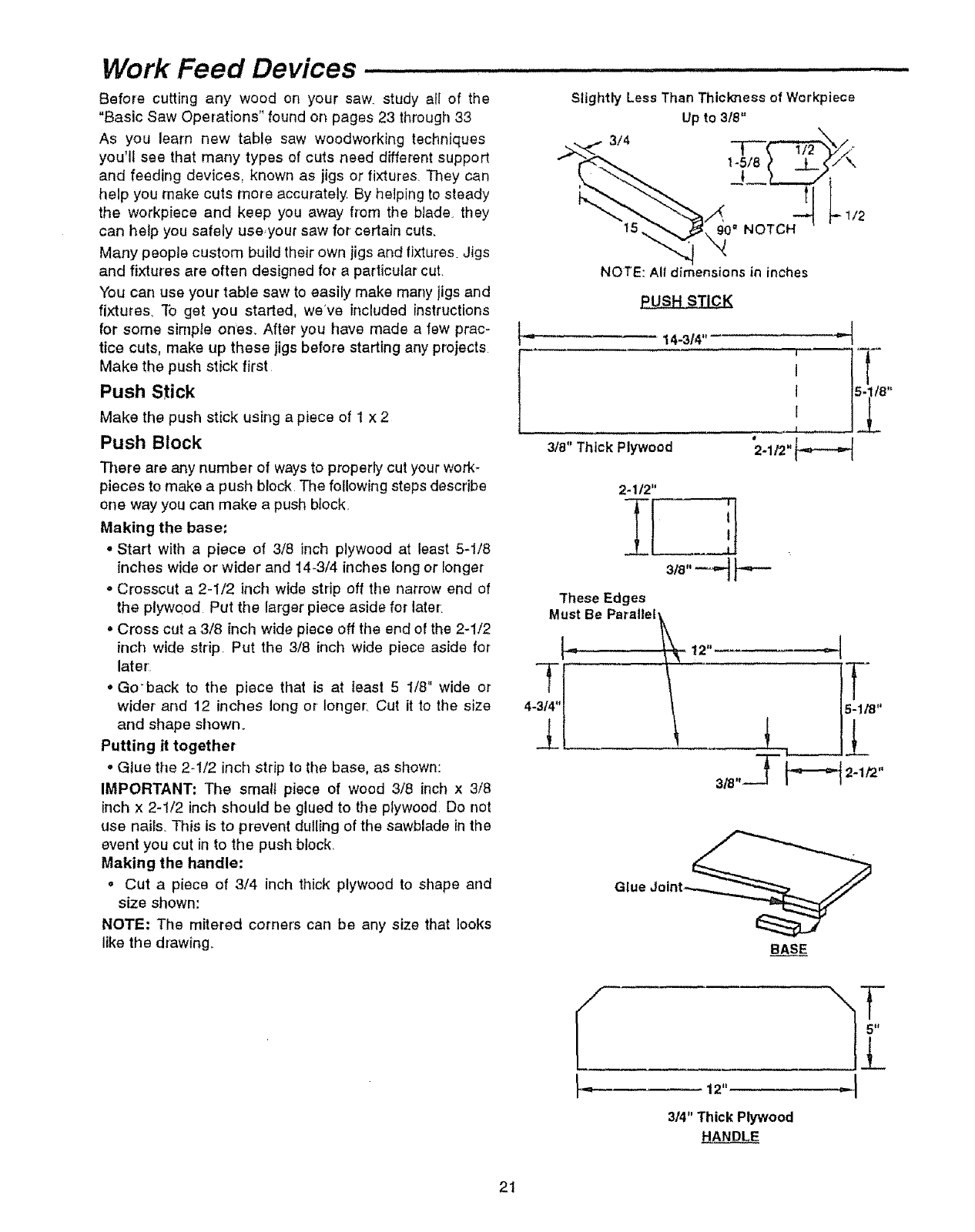
Push Stick
Make the push stick using a piece of 1 x 2
Push Block
There are any number of ways to properly cut your work-
pieces to make a push block. The following steps describe
one way you can make a push bfock
Making the base:
• Start with a piece of 3/8 inch plywood at least 5-1/8
inches wide or wider and 14-3/4 inches long or ionger
o Crosscut a 2-1/2 inch wide strip off the narrow end of
the plywood Put the larger piece aside for later.
oCross cut a 3/8 inch wide piece off the end of the 2-1/2
inch wide strip. Put the 3/8 inch wide piece aside for
later
,, Go'back to the piece that is at least 5 1/8" wide or
wider and 12 inches long or longer. Cut it to the size
arid shape shown.
Putting it together
oGlue the 2-1/2 inch strip to the base, as shown:
IMPORTANT: The small piece of wood 3/8 inch x 3/8
inch x 2-1/2 inch should be glued to the plywood Do not
use hales. This is to prevent dulling of the sawblade inthe
event you cut in to the push block.
Making the handle:
• Cut a piece of 3/4 inch thick plywood to shape and
size shown:
NOTE: The mitered corners can be any size that looks
like the drawing°
Slightly Less Than Thickness of Workpiece
Up to 318"
3/4
NOTE: A!! dimensions in inches
14"314" _"
I
I
I
I
J
2-1/2"
These Edges
Must Be Parallel
4- 5-1/8"
t
Glue Jolnt_
BASE
12,, --I
3/4" Thick Plywood
HANDLE
21
Work Feed Devices (continued) ......
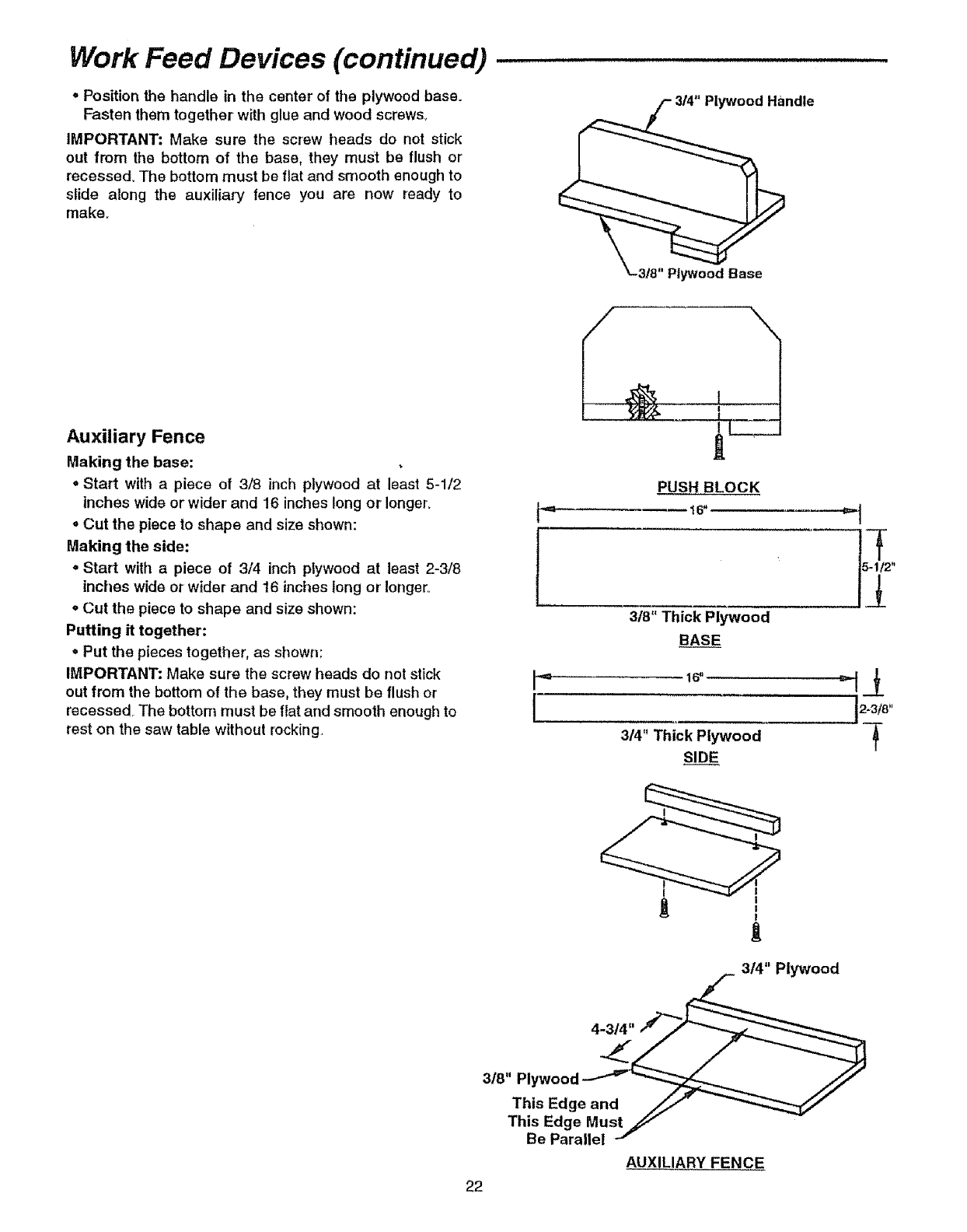
,Position the handle in the center of the plywood base.
Fasten them together with glue and wood screws_
IMPORTANT: Make sure the screw heads do not stick
out tram the bottom oi tile base, they must be flush or
recessed° The bottom must be flat and smooth enough to
slide along the auxiliary fence you are now ready to
make.
Auxiliary Fence
Making the base:
.Start with a piece of 3/8 inch plywood at least 5-1/2
inches wide or wider and 16 inches long or longer.
,Cut the piece to shape and size shown:
Making the side:
•Start with apiece of 3/4 inch plywood at least 2-3/8
inches wide or wider and 16 inches long or longer.
= Cut the piece to shape and size shown:
Putting it together:
.Put the pieces together, as shown:
IMPORTANT: Make sure the screw heads do not stick
out from the bottom of the base, they must be flush or
recessed.. The bottom must be Ilat and smooth enough to
rest on the saw table without rocking.
t
die
"t-3/8" Plywood Base
PUSH BLOCK
318"Thick Plywood
BASE
1 S u ......
i,,,,,,,,_ i, i, I L,,, L i
3t4" Thick Plywood
SIDE
2-3/8"
I
I
t
3/4" Plywood
3/8" Plywood
This Edge and
This Edge Must
Be Parallel
AUXILIARY FENCE
22
Safety instructions for Basic Saw Operations
Before Each Use:
Inspect your saw.
o To avoid injury from accidental starting, turn the switch
off, unplug the saw, and remove the switch key before
raising or removing the guard, changing the cutting
tool, changing the setup, or adjusting anything,
-Check for' alignment of moving parts, binding of moving
parts, breakage of parts, saw stability, and any other
conditions that may affect the way the saw works.
•If any part is missing, bent or' broken in any way, or any
electrical part does not work properly, turn the saw off
and unp ug the.saw.,
"; Replace damaged or missing parts before using the
saw again.
•Use the sawblade guard, spreader and anti-kickback
pawls for any thru-sawing (whenever the blade comes
through the top of the wo_piece)., Make sure the anti-
kickback pawls work properly. Make sure the spreader'
is in line with sawblade (See page 10-11).
oMake sure all clamps and locks are tight and no parts
have any excessive play_
. Remove adjusting I_eySand wrenches_ Form a habit of
checking f_r and removing keys and adjusting
wrenches ft'om table top before turning it on.
•Make sure all €iamps and iocks are tight and no parts
have excessive play. " _
"lb avoid injury from jams, slips or thrown pieces
(kickbacks or throwbacks).
Inspect your blade.
°Choose_the right blade or cutting accessory for the
material and the type of cutting you plan to do.
•Never use grinding wheels, abrasive cutoff wheels,
friction wheels (metal cutting blades) wire wheels or
buffing wheels. They can fly apart explosively
°Choose and inspect your cutting tool carefully:
-To avoid cutting tool failure and thrown shrapnel (bro-
ken pieces of blade), use only 10 inch or smaller
blades or' other cutting tools marked for' speeds of
5000 rpm or higher_
- Always use unbroken, balanced blades designed to
fit this saw's 5/8 inch arbor,
-When thru-sawing (making cuts where the blade
comes through the workpiece top), always use a 10
.inch diameter blade. This keeps the spreader in clos- •
....est to the blader,
Db riot 0_,er tighten arbor' nut.. Use arbor wrenches to
"snug" it securely,
- Use only sharp blades with properly set teeth Con-
sult a professional blade sharpener when in doubt.
-Keep blades clean of gum and resin..
oNever use the saw without the proper blade insert.,
inspect your work area.
°Keep work area clean.
oCluttered areas and benches invite accidents.. Floor
must not be slippery from wax or sawdust.
°To avoid burns or other fire damage, never use the saw
near flammable liquids, vapors or gases.
°To avoid injury, don't do layout, assembly, or setup
work on the table while blade is spinning° It could cut or
throw anything hitting the blade..
Plan your work.
°Plan ahead to protect your eyes, hands, face, ears..
•Use The Right Tool. Don't force tool or' attachment to
do ajob it was not designed for'.
Dress for safety.
,Do not wear loose clothing, gloves, neckties or jewelry
(rings, wrist watches)° They can get caught and draw
you into moving parts.
oWear nonslip footwear:.
°Tie back long hair.
° Roll longsleeves above the elbow°
o Noise levels vary widely_ To avoid possible hearing
damage, wear ear plugs or muffs when using table saw
for hours at a time.
o Any power saw can throw foreign objects into the eyes.
This can result in permanent eye damage° Wear safety
goggles (not glasses) that comply with ANSI Z87ol
(shown on package)° Everyday eyeglasses have only
impact resistant lenses.. They are not safety glasses..
Safety goggles are available at Sears retail stores.
Glasses or goggles not in compliance with ANSI Z87_1
couldseriously hurt you when they break..
WEAR YOUR
°For dusty operations, wear a dust mask along with
safety goggles.,
Inspect your workpiece.
• Make sure there are no nails or foreign objects in the
part of the workpiece to be cut,,
• When cutting inegularly shaped workpieces, plan your
work so it will not slip and pinch the blade:
• A piece of molding for example, must lie flat or be held
by a fixture or jig that will not let it twist, rock or s!ip
whilebeing cuL Use jigs or fixtures where needed to
prevent workpiece shifting.,
° Use a different, better' suited type of tool for work that
can't be made stable.
23
Safety instructions for Basic Saw Operations (continued) ---.
Plan your cut.
* To avoid kickbacks and throwbacks - when a part or all
of the workpiece binds on the blade and is thrown vio-
lently back toward the front of the saw:
-Never cut freehand. Always use either arip fence,
miter gauge or fixture to position and guide the work,
so it won't twist orbind on the blade and kickback.
- Make sure there's no debris between the workpiece
and its supports.
°Use extra caution with large, very small or awkward
workpieces:
o Use extra supports (tables, saw horses, blocks, etc.)
for any workpieces large enough to tip when not held
down to the table top..Never use another person as a
substitute for a table extension, or as additional sup-
port for a workpiece that is longer' or wider than the
basic saw table, or to help feed, support or pull the
workpieceo
o Never confine the piece being cut off, that is, the piece
not against the fence, miter gauge or fixtureoNever'
hold it, clamp it, touch it, or use length stops against it
It must be free to move. If confined, it could get
wedged against the blade and cause a kickback or
throwback.
° Never cui more than one workpiece at a time.
o Never' turn your table saw "ON" before clearing every-
thing except the workpiece and related support
devices off the table.
Plan the way you will push the workpiece through.
o Never pull the workpiece through. Start and finish
the cut from the front of the table saw_
oNever put your finger's or hands in the path of the
sawblade or other cutting toot.
oNever reach in back of the cutting tool with either
hand to hold down, support the workpiece, remove
wood scraps, or for any other reason_
=_.Avoidhand positions where a sudden slip could cause
fingers or hand to move into a sawblade or other cut-
ting tool..
o Don't Overreach. Always keep good footing and bat-
ance_
-Push the workpiece against the rotation of the blade.
Never teed material into the cutting tool from the rear
of the saw
oAlways push the workpiece all the way past the saw-
blade.
°As much as possible, keep your face and body to one
side of the sawblade, out of line with apossible kick-
back or throwback
.Set the cutting tool as lowas possible for the cut you're
planning
Avoid accidental starting.
°Make sure switch is "OFF" before plugging saw into a
power outlet.
Whenever Sawblade Is Spinning:
lWARNING: Don't allow from fre-
familiarity (gained
quent use of your table saw) cause a careless mis.
take. Always remember that a careless fraction of a
second is enough to cause a severe injury,
.Before actually cutting with the saw, watch it while it
runs for ashort while. If it makes an unfamiliar noise or
vibrates a lot, stop Zmmediately Turn the saw off.
Unplug the saw= Do not restart until finding and cor-
recting the problem.
oMake sure the top of the arbor or cutting tool turns
toward the front of the saw°
Keep children away
•Keep all visitors a safe distance from the table saw
•Make sure bystanders are clear of the table saw and
workpiece.
Don't force tool.
•Let the blade reach full speed before cutting.
• It will do the job better and safer at its designed rate.
•Feed the workpiece into the saw oniy fast enough to let
the blade cut without bogging down or binding_
Before freeing jammed material,
•Turnswitch "OFF".
oUnplug the saw.
oWait for'all moving parts to stop.
•Check blade, spreader and fence for proper alignment
before starting again..
To avoid throwback of cut off pieces.
.Use the guard assembly
To remove loose pieces beneath or trapped inside
the guard.
•Turnsaw "OFF"
°Remove switch key.
•Wait for blade to stop before lifting the guard_
Before leaving the saw.
•Turnthe saw off
•Wait for blade to stop spinning.
•Unplug the SaWr.
•Make workshop child-proofo Lock the shop_ Disconnect
master switches. Remove the yellow switch key_ Store
it away from children and others not qualified to use
the toot..
24
Basic Saw Operations
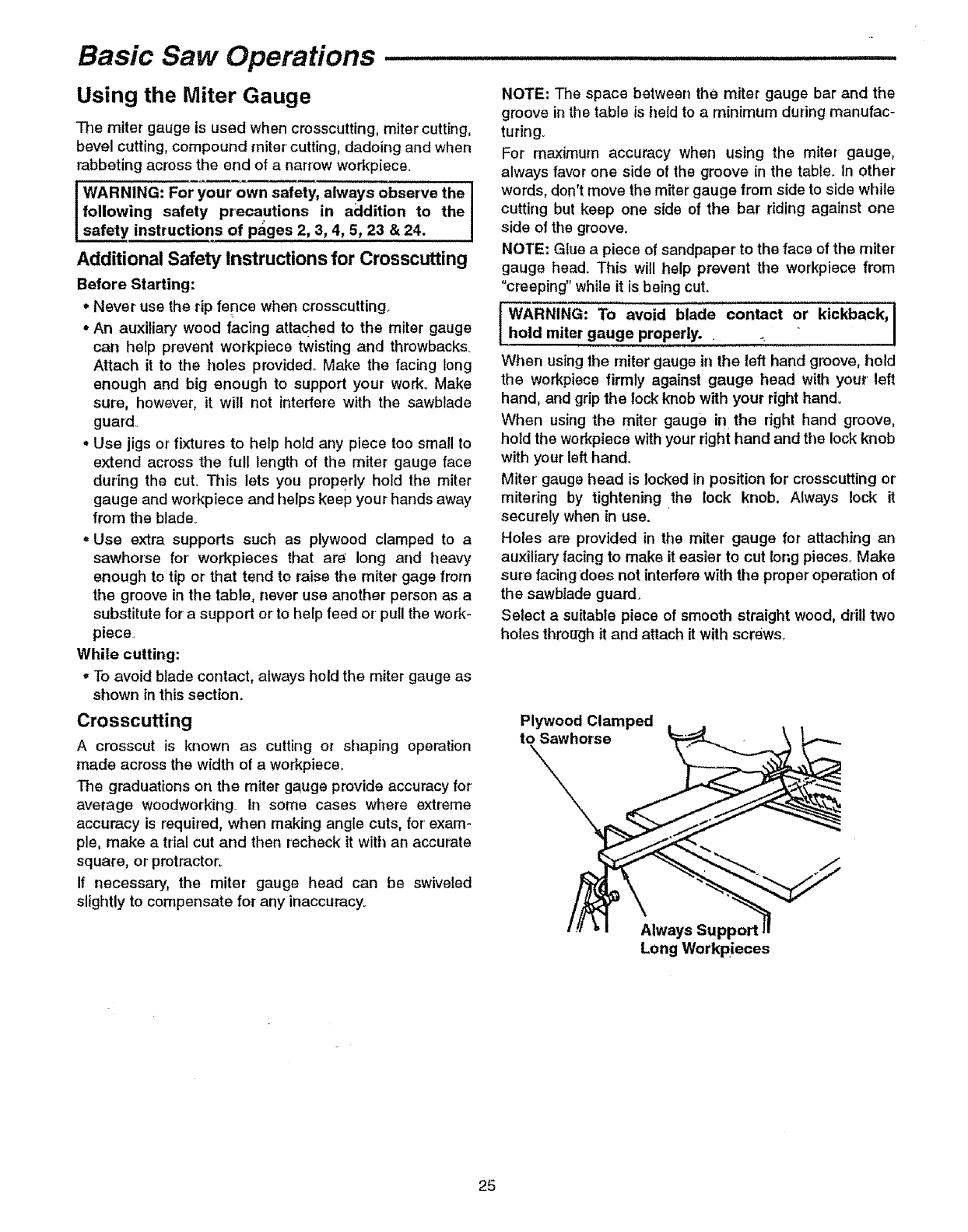
Using the Miter Gauge
The miter gauge is used when crosscutting, miter cutting,
bevel cutting, compound miter cutting, dadoing and when
rabbeting across the end of a narrow workpiece.
IWARNING: For your own safety, always observe the
following safety precautions in addition to the
safety instructions of pages 2, 3, 4, 5, 23 & 24.
Additional Safety Instructions for Crosscutting
Before Starting:
Never use the rip fence when crosscutting..
•An auxiliary wood facing attached to the miter gauge
can hetp prevent workpiece twisting and throwbacks.
Attach it to the holes provided. Make the facing long
enough and big enough to support your work. Make
sure, however, it will not interfere with the sawblade
guard.
° Use jigs or fixtures to hetp hold arty piece too small to
extend across the full length of the miter gauge face
during the cut. This lets you proPerly hold the miter
gauge and workpiece and helps keep your hands away
from the blade.
• Use extra supports such as plywood clamped to a
sawhorse for workpieces that ar_ long and heavy
enough to tip or that tend to raise the miter gage from
the groove in the table, never use another person as a
substitute for a support or to help feed or' pull the work-
piece.
While cutting:
• To avoid blade contact, always hold the miter gauge as
shown in this section.
Crosscutting
Acrosscut is known as cutting or shaping operation
made across the width of aworkpieceo
The graduations on the miter gauge provide accuracy for
average woodworking In some cases where extreme
accuracy is required, when making angle cuts, for'exam-
ple, make atrial cut and then recheck it with art accurate
square, or protractor.
If necessary, the miter gauge head can be swiveled
slightly to compensate for any inaccuracy.
NOTE: The space between the miter gauge bar and the
groove in the table is held to a minimum during manufac-
turing.
For maximum accuracy when using the miter gauge,
always favor one side of the groove in the table. In other
words, don't move the miter gauge from side to side while
cutting but keep one side of the bar riding against one
side of the groove.
NOTE; Glue apiece of sandpaper to the face of the miter
gauge head. This will help prevent the workpiece from
"creeping" while it is being cut.
WARNING; To avoid blade contact or kickback, I
hold miter gauge properly. •.I
When using the miter gauge in the left hand groove, hold
the workpiece firmly against gauge head with your left
hand, and grip the lock knob with your right hand.
When using the miter gauge in the dght hand groove,
hold the workpiece with your right hand and the lock knob
with your left hand.
Miter' gauge head is locked in position for crosscutting or
mitering by tightening the lock knob, Always lock it
securely when in use.
Holes are provided in the miter gauge for attaching an
auxiliary facing to make it easier to cut long pieces. Make
sure facing does not interfere with the proper operation of
the sawblade guard.
Select a suitable piece of smooth straight wood, drill two
holes through it and attach it with screws,.
Plywood Clamped
to Sawhorse
Always
Long Workpieces
25

-Basic Saw Operations (continued)
Repetitive Crosscutting
Repetitive cutting is known as cutting a quantity of pieces
the same length without having to mark each piece.
• When making repetitive cuts from a long workpiece,
make sure it is supported,
WARNING" Never' use the rip fence as a length stop I
because the cutoff piece could bind between the i
fence and the blade causing a kickback. J
1. When making repetitive cuts, clamp a block of wood 3"
long to the table at desired length to act as a length
stop,,
IWARNING: To avoid kickback from twisting the I
Iworkpiece, when clamping the block, make sure l
Ithat the end of the block is well in front of the saw-
Iblade. Be sure it is clamped securely.
2. Slide the workpiece along the miter gauge until it
touches tire btock.o.hold the workpiece securely
against the miter gauge,
3. Make the cut...tum the saw off_xemove the piece after
the blade has stopped and before cutting the next piece_
Miter Crosscutting
Miter' cutting is an angle cutting operation made across
the width of the workpieceo Follow the same procedure as
you would for crosscutting.
• Adjust the miter gauge to the desired angle, and lock it.
oThe miter gauge may be used in either of the grooves
in the table. Make sure it is locked,
• When using the miter gauge in the left hand groove,
hold the workpiece firmly against the miter gauge head
with your left hand, and grip the lock knob with your
right hand.
oWhen using the miter gauge in the right hand groove,
hold the workpiece with your right hand and the lock
knob with your' left hand.
Bevel Crosscutting
Bevel crosscutting is the same as crosscutting except
that the wood is also cut at an angle.o.other than 90° with
the bottom flat side of the wood.
oAdjust the blade to the desired angle,
•Always use the miter gauge inthe groove to the right of
the blade. It cannot be used in the groove to the left
because the blade guard will intedere. Hold the work-
piece with your right hand and the lock knob with your
left hand
i, .ILl .....
26
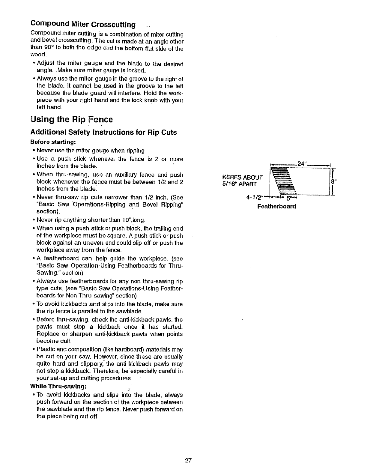
Compound Miter Crosscutting
Compound miter cutting is a combination of miter cutting
and bevel crosscutting,. The cut is made at an angle other
than 90°to both the edge and the bottom flat side of the
wood.
Adjust the miter gauge and tile blade to the desired
angle_,oMake sure miter' gauge is locked.
oAlways use the miter' gauge in the groove to the right of
the blade. It cannot beused in the groove to the left
because the blade guard will interfere.. Hold the work-
piece with your' right hand and tile lock knob with your
left hand
Using the Rip Fence
Additional Safety Instructions for Rip Cuts
Before starting:
• Never use the miter gauge when ripping
• Use a push stick whenever the fence is 2 or more
inches from the blade.
• When thru-sawing, use an auxiliary fence and push
block whenever the fence must be between 1/2 and 2
inches from the blade_
o Never thru-saw rip cuts narrower than 1/2 .inch. (See
"Basic Saw Operations-Ripping and Bevel Ripping"
section).
o Never rip anything shorter than 10'Uong.
oWhen using a push stick or push block, the trailing end
of the workpiece must be square. A push stick or push
block against an uneven end could slip off or push the
workpiece away from the fence,.
=A featherboard can help guide tile workpiece_ (see
"Basic Saw Operation-Using Featherboards for Thru-
Sawing.," section)
° Always use featherboards for' any non thru-sawing rip
type cuts. (see "Basic Saw Operations-Using Feather-
boards for Non Thru-sawing" section)
oTo avoid kickbacks and slips into the blade, make sure
the rip fence is parallel to the sawblade,
° Before thru-sawing, check the anti-kickback pawls., the
pawls must stop a kickback once it has started°
Replace or sharpen anti-kickback pawls when points
become dullo
oPlastic and composition (like hardboard) materials may
be cut on your saw_ However, since these are usually
quite hard and slippery, the anti-kickback pawls may
not stop a kickback. Therefore, be especially careful in
your set-up and cutting procedures.
While Thru-sawing: :,
oTo avoid kickbacks and slips ir_to the blade, always
push forward on the section of the workpiece between
the sawblade and the rip fence,, Never push forward on
the piece being cut off.
i-_--------- 24"-------_
KERFS ABOUT I
5116" APART
Featherboard
27
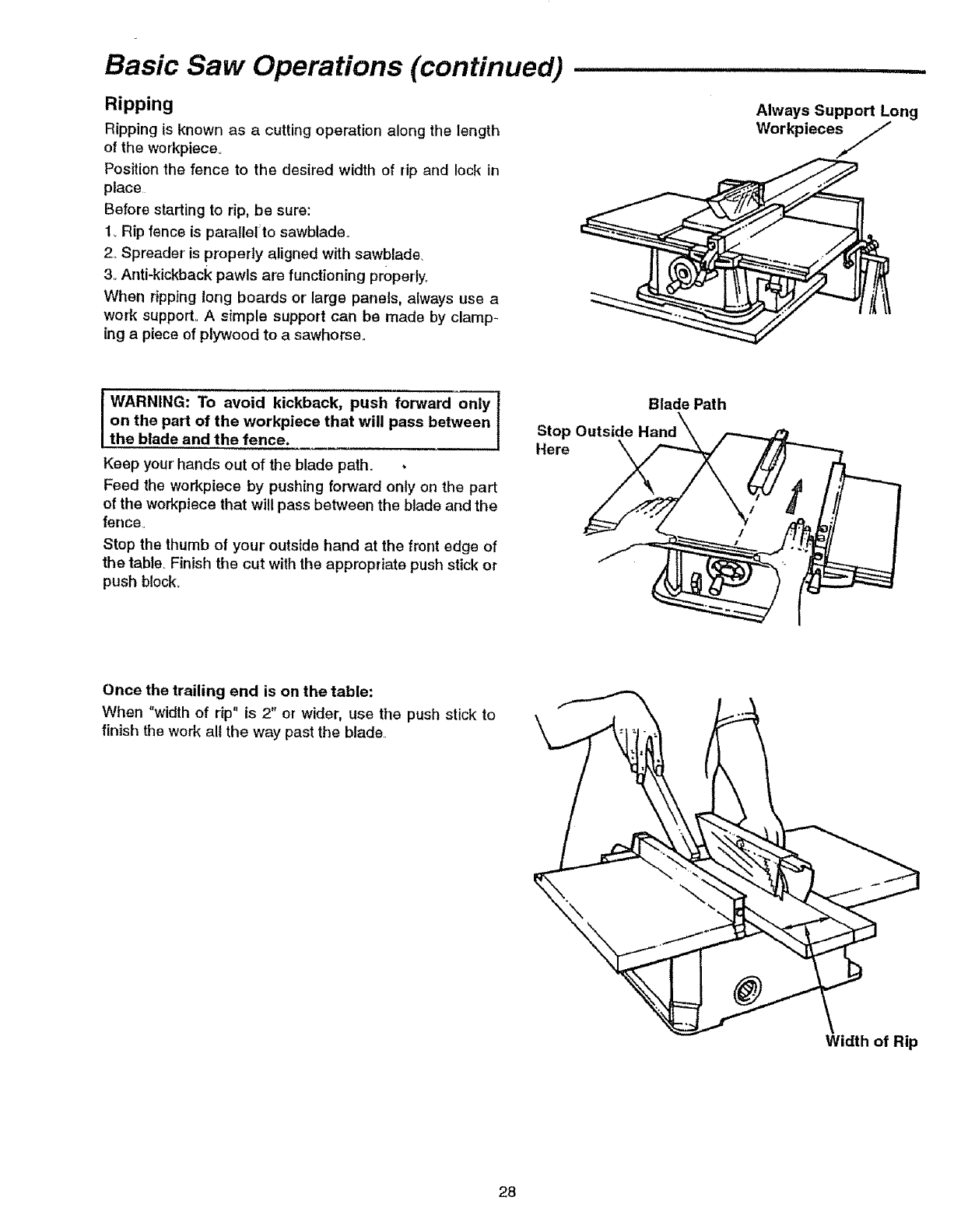
Basic Saw Operations (continued)
Ripping
Ripping is known as a cutting operation along the length
of the workpiece.
Position the fence to the desired width of rip and lock in
place
Before starting to rip, be sure:
1_Rip fence is parallet to sawblade..
2. Spreader' is properly aligned with sawblade.
3oAnti-kickback pawls are functioning properly.
When ripping long boards or' large panels, always use a
work support. A simple support can be made by clamp*
ing a piece of plywood to a sawhorse.,
Always Support Long
Workpiece_,J
kickback, push forward only--]
WARNING: To avoid
on the part of the workpiece that will pass between I
the blade and the fence. /
Keep your hands out of the blade path. •
Feed the workpiece by pushing forward only on the part
of the workpiece that will pass between the blade and the
fence.
Stop the thumb of your' outside hand at the front edge of
the table. Finish the cut with the appropriate push stick or
push block°
Blade Path
Stop Outside
Here \
Once the trailing end is on the table:
When "width of rip" is 2" or wider, use tile push stick to
finish the work all the way past the blade.
Width of Rip
28

When"width ef rip" is narrower than 2", the push stick
cannot be used because the guard wilt interfere° Use the
auxiliary fence and push block for' this ripping operation.
Attach auxiliary fence to rip fence with two "C" clamps_
Auxiliary Work Support/Fence
Feed the workpiece by hand along the auxiliary fence
until the end is approximately 1" past the front edge of the
table° Continue to feed using the push block.
Hold the workpiece in position and install the push block
by sliding it on top of the auxiliary fencelwork support.
This may raise the guard..
Push B
\
IWARNING: To avoid injury from blade contact]
never perform thru-saw cuts narrower than 112"
wide.
Narrow strips thicker than the auxiliary fence/work sup-
port may enter the guard and strike the baffle. Carefully
raise guard only enough to clear the workpiece. Use
push block to complete cut.
Baffl
Bevel Ripping
When bevel ripping material 6" or narrower, use fence on
the right side:of the blade onlyo This_will provide mere
space between the fence and the sawblade for use of a
push stick.. If the fence is mounted to the left, the saw-
blade guard may interfere with proper use of a push stick.
29
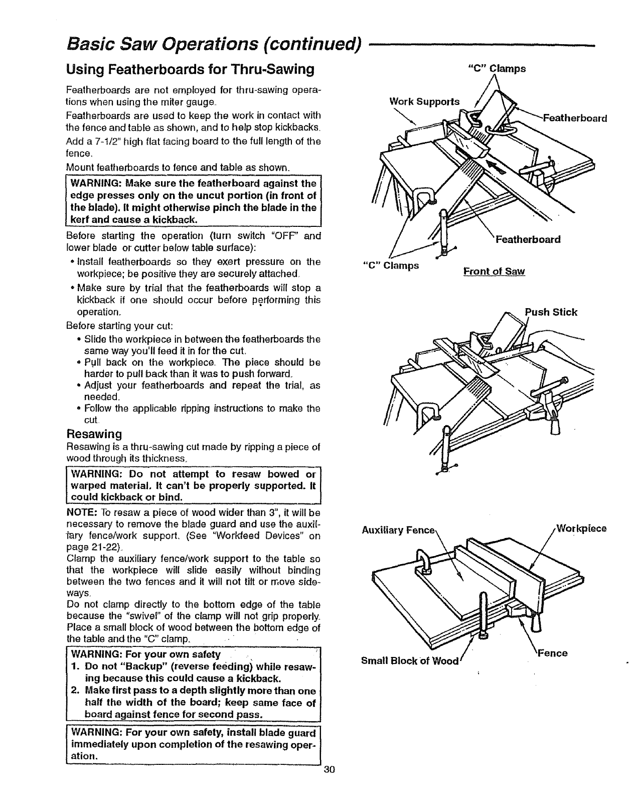
Basic Saw Operations (continued) ............................
Using Featherboards for Thru-Sawing
Featherboards are not employed for thru-sawing opera-
tions when using the miter gauge,
Featherboards are used to keep the work in contact with
the fence and table as shown, and to he!p stop kickbacks_
Add a 7-1/2" high flat facing board to the full length of the
fencer
Mount featherboards to fence and table as shown.
WARNING: Make sure the featherboard against the
edge presses only on the uncut portion (in front of
the blade). It might otherwise pinch the blade in the
kerf and cause a kickback.
Before starting the operation (turn switch "OFF" and
lower blade or cutter below table surface):
• install featherboards so they exert pressure on the
workpiece; be positive they are securely attached.
. Make sure by trial that the featherboards will stop a
kickback if one should occur' before performing this
operation,.
Before starting your cut:
• Slide the workpiece in between the featherboards the
same way you'll feed it in for the cut°
• Pull back on the workpiece. The piece should be
harder to pull back than it was to push forward.
o Adjust your featherboards and repeat the trial, as
needed.
o Fellow the applicable dpping instructions to make the
cut
Resawing
Resawing is a thru-sawing cut made by ripping a piece of
wood through its thickness.
WARNING: Do not attempt to resaw bowed or
warped material, it can't be properly supported. It
could kickback or bind.
NOTE: To resaw a piece of wood wider than 3", it will be
necessary to remove the blade guard and use the auxit-
"i'ary fence/work support_ (See "Workfeed Devices" on
page 21-22)°
Clarnp the auxiliary fence/work support to the table so
that the workpiece wilt slide easily without binding
between the two fences and it will not tilt or' move side-
ways,
Do not clamp directly to the bottom edge of the table
because the "swivel" of the clamp will not grip properly_
Place a small block of wood between the bottom edge of
the table andthe "G" clamp.
WARNING: For your own safety ,
1. Do not "Backup" (reverse feeding) while resaw-
ing because this could cause a kickback.
2. Make first pass to adepth slightly more than one
half the width of the board; keep same face of
board against fence for second pass,
WARNING: For your own safety, install blade guard
immediately upon completion of the resawing oper-
Work Supports
"C" Clamps
Auxiliary Fence_
Small Blockof Wood
30
Featherboard
Front of Saw
"=erboard
Push Stick
\
}iece
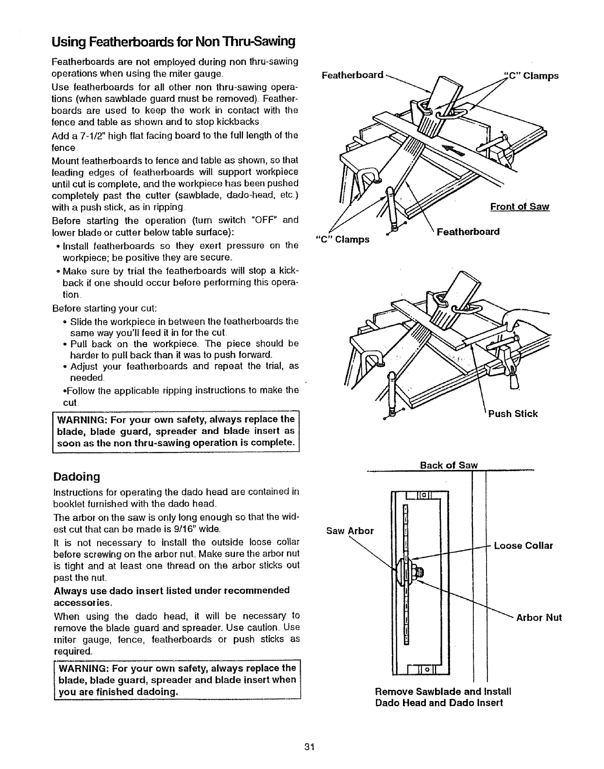
Using Featherboardsfor NonThru-Sawing
Featherboards are not employed during non thru-sawing
operations when using the miter gauge.
Use featherboards for all other non thru-sawing opera-
tions (when sawblade guard must be removed). Feather-
boards are used to keep the work in contact with the
fence and table as shown and to stop kickbacks
Add a 7-I/2" high flat facing board to the full length of the
fence
Mount featherboards to fence and table as shown, so that
leading edges of featherboards will support workpiece
until cut is complete, and the workpiece has been pushed
completely past the cutter (sawblade, dado-head, etc)
with a push stick, as in ripping
Before starting the operation (turn switch "OFF" and
lower blade or cutter below table surface):
• Install featherboards so they exert pressure on the
workpiece; be positive they are secure.
° Make sure by trial the featherboards will stop a kick-
back if one should occur before performing this opera-
tion
Before slarting your cut:
- Slide the workpiece in between the featherboards the
same way you'll feed it in for the cut
-Pull back on the workpiece. The piece should be
harder to pull back than it was to push forward._
-Adjust your featherboards and repeat the trial, as
needed
=Follow the applicable ripping instructions to make the
cut
WARNING: For your own safety, always replace the
blade, blade guard, spreader and blade insert as
soon as the non thru-sawing operation is complete.
Dadoing
Instructions for operating the dado head are contained in
booklet furnished with the dado head..
The arbor on the saw is only long enough so that the wid-
est cut that can be made is 9/16" wide.
It is not necessary to install the outside loose collar
before screwing on the arbor nut° Make sure the arbor nut
is tight and at least one thread on the arbor sticks out
past the nut.
Always use dado insert listed under recommended
accessories.
When using the dado head, it wilt be necessary to
remove the blade guard and spreader. Use caution. Use
miter gauge, fence, featherboards or push sticks as
required..
I WARNING: For your own safety, always replace the !
m
blade, blade guard, spreader and blade insert when 1
you are finished dadoing.
Fea ps
--Fr°°'°'saw
,_ \Featherboard
"C" Clamps
Push Stick
Back of Saw
Saw Arbor
- Loose Collar
Nut
Remove Sawblade and Install
Dado Head and Dado Insert
31
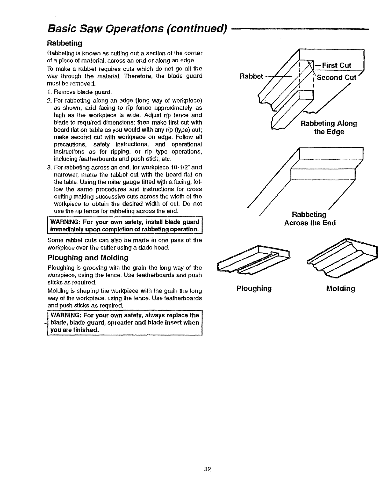
Basic Saw Operations (continued)
Rabbeting
Rabbeting is known as cutting out a section of the corner
of a piece of material, across an end or along an edge_
To make a rabbet requires cuts which do not go all the
way through the material.. Therefore, the blade guard
must be removed
1..Remove blade guard.
2. For rabbeting along an edge (long way of workpiece)
as shown, add facing to rip fence approximately a,s
high as the workpiece is wide. Adjust rip fence and
blade to required dimensions; then make first cut with
board flat on table as you would with any rip (type) cut;
make second cut with workpiece on edge. Follow all
precautions, safety instructions, and operational
instructions as for ripping, or rip type operations,
includingfeatherboards and push stick, etc.
3. For rabbeting across an end, for workpiece I0-1/2" and
narrower, make the rabbet cut with the board flat on
the table.. Using the miter gauge fitted w_tha facing, fol-
low tile same procedures and instructions for cross
cutting making successive cuts across tile width of the
workpiece to obtain the desired width of cut. Do not
use the dp fence for rabbeting across the end.
IWARNtNG" For' your own safety, install blade guard
!..immed!a!ely upon completion of rabbeting operation.
Some rabbet cuts can also be made in one pass of the
workpiece over the cutter using a dado head°
Ploughing and Molding
Ploughing is grooving with the grain the long way of the
workpiece, using the fence.. Use featherboards and push
sticks as required.
Molding is shaping the workpiece with the grain the long
way of the workpiece, using the fence. Use featherboards
and push sticks as required.
! WARNING: For your own safety, alwa_
-I blade, blade guard, spreader and blade insert when
[you are finished.
Rabbet
Ploughing
First Cut
Rabbeting Along
the Edge
S
Rabbeting
Across the End
Molding
32

installation and Operation of Mol Head ,,
To get full arbor nut engagement with the arbor ttlreads ....
this saw requires a special molding head mounting
arrangement Always arrange and mount the molding
head as shown. Instructions for assembling and operat-
ing the molding head are contained in a booklet furnished
with the molding head°
Follow molding head installation instructions for table
saws, except use the loose blade collar' supplied with the
saw instead of the spacer washer supplied with the mold-
ing head° Do NOT use the spacer washer provided with
the molding head.. Always position the loose blade collar
as shown.
Always use the molding insert listed under recom-
mended accessories.
When using the molding head it will be necessary to
remove the blade guard and spreader. Use cautien_ Use
miter gauge, fence, featherboards, or push sticks, etc., as
required.
LyWARNING: your own safety, always replace the l
For
blade, blade guard, spreader and blade insert when I
ou are finished molding. I
BackofSaW
Saw Arbor
Loose
Blade
Front of Saw
Molding Head Mounting
g Head
Nut
Maintaining Your Table Saw ..................................
Maintenance
and remove plug from power source outlet
maintaining or lubricating your saw.
oDo not a!low sawdust to accumulate inside the saw
Frequently blow out any dust that may accumulate
inside the saw cabinet and the motor:
oClean your cutting tools with a gum and pitch remover.
°The cord and the tool should be wiped with a dry clean
cloth to prevent deterioration from oil and grease.
°A coat of automobile-type wax applied to the table will
help to keep the surface clean and allow workpieces to
slide more freely.
°If the power cord is worn, cut, or'damaged in any way,
have it replaced immediately_
IMPORTANT: Certain cleaning agents and solvents can
damage plastic parts.. Some of these are: gasoline, car-
bon tetmch!oride, chlorinated cleaning solvents, ammo-
nia and household detergents which contain ammonia_
Avoiding use of these and other types of cleaning agents
will minimize the possibility of damage. Use cleaners suit-
able for prescription glasses or liquid dishwashing deter'-
gent and water.
Anti-Kickback Pawls
Make sure the teeth of tile anti-kickback pawls are always
sharp. To sharpen:
1. Remove blade guard..
2_Rotate pawl toward rear of spreader so that teeth are
above top of spreader:
3..Hold spreader with left hand and place pawl over cor-
ner of workbench as shown.
4..Using a small round file, (smooth cut) sharpen the
teeth.
5 Reinstall blade guard
Anti-Kickback
Pawl
WARNING: All repairs, electrical or mechanical,]
should be attempted only by a trained repairman. |
Contact the nearest Sears store for service. Use I
only identical replacement parts. Any other parts |
may create a hazard. |
33
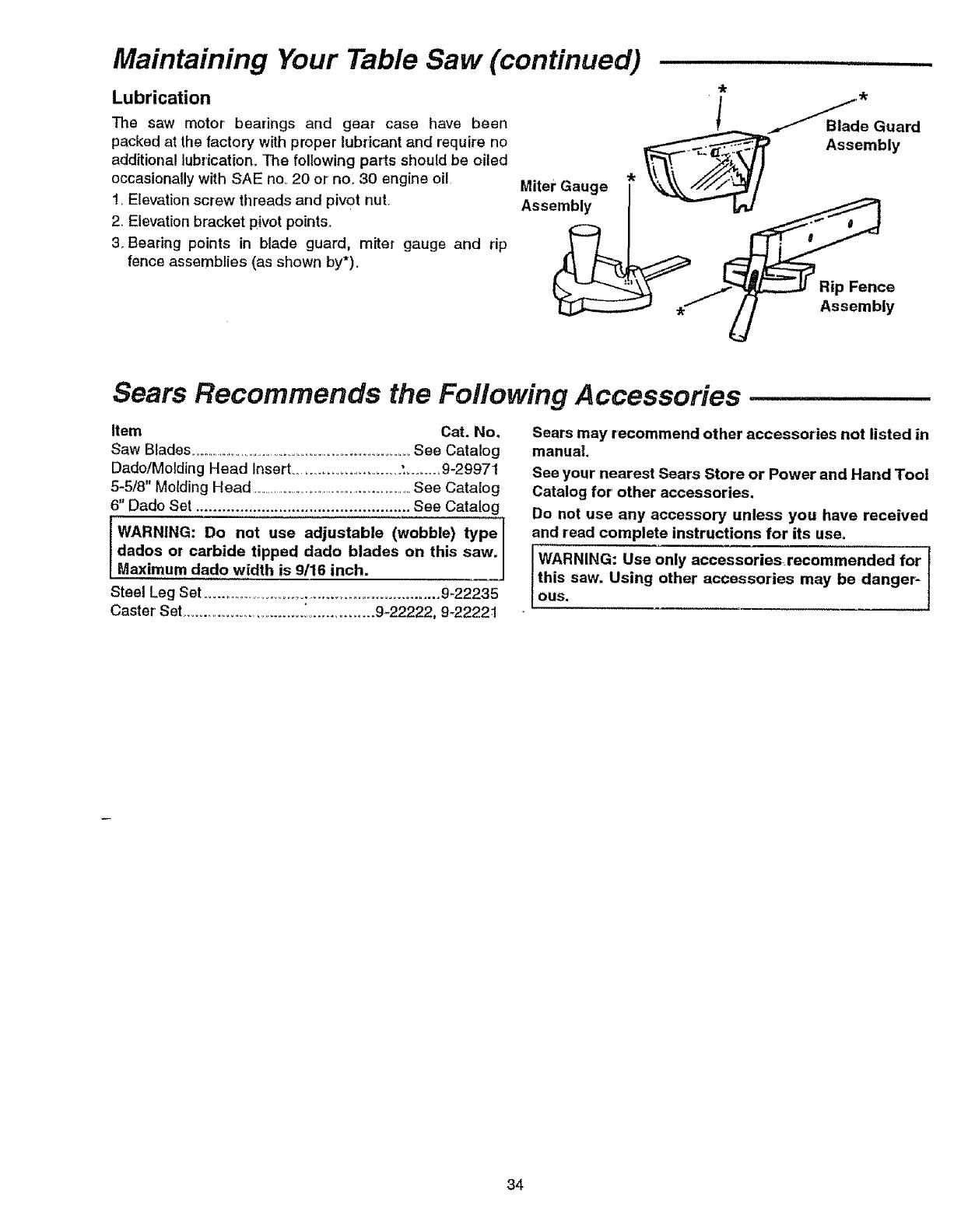
Maintaining Your Table Saw (continued)
Lubrication
The saw motor bearings and gear case have been
packed at the factory with proper lubricant and require no
additional lubrication_ The following parts should be oiled
occasionally with SAE no. 20 or' no. 30 engine oil,
lrElevation screw threads and pivot nuL
2_Elevation bracket pivot points,,
3. Bearing points in blade guard, miter gauge and rip
fence assemblies (as shown by*)=
Miter Gauge _ _ Assembly
Ass_ vI,-d
Assembly
Sears Recommends the Following Accessories
Item Cat. No.
Saw Blades ...................................................................See Catalog
DadoiMolding Head Insert ........................... ',........ 9-29971
5-5/8" Molding Head ...........................................................See Catalog
6" Dado Set ................................................. See Catalog
WARNING: Do not use adjustable (wobble) type
dados or carbide tipped dado blades on this saw.
Maximum dado width is 9116 inch.
Steel Leg Set ...............................................................9_22235
Caster' Set .............................. i............... 9-22222, 9-22221
Sears may recommend other accessories not listed in
manual.
See your nearest Sears Store or Power and Hand Tool
Catalog for other accessories.
Do not use any accessory unless you have received
and read complete instructions for its use.
IWARNING: Use only accessories_recommended for J
this saw. Using other accessories may be danger `=
OUS.
34
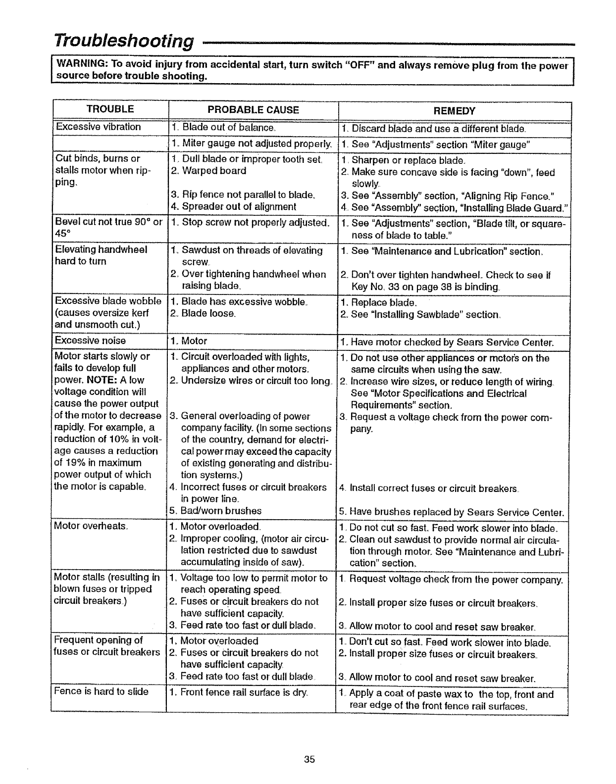
Troubleshooting ...................
WARNING: To avoid injury from accidental start, turn switch "OFF" and always remove plug from the power']
source before trouble shooting. t
TROUBLE PROBABLE CAUSE REMEDY
Excessive vibration 1. Blade out of balancer. 1Discard blade and use a different blade,
1_Miter gauge not adjusted properly° 1. See "Adjustments" section "Miter gauge"
Cut binds, burns or 1. Dull blade or' improper tooth set. 1. Sharpen or replace blade.
stalls motor when rip- 2o Warped board 2. Make sure concave side is facing "down",feed
ping. slowty.
3. Rip fence not parallel to blade.. 3. See =Assembly" section, "Aligning Rip Fence."
4o Spreader out of alignment 4. See "Assembly" section, "Installing Blade Guard°"
Bevel cut not true 90 °or 1oStop screw not properly adjusted. 1. See "Adjustments" section, "Blade tilt, or square-
45 °ness of blade to table."
Elevating handwheel 1oSawdust on threads of elevating 1_See "Maintenance and Lubrication" section_
hard to turn screw
2. Over tightening handwheel when 2. Don't over tighten handwheel.. Check to see if
raising blade.. Key No_33 on page 38 is binding
1, Blade has excessive wobble° 1. Replace blade.
2. Blade loose. 2. See "Installing Sawblade" section..
1.
1.
Excessive blade wobble
(causes oversize kerr
and unsmooth cut.)
Excessive noise
Motor' starts slowly or
fails to develop full
power_ NOTE: A low
voltage condition will
cause the power output
of the motor to decrease
rapidly_ For example, a
reduction of 10% in volt-
age causes a reduction
of 19% in maximum
power output of which
the motor is capable_
Motor' ovedleats.
Motor stalls (resulting in
blown fuses or tripped
circuit breakers.)
Frequent opening of
fuses or circuit breakers
Fence is hard to slide
2_
Motor
Circuit overloaded with lights,
appliances and other motors..
Undersize wires or circuit too long..
3_General overloading of power
company facility. (In some sections
of the country, demand for electri-
cal power may exceed the capacity
of existing generating and distribu-
tion systems..)
4. Incorrect fuses or circuit breakers
in power line..
5oBad/worn brushes
1. Motor' overloaded.
2_ Improper' cooling, (motor air circu-
lation restricted due to sawdust
accumulating inside of saw).
1_Voltage too low to permit motor to
reach operating speed
2. Fuses or circuit breakers do not
have sufficient capacity.
3_ Feed rate too fast or dull blade_
1. Motor overloaded
2_ Fuses or Circuit breakers do not
have sufficient capacity
3. Feed rate too fast or dull blade
1,.Front fence rail surface is dry_
1. Have motor ctlecked by Sears Service Center_
1. Do not use other' appliances or rectors on the
same circuits when using the saw..
2. Increase wire sizes, or reduce length of wiring
See "Motor' Specifications and Electrical
Requirements" section.
3_ Request a voltage check from the power com-
pany.
4 Install correct fuses or circuit breakers
5_Have brushes replaced by Sears Service Center:
1, Do not cut so fast,, Feed work slower into blade_
2. Clean out sawdust to provide normal air circula-
tion through motor. See "Maintenance and Lubri-
cation"section_
1, Request voltage check from the power company_
2_ Installproper size fuses or circuit breakers_
3,,Allow motor to cool and reset saw breaker°
1,,Don't cut so fast.. Feed work slower into blade,,
2. Install proper size fuses or' circuit breakers,
3..Allow rnotor to cool and reset saw breaker,
1,,Apply a coat of paste wax to the top, front and
rear edge of the front fence rail surfaces,.
35

Repair Parts .......
Parts List for Craftsman 10" Bench Top Table Saw
Model No. 113.221740
Figure 1
I
40
37
36
38 !
I
I
d
1314 15 16
24
28 27 26
22 21
20 19
36

Repair Parts .... ......
Parts List for Craftsman!i(Y' B ¢h Top Tabie
Model No:l 13.221740
Always Order by Pa_ Number:- Not KeyNumber
Figure I
_i ¸¸.
Key
Noo
1
2
3
4
5
6
7
8
9
10
11
12
13
14
15
16
17
18
19
20
21
22
Part No
817357 i
822497
822498
822487-1
823170
823023
823022
823046
STD852004
56-100002
823047
823167
STD551025
Description
Screw, Ty "E" M4 x 16-12
Insert, Table
Nut, Speed M4 x 16
Screw, Cr-Special
Table
Scale R_H.
Scale L.H_
Clamp, Plate
* Lockwasher, ExL M4
Nut, Hex M4 x .7
Screw, Cr Flat Hd M3 x ..5-7
Label, Trim Panel
* Washer, 17/64 x 5/8 x 1/32
60545
823042
823041
823044
823043
823086
823085
STD541031 *
823052
Washer, Nylon
Nut, Locking
Knob, Bevel Lock
Spring, Compression
Bolt, Special
Screw Fillister Head
Knob
Nut, Hex 5/16_18
Handwheel, Elevation
Key
No.
23
24
25
26
27
28
29
3O
31
32
33
34
35
36
37
38
39
40
41
42
Part No. Description
813249-132
823053
823050
9=22255
822308
STD611007
823010
STD610807
823012
823048
823094
823049
823172
823024
46-57680-3
822493
822487
823001
820816
820815
SP5754
Pin, Roll
Rod, Screw
_Reset Switch, w/nut
1"Key, Locking
Switch, Locking
* Screw, Ty nAB" #10 x 3/4
Clamp, Cord
* Screw, Pan Hd #8 x 3/4
Box, Switch
Cord w/plug
Grommet
Foot, Rubber
Base
Outlet, Dust
* Screw, M4 x o7-16
Screw, Hex Serf. Flat Hd
Screw, Cr-Special
Screw, Cr-Special
Wrench, Shaft ¢_f_
Wrench, Arbor Nut
Owners Manual 0"_otIllus-
trated)
* Stanard Hardware Item - May be purchased locally
1"Stock Item - May be secure through the hardware department of most Sears retail steres.
WARNING: Service of double-insulated parts, in a double-insulated tool, two systems of insulation are pro*
vided instead of grounding. No grounding means is provided on a double-insulated tool nor should a means
i for grounding be added. Servicing a double insulated took requires extreme care and knowledge of the sys-
tem, and should be done by a qualified service personnel. Replacement parts for a double-insulated tool
must be identical to the parts they replace. Your doubl_.insutated tool is marked with the works "DOUBLE-
INSULATED" and the _-] (square within a square).
37
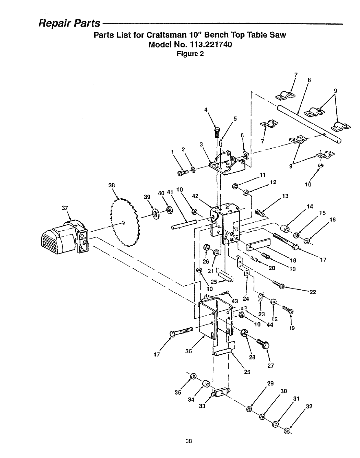
Repair Parts ..................................................................
Parts List for Craftsman 10" Bench Top Table Saw
Model No. 113.221740
Figure 2
37
38
39
14
15 16
43 24
19
17
22
17
35 /
34 ,,/
33
I
I
28
25
19
27
29
30
31
32
38

Repair Parts ....................................................... .........................'"
Parts List for Craftsman 10" Bench Top Table Saw
Model No. 113.221740
Always Order by Part Number - Not Key Number
Figure 2
I
Key
No.
1
2
3
4
5
6
7
8
9
10
1t
12
13
14
15
16
17
18
19
2O
21
22
Part No Description
821151-3
STD852005
823035
823105
819249-104
823037
823000
823034
822499
822488
STD541010
STD551210
822489-1
i802392-49
iSTD541025
iSTD551025
!STD522532
823031
STD511003
823015
STD551131
805517
Screw, Hex Hd. M5 x .8-20
* Lockwasher; Exto M5
' Bracket, Pivot Rod
Screw, Serf Hd. 1/4-20 x 3/4
Pin, Roll 4 x 16
Spacer
Clamp, Rod Pivot Rear
Rod, Pivot
Clamp, Rod Pivot
Nut, Hex 1/4-20
Nut, Hex 10-24
Lockwasher; Ext. #10
Bolt, Caniage 1/4-20 x 1-1/4
Spacer
Nut, Hex 1/4-20
Washer, 17/64 x 5/8 x 1132
* Screw, Hex Hd. t14-20_x3-1/4
Plate, Deflector
* Screw, Pan Hd. 10-24 x 3/8
Spring, Compression
* Lockwasher, Ext. 5/16
Screw, Pan Hd. 5/16-18 x 1/2
Key
No
23
24
25
26
27
28
29
30
31
32
33
34
35
36
37
38
39
4O
41
42
43
44
Part No.
823007
823005
82303O
STD54t031
STD833016
ISTD852006
!823018
823018-1
823019
808447-7
823017
823O16
820632-1
823028
823O26
9-32556
60547
820818
821733-290
823036
823029
823997
Description
Indicator', Blade Tilt
Bracket, Indicator Support
Spacer, 9.5 x 685
Nut Hex 5/16-18
Screw, Hex Hdo M6 x 1-18
Lockwasher, M6
Nut, Hex Special 3/8-16 x 5/32
Nut, Hex Special 3/8-16 x 13/64
Washer, Fiber 10mm
Washer; Wave 10ram
Bar, Rocker
Spacer 6.2 ×16 x 3_1
Ring, Retaining
Bracket, Motor
Motor' (see Fig° 5)
Blade, 10" Chisef'Tooth
Collar Blade
Nut, Saw Arbor
Pin, Roll 8 x 90
Plate, Mounting
Screw, Cr:. Pan Hd Shoulder
Screw Pan Hd. Shoulder
5
6
Figure 3
Key
No.
'1"
2
3
4
5
6
7
8
Part No_ Description
............ t
823065
60545
823O68
823069
STD510802
823066
823198
823157
Knob Miter Gauge
Washer, Nylon
Pad, Sliding
Screw, Rat Cr_ Hd..Ty "TT"
M4 x .,7x 8
*Screw #8-32 x 1/4
Indicator, Miter Gauge
Bar, Miter Gauge
Body, Miter Gauge
* Standard Hardware Item - May be Purchased Locally
t Stock Item - May be secm'ed through the hardware department of most Sears Retail Stores
• 39
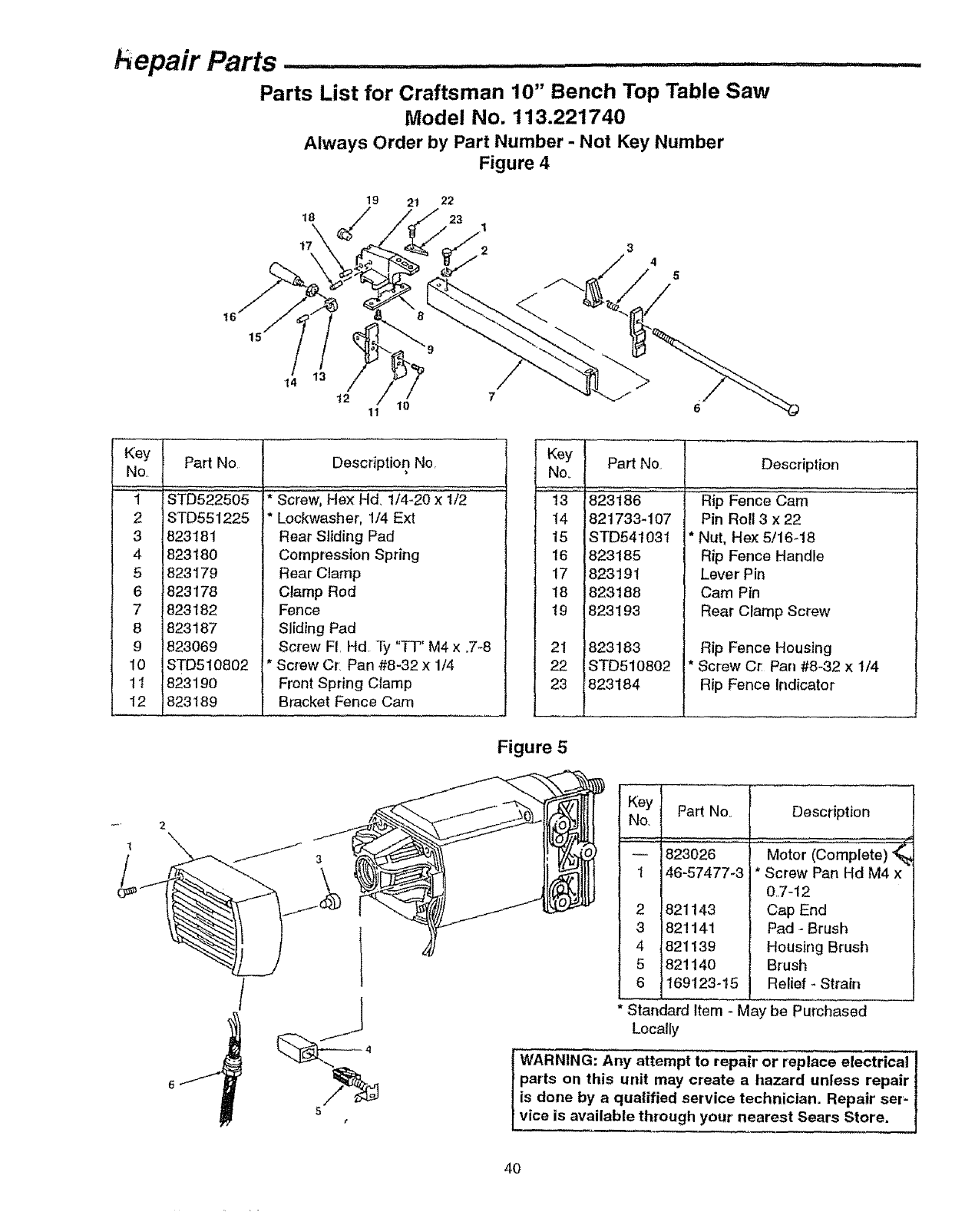
,Tu,, ..i,l,ii ¸
L. .. Parts ,,,..................................................................
Parts List for Craftsman 10" Bench Top Table Saw
Model No. 113.221740
Always Order by Part Number -Not Key Number
Figure 4
18\
17
19 21 22
23
34
14 13
t2 10 6
11
Part No, Description
Kev l Part No
No, J
2_
3t
41
51
61
8 1823187
9823069
10 STD510802
1t i82a19o
12 1823189
STD522505
STD551225
823181
82318O
823179
823178
823182
Description No,
Screw, He)( Hd. 1/4-20 x 1/2
Lockwasher, 1/4 Ext
Rear Sliding Pad
Compression Spring
Rear Clamp
Clamp Rod
Fence
Sliding Pad
Screw F[ Hd Ty "TT" M4 x °7-8
Screw Cr. Pan #8-32 x 1/4
Front Spring Clamp
Bracket Fence Cam
Key
No.
13
14
15
16
17
18
19
:
21
22 !
23
Figure 5
823186
821733-107
STD541031
823185
823191
823188
823193
823183
STD510802
823184
Rip Fence Cam
Pin Roll 3x 22
*Nut, He;< 5/16-18
Rip Fence Handle
Lever Pin
Cam Pin
Rear Clamp Screw
Rip Fence Housing
*Screw Cr, Pan #8-32 x 1/4
Rip Fence Indicator
1
I Key Par1 Nor Description
No,
....'i _ 823026
46-57477-3
* Standard ltem - May be Purchased
Locally
821143
821141
821139
82114O
169123-15
Motor (Complete)
Screw Pan Hd M4 x
0,.7-12
Cap End
Pad -Brush
Housing Brush
Brush
Relief - Strain
WARNING: Any attempt to repair' or replace electrical
parts on this unit may create a hazard unless repair
is done by a qualified service technician. Repair ser'-
vice is available through your nearest Sears Store.
40
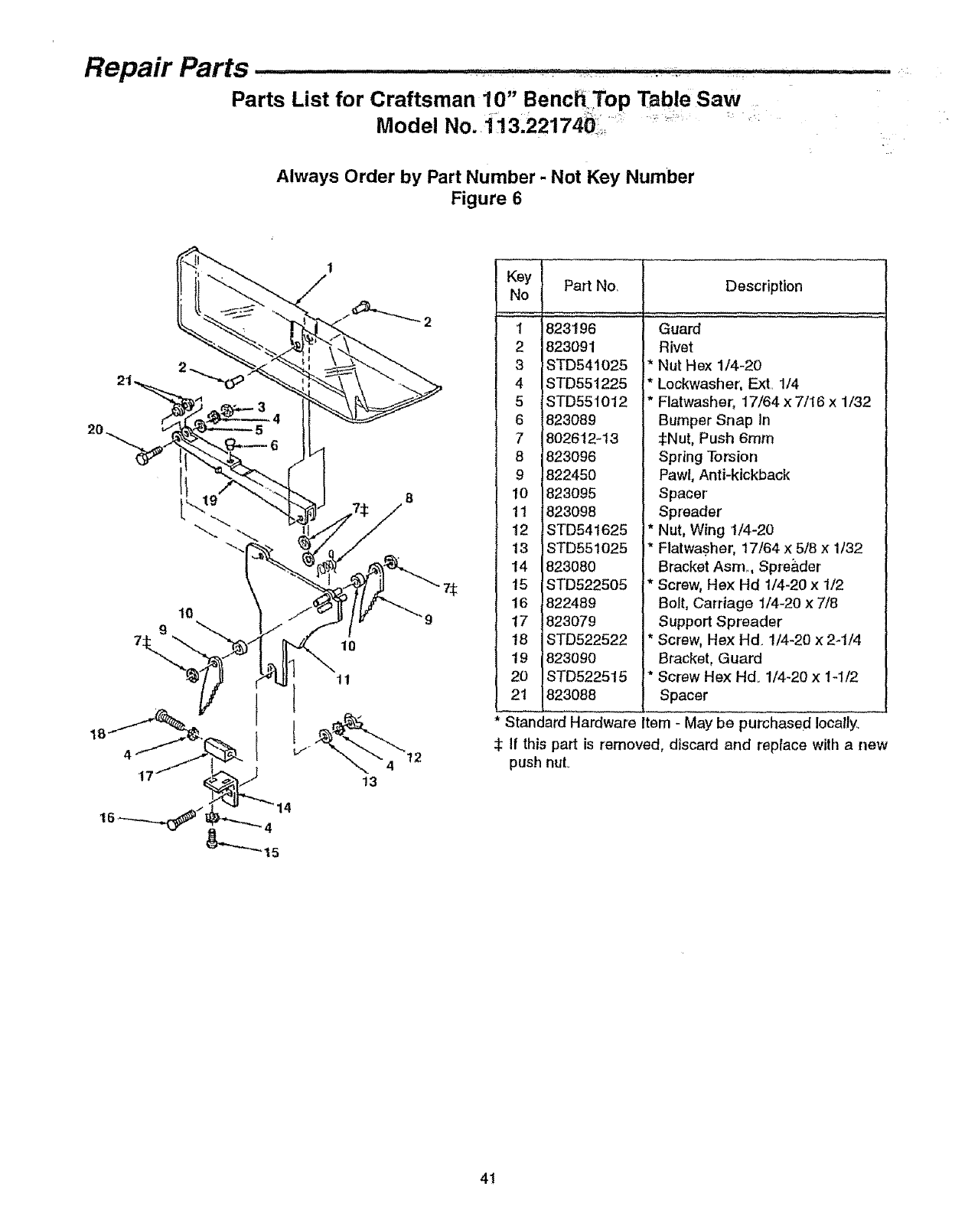
Repair Parts .... ................, .
Parts List for Craftsman 10" BenchTop Table Saw
Model No. 3.22174_ii, '_ _'_ _`
Always Order by Part Number -Not Key Number
Figure 6
t
171
9
10
11
13
75
Key
No
,,;;; , ,
I
2
3
4
5
6
7
8
9
10
11
12
13
14
15
18
17
18
19
20
Part No.
823196
823091
STD541025
STD551225
STD551012
823089
8026t2-13
823096
822450
823095
823098
!STD541625
STD551025
823080
STD522505
822489
823079
STD522522
823090
STD522515
Description
Guard
Rivet
* Nut Hex 114-20
* Lockwasher, Ext 114
*Flatwasher, 17/64 x 7/16 x 1/32
Bumper Snap In
:_Nut, Push 6ram
Spring Torsion
Pawl, Anti-kickback
Spacer
Spreader
* Nut, Wing t/4-20
* Flatwasher, 17164 x 5/8 x 1/32
Bracket Asm., Spre_.der
* Screw, Hex Hd 1/4-20 x 1/2
Bolt, Carriage 1/4-20 x 7/8
Support Spreader
Screw, Hex Hd 1/4-20 x 2-t/4
Bracket, Guard
Screw He)( Hd. 1/4-20 x 1-1/2
21 823088 Spacer
S-_andard Hardware Item - May be purchased Iocally_
If this part is removed, discard and replace with a new
push nuL
41

f
8WAIRS
owner's
rnanual
MODEL NO.
113.221740
The model number of your table
saw is found at the rear' of the
base,_
When requesting service or'
ordering parts, always provide
the following information:
• Product Type
-Model Number
•Part Number
•Part Description
p,-_L ,,,,HIIHI
10 INCH BENCH TOP
TABLE SAW
For the repair or replacement paris youneed
Call 7 am - 7 pro,7 days a week
1 =800-366-PART
(1-800-366-7278)
For in-homemajor brandrepair service
Call 24 hoursa day, 7 daysa week
1-800-4=RIPAHR
(1,-8g0-473-7247)
Forthe location of a
Sears RepairServiceCenter in your area
Call 24 hours aday, 7 days a week
1-8OO-488= 1222
For informationonpurchasinga Sears
Maintenance Agreementor to inquire
about an existingAgreement
Call 9 arn - 5 pro,Monday-Saturday
1-8OO-827-6655
America's Repair SpeciatL_t5
Part No,, 8P5754
J _.= ...................
Sears, Roebuck and Co., Hoffman Estates, IL, 60179 U.S.A.
Form No.. SP5754-3 Printed in U.S.Ao
,)
