Craftsman 11323112 User Manual 10 INCH RADIAL SAW Manuals And Guides L0805252
CRAFTSMAN Saw Radial Manual L0805252 CRAFTSMAN Saw Radial Owner's Manual, CRAFTSMAN Saw Radial installation guides
User Manual: Craftsman 11323112 11323112 CRAFTSMAN 10-INCH RADIAL SAW - Manuals and Guides View the owners manual for your CRAFTSMAN 10-INCH RADIAL SAW #11323112. Home:Tool Parts:Craftsman Parts:Craftsman 10-INCH RADIAL SAW Manual
Open the PDF directly: View PDF ![]() .
.
Page Count: 36
ISears i
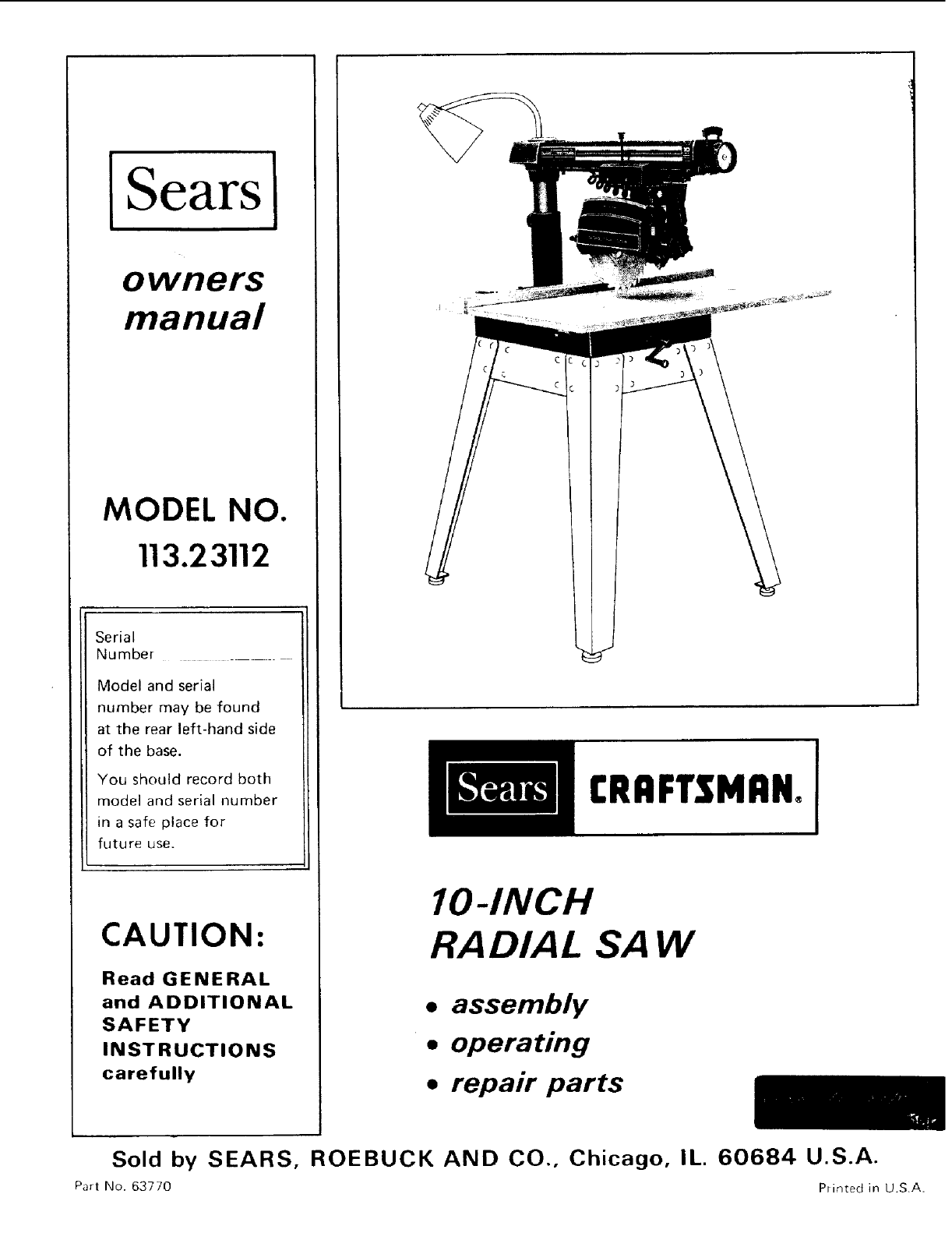
owners
manual
MODEL NO.
113.23112
Serial
Number
Model and serial
number may be found
at the rear left-hand side
of the base.
You should record both
model and serial number
in a safe place for
future use.
CAUTION:
Read GENERAL
and ADDITIONAL
SAFETY
INSTRUCTIONS
carefully
[RRFTSMRN°
IO-INCH
RADIAL SAW
• assembly
•operating
•repair parts
Sold by SEARS, ROEBUCK AND CO., Chicago, IL. 60684 U.S.A.
Part No. 63770 Printed in U.SA.
FULL ONE YEAR WARRANTY ON CRAFTSMAN RADIAL SAWS
If within one year from the date of purchase, this Craftsman Radial Saw fails due to a defect in material or
workmanship, Sears will repair it, free of charge.
Warranty service is available by simply contacting the nearest Sears store or Service Center throughout the
United States.
This warranty gives you specific legal rights, and you may also have other rights which vary from state to
state. SEARS, ROEBUCK AND CO.
BSC 41-3
SEARS TOWER
CHICAGO, IL 60684
general safety instructions for power tools
1. KNOW YOUR POWER TOOL
Read the owner's manual carefully. Learn its
application _nd limitations as well as the specific
potential hazards peculiar to this tool.
2. GROUND ALL TOOLS
Fhs tool rs equipped with an approved 3conductor
cord and a 3-p_ong grounding type plug to fit the
proper grounding type receptacle. The green conductor 15.
in the cord _s the grounding wire. Never connect the
green wire to a live terminal.
3. KEEP GUARDS IN PLACE
irl working order, and in proper adjustment and
alignment.
4. REMOVE ADJUSTING KEYS
AND WRENCHES
Fo_m habit )f checking to see that keys and adjusting
wrenches ar_ removed from tool before turning _t on.
5. KEEP WORK AREA CLEAN
Cluttered areas and benches _nvite acodents Floor
must not be shppery due [o wax o_ sawdust
6. AVOID DANGEROUS ENVIRONMENT
Don't use power tools in damp or wet locations or
expose them to rain. Keep work area well lighted.
Provide adequate surrounding work space.
7. KEEP CHILDREN AWAY
Ali visitors should be kept a safe distance from work
af ea
8. MAKE WORKSHOP KID-PROOF
with padlocks, master sw_tches, or by removing
starte_ keys. 20.
9. DON'T FORCE TOOL
It ,,,:ill do th-' job better and safe_ at the rate Ior whch
pt was design, d.
10. USE RIGHT TOOL
Don't force tool or attachment [o do a job _t was not
designed for
11. WEAR PROPER APPAREL
Do not wear loose clothing, gloves, neckties or jewelry
0ings, wrist watches) to get caught in mowog parts.
Nonslip footwear is recommended. Wear protective
hair covering to contain long hai_. Roll long sleeves
above the elbow
12. USE SAFETY GOGGLES (Head Protection} 22.
Wear Safety goggles (must comply with ANS Z87.1) at
all t_mes. Also, use face or dust mask if cutting
operation is dusty, and ear protectors (p]ugsor muffs)
during extended periods of operation.
13. SECURE WORK
Use clamps or a vise to hold work when practical It's
safe_ than using your hand, frees both hands to operate
tool.
14. DON'T OVERREACH
Keep proper footing and balance at all times.
MAINTAIN TOOLS WITH CARE
Keep tools sharp and clean for best and safest
performance Follow instructions for lubricating and
changing accessories
16. DISCONNECT TOOLS
before servicing; when changing accessories such as
blades, bits, cutters, etc.
17. AVOID ACCIDENTAL STARTING
Make sure switch is in "OFF" position before plugging
in.
18. USE RECOMMENDED ACCESSORIES
Consult the owner's manual for recommended
accessories. Follow the instructions that accompany
the accessories. The use of improper accessories may
cause hazards.
19. NEVER STAND ON TOOL
Serious injury could occur if the tool is tipped or if the
cutting [ool is accidentally contacted.
Do not store materials above or near tile tool such that
tt is necessary to stand on the tool to reach them.
CHECK DAMAGED PARTS
Before further use of the toot, a guard or other part that
J_ damaged should be carefully checked to ensure that t
will operate properiy and perform its ntended function.
Check for alignment of moving parts, binding of mowng
parts, breakage of parts, mounting, and any other
conditions that may affect its operation. A guard or
other part that is damaged should be properly' repaired
or replaced.
21, DIRECTION OF FEED
Feed work into a blade or cutter against the direction
of rotation of the blade or cutter only
NEVER LEAVE TOOL RUNNING
UNATTENDED
Turn power off. Don't leave tool until if comes to a
complete stop.
additional safety instructions for radial saws
CAUTION: Always disconnect the power cord before
removing the guard, changing the cutting tool, changing the
set-up or making adjustments. Shut off motor before
performing layout work on the saw table.
WARNING: DO NOT CONNECT POWER CORD UNTIL
THE FOLLOWING STEPS HAVE BEEN
SATISFACTORI LY COMPLETED:
I. Assembly and alignment.
II. Examination and operating familiarity with ON-OFF
switch, elevation control, yoke index and lock, bevel
index and lock, carriage lock, guard clamp screw,
spreader and anti-kickback device, and miter index and
lock.
I11. Review and understarlding of all Safety Instructions and
Operating Procedures thru-out manual.
INSTALLATION
f. St_Lcarriage lock before moving the saw.
2. Bolt the saw to the floor if it tends to slip, walk, or
shale during normal operation.
3. Mount the saw so the table
is approximatel v 39" above the floor;
slopes slightly downward to the rear so the carriage
wilt not roll forward due to gravity.
MINIMIZE ACCIDENT POTENTIAL
Most accidents are caused by FAILURE TO FOLLOW
setup and operating instructions:
(A) GENERAL
- Avoid awkward hand positions, where a sudden slip
could cause a hand to move into a sawblade or other
cutting tool. Never reach in back of or around the
cutting tool with either hand to hold down the
workpiece, or for any other reason; DO NOT place
fingers or hands in the path of the sawblade.
-Never saw, dado, mold, or rabbet unless the proper
guard is installed and set up as instructed.
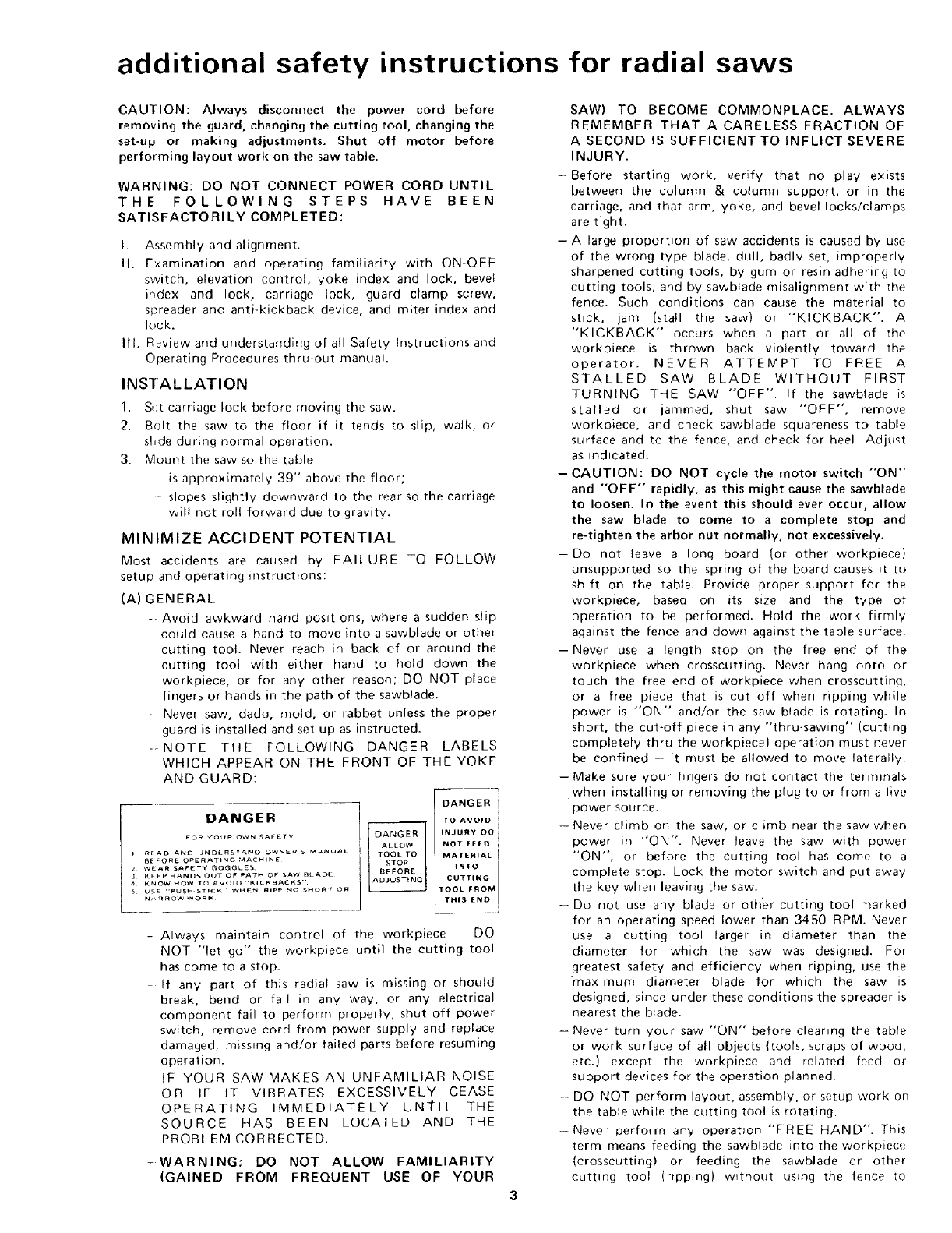
--NOTE THE FOLLOWING DANGER LABELS
WHICH APPEAR ON THE FRONT OF THE YOKE
AND GUARD:
DANGER
TO AVOID
INJURY DO
NOT FEED i
MATERIAL ]
INTO I
CUTTING
: THIS END
TOOL FROM
-Always maintain control of the workpiece -- DO
NOT "let go" the workpiece until the cutting tool
has come to a stop.
If any part of this radial saw is missing or should
break, bend or fail in any way, or any electrical
component fail to perform properly, shut off power
switch, remove cord from power supply and replace
damaged, missing and/or failed parts before resuming
operation.
IF YOUR SAW MAKES AN UNFAMILIAR NOISE
OR IF IT VIBRATES EXCESSIVELY CEASE
OPERATING IMMEDIATELY UNI"IL THE
SOURCE HAS BEEN LOCATED AND THE
PROBLEM CORRECTED.
-WARNING: DO NOT ALLOW FAMILIARITY
(GAINED FROM FREQUENT USE OF YOUR
SAW) TO BECOME COMMONPLACE. ALWAYS
REMEMBER THAT A CARELESS FRACTION OF
A SECOND IS SUFFICIENT TO INFLICT SEVERE
INJURY.
--Before starting work, verify that no play exists
between the column & column support, or in the
carriage, and that arm, yoke, and bevel locks/clamps
are tight.
-A large proportion of saw accidents is caused by use
of the wrong type blade, dull, badly set, improperly
sharpened cutting tools, by gum or resin adhering to
cutting tools, and by sawblade misalignment with the
fence. Such conditions can cause the material to
stick, jam (stall the saw) or "KICKBACK". A
"KICKBACK" occurs when a part or all of the
workpiece is thrown back violently toward the
operator. NEVER ATTEMPT TO FREE A
STALLED SAW BLADE WITHOUT FIRST
TURNING THE SAW "OFF". If the sawblade is
stalled or jammed, shut saw "OFF", remove
workpiece, and check sawblade squareness to table
surface and to the fence, and check for heel. Adjust
as indicated.
-CAUTION: DO NOT cycle the motor switch "'ON'"
and "OFF" rapidly, as this might cause the sawblade
to loosen. In the event this should ever occur, allow
the saw blade to come to a complete stop and
re-tighten the arbor nut normally, not excessively.
-Do not leave a long board (or other workpiece)
unsupported so the spring of the board causes it to
shift on the table. Provide proper support for the
workpiece, based on its size and the type of
operation to be performed. Hold the work firmly
against the fence and down against the table surface.
-Never use a length stop on the free end of the
workpiece when crosscutting. Never hang onto or
touch the free end of workpiece when crosscutting,
or a free piece that is cut off when ripping while
power is "ON" and/or the saw blade is rotating. In
short, the cut-off piece in any "thru-sawing" (cutting
completely thru the workpiece) operation must never
be confined it must be allowed to move laterally.
- Make sure your fingers do not contact the terminals
when installing or removing the plug to or from a live
power source.
- Never climb on the saw, or climb near the saw when
power in "ON". Never leave the saw with power
"ON", or before the cutting tool has come to a
complete stop. Lock the motor switch and put away
the key when leaving the saw.
-Do not use any blade or other cutting tool marked
for an operating speed lower than 3450 RPM. Never
use a cutting tool larger in diameter than the
diameter for which the saw was designed. For
greatest safety and efficiency when ripping, use the
maximum diameter blade for which the saw is
designed, since under these conditions the spreader is
nearest the blade.
- Never turn your saw "ON" before clearing the table
or work surface of all objects (tools, scraps of wood,
etc.) except the workpiece and related feed or
support devices for the operation planned.
- DO NOT perform layout, assembly, or setup work on
the table while the cutting tool is rotating.
-Never perform any operation "FREE HAND". This
term means feeding the sawblade into the workpiece
(crosscutting) or feeding the sawblade or other
cutting tool (ripping) without using the fence to
additional safety instructions for radial saws
support or guide the workpiece, to prevent rotating
or twisting of the workpiece during the operation.
Never "RIP" in the crosscut position. Never make a
miter cut with the arm in the 90 ° crosscut position.
Never lower a revolving cutting tool into the table or
a workpiece without first locking the Carriage Lock
Knob. Release the knob only after grasping the Yoke
Handle, Otherwise the cutting tool may grab the
workpiece and be propelled toward you.
-The sawblade, dado, or other cutting tool must be
removed from the saw arbor before using the
accessory shaft (rear end of the saw motor). NEVER
operate the saw with cutting tools (including sanding
accessories) installed on both ends of the saw arbor.
(B) RIPPING
1. Feed force when ripping must always be applied
BETWEEN THE SAW BLADE AND THE FENCE .
• . use a "PUSH STICK" for narrow or short work.
2. Whenever possible, use the in-rip position - this
provides minimum obstruction for feeding by hand
or push stick as appropriate.
3. Do not release the workpiece before operation is
complete - push the workpiece all the way past the
rear (outfeed or exit) of the sawblade.
4. Make sure by trial before starting the cut that the
anti-kickback pawls will stop a kickback once it has
started. Points of pawls must be SHARP. Replace
when points are dull or rounded.
5. Use a push stick when ripping short (under 12
inches) or narrow (under 6 inches wide) wolkpieces.
6. CAUTION: Never reposition the Guard or
anti-kickback with power "'ON".
7. A "KICKBACK" occurs during a rip-type
operation, It can occur when the workpiece closes
m on the rear (outfeed side)of the sawblade
(pinching), binds between the fence and the
sawblade (heel), or is grabbed by the sawblade teeth
(wrong-way feed) at the outfeed side. "PINCHING"
is generally avoided by utilization of the spreader,
and a sharp sawblade of the corrective type for the
workpiece being cut. "HEEL" can be avoided by
maintaining the sawblade exactly parallel to the
fence. (see "DANGER" warning on guard) - it carl
be. avoided by maintaining parallelism of sawblade
to fence, feeding into the sawblade from the nose of
the guard only, and by utilizing the spreader.
8. Position the nose of the guard to just clear the
workpiece, and position/adjust the anti-kickback
and spreader devices as instructed.
9. NEVER cut more than one piece at a time by
stacking workpieces vertically.
10. NEVER feed a workpiece thru the saw with another
piece (butting second piece against trailing edge of
piece being cut), ever] if of the same thickness. Feed
each workplace individually thru the sawblade, and
completely beyond the sawblade, before ripping the
next workplace. Use push stick if the rip cut is less
than 6" wide.
11. DO NOT pull the workpiece thru the sawblade
- position your body at the nose (in-feed) side of
the guard: start and complete the cut from that
same side. This will require added table support
for Ior}g pieces.
12. Plastic and composition {like styrene and
hardboard) materials may be cut on your saw.
However, since these are usually quite hard and
slippery, the anti-kickback pawls may not stop a
kickback
Therefore, rip with the finished side down (next to
the table) and be especially attentive to following
proper set-up and cutting procedures. Do not stand,
or permit anyone else to stand, in line with a
potential kickback.
13. When sawing 1/4" or thinner materials, follow all
normal ripping procedures except set sawblade into
table top at least 1/8". This will minimize the
tendency for the sawblade to climb upon top of the
workpiece, and possibly cause an accident. DO NOT
let go of or stop feeding the workpiece between the
blade and fence until you have pushed it completely
past the anti-kickback pawls. Otherwise the
workpiece could get into the back of the sawblade
and be thrown violently from the saw in the
direction opposite to the feed direction. This is the
same action that would occur if the instructions of
the DANGER warning on the guard is aborted. Do
not stand, or permit anyone else to stand, in line
with the path of a workpiece that may be thrown
from the saw in this manner.
14. Position the saw so neither you, a helper, or a casual
observer is forced to stand in line with the
sawblade.
15. Use extra care when ripping wood that has a twisted
grain or is twisted or bowed it may rock on the
table and!or pinch the sawblade. If bowed across
the width, place concave side down against the
table.
(C) CROSSCUTTING
1. ALWAYS RETURN THE CARRIAGE TO THE
FULL REARWARD POSITION AT CONCLUSION
OF EACH CROSSCUT TYPE OPERATION. Never
remove your hand from the Yoke Handle unless the
carriage is in this position• Otherwise the cutting
tool may climb up on the workpiece and be
propelled toward you.
2. Place guard in horizontal position and adjust
anti-kickback pawls to just clear the top of the
fence or workpiece, whichever is higher.
3. NEVER gang crosscut - lining up more than one
workpiece in front of the fence - stacked vertically,
or horizontally outward on the table and then
pulling saw thru: the blade could pick up one or
more pieces and cause a binding or loss of control
and possible injury.
4. Do not position the Arm so the operation you are
performing permits the cutting tool to extend
beyond the edges of the Table.
(D) ACCESSORIES
1. Use only recommended accessories as listed on page
33.
2. Never operate this saw when equipped with a dado
head or molding head unless the molding head
guard is installed - see listing of recommended
accessories. The only exception is when "Lop-side"
dadoing or molding, when the sawblade guard must
be used. See detailed instructions that accompany
the dado head, molding head, and molding head
guard.
3. The use of abrasive or cut-off wheels, or wire
wheels, can be dangerous and is not recommended.
(Abrasive or cut off wheels are used to saw many
different materials including metals, stone, and
glass.)
additional safety instructions for radial saws
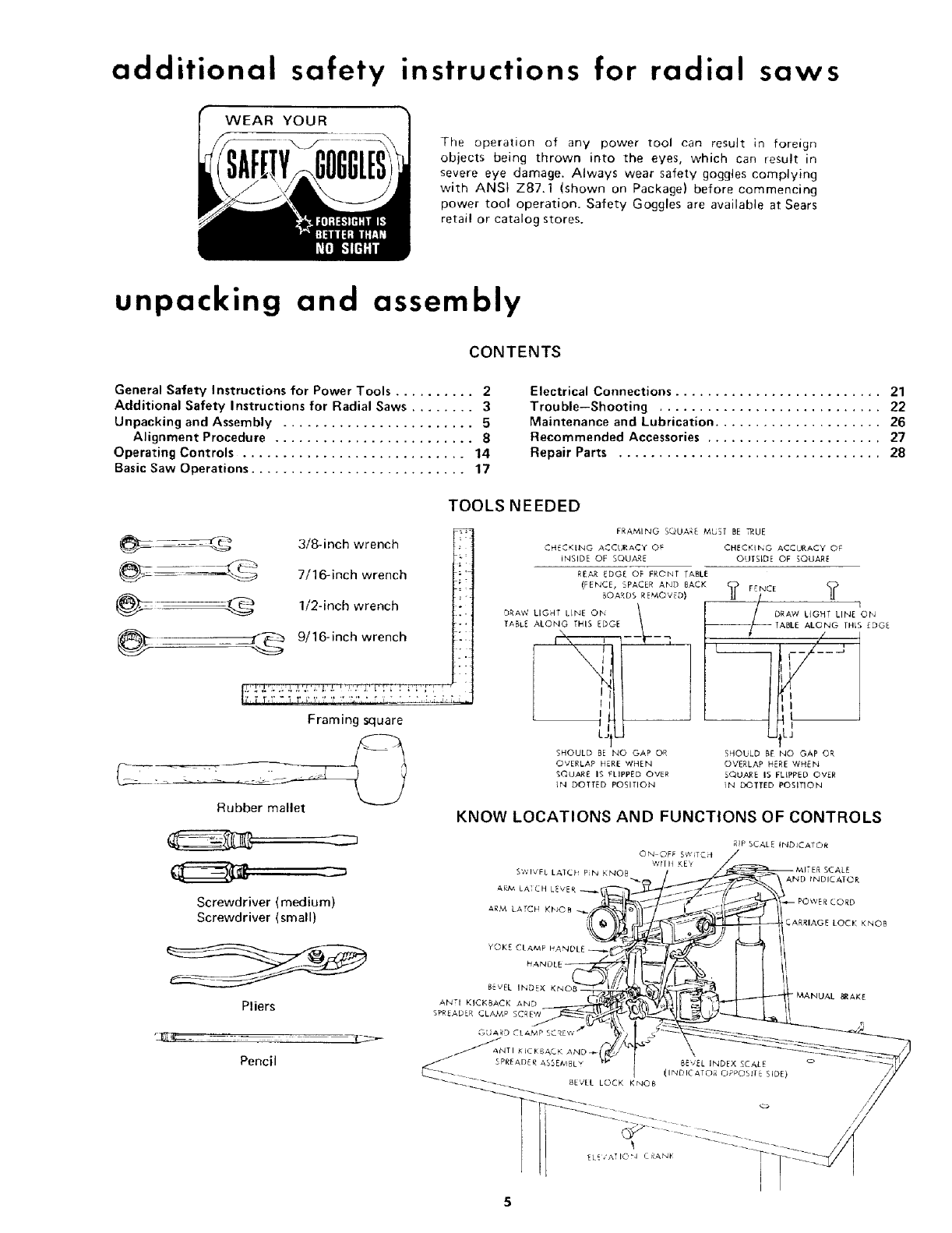
WEAR YOUR
The operation of any power tool can result in foreign
objects being thrown into the eyes, which can result in
severe eye damage. Always wear safety goggles complying
with ANSI Z87.1 (shown on Package) before commencing
power tool operation. Safety Goggles are available at Sears
retail or catalog stores.
unpacking and assembly
CONTENTS
General Safety Instructions for Power Tools .......... 2
Additional Safety Instructions for Radial Saws ........ 3
Unpacking and Assembly ........................ 5
Alignment Procedure ......................... 8
Operating Controls ............................ 14
Basic Saw Operations ........................... 17
Electrical Connections .......................... 21
Trouble--Shooting ............................ 22
Maintenance and Lubrication ..................... 26
Recommended Accessories ...................... 27
Repair Parts ................................. 28
@-_e_---_ 3/8-inch wrench
__ 7/16-inch wrench
_._ 1/2-inch wrench
@ _ 9/16-inch wrench
Framing square
Rubber mallet
Screwdriver (medium)
Screwdriver {small)
Pliers
Pencil
TOOLS NEEDED
FRAMING SQUARE MUEE BE _UE
CH_CKING ACCURACY O F CHECKING ACCURACY OF
INSIDE OF SQUARE OUTSIDE OF SQUARE
RE#,R EDGE OF FRONT TABLE
(FENCE, SPACER AND BACK ? FENCE ?
BOARDSSE_'O"EDI /__--_--
:)RAW LIGHT LINE ON DRAW !.]GHT LINE ON
TABLE ALONG THiS EDGE
TABLE ALONG THIS EDGE --_
LJIU
SHOULD BE NO GAP OR
OVERLAP HERE WHEN
SQUARE IS FLIPPED OVER
IN DOTTED POSITION
,,/
L__ I..... ;
UttJ
SHOULD BE NO GAP OR
OVERLAP HERE WHEN
SQUARE 15 FLIPPED OVER
iN DOTTED POSITION
KNOW LOCATIONS AND FUNCTIONS OF CONTROLS
5
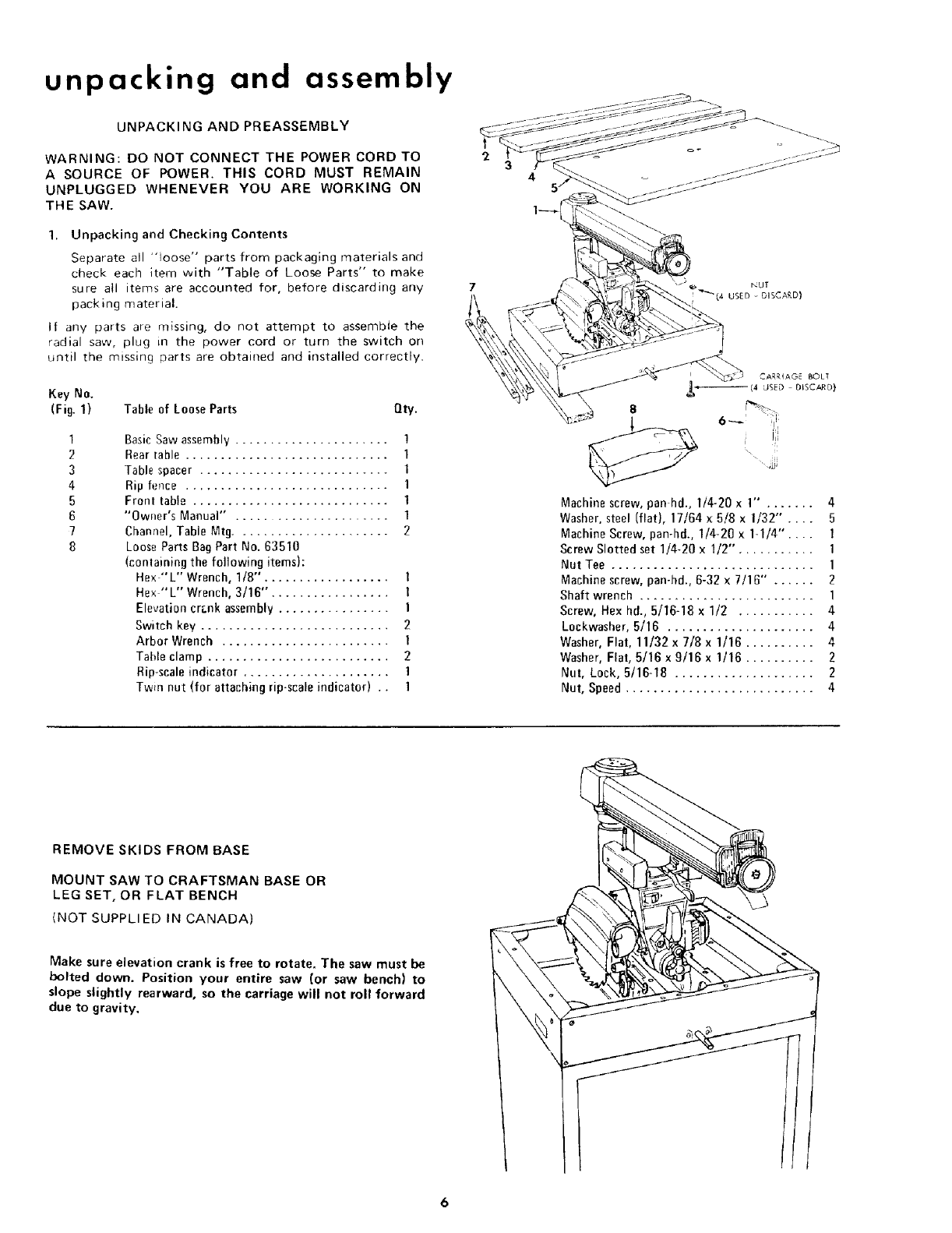
unpacking and assembly
UNPACKING AND PREASSEMBLY
WARNING: DO NOT CONNECT THE POWER CORD TO
ASOURCE OF POWER. THIS CORD MUST REMAIN
UNPLUGGED WHENEVER YOU ARE WORKING ON
THE SAW.
1. Unpacking and Checking Contents
Separate all "loose" parts from packaging materials and
check each item with "Table of Loose Parts" to make
sure all items are accounted for, before discarding any
packing material.
if any parts are missing, do not attempt to assemble the
radial saw, plug in the power cord or turn the switch on
until the missing parts are obtained and installed correctly.
Key No.
(Fig. 1) Table of Loose Parts Qty.
1
2
3
4
5
6
7
8
Basic Saw assembly ...................... 1
Rear table ............................. 1
Table spacer ........................... 1
Rip fence ............................. 1
Front table ............................ 1
"Owner's Manual" . .................... 1
Channel, Table Mtg...................... 2
Loose Parts Bag Part No. 63510
(conlaining the following items):
Hex "L" Wrench, 1/8"'. ................. 1
Hex "'L" Wrench, 3/16". ................ 1
Elevation crank assembly ................ 1
Switch key ........................... 2
Arbor Wrench ........................ 1
Table clamp .......................... 2
Rip-scale indicator ..................... 1
Twin nut (for attaching rip-scale indicator) .. l
CARRIAGE BOLT
,L.,_ (4 LJSED DfSCAR D}
8
_6_ ¸ il!j
i i_l:i'
Machine screw, pan hd., 1/4-20 x1" ....... 4
Washer, steel (flat), 17/64 x 5/8 x 1/32" .... 5
Machine Screw, pan-hal., 1/4-20 x 1-1/4".... 1
Screw Slotted set 1/4-20 x 1/2". .......... 1
Nut Tee ............................. 1
Machine screw, pan-hd., 6-32 x 7/16" ...... 2
Shaft wrench ......................... 1
Screw, Hex hd., 5/16-18 x 1/2 ........... 4
Lockwasher, 5/16 ..................... 4
Washer, Flat, 11/32 x 7/8 x 1/16 .......... 4
Washer, Flat, 5/16 x 9/16 x1/16 .......... 2
Nut, Lock, 5/16-18 .................... 2
Nut, Speed ........................... 4
REMOVE SKIDS FROM BASE
MOUNT SAW TO CRAFTSMAN BASE OR
LEG SET, OR FLAT BENCH
{NOT SUPPLI ED IN CANADA)
Make sure elevation crank is free to rotate. The saw must be
bolted down. Position your entire saw (or saw bench) to
slope slightly rearward, so the carriage will not roll forward
due to gravity.
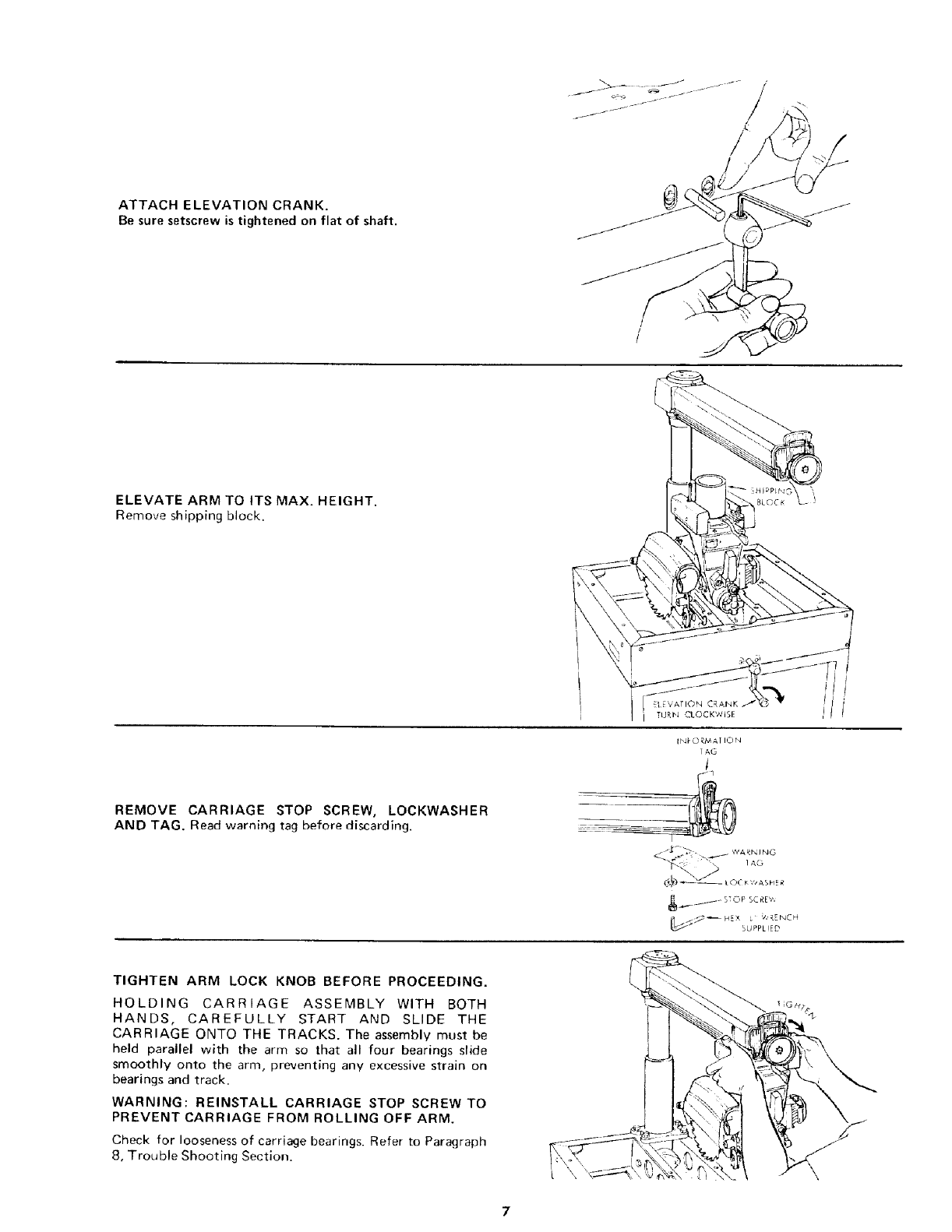
ATTACH ELEVATION CRANK.
Be sure setscrew is tightened on flat of shaft.
ELEVATE ARM TO ITS MAX. HEIGHT.
Remove shipping block.
REMOVE CARRIAGE STOP SCREW,
AND TAG. Read warning tag before discarding.
LOCKWASHER
INJ'O RMAT ION
1
11
i_ _- STOP SCREV,
SUPPL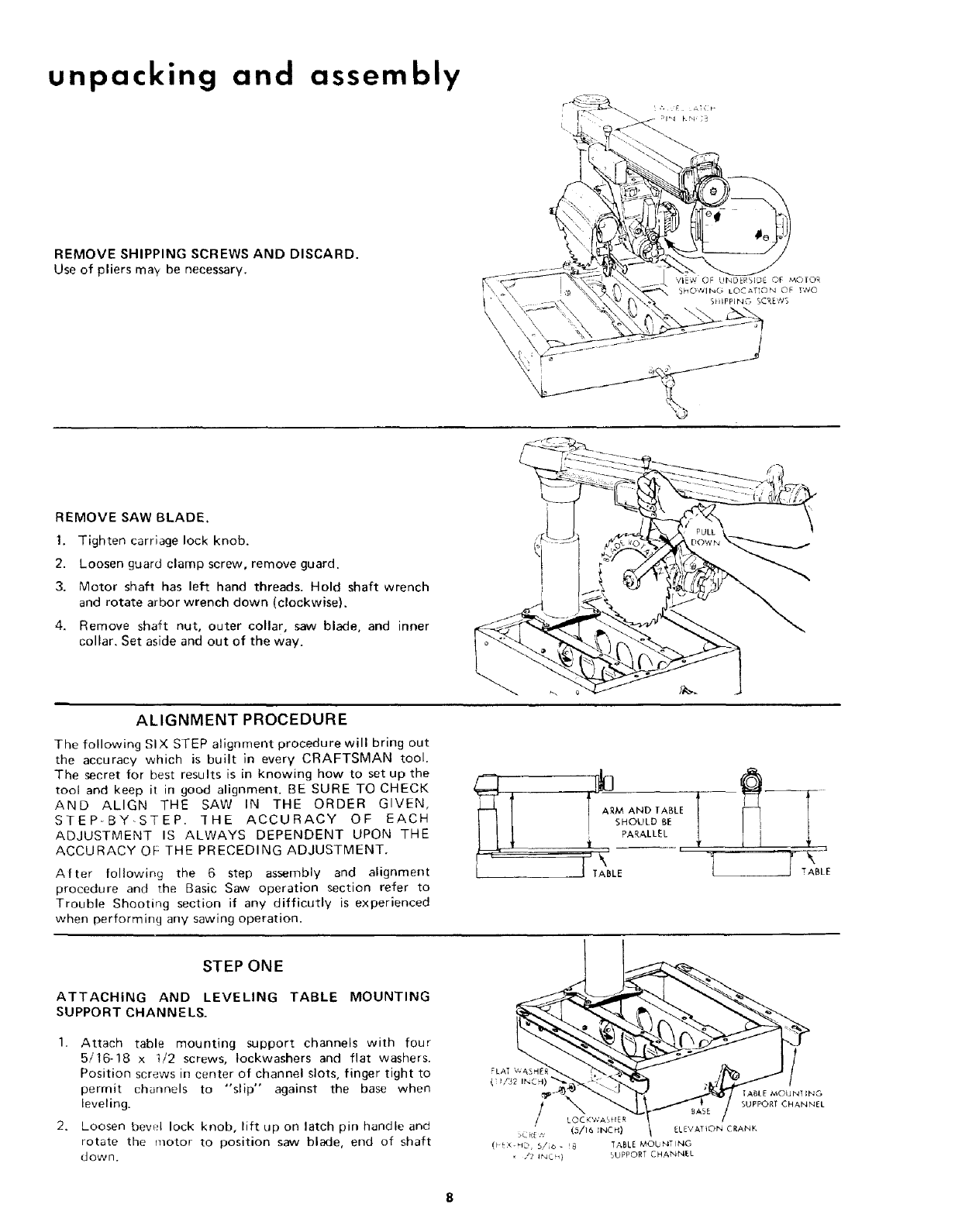
unpacking and assembly
REMOVE SHIPPING SCREWS AND DISCARD.
Use of pliers may be necessary.
,
\
\
REMOVE SAW BLADE.
1. Tighten carriage lock knob.
2. Loosen guard clamp screw, remove guard.
3. Motor shaft has left hand threads. Hold shaft wrench
and rotate arbor wrench down (clockwise).
4. Remove shaft nut, outer collar, saw blade, and inner
collar. Set aside and out of the way.
ALIGNMENTPROCEDURE
The following SIX STEP alignment procedure will bring out
the accuracy which is built in every CRAFTSMAN tool.
The secret for best results is in knowing how to set up the
tool and keep it in good alignment. BE SURE TO CHECK
AND ALIGN THE SAW IN THE ORDER GIVEN,
STEP-BY-STEP. "THE ACCURACY OF EACH
ADJUSTMENT IS ALWAYS DEPENDENT UPON THE
ACCURACY OF: THE PRECEDING ADJUSTMENT.
After following the 6 step assembly and alignment
procedure and the Basic Saw operation section refer to
Trouble Shooting section if any difficutly is experienced
when performing any sawing operation.
/ SHOULDBE !
_ PARALLEL __
,_ -
I TABLE 1
STEP ONE
ATTACHING AND LEVELING TABLE MOUNTING
SUPPORT CHANNELS.
1. Attach table mounting support channels with four
5/16-18 x 1/2 screws, tockwashers and flat washers.
Position screws in center of channel slots, finger tight to
permit channels to "slip" against the base when
leveling.
2. Loosen bewfl lock knob, lift up on latch pin handle and
rotate the motor to position saw blade, end of shaft
down.
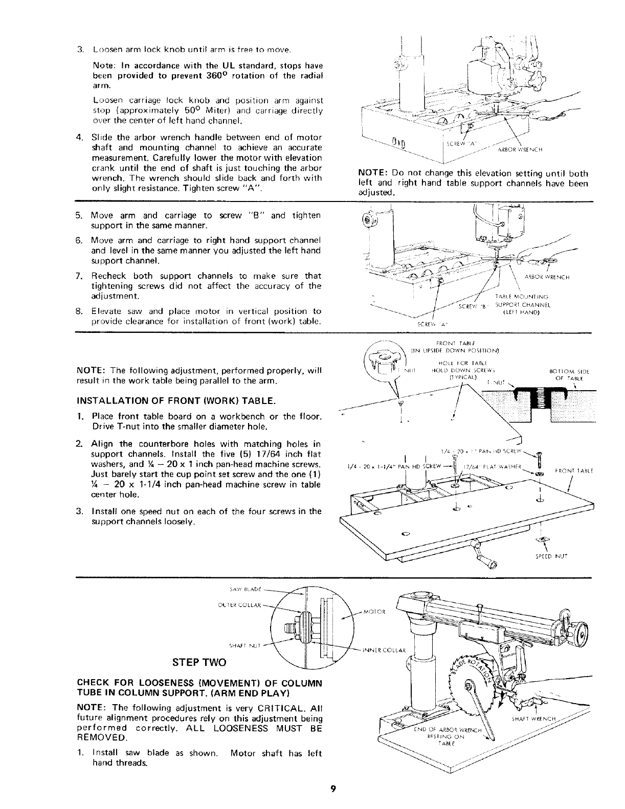
3. Loosenarmlockknobuntilarmisfreetomove.
Note:In accordance with the UL standard, stops have
been provided to prevent 360 ° rotation of the radial
arm.
Loosen carriage lock knob and position arm against
stop {approximately 50 ° Miter) and carriage directly
over the center of left hand channel.
4. Slide the arbor wrench handle between end of motor
shaft and mounting channel to achieve an accurate
measurement. Carefully lower the motor with elevation
crank until the end of shaft is just touching the arbor
wrench. The wrench should slide back and forth with
only slight resistance. Tighten screw "A".
!
L..... ._ 0_fj SCRE,,''A .-''z"
I . ARBOR _,','REN C H
//
NOTE: Do not change this elevation setting until both
left and right hand table support channels have been
adjusted.
5. Move arm and carriage to screw "B" and tighten
support in the same manner.
6. Move arm and carriage to right hand support channel
and level in the same manner you adjusted the left hand
support channel.
7. Recheck both support channels to make sure that
tightening screws did not affect the accuracy of the
adjustment.
8. Elevate saw and place motor in vertical position to
provide clearance for installation of front (work) table.
/
\, ARBOR WRENCH
\
TABLE MOLINT ING
SUPPORT CHANNEL
(LEFT HAND)
NOTE: The following adjustment, performed properly, will
result in the work table being parallel to the arm.
INSTALLATION OF FRONT (WORK) TABLE.
1. Place front table board on a workbench or the floor.
Drive T-nut into the smaller diameter hole.
2. Align the counterbore holes with matching holes in
support channels. Install the five (5) 17/64 inch flat
washers, and ¼ - 20 x 1 inch pan-head machine screws.
Just barely start the cup point set screw and the one (1)
Y4 - 20 x 1-1/4 inch pan-head machine screw in table
center hole.
3. Install one speed nut on each of the four screws in the
support channels loosely.
I
1/4 20 * I-I/4" PAN HD
_) TTOM SIDE
OF TABLE
\
SPEED NUT
CHECK FOR LOOSENESS (MOVEMENT) OF COLUMN
TUBE IN COLUMN SUPPORT. (ARM END PLAY)
NOTE: The following adjustment is very CRITICAL. All
future alignment procedures rely on this adjustment being
performed correctly. ALL LOOSENESS MUST BE
REMOVED.
1. Install saw blade as shown. Motor shaft has left
hand threads.
SHAFT WRENCH
unpacking and assembly
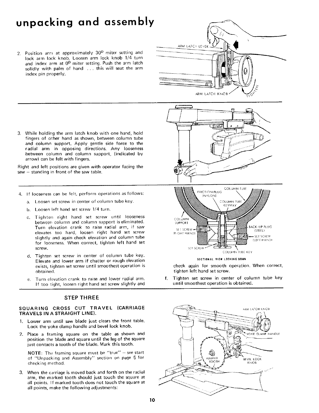
Position arm at approximately 30 ° miter setting and
lock arm lock knob. Loosen arm lock knob I/4 turn
and index arm at 0° miter setting. Push the arm latch
solidly with palm of hand ... this will seat the arm
index pin properly.
ARM LATCH LEVER
ARM LATCH KNOB
3. While holding the arm latch knob with one hand, hold
fingers of o_her hand as shown, between column tube
and column support. Apply gentle side force to the
radial arm in opposing directions. Any looseness
between column and column support, (indicated by
arrow) can be felt with fingers.
Right and left positions are given with operator facing the
saw - standing in front of the saw table.
4. If looseness earl be felt, perform operations as follows:
a. Loosen set screw in center of column tube key.
b. Loosen left hand set screw 1/4 turn.
Tighten right hand set screw until looseness
between column and column support is eliminated.
Turn elevation crank to raise radial arm, if saw
elevates too hard, loosen right hand set screw
slightly and again check elevation and column tube
for looseness. When correct, tighten left hand set
screw.
d. Tighten set screw in center of column tube key.
Elevate and lower arm if chatter or rough elevation
exists, tighten set screw until smoothest operation is
obtained.
e. Turn elevation crank to raise and lower radial arm.
If too tight, loosen right hand set screw slightly and
FRICTION PLUG
(NYLON)
STEP THREE
SQUARING CROSS CUT TRAVEL (CARRIAGE
TRAVELS IN A STRAIGHT LINE).
1. Lower arm until saw blade just clears the front table.
Lock the yoke clamp handle and bevel lock knob.
2. Place a framing square on the table as shown and
position the blade and square until the leg of the square
just contacts a tooth of the blade. Mark this tooth.
NOTE: The framing square must be "true" - see start
of "Unpacking and Assembly" section on page 5 for
checking method.
When the carriage is moved back and forth on the radial
arm, the marked tooth should just touch the square at
all points. If marked tooth does not touch the square at
all points, make the following adjustments:
COLUMN
_UPPOR [
_ BACK-UP _[UG
SET SCREW- (STEED
{RIGHT HAND)
(LEF[ HAND)
_ET SCR_
COLUMN tUBE KEY
SECTIONAL V_EW LOOKINg DOWN
check again for smooth operation. When correct,
tighten left hand set screw,
Tighten set screw in center of column tube key
until smoothest operation is obtained.
_YOKE CLAMP HANDLE
BEVEL LOCK
KNOB
10
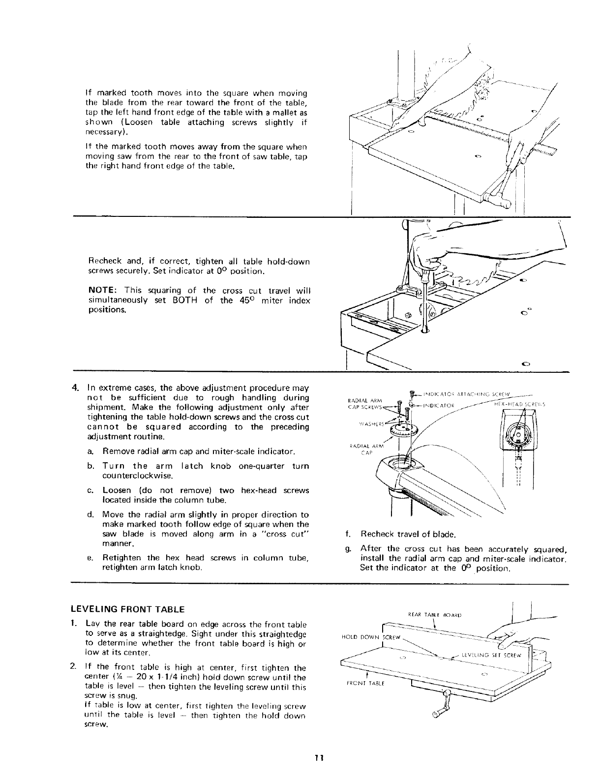
If marked tooth moves into the square when moving
the blade from the rear toward the front of the table,
tap the left hand front edge of the table with a mallet as
shown (Loosen table attaching screws slightly if
necessary).
If the marked tooth moves away from the square when
moving saw from the rear to the front of saw table, tap
the right hand front edge of the table.
Recheck and, if correct, tighten all table hold-down
screws securely. Set indicator at 0 ° position.
NOTE: This squaring of the cross cut travel will
simultaneously set BOTH of the 45 ° miter index
positions.
o
4. In extreme cases, the above adjustment procedure may
not be sufficient due to rough handling during
shipment. Make the following adjustment only after
tightening the table hold-down screws and the cross cut
cannot be squared according to the preceding
adjustment routine.
a. Remove radial arm cap and miter-scale indicator.
b. Turn the arm latch knob one-quarter turn
counterclockwise.
c. Loosen (do not remove) two hex-head screws
located inside the column tube.
d. Move the radial arm slightly in proper direction to
make marked tooth follow edge of square when the
saw blade is moved along arm in a "cross cut"
manner.
e. Retighten the hex head screws in column tube,
retighten arm latch knob.
f,
g.
Recheck travel of blade.
After the cross cut has been accurately squared,
install the radial arm cap and miter-scale indicator.
Set the indicator at the 0° .position.
LEVELING FRONT TABLE
Lay the rear table board on edge across the front table
to serve as a straightedge. Sight under this straightedge
to determine whether the front table board is high or
low at its center.
2. If the front table is high at center, first tighten the
center (¼ -20x 1-1/4 inch) hold down screw until the
table is level -- then tighten the leveling screw until this
screw is snug.
If table is low at center, first tighten the leveling screw
until the table is level -- then tighten the hold down
screw.
RRAR TAB[[ 6OAR[3 1_
11
unpacking and assembly
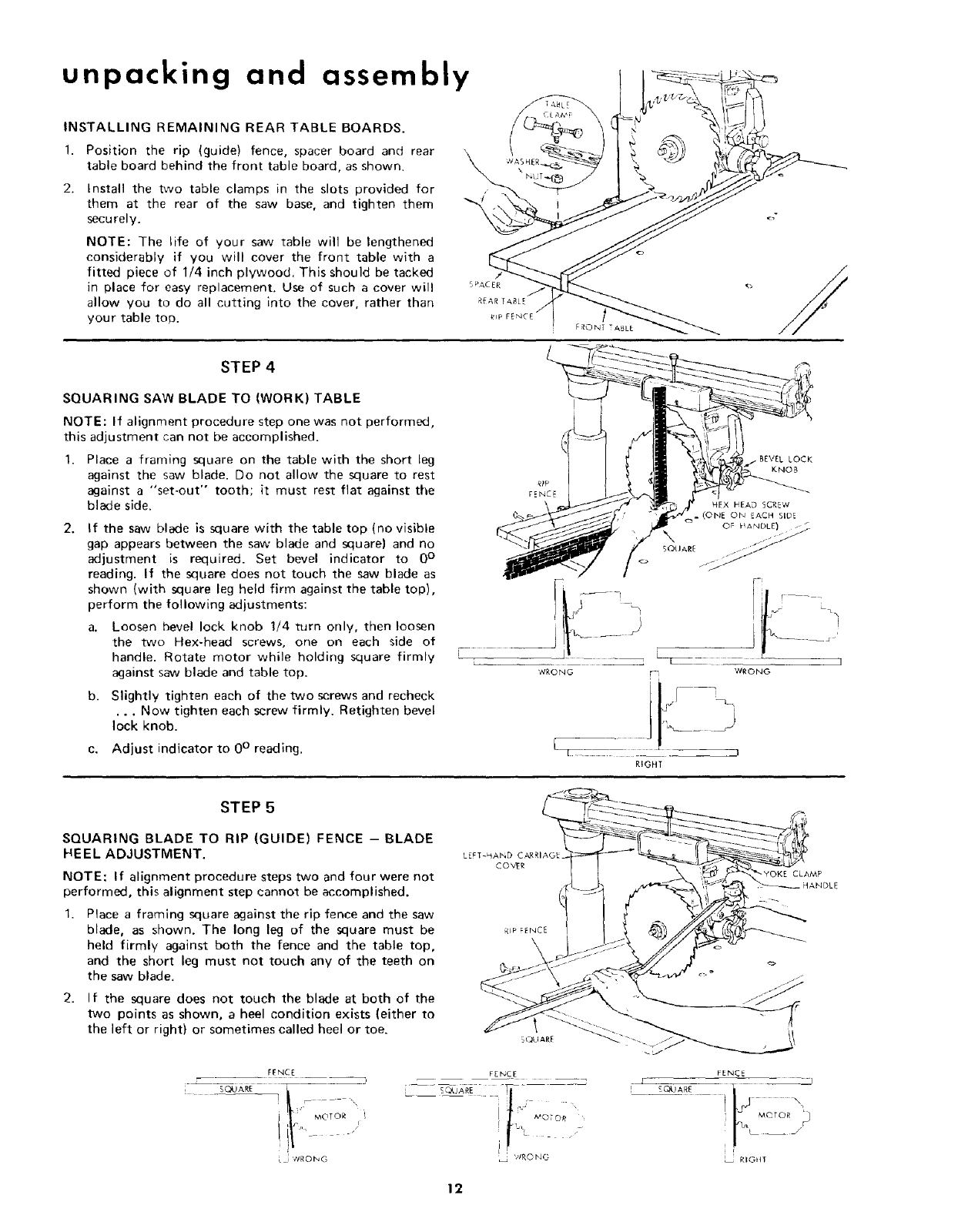
INSTALLING REMAINING REAR TABLE BOARDS•
1. Position the rip (guide) fence, spacer board and rear
table board behind the front table board, as shown.
2. Install the two table clamps in the slots provided for
them at the rear of the saw base, and tighten them
securely.
NOTE: The life of your saw table wil] be lengthened
considerably if you will cover the front table with a
fitted piece of 1/4 inch plywood. This should be tacked
in place for easy replacement. Use of such a cover will
allow you to do all cutting into the cover, rather than
your table top. FRONT TABLE
STEP 4
SQUARING SAW BLADE TO (WORK) TABLE
NOTE: If alignment procedure step one was not performed,
this adjustment can not be accomplished.
Place a framing square on the table with the short leg
against the saw blade. Do not allow the square to rest
against a "set-out" tooth; it must rest fiat against the
blade side.
If the saw blade is square with the table top (no visible
gap appears between the saw blade and square) and no
adjustment is required. Set bevel indicator to 0 °
reading• If the square does not touch the saw blade as
shown (with square leg held firm against the table top),
perform the following adjustments:
a. Loosen bevel lock knob 1/4 turn only, then loosen
the two Hex-head screws, one on each side of
handle. Rotate motor while holding square firmly
against saw blade and table top.
b. Slightly tighten each of the two screws and recheck
•.. Now tighten each screw firmly. Retighten bevel
lock knob.
c. Adjust indicator to 0 ° reading.
STEP 5
SQUARING BLADE TO RIP (GUIDE) FENCE -BLADE
HEEL ADJUSTMENT.
NOTE: If alignment procedure steps two and four were not
performed, this alignment step cannot be accomplished.
Place aframing square against the rip fence and the saw
blade, as shown. The long leg of the square must be
held firmly against both the fence and the table top,
and the short leg must not touch any of the teeth on
the saw blade.
2. If the square does not touch the blade at both of the
two points as shown, a heel condition exists (either to
the left or right) or sometimes called heel or toe. QUARE
---- FENCE ----
" MOTOR i !
-/
.j ¢_RONG WRONG
CLAMP
FENC5
! MOTOR _]
r
RIGHI
12
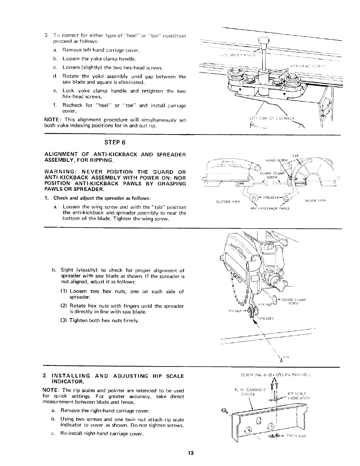
3. To correct for either type of "heel" or "toe" condition
proceed as follows:
a. Remove left hand carriage cover.
b. Loosen the yoke clamp handle.
c. Loosen (slightly) the two hex-head screws•
d. Rotate the yoke assembly until gap between the
saw blade and square is eliminated.
e. Lock yoke clamp handle and retighten the two
hex-head screws.
f. Recheck for "heel" or "toe" and install carriage
cover.
NOTE: This alignment procedure will simultaneously set
both yoke indexing positions for in and out rip.
STEP 6
ALIGNMENT OF ANTI-KICKBACK AND SPREADER
ASSEMBLY, FOR RIPPING.
WARNING: NEVER POSITION THE GUARD OR
ANTI-KICKBACK ASSEMBLY WITH POWER ON; NOR
POSITION ANTI-KICKBACK PAWLS BY GRASPING
PAWLS OR SPREADER.
1. Check and adjust the spreader as follows:
a. Loosen the wing screw and with the "tab" position
the anti-kickback and spreader assembly to near the
bottom of the blade. Tighten the wing screw.
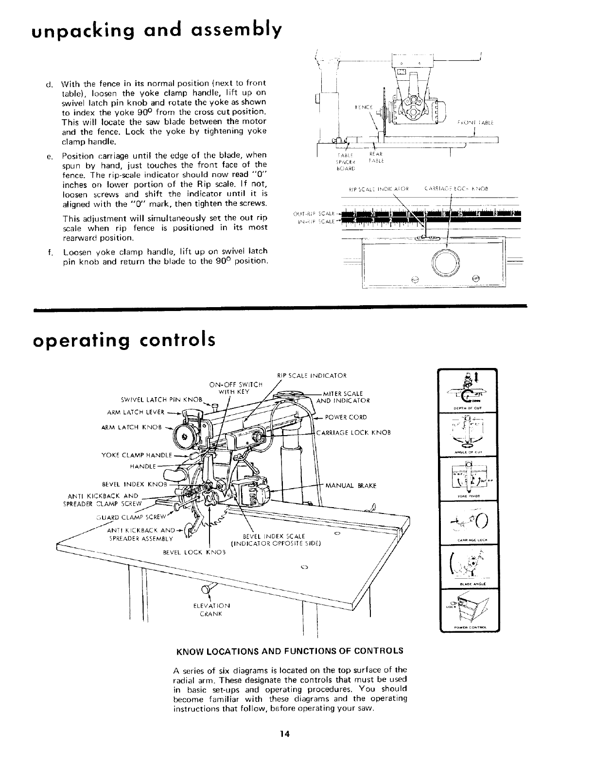
b. Sight (visually) to check for proper alignment of
spreader with saw blade as shown. If the spreader is
not aligned, adjust it as follows:
OUTSIDE VIEW
(1) Loosen two hex nuts, one on each side of
spreader.
(2) Rotate hex nuts with fingers until the spreader
is directly in line with saw blade.
(3) Tighten both hex nuts firmly.
\ 4_r
HEX NUT _
2- INSTALLING AND ADJUSTING RIP SCALE
INDICATOR.
NOTE: The rip scales and pointer are intended to be used
for quick settings. For greater accuracy, take direct
measurement between blade and fence.
a. Remove the right-hand carriage cover.
b. Using two screws and one twin nut attach rip scale
indicator to cover as shown. Do not tighten screws.
c. Re-install right-hand carriage cover.
13
t/--
\\
INSIDE VIE_
unpacking and assembly
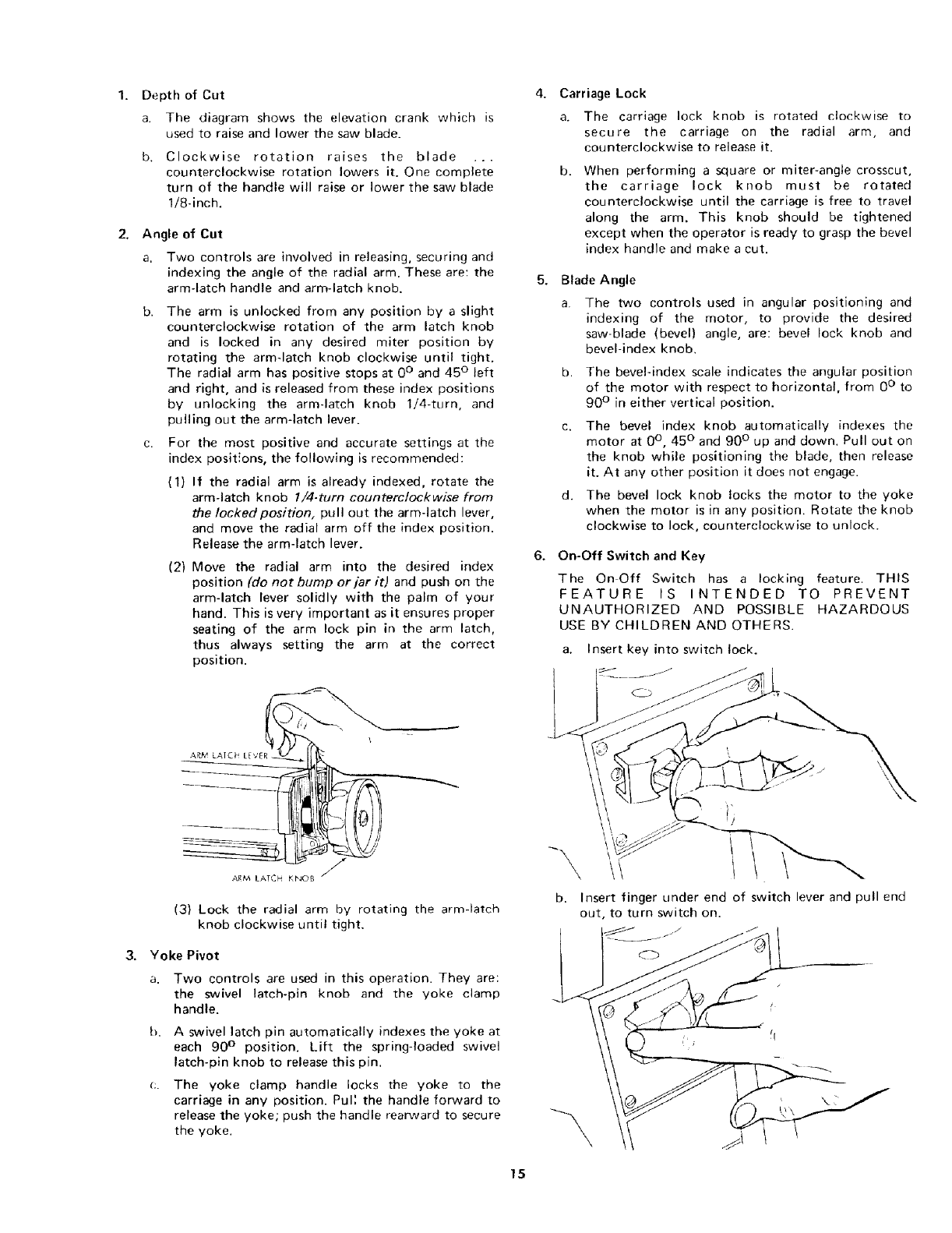
d, With the fence in its normal position (next to front
table), loosen the yoke clamp handle, lift up on
swivel latch pin knob and rotate the yoke as shown
to index the yoke 90 ° from the cross cut position.
This will locate the saw blade between the motor
and the fence. Lock the yoke by tightening yoke
clamp handle.
e. Position carriage until the edge of the blade, when
spun by hand, just touches the front face of the
fence. The rip-scale indicator should now read "0"
inches on lower portion of the Rip scale. If not,
loosen screws and shift the indicator until it is
aligned with the "0" mark, then tighten the screws.
This adjustment will simultaneously set the out rip
scale when rip fence is positioned in its most
rearward position.
f. Loosen yoke clamp handle, lift up on swivel latch
pin knob and return the blade to the g0 ° position.
[, ;ai'
I r4_17 R{AR I
bOARD
RfF _CAL INDI," A[OR C_\RRIAC'. [OC, t'_08
OUT RI <_
IN-Ri7
©
@ ®
operating controls
SWIVEL LATCH PIN KNOB
ARM LATCH
ARM LATCH KNOB
YOKE CLAMP
RiP SCALE INDICATOR
ON-OFF SWJ1CH
WITH KEY
AND INDICATOR
_ARRIAGE LOCK KNOB
BEVEL INDEX
ANT! KICKBACK AND
SPREADER CLAMP SCREW
L_UARD CLAMP SC
ANTI KICKBACK AND-,._
SPREADER ASSEMBLY
BEVEL LOCK KNO5
MANUAL BRAKE
BEVEL INDEX SCALE o
(INDICATOR OPPOSITE SIDE)
ELEVATION
CRANK
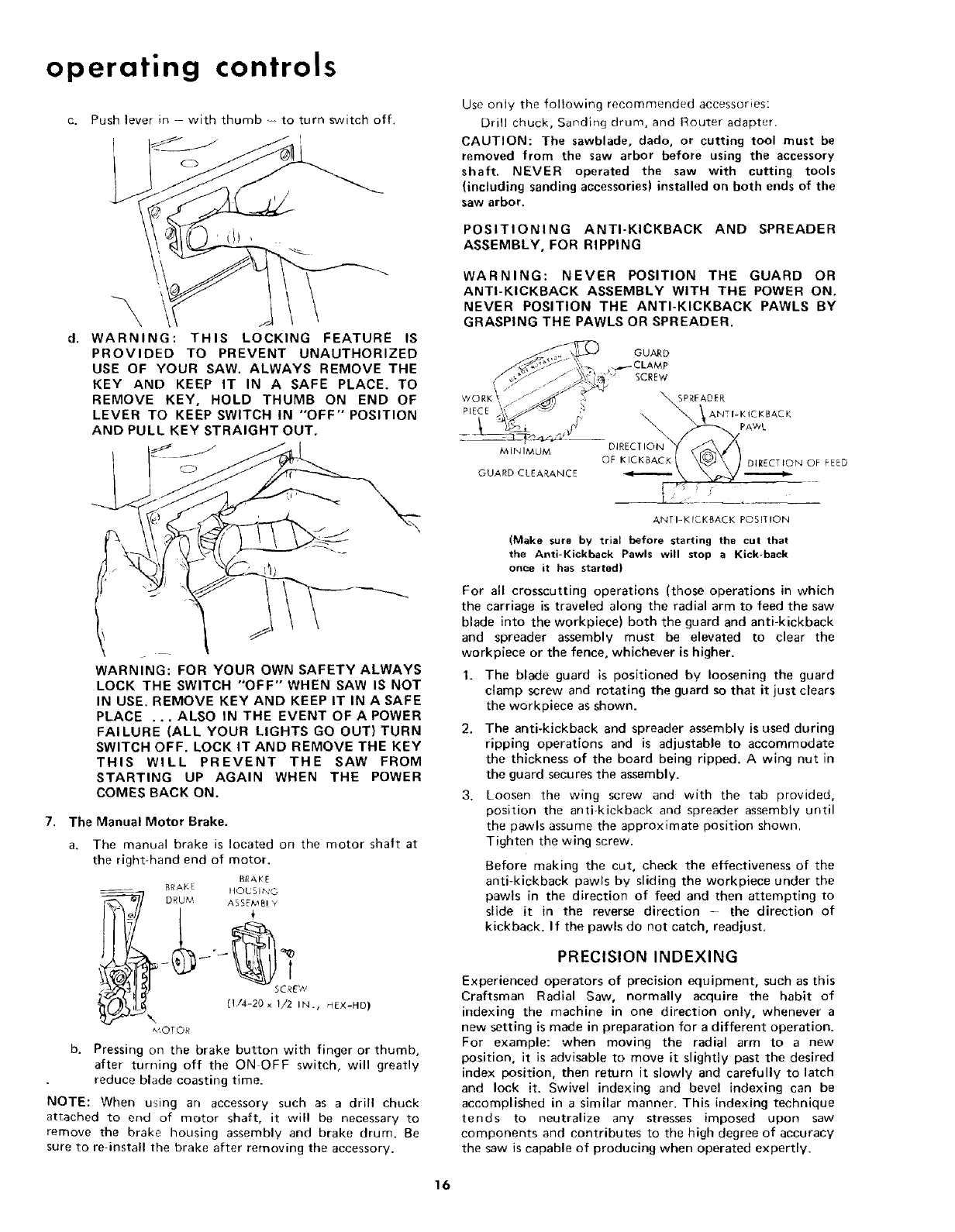
KNOW LOCATIONS AND FUNCTIONS OF CONTROLS
A series of six diagrams is located on the top surface of the
radial arm. These designate the controls that must be used
in basic set-ups and operating procedures. You should
become familiar with these diagrams and the operating
instructions that follow, before operating your saw.
nu_oe AnGLe
14
Depth of Cut
a. The diagram shows the elevation crank which is
used to raise and lower the saw blade.
b. Clockwise rotation raises the blade ...
counterclockwise rotation lowers it. One complete
turn of the handle will raise or lower the saw blade
1/8-inch.
Angle of Cut
a. Two controls are involved in releasing, securing and
indexing the angle of the radial arm. These are: the
arm-latch handle and arm-latch knob.
b. The arm is unlocked from any position by a slight
counterclockwise rotation of the arm latch knob
and is locked in any desired miter position by
rotating the arm-latch knob clockwise until tight.
The radial arm has positive stops at 0 ° and 45 ° left
and right, and is released from these index positions
by unlocking the arm-latch knob 1!4-turn, and
pulling out the arm-latch lever.
For the most positive and accurate settings at the
index posit_ons, the following is recommended:
{1) If the radial arm is already indexed, rotate the
arm-latch knob 1i4-tum counterclockwise from
the Iockedposition, pull out the arm-latch lever,
and move the radial arm off the index position.
Release the arm-latch lever.
(2) Move the radial arm into the desired index
position (do not bump or jar it) and push on the
arm-latch lever solidly with the palm of your
hand. This is very important as it ensures proper
seating of the arm lock pin in the arm latch,
thus always setting the arm at the correct
position.
5.
Carriage Lock
a. The carriage lock knob is rotated clockwise to
secure the carriage on the radial arm, and
counterclockwise to release it.
b. When performing a square or miter-angle crosscut,
the carriage lock knob must be rotated
counterclockwise until the carriage is free to travel
along the arm. This knob should be tightened
except when the operator is ready to grasp the bevel
index handle and make a cut.
6.
Blade Angle
a. The two controls used in angular positioning and
indexing of the motor, to provide the desired
saw-blade (bevel) angle, are: bevel lock knob and
bevel-index knob.
b. The bevel-index scale indicates the angular position
of the motor with respect to horizontal, from 0 ° to
90 ° in either vertical position.
c. The bevel index knob automatically indexes the
motor at 0°, 45 ° and 90 ° up and down. Pull out on
the knob while positioning the blade, then release
it. At any other position it does not engage.
d. The bevel lock knob locks the motor to the yoke
when the motor is in any position. Rotate the knob
clockwise to lock, counterclockwise to unlock.
On-Off Switch and Key
The On Off Switch has a locking feature. THIS
FEATURE IS INTENDED TO PREVENT
UNAUTHORIZED AND POSSIBLE HAZARDOUS
USE BY CHILDREN AND OTHERS.
a. Insert key into switch lock.
jJ
ARM LATCH KNOB
(3) Lock the radial arm by rotating the arm-latch
knob clockwise until tight.
Yoke Pivot
a. Two controls are used in this operation. They are:
the swivel latch-pin knob and the yoke clamp
handle.
h. A swivel latch pin automatically indexes the yoke at
each 90 ° position. Lift the spring-loaded swivel
latch-pin knob to release this pin.
The yoke clamp handle locks the yoke to the
carriage in any position. Pull the handle forward to
release the yoke; push the handle rearward to secure
the yoke.
-\, l
b. Insert finger under end of switch lever and pull end
out, to turn switch on.
_f jj_
15
operating controls
C. Push lever in with thumb -- to turn switch off.
WARNING: THIS LOCKING FEATURE IS
PROVIDED TO PREVENT UNAUTHORIZED
USE OF YOUR SAW. ALWAYS REMOVE THE
KEY AND KEEP IT IN A SAFE PLACE. TO
REMOVE KEY, HOLD THUMB ON END OF
LEVER TO KEEP SWITCH IN "OFF" POSITION
AND PULL KEY STRAIGHT OUT.
o
WARNING: FOR YOUR OWN SAFETY ALWAYS
LOCK THE SWITCH "'OFF" WHEN SAW IS NOT
IN USE. REMOVE KEY AND KEEP IT IN A SAFE
PLACE ...ALSO IN THE EVENT OFAPOWER
FAILURE (ALL YOUR LIGHTS GO OUT} TURN
SWITCH OFF. LOCK IT AND REMOVE THE KEY
THIS WILL PREVENT THE SAW FROM
STARTING UP AGAIN WHEN THE POWER
COMES BACK ON.
7. The Manual Motor Brake.
The manual brake is located on the motor shaft at
the right-hand end of motor.
BRAKE
____ BRAKE HOUSING
DRUM ASSEM_! Y
I
SCREW
(1/4-20x I/2 IN., HLX-HD)
\
,V,OT OR
b. Pressing on the brake button with finger or thumb,
after turning off the ON OFF switch, will greatly
reduce blade coasting time.
NOTE: When using an accessory such as a drill chuck
attached to end of motor shaft, it ,,,viii be necessary to
remove the brake housing assembly and brake drum. Be
sure to re-install the brake after removing the accessory.
Use only the following recommended accessories:
Drill chuck, Sanding drum, and Router adapter.
CAUTION: The sawblade, dado, or cutting tool must be
removed from the saw arbor before using the accessory
shaft. NEVER operated the saw with cutting tools
(including sanding accessories) installed on both ends of the
saw arbor.
POSITIONING ANTI-KICKBACK AND SPREADER
ASSEMBLY, FOR RIPPING
WARNING: NEVER POSITION THE GUARD OR
ANTI-KICKBACK ASSEMBLY WITH THE POWER ON.
NEVER POSITION THE ANTI-KICKBACK PAWLS BY
GRASPING THE PAWLS OR SPREADER.
WORK_,
PIECE
MINIMUM
GUARD CLEARANCE
GUARD
_,7 SCREW
ANTI-KICKBACK POSITION
(Make sure by trial before starting the cut that
the Anti-Kickback Pawls will stop a Kick-beck
once it has started)
For all crosscutting operations (those operations in which
the carriage is traveled along the radial arm to feed the saw
blade into the workpiece) both the guard and anti-kickback
and spreader assembly must be elevated to clear the
workpiece or the fence, whichever is higher.
1. The blade guard is positioned by loosening the guard
clamp screw and rotating the guard so that it just clears
the workpiece as shown.
2. The anti-kickback and spreader assembly is used during
ripping operations and is adjustable to accommodate
the thickness of the board being ripped. A wing nut in
the guard secures the assembly.
3. Loosen the wing screw and with the tab provided,
position the anti-kickback and spreader assembly until
the pawls assume the approximate position shown.
Tighten the wing screw.
Before making the cut, check the effectiveness of the
anti-kickback pawls by sliding the workpiece under the
pawls in the direction of feed and then attempting to
slide it in the reverse direction -the direction of
kickback. If the pawls do not catch, readjust.
PRECISION INDEXING
Experienced operators of precision equipment, such as this
Craftsman Radial Saw, normally acquire the habit of
indexing the machine in one direction only, whenever a
new setting is made in preparation for a different operation.
For example: when moving the radial arm to a new
position, it is advisable to move it slightly past the desired
index position, then return it slowly and carefully to latch
and lock it. Swivel indexing and bevel indexing can be
accomplished in a similar manner. This indexing technique
tends to neutralize any stresses imposed upon saw
components and contributes to the high degree of accuracy
the saw is capable of producing when operated expertly.
16
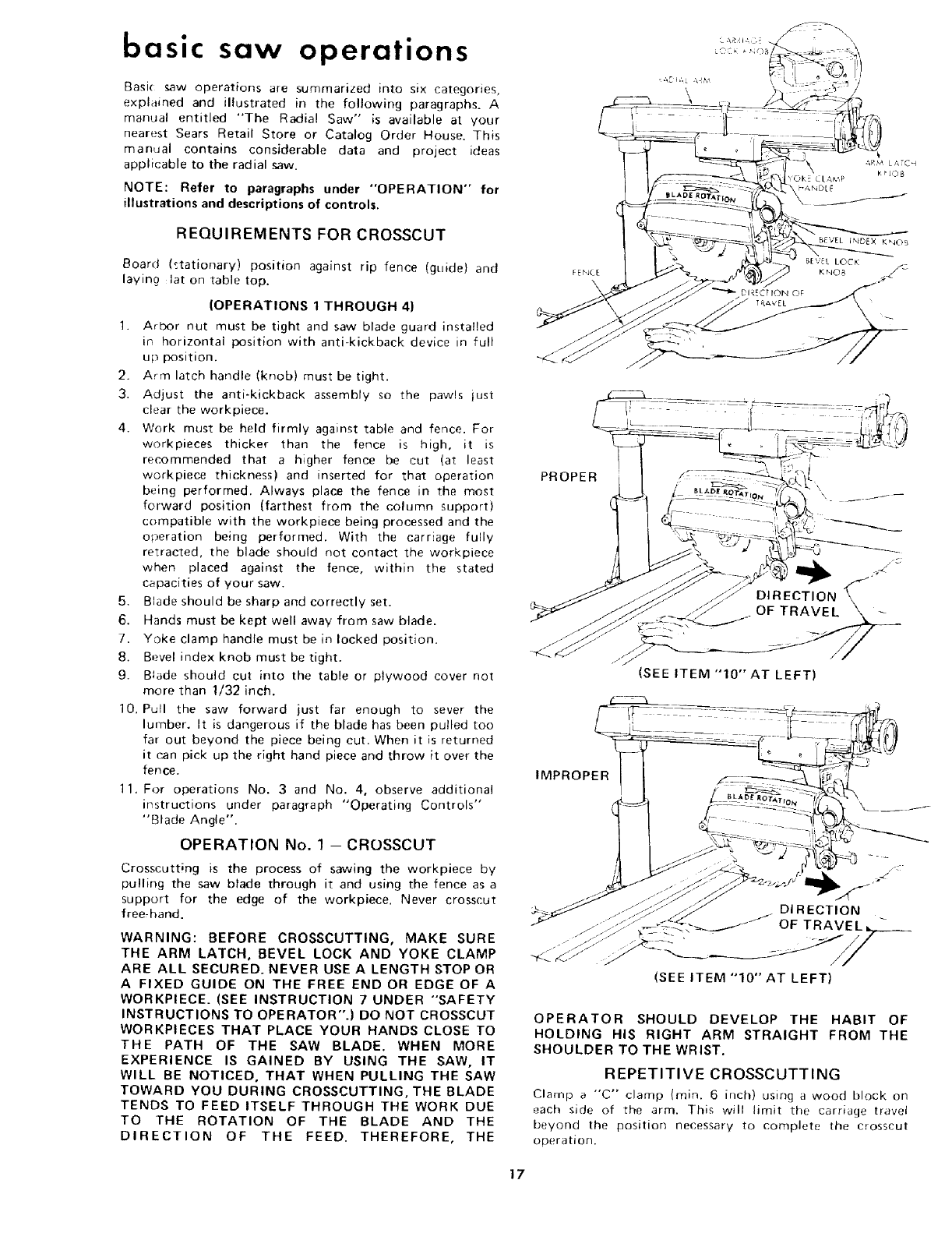
basic saw operations
Basi( saw operations are summarized into six categories,
explained and illustrated in the following paragraphs_ A
manual entitled "The Radial Saw" is available at your
nearest Sears Retail Store or Catalog Order House. This
manual contains considerable data and project ideas
applicable to the radial saw.
NOTE: Refer to paragraphs under "OPERATION" for
illustrations and descriptions of controls.
REQUIREMENTS FOR CROSSCUT
Board P,tationary) position against rip fence (guide) and
laying lat on table top.
(OPERATIONS 1 THROUGH 4)
1. Arbor nut must be tight and saw blade guard installed
in horizontal position with anti-kickback device in full
up position.
2. Arm latch handle (knob) must be tight.
3. Adjust the anti-kickback assembly so the pawls just
clear the workpiece.
4. Work must be held firmly against table and fence. For
workpieces thicker than the fence is high, it is
recommended that a higher fence be cut (at least
workpiece thickness) and inserted for that operation
being performed. Always place the fence in the most
forward position (farthest from the column support)
compatible with the workpiece being processed and the
operation being performed. With the carriage fully
retracted, the blade should not contact the workpiece
when placed against the fence, within the stated
capacities of your saw.
5. Blade should be sharp and correctly set.
6. Hands must be kept well away from saw blade.
7. Yoke clamp handle must be in locked position.
8. Bevel index knob must be tight,
9. Blade should cut into the table or plywood cover not
more than 1/32 inch.
10. Pull the saw forward just far enough to sever the
lumber. It is dangerous if the blade has been pulled too
far out beyond the piece being cut. When it is returned
it c,an pick up the right hand piece and throw it over the
fence.
11. For operations No. 3 and No. 4, observe additional
instructions under paragraph "Operating Controls"
"Blade Angle".
OPERATION No. 1 - CROSSCUT
Crosscutting is the process of sawing the workpiece by
pulling the saw blade through it and using the fence as a
support for the edge of the workpiece. Never crosscut
free, hand.
WARNING: BEFORE CROSSCUTTING, MAKE SURE
THE ARM LATCH, BEVEL LOCK AND YOKE CLAMP
ARE ALL SECURED. NEVER USE A LENGTH STOP OR
A FIXED GUIDE ON THE FREE END OR EDGE OF A
WORKPIECE. (SEE INSTRUCTION 7 UNDER "SAFETY
INSTRUCTIONS TO OPERATOR".) DO NOT CROSSCUT
WORKPIECES THAT PLACE YOUR HANDS CLOSE TO
THE PATH OF THE SAW BLADE. WHEN MORE
EXPERIENCE IS GAINED BY USING THE SAW, IT
WILL BE NOTICED, THAT WHEN PULLING THE SAW
TOWARD YOU DURING CROSSCUTTING, THE BLADE
TENDS TO FEED ITSELF THROUGH THE WORK DUE
TO THE ROTATION OF THE BLADE AND THE
DIRECTION OF THE FEED. THEREFORE, THE
PROPER
DIRECTION
,SEE'TEM",0'"AT,EFT,
IMPROPER
DI R ECTION
(SEE ITEM "10" AT LEFT)
OPERATOR SHOULD DEVELOP THE HABIT OF
HOLDING HIS RIGHT ARM STRAIGHT FROM THE
SHOULDER TO THE WRIST.
REPETITIVE CROSSCUTTING
Clamp a "'C" clamp (rain. 6 inch) using a wood block on
each side of the arm. This will limit the carriage travel
beyond the position necessary to complete the crosscut
operation.
17
basic saw operations
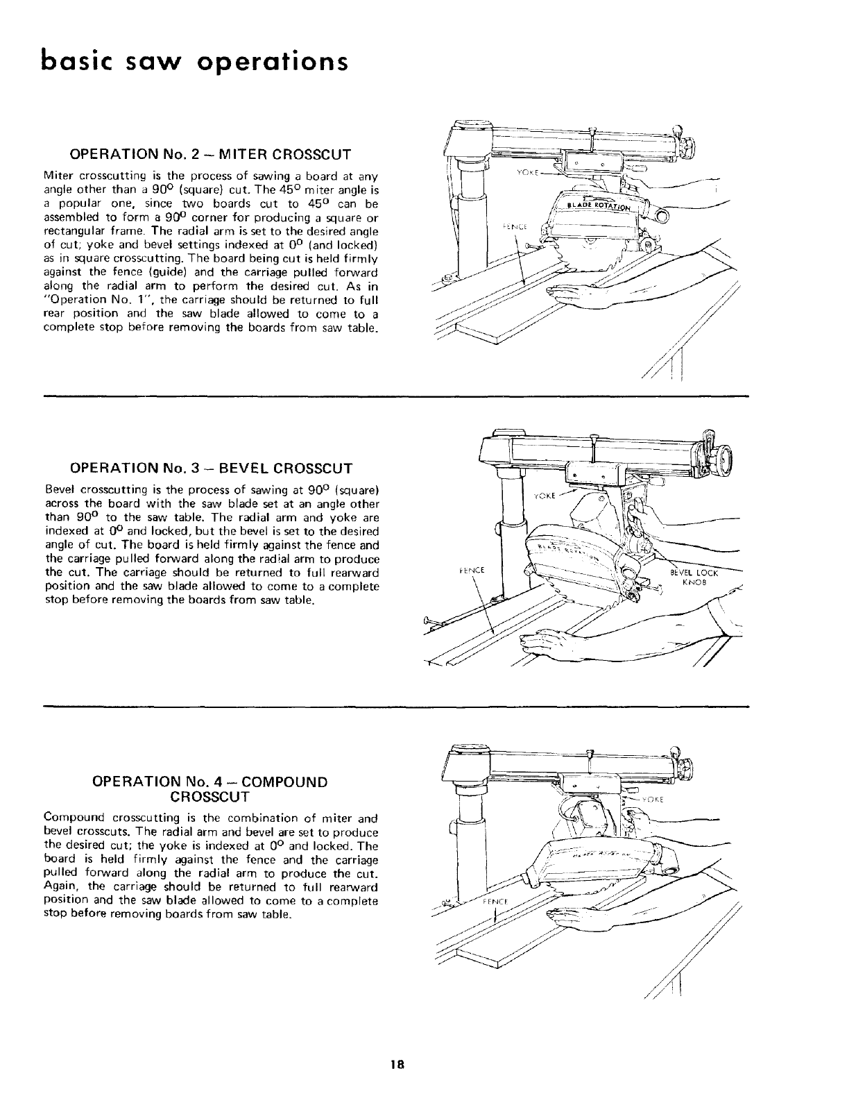
OPERATION No. 2 -MITER CROSSCUT
Miter crosscutting is the process of sawing a board at any
angle other than a 90 ° (square) cut. The 45 ° miter angle is
a popular one, since two boards cut to 45 ° can be
assembled to form a 90 ° corner for producing a square or
rectangular frame The radial arm is set to the desired angle
of cut; yoke and bevel settings indexed at 0 ° (and locked)
as in square crosscutting. The board being cut is held firmly
against the fence (guide) and the carriage pulled forward
along the radial arm to perform the desired cut. As in
"Operation No. 1", the carriage should be returned to full
rear position and the saw blade allowed to come to a
complete stop before removing the boards from saw table.
//
OPERATION No. 3 -- BEVEL CROSSCUT
Bevel crosscutting is the process of sawing at 90 ° (square)
across the board with the saw blade set at an angle other
than 90 ° to the saw table. The radial arm and yoke are
indexed at 0 ° and locked, but the bevel is set to the desired
angle of cut. The board is held firmly against the fence and
the carriage pulled forward along the radial arm to produce
the cut. The carriage should be returned to full rearward
position and the saw blade allowed to come to a complete
stop before removing the boards from saw table.
OPERATION No. 4 -- COMPOUND
CROSSCUT
Compound crosscutting is the combination of miter and
bevel crosscuts. The radial arm and bevel are set to produce
the desired cut; the yoke is indexed at 0 ° and locked. The
board is held firmly against the fence and the carriage
pulled forward along the radial arm to produce the cut.
Again, the carriage should be returned to full rearward
position and the saw blade allowed to come to a complete
stop before removing boards from saw table.
18
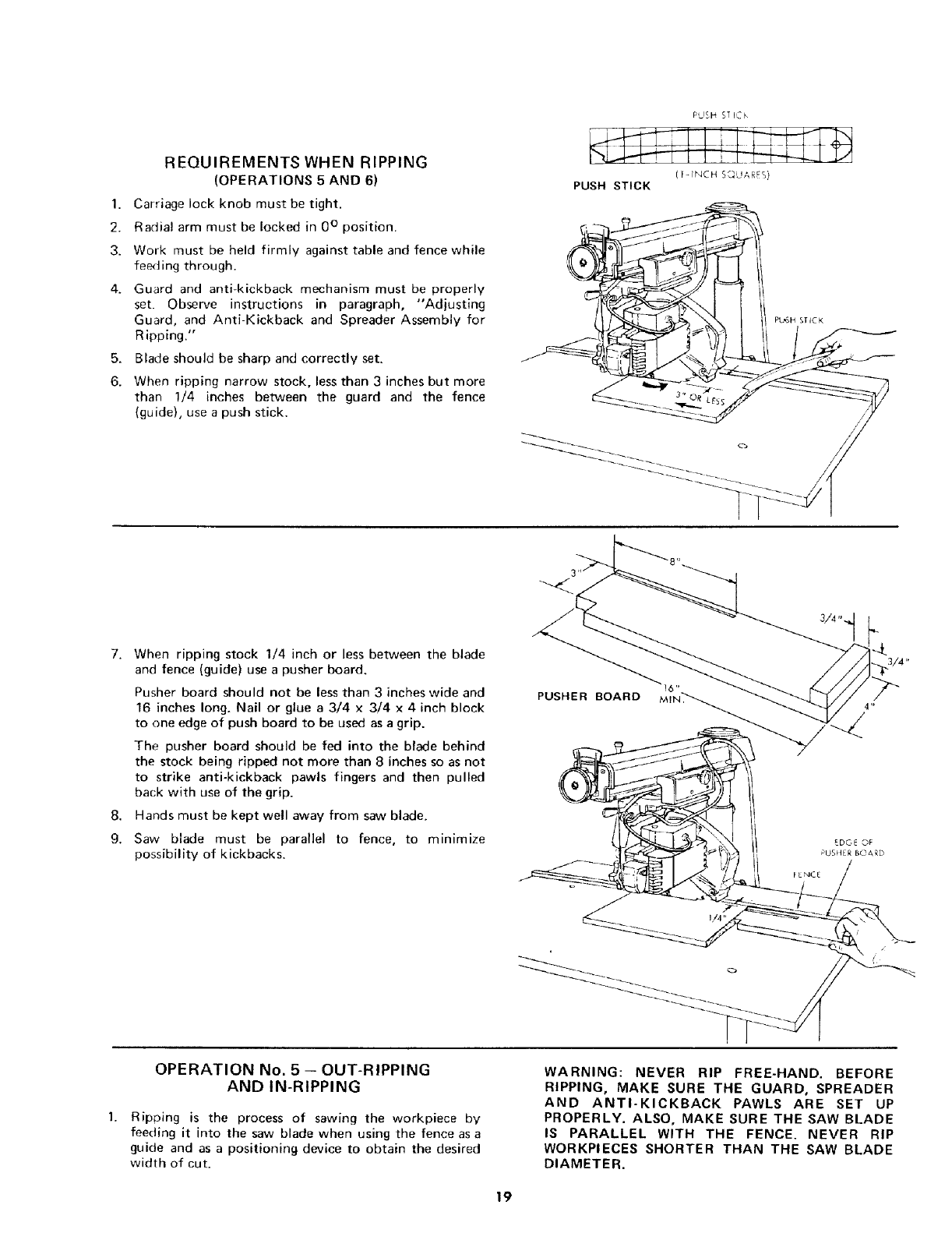
REQUIREMENTS WHEN RIPPING
(OPERATIONS 5 AND 6)
1. Carriage lock knob must be tight.
2. Radial arm must be locked in 0 ° position.
3. Work must be held firmly against table and fence while
feeding through.
4. Guard and anti-kickback mechanism must be properly
set. Observe instructions in paragraph, "Adjusting
Guard, and Anti Kickback and Spreader Assembly for
Ripping.'"
5. Blade should be sharp and correctly set.
6. When ripping narrow stock, less than 3 inches but more
than 1/4 inches between the guard and the fence
(guide), use a push stick.
F:'JSH STICh
(I_FNCH SL_L!ARES)
PUSH STICK
PL_SH STICK
8,
9.
When ripping stock 1/4 inch or less between the blade
and fence (guide) use a pusher board.
Pusher board should not be less than 3 inches wide and
16 inches long. Nail or glue a 3/4 x 3/4 x 4 inch block
to one edge of push board to be used as a grip.
The pusher board should be fed into the blade behind
the stock being ripped not more than 8 inches so as not
to strike anti-kickback pawls fingers and then pulled
back with use of the grip.
Hands must be kept well away from saw blade,
Saw blade must be parallel to fence, to mimmize
possibility of kickbacks.
PUSHER BOARD
3/4".
EDGE OF
PUSftER BOARD
OPERATION No. 5 - OUT-RIPPING
AND IN-RIPPING
Ripping is the process of sawing the workpiece by
feeding it into the saw blade when using the fence as a
guide and as a positioning device to obtain the desired
width of cut.
WARNING: NEVER RIP FREE-HAND. BEFORE
RIPPING, MAKE SURE THE GUARD, SPREADER
AND ANTI-KICKBACK PAWLS ARE SET UP
PROPERLY. ALSO, MAKE SURE THE SAW BLADE
IS PARALLEL WITH THE FENCE. NEVER RIP
WORKPIECES SHORTER THAN THE SAW BLADE
DIAMETER.
19
basic saw operations
2.
3.
4.
Since the work is pushed along the fence, it must have a
reasonably straight edge in order to make sliding
contact with the fence. Also, the work must make solid
contact with the table, so that it will not wobble.
Provide astraight edge, even if this means temporary
nailing of an auxiliary straight-edged board to the work.
If the workpiece is warped, turn the hollow side down.
Always use the saw guard and make sure the spreader is
correctly aligned with the saw kerf. Wood cut with the
grain tends to spring the kerf closed and bind the blade
and a kickback could occur.
Stand a little to one side of center to avoid being
sprayed with sawdust and to be clear of work in case of
kickback.
5. When ripping short or narrow work, always use a push
stick applied to the section of the workpiece between
the blade and fence ... push the work past the blade
so it is clear of the blade. This procedure will minimize
the possibility of kickbacks.
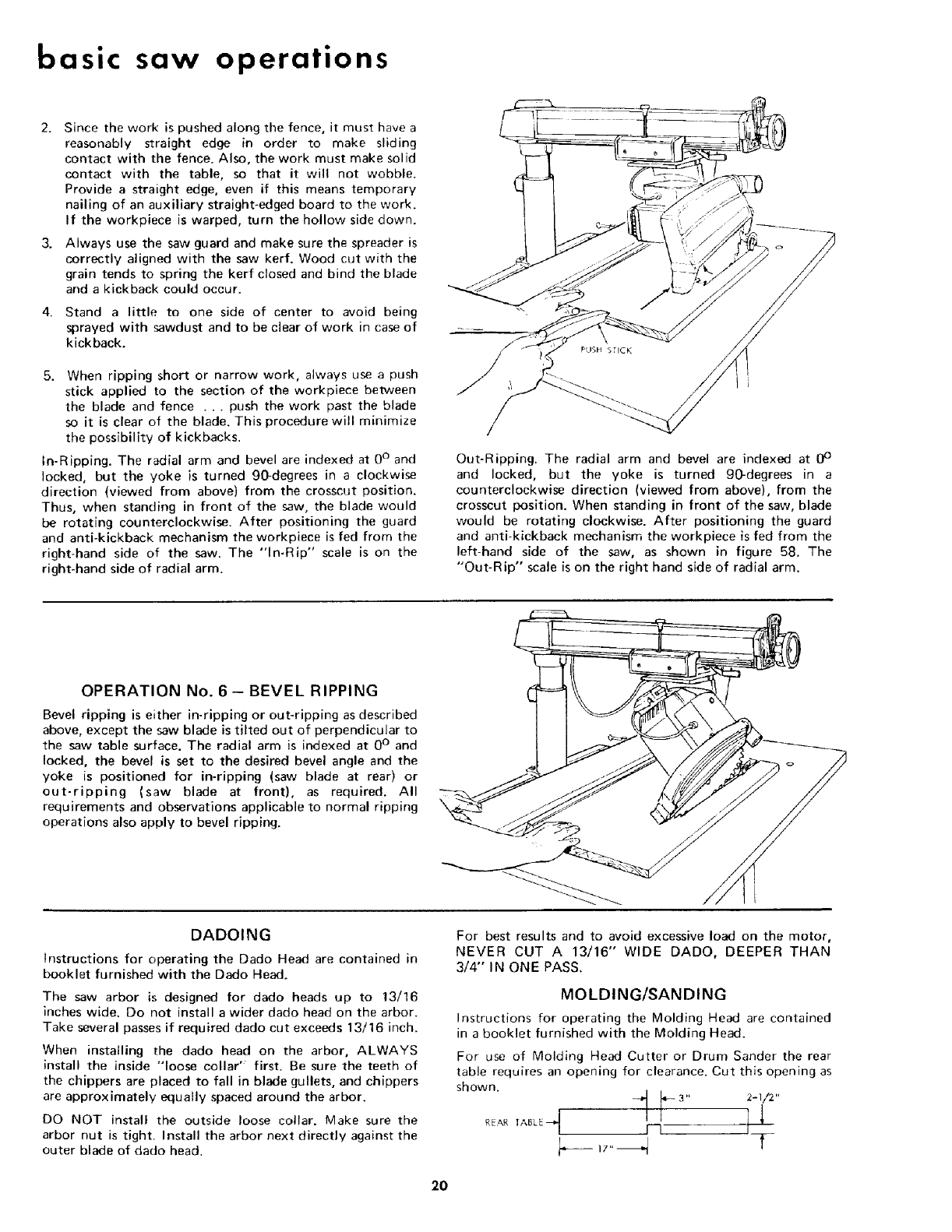
In-Ripping. The radial arm and bevel are indexed at 0 ° and
locked, but the yoke is turned 90-degrees in a clockwise
direction (viewed from above) from the crosscut position.
Thus, when standing in front of the saw, the blade would
be rotating counterclockwise. After positioning the guard
and anti-kickback mechanism the workpiece is fed from the
right-hand side of the saw. The "In-Rip" scale is on the
right-hand side of radial arm.
Out-Ripping. The radial arm and bevel are indexed at 0 °
and locked, but the yoke is turned 90-degrees in a
counterclockwise direction (viewed from above), from the
crosscut position. When standing in front of the saw, blade
would be rotating clockwise. After positioning the guard
and anti-kickback mechanism the workpiece is fed from the
left-hand side of the saw, as shown in figure 58. The
"Out-Rip" scale is on the right hand side of radial arm.
OPERATION No. 6- BEVEL RIPPING
Bevel ripping is either in-ripping or out-ripping as described
above, except the saw blade is tilted out of perpendicular to
the saw table surface. The radial arm is indexed at 0 ° and
locked, the bevel is set to the desired bevel angle and the
yoke is positioned for in-ripping (saw blade at rear) or
out-ripping (saw blade at front), as required. All
requirements and observations applicable to normal ripping
operations also apply to bevel ripping.
DADOING
Instructions for operating the Dado Head are contained in
booklet furnished with the Dado Head.
The saw arbor is designed for dado heads up to 13/16
inches wide. Do not install a wider dado head on the arbor.
Take several passes if required dado cut exceeds 13/16 inch.
When installing the dado head on the arbor, ALWAYS
install the inside "loose collar" first. Be sure the teeth of
the chippers are placed to fall in blade gullets, and chippers
are approximately equally spaced around the arbor.
DO NOT install the outside loose collar. Make sure the
arbor nut is tight. Install the arbor next directly against the
outer blade of dado head.
For best results and to avoid excessive load on the motor,
NEVER CUT A 13/16" WIDE DADO0 DEEPER THAN
3/4" IN ONE PASS.
MOLDING/SANDING
Ins[ructions for operating the Molding Head are contained
in a booklet furnished with the Molding Head.
For use of Molding Head Cutter or Drum Sander the rear
table requires an opening for clearance. Cut this opening as
shown. ,, 2-1/2,,
2O
electrical connections
POWER SUPPLY
1. Motor Specifications
The A-C motor used in this saw is a capacitor-start,
non-reversible type having the following specifications:
Voltage ............................ 120
Amperes ............................ 12.5
Hertz (cycles) ............................ 60
Phase ................................ Single
RPM ................................. 3450
Rotation as viewed
from saw blade end ................. Clockwise
CAUTION: YOUR SAW IS WIRED FOR 120V
OPERATION. CONNECT TO A 120V, 15-AMP.
BRANCH CIRCUIT AND USE A 15-AMP.,
TIME-DELAY FUSE OR CIRCUIT BREAKER.
WARNING: DO NOT PERMIT FINGERS TO TOUCH
THE TERMINALS OF PLUGS WHEN INSTALLING
OR REMOVING THE PLUG TO OR FROM THE
OUTLET.
WARNING: IF NOT PROPERLY GROUNDED THIS
POWER TOOL CAN INCUR THE POTENTIAL
HAZARD OF ELECTRICAL SHOCK,
PARTICULARLY WHEN USED IN DAMP
LOCATIONS, IN PROXIMITY TO PLUMBING, OR
OUT OF DOORS. IF AN ELECTRICAL SHOCK
OCCURS THERE IS THE POTENTIAL OF A
SECONDARY HAZARD SUCH AS YOUR HANDS
CONTACTING THE SAW BLADE.
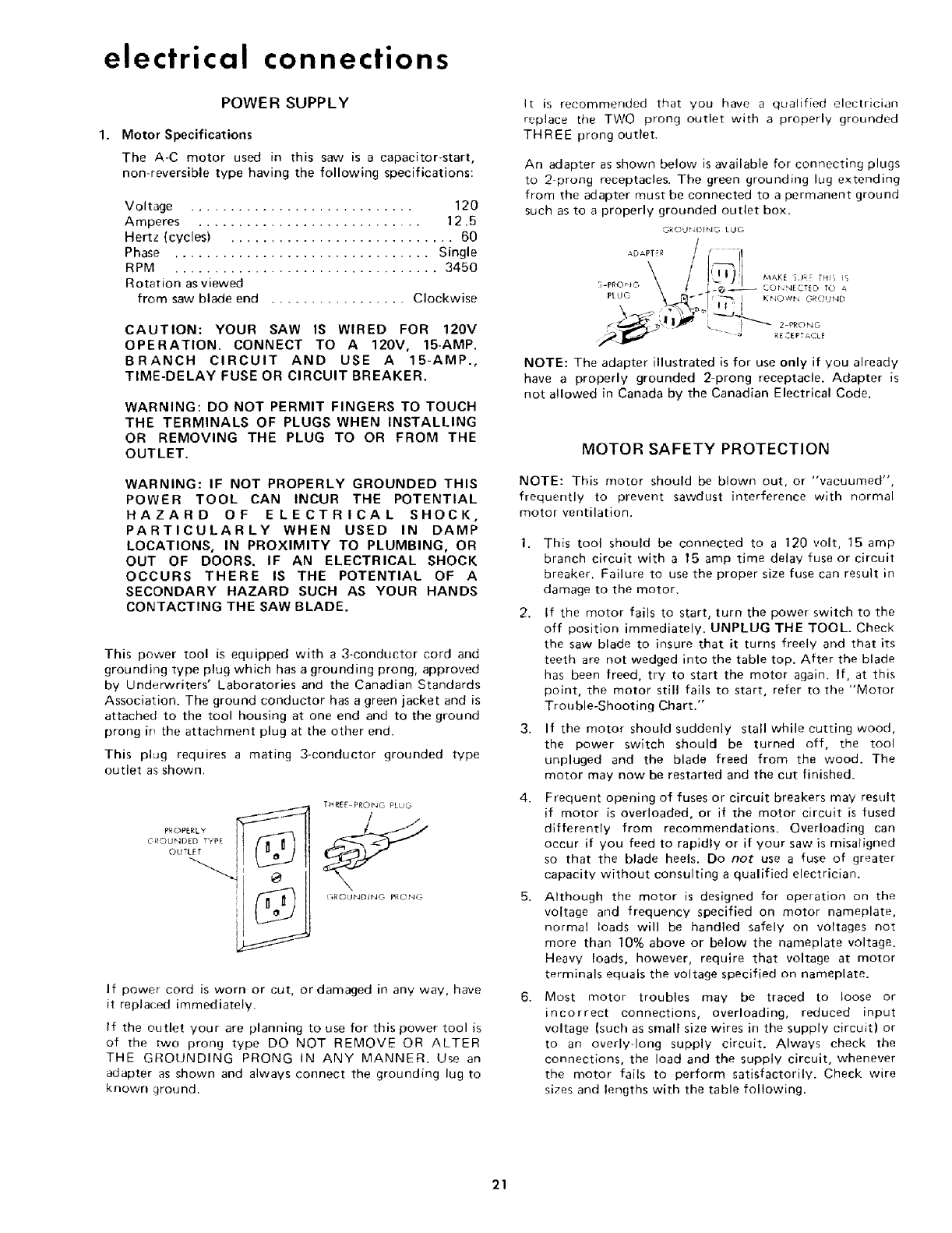
This power tool is equipped with a 3-conductor cord and
grounding type plug which has a grounding prong, approved
by Underwriters' Laboratories and the Canadian Standards
Association. The ground conductor has a green jacket and is
attached to the tool housing at one end and to the ground
prong irt the attachment plug at the other end.
This plug requires a mating 3-conductor grounded type
outlet as shown.
OUTLET !
THREE PRONG PLUG
GROUNDING PRONG
If power cord is worn or cut, or damaged in any way, have
it replaced immediately.
If the outlet your are planning to use for this power tool is
of the two prong type DO NOT REMOVE OR ALTER
THE GROUNDING PRONG IN ANY MANNER. Use an
adapter as shown and always connect the groLmding lug to
known ground.
It is recommended that you have a qualified electrician
replace the TWO prong outlet with a properly grounded
THREE prong outlet.
An adapter as shown below is available for connecting plugs
to 2-prong receptacles. The green grounding lug extending
from the adapter must be connected to a permanent ground
such as to a properly grounded outlet box.
O_OU_D_NGLUG
PlUG \ _._ _/t _'_ KNOW'b GROUND
NOTE: The adapter illustrated is for use only if you already
have a properly grounded 2-prong receptacle. Adapter is
not allowed in Canada by the Canadian Electrical Code.
MOTOR SAFETY PROTECTION
NOTE: This motor should be blown out, or "vacuumed",
frequently to prevent sawdust interference with normal
motor ventilation.
1. This tool should be connected to a 120 volt, 15 amp
branch circuit with a 15 amp time delay fuse or circuit
breaker. Failure to use the proper size fuse can result in
damage to the motor.
2. If the motor fails to start, turn the power switch to the
off position immediately. UNPLUG THE TOOL. Check
the saw blade to insure that it turns freely and that its
teeth are not wedged into the table top. After the blade
has been freed, try to start the motor again. If, at this
point, the motor still fails to start, refer to the "Motor
Trouble-Shooting Chart."
3. If the motor should suddenly stall while cutting wood,
the power switch should be turned off, the tool
unpluged and the blade freed from the wood. The
motor may now be restarted and the cut finished.
4. Frequent opening of fuses or circuit breakers may result
if motor is overloaded, or if the motor circuit is fused
differently from recommendations. Overloading can
occur if you feed to rapidly or if your saw is misatigned
so that the blade heels. Do not use a fuse of greater
capacity without consulting a qualified electrician.
5. Although the motor is designed for operation on the
voltage and frequency specified on motor nameplate,
normal loads will be handled safely on voltages not
more than 10% above or below the nameplate voltage.
Heavy loads, however, require that voltage at motor
terminals equals the voltage specified on nameplate.
6. Most motor troubles may be traced to loose or
incorrect connections, overloading, reduced input
voltage (such as small size wires in the supply circuit) or
to an overly-long supply circuit. Always check the
connections, the load and the supply circuit, whenever
the motor fails to perform satisfactorily. Check wire
sizes and lengths with the table following.
21
Wire Size Required
Length of the (American Wire Gauge Number)
Conductor 120 Volt Line
WIRE SIZES
The use of any extension cord will cause some loss of
power. To keep this to aminimum and to prevent
over-heating and motor burn-out, use the table below to
determine the m_nimum wire size {A.W.G.) extension cord.
Use only 3 wire extension cords which have 3 prong
grounding type plugs and 3-pole receptacles which accept
the tools plug.
Up to 100 feet
100 feet to 200 feet
200 feet to 400 feet
No. 12
No. 8
No. 6
NOTE: For circuits of greater length, the wire size must be
increased proportionately in order to deliver ample voltage
to the saw motor.
trouble-shooting
WARNING: REMOVE POWER CORD FROM POWER
SOURCE BEFORE TROUBLE SHOOTING.
Even' though the finest materials and precision
workmanship have been incorporated into your Craftsman
saw, it is reasonable to expect some wear after long periods
of use. Sooner or later, the metal to metal parts must wear
and will need take-up. Every metal to metal part on your
Craftsman saw can be taken up. In this way, the machine
can always be kept accurate and just as important, rigid.
The usual operating "troubles" are listed in the following
paragraphs with the necessary corrections listed.
LOOSENESS OF COLUMN TUBE IN COLUMN
SUPPORT - ELEVATION CRANK OPERATES
ROUGHLY OR CHATTERS WHEN ROTATED.
Refer to Step two in Alignment Procedure Section.
Check for looseness (movement) of column tube in
column support.
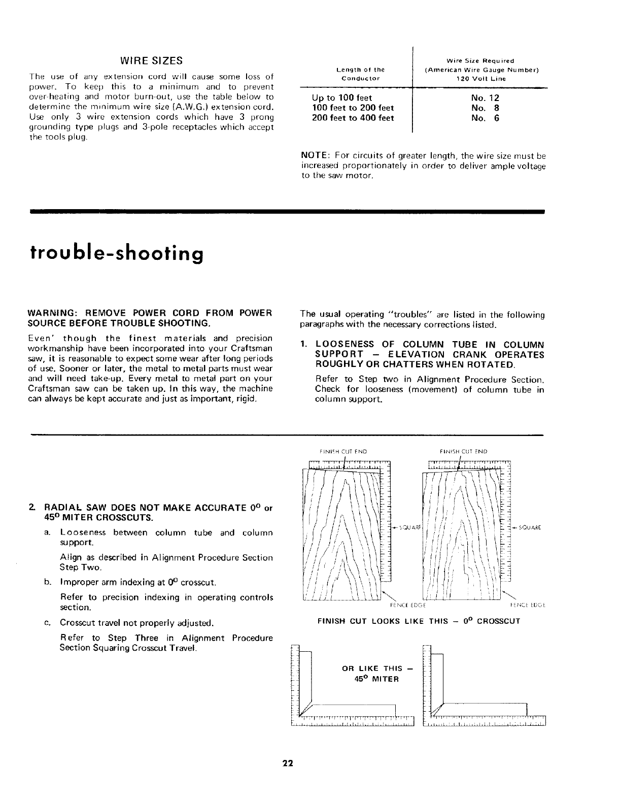
RADIAL SAW DOES NOT MAKE ACCURATE 0° or
45° MITER CROSSCUTS.
a. Looseness between column tube and column
support.
Align as described in Alignment Procedure Section
Step Two.
Improper arm indexing at 0 ° crosscut.
Refer to precision indexing in operating controls
section.
c. Crosscut travel not properly adjusted.
Refer to Step Three in Alignment Procedure
Section Squaring Crosscut Travel.
FINIEH CUT END FINtSH CU _ END
FENCE EDGE FEt,_CE EDOE
FINISH CUT LOOKS LIKE THIS -- 00 CROSSCUT
OR LIKE THIS --
,45° MITER _ iii I i iI i
22
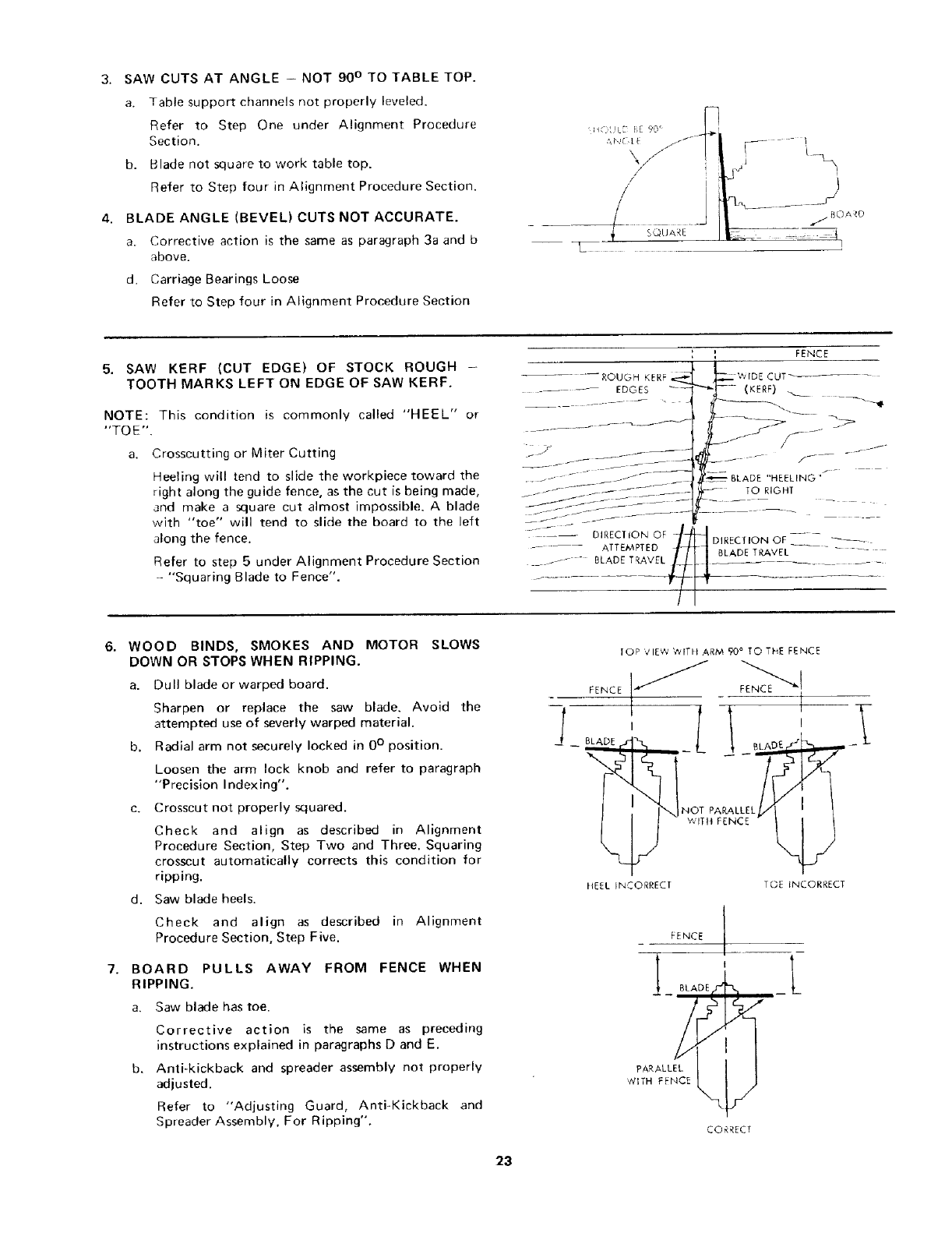
3. SAW CUTS AT ANGLE - NOT 90 ° TO TABLE TOP.
a. Table support channels not properly leveled.
Refer to Step One under Alignment Procedure
Section.
b. Blade not square to work table top.
Refer to Step four in Alignment Procedure Section.
4. BLADE ANGLE (BEVEL) CUTS NOT ACCURATE.
a. Corrective action is the same as paragraph 3a and b
above.
d. Carriage Bearings Loose
Refer to Step four in Alignment Procedure Section
i(::!L[ [,E 90 _ L_
T
\///
/
/
SQtJARE
S,_J
J
_BOARD
I
5. SAW KERF (CUT EDGE) OF STOCK ROUGH -
TOOTH MARKS LEFT ON EDGE OF SAW KERF.
NOTE: This condition is commonly called "HEEL" or
"TO E".
a, Crosscutting or Miter Cutting
Heeling will tend to slide the workpiece toward the
right along the guide fence, as the cut is being made,
and make a square cut almost impossible. A blade
with "toe" will tend to slide the board to the left
along the fence.
Refer to step 5 under Alignment Procedure Section
-- "Squaring Blade to Fence".
' ' FENCE
, *
(KERF)
"HEELING '
TO RIGHT
DIRECTION OF -- _
BLADE TRAVEL
6, WOOD BINDS, SMOKES AND MOTOR SLOWS
DOWN OR STOPS WHEN RIPPING.
a. Dull blade or warped board.
Sharpen or replace the saw blade. Avoid the
attempted use of severly warped material.
b. Radial arm not securely locked in 0 ° position.
Loosen the arm lock knob and refer to paragraph
"Precision Indexing".
Crosscut not properly squared.
Check and align as described in Alignment
Procedure Section, Step Two and Three. Squaring
crosscut automatically corrects this condition for
ripping.
d. Saw blade heels.
Check and align as described in Alignment
Procedure Section, Step Five.
BOARD PULLS AWAY FROM FENCE WHEN
RIPPING.
a. Saw blade has toe.
Corrective action is the same as preceding
instructions explained in paragraphs D and E.
b, Anti-kickback and spreader assembly not properly
adjusted.
Refer to "Adjusting Guard, Anti-Kickback and
Spreader Assembly, For Ripping".
TOP VIEW WITIt ARM 90 ° TO THE FENCE
_!
HEEL INCORRECT TOE INCORRECT
FENCE i
-- BLA __ L
/
PARALLEL
WITH FENCE
CORRECT
23
trouble-shooting
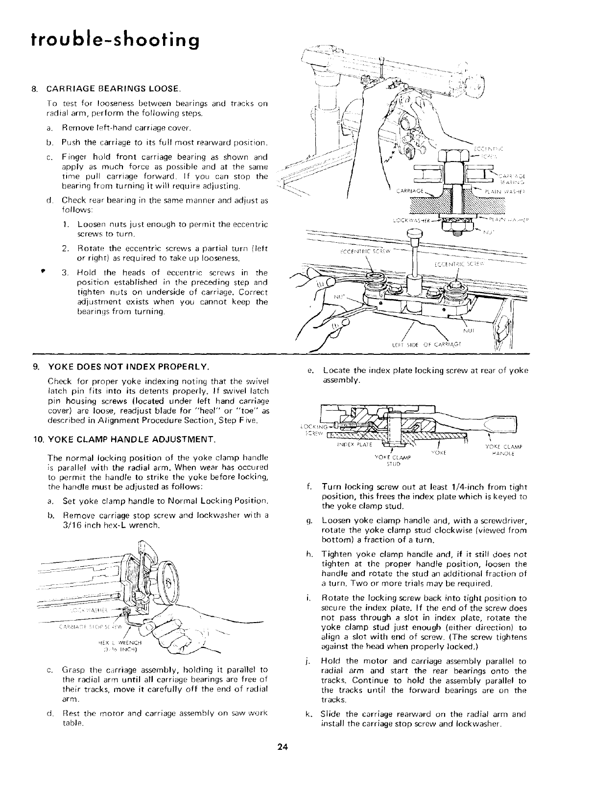
CARRIAGE BEARINGS LOOSE.
To test for looseness between bearings and tracks on
radial arm, perform the following steps,
a. Remove left-hand carriage cover.
b, Push the carriage to its full most rearward position.
c. Finger hold front carriage bearing as shown and
apply as much force as possible and at the same
time pull carriage forward. If you can stop the
bearing from turning it will require adjusting.
d. Check rear bearing in the same manner and adjust as
follows:
1, Loosen nuts just enough to permit the eccentric
screws to turn.
2. Rotate the eccentric screws a partial turn lleft
or right) as required to take up looseness.
3, Hold the heads of eccentric screws in the
position established in the preceding step and
tighten nuts on underside of carriage. Correct
adjustment exists when you cannot keep the
bearings from turning.
NU;
LEF1 SIDE OF CARRIAG
9. YOKE DOES NOT INDEX PROPERLY.
Check for proper yoke indexing noting that the swivel
latch pin fits into its detents properly, If swivel latch
pin housing screws (located under left hand carriage
cover) are loose, readjust blade for "heel" or "toe" as
described in Alignment Procedure Section, Step Five.
10. YOKE CLAMP HANDLE ADJUSTMENT.
The normal locking position of the yoke clamp handle
is parallel with the radial arm. When wear has occured
to permit the handle to strike the yoke before locking,
the handle must be adjusted as follows:
a. Set yoke clamp handle to Normal Locking Position.
b. Remove carriage stop screw and Iockwasher with a
3/16 inch hex-L wrench.
q,rX ¢lR Er'4Ct{
3_INCH) L ,. / '_ '
C.
d.
Grasp the carriage assembly, holding it parallel to
the radial arm until all carriage bearings are free of
their tracks, move it carefully off the end of radial
arm.
Rest the motor and carriage assembly on saw work
table.
e. Locate the index plate locking screw at rear of yoke
assembly.
L 'OC x tN_ M
CR_w
_1 voK_ HAbJOL_
YO_E CLAMP
STUD
g,
h,
k_
Turn locking screw out at least 1/4-inch from tight
position, this frees the index plate which is keyed to
the yoke clamp stud.
Loosen yoke clamp handle and, with a screwdriver,
rotate the yoke clamp stud clockwise (viewed from
bottom) afraction of a turn.
Tighten yoke clamp handle and, if it still does not
tighten at the proper handle position, loosen the
handle and rotate the stud an additional fraction of
a turn. Two or more trials may be required.
Rotate the locking screw back into tight position to
secure the index plate. If the end of the screw does
not pass through a slot in index plate, rotate the
yoke clamp stud just enough (either direction) to
align a slot with end of screw. (The screw tightens
against the head when properly locked,)
Hold the motor and carriage assembly parallel to
radial arm and start the rear bearings onto the
tracks. Continue to hold the assembly parallel to
the tracks until the forward bearings are on the
tracks.
Slide the carriage rearward on the radial arm and
install the carriage stop screw and Iockwasher,
24
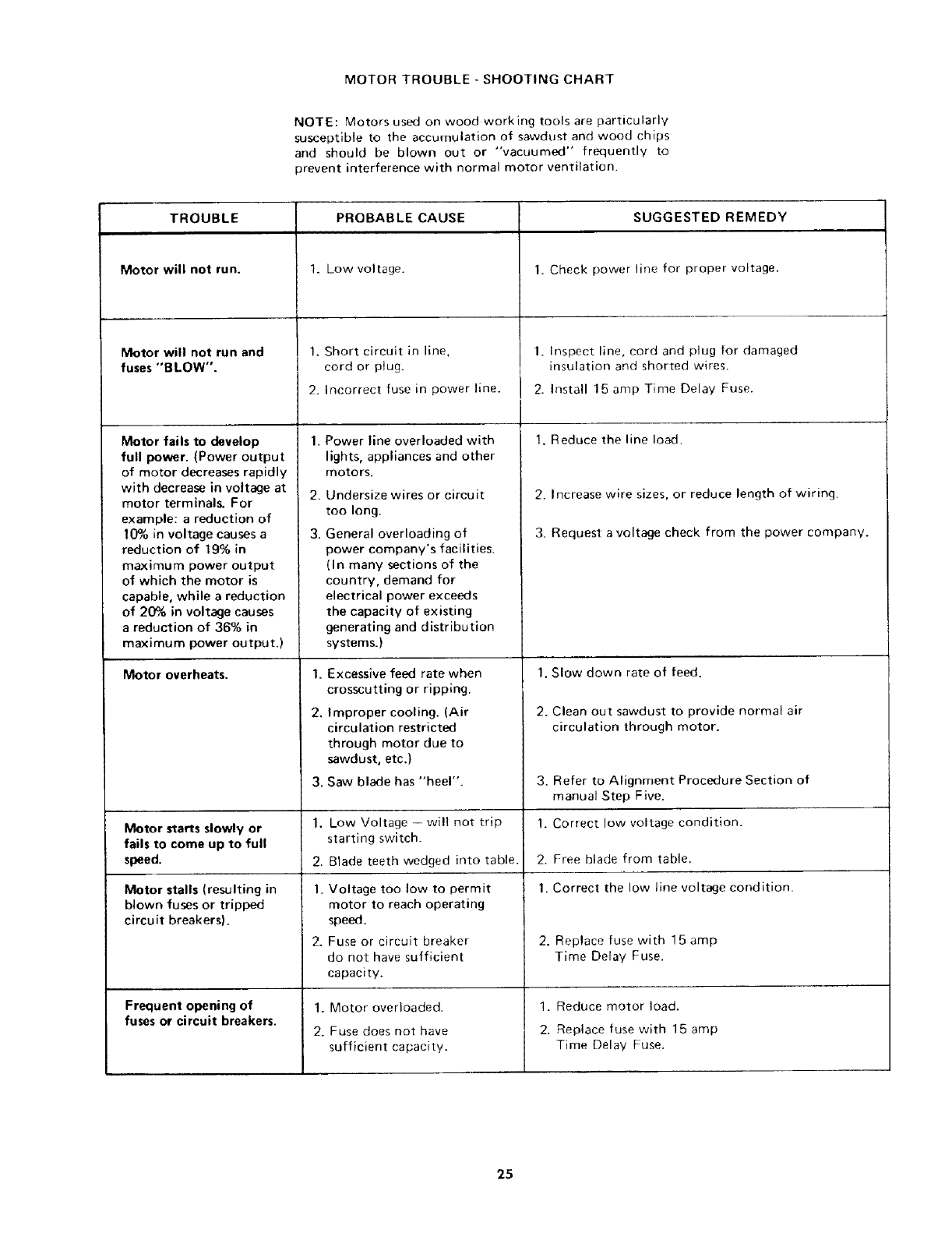
MOTOR TROUBLE -SHOOTING CHART
NOTE: Motors used on wood working tools are particularly
susceptible to the accumulation of sawdust and wood chips
and should be blown out or "vacuumed" frequently to
prevent interference with normal motor ventilation.
TROUBLE
Motor will not run.
Motor will not run and
fuses "BLOW".
Motor fails to develop
full power. (Power output
of motor decreases rapidly
with decrease in voltage at
motor terminals. For
example: a reduction of
10% in voltage causes a
reduction of 19% in
maximum power output
of which the motor is
capable, while a reduction
of 20% in voltage causes
a reduction of 36% in
maximum power output.)
Motor overheats.
Motor starts slowly or
fails to come up to full
speed.
Motor stalls (resulting in
blown fuses or tripped
circuit breakers).
Frequent opening of
fuses or circuit breakers.
PROBABLE CAUSE
1. Low voltage.
1. Short circuit in line,
cord or plug.
2. Incorrect fuse in power line.
1. Power line overloaded with
lights, appliances and other
motors.
2. Undersize wires or circuit
too long.
3. General overloading of
power company's facil i ties.
(In many sections of the
country, demand for
electrical power exceeds
the capacity of existing
generating and distribution
systems.)
1. Excessive feed rate when
crosscutting or ripping,
2, Improper cooling. (Air
circulation restricted
through motor clue to
sawdust, etc.)
3. Saw blade has "heel".
1. Low Voltage -- will not trip
starting switch.
2. Blade teeth wedged into table.
1. Voltage too low to permit
motor to reach operating
speed.
2. Fuse or circuit breaker
do not have sufficient
capacity.
1. Motor overloaded.
2. Fuse does not have
sufficient capacity.
SUGGESTED REMEDY
1. Check power line for proper voltage.
1. Inspect line, cord and plug for damaged
insulation and shorted wires,
2. Install 15 amp Time Delay Fuse.
1. Reduce the line load.
2. Increase wire sizes, or reduce length of wiring.
3. Request a voltage check from the power company.
1. Slow down rate of feed.
2. Clean out sawdust to provide normal air
circulation through motor.
3. Refer to Alignment Procedure Section of
manual Step Five.
1. Correct low voltage condition.
2. Free blade from table.
1. Correct the low line voltage condition.
2. Replace fuse with 15 amp
Time Delay Fuse.
1. Reduce motor load.
2. Replace fuse with 15 amp
Time Delay Fuse.
25
maintenance and lubrication
MAINTENANCE
WARNING: FOR YOUR OWN SAFETY, TURN SWITCH
"OFF" AND REMOVE PLUG FROM POWER SOURCE
OUTLET BEFORE MAINTAINING OR LUBRICATING
YOUR SAW.
When you receive your new Craftsman radial saw, it
requires no lubrication. The radial saw has been partially
aligned and all bearings are lubricated and sealed for life. In
time, however, in order to keep your saw in perfect
working order and accurate, it will be necessary to lubricate
and realign. In fact, your radial saw needs more of a
cleaning than a lubrication.
Make sure the teeth of the ANTI-KICKBACK pawls are
atways sharp. Reface if not sharp.
LUBRICATION
Your saw is precision built and should be kept clean and
properly lubricated. Before describing the various points
which may periodically require lubrication, IT IS MORE
IMPORTANT TO FIRST MENTION THE VARIOUS
POINTS WHICH SHOULD NOT BE LUBRICATED.
NO LUBRICATION REQUIRED
Do not lubricate carriage ball bearings or motor bearings as
these are sealed ball bearings and require no added
lubrication.
Do not lubricate between radial arm cap and radial arm.
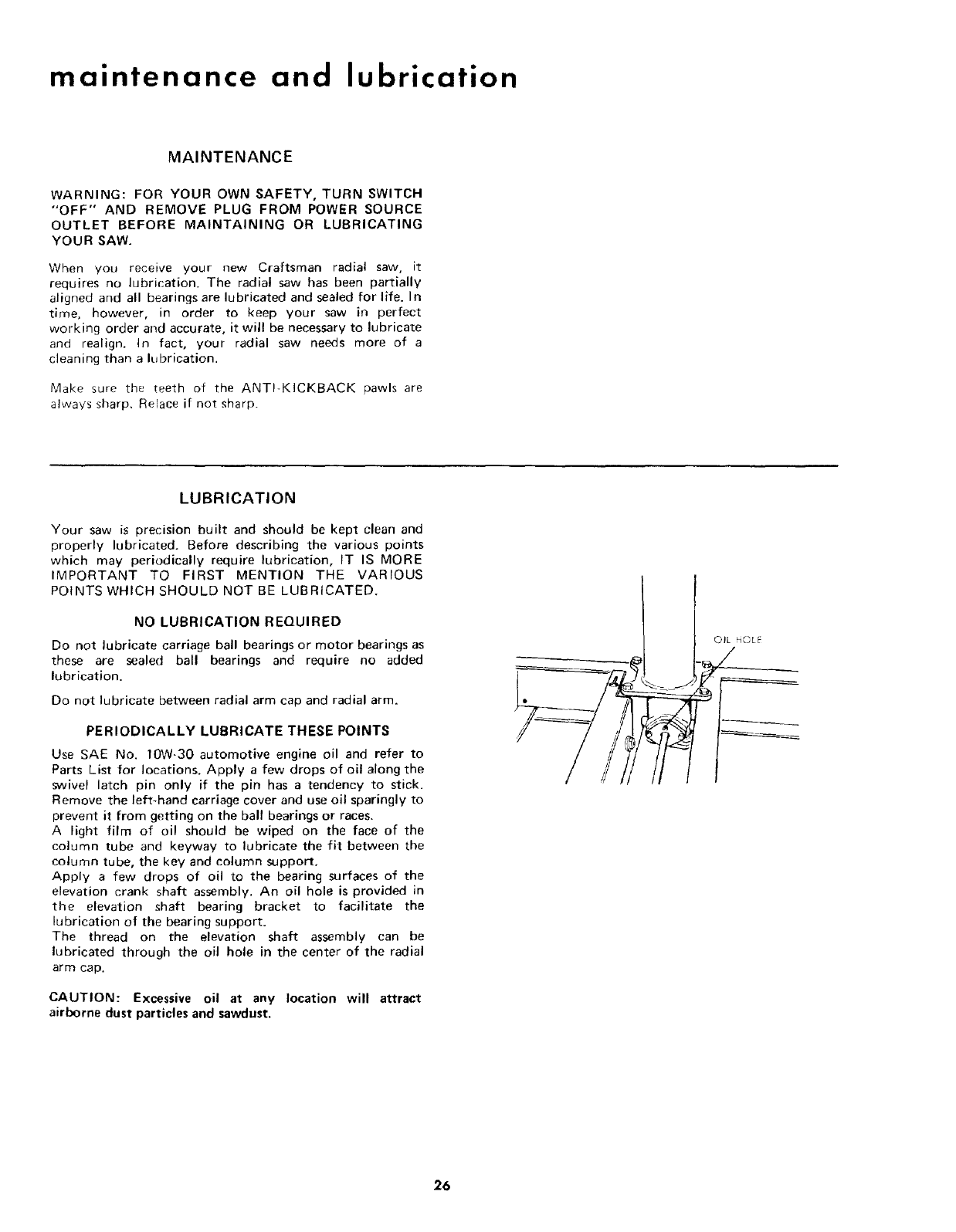
PERIODICALLY LUBRICATE THESE POINTS
Use SAE No. 10W-30 automotive engine oil and refer to
Parts List for locations. Apply a few drops of oil along the
swivel latch pin only if the pin has a tendency to stick.
Remove the left-hand carriage cover and use oil sparingly to
prevent it from getting on the ball bearings or races.
A light film of oil should be wiped on the face of the
column tube and keyway to lubricate the fit between the
column tube, the key and column support.
Apply a few drops of oil to the bearing surfaces of the
elevation crank shaft assembly. An oil hole is provided in
the elevation shaft bearing bracket to facilitate the
lubrication of the bearing support.
The thread on the elevation shaft assembly can be
lubricated through the oil hole in the center of the radial
arm cap.
CAUTION: Excessive oil at any location will attract
airborne dust particles and sawdust.
OIL HOLE
26
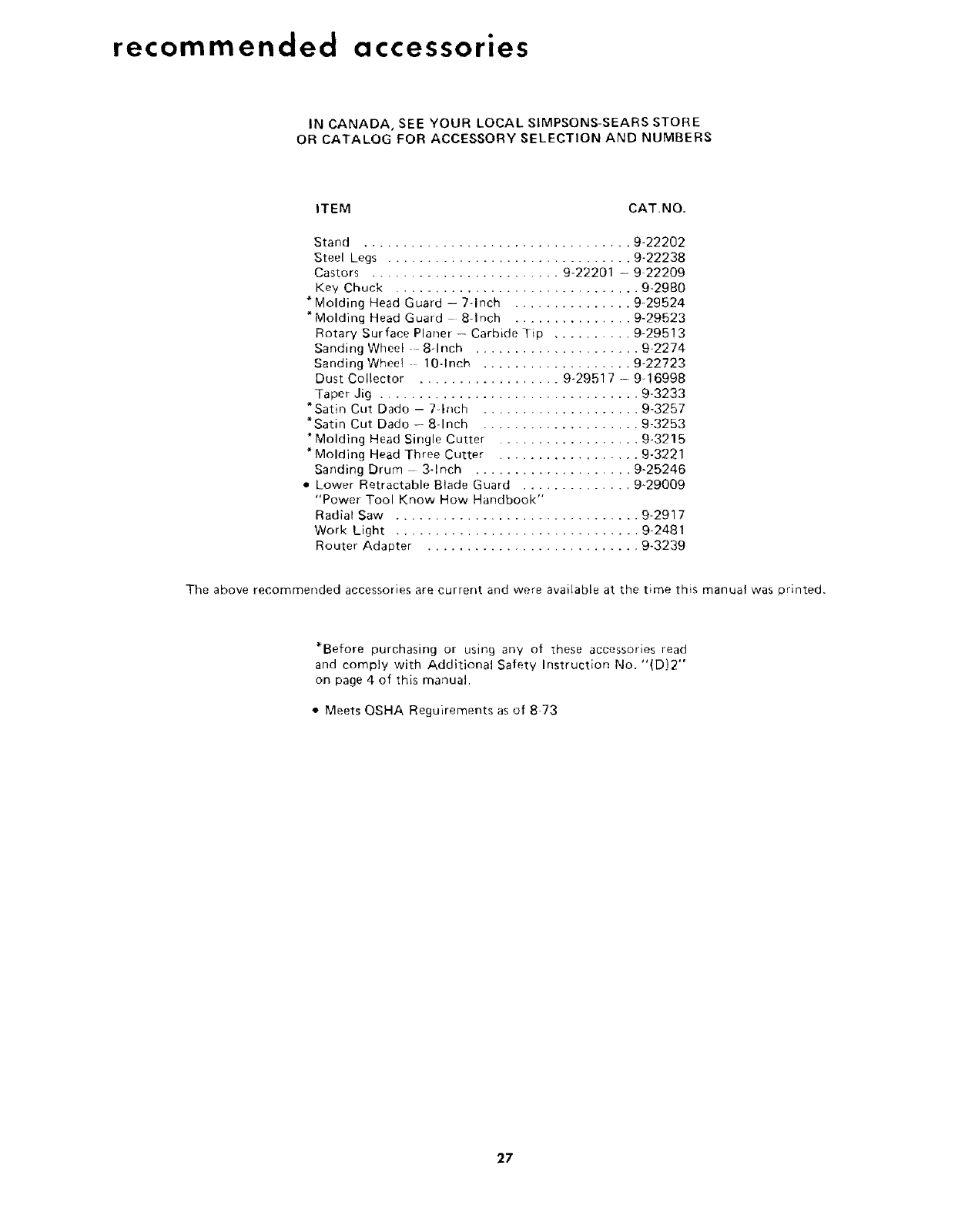
recommended accessories
IN CANADA, SEE YOUR LOCAL SIMPSONS-SEARS STORE
OR CATALOG FOR ACCESSORY SELECTION AND NUMBERS
ITEM CAT.NO.
Stand .................................. 9-22202
Steel Legs ............................... 9-22238
Castors ........................ 9-22201 - 9 22209
Key Chuck ............................... 9-2980
* Molding Head Guard - 7-Inch ............... 9-29524
*Molding Head Guard 8-Inch ............... 9-29523
Rotary Surface Planer - Carbide Tip .......... 9-29513
Sanding Wheel -- 8-Inch ..................... 9-2274
Sanding Wheel 10-Inch ................... 9-22723
Dust Collector .................. 9-29517 - 9-16998
Taper Jig ................................. 9-3233
*Satin Cut Dado - 7-Inch .................... 9-3257
*Satin Cut Dado - 8-Inch .................... 9-3253
* Molding Head Single Cutter .................. 9-3215
Molding Head Three Cutter .................. 9-3221
Sanding Drum 3-Inch .................... 9-25246
. Lower Retractable Blade Guard .............. 9-29009
"Power Tool Know How Handbook"
Radial Saw ............................... 9-2917
Work Light ............................... 9-2481
Router Adapter ........................... 9-3239
The above recommended accessories are current and were available at the time this manual was printed.
*Before purchasing or using any of these accessories read
and comply with Additional Safety Instruction No. "(D)2"
on page 4 of this manual.
• Meets QSHA Reguirements as of 8 73
27
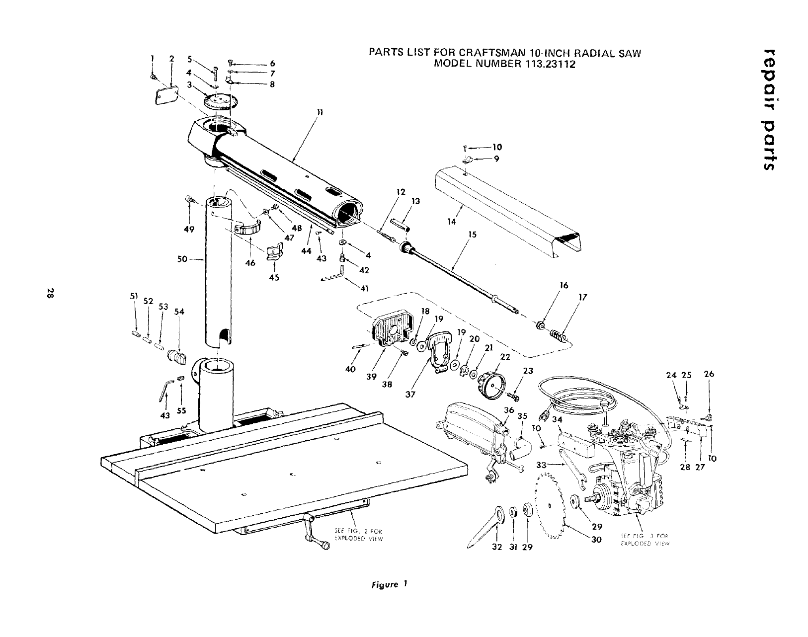
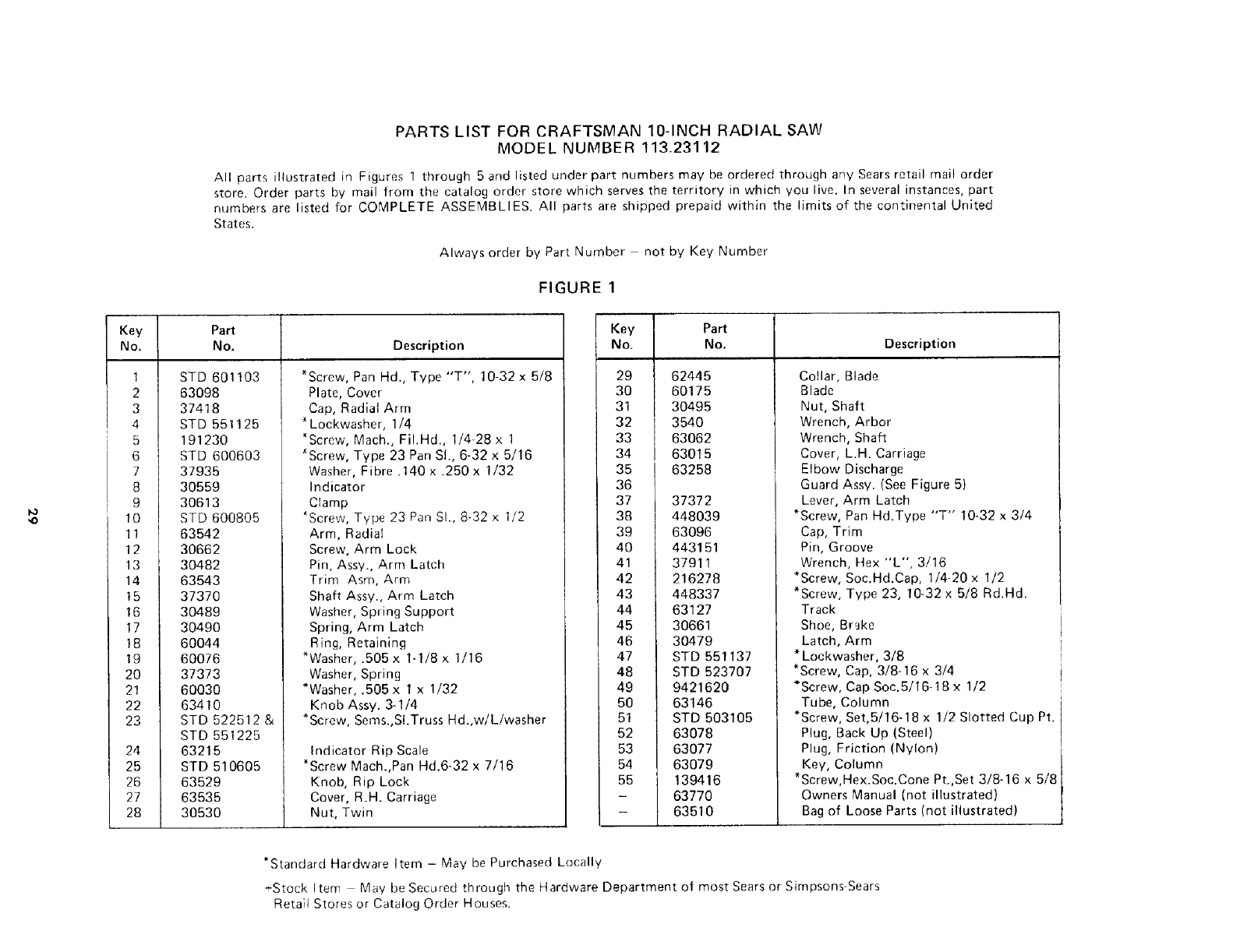
12PARTS LIST FOR CRAFTSMAN 10-INCH RADIAL SAW
MODEL NUMBER 113.23112
D
49 47
t
45
12 13
4O
16
21 " ..
23
10
32 3| 29
24 25
lO
28 27
Figure 1
PARTS LIST FOR CRAFTSMAN 10-INCH RADIAL SAW
MODEL NUMBER 113.23112
All parts illustrated in Figures 1 through 5 and listed under part numbers may be ordered through any Sears retail mail order
store. Order parts by mail from the catalog order store which serves the territory in which you live. In several instances, part
numbers are listed for COMPLETE ASSEMBLIES. All parts are shipped prepaid within the limits of the continental United
States.
Always order by Part Number not by Key Number
FIGURE 1
Key Part
No. No. Description
1
2
3
4
5
6
7
8
9
10
11
12
13
14
15
16
17
!8
19
20
21
22
23
24
25
26
27
28
STD 601103
63098
37418
STD 551125
191230
STD 600603
37935
30559
30613
STD 600805
*Screw, Pan Hd., Type "T", 10-32 x 5/8
Plate, Cover
Cap, Radial Arm
Lockwasher, 1/4
*Screw, Mach., Fi!.Hd., 1/4-28 x 1
'Screw, Type 23 Pan SI., 6-32x 5/16
Washer, Fibre .140 x .250x 1/32
Indicator
Clamp
_Screw, Type 23 Pan SI., 8-32 x 1/2
63542
30662
30482
63543
37370
30489
30490
60044
Arm, Radial
Screw, Arm Lock
Pin, Assy., Arm Latch
Trim Asm, Arm
Shaft Assy., Arm Latch
Washer, Spring Support
Spring, Arm Latch
Ring, Retaining
60076
37373
60030
63410
STD 522512 &
STD 551225
63215
STD 510605
63529
63535
30530
*Washer, .505 x 1-1/8 x 1/16
Washer, Spring
*Washer, .505x 1 x 1/32
Knob Assy. 3-1/4
*Screw, Sems.,SI.Truss Hd.,w/L/washer
Indicator Rip Scale
*Screw Mach.,Pan Hd.6-32 x 7/16
Knob, Rip Lock
Cover, R.H. Carriage
Nut, Twin
Key
No.
29
30
31
32
33
34
35
36
37
38
39
40
41
42
43
44
45
46
47
48
49
50
51
52
53
54
55
Part
No.
62445
60175
3O495
3540
63062
63015
63258
37372
448O39
63096
443151
37911
216278
448337
63127
30661
30479
STD 551137
STD 523707
Description
Collar, Blade
Blade
Nut, Shaft
Wrench, Arbor
Wrench, Shaft
Cover, L.H. Carriage
Elbow Discharge
Guard Assv. (See Figure 5)
Lever, Arm Latch
*Screw, Pan Hd.Type "T" 10-32 x 3/4
Cap, Trim
Pin, Groove
Wrench, Hex "L", 3/16
*Screw, Soc.Hd.Cap, 1/4-20 x 1/2
*Screw, Type 23, 10-32 x 5/8 Rd.Hd.
Track
Shoe, Brake
Latch, Arm
* Lockwasher, 3/8
*Screw, Cap, 3/8-16 x 3/4
9421620
63146
STD 503105
63078
63077
63079
139416
63770
6351O
*Screw, Cap Soc.5/16-18 x 1/2
Tube, Column
*Screw, Set,5/16-18 x 1/2 Slotted Cup Pt.
Plug, Back Up (Steel)
Plug, Friction (Nylon)
Key, Column
*Screw, Hex.Soc.Cone Pt.,Set 3/8-16 x 5/8
Owners Manual (not illustrated)
Bag of Loose Parts (not illustrated)
*Standard Hardware Item - May be Purchased Locally
-Stock Item May be Secured through the Hardware Department of most Sears or Simpsons-Sears
Retail Stores or Catalog Order Houses.
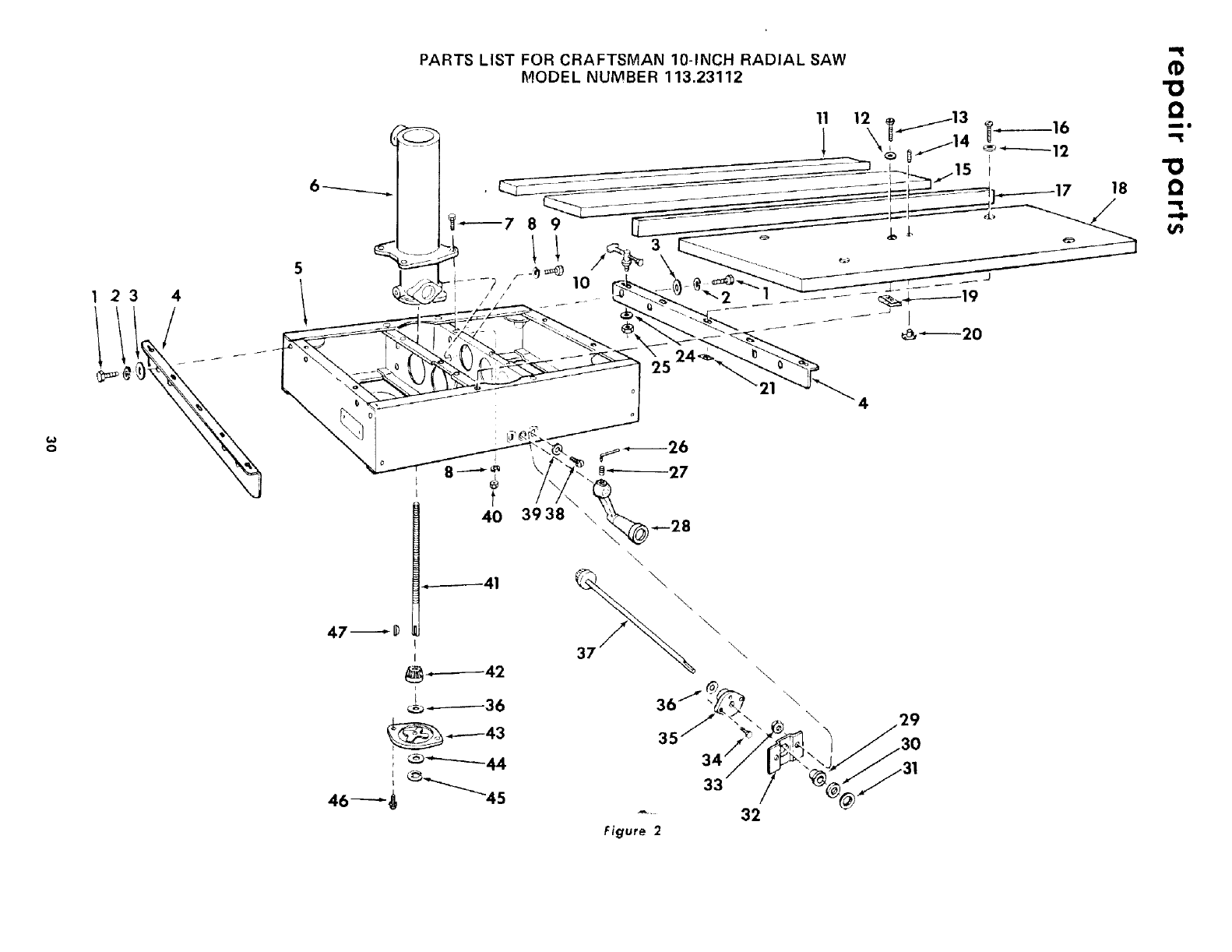
o
123 4
11t/
PARTS LIST FOR CRAFTSMAN 10-INCH RADIAL SAW
MODEL NUMBER 113.23112
5
4O
-.------41
47_
_-------42
!_._._-------36
46---_ _"_45
3938
37
"\
\\
18
==I
Q
mo
"0
0
it"
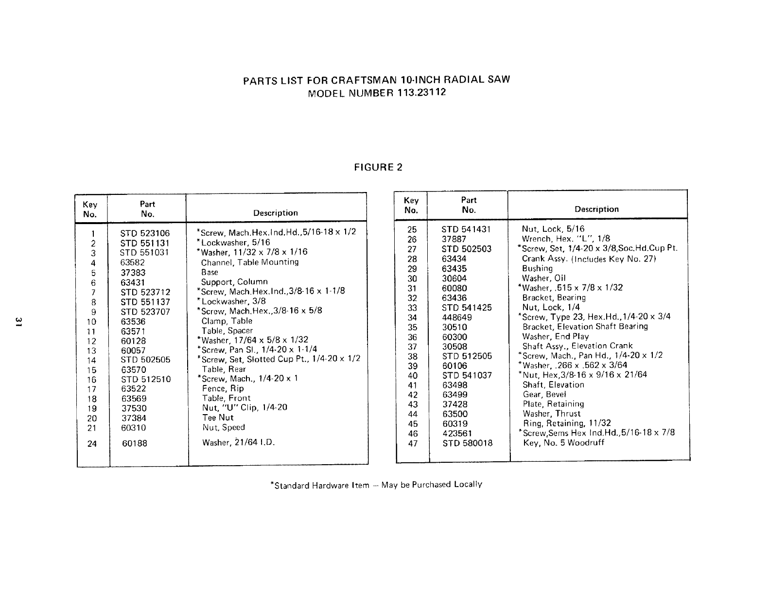
PARTS LIST FOR CRAFTSMAN 10-INCH RADIAL SAW
MODEL NUMBER 113.23112
FIGURE 2
Key Part
No. No. Description
1
2
3
4
5
6
7
8
9
10
11
12
13
14
15
16
17
18
19
20
21
24
STD 523106
STD 551131
STD 551O31
63582
37383
63431
STD 523712
_Screw, Mach.Hex.lnd.Hd.,5/16-18 x 1/2
* Lockwasher, 5/16
*Washer, 11/32 x 7/8 x 1/16
Channel, Table Mounting
Base
Support, Column
*Screw, Mach.Hex.lnd.,3i8-16 x 1-1/8
STD 551137
STD 523707
63536
63571
60128
60057
STD 502505
63570
STD 512510
63522
63569
37530
37384
60310
60188
* Lockwasher, 3/8
*Screw, Mach.Hex.,3/8-16 x 5/8
Clamp, Table
Table, Spacer
*Washer, 17/64 x 5/8 x 1/32
*Screw, Pan SI., 1/4-20 x 1-1/4
*Screw, Set, Slotted Cup Pt., 1/4-20 x 1/2
Table, Rear
*Screw, Mach., 1/4-20 x 1
Fence, Rip
Table, Front
Nut, "U" Clip, 1/4-20
Tee Nut
Nut, Speed
Washer, 51/64 I.D.
Key Part
No. No. Description
25
26
27
28
29
30
31
32
33
34
35
36
37
38
39
40
41
42
43
44
45
46
47
STD 541431
37887
STD 502503
63434
63435
30604
60080
63436
STD 541425
448649
30510
60300
30508
STD 512505
60106
STD 541037
63498
63499
37428
63500
60319
423561
STD 580018
Nut, Lock, 5/16
Wrench, Hex. "L", I/8
*Screw, Set, 1/4-20 x 3/8,Soc.Hd.Cup Pt.
Crank Assy. (Includes Key No. 27)
Bushing
Washer, Oil
*Washer, .515 x 7/8 x 1/32
Bracket, Bearing
Nut, Lock, 1/4
*Screw, Type 23, Hex.Hd.,1/4-20 x 3/4
Bracket, Elevation Shaft Bearing
Washer, End Play
Shaft Assy., Elevation Crank
*Screw, Mach., Pan Hd., 1/4-20 x 1/2
*Washer, .266 x .562 x 3/64
*Nut, Hex,3i8-16 x 9/16 x 21/64
Shaft, Elevation
Gear, Bevel
Plate, Retaining
Washer, Thrust
Ring, Retaining, 11/32
*Screw,Sems Hex Ind.Hd.,5/16-18 x 7/8
Key, No. 5 Woodruff
*Standard Hardware Item - May be Purchased Locally
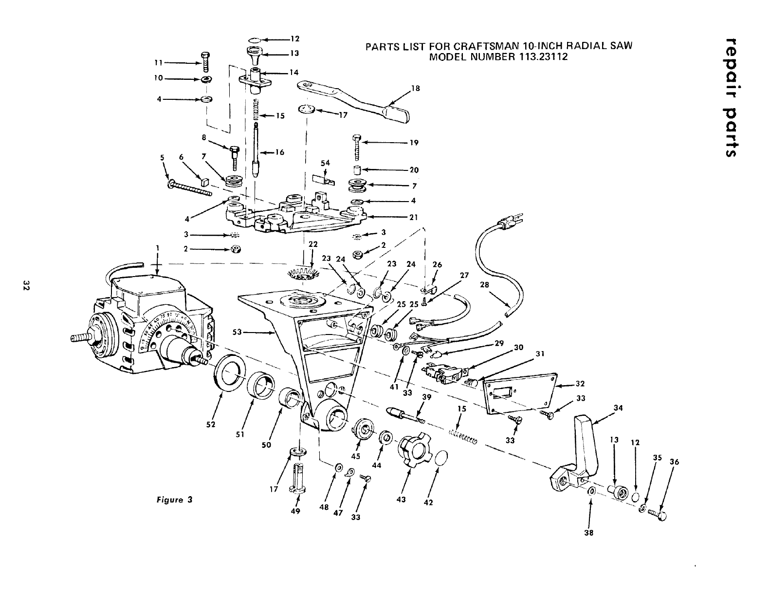
w
,,----__,._
I
C_-.-- 12 PARTS LIST FOR CRAFTSMAN 10-INCH RADIAL SAW
MODEL NUMBER 113.23112
22
23 24 J
23 24 26
27
m6
31
Figure 3
52
51
50
17 !
49 48
33 _
39
! !
43 42
33
33
38
34
J
|3 12
35 36
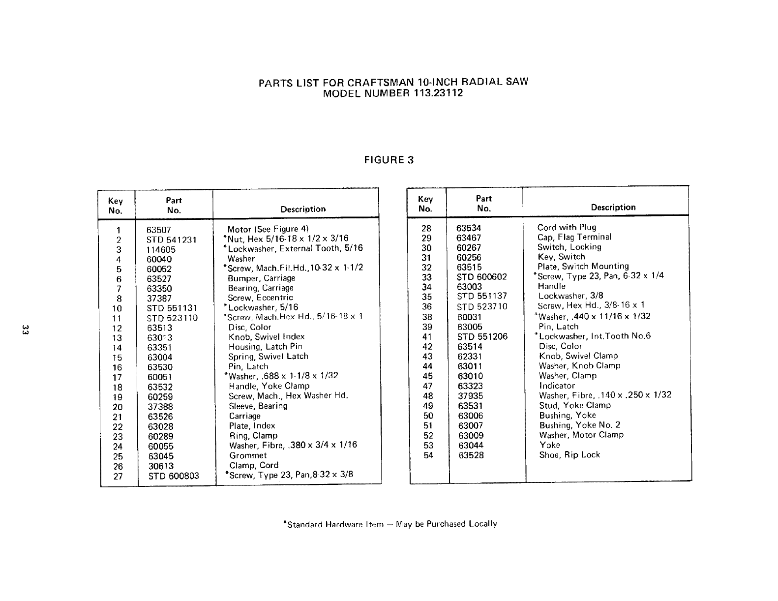
PARTS LIST FOR CRAFTSMAN 10-INCH RADIAL SAW
MODEL NUMBER 113.23112
FIGURE 3
Key Part
No. No. Description
1
2
3
4
5
6
7
8
10
11
!2
13
14
15
16
17
18
19
2O
21
22
23
24
25
26
27
63507
STD 541231
114605
60040
60052
63527
63350
37387
STD 551131
STD 52311O
Motor (See Figure 4)
*Nut, Hex 5/16-18 x 1/2x 3/16
*Lockwasher, External Tooth, 5/16
Washer
*Screw, Mach.FiI.Hd.,l(_32 x 1-1/2
Bumper, Carriage
Bearing, Carriage
Screw, Eccentric
* Lockwasher, 5/16
*Screw, Mach.Hex Hd., 5/16-18 x 1
63513
63013
63351
63004
63530
60051
63532
60259
37388
63526
63028
60289
60055
63045
30613
STD 600803
Disc, Color
Knob, Swivel Index
Housing, Latch Pin
Spring, Swivel Latch
Pin, Latch
*Washer, .688 x 1-1/8 x 1/32
Handle, Yoke Clamp
Screw, Mach., Hex Washer Hd.
Sleeve, Bearing
Carriage
Plate, Index
Ring, Clamp
Washer, Fibre, .380 x 3/4 x 1/16
Grommet
Clamp, Cord
*Screw, Type 23, Pan,832 x 3/8
Key Pa_
No. No. Description
28
29
30
31
32
33
34
35
36
38
39
41
42
43
44
45
47
48
49
5O
51
52
53
54
63534
63467
60267
60256
63515
STD 600602
63003
STD 551137
STD 523710
60031
63005
STD 551206
63514
62331
63011
63010
63323
37935
63531
63006
63007
63009
63044
63528
Cord with Plug
Cap, Flag Terminal
Switch, Locking
Key, Switch
Plate, Switch Mounting
*Screw, Type 23, Pan, 6-32 x 1/4
Handle
Lockwasher, 3/8
Screw, Hex Hd., 3/8-16 x 1
*Washer, .440 x 11/16 x 1/32
Pin, Latch
*Lockwasher, Int.Tooth No.6
Disc, Color
Knob, Swivel Clamp
Washer, Knob Clamp
Washer, Clamp
Indicator
Washer, Fibre, .140 x .250 x 1/32
Stud, Yoke Clamp
Bushing, Yoke
Bushing, Yoke No. 2
Washer, Motor Clamp
Yoke
Shoe, Rip Lock
*Standard Hardware Item - May be Purchased Locally
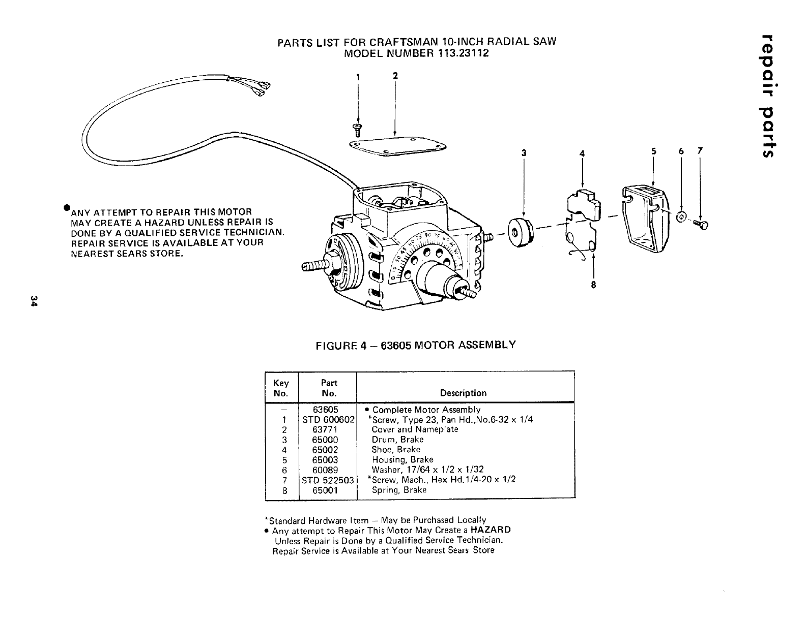
OANY ATTEMPT TO REPAIR THIS MOTOR
MAY CREATE A HAZARD UNLESS REPAIR IS
DONE BY AQUALIFIED SERVICE TECHNICIAN.
REPAIR SERVICE IS AVAILABLE AT YOUR
NEAREST SEARS STORE.
PARTS LIST FOR CRAFTSMAN 10-INCH RADIAL SAW
MODEL NUMBER 113.23112
1
I
3 4 5 6 7
'13
Q
DO
!3
Q
,,,-IP
t_
FIGURE 4 - 63605 MOTOR ASSEMBLY
Key Part
No. No. Description
- 63605
1 STD 600602
2 63771
3 65O00
4 65002
5 65OO3
6 6O089
7 STD 522503
8 65001
• Complete Motor Assembly
*Screw, Type 23, Pan Hd,No.6-32 x 1/4
Cover and Nameplate
Drum, Brake
Shoe, Brake
Housing, Brake
Washer, 17/64 x 1/2 x 1/32
*Screw, Mach., Hex Hd.1/4-20 x 1/2
Spring, Brake
*Standard Hardware Item - May be Purchased Locally
• Any attempt to Repair This Motor May Create a HAZARD
Unless Repair is Done by a Qualified Service Technician.
Repair Service is Available at Your Nearest Sears Store
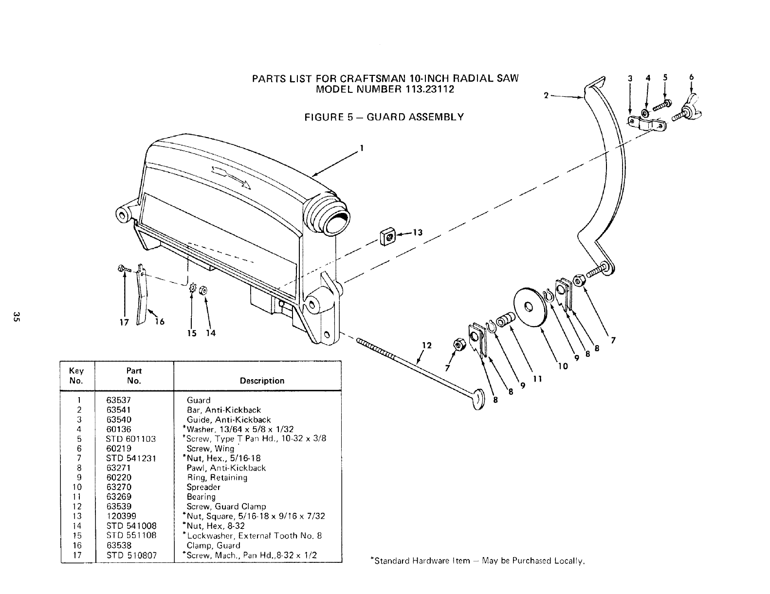
PARTS LIST FOR CRAFTSMAN 10-INCH RADIAL SAW
MODEL NUMBER 113.23112
FIGURE 5- GUARD ASSEMBLY
345 6
17 J16
15 14
Key Part
No. No. Description
1 63537
2 63541
3 63540
4 60136
5 STD 601103
6 60219
7 STD 541231
8 63271
9 60220
10 63270
11 63269
12 63539
13 120399
14 STD 541008
15 STD 551108
16 63538
17 STD 510807
Guard
Bar, Anti-Kickback
Guide, Anti-Kickback
*Washer. 13/64 x 5/8 x 1/32
*Screw, Type T Pan Hd., 10-32 x 3/8
Screw, Wing
*Nut, Hex., 5/16-18
Pawl, Anti-Kickback
Ring, Retaining
Spreader
Bearing
Screw, Guard Clamp
*Nut, Square, 5/16-18 x 9/16 x 7/32
*Nut, Hex, 8-32
*Lockwasher, External Tooth No. 8
Clamp, Guard
*Screw, Mach., Pan Hd.,8 32 x 1/2
j
J
J
J
12
10
11
*Standard Hardware Item - May be Purchased Locally.
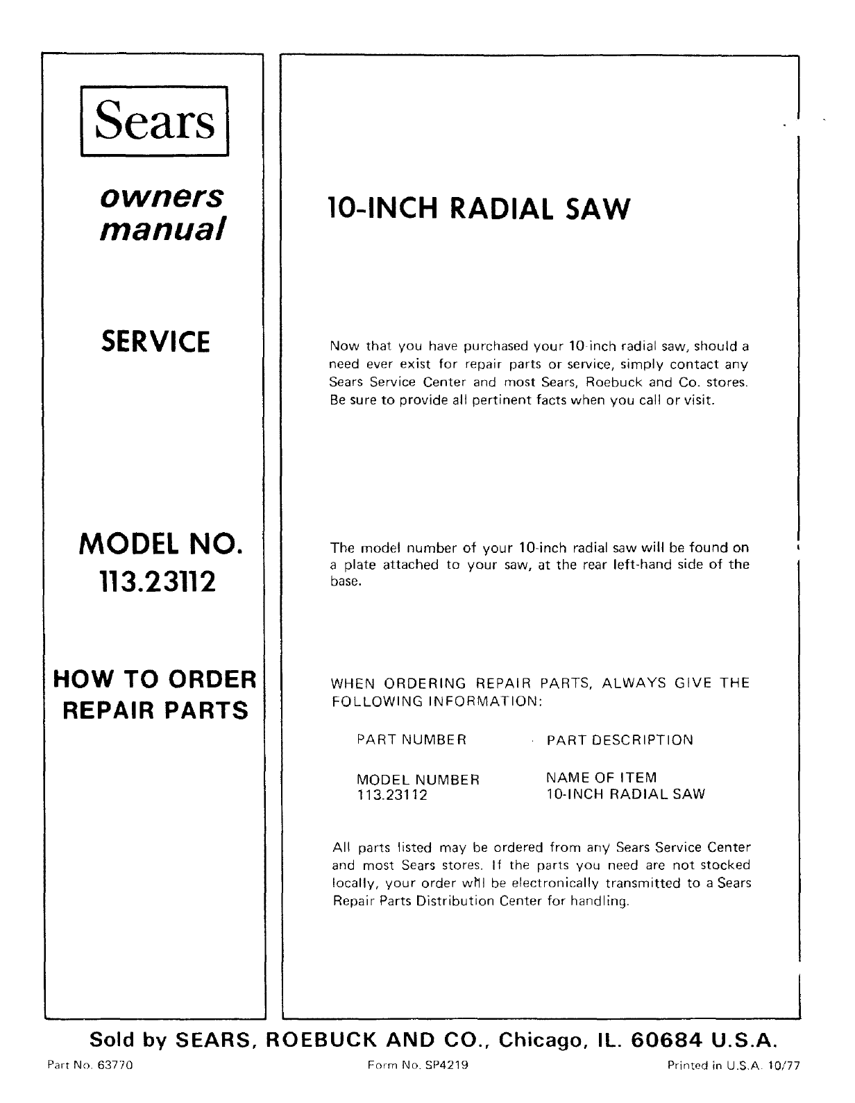
ISearsi
owners
manual
SERVICE
MODEL NO.
113.23112
HOW TO ORDER
REPAIR PARTS
IO-INCH RADIAL SAW
Now that you have purchased your 10 inch radial saw, should a
need ever exist for repair parts or service, simply contact any
Sears Service Center and most Sears, Roebuck and Co. stores.
Be sure to provide all pertinent facts when you call or visit.
The model number of your 104nch radial saw will be found on
a plate attached to your saw, at the rear left-hand side of the
base.
WHEN ORDERING REPAIR PARTS, ALWAYS GIVE THE
FOLLOWING INFORMATION:
PART NUMBER
MODEL NUMBER
113.231t2
PART DESCRIPTION
NAME OF ITEM
10-INCH RADIAL SAW
All parts listed may be ordered from any Sears Service Center
and most Sears stores. If the parts you need are not stocked
locally, your order wPll be electronically transmitted to a Sears
Repair Parts Distribution Center for handling.
I
Sold by SEARS, ROEBUCK AND CO., Chicago, IL. 60684 U.S.A.
Part No. 6377Q Form No. SP4219 Printed in U.S.A. 10/77
