Craftsman 11323161 User Manual 10 INCH RADIAL SAW Manuals And Guides 1104617L
User Manual: Craftsman 11323161 11323161 CRAFTSMAN CRAFTSMAN 10-INCH RADIAL SAW - Manuals and Guides View the owners manual for your CRAFTSMAN CRAFTSMAN 10-INCH RADIAL SAW #11323161. Home:Tool Parts:Craftsman Parts:Craftsman CRAFTSMAN 10-INCH RADIAL SAW Manual
Open the PDF directly: View PDF ![]() .
.
Page Count: 36
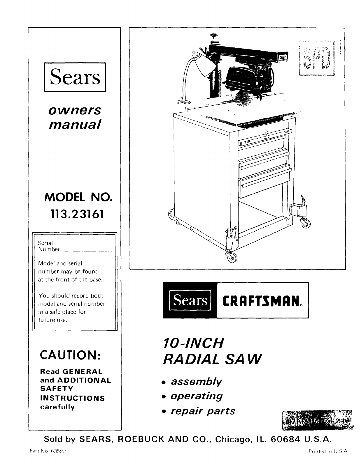
Sears
owners
manual
MODEL NO.
113.23161
Serial
Number
Model and serial
number may be found
at the front of the base.
You should record both
model and serial number
in a safe place for
future use.
CAUTION:
I
t
Read GENERAL
and ADDITIONAL
SAFETY
INSTRUCTIONS
carefully
Sold by SEARS,
Par1 No 63592
"4-- .........
:,---, f_t-_
+
CRRFTSMRN_
IO-INCH
RADIAL SAW
•assembly
•operating
•repair parts
ROEBUCK AND CO., Chicago, IL. 60684 U.S.A.
Prlrll*'<l in LJ S _
FULL ONE YEAR WARRANTY ON CRAFTSMAN RADIAL SAWS
If within one year from the date of purchase, this Craftsman Radtal Saw fails due to a defect in material or
workmanship, Sears wtll repair it, free of charge.
Warranty service is available by simply contacting the nearest Sears store or Servtce Center throughout the
United States.
Th=s warranty gives you specific legal rights, and you may also have other rights which vary from state to
state. SEARS, ROEBUCK AND CO.
BSC 41-3
SEARS TOWER
CHICAGO, IL 60684
general safety instructions for power tools
1. KNOW YOUR POWER TOOL
Rt._(J the owner's manual carefully Learn tts
alxrlmat_or_ and I_m_tat=ons as well as the spec=f=c
pot.;nt_al hazards pecul_a_ to th_s tool
2. GROUND ALL TOOLS
Th,s tool _s equipped with an approved 3-conducto_
cord and a 3-prong g_oundmg type plug to fit the
prt,per grounding type receptacle The green conductor 15.
m the cord _s the grounding w_re Never connect the
gr,en wJre to a I.v__ terminal
3. KEEP GUARDS IN PLACE
_n working order, and m proper adlustment and
al_qnment.
4. REMOVE ADJUSTING KEYS
AND WRENCHES
FC,l m habit of (:heckubg to se,: that keys and adlustmg
wr..nche.s are r,moved from tt)ol b+_for(' tell]inS it on
5. KEEP WORK AREA CLEAN
Oh,ft_rprl areas and bench-_s mwte acodents Floor
mL t not b__slippery due to wax or sawdust
6. AVOID DANGEROUS ENVIRONMENT
Don't use power- tools _n damp or wet Iocat+ons or
ex_)ose them to rain. Keep work area well Irghted.
Provide adequate surrounding work space. 19.
7. KEEP CHILDREN AWAY
All ,_,s,tors should be kept a gale distance from work
dre ;
8. MAKE WORKSHOP KID-PROOF
-,_th padlock,, master sw_tches, or by remowng
sta, Ter key's 20.
9. DON'T FORCE TOOL
It ._!1 do the job better and safe= at the rate fo_ whmh
,t ',,Js cte_gned
10. USE RIGHT TOOL
Do _'t force tool or attachment to do a lOb _t was not
de-_gr,ed for
11. WEAR PROPER APPAREL
Do f_ot wear loose clothing, gloves, neckbes or lewelrv
(r,_ qs, ',,,.r_st watches} to get caught in mowng parts
Noasl_p footwear is _ecommended. Wear protecbv_ 21.
ha_ co,,.murg to contain long hair Rol! long sleeves
alr, ,_. th- ,:lbow
12. USE SAFETY GOGGLES (Head Protection)
'd,,'t ,r Saf-tv gogqh_s (mLmt Cf)ITI['IJ'y ,.%'lth ANS Z87 1 ) .Jr 22.
rill tlr_les Also, LlSf • facP ot (lust nlask If t.Llttlrlq
O H, Idt_Orq t'_ dLJ_,ty, and L_r protf'ctors (pILros OI C_rLIffs)
dlH _lg e'xt,::ld_d l]ellOdS of operat=on
13. SECURE WORK
Use clamps or a wse to hold work when practical It's
safer than usmgyour hand, frees both hands to operate
tool.
14. DON'T OVERREACH
Keep proper footing and balance at all umes.
MAINTAIN TOOLS WITH CARE
Keep tools sharp and clean for best and safest
performance Follow mstrucbons for lubricating and
changing accessories
16. DISCONNECT TOOLS
before serwcmg, when changing accessor=es such as
blades, b_ts, cutters, etc.
17. AVOID ACCIDENTAL STARTING
Make sure switch _s In "OFF" posluon before plugging
H]
18. USE RECOMMENDED ACCESSORIES
Consult the owner's manual for recommended
accessories Follow tire instructions that accompany
the accessories The use of _mproper accessories may
cause hazards
NEVER STAND ON TOOL
Serious mlu_y could occur _f the tool _st_pped or _f the
cutting tool _saccidentally contacted
Do not store rnater_als above or near the tool such that
rt _snecessary to stand on the tool to reach them
CHECK DAMAGED PARTS
Before further use of the tool, a guard o_ other [)art that
_<damaged should be carefully checked to ensure that _t
,v_ll operate propelly drld p_rform _ts _ntended furlCt_Orq
Check for alignment of mowng parts, binding of mo_'_ng
parts, breakag_ of parts, mounting, and any other
concht_orls that may affect _ts operation A guard or
ogler part tlhat _s damaged should be properly repaired
or replaced
DIRECTION OF FEED
Feed ,azr)rk into a hlad_ or cutter aqau_st the d_re('t_on
ot rotation of the blade or cutter only
NEVER LEAVE TOOL RUNNING
UNATTENDED
TL. trl pOV_,_I utt Don't leaw' tool ur_t_l tl cOr_ltrs to J
COil]pit] [e stop
additional safety instructions for radial saws
WARNING: DO NOT CONNECT POWER CORD UNTIL
THE FOLLOWING STEPS HAVE BEEN
SATISFACTORI LY COMPLETED:
A. Assembly and installation.
B. Examination and operating famdiarity with ON-OFF
switch, elevation control, bevel index and lock, carriage
lock, guard clamp screw, spreader and anti-kickback
device, and miter index and lock.
C. Review and understanding of the Safety Instructions
and Operating Procedures which follow.
CAUTION: Always disconnect the power cord before
removing the guard, changing the cutting tool, changing
the set-up or making adjustments. Shut off motor
before performing layout work on the saw table.
ALWAYS RETURN THE CARRIAGE TO THE FULL
REAR POSITION AFTER EACH CROSSCUT TYPE
OPERATION.
STABILITY
1. The saw should be bolted down if there is any tendency
to tip, walk, or slide during normal operation. The saw
table should be approximately 39" above the floor.
WORK AREA AND MACHINE POSITION
1. Position your entire saw (or saw and bench) to slope
slightly rearward, so the carriage will not roll forward
due to gravity or vibration.
2. The saw should be positioned when ripping so neither
the operator nor a casual observer is forced to stand in
line with the saw blade.
3. The saw work area should have adequate overhead,
non-glare light and adequate surrounding work space.
4. Set carriage lock before moving machine.
KICKBACKS-COMMON WAYS THEY CAN HAPPEN
Kickbacks can cause serious injury: A kickback occurs
when a part of the workpiece binds between the saw blade
and the rip fence or other fixed object, rises from the table,
and is thrown toward the operator. Kickbacks are usually
caused by one or more of the following conditions
1. Failure to determine that the saw blade is parallel to the
rip fence.
2. Confining the cut-off piece when ripping.
3. Failure to use the spreader when ripping, or failure to
maintain the spreader in alignment with the saw blade.
4. Ripping wood that has a twisted grain, does not have a
straight edge to guide along the fence, or wood that is
twisted or not flat (which may rock on the table and
pinch the blade).
5. Improperly conditioned (dull) saw that permits the
material to pinch on the out-feed edge of the saw and
rise from the table.
6. R_pping by applying the feed force to the section of the
workpiece that will become the cut-off (free) piece
(feed force when ripping should always be applied
between the saw blade and the fence . . use a push
st_ck for narrow or short work).
7. Releasing workpiece before operation is complete ...
not pushing the workpiece all the way past the saw
blade.
8. Failure to adjust the nose of the guard to just clear the
workpiece.
KICKBACKS -- COMMON WAYS THEY CAN BE
AVOIDED OR INJURY FROM THEM PREVENTED OR
MINIMIZED
1. Avoiding any of the causes noted above.
2. Keeping your face and body - and observers - always
out of line of possible kickbacks.
3. Always wear safety goggles.
4. Making sure (by trial) before starting the cut that the
anti-kickback pawls will stop kickback once it has
started.
5. Whenever possible, perform rip, bevel rip, and plough
cuts with the saw in the in-rip position. Refer to "6"
under "Kickbacks - ... Happen" and "6" under
"Operational Instructions."
6. Keeping points of anti-kickback pawls SHARP!
7. Positioning nose of guard to .just clear work and
positioning anti-kickback pawls properly.
8. Plastic and composition (like hardboard) materials may
be cut on your saw. However, since these are usually
quite hard and slippery, the anti-kickback pawls may
not stop a kickback.
Therefore, be especially attentive to following proper
set-up and cutting procedures for ripping these
materials. Do not stand, or permit anyone else to stand,
in line with a potential kickback.
PERSONAL CLOTHING AND EQUIPMENT
1. Do not wear gloves while operating the saw. Loose
flowing garments, jewehv (rings, wrist watches, etc.)
and neckties must never be worn. Long sleeves must be
rolled to above the elbows.
2. Always wear safety goggles, (complying with ANS
Z87.1-1968) to protect the eyes. In addition, wear a
face shield if the operation is dusty, and ear protectors
(plugs or muffs) dunng extended periods of operation.
OPERATIONAL INSTRUCTIONS
1. Before starting work, verify that no play exists in the
carriage, and that arm, yoke, and bevel locks/clamps are
tight.
2. Never place your fingers or hands in the path of the saw
blade.
3. Use only accessories that are designed for this machine.
4, A large proportion of saw accidents is caused by dull,
badly set, improperly filed cutting tools, by gum or
resin adhering to cutting tools, and by saw blade
misahgnment (out-of-parallel) with the fence. Such
conditions cause the material to st_ck, jam, stall the
saw, or kickback at the operator. NEVER ATTEMPT
TO FREE A STALLED SAW BLADE WITHOUT
FIRST TURNING THE SAW "OFF". Avoid potential
injury by proper cutting tool and machine maintenance.
3
CAUTION: DO NOT cycle the motor switch ON and
OFF rapidly, as this might cause the saw blade to
loosen. In the event this should ever occur, allow the
saw blade to come to a complete stop and re-tighten the
arbor nut normally, not excessively.
additional safety instructions for radial saws
6. Prowde proper support for the workptece, based on its
slzf and the type of operation to be performed. Hold
the work brmly against tile fence. When ripping short
wo_kpieces (under 12-_nches long) or narrow pieces
(under 64nches wide}, use a push stick applied to the
section of the workp_ece between the blade and the
fence.
7. Never use a length stop on the free end or edge of the
workpiece whether crosscutting or ripping. Never hang
onto or touch the free end of workpiece, or a free piece
that is cut off, while power _s "'ON'" and/or the saw
blade is rotating. In short, to guard against kickbacks or
other potential accidents, the cut-off piece in any
thru-sawmg operation must never be confined - It must
be allowed to move laterally.
8. Do not leave a long board unsupported so the spring of
tht. board causes it to shift on the table. A support
sh(luld be used to catch the end of the board you are
cutting.
9. Whenever you have a choice, use the "IN-RIP" (instead
of "OUT-RIP") setup. This provides more space on the
fence side of the blade in which to use a push stick.
10. Make sure your fingers do not contact the terminals of
power or motor plugs when installing or removing the
plug to or from a live power source.
11. Never climb on or- near the saw when power is on
Never leave the saw with power on, or before the
cutting tool has come to a complete stop. Lock the
motor switch and put away the key when leaving the
saw.
12. Avoid awkward hand positions, where a sudden shp
could cause a hand to move into a sawblade or other
cutting tool. Never reach in back of or around the
cutting tool with either hand to hold down the
w_)rk piece.
CAUTION: Never reposition the Guard or
anti-kickback/spreader with power ON.
13. Always posihon the GUARD and the anti-Mckhack and
spreader assembly for rtp type operations. Also make
sure the cutting tool, arbor collars and arbor nuts are
installed properly. Keep guard in place.
14. When performing crosscut type operations, be sure the
Guard is clamped solidly in the horizontal position, and
tt'_ anti-kickback assembly is adjusted so the pawls just
cl,ar the workpiece. Tighten securely. ThDs provides
additional guarding.
15. Never operate this saw when equipped with a molding
h,-ad unless the proper molding head guard _s tnstalled
- see listing of recommended accessories. The only
excephon _s when "'top-s_de'" molding when the
sawblade guard must be used. See detailed instructions
that accompany the molding head and molding head
guard.
16. Dr) not use any blade or other cutting tool marked for
arl operating speed lower than 3450 RPM. Never use a
cutting tool larger _n d_ameter than the diameter for
which the saw was designed For greatest safety and
efftc]ency when ripping, use the maximum d_ameter
blade for which the saw _s designed, since under these
c,Jnd_t_ons the spreader is nearest the blade.
17. ]he use of abraswe or cut-off wheels, or w_re wheels
can be dangerous and _s not recommended. (Abraswe or
cJt-off wheels are used to saw marly different materials
m.;lud_ng metals, stone, and glass.)
18 [_., not postt{on the arm so the operation you are
performing permits the cutting tool to extend beyond
the edges of the table.
19. Never- turn your radial arm saw "ON" before clearing
the table or work surface of all objects (tools, scraps of
wood, etc.) except the workplece and related feed or
support devices for the operation planned.
20
21.
22.
23.
24.
25.
Objects can be thrown upward toward the operator by
the back of the blade if proper operating procedures are
not followed during cross-cut type operations. Th_s
usually occurs when a small loose piece of wood or
other objects contacts the rear of the revolwng blade
and ricochets off the fence or the wall behind the saw
toward the operator. It can be avoided by removing all
loose pieces from the table immeidately after they are
made, using a long st_ck, and keeping the guard _n place
at all times.
DO NOT perform layout, assembly, or setup work on
the table while the cutting tool ir rotating.
Never perform any operahon "free hand". Th_s term
means feeding the carriage into the workpiece or
feeding the workpiece into the saw blade or other
cutting tool without using the fence or some other
device which prevents rotation or twisting of the
workpiece during the operation. Never "'rip" (cut with
the grain) narrow or long workpieces m the crosscut
pos_t_on. Never make a miter cut with the arm in the
90 ° crosscut position.
"ALWAYS return the carriage to the full rearward
posit_on at conclusion of each crosscut type cut. Never
remove your hand from the bevel index handle unless
the carriage is m this positron. Otherwise the cutting
tool may climb up on the workpiece and be propelled
toward you."
"Never lower a revolving cutting tool into the table or a
workplece without first locking the Carriage Lock
Knob. Release the knob only after grasping the Bevel
Index Handle. Otherwise the cutting tool may grab the
workplece and be propelled toward you."
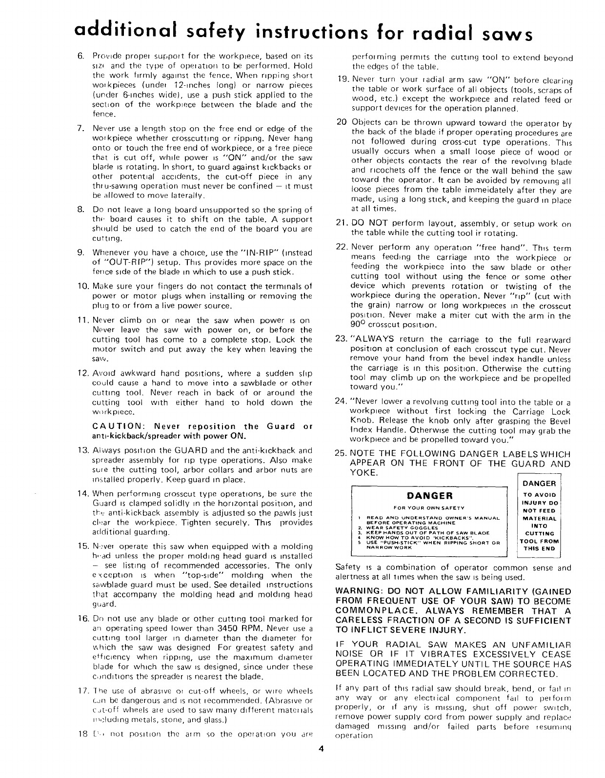
NOTE THE FOLLOWING DANGER LABELSWHICH
APPEAR ON THE FRONT OF THE GUARD AND
YOKE.
DANGER
FOR YOUR OWN SAFETY
IREAD AND UNDERSTAND OWNER'S MANUAL
BEFORE OPERATING MACHINE
2. WEAR SAFETY GOGGLES
3. KEEP I_ANDS OUT OF PATH OF SAW BLADE
4 KNOW HOW TO AVOID "KICKBACKS".
SUSE "PUSH-STICK" WHEN RIPPING SHORT OR
NARROW WORK
DANGER
TO AVOID
INJURY DO
NOT FEED
MATERIAL
INTO
CUTTING
TOOL FROM
THIS END I
Safety _s a combination of operator common sense and
alertness at all t_mes when the saw ts being used.
WARNING: DO NOT ALLOW FAMILIARITY (GAINED
FROM FREQUENT USE OF YOUR SAW) TO BECOME
COMMONPLACE. ALWAYS REMEMBER THAT A
CARELESS FRACTION OF A SECOND IS SUFFICIENT
TO INFLICT SEVERE INJURY.
IF YOUR RADIAL SAW MAKES AN UNFAMILIAR
NOISE OR IF IT VIBRATES EXCESSIVELY CEASE
OPERATING IMMEDIATELY UNTILTHE SOURCE HAS
BEEN LOCATED AND THE PROBLEM CORRECTED.
If any part of this radial saw should break, bend, or fa_! m
any way or any electrical component fa_l to perform
properly, or ff any is m_ssmg, shut off power sw_tch,
remove power supply cord from power supply and replace
damaged m_sslng and!or failed parts before _esummq
operation
unpacking and pre-assembly
CONTENTS
Page
Safety Instructions ....................... 2,3,4 & 5
Unpacking and Pre-Assembly ..................... 5
Assembly and Adjustments ...................... 6
Operating Controls ........................... 13
Basic Saw Operations .......................... 15
'age
Electrical Connections ......................... 18
Trouble Shooting ............................. 20
Recommended Accessories ..................... 25
Motor Trouble-Shooting Chart ................... 26
Repair Parts ................................. 27
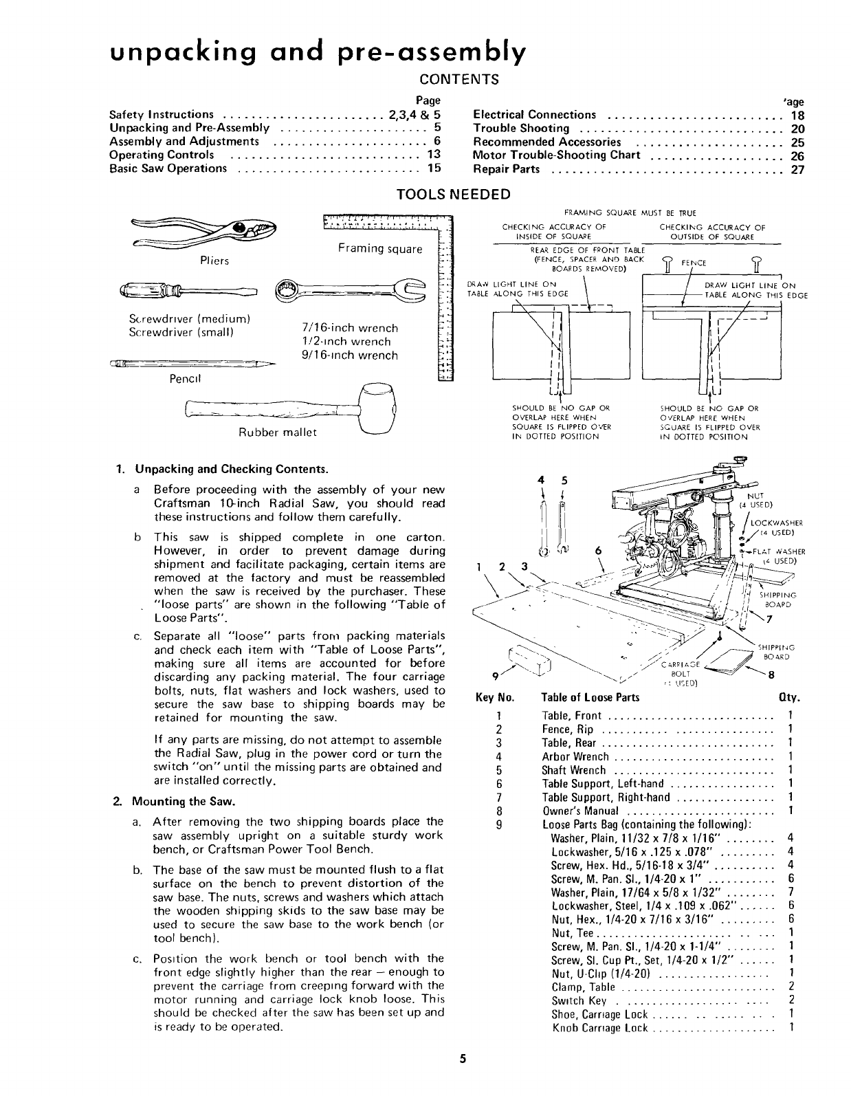
TOOLS
Pliers
_..,...,L_,.,, r.,., ,.: ,r,.
', ,_ '&, ............. t I,,.j,',,_L
Framing square
Screwdrwer (medium)
Screwdriver (small) 7/16-inch wrench
1!2-inch wrench
9/16-inch wrench
Pencil
NEEDED
FRAMING SQUARE MUST BE TRUE
CHECKING ACCURACY OF CHECKING ACCURACY OF
INSIDE OF SQUARE OUTSIDE OF SQUARE
REAR EDGE OF FRONT TABLE
(FENCE, SPACER AND BACK FEINCE ?
BOARDS REMOVED) <_ /
DRA,_LIGHTLINEON \ |/DRAW UO.TUNE'ON
TABLE ALONG THIS EDGE _ I_/L_ fABLE ALONG THIS EDGE
SHOULD BE NO GAP OR SHOULD BE NO GAP OR
OVERLAP HERE WHEN O'VERLAP HERE WHEN
SQUARE IS FLIPPED O%{R SCLJARE IS FLIPPED OVER
11",4 DOTTED POSITION IN DOTTED POSITION
1. Unpacking and Checking Contents.
aBefore proceeding with the assembly of your new
Craftsman 10-inch Radial Saw, you should read
these instructions and follow them carefully.
b This saw is shipped complete in one carton.
However, in order to prevent damage during
shipment and facilitate packaging, certain items are
removed at the factory and must be reassembled
when the saw is received by the purchaser. These
"loose parts" are shown in the following "Table of
Loose Parts".
c. Separate all "loose" parts from packing materials
and check each item with "Table of Loose Parts",
making sure all items are accounted for before
discarding any packing material. The four carriage
bolts, nuts, flat washers and lock washers, used to
secure the saw base to shipping boards may be
retained for mounting the saw.
2.
If any parts are missing, do not attempt to assemble
the Radial Saw, plug in the power cord or turn the
switch "on" until the missing parts are obtained and
are installed correctly.
Mounting the Saw.
a. After removing the two shipping boards place the
saw assembly upright on a suitable sturdy work
bench, or Craftsman Power Tool Bench.
b. The base of the saw must be mounted flush to a flat
surface on the bench to prevent distortion of the
saw base. The nuts, screws and washers which attach
the wooden shipping skids to the saw base may be
used to secure the saw base to the work bench (or
tool bench).
C. Posttion the work bench or tool bench with the
front edge slightly higher than the rear - enough to
prevent the carriage from creeping forward with the
motor running and carriage lock knob loose. This
should be checked after the saw has been set up and
is ready to be operated.
I I/I _LL_---_,;'_L,_L_ till _'/_,_ useea
• " -- ---_ _-____'.,', _- _.I
_'_'/ ,'- EISED)
Key No. Table of Loose Parts Qty.
1Table, Front ........................... 1
2 Fence, Rip ........................... 1
3Table, Rear ............................ 1
4Arbor Wrench .......................... 1
5Shaft Wrench .......................... 1
6Table Support, Left-hand ................. 1
7 Table Support, Right-hand ................ 1
8 Owner's Manual ........................ 1
9 Loose Parts Bag (containing the following):
Washer, Plain, 11/32 x 7/8 x 1/16" . ....... 4
Lockwasher, 5/16 x .125 x .078" . ........ 4
Screw, Hex. Hd., 5/16-18 x 3/4" . ......... 4
Screw, M. Pan. SI., 1/4-20 x 1" . .......... 6
Washer, Plain, 17/64 x 5/8 x 1/32" . ....... 7
Lockwasher, Steel, 1/4 x .109 x .062". ..... 6
Nut, Hex., 1/4-20 x 7/16 x 3/16" . ........ 6
Nut, Tee ........................... 1
Screw, M. Pan. SI., 1/4-20 x 1-1/4'" ........ 1
Screw, SI. Cup Pt., Set, 1/4-20 x 1/2" . ..... 1
Nut, U-Chp (1/4-20) .................. 1
Clamp, Table ......................... 2
Sw_tch Key ....................... 2
Shoe, Carnage Lock ................ 1
Knob Carnage Lock .................... 1
assembly and adjustments
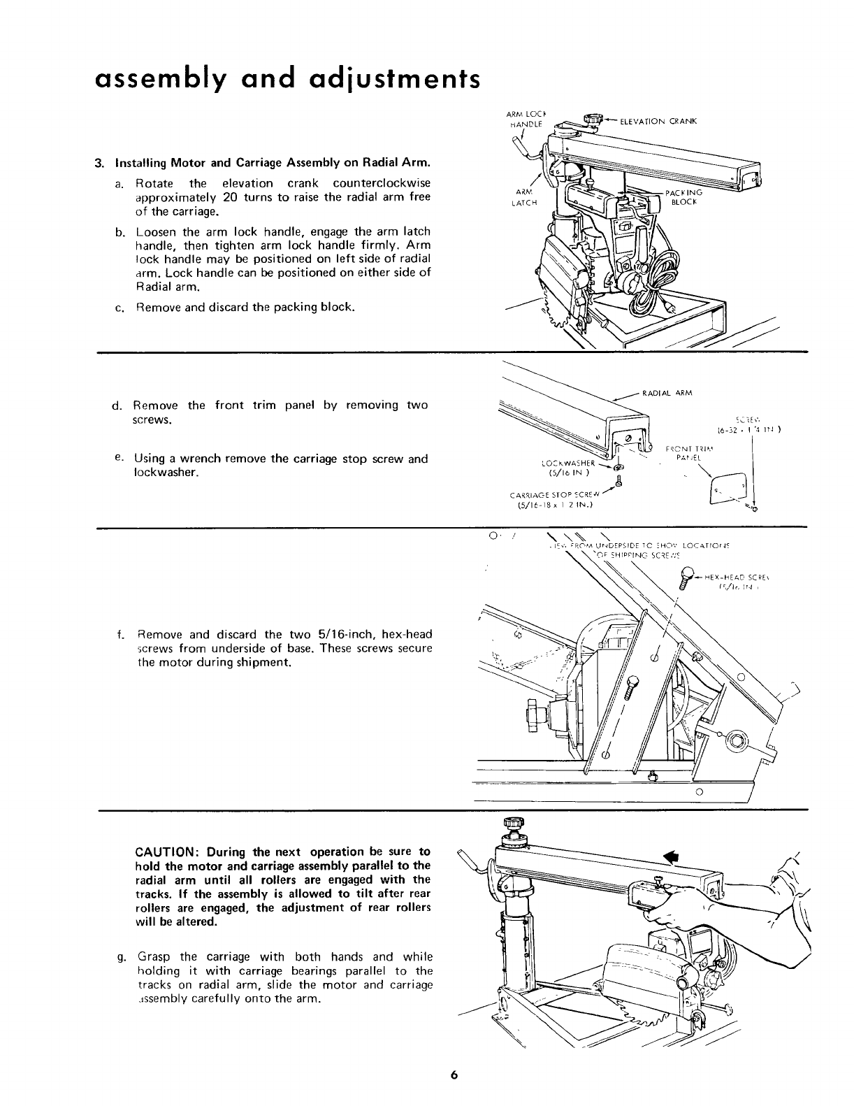
3. Installing Motor and Carriage Assembly on Radial Arm.
a.
b.
ARM LOCI'
Rotate the elevation crank counterclockwise
approximately 20 turns to raise the radial arm free
of the carriage.
Loosen the arm lock handle, engage the arm latch
handle, then tighten arm lock handle firmly. Arm
lock handle may be positioned on left side of radial
arm. Lock handle can be positioned on either side of
Radial arm.
c. Remove and discard the packing block.
d. Remove
screws.
e.
the front trim panel by removing two
Using a wrench remove the carriage stop screw and
Iockwasher.
PAC KING
BLOCI¢
f. Remove and discard the two 5/16-inch, hex-head
screws from underside of base, These screws secure
the motor during shipment.
o, ..' \ \% \
• IE_', CRC',M U_4DEPSIDE TC ZHO',' LOCATIOt4_
_X'_._H rPP I NIG SC _E ,',Lc
" __ _-- HEX-HEAD SCRE,
,,_t (fi,/Ir, fr4 ,
}% X
i, ,,ot
g.
CAUTION: During the next operation be sure to
hold the motor and carriage assembly parallel to the
radial arm until all rollers are engaged with the
tracks. If the assembly is allowed to tilt after rear
rollers are engaged, the adjustment of rear rollers
will be altered.
Grasp the carriage with both hands and while
holding it with carriage bearings parallel to the
tracks on radial arm, slide the motor and carriage
._ssembly carefully onto the arm. \
6
C._,RR[&OE CO..'ER _k H )CARRIAGE
LOCK SHOE
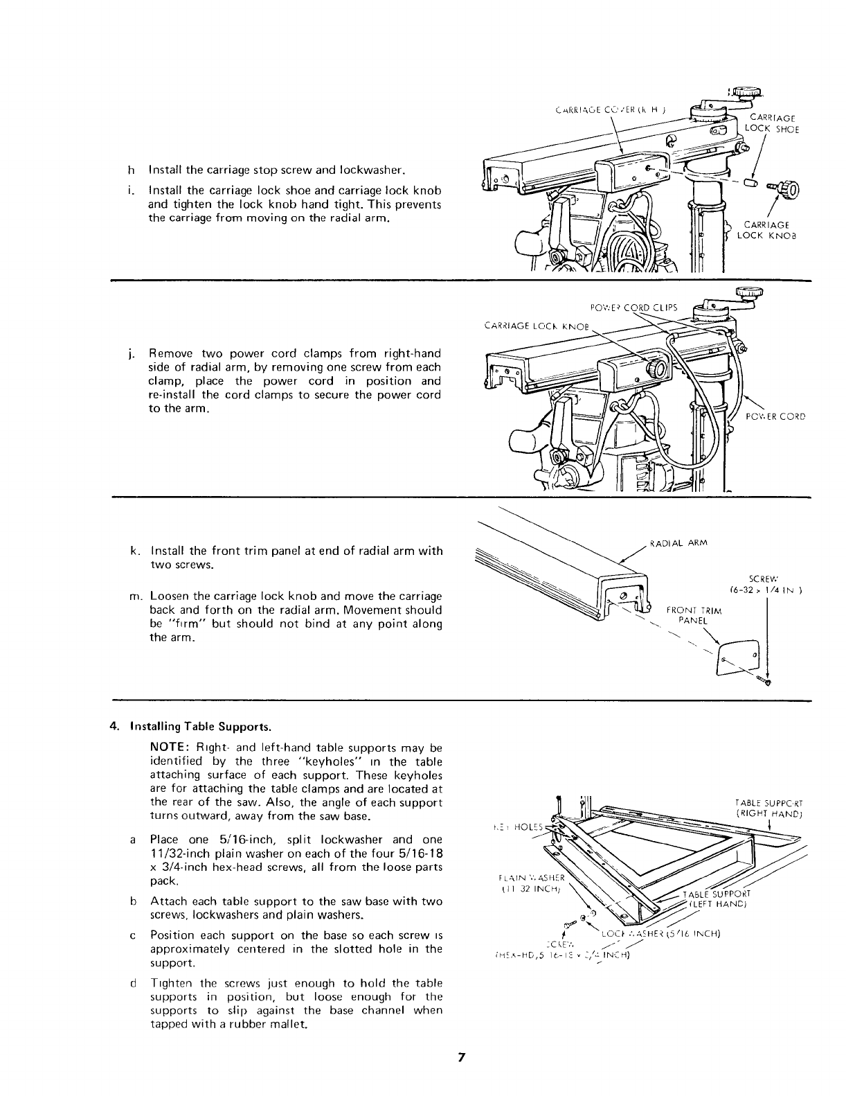
h
i.
Install the carriage stop screw and Iockwasher.
Install the carriage lock shoe and carriage lock knob
and tighten the lock knob hand tight. This prevents
the carriage from moving on the radial arm. CARRIAGE
LOCK KNOB
Remove two power cord clamps from right-hand
side of radial arm, by removing one screw from each
clamp, place the power cord in position and
re-install the cord clamps to secure the power cord
to the arm.
PO'¢.'E _ CORD CLIPS .__
I__
k. Install the front trim panel at end of radial arm with
two screws.
m. Loosen the carriage lock knob and move the carriage
back and forth on the radial arm. Movement should
be "firm" but should not bind at any point along
the arm.
__ RADIAL ARM
___ SCREW
4. Installing Table Supports.
NOTE: R_ght- and left-hand table supports may be
identified by the three "keyholes" in the table
attaching surface of each support. These keyholes
are for attaching the table clamps and are located at
the rear of the saw. Also, the angle of each support
turns outward, away from the saw base.
a Place one 5/16-inch, split Iockwasher and one
11/32-inch plain washer on each of the four 5/16-18
x 3/4-inch hex-head screws, all from the loose parts
pack.
b Attach each table support to the saw base with two
screws, Iockwashers and plain washers.
c Position each support on the base so each screw _s
approximately centered in the slotted hole in the
support.
d Tighten the screws just enough to hold the table
supports in position, but loose enough for the
supports to slip against the base channel when
tapped with a rubber mallet.
t,-_ HOLrS,_r_
[L,_IN ',', z,,SH_.R "_
t I I 32 lINCH) \
f
_C LE',',
_lJ _ TABLE SUPPC, RT
LC, C_" ,',A_HE< K,5 16 INCH)
it" J
;HE,_-HD,5 16-12 _ _z/_' INCH}
/
assembly and adjustments
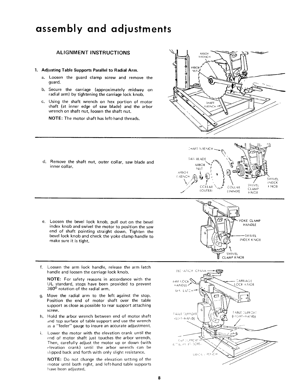
ALIGNMENT INSTRUCTIONS
1. Adjusting Table Supports Parallel to Radial Arm.
a. Loosen the guard clamp screw and remove the
guard.
b. Secure the carriage (approximately midway on
radial arm) by tightening the carriage lock knob.
c. Using the shaft wrench on hex portion of motor
shaft (at inner edge of saw blade) and the arbor
wrench on shaft nut, loosen the shaft nut.
NOTE: The motor shaft has left-hand threads.
d, Remove the shaft nut, outer collar, saw blade and
inner collar.
"- _1 J "
ARBOR\'
- ,,'_'__, . . \ _/" swtveu
• , ," iNDEX
",,, l< 2\ ....<
/COLLAR \ ,- _.'3 _.'1 EL b NOB
,., .,,_,_ __k_LLAR CLAMP
(OUTER} (INNER) _NOB
Loosen the bevel lock knob, pull out on the bevel
index knob and swivel the motor to position the saw
end of shaft pointing straight down. Tighten the
bevel lock knob and check the yoke clamp handle to
make sure it is tight.
f. Loosen the arm lock handle, release the arm latch
handle and loosen the carriage lock knob.
NOTE: For safety reasons in accordance with the
UL standard, stops have been provided to prevent
360 ° rotation of the radial arm.
g. Move the radial arm to the left against the stop.
Position the end of motor shaft over the table
support as close as possible to rear support attaching
screw.
h. Hold the arbor wrench between end of motor shaft
and top surface of table support and use the wrench
as a "feeler" gauge to insure an accurate adjustment.
i. Lower the motor with the elevation crank until the
end of motor shaft just touches the arbor wrench.
Then, carefully adjust the motor up or down (with
elevation crank) until the arbor wrench can be
sl_pped back and forth with only slight resistance.
NOTE: Do not change the elevation setting of the
motor untd both right, and left-hand table supports
have been adjusted.
_YOKE CLAMP
INDEX KNOB
EL[ ,ArlOr, CR__
k.
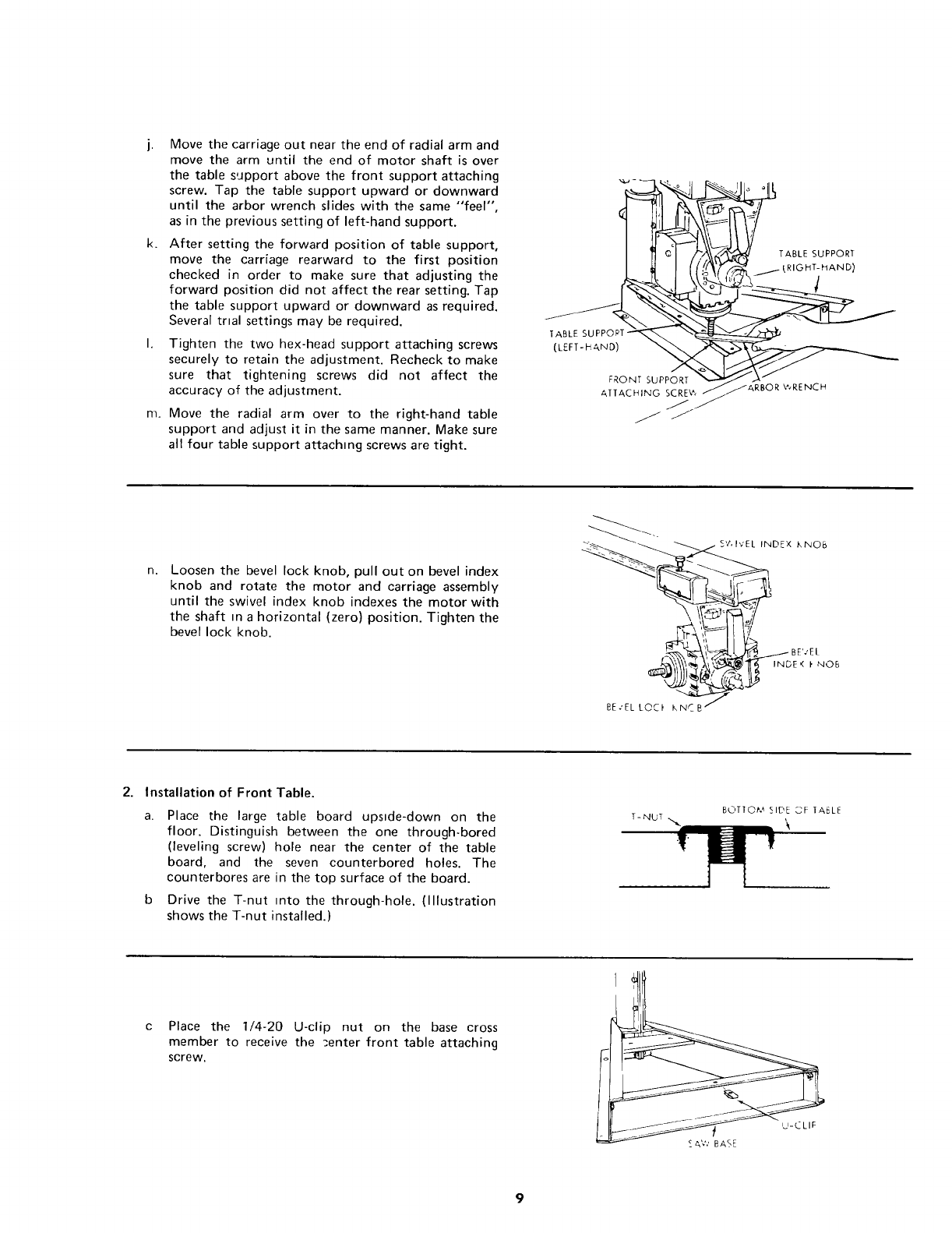
Move the carriage out near the end of radial arm and
move the arm until the end of motor shaft is over
the table support above the front support attaching
screw. Tap the table support upward or downward
until the arbor wrench slides with the same "'feel",
as in the previous setting of left-hand support.
After setting the forward position of table support,
move the carriage rearward to the first position
checked in order to make sure that adjusting the
forward position did not affect the rear setting. Tap
the table support upward or downward as required.
Several trial settings may be required.
Tighten the two hex-head support attaching screws
securely to retain the adjustment. Recheck to make
sure that tightening screws did not affect the
accuracy of the adjustment.
Move the radial arm over to the right-hand table
support and adjust it in the same manner. Make sure
all four table support attaching screws are tight.
TABLE SUPP©PT-
(LEFT-H AND)
FRONT SUPPORT
ATTACHING SCRE\ ^,
J
j J"
TABLE SUPPORT
RIGHT-HAND)
1
RBOR V_RENCH
n. Loosen the bevel lock knob, pull out on bevel index
knob and rotate the motor and carriage assembly
until the swivel index knob indexes the motor with
the shaft m a horizontal (zero) position. Tighten the
bevel lock knob.
S'7,1vEL INDEX KNOB
,( _' NOB
BE.'EL L©C_ KNC _'_-"_'-'-J
2. Installation of Front Table.
a. Place the large table board upside-down on the
floor. Distinguish between the one through-bored
(leveling screw) hole near the center of the table
board, and the seven counterbored holes. The
counterbores are in the top surface of the board.
Drive the T-nut into the through-hole. (Illustration
shows the T-nut installed.)
T-NUT BOTTOM SIDE SF TABLE
Place the 1/4-20 U-clip nut on the base cross
member to receive the _,enter front table attaching
screw.
assembly and adjustments
d. Place the large, front table board on the table
supports.
e. Align the counterbored holes with matching holes in
table supports.
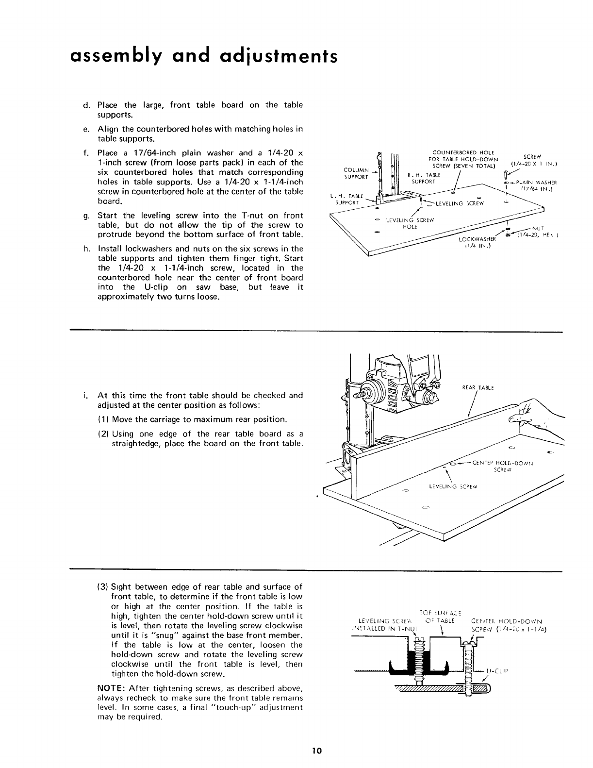
f. Place a 17/64-inch plain washer and a 1/4-20 x
1-inch screw (from loose parts pack) in each of the
six counterbored holes that match corresponding
holes in table supports. Use a 1/4-20 x 1-1/4-inch
screw in counterbored hole at the center of the table
board.
g.
h.
Start the leveling screw into the T-nut on front
table, but do not allow the tip of the screw to
protrude beyond the bottom surface of front table.
Install Iockwashers and nuts on the six screws in the
table supports and tighten them finger tight. Start
the 1/4-20 x 1-1/4-inch screw, located in the
counterbored hole near the center of front board
into the U-clip on saw base, but leave it
approximately two turns loose.
_lJ SCREW (SEVEN TOTAL) (I/4-20 X I IN.)
COLUMN .-..J1 HI/ ,' _-"_
SUPPORT-L] _LIl R.H. _A_E /U
_I 1111 SUPPORT I_._ PLAIN WASHER
o
o LEVELING SCRE_
\\ _/ LOCKWASHE" .......
,I/4 IN.}
At this time the front table should be checked and
adjusted at the center position as follows:
(1) Move the carriage to maximum rear position.
(2) Using one edge of the rear table board as a
straightedge, place the board on the front table.
REAR TABLE
_CENTEP HOLD-DO _N
SCPEW
(3) Sight between edge of rear table and surface of
front table, to determine if the front table is low
or high at the center position. If the table is
high, tighten the center hold-down screw untd it
is level, then rotate the leveling screw clockwise
until it is "snug" against the base front member.
If the table is low at the center, loosen the
hold-down screw and rotate the leveling screw
clockwise until the front table is level, then
tighten the hold-down screw.
NOTE: After tightening screws, as described above,
always recheck to make sure the front table remains
level. In some cases, a final "touch-up" adjustment
may be required.
TOF SURFACE
LEVELING SCRE'?,. OF TABLE
hNETALLED IN T-NUT \
CENTER HOLD-DO','_' N
SCRE,V (1/4-2C x 1-1/4)
U-CLIP
10
3. Squaring the Crosscut Travel.
a. Check to make sure the arm latch handle is securely
latched in the detent and the arm lock handle is still
tight.
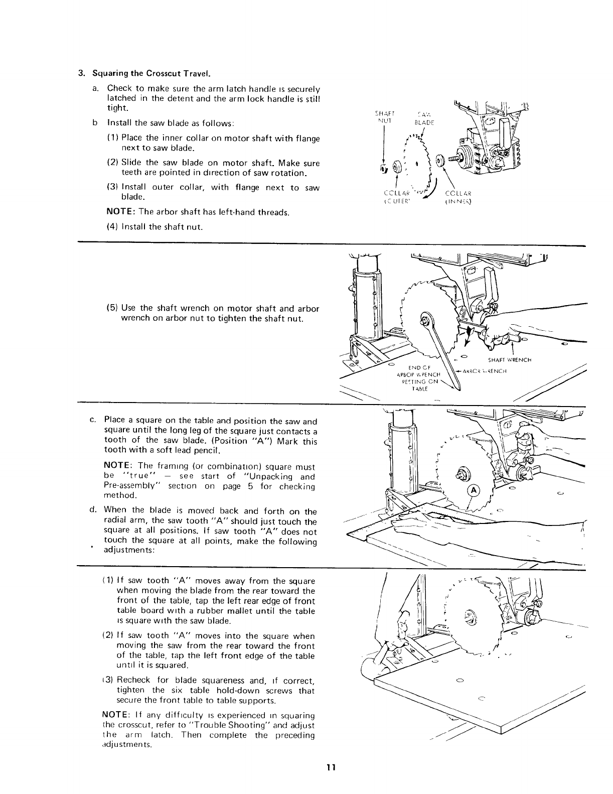
b Install the saw blade as follows:
(1) Place the inner collar on motor shaft with flange
next to saw blade.
(2) Slide the saw blade on motor shaft. Make sure
teeth are pointed in dwection of saw rotation.
(3) Install outer collar, with flange next to saw
blade.
NOTE: The arbor shaft has left-hand threads.
(4) Install the shaft nut.
SftAFT _ A'.', [_
_Uq BLADE
['._ UIER' (INN{F,)
C.
d.
(5) Use the shaft wrench on motor shaft and arbor
wrench on arbor nut to tighten the shaft nut.
E.DcF \\\ ...........
Place a square on the table and position the saw and
square until the long leg of the square just contacts a
tooth of the saw blade. (Position "A") Mark this
tooth with a soft lead pencil.
NOTE: The framing (or combination) square must
be "true" - see start of "Unpacking and
Pre-assembly" section on page 5 for checking
method.
When the blade is moved back and forth on the
radial arm, the saw tooth "A'" should just touch the
square at all positions. If saw tooth "A" does not
touch the square at all points, make the following
adjustments:
LLI¢
(1) If saw tooth "A" moves away from the square
when moving the blade from the rear toward the
front of the table, tap the left rear edge of front
table board with a rubber mallet until the table
is square w_th the saw blade.
(2) If saw tooth "A" moves into the square when
moving the saw from the rear toward the front
of the table, tap the left front edge of the table
until it is squared.
13) Recheck for blade squareness and, If correct,
tighten the six table hold-down screws that
secure the front table to table supports.
NOTE: If any difficulty is experienced _n squaring
the crosscut, refer to "Trouble Shooting" and adjust
the arm latch• Then complete the preceding
adjustments•
/
11
assembly and adjustments
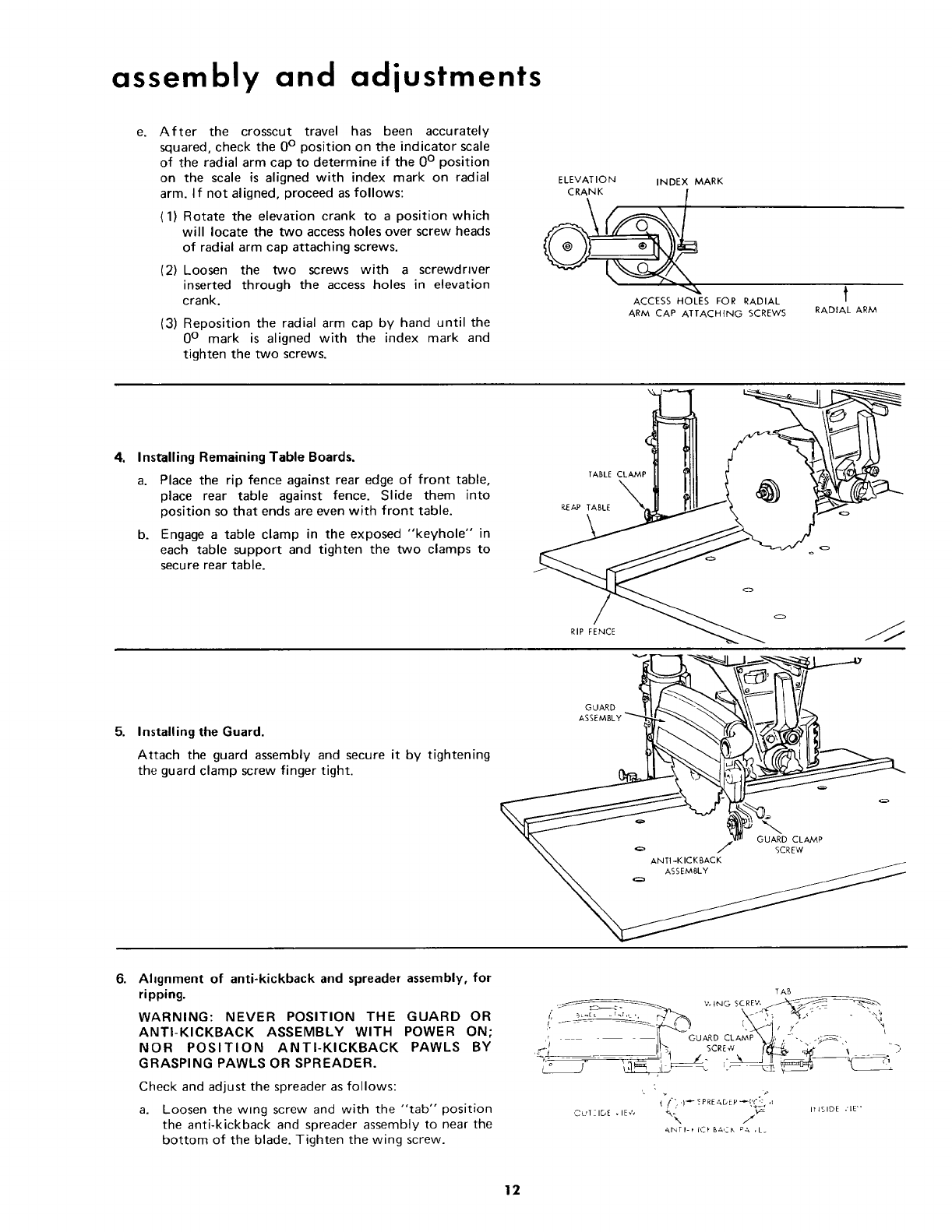
e. After the crosscut travel has been accurately
squared, check the 0° position on the indicator scale
of the radial arm cap to determine if the 0 ° position
on the scale is aligned with index mark on radial
arm. If not aligned, proceed as follows:
(1) Rotate the elevation crank to a position which
will locate the two access holes over screw heads
of radial arm cap attaching screws.
(2) Loosen the two screws with a screwdriver
inserted through the access holes in elevation
crank.
(3) Reposition the radial arm cap by hand until the
0 ° mark is aligned with the index mark and
tighten the two screws.
ELEVATION INDEX MARK
ACCESS HOLES FOR RADIAL
ARM CAP ATTACHING SCREWS
t
RADIAL ARM
4. Installing Remaining Table Boards.
5.
a. Place the rip fence against rear edge of front table,
place rear table against fence. Slide them into
position so that ends are even with front table.
b. Engage a table clamp in the exposed "keyhole" in
each table support and tighten the two clamps to
secure rear table.
.BACK
Installing the Guard.
Attach the guard assembly and secure it by tightening
the guard clamp screw finger tight.
6. Ahgnment of anti-kickback and spreader assembly, for
ripping.
WARNING: NEVER POSITION THE GUARD OR
ANTI-KICKBACK ASSEMBLY WITH POWER ON,
NOR POSITION ANTI-KICKBACK PAWLS BY
GRASPING PAWLS OR SPREADER.
Check and adjust the spreader as follows:
a. Loosen the wing screw and with the "tab" position
the anti-kickback and spreader assembly to near the
bottom of the blade. Tighten the wing screw.
TAB
I[ Gu,_oCL_MP\j,, ,-'-. .,=_,
t
v_ It JSIDE .' IE' '
_,NTI-_ ICk B_*'__, PA ,L_
12
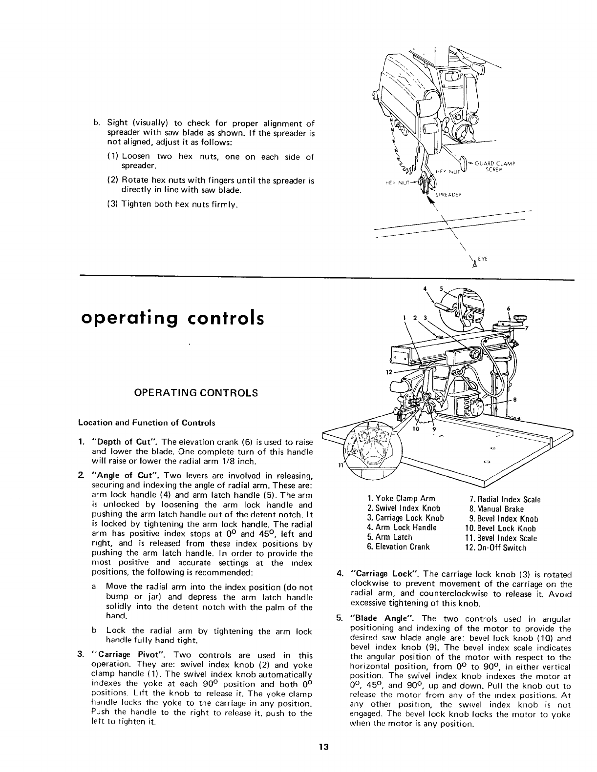
b. Sight (visually) to check for proper alignment of
spreader with saw blade as shown. If the spreader is
not aligned, adjust it as follows:
(1) Loosen two hex nuts, one on each side of
spreader.
(2) Rotate hex nuts with fingers until the spreader is
directly in line with saw blade.
(3) Tighten both hex nuts firmly.
_ OL'ARD CLAMP
SCREW
\\
\_EYE
operating controls
OPERATING CONTROLS
Location and Function of Controls
1°
Z
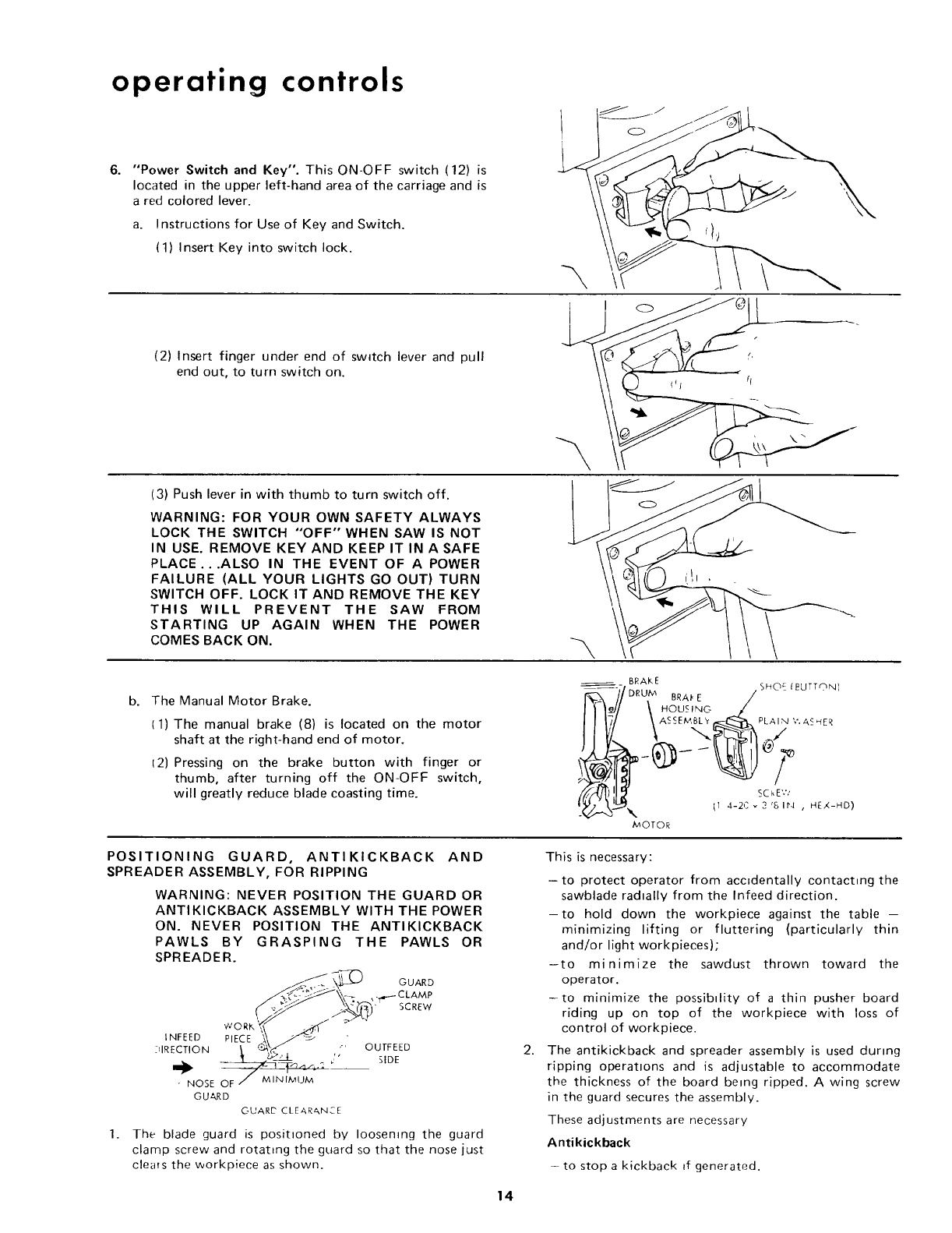
"Depth of Cut". The elevation crank (6) is used to raise
and lower the blade. One complete turn of this handle
will raise or lower the radial arm 1/8 inch.
"Angle of Cut". Two levers are involved in releasing,
securing and indexing the angle of radial arm. These are:
arm lock handle (4) and arm latch handle (5). The arm
is unlocked by loosening the arm lock handle and
pushing the arm latch handle out of the detent notch. It
is locked by tightening the arm lock handle. The radial
arm has positive index stops at 0 ° and 45 ° ,left and
right, and is released from these index positions by
pushing the arm latch handle. In order to provide the
most positive and accurate settings at the index
positions, the following is recommended:
Move the radial arm into the index position (do not
bump or jar) and depress the arm latch handle
solidly into the detent notch with the palm of the
hand.
b Lock the radial arm by tightening the arm lock
handle fully hand tight.
3. "Carriage Pivot". Two controls are used in this
operation. They are: swivel index knob (2) and yoke
clamp handle (1). The swivel index knob automatically
indexes the yoke at each 90 ° position and both 0 °
positions. Lift the knob to release it. The yoke clamp
handle locks the yoke to the carriage in any position.
Push the handle to the right to release it, push to the
left to tighten it.
4.
5.
4 5
I 2 3
1. Yoke Clamp Arm
2. Swivel Index Knob
3. Carriage Lock Knob
4. Arm Lock Handle
5. Arm Latch
6. Elevation Crank
7. Radial Index Scale
8. ManualBrake
9. BevelIndex Knob
10.BevelLock Knob
11.BevelIndexScale
12.On-Off Switch
"Carriage Lock". The carriage lock knob (3) is rotated
clockwise to prevent movement of the carriage on the
radial arm, and counterclockwise to release it. Avoad
excessive tightening of this knob.
"Blade Angle". The two controls used in angular
positioning and indexing of the motor to provide the
desired saw blade angle are: bevel lock knob (10) and
bevel index knob (9). The bevel index scale indicates
the angular position of the motor with respect to the
horizontal position, from 0 ° to 90 ° , in either vertical
position. The swivel index knob indexes the motor at
0 °, 45 ° , and 90 ° ,up and down. Pull the knob out to
release the motor from any of the tndex positions. At
any other position, the swwel index knob is not
engaged. The bevel lock knob locks the motor to yoke
when the motor is any position.
13
operating controls
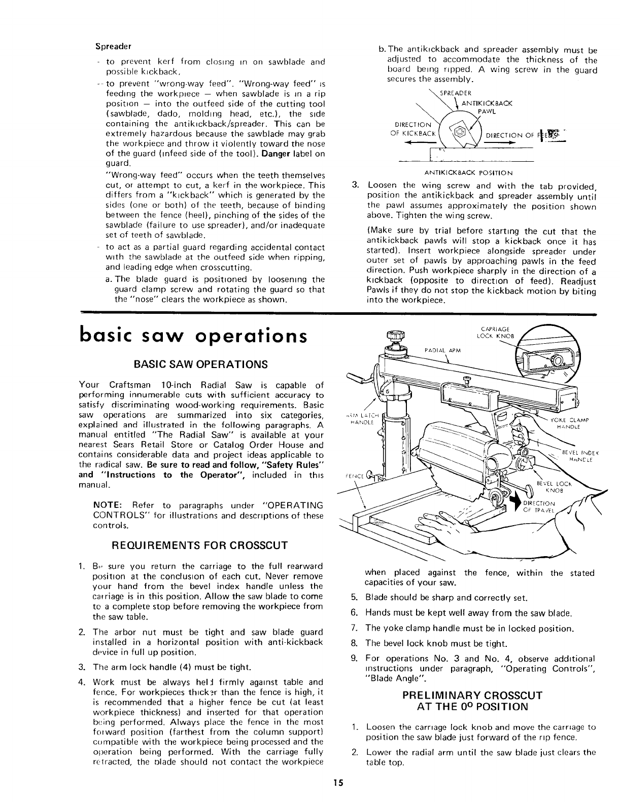
6. "Power Switch and Key". This ON-OFF switch (12) is
located in the upper left-hand area of the carriage and is
a red colored lever.
a. Instructions for Use of Key and Switch.
(1) Insert Key into switch lock.
(2) Insert finger under end of sw_tch lever and pull
end out, to turn switch on.
THIS WILL PREVENT THE
STARTING UP AGAIN WHEN
COMES BACK ON.
(3) Push lever in with thumb to turn switch off.
WARNING: FOR YOUR OWN SAFETY ALWAYS
LOCK THE SWITCH "'OFF" WHEN SAW IS NOT
IN USE. REMOVE KEY AND KEEP IT IN A SAFE
PLACE...ALSO IN THE EVENT OF A POWER
FAILURE (ALL YOUR LIGHTS GO OUT) TURN
SWITCH OFF. LOCK IT AND REMOVE THE KEY
SAW FROM
THE POWER
b. The Manual Motor Brake.
(1) The manual brake (8) is located on the motor
shaft at the right-hand end of motor.
12) Pressing on the brake button with finger or
thumb, after turning off the ON-OFF switch,
will greatly reduce blade coasting time.
BRAKE
_:. )/ RUM . SHOE _UTTON)
D,
11 BRA; _ E /
\.ou-<,NO,,
II 17/ \ASSEMBL_'_PLAI N'¢.A<_ER
II W_ "-.._-_ @_
I__J_l_\_ tl 4-2c _ 2 's ir_ , nEX-HO)
MOTOR
%
POSITIONING GUARD, ANTIKICKBACK AND
SPREADER ASSEMBLY, FOR RIPPING
WARNING: NEVER POSITION THE GUARD OR
ANTIKICKBACK ASSEMBLY WITH THE POWER
ON. NEVER POSITION THE ANTI KICKBACK
PAWLS BY GRASPING THE PAWLS OR
SPREADER.
GUARD
...,,,.-_CLAMP
i" SCREW
1.
INFEED PIECE
DIRECTION OUTFEED
¢" SIDE
- NOSE OF MINIMUM
GU&RD
GUARD CLEAbkNCE
The blade guard is positioned by Ioosemng the guard
clamp screw and rotating the guard so that the nose just
cleats the workpiece as shown.
This is necessary:
- to protect operator from accidentally contacting the
sawblade radially from the Infeed direction.
-to hold down the workpiece against the table --
minimizing lifting or fluttering {particularly thin
and/or light workpieces)"
-to minimize the sawdust thrown toward the
operator.
-to minimize the possibility of a thin pusher board
riding up on top of the workpiece with loss of
control of workpiece.
2. The antikickback and spreader assembly is used during
ripping operations and is adjustable to accommodate
the thickness of the board being ripped. A wing screw
in the guard secures the assembly.
These adjustments are necessary
Antikickback
-- to stop a kickback _f generated.
14
Spreader
to prevent kerf from closing in on sawblade and
possible Mckback,
- to prevent "wrong-way feed". "Wrong-way feed" is
feeding the workp_ece -- when sawblade is in a rip
posit_on - into the outfeed side of the cutting tool
(sawblade, dado, molding head, etc.), the side
containing the antiMckbacklspreader. This can be
extremely hazardous because the sawblade may grab
the workpiece and throw it violently toward the nose
of the guard (mfeed side of the tool). Danger label on
guard.
"Wrong-way feed" occurs when the teeth themselves
cut, or attempt to cut, a kerf in the workpiece. This
differs from a "kickback" which is generated by the
sides (one or both) of the teeth, because of binding
between the fence (heel), pinching of the sides of the
sawblade (failure to use spreader), and/or inadequate
set of teeth of sawblade.
to act as a partial guard regarding accidental contact
with the sawblade at the outfeed side when ripping,
and leading edge when crosscutting.
a. The blade guard is positioned by loosening the
guard clamp screw and rotating the guard so that
the "nose" clears the workpiece as shown.
3.
b. The antikpckback and spreader assembly must be
adjusted to accommodate the thickness of the
board being ripped. A wing screw in the guard
secures the assembly.
READER
ANTIKICKBACK
PAWL
OF KICKBACK t _ \\ ]DIRECTION
oFFf!
ANTIKICKBACK POSITION
Loosen the wing screw and with the tab provided,
position the antikickback and spreader assembly until
the pawl assumes approximately the position shown
above. Tighten the wing screw.
(Make sure by trial before starting the cut that the
antikickback pawls will stop a kickback once it has
started). Insert workpiece alongside spreader under
outer set of pawls by approaching pawls in the feed
direction. Push workpiece sharply in the direction of a
kickback (opposite to direction of feed). Readjust
Pawls if they do not stop the kickback motion by biting
into the workpiece.
basic saw operations
BASIC SAW OPERATIONS
Your Craftsman 10-inch Radial Saw is capable of
performing innumerable cuts with sufficient accuracy to
satisfy discriminating wood-working requirements. Basic
saw operations are summarized into six categories,
explained and illustrated in the following paragraphs. A
manual entitled "The Radial Saw" is available at your
nearest Sears Retail Store or Catalog Order House and
contains considerable data and project ideas applicable to
the radical saw. Be sure to read and follow, "Safety Rules'"
and "Instructions to the Operator", included in this
manual.
NOTE: Refer to paragraphs under "OPERATING
CONTROLS" for illustrations and descriptions of these
controls.
REQUIREMENTS FOR CROSSCUT
1. B_ sure you return the carriage to the full rearward
position at the conclusion of each cut. Never remove
your hand from the bevel index handle unless the
carriage is in this position. Allow the saw blade to come
to a complete stop before removing the workpiece from
the saw table.
2. The arbor nut must be tight and saw blade guard
installed in a horizontal position with anti-kickback
device in full up position.
3. The arm lock handle (4) must be tight.
4. Work must be always hel:l firmly against table and
fence. For workpieces thlck_,r than the fence is high, it
is recommended that a higher fence be cut (at least
workpiece thickness) and inserted for that operation
being performed. Always place the fence in the most
forward position (farthest from the column support)
compatible with the workpiece being processed and the
operation being performed. With the carriage fully
re;racted, the t)lade should not contact the workpiece
CAPRIAGE
LOCK KNOB
PADIAL APM
FEr4CE !
\\
5.
6.
7.
8.
9.
when placed against the fence, within the stated
capacities of your saw.
Blade should be sharp and correctly set.
Hands must be kept well away from the saw blade.
The yoke clamp handle must be in locked position.
The bevel lock knob must be tight.
For operations No. 3 and No. 4, observe additional
instructions under paragraph, "Operating Controls",
"Blade Angle".
PRELIMINARY CROSSCUT
AT THE 0° POSITION
1. Loosen the carnage lock knob and move the carnage to
position the saw blade just forward of the rip fence.
2. Lower the radial arm until the saw blade just clears the
table top.
15
basic saw operations
3. Tighten the carnage lock knob.
CAUTION: Before making the cut, make sure the arm
latch handle is fully engaged in the detent notch.
4. Plug in the power cord (if not already connected.)
5. Insert the safety lock key and pull the switch lever to
"ON" position.
6. Lower the radial arm, by rotating the elevation crank,
untd the saw blade cuts into the table top surface to a
depth of approximately 1/32 inch.
NOTE: Some owners prefer to cover the saw table with
thin plywood, tacking it outside of saw travel area in
order to protect the table surface.
7. Operate the saw in the same manner as shown and
complete the blade clearance groove in the table rip
fence as follows:
a.
b.
Loosen the carriage lock knob and slowly pull the
carriage out to the extreme end of its travel.
Push the carriage slowly rearward to the extreme
end of the travel. This stroke will cut through the
rip fence.
c. Push the switch to "OFF" position.
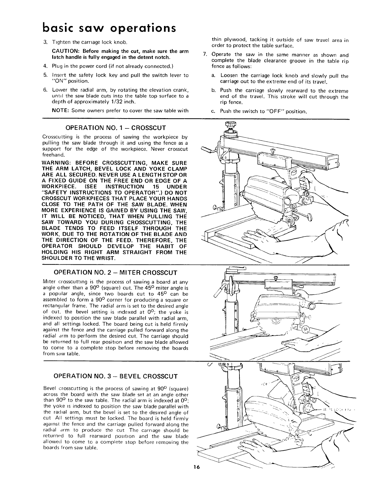
OPERATION NO. 1 -CROSSCUT
Crosscutting is the process of sawing the workpiece by
pulling the saw blade through it and using the fence as a
support for the edge of the workpiece. Never crosscut
freehand.
WARNING: BEFORE CROSSCUTTING, MAKE SURE
THE ARM LATCH, BEVEL LOCK AND YOKE CLAMP
ARE ALL SECURED. NEVER USE A LENGTH STOP OR
A FIXED GUIDE ON THE FREE END OR EDGE OF A
WORKPIECE. (SEE INSTRUCTION 15 UNDER
"SAFETY INSTRUCTIONS TO OPERATOR".) DO NOT
CROSSCUT WORKPIECES THAT PLACE YOUR HANDS
CLOSE TO THE PATH OF THE SAW BLADE. WHEN
MORE EXPERIENCE IS GAINED BY USING THE SAW,
IT WILL BE NOTICED, THAT WHEN PULLING THE
SAW TOWARD YOU DURING CROSSCUTTING, THE
BLADE TENDS TO FEED ITSELF THROUGH THE
WORK, DUE TO THE ROTATION OF THE BLADE AND
THE DIRECTION OF THE FEED. THEREFORE, THE
OPERATOR SHOULD DEVELOP THE HABIT OF
HOLDING HIS RIGHT ARM STRAIGHT FROM THE
SHOULDER TO THE WRIST.
OPERATION NO. 2 - MITER CROSSCUT
Mtter crosscuttmg is the process of sawing a board at any
angle other than a 90 ° (square) cut. The 45 ° miter angle is
a popular angle, since two boards cut to 45 ° can be
assembled to form a 90 ° corner for producing a square or
rectangular frame. The radial arm is set to the desired angle
of cut, the bevel setting is indexed at 0°; the yoke is
indexed to posttion the saw blade parallel with radial arm,
and all settings locked. The board being cut is held firmly
against the fence and the carriage pulled forward along the
radial arm to perform the desired cut. The carriage should
be returned to full rear position and the saw blade allowed
to come to a complete stop before removing the boards
from saw table,
OPERATION NO. 3 - BEVEL CROSSCUT
Bevel crosscutting is the process of sawing at 90 ° (square)
across the board with the saw blade set at an angle other
than 90 ° to the saw table. The radial arm is indexed at 0°;
the yoke =s indexed to position the saw blade parallel with
the ra(hal arm, but the bevel is set to the des=red angle of
cut All settings must be locked. The board is held firmly
against the fence and the carriage pulled forward along the
radial drm to produce the cut Tile carnage should be
returned to full rearward posmon and the saw blade
allowed to come to a complete stop before removing the
boards from saw table.
16
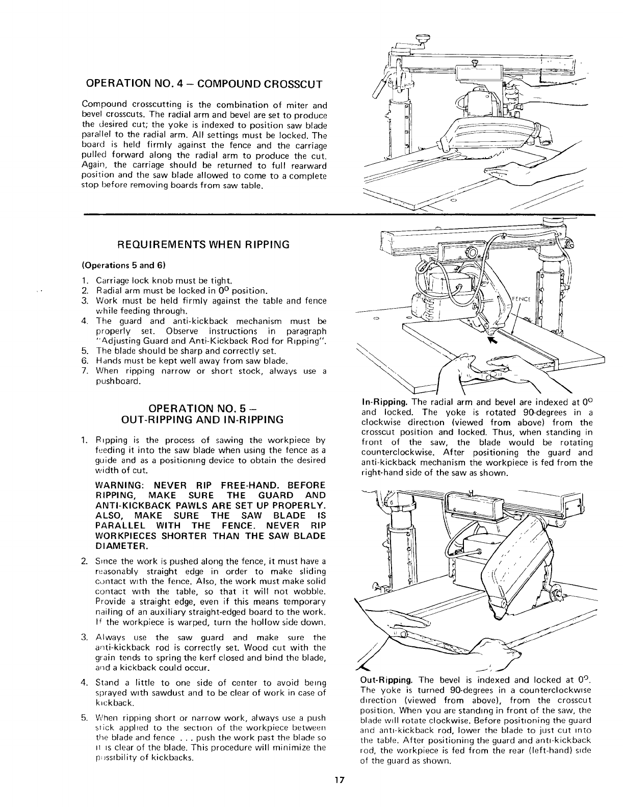
OPERATION NO. 4 - COMPOUND CROSSCUT
Compound crosscutting is the combination of miter and
bevel crosscuts. The radial arm and bevel are set to produce
the desired cut; the yoke is indexed to position saw blade
parallel to the radial arm. All settings must be locked. The
board is held firmly against the fence and the carriage
pulled forward along the radial arm to produce the cut.
Again, the carriage should be returned to full rearward
position and the saw blade allowed to come to a complete
stop before removing boards from saw table.
REQUIREMENTS WHEN RIPPING
(Operations 5 and 6)
1. Carriage lock knob must be tight.
2. Radial arm must be locked in 0 ° position.
3. Work must be held firmly against the table and fence
while feeding through.
4. The guard and anti-kickback mechanism must be
properly set. Observe instructions in paragraph
"Adjusting Guard and Anti-Kickback Rod for Ripping".
5. The blade should be sharp and correctly set.
6. Hands must be kept well away from saw blade.
7. When ripping narrow or short stock, always use a
pushboard.
1.
OPERATION NO. 5 -
OUT-RIPPING AND IN-RIPPING
R_pping is the process of sawing the workpiece by
feeding it into the saw blade when using the fence as a
guide and as a positioning device to obtain the desired
width of cut.
WARNING: NEVER RIP FREE-HAND. BEFORE
RIPPING, MAKE SURE THE GUARD AND
ANTI-KICKBACK PAWLS ARE SET UP PROPERLY.
ALSO, MAKE SURE THE SAW BLADE IS
PARALLEL WITH THE FENCE. NEVER RIP
WORKPIECES SHORTER THAN THE SAW BLADE
DIAMETER.
2. Since the work is pushed along the fence, it must have a
reasonably straight edge in order to make sliding
contact with the fence. Also, the work must make solid
contact w_th the table, so that it will not wobble.
Provide a straight edge, even if this means temporary
nailing of an auxiliary straight-edged board to the work.
If the workpiece is warped, turn the hollow side down.
3. Always use the saw guard and make sure the
anti-kickback rod is correctly set. Wood cut with the
grain tends to spring the kerf closed and bind the blade,
a_ld a kickback could occur.
4.
5.
Stand a little to one side of center to avoid being
sprayed w_th sawdust and to be clear of work in case of
kickback.
When ripping short or narrow work, always use a push
stick applied to the sectton of the workpiece between
the blade and fence . .. push the work past the blade so
n _s clear of the blade. This procedure will minimize the
p:_ssrbility of kickbacks.
In-Ripping. The radial arm and bevel are indexed at 0 °
and locked. The yoke is rotated 90-degrees in a
clockwise directton (viewed from above) from the
crosscut position and locked. Thus, when standing in
front of the saw, the blade would be rotating
counterclockwise. After positioning the guard and
anti-kickback mechanism the workpiece is fed from the
right-hand side of the saw as shown.
Out-Ripping. The bevel is indexed and locked at 0 °.
The yoke is turned 90-degrees in a counterclockwise
d_rection (viewed from above), from the crosscut
position. When you are standing in front of the saw, the
blade wtll rotate clockwise. Before positioning the guard
and ant_-kickback rod, lower the blade to just cut into
tile table. After positioning the guard and anti-kickback
rod, the workpiece is fed from the rear (left-hand) s_de
of the guard as shown.
17
basic saw operations
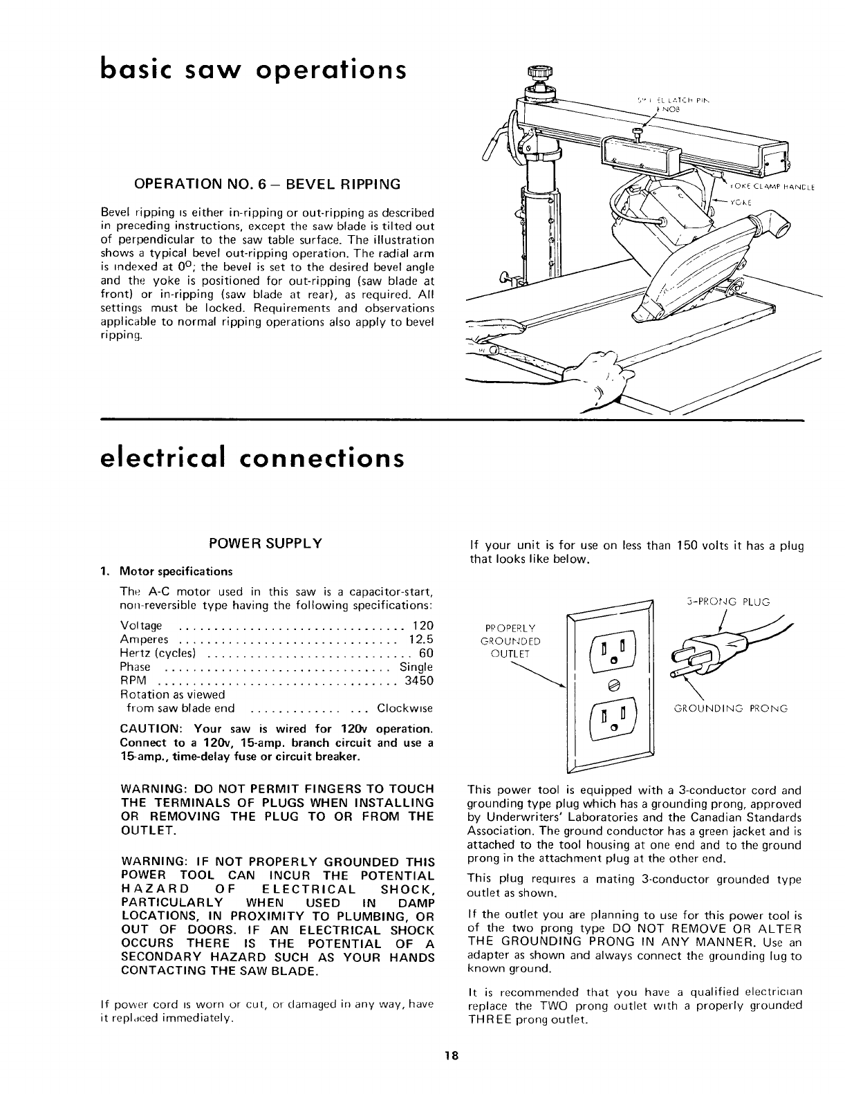
OPERATION NO. 6- BEVEL RIPPING
Bevel ripping Is either in-ripping or out-ripping as described
in preceding instructions, except the saw blade is tilted out
of perpendicular to the saw table surface. The illustration
shows a typical bevel out-ripping operation. The radial arm
is indexed at 0°; the bevel is set to the desired bevel angle
and the yoke is positioned for out-ripping (saw blade at
front) or in-ripping (saw blade at rear), as required. All
settings must be locked. Requirements and observations
applicable to normal ripping operations also apply to bevel
ripping.
electrical connections
1.
POWER SUPPLY
Motor specifications
The A-C motor used in this saw is a capacitor-start,
non-reversible type having the following specifications:
Voltage ................................ 120
Amperes ............................... 12.5
Hertz (cycles) ............................. 60
Phase ................................ Single
RPM .................................. 3450
Rotation as viewed
from saw blade end ................ Clockwise
CAUTION: Your saw is wired for 120v operation.
Connect to a 120v, 15-amp. branch circuit and use a
l_amp., time-delay fuse or circuit breaker.
WARNING: DO NOT PERMIT FINGERS TO TOUCH
THE TERMINALS OF PLUGS WHEN INSTALLING
OR REMOVING THE PLUG TO OR FROM THE
OUTLET.
WARNING: IF NOT PROPERLY GROUNDED THIS
POWER TOOL CAN INCUR THE POTENTIAL
HAZARD OF ELECTRICAL SHOCK,
PARTICULARLY WHEN USED IN DAMP
LOCATIONS, IN PROXIMITY TO PLUMBING, OR
OUT OF DOORS. IF AN ELECTRICAL SHOCK
OCCURS THERE IS THE POTENTIAL OF A
SECONDARY HAZARD SUCH AS YOUR HANDS
CONTACTING THE SAW BLADE.
If power cord ts worn or cut, oi- clamaged in any way, have
it replaced immediately.
If your unit is for use on less than 150 volts it has a plug
that looks like below.
PPOPERLY II
3-PRONG PLdG
GROUNDING PRONG
This power tool is equipped with a 3-conductor cord and
grounding type plug which has a grounding prong, approved
by Underwriters' Laboratories and the Canadian Standards
Association. The ground conductor has a green jacket and is
attached to the tool housing at one end and to the ground
prong in the attachment plug at the other end.
This plug requires a mating 3-conductor grounded type
outlet as shown.
If the outlet you are planning to use for this power tool is
of the two prong type DO NOT REMOVE OR ALTER
THE GROUNDING PRONG IN ANY MANNER. Use an
adapter as shown and always connect the grounding lug to
known ground.
It is recommended that you have a qualified electrictan
replace the TWO prong outlet w_th a properly grounded
THREE prong outlet.
18
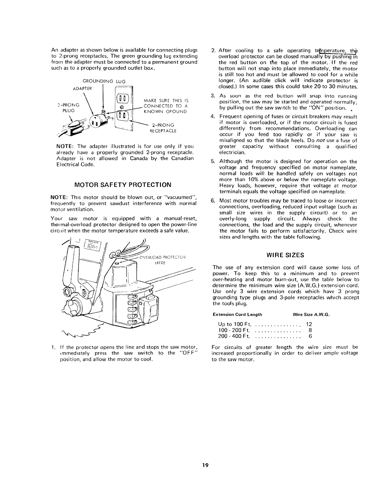
An adapter as shown below is available for connecting plugs
to 2-prong receptacles. The green grounding lug extending
from the adapter must be connected to a permanent ground
such as to a properly grounded outlet box.
GROUNDING LUG
ADAPTER__ '_I_.._.,,,_
MAKE SURE THIS IS
?-PRONG CONNECTED TO A
PLUG _ ._ KNOWN GPOUND
RECEPTACLE
NOTE: The adapter illustrated is for use only if you
already have a properly grounded 2-prong receptacle.
Adapter is not allowed in Canada by the Canadian
Electrical Code.
MOTOR SAFETY PROTECTION
NOTE: This motor should be blown out, or "vacuumed",
frequently to prevent sawdust interference with normal
motor ventilation.
Your saw motor is equipped with a manual-reset,
thermal-overload protector designed to open the power-line
circait when the motor temperature exceeds a safe value.
2.
3.
4.
After cooling to a safe operating tenure, thje
overload protector can be closed manually by pu's'hingT-n
the red button on the top of the motor. If the red
button will not snap into place immediately, the motor
is still too hot and must be allowed to cool for a while
longer. (An audible click will indicate protector is
closed.) In some cases this could take 20 to 30 minutes.
As soon as the red button will snap into running
position, the saw may be started and operated normally,
by pulling out the saw switch to the "'ON" position. ,
Frequent opening of fuses or circuit breakers may result
if motor is overloaded, or if the motor circuit is fused
differently from recommendations. Overloading can
occur if you feed too rapidly or if your saw is
misaligned so that the blade heels. Do not use a fuse of
greater capacity without consulting a qualified
electrician.
5. Although the motor is designed for operation on the
voltage and frequency specified on motor nameplate,
normal loads will be handled safely on voltages not
more than 10% above or below the nameplate voltage.
Heavy loads, however, require that voltage at motor
terminals equals the voltage specified on nameplate.
6. Most motor troubles may be traced to loose or incorrect
connections, overloading, reduced input voltage (such as
small size wires in the supply circuit) or to an
overly-long supply circuit. Always check the
connections, the load and the supply circuit, whenever
the motor fails to perform satisfactorily. Check wire
sizes and lengths with the table following.
OVERLOAD PROTECTO_
LRED)
1. If the protector opens the line and stops the saw motor,
.mmedlately press the saw switch to the "OFF"
position, and allow the motor to cool.
WIRE SIZES
The use of any extension cord will cause some loss of
power. To keep this to a minimum and to prevent
over-heating and motor burn-out, use the table below to
determine the minimum wire size (A.W.G.) extension cord.
Use only 3 wire extension cords which have 3 prong
grounding type plugs and 3-pole receptacles which accept
the tools plug.
Extension Cord Length Wire Size A.W.G.
Up to 100Ft ................ 12
100-200 Ft ................ 8
200-400 Ft ................ 6
For circuits of greater length the wire size must be
increased proportionally in order to deliver ample voltage
to the saw motor.
19
trouble-shooting
TROUBLE-SHOOTING
Even though the finest materials and precision
workmanship have been incorporated into your Craftsman
saw, it is reasonable to expect some wear after long periods
of use. Adjustment facilities have been built into the saw to
compensate for this wear. Looseness due to wear, rough
handling, or improper adjustments will usually be indicated
by reduced accuracy, or the inability of the saw to perform
as intended, The usual operating "troubles" are listed in the
following paragraphs with necessary corrections described
and illustrated.
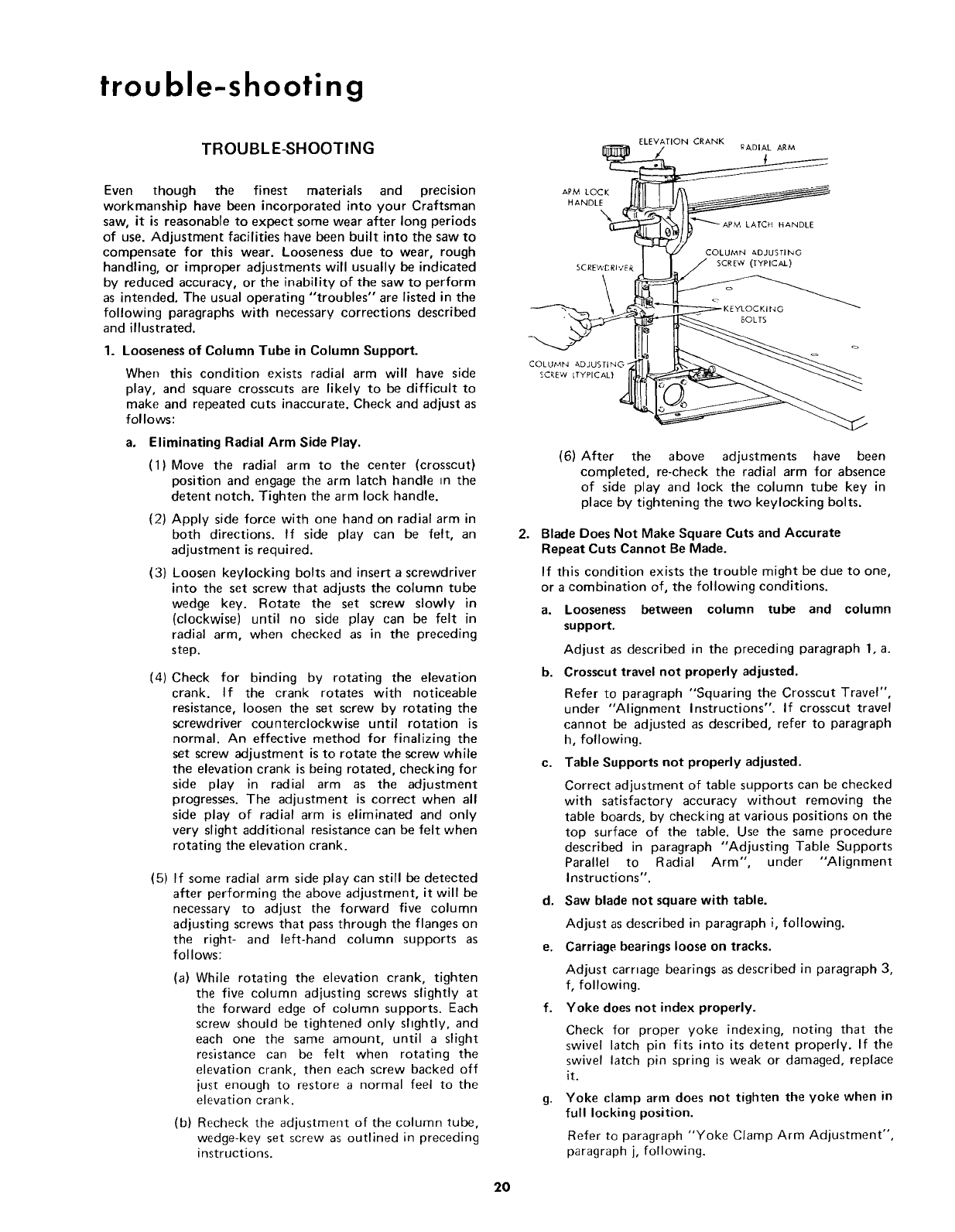
1. Looseness of Column Tube in Column Support.
When this condition exists radial arm will have side
play, and square crosscuts are likely to be difficult to
make and repeated cuts inaccurate. Check and adjust as
follows:
Eliminating Radial Arm Side Play.
(1) Move the radial arm to the center (crosscut)
position and engage the arm latch handle in the
detent notch. Tighten the arm lock handle.
(2) Apply side force with one hand on radial arm in
both directions. If side play can be felt, an
adjustment is required.
(3) Loosen keylocking bolts and insert a screwdriver
into the set screw that adjusts the column tube
wedge key. Rotate the set screw slowly in
(clockwise) until no side play can be felt in
radial arm, when checked as in the preceding
step.
(4)
a,
Check for binding by rotating the elevation
crank. If the crank rotates with noticeable
resistance, loosen the set screw by rotating the
screwdriver counterclockwise until rotation is
normal. An effective method for finalizing the
set screw adjustment is to rotate the screw while
the elevation crank is being rotated, checking for
side play in radial arm as the adjustment
progresses. The adjustment is correct when all
side play of radial arm is eliminated and only
very slight additional resistance can be felt when
rotating the elevation crank.
(5) If some radial arm side play can still be detected
after performing the above adjustment, it will be
necessary to adjust the forward five column
adjusting screws that pass through the flanges on
the right- and left-hand column supports as
follows:
(a) While rotating the elevation crank, tighten
the five column adjusting screws slightly at
the forward edge of column supports. Each
screw should be tightened only slightly, and
each one the same amount, until a slight
resistance can be felt when rotating the
elevation crank, then each screw backed off
just enough to restore a normal feel to the
elevation crank.
(b) Recheck the adjustment of the column tube,
wedge-key set screw as outlined in preceding
instructions.
ELEVATION CRANK
<_-RE V ITYPICAL) _ ___._
(6) After the above adjustments have been
completed, re-check the radial arm for absence
of side play and lock the column tube key in
place by tightening the two keylocking bolts.
2. Blade Does Not Make Square Cuts and Accurate
Repeat Cuts Cannot Be Made.
If this condition exists the trouble might be due to one,
or a combination of, the following conditions.
a. Looseness between column tube and column
support.
Adjust as described in the preceding paragraph 1, a.
b. Crosscut travel not properly adjusted.
Refer to paragraph "Squaring the Crosscut Travel",
under "Alignment Instructions". If crosscut travel
cannot be adjusted as described, refer to paragraph
h, following.
c. Table Supports not properly adjusted.
Correct adjustment of table supports can be checked
with satisfactory accuracy without removing the
table boards, by checking at various positions on the
top surface of the table. Use the same procedure
described in paragraph "Adjusting Table Supports
Parallel to Radial Arm", under "Alignment
Instructions".
d. Saw blade not square with table.
Adjust as described in paragraph i, following.
e. Carriage bearings loose on tracks.
Adjust carriage bearings as described in paragraph 3,
f, following.
f. Yoke does not index properly.
Check for proper yoke indexing, noting that the
swivel latch pin fits into its detent properly. If the
swivel latch pin spring is weak or damaged, replace
it.
g. Yoke clamp arm does not tighten the yoke when in
full locking position.
Refer to paragraph "Yoke Clamp Arm Adjustment",
paragraph j, following.
20
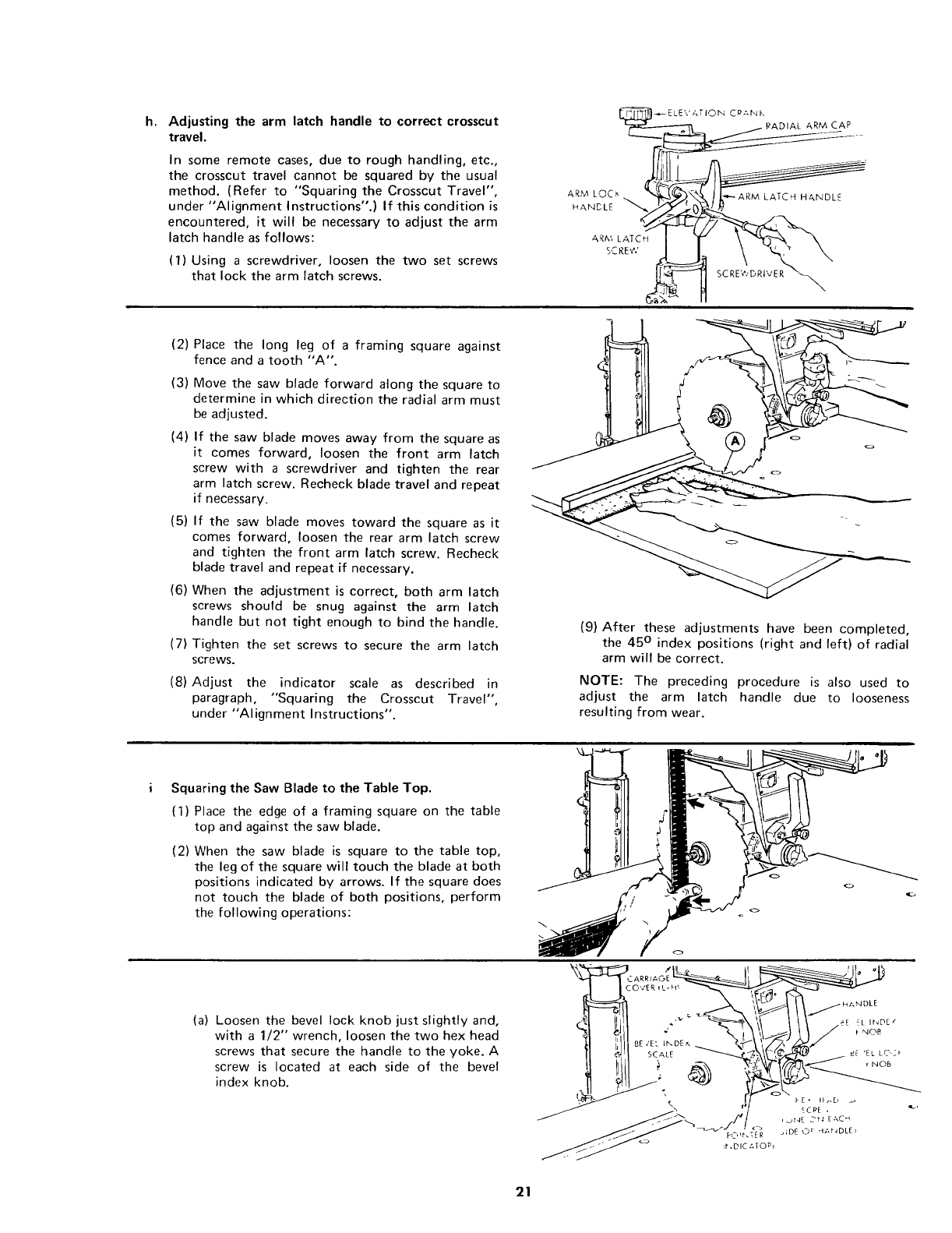
h. Adjustingthearmlatchhandleto correctcrosscut
travel.
In some remote cases, due to rough handling, etc.,
the crosscut travel cannot be squared by the usual
method. (Refer to "Squaring the Crosscut Travel",
under "Alignment Instructions".) If this condition is
encountered, it will be necessary to adjust the arm
latch handle as follows:
(1) Using a screwdriver, loosen the two set screws
that lock the arm latch screws.
ARM L,OC_, LATCH HANDLE
HANDLE
ARM LATCH
SCREV.'
SC RE'€,'DRIVE R _
(2)
(3)
(4)
(5)
(6)
(7)
(8)
Place the long leg of a framing square against
fence and a tooth "A".
Move the saw blade forward along the square to
determine in which direction the radial arm must
be adjusted.
If the saw blade moves away from the square as
it comes forward, loosen the front arm latch
screw with a screwdriver and tighten the rear
arm latch screw. Recheck blade travel and repeat
if necessary.
If the saw blade moves toward the square as it
comes forward, loosen the rear arm latch screw
and tighten the front arm latch screw. Recheck
blade travel and repeat if necessary.
When the adjustment is correct, both arm latch
screws should be snug against the arm latch
handle but not tight enough to bind the handle.
Tighten the set screws to secure the arm latch
screws.
Adjust the indicator scale as described in
paragraph, "Squaring the Crosscut Travel",
under "Alignment Instructions".
(9) After these adjustments have been completed,
the 45 ° index positions (right and left) of radial
arm will be correct.
NOTE: The preceding procedure is also used to
adjust the arm latch handle due to looseness
resulting from wear.
Squaring the Saw Blade to the Table Top.
(1) Place the edge of a framing square on the table
top and against the saw blade.
(2) When the saw blade is square to the table top,
the leg of the square will touch the blade at both
positions indicated by arrows. If the square does
not touch the blade of both positions, perform
the following operations:
(a) Loosen the bevel lock knob just slightly and,
with a 1/2" wrench, loosen the two hex head
screws that secure the handle to the yoke. A
screw is located at each side of the bevel
index knob.
I
21
trouble-shooting
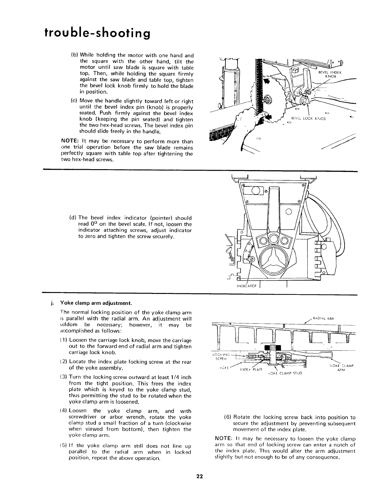
(b) While holding the motor with one hand and
the square with the other hand, tilt the
motor until saw blade is square with table
top. Then, while holding the square firmly
against the saw blade and table top, tighten
the bevel lock knob firmly to hold the blade
in position.
(c) Move the handle slightly toward left or right
until the bevel index pin (knob) is properly
seated. Push firmly against the bevel index
knob (keeping the pin seated) and tighten
the two hex-head screws. The bevel index pin
should slide freely in the handle.
NOTE: It may be necessary to perform more than
one trial operation before the saw blade remains
perfectly square with table top after tightening the
two hex-head screws.
BEVEL INDEX
KNOB
(d) The bevel index indicator (pointer) should
read 0 ° on the bevel scale. If not, loosen the
indicator attaching screws, adjust indicator
to zero and tighten the screw securely.
j. Yoke clamp arm adjustment.
The normal locking position of the yoke clamp arm
ts parallel with the radial arm. An adjustment will
seldom be necessary; however, it may be
accomplished as follows:
(1) Loosen the carriage lock knob, move the carriage
out to the forward end of radial arm and tighten
carriage lock knob.
t2)
(3)
_4)
Locate the index plate locking screw at the rear
of the yoke assembly.
Turn the locking screw outward at least 1/4 inch
from the tight position. This frees the index
plate which is keyed to the yoke clamp stud,
thus permitting the stud to be rotated when the
yoke clamp arm is loosened.
Loosen the yoke clamp arm, and wtth
screwdriver or arbor wrench, rotate the yoke
clamp stud a small fraction of a turn (clockwise
when viewed from bottom), then tighten the
yoke clamp arm.
(5) If the yoke clamp arm sttll does not line up
parallel to the radtal arm when in locked
position, repeat the above operation.
,_ RADI,&L ARA._
,©I<E CLAMP STLID
(6) Rotate the locking screw back into position to
secure the adjustment by preventing subsequent
movement of the mdex plate.
NOTE: It may be necessary to loosen the yoke clamp
arm so that end of locking screw can enter a notch of
the index plate. This would alter the arm adjustment
slightly but not enough to be of any consequence.
22
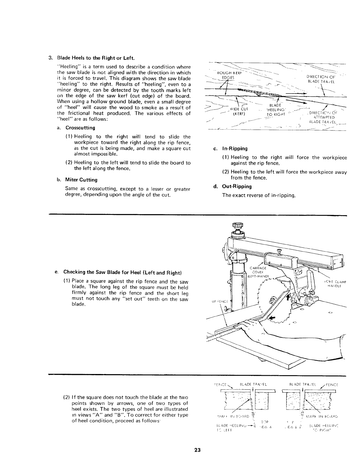
3. Blade Heels to the Right or Left.
"Heeling" is a term used to describe a condition where
the saw blade is not aligned with the direction in which
it is forced to travel. This diagram shows the saw blade
"heeling" to the right. Results of "heeling", even to a
minor degree, can be detected by the tooth marks left
on the edge of the saw kerf (cut edge) of the board.
When using a hollow ground blade, even a small degree
of "heel" will cause the wood to smoke as a result of
the frictional heat produced. The various effects of
"heel" are as follows:
a. Crosscutting
(1) Heeling to the right will tend to slide the
workpiece toward the right along the rip fence,
as the cut is being made, and make a square cut
almost impossible.
(2) Heeling to the left will tend to slide the board to
the left along the fence.
b. Miter Cutting
Same as crosscutting, except to a lesser or greater
degree, depending upon the angle of the cut.
rouo. KERR- --_-_ _...... --_-_
.... _ EDGES _ DIRECTION OF "?"
_ - "-__ BLADE TRA.'EL
WIDE CtJT 'HEELING' _ _ _z . ._
t KERF) TO RIGHT -_- " DIRECTIC'r.' OF
, -_ __c-- r ATTEMPTED
c. In-Ripping
(1) Heeling to the right will force the workpiece
against the rip fence.
(2) Heeling to the left will force the workpiece away
from the fence.
d. Out-Ripping
The exact reverse of in-ripping.
e. Checking the Saw Blade for Heel (Left and Right)
(1) Place a square against the rip fence and the saw
blade. The long leg of the square must be held
firmly against the rip fence and the short leg
must not touch any "set out" teeth on the saw
blade.
(2) If the square does not touch the blade at the two
points shown by arrows, one of two types of
heel exists. The two types of heel are illustrated
in views"A" and "B". To correct for either type
of heel condition, proceed as follows-
_EFJCE ._ BLADE TPA','EL
J
l'_'P
E,L_DE '_[ELlr_c_'_ll 'IE;'..t,
TC LEF[
BLADE TPA.'EL /FENCE
:_'} \
T p
BLADE mELLIr'JC
_C, P I ¢_ H _
23
trouble-shooting
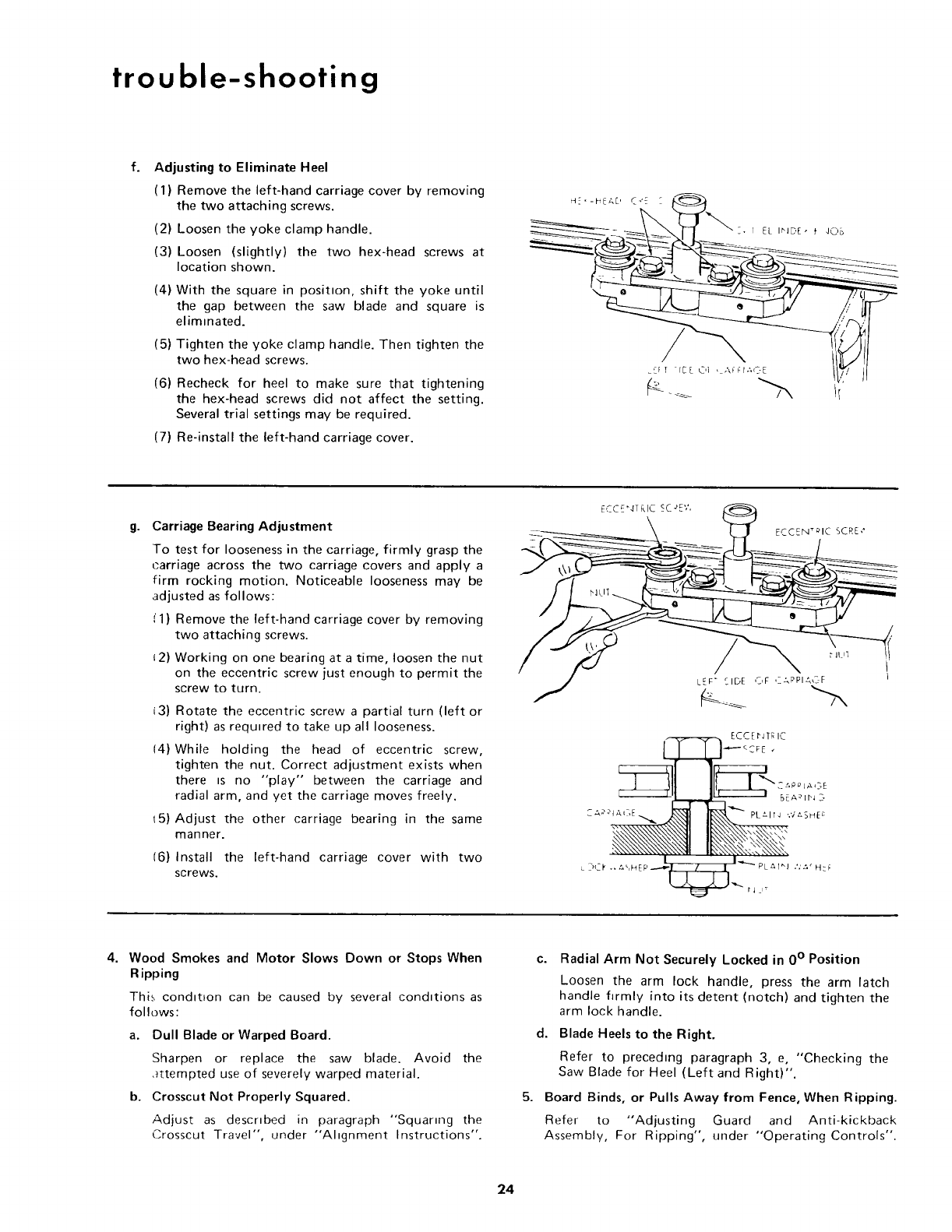
f. Adjusting to Eliminate Heel
(1) Remove the left-hand carriage cover by removing
the two attaching screws.
(2) Loosen the yoke clamp handle.
(3) Loosen (slightly) the two hex-head screws at
location shown.
(4) With the square in positron, shift the yoke until
the gap between the saw blade and square is
elimmated.
(5) Tighten the yoke clamp handle. Then tighten the
two hex-head screws.
(6) Recheck for heel to make sure that tightening
the hex-head screws did not affect the setting.
Several trial settings may be required.
(7) Re-install the left-hand carriage cover.
g- Carriage Bearing Adjustment
To test for looseness in the carriage, firmly grasp the
carriage across the two carriage covers and apply a
firm rocking motion. Noticeable looseness may be
adjusted as follows:
(1) Remove the left-hand carriage cover by removing
two attaching screws.
12) Working on one bearing at a time, loosen the nut
on the eccentric screw just enough to permit the
screw to turn.
13) Rotate the eccentric screw a partial turn (left or
right) as required to take up all looseness.
14) While holding the head of eccentric screw,
tighten the nut. Correct adjustment exists when
there _s no "play" between the carriage and
radial arm, and yet the carriage moves freely.
t5) Adjust the other carriage bearing in the same
manner.
16) Install the left-hand carriage cover with two
screws.
ECCENtrIC SCRE¢
ECCEI'J T_ IC
_ _FE
___I,__._L1 _ BEA_It'J 2-
? ".,'d\'d
I I_-.. _
L_Ck ,* z,%HFP----.,_ILrLTI 1L_I_J .'.'_.' H_F
4. Wood Smokes and Motor Slows Down or Stops When
R ipping
This condition can be caused by several conditions as
follows:
a. Dull Blade or Warped Board.
Sharpen or replace the saw blade. Avoid the
,_ttempted use of severely warped material.
b. Crosscut Not Properly Squared.
Adjust as described in paragraph "Squanng the
Crosscut Travel", under "'Altgnment Instructions".
5.
c°
d,
Radial Arm Not Securely Locked in 0 ° Position
Loosen the arm lock handle, press the arm latch
handle firmly into its detent (notch) and tighten the
arm lock handle.
Blade Heels to the Right.
Refer to preceding paragraph 3, e, "Checking the
Saw Blade for Heel (Left and Right)".
Board Binds, or Pulls Away from Fence, When Ripping.
Refer to "Adjusting Guard and Anti-kickback
Assembly, For Ripping", under "'Operating Controls".
24
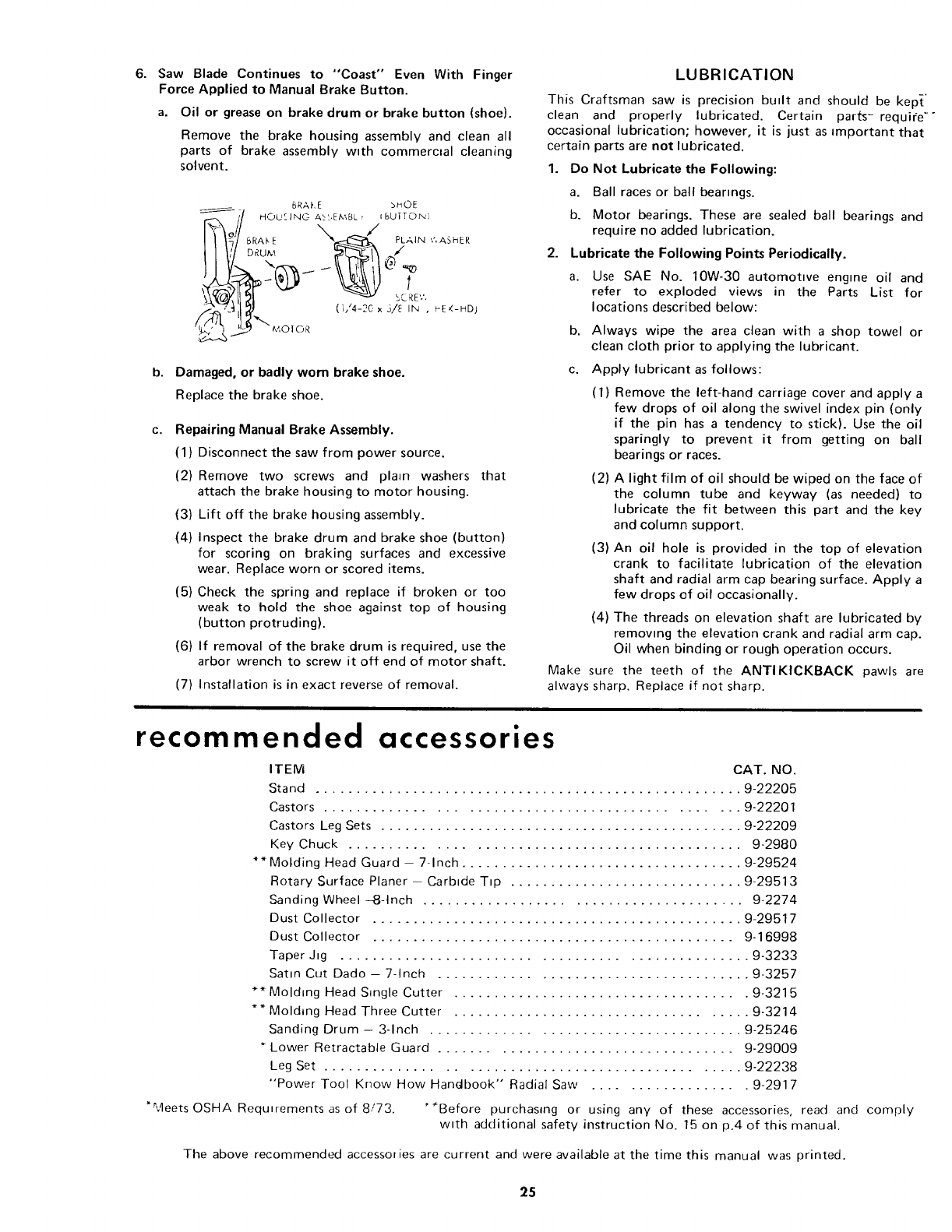
6. SawBladeContinuesto "Coast" Even With Finger
Force Applied to Manual Brake Button.
a. Oil or grease on brake drum or brake button (shoe).
Remove the brake housing assembly and clean all
parts of brake assembly wtth commercial cleaning
solvent.
BRAKE _OE
i_/ H,.OC,:JNOA_'.E_',BL_i_r:,u_To,x_
, D_U_,_ _ /
(_ .s)E_l_' _-_,,,D_
@ _" ,,,,o,o_ -- ....
b. Damaged, or badly worn brake shoe.
Replace the brake shoe.
C. Repairing Manual Brake Assembly.
(1) Disconnect the saw from power source.
(2) Remove two screws and plato washers that
attach the brake housing to motor housing.
(3) Lift off the brake housing assembly.
(4) Inspect the brake drum and brake shoe (button)
for scoring on braking surfaces and excessive
wear. Replace worn or scored items.
(5) Check the spring and replace if broken or too
weak to hold the shoe against top of housing
(button protruding).
(6) If removal of the brake drum is required, use the
arbor wrench to screw it off end of motor shaft.
(7) Installation is in exact reverse of removal.
LUBRICATION
This Craftsman saw is precision built and should be kept'
clean and properly lubricated. Certain parts- require -"
occasional lubrication; however, it is just as amportant that
certain parts are not lubricated.
1. Do Not Lubricate the Following:
a. Ball races or ball bearings.
b. Motor bearings. These are sealed ball bearings and
require no added lubrication.
2. Lubricate the Following Points Periodically.
a. Use SAE No. 10W-30 automottve engme oil and
refer to exploded views in the Parts List for
locations described below:
b. Always wipe the area clean with a shop towel or
clean cloth prior to applying the lubricant.
c. Apply lubricant as follows:
(1) Remove the left-hand carriage cover and apply a
few drops of oil along the swivel index pin (only
if the pin has a tendency to stick). Use the oil
sparingly to prevent it from getting on ball
bearings or races.
(2) A light film of oil should be wiped on the face of
the column tube and keyway (as needed) to
lubricate the fit between this part and the key
and column support.
(3) An oil hole is provided in the top of elevation
crank to facilitate lubrication of the elevation
shaft and radial arm cap bearing surface. Apply a
few drops of oil occasionally.
(4) The threads on elevation shaft are lubricated by
removing the elevation crank and radial arm cap.
Oil when binding or rough operation occurs.
Make sure the teeth of the ANTI KICKBACK pawls are
always sharp. Replace if not sharp.
recommended accessories
*Meets OSHA Requirements as of 8/73.
ITEM CAT. NO.
Stand ..................................................... 9-22205
Castors ................................................ 9-22201
Castors Leg Sets ............................................. 9-22209
Key Chuck ............................................... 9-2980
**Molding Head Guard - 7-Inch ................................... 9-29524
Rotary Surface Planer - Carbide Tip ............................. 9-29513
Sanding Wheel -8-Inch ....................................... 9-2274
Dust Collector .............................................. 9-29517
Dust Collector ............................................. 9-16998
Taper Jig ................................................. 9-3233
Satin Cut Dado - 7-Inch ...................................... 9-3257
** Molding Head Single Cutter .................................... 9-3215
** Molding Head Three Cutter .................................... 9-3214
Sanding Drum - 3-Inch ...................................... 9-25246
Lower Retractable Guard .................................... 9-29009
Leg Set ................................................. 9-22238
"Power Tool Know How Handbook" Radial Saw .................. 9-2917
"*Before purchasing or using any of these accessories, read and comply
with additional safety instruction No. 15 on p.4 of this manual.
The above recommended accessories are current and were available at the time this manual was printed.
25
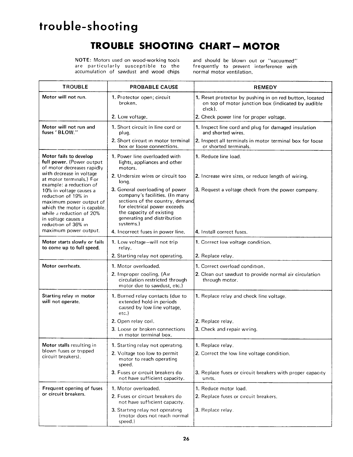
trouble-shooting
TROUBLE SHOOTING
NOTE: Motors used on wood-working tools
are particularly susceptible to the
accumulation of sawdust and wood chips
CHART-- MOTOR
and should be blown out or "vacuumed"
frequently to prevent interference with
normal motor ventilation.
TROUBLE
Motor will not run.
Motor will not run and
fuses ' BLOW."
Motor fails to develop
full power. (Power output
of motor decreases rapidly
with decrease in voltage
at motor terminals.) For
example: a reduction of
10% in voltage causes a
reduction of 19% in
maximum power output of
which the motor is capable.
while areduction of 20%
in voltage causes a
reductton of 36% m
maximum power output.
Motor starts slowly or fails
to come up to full speed.
Motor overheats.
Starting relay in motor
will not operate.
Motor stalls resulting in
blown fuses or tripped
circuit breakers).
Frequent opening of fuses
or circuit breakers.
PROBABLE CAUSE
1. Protector open; circuit
broken.
2.
1.
2.
1.
2.
3.
4,
1.
2.
1.
2.
Low voltage.
Short circuit in line cord or
plug.
Short circutt m motor terminal
box or loose connections.
Power line overloaded with
lights, appliances and other
motors.
Undersize wires or circuit too
long.
General overloading of power
company's facilities. (In many
sections of the country, demand
for electrical power exceeds
the capacity of existing
generating and distribution
systems.)
Incorrect fuses in power line.
Low voltage--will not trip
relay.
Starting relay not operating.
Motor overloaded.
Improper cooling. (Air
circulation restricted through
motor due to sawdust, etc.)
1. Burned relay contacts (due to
extended hold-in periods
caused by low line voltage,
etc.)
2. Open relay cotl.
3. Loose or broken connections
in motor terminal box.
1. Starting relay not operating.
2. Voltage too low to permit
motor to reach operating
speed.
3. Fuses or c_rcuit breakers do
not have sufficient capacity.
1. Motor overloaded.
2. Fuses or circuit breakers do
not have sufficient capactty.
3. Starting relay not operating
(motor does not reach normal
speed.)
REMEDY
1. Reset protector by pushing in on red button, located
on top of motor junction box (indicated by audible
chck).
2. Check power line for proper voltage.
1. Inspect line cord and plug for damaged insulation
and shorted wires.
2. Inspect all terminals in motor terminal box for loose
or shorted terminals.
1. Reduce line load.
2. Increase wire sizes, or reduce length of wiring.
3. Request a voltage check from the power company.
4. Install correct fuses.
1. Correct low voltage condition.
2. Replace relay.
1. Correct overload condition.
2. Clean out sawdust to provide normal air circulation
through motor.
1. Replace relay and check line voltage.
2. Replace relay.
3. Check and repair wtring.
1. Replace relay.
2. Correct the !ow line voltage condition.
3. Replace fuses or circuit breakers with proper capacity
units.
1. Reduce motor load.
2. Replace fuses or c_rcuit breakers.
3. Replace relay.
26
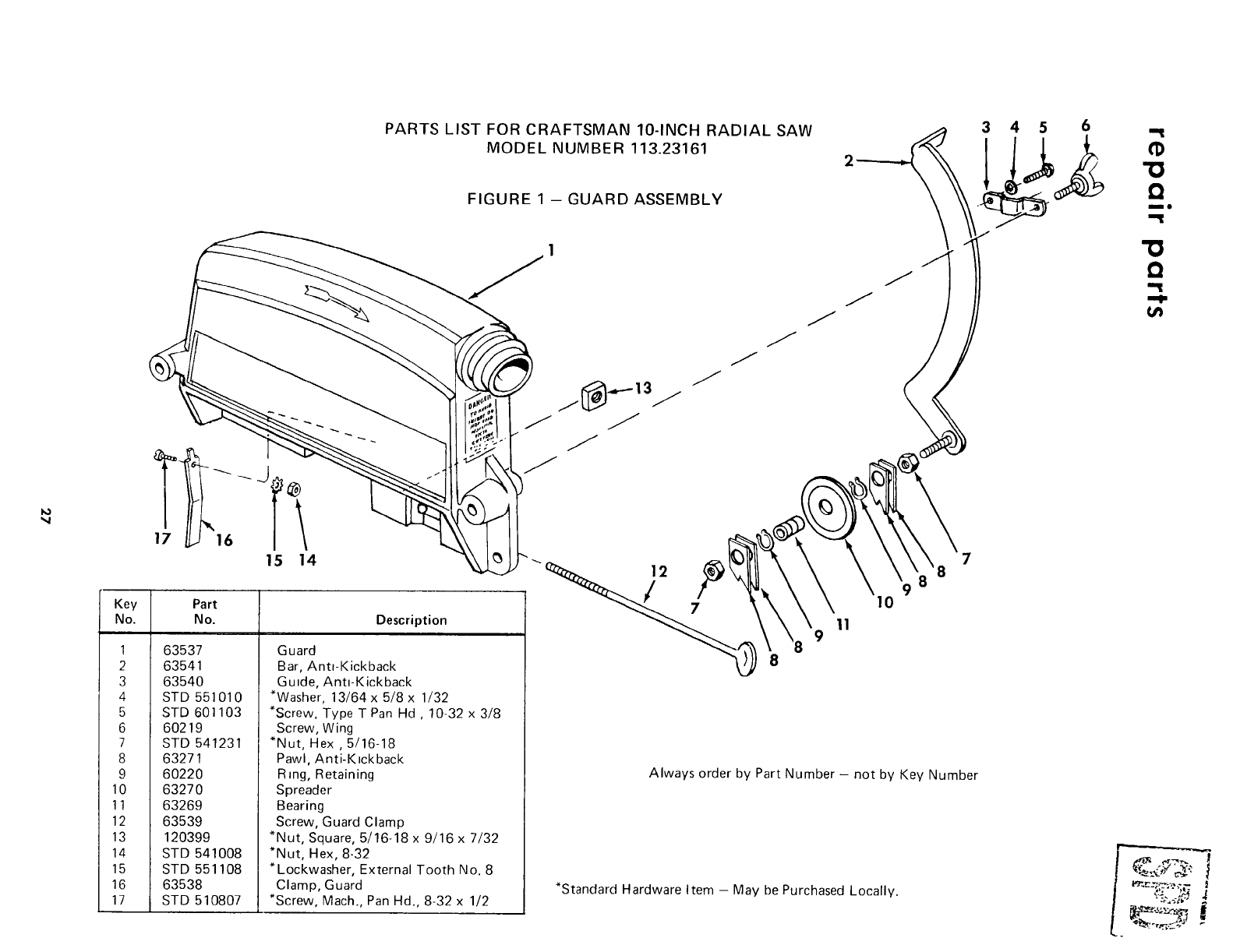
17 j16 1
15 14
Key Part
No. No. Description
PARTS LIST FOR CRAFTSMAN IO-INCH RADIAL SAW
MODEL NUMBER 113.23161
FIGURE 1 - GUARD ASSEMBLY
1 63537
2 63541
3 63540
4 STD 551010
5 STD 601103
6 60219
7 STD 541231
8 63271
9 60220
10 63270
11 63269
12 63539
13 120399
14 STD 541008
15 STD 551108
16 63538
17 STD 510807
Guard
Bar, Anti-Kickback
Gu=de, Ant=-Kickback
*Washer, 13/64 x 5/8 x 1/32
*Screw, Type T Pan Hd , 10-32 x 3/8
Screw, Wing
*Nut, Hex, 5/16-18
Pawl, Anti-Kickback
Ring, Retaining
Spreader
Bearing
Screw, Guard Clamp
*Nut, Square, 5/16-18 x 9/16 x 7/32
*Nut, Hex, 8-32
*Lockwasher, External Tooth No. 8
Clamp, Guard
*Screw, Mach., Pan Hd., 8-32 x 1/2
j[_.,_-13j
J
J
JJJJ
7
8
10
11
Always order by Part Number - not by Key Number
*Standard Hardware Item - May be Purchased Locally.
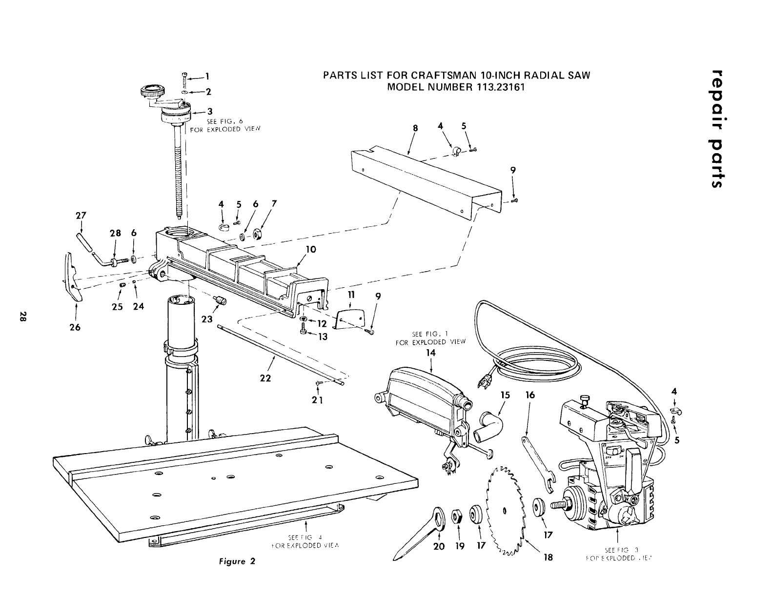
€lo
27
<_ 28 6
l25 24
26
SEE FIG. 6
I FOR EXPLODED ",,;IE,q
Figure 2
PARTS LIST FOR CRAFTSMAN 10-INCH RADIAL SAW
MODEL NUMBER 113.23161
t
SEE FIG 4
FOR EXPLODED ,;lEA
8 4 5
.J /
/
__J
SEE FIG. 1
FOR EXPLODED VIEW
14
18 hOP E_PLODED .IE,'
Q
ml
Q
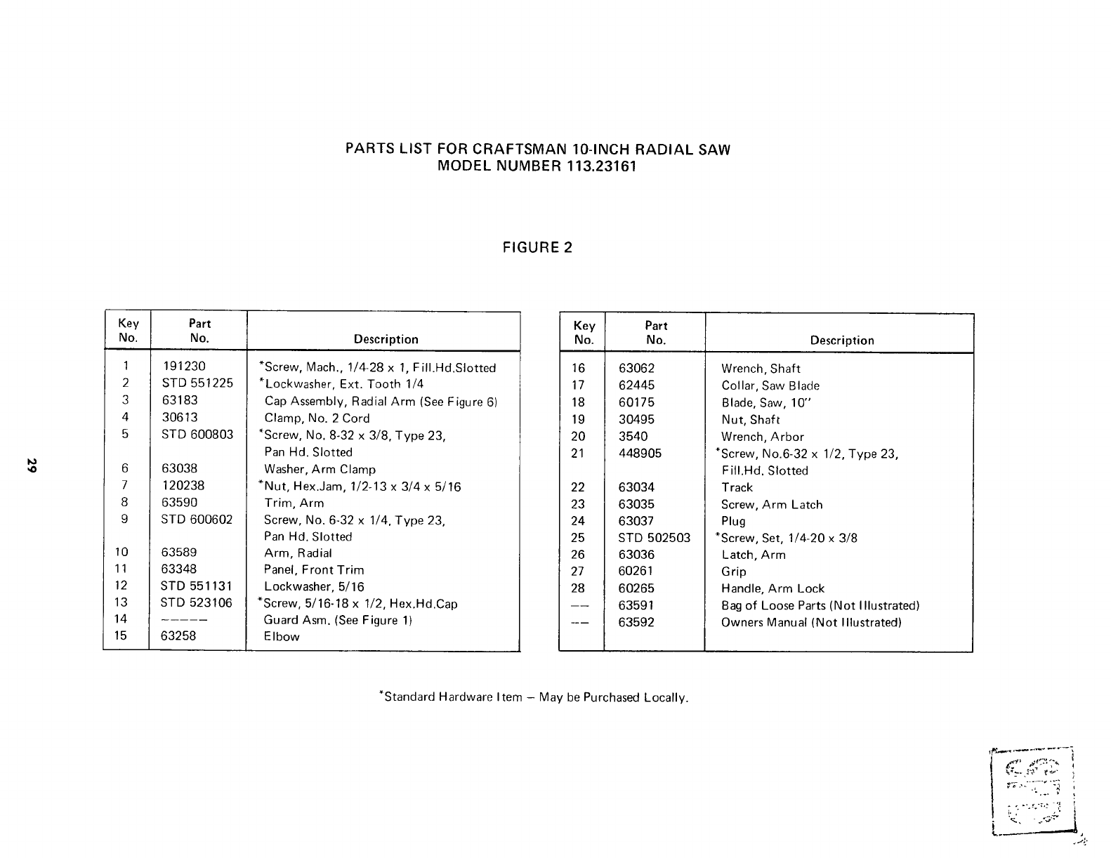
PARTS LIST FOR CRAFTSMAN 10-INCH RADIAL SAW
MODEL NUMBER 113.23161
FIGURE 2
Key Part
No. No. Description
1
2
3
4
5
6
7
8
9
10
11
12
13
14
15
19123O
STD 551225
63183
30613
STD 600803
63038
120238
6359O
STD 600602
63589
63348
STD 551131
STD 523106
63258
*Screw, Mach., 1/4-28 x 1, FilI.Hd.Slotted
*Lockwasher, Ext. Tooth 1/4
Cap Assembly, Radial Arm (See Figure 6)
Clamp, No. 2 Cord
*Screw, No. 8-32 x 3/8, Type 23,
Pan Hd. Slotted
Washer, Arm Clamp
*Nut, Hex.Jam, 1/2-13 x 3/4 x 5/16
Trim, Arm
Screw, No. 6-32 x 1/4, Type 23,
Pan Hd. Slotted
Arm, Radial
Panel, Front Trim
Lockwasher, 5/16
*Screw, 5/16-18 x 1/2, Hex.Hd.Cap
Guard Asm. (See Figure 1)
EIbow
Key Part
No. No. Description
16 63062
17 62445
18 60175
19 30495
20 3540
21 448905
22 63034
23 63035
24 63037
25 STD 502503
26 63036
27 60261
28 60265
63591
63592
Wrench, Shaft
Collar, Saw Blade
Blade, Saw, 10"
Nut, Shaft
Wrench, Arbor
*Screw, No.6-32 x 1/2, Type 23,
F ilI.Hd. Slotted
Track
Screw, Arm Latch
Plug
*Screw, Set, 1/4-20 x 3/8
Latch, Arm
Grip
Handle, Arm Lock
Bag of Loose Parts (Not Illustrated)
Owners Manual (Not Illustrated)
"Standard Hardware Item - May be Purchased Locally.
v _ .,- ._. ".:4
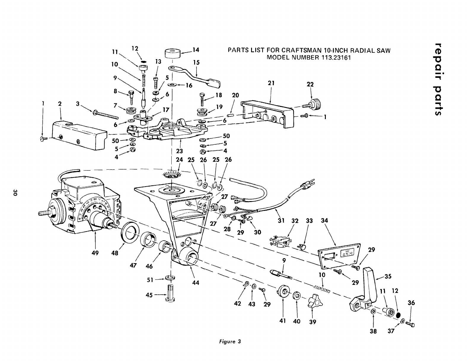
o
Q
me
!3
Q
49 48
47 46
/_31 32 /33 34
29 30 /
/
-'_-_ 29
38
Figure 3
f35
11 12
\1:'
37
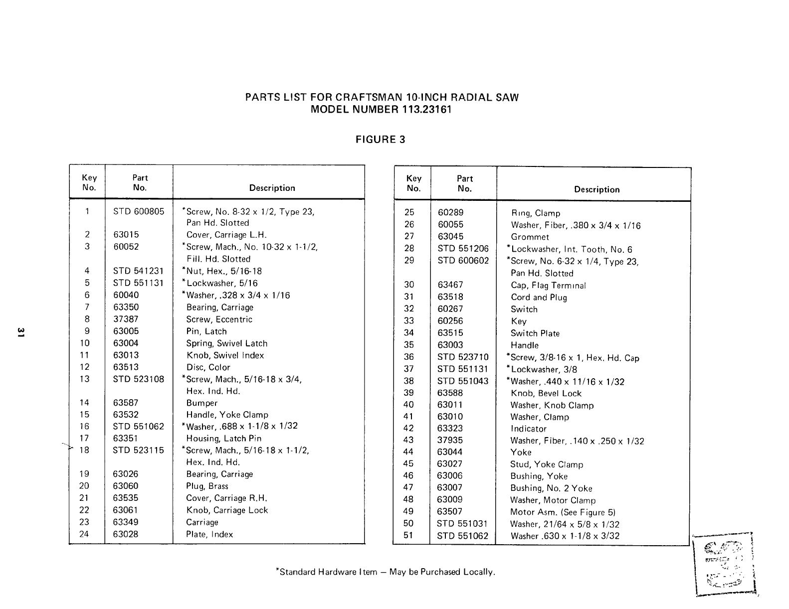
PARTS LIST FOR CRAFTSMAN 10-INCH RADIAL SAW
MODEL NUMBER 113.23161
FIGURE 3
Key Part
No. No. Description
1 STD 600805
2
3
63015
6OO52
4 STD 541231
5 STD 551131
6 60040
7 6335O
8 37387
9 63005
10 63004
11 63013
12 63513
13 STD 523108
14 63587
15 63532
16 STD 551062
17 63351
" 18 STD 523115
19 63026
20 63060
21 63535
22 63061
23 63349
24 63028
*Screw, No. 8-32 x 1/2, Type 23,
Pan Hd. Slotted
Cover, Carriage L.H.
*Screw, Mach., No. 10-32 x 1-!/2,
Fill. Hd. Slotted
*Nut, Hex., 5/16-18
* Lockwasher, 5/16
*Washer, .328 x 3/4 x 1/16
Bearing, Carriage
Screw, Eccentric
Pin, Latch
Spring, Swivel Latch
Knob, Swivel Index
Disc, Color
*Screw, Mach., 5/16-18 x 3/4,
Hex. Ind. Hd.
Bumper
Handle, Yoke Clamp
*Washer, .688 x 1-1/8 x 1/32
Housing, Latch Pin
*Screw, Mach., 5/16-18 x 1-1/2,
Hex. Ind. Hd.
Bearing, Carriage
Plug, Brass
Cover, Carriage R.H.
Knob, Carriage Lock
Carriage
Plate, Index
Key Part
No. No.
25 60289
26 60055
27 63045
28 STD 5512O6
29 STD 600602
30 63467
31 63518
32 6O267
33 60256
34 63515
35 63003
36 STD 523710
37 STD 551131
38 STD 551043
39 63588
40 63011
41 63010
42 63323
43 37935
44 63044
45 63027
46 63006
47 63007
48 63009
49 63507
50 STD 551031
51 STD 551062
Description
R=ng, Clamp
Washer, Fiber, .380 x 3/4 x 1/16
Grommet
*Lockwasher, Int. Tooth, No. 6
*Screw, No. 6-32 x 1/4, Type 23,
Pan Hd. Slotted
Cap, Flag Terminal
Cord and Plug
Switch
Key
Switch Plate
Handle
*Screw, 3/8-16 x 1, Hex. Hd. Cap
* Lockwasher, 3/8
*Washer, .440x 11/16 x 1/32
Knob, Bevel Lock
Washer, Knob Clamp
Washer, Clamp
Indicator
Washer, Fiber, .140 x .250 x 1/32
Yoke
Stud, Yoke Clamp
Bushing, Yoke
Bushing, No. 2 Yoke
Washer, Motor Clamp
Motor Asm. (See Figure 5)
Washer, 21/64 x 5/8 x 1/32
Washer .630 x 1-1/8 x 3/32
*Standard Hardware Item - May be Purchased Locally.
I
_¢_ ,-*:."t,.
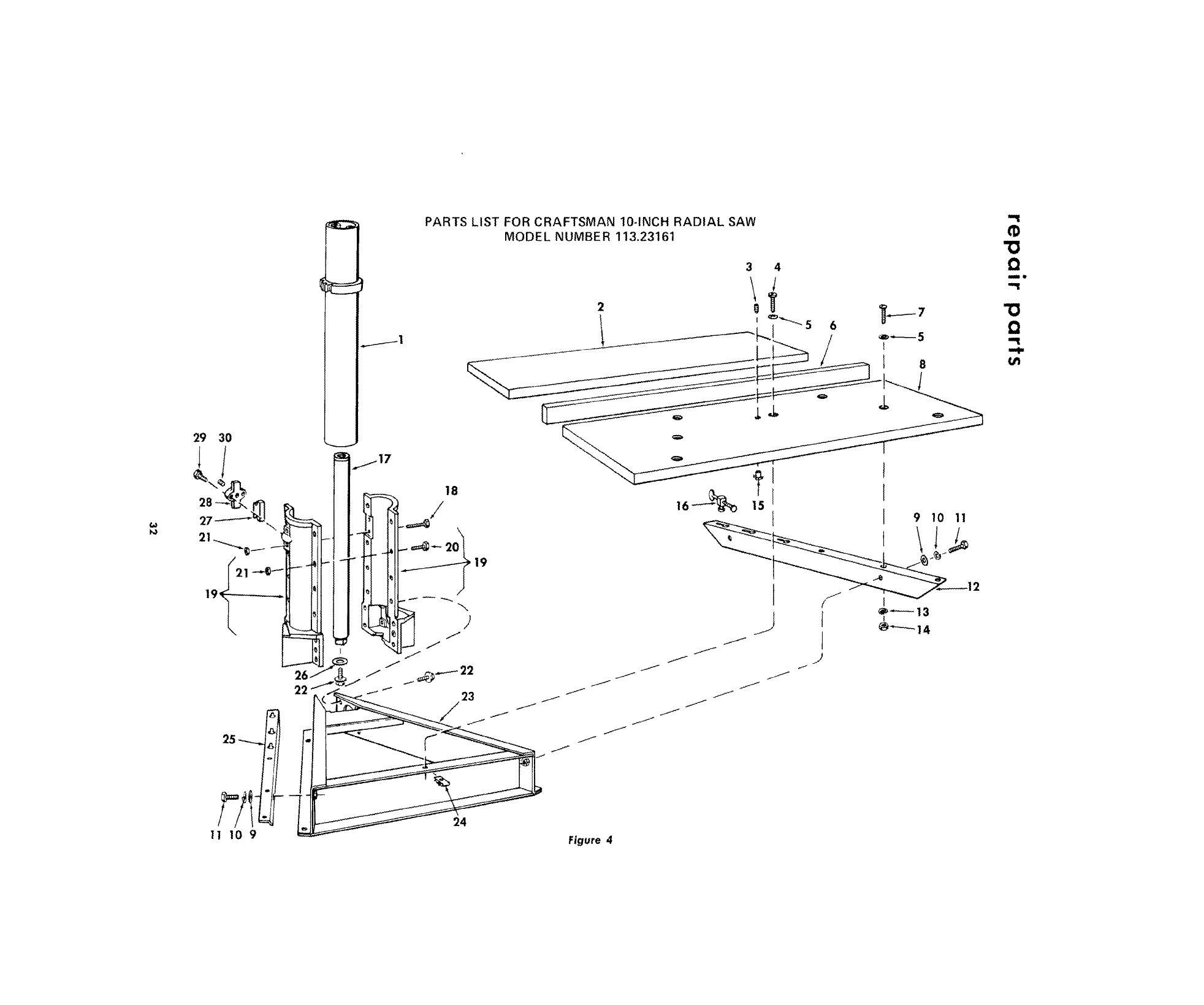
22
25
11 10 9
jl
PARTS LIST FOR CRAFTSMAN 10-INCH RADIAL SAW
MODEL NUMBER 113,23161
18
/
19
J
24
Figure 4
"13
Q
lit
"13
Q
U'J
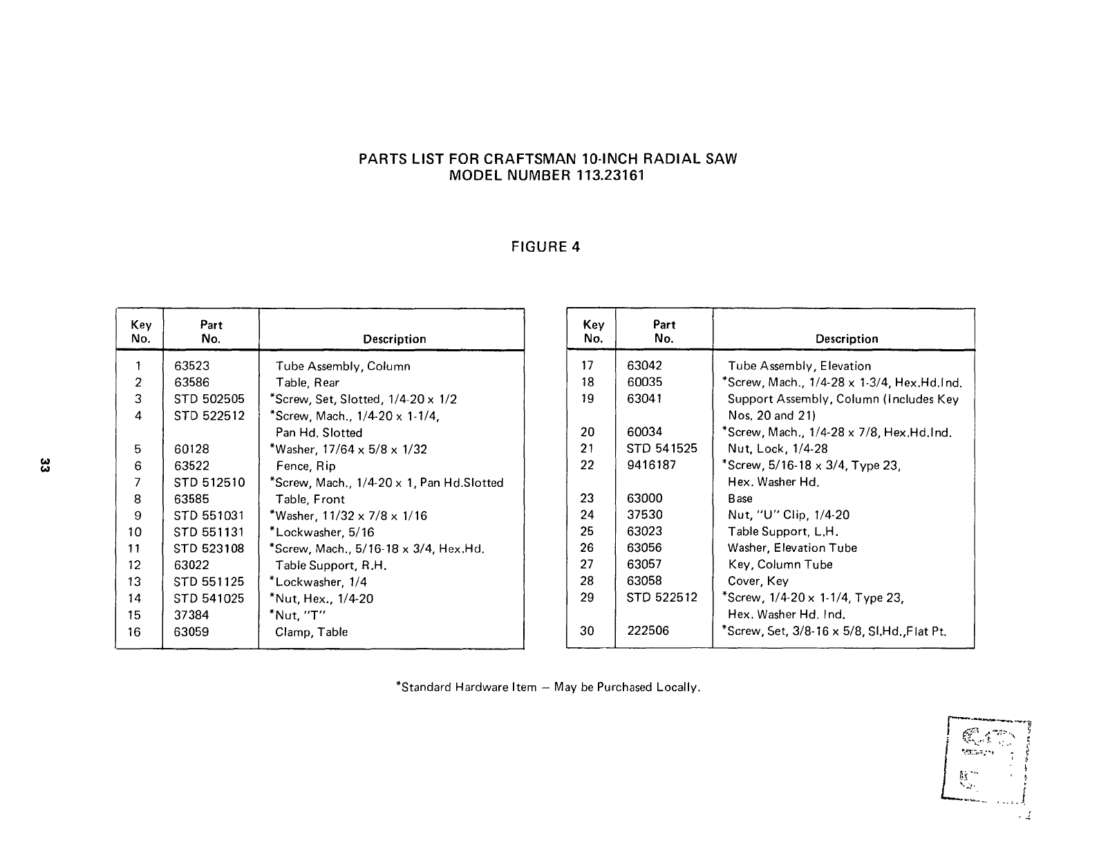
PARTS LIST FOR CRAFTSMAN 10-INCH RADIAL SAW
MODEL NUMBER 113.23161
FIGURE 4
Key Part
No. No. Description
1
2
3
4
5
6
7
8
9
10
11
12
13
14
15
16
63523
63586
STD 5O2505
STD 522512
60128
63522
STD 512510
63585
STD 551031
STD 551131
STD 523108
63022
STD 551125
STD 541025
37384
63059
Tube Assembly, Column
Table, Rear
*Screw, Set, Slotted, 1/4-20 x 1/2
*Screw, Mach., 1/4-20 x 1-1/4,
Pan Hd. Slotted
*Washer, 17/64 x 5/8 x 1/32
Fence, Rip
*Screw, Mach., 1/4-20 x 1, Pan Hd.Slotted
Table, Front
*Washer, 11/32 x 7/8 x 1/16
* Lockwasher, 5/16
*Screw, Mach., 5/16-18 x 3/4, Hex.Hd.
Table Support, R.H.
* Lockwasher, 1/4
*Nut, Hex., 1/4-20
*Nut, "T"
Clamp, Table
Key Part
No. No. Description
17 63042
18 6O035
19 63041
20
21
22
23
24
25
26
27
28
29
3O
60034
STD 541525
9416187
Tube Assembly, Elevation
*Screw, Mach., 1/4-28 x 1-3/4, Hex.Hd.lnd.
Support Assembly, Column (Includes Key
Nos. 20 and 21)
*Screw, Mach., 1/4-28 x 7/8, Hex.Hd.lnd.
Nut, Lock, 1/4-28
*Screw, 5/16-18 x 3/4, Type 23,
Hex. Washer Hd.
63000
37530
63023
63056
63057
63058
STD 522512
222506
Base
Nut, "U" Clip, 1/4-20
Table Support, L.H.
Washer, Elevation Tube
Key, Column Tube
Cover, Key
*Screw, 1/4-20 x 1-1/4, Type 23,
Hex. Washer Hal. Ind.
*Screw, Set, 3/8-16 x 5/8, SI.Hd.,Flat Pt.
*Standard Hardware Item - May be Purchased Locally.
.......i
,j
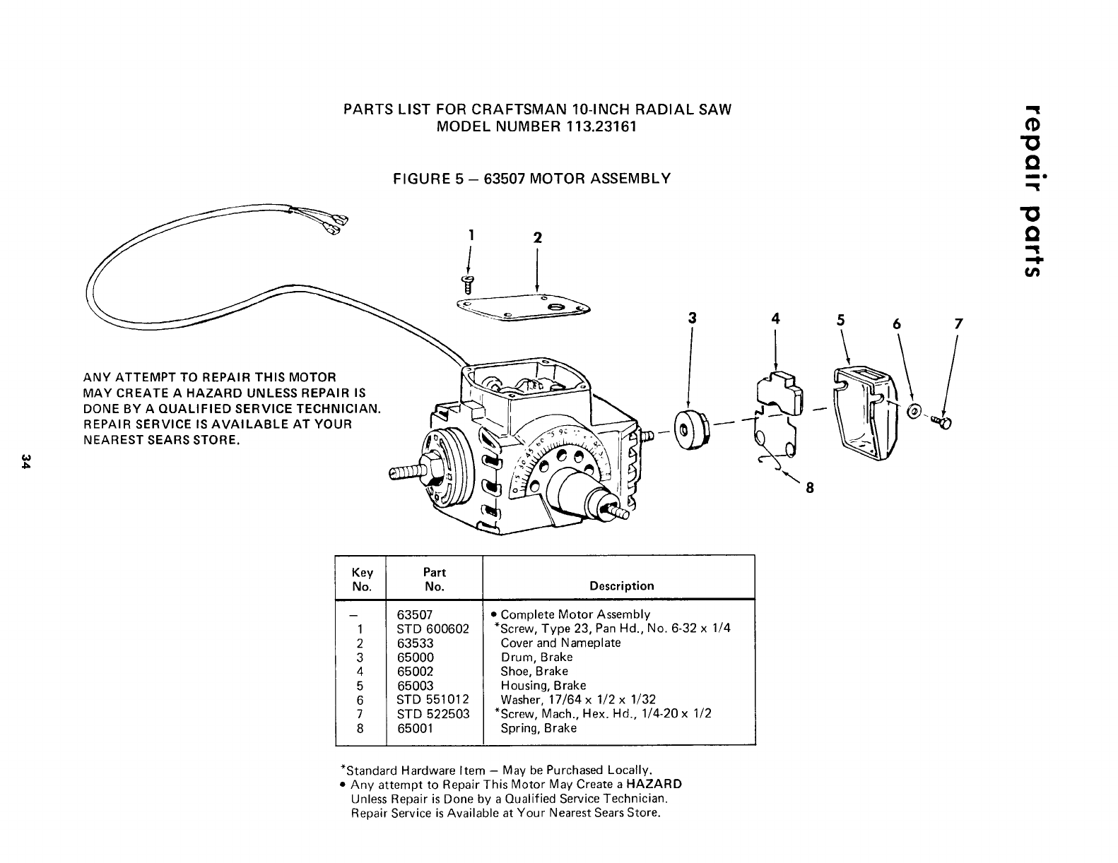
w
ANY ATTEMPT TO REPAIR THIS MOTOR
MAY CREATE A HAZARD UNLESS REPAIR IS
DONE BY A QUALIFIED SERVICE TECHNICIAN.
REPAIR SERVICE IS AVAILABLE AT YOUR
NEAREST SEARS STORE.
PARTS LIST FOR CRAFTSMAN 10-INCH RADIAL SAW -I
MODEL NUMBER 113.23161 "O
FIGURE 5 - 63507 MOTOR ASSEMBLY _"
Key Part
No. No. Description
- 63507
1 STD 600602
2 63533
3 65000
4 65002
5 65003
6 STD 551012
7 STD 522503
8 65001
•Complete Motor Assembly
*Screw, Type 23, Pan Hd., No. 6-32 x 1/4
Cover and Nameplate
Drum, Brake
Shoe, Brake
Housing, Brake
Washer, 17/64 x 1/2 x 1/32
*Screw, Mach., Hex. Hd., 1/4-20 x 1/2
Spring, Brake
*Standard Hardware Item -May be Purchased Locally.
• Any attempt to Repair This Motor May Create a HAZARD
Unless Repair is Done by a Qualified Service Technician.
Repair Service is Available at Your Nearest Sears Store.
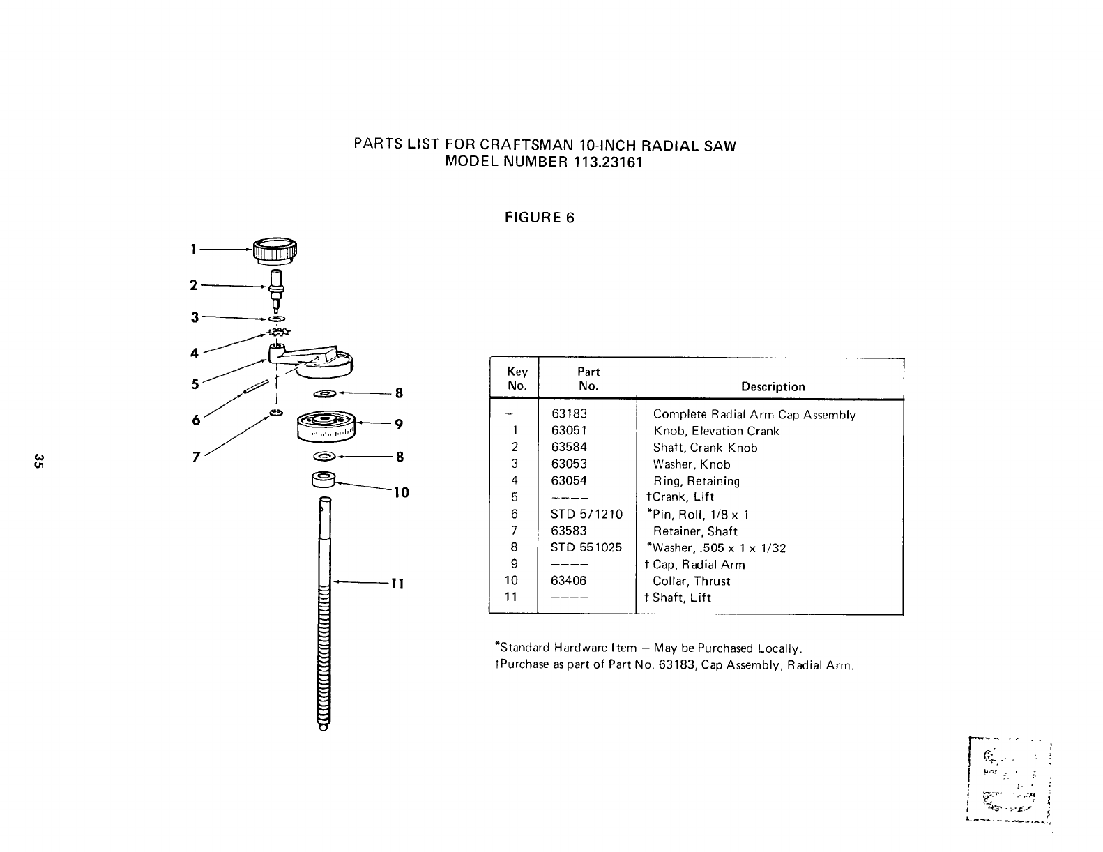
PARTS LIST FOR CRAFTSMAN 10-INCH RADIAL SAW
MODEL NUMBER 113.23161
!
2
58
8
FIGURE 6
Key Part
No. No. Description
- 63183
1 63051
2 63584
3 63053
4 63054
5
6 STD 571210
7 63583
8 STD 551025
9
10 63406
11
Complete Radial Arm Cap Assembly
Knob, Elevation Crank
Shaft, Crank Knob
Washer, Knob
Ring, Retaining
tCrank, Lift
*Pin, Roll, 1/8 x 1
Retainer, Shaft
*Washer, .505 x 1 x 1/32
t Cap, Radial Arm
Collar, Thrust
t Shaft, Lift
*Standard Hardware Item - May be Purchased Locally.
tPurchase as part of Part No. 63183, Cap Assembly, Radial Arm.
t. •
E;_- "", I
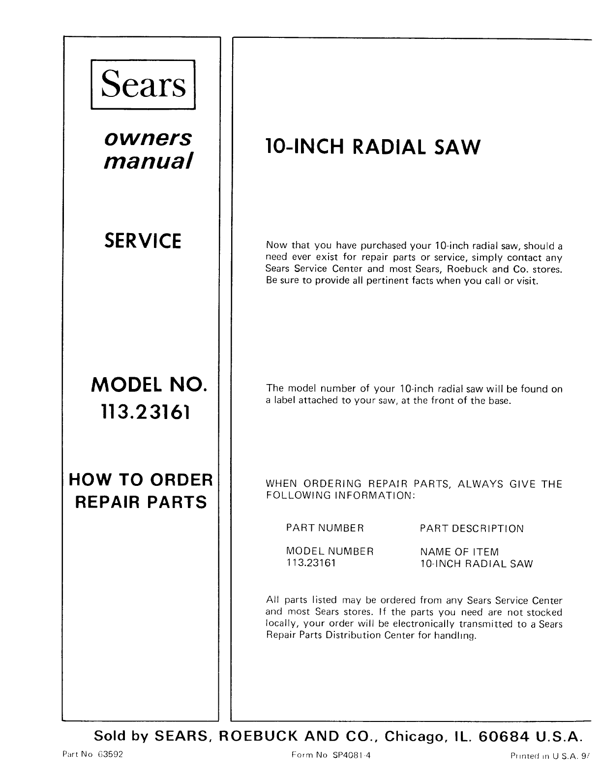
Sears
owners
manual
SERVICE
MODEL NO.
113.23161
HOW TO ORDER
REPAIR PARTS
IO-INCH RADIAL SAW
Now that you have purchased your 10-inch radial saw, should a
need ever exist for repair parts or service, simply contact any
Sears Service Center and most Sears, Roebuck and Co. stores.
Be sure to provide all pertinent facts when you call or visit.
The model number of your 10-inch radial saw will be found on
a label attached to your saw, at the front of the base.
WHEN ORDERING REPAIR PARTS, ALWAYS GIVE THE
FOLLOWING INFORMATION:
PART NUMBER
MODEL NUMBER
113.23161
PART DESCRIPTION
NAME OF ITEM
10-INCH RADIAL SAW
All parts listed may be ordered from any Sears Service Center
and most Sears stores. If the parts you need are not stocked
locally, your order will be electronically transmitted to a Sears
Repair Parts Distribution Center for handltng.
Sold by SEARS, ROEBUCK AND CO., Chicago, IL. 60684 U.S.A.
Part No 63592 Form No SP4081 4 Printed _n U S.A. 9/
