Craftsman 113234700 User Manual RADIAL ARM SAW Manuals And Guides L0803157
CRAFTSMAN Saw Radial Manual L0803157 CRAFTSMAN Saw Radial Owner's Manual, CRAFTSMAN Saw Radial installation guides
User Manual: Craftsman 113234700 113234700 CRAFTSMAN RADIAL ARM SAW - Manuals and Guides View the owners manual for your CRAFTSMAN RADIAL ARM SAW #113234700. Home:Tool Parts:Craftsman Parts:Craftsman RADIAL ARM SAW Manual
Open the PDF directly: View PDF ![]() .
.
Page Count: 88
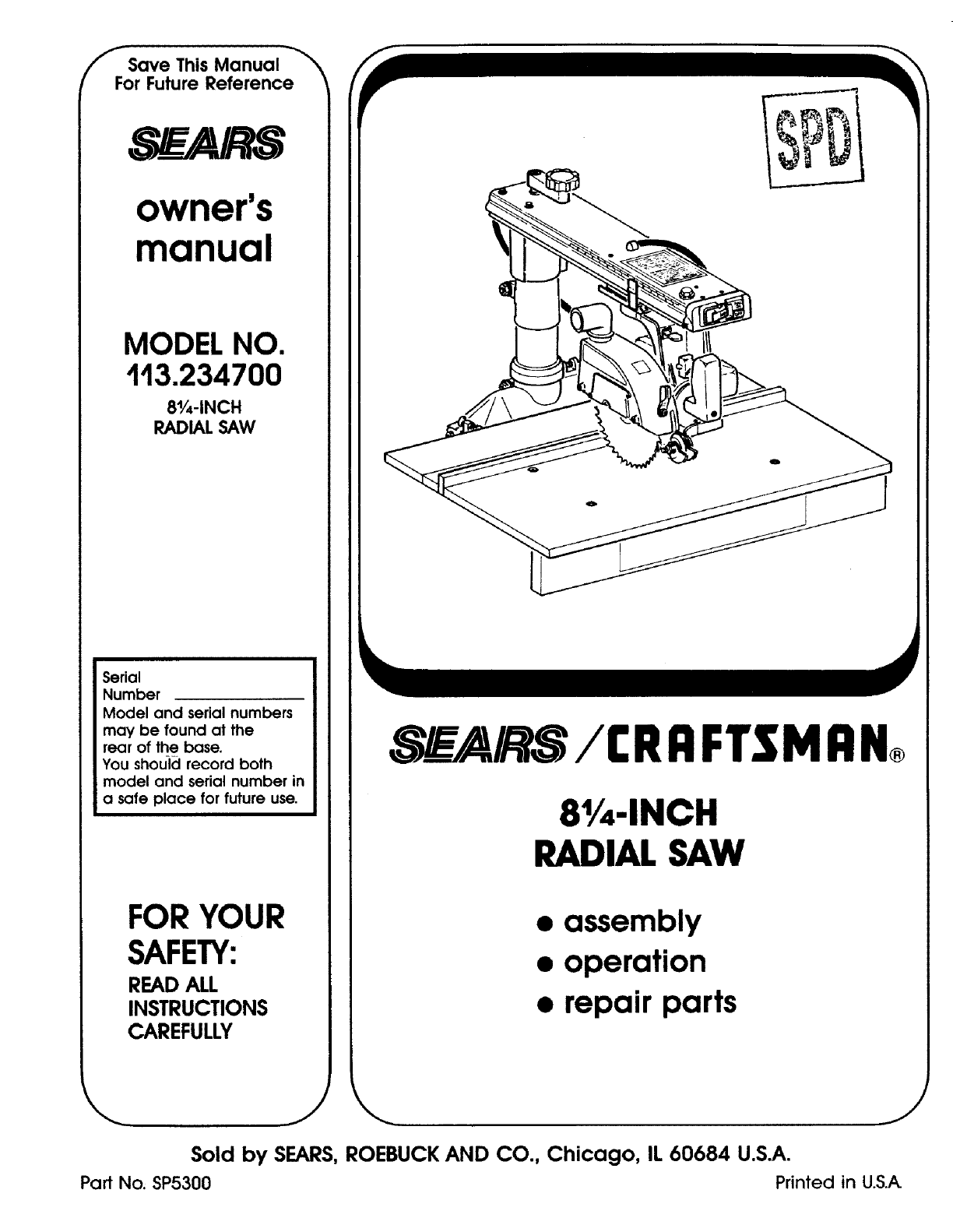
fSave This Manual
For Future Reference
owner's
manual
MODEL NO.
113.234700
81/4-1NCH
RADIAL SAW
Serial
Number
Model and serial numbers
may be found at the
rear of the base.
You shouicl record both
model and serial number in
a safe place for future use.
FOR YOUR
SAFETY:
READ ALL
INSTRUCTIONS
CAREFULLY
SEARS / CRRFTSMRN®
81/4-INCH
RADIAL SAW
• assembly
•operation
•repair parts
\ i/
Sold by SEARS, ROEBUCK AND CO., Chicago, IL 60684 U.S.A.
Part No. SP5300 Printed in U.S.A
Table of Contents
Section Title .......................... Page
Safety ......................................... 3
Assembly ...................................... 12
Controls ....................................... 24
Alignment and Adjustment ............................ 28
Electrical Connections ............................... 39
Crosscutting ..................................... 40
Ripping ....................................... 50
Cutting Aides .................................... 63
Accessories ..................................... 67
Maintenance .................................... 69
Troubleshooting .................................. 73
Repair Parts ..................................... 78
Index ......................................... 87
FULL ONE YEAR WARRANTY ON CRAFTSMAN RADIAL ARM SAW
If within one year from the date of purchase, this Craftsman Radial Saw fails due
to a defect in material or workmanship, Sears will repair it, free of charge.
WARRANTY SERVICE IS AVAILABLE BY SIMPLY CONTACTING THE
NEAREST SEARS SERVICE CENTER/DEPARTMENT THROUGHOUT THE
UNITED STATES.
This warranty applies only while this product is used in the United States.
This warranty gives you specific legal rights and you may also have other rights
which vary from state to state.
SEARS, ROEBUCK AND CO. DEPT. 698/731A SEARS TOWER,
CHICAGO, IL 60684
Safety
This manual has safety information and
instructions to help users eliminate or
reduce the risk of accidents and injuries,
including:
1. Severe cuts, and loss of fingers or
other body parts due to contact with the
blade
2. Eye impact injuries, and blindness,
from being hit by a thrown workpiece,
workpiece chips or pieces of blade
3. Bodily impact injuries, broken bones,
and internal organ damage from being
hit by a thrown workpiece
4. Shock or electrocution
5. Burns.
Safety Symbol and Signal
Words
An exclamation mark inside a triangle is
the safety alert symbol.
It is used to draw attention to safety in-
formation in the manual and on the saw.
It is$ollowed by a signal word,
DANGER, WARNING, or CAUTION,
which tells the level of risk:
DANGER: means if the safety infor-
mation is not followed someone will be
seriously injured or killed.
_ WARNING: means if the safety in-
formation is not followed someone
could be seriously injured or killed.
CAUTION: means if the safety in-
formation is not followed someone may
be injured.
Read and follow the safety information
and instructions.
Major Hazards
Three major hazards are associated with
using the radial arm saw for ripping.
They are outfeed zone hazard, kickback,
and wrong way feed. This section only
briefly explains these hazards. Read the
ripping and crosscutting safety sections
for more detailed explanations of these
and other hazards.
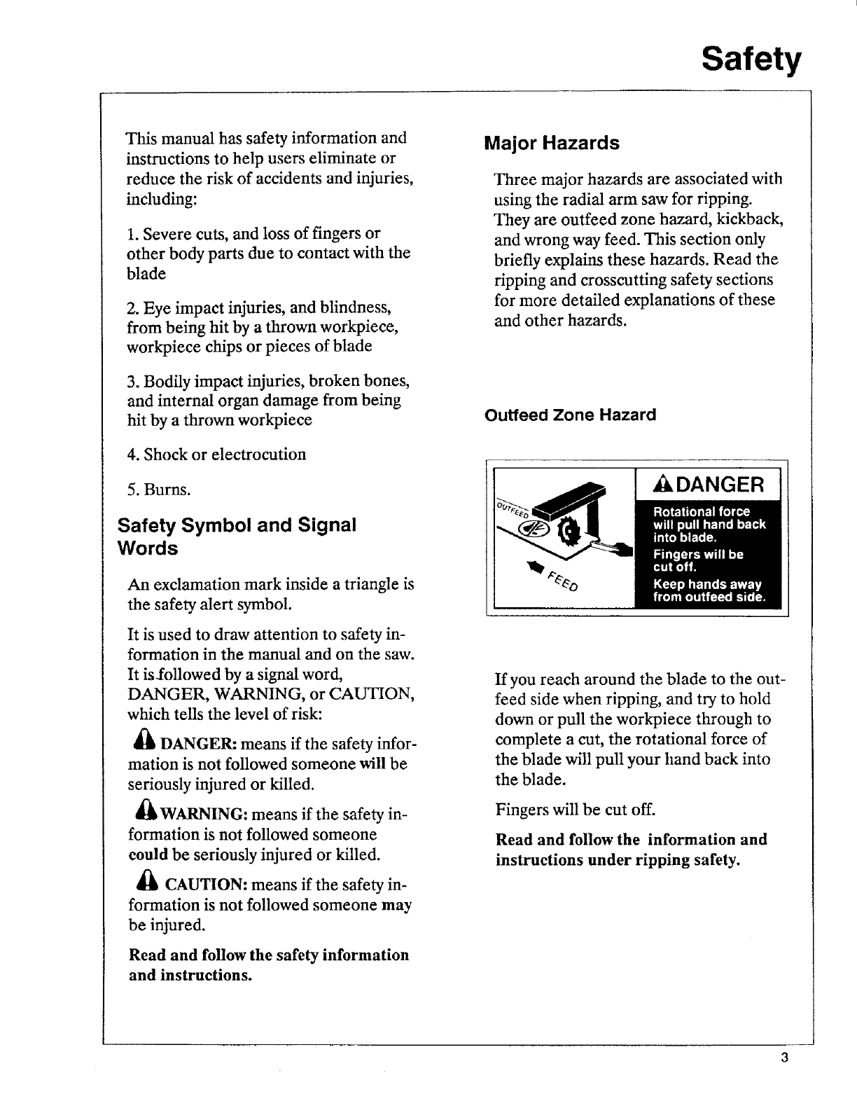
Outfeed Zone Hazard
,_DANGER
If you reach around the blade to the out-
feed side when ripping, and try to hold
down or pull the workpiece through to
complete a cut, the rotational force of
the blade will pull your hand back into
the blade.
Fingers will be cut off.
Read and follow the information and
instructions under ripping safety.
Safety
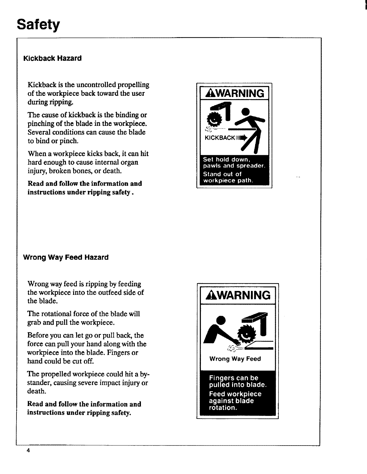
Kickback Hazard
Kickback is the uncontrolled propelling
of the workpiece back toward the user
during ripping.
The cause of kickback is the binding or
pinching of the blade in the workpiece.
Several conditions can cause the blade
to bind or pinch.
When a workpiece kicks back, it can hit
hard enough to cause internal organ
injury, broken bones, or death.
Read and follow the information and
instructions under Hpping safety.
kWARNING
KICKBACKI!I_
Wrong Way Feed Hazard
Wrong way feed is ripping by feeding
the workpiece into the outfeed side of
the blade.
The rotational force of the blade will
grab and pull the workpiece.
Before you can let go or pull back, the
force can pull your hand along with the
workpiece into the blade. Fingers or
hand could be cut off.
The propelled workpiece could hit a by-
stander, causing severe impact injury or
death.
Read and follow the information and
instructions under ripping safety.
kWARNING
Wrong Way Feed
Safety
Safety Instructions
Read and follow these safety instruc-
tions.
Personal Safety Instructions
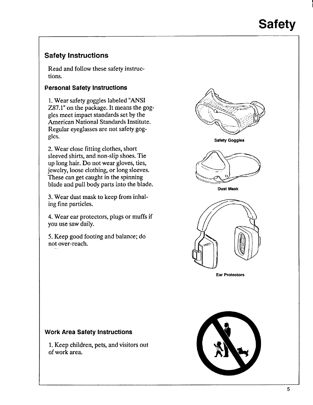
1. Wear safety goggles labeled "ANSI
Z87.1" on the package. It means the gog-
gles meet impact standards set by the
American National Standards Institute.
Regular eyeglasses are not safety gog-
gles.
2. Wear closefitting clothes, short
sleeved shirts, and non-slip shoes. Tie
up long hair. Do not wear gloves, ties,
jewelry, loose clothing, or long sleeves.
These can get caught in the spinning
blade and pull body parts into the blade.
3. Wear dust mask to keep from inhal-
ing fine particles.
4. Wear ear protectors, plugs or muffs if
you use saw daily.
5. Keep good footing and balance; do
not over-reach.
Safety Goggles
Dust Mask
Ear Protectors
Work Area Safety Instructions
1. Keep children, pets, and visitors out
of work area.
Safety
2. Turn saw off, remove yellow key, and
unplug before leaving work area. Do
not leave saw until blade has stopped
spinning.
3. Make work area child-proof: remove
yellow key to prevent accidental start-
up; store key out of sight and reach;
lock work area.
4. Keep floors clean and free of saw-
dust, wax and other slippery materials.
5. Keep work area well lighted and un-
cluttered.
6. Use saw only in dry area. Do not use
in wet or damp areas.
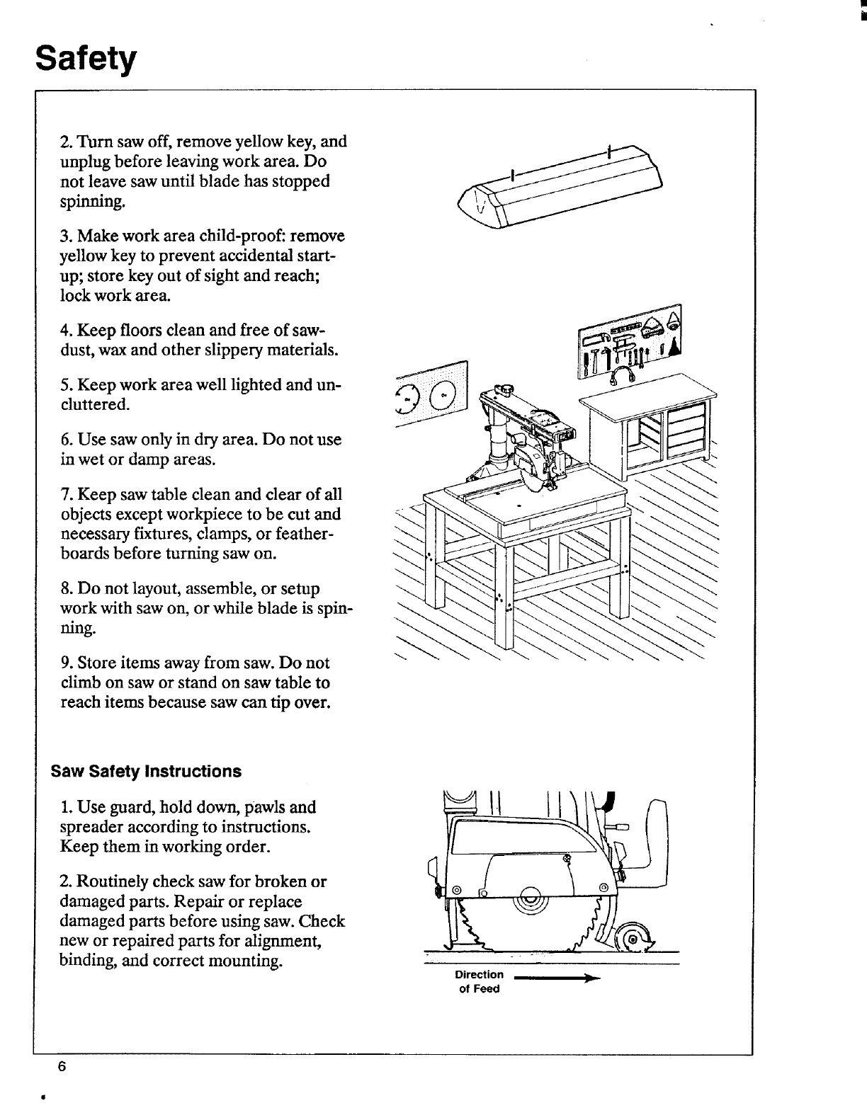
7. Keep saw table clean and clear of all
objects except workpiece to be cut and
necessary fixtures, damps, or feather-
boards before turning saw on.
8. Do not layout, assemble, or setup
work with saw on, or while blade is spin-
ning.
9. Store items away from saw. Do not
climb on saw or stand on saw table to
reach items because saw can tip over.
Saw Safety Instructions
1. Use guard, hold down, pawls and
spreader according to instructions.
Keep them in working order.
2. Routinely check saw for broken or
damaged parts. Repair or replace
damaged parts before using saw. Check
new or repaired parts for alignment,
binding, and correct mounting.
Direction
of Feed
6
Safety
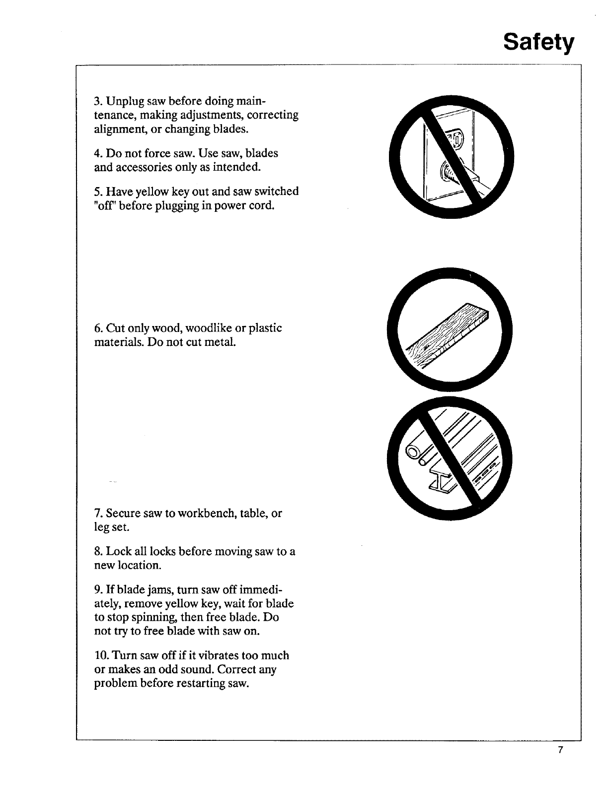
3. Unplug saw before doing main-
tenance, making adjustments, correcting
alignment, or changing blades.
4. Do not force saw. Use saw, blades
and accessories only as intended.
5. Have yellow key out and saw switched
"off' before plugging in power cord.
6. Cut only wood, woodlike or plastic
materials. Do not cut metal.
7. Secure saw to workbench, table, or
leg set.
8. Lock all locks before moving saw to a
new location.
9. If blade jams, turn saw off immedi-
ately, remove yellow key, wait for blade
to stop spinning, then free blade. Do
not try to free blade with saw on.
10. Turn saw off if it vibrates too much
or makes an odd sound. Correct any
problem before restarting saw.
Safety
Workpiece Safety Instructions
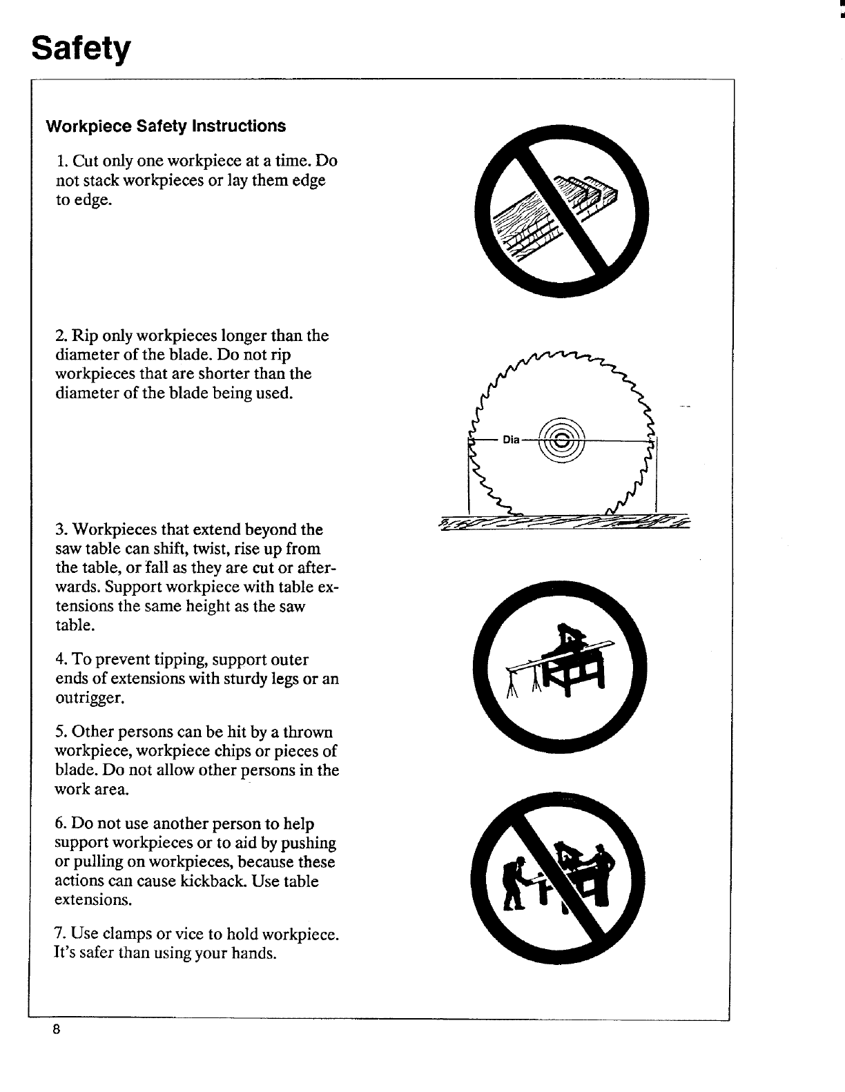
1. Cut only one workpiece at a time. Do
not stack workpieces or lay them edge
to edge.
2. Rip only workpieces longer than the
diameter of the blade. Do not rip
workpieces that are shorter than the
diameter of the blade being used.
3. Workpieces that extend beyond the
saw table can shift, twist, rise up from
the table, or fall as they are cut or after-
wards. Support workpiece with table ex-
tensions the same height as the saw
table.
4. To prevent tipping, support outer
ends of extensions with sturdy legs or an
outrigger.
5. Other persons can be hit by a thrown
workpiece, workpiece chips or pieces of
blade. Do not allow other persons in the
work area.
6. Do not use another person to help
support workpieces or to aid by pushing
or pulling on workpieces, because these
actions can cause kickback. Use table
extensions.
7. Use clamps or vice to hold workpiece.
It's safer than using your hands.
I
8
Safety
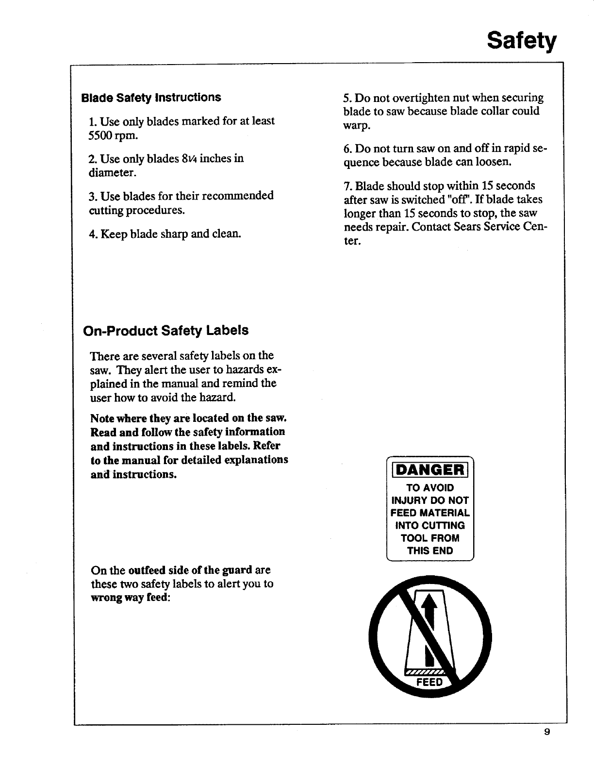
Blade Safety Instructions
1. Use only blades marked for at least
5500rpm.
2. Use only blades 8v4 inches in
diameter.
3. Use blades for their recommended
cutting procedures.
4. Keep blade sharp and clean.
5. Do not overtighten nut when securing
blade to saw because blade collar could
warp.
6. Do not turn saw on and off in rapid se-
quence because blade can loosen.
7. Blade should stop within 15 seconds
after saw is switched "off'. If blade takes
longer than 15 seconds to stop, the saw
needs repair. Contact Sears Service Cen-
ter.
On-Product Safety Labels
There are several safety labels on the
saw. They alert the user to hazards ex-
plained in the manual and remind the
user how to avoid the hazard.
Note where they are located on the saw.
Read and follow the safety information
and instructions in these labels. Refer
to the manual for detailed explanations
and instructions.
On the outfeed side of the guard are
these two safety labels to alert you to
wrong way feed:
DANGER
TO AVOID
INJURY DO NOT
FEED MATERIAL
INTO CUTTING
TOOL FROM
THIS END
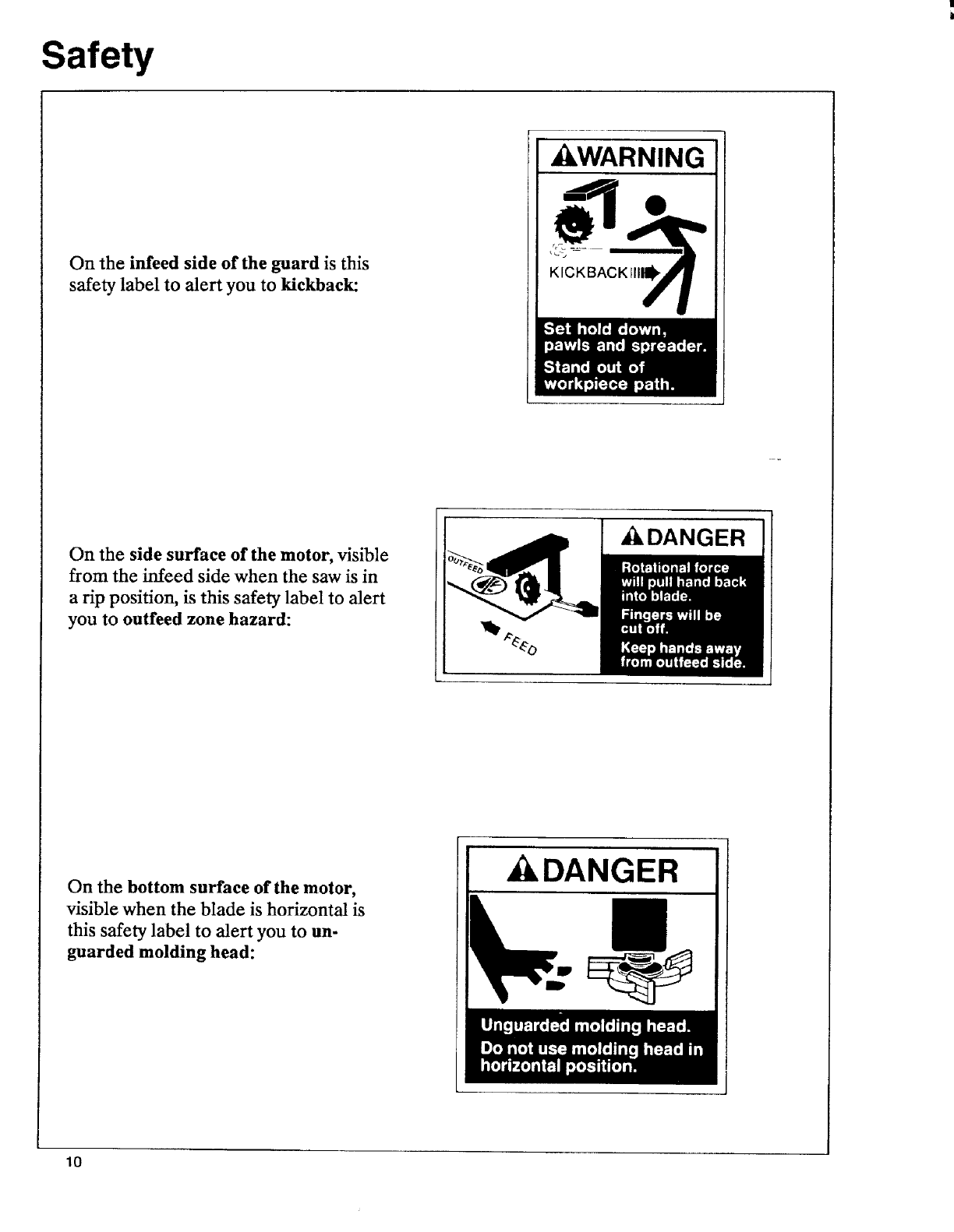
Safety
On the infeed side of the guard is this
safety label to alert you to kickback:
_I_WARNING
KICKBACKIII_
On the side surface of the motor, visible
from the infeed side when the saw is in
a rip position, is this safety label to alert
you to outfeed zone hazard:
_IkDANGER
On the bottom surface of the motor,
visible when the blade is horizontal is
this safety label to alert you to un-
guarded molding head:
DANGER
10
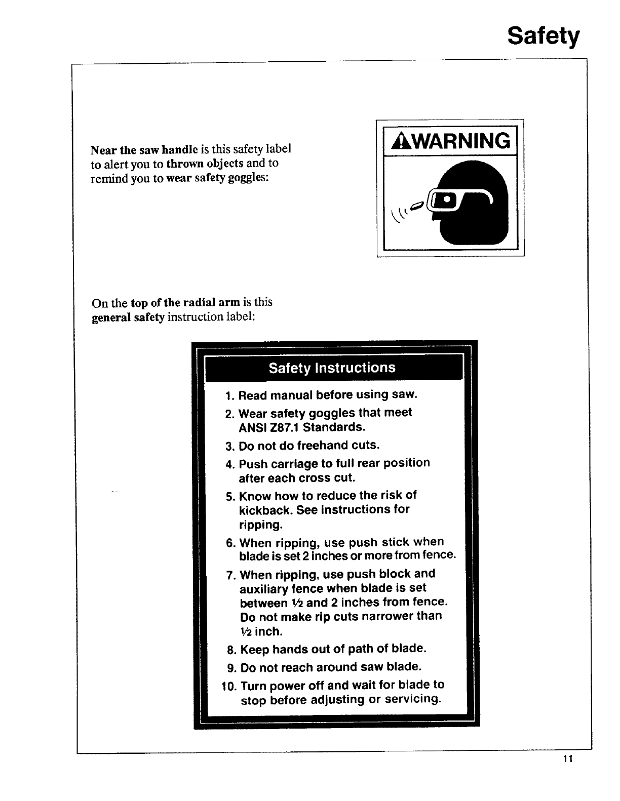
Safety
Near the saw handle is this safety label
to alert you to thrown objects and to
remind you to wear safety goggles:
ILWARNING
On the top of the radial arm is this
general safety instruction label:
1. Read manual before using saw.
2. Wear safety goggles that meet
ANSI Z87.1 Standards.
3. Do not do freehand cuts.
4. Push carriage to full rear position
after each cross cut.
5. Know how to reduce the risk of
kickback. See instructions for
ripping.
6. When ripping, use push stick when
blade is set 2 inches or more from fence.
7. When ripping, use push block and
auxiliary fence when blade is set
between 1/2and 2 inches from fence.
Do not make rip cuts narrower than
1/2inch.
8. Keep hands out of path of blade.
9. Do not reach around saw blade.
10. Turn power off and wait for blade to
stop before adjusting or servicing.
11

Assembly
It is important for your safety and to get
accurate cuts that you put the saw
together according to these instructions.
Identifying Parts
The following parts are included:
Note: Before beginning assembly, check
that all parts are included. If you are miss-
ing any part do not assemble saw. Con-
tact your Sears Service Center or Retail
Store and get the missing part. Sometimes
small parts can get lost in packaging
material Do not throw away any packag-
ing until saw is put together. Check pack-
aging for missing parts before contacting
Sears. A complete parts list (Repair
Parts) is at the end of the manual. Use
the list to identify the number of the miss-
ing part.
A. Radial Arm ................................. 1
B. Blade Carriage ............................ 1
C. Base .............................................. 1
D. Side Frame .................................. 2
E. Table Support ............................. 2
F. Front Stiffener ............................. 1
G. Rear Table .................................. 1
H. Spacer Table ................. .............. 1
I. Rip Fence ...................................... 1
J. Front Table ................................... 1
K_Dust Elbow .................................. 1
12
Assembly
A
C
E
B
D
M
F N
H "e4_
©
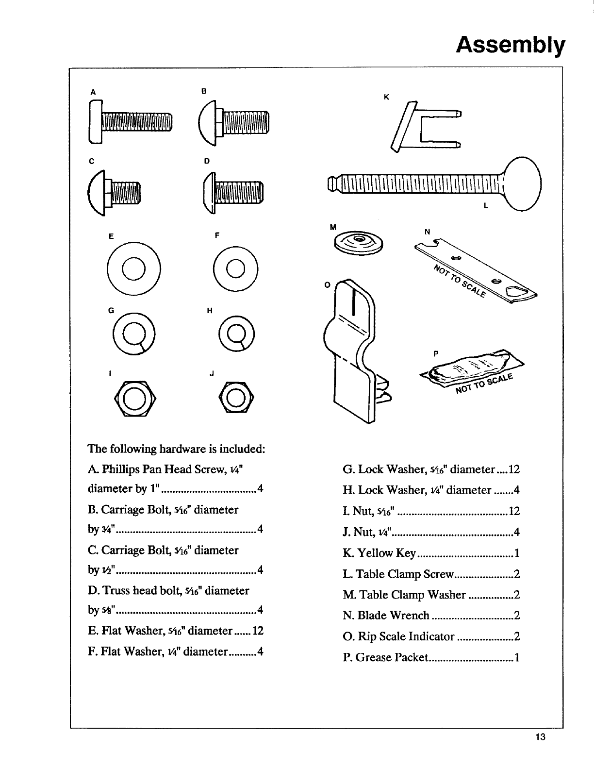
The following hardware is included:
A. Phillips Pan Head Screw, 1/4"
diameter by 1" .................................. 4
B. Carriage Bolt, _6" diameter
by 3/4".................................................. 4
C. Carriage Bolt, _/16"diameter
by ld".................................................. 4
D. Truss head bolt, Y16"diameter
bye" .................................................. 4
E. Flat Washer, Yt6"diameter ...... 12
F. Flat Washer, v4"diameter ..........4
G. Lock Washer, Y16"diameter.... 12
H. Lock Washer, _" diameter ....... 4
I. Nut, _46"....................................... 12
J. Nut, 1/4"........................................... 4
K. Yellow Key .................................. 1
L. Table Clamp Screw ..................... 2
M. Table Clamp Washer ................ 2
N. Blade Wrench ............................. 2
O. Rip Scale Indicator .................... 2
P. Grease Packet .............................. 1
13
Assembly
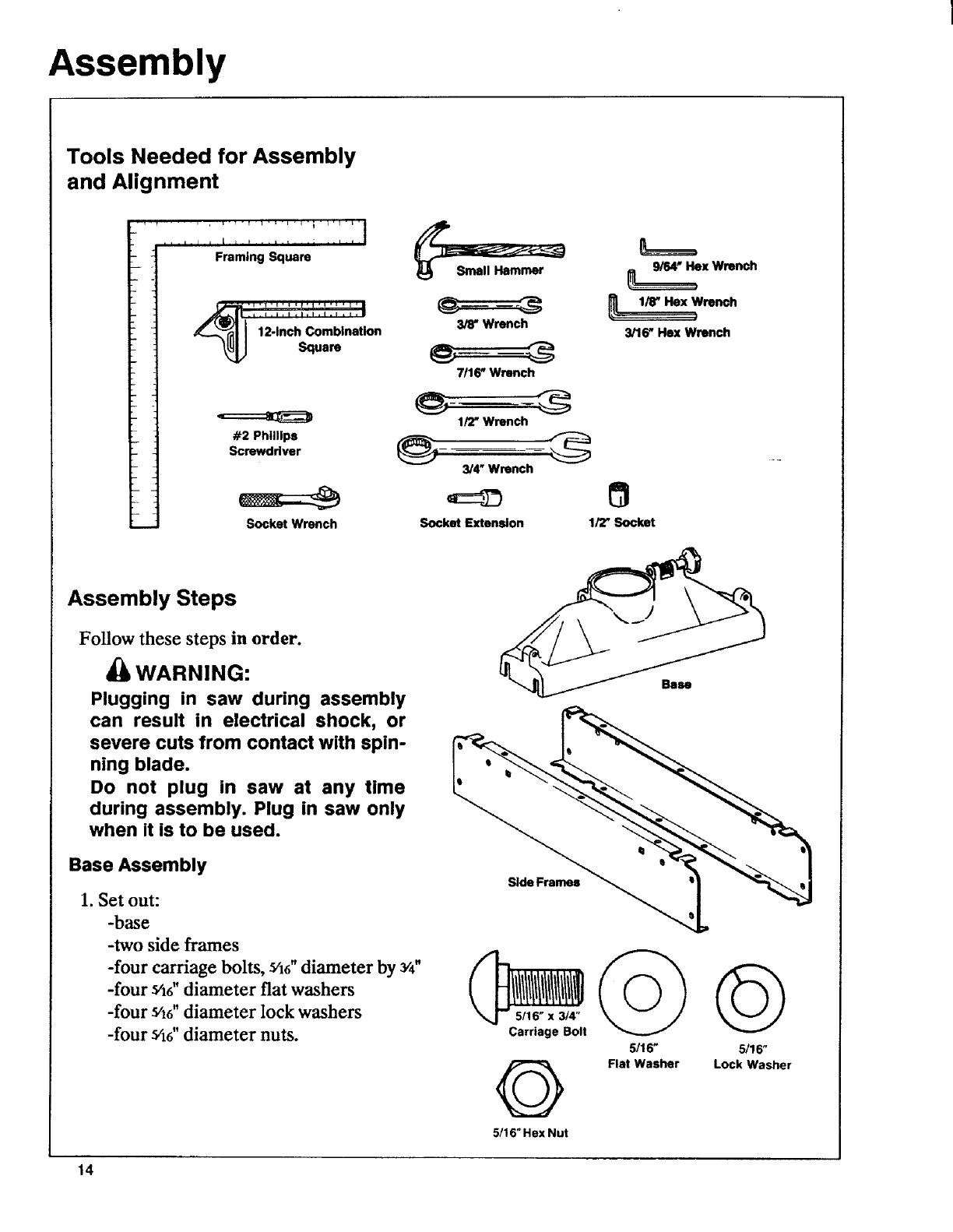
Tools Needed for Assembly
and Alignment
1
.i I F ..t , : ..i i
Framing Square
12-Inch Comblnetlon
Square
#2 PhillipsScrewddver
J
1_
_ ]
.__ Socket Wrench
3/8' Wrench
7/16 _Wrench
1/2" Wrench
3/4" Wrench
Socket Extension 1/'Z' Socket
__x Wrench
1/r Hex Wrench
3/16" Hex Wrench
Assembly Steps
Follow these steps in order.
WARNING:
Plugging in saw during assembly
can result in electrical shock, or
severe cuts from contact with spin-
ning blade.
Do not plug in saw at any time
during assembly. Plug in saw only
when it is to be used.
Base Assembly
1. Set out:
-base
-two side frames
-four carriage bolts, s/16"diameter by 3/4"
-four s'16"diameter flat washers
-four s/16"diameter lock washers
-four _/_6"diameter nuts.
Bilu
Carriage Bolt
5/16" 5/16"
Flat Washer Lock Washer
5/16" Hex Nut
14
Assembly
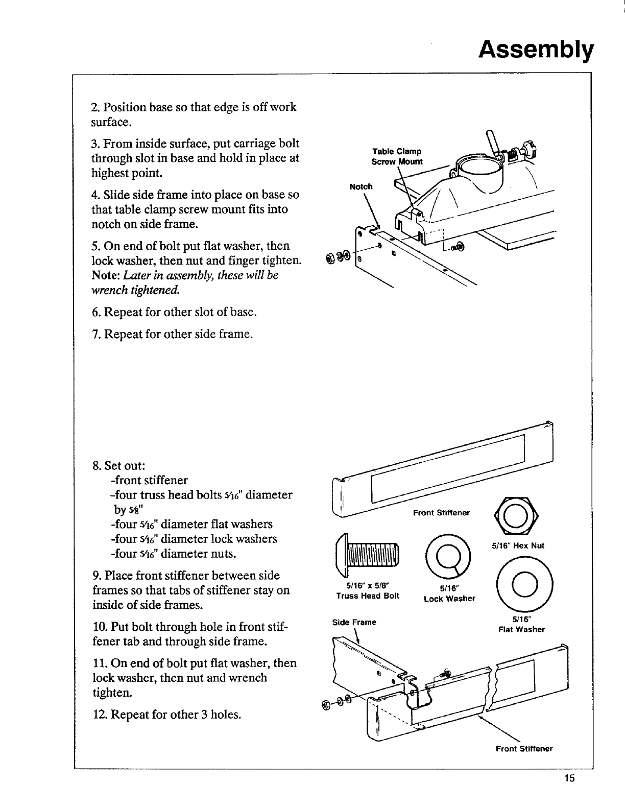
2. Position base so that edge is offwork
surface.
3. From inside surface, put carriage bolt
through slot in base and hold in place at
highest point.
4. Slide side frame into place on base so
that table clamp screw mount fits into
notch on side frame.
5. On end of bolt put fiat washer, then
lock washer, then nut and finger tighten.
Note: Later in assembly, these will be
wrench tightened.
6. Repeat for other slot of base.
7. Repeat for other side frame.
Notch
Table Clamp
Screw Mount
8. Set out:
-front stiffener
-four truss head bolts _/16"diameter
bye"
-four sh6" diameter flat washers
-four 5/16"diameter lock washers
-four s'16"diameter nuts.
9. Place front stiffener between side
frames so that tabs of stiffener stay on
inside of side frames.
10. Put bolt through hole in front stif-
fener tab and through side frame.
11. On end of bolt put flat washer, then
lock washer, then nut and wrench
tighten.
12. Repeat for other 3 holes.
5116" x 518"
Truss Head Bolt
5116" Hex Nut
5/16" _ _ )]
Lock Washer
Side Frame 5/16"
Flat Washer
Front Stiffener
15
Assembly
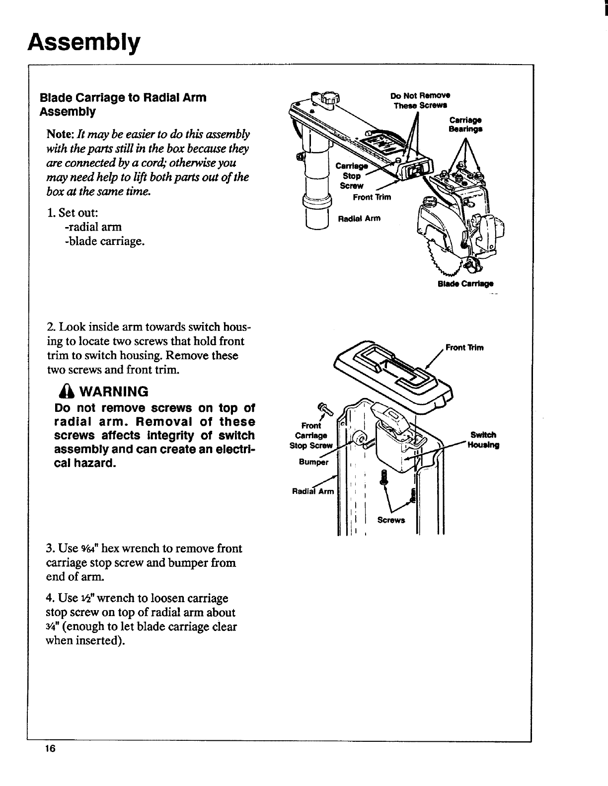
Blade Carriage to Radial Arm
Assembly
Note: It may be easier to do this assembly
with the parts still in the box because they
are connected by a cord,"otherwise you
may need help to lift both parts out of the
box at the same time.
1. Set out:
-radial arm
-blade carriage.
Stop
Screw
FrontTrim
Radial Arm
Do Not Remove
These Screws
Carriage
Bearings
BladeCarriage
2. Look inside arm towards switch hous-
ing to locate two screws that hold front
trim to switch housing. Remove these
two screws and front trim.
WARNING
Do not remove screws on top of
radial arm. Removal of these
screws affects integrity of switch
assembly and can create an electri-
cal hazard.
3. Use 9/64"hex wrench to remove front
carriage stop screw and bumper from
end of arm.
4. Use v2"wrench to loosen carriage
stop screw on top of radial ann about
3/4"(enough to let blade carriage clear
when inserted).
Front
Carriage
Stop
Bumper
Radial Arm
Screwa
Front Trim
Switch
16
Assembly
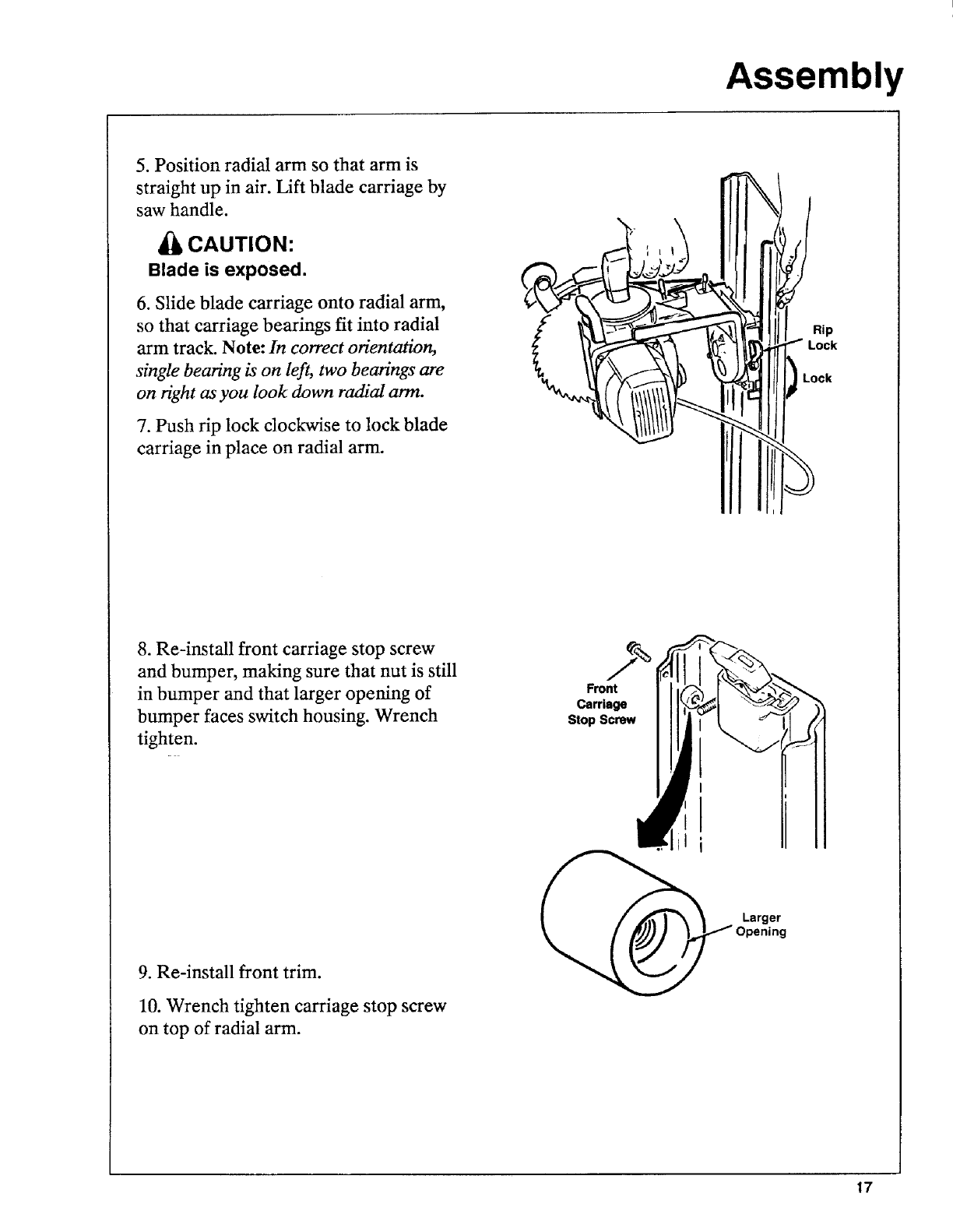
5. Position radial arm so that arm is
straight up in air. Lift blade carriage by
saw handle.
CAUTION:
Blade is exposed.
6. Slide blade carriage onto radial arm,
so that carriage bearings fit into radial
arm track. Note: In correct orientation,
single bearing is on left, two bearings are
on right as you look down radial arm.
7. Push rip lock clockwise to lock blade
carriage in place on radial arm.
r
i
Rip
Lock
Lock
8. Re-install front carriage stop screw
and bumper, making sure that nut is still
in bumper and that larger opening of
bumper faces switch housing. Wrench
tighten.
Front
Carriage
Stop Screw
9. Re-install front trim.
10. Wrench tighten carriage stop screw
on top of radial arm.
il
Larger
Opening
17
Assembly
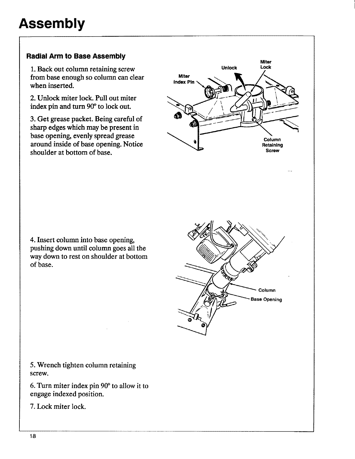
Radial Arm to Base Assembly
1. Back out column retaining screw
from base enough so column can clear
when inserted.
2. Unlock miter lock. Pull out miter
index pin and turn 90°to lock out.
3. Get grease packet. Being careful of
sharp edges which may be present in
base opening, evenly spread grease
around inside of base opening. Notice
shoulder at bottom of base.
Miter
Unlock Lock
Column
Retaining
Screw
4. Insert column into base opening,
pushing down until colunm goes all the
way down to rest on shoulder at bottom
of base.
__?_11;_ Base Opening
5. Wrench tighten column retaining
screw.
6. Turn miter index pin 90°to allow it to
engage indexed position.
7. Lock miter lock.
18
Assembly
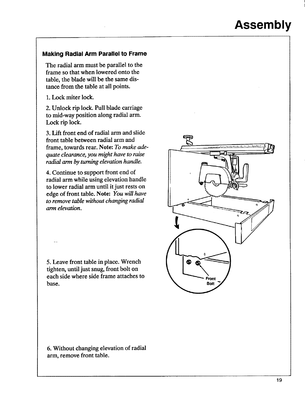
Making Radial Arm Parallel to Frame
The radial arm must be parallel to the
frame so that when lowered onto the
table, the blade will be the same dis-
tance from the table at all points.
1. Lock miter lock.
2. Unlock rip lock. Pull blade carriage
to mid-way position along radial arm.
Lock rip lock.
3. Lift front end of radial arm and slide
front table between radial arm and
frame, towards rear. Note: To make ade-
quate clearance, you might have to raise
radial arm by turning elevation handle.
4. Continue to support front end of
radial arm while using elevation handle
to lower radial arm until it just rests on
edge of front table. Note: You will have
to remove table without changing radial
arm elevation.
!
5. Leave front table in place. Wrench
tighten, until just snug, front bolt on
each side where side frame attaches to
base.
6. Without changing elevation of radial
arm, remove front table.
19
Assembly
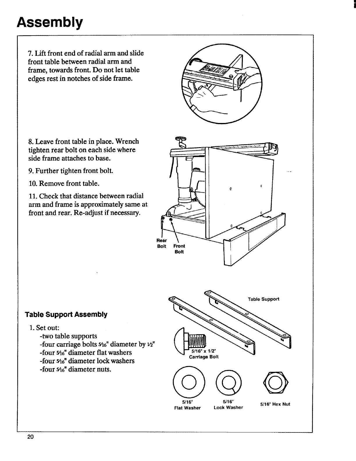
7. Lift front end of radial arm and slide
front table between radial arm and
frame, towards front. Do not let table
edges rest in notches of side frame.
8. Leave front table in place. Wrench
tighten rear bolt on each side where
side frame attaches to base.
9. Further tighten front bolt.
10. Remove front table.
11. Check that distance between radial
arm and frame is approximately same at
front and rear. Re-adjust if necessary.
Rear
Bolt Front
Bolt
Table Support Assembly
1. Set out:
-two table supports
-four carriage bolts s46"diameter by _"
-four s56"diameter flat washers
-four s/t6"diameter lock washers
-four s/t6"diameter nuts.
_5/16" x 1/2"
Carriage Bolt
5116"
Flat Washer
G
5/16"
Lock Washer
Table Support
Q
5116"Hex Nut
20
Assembly
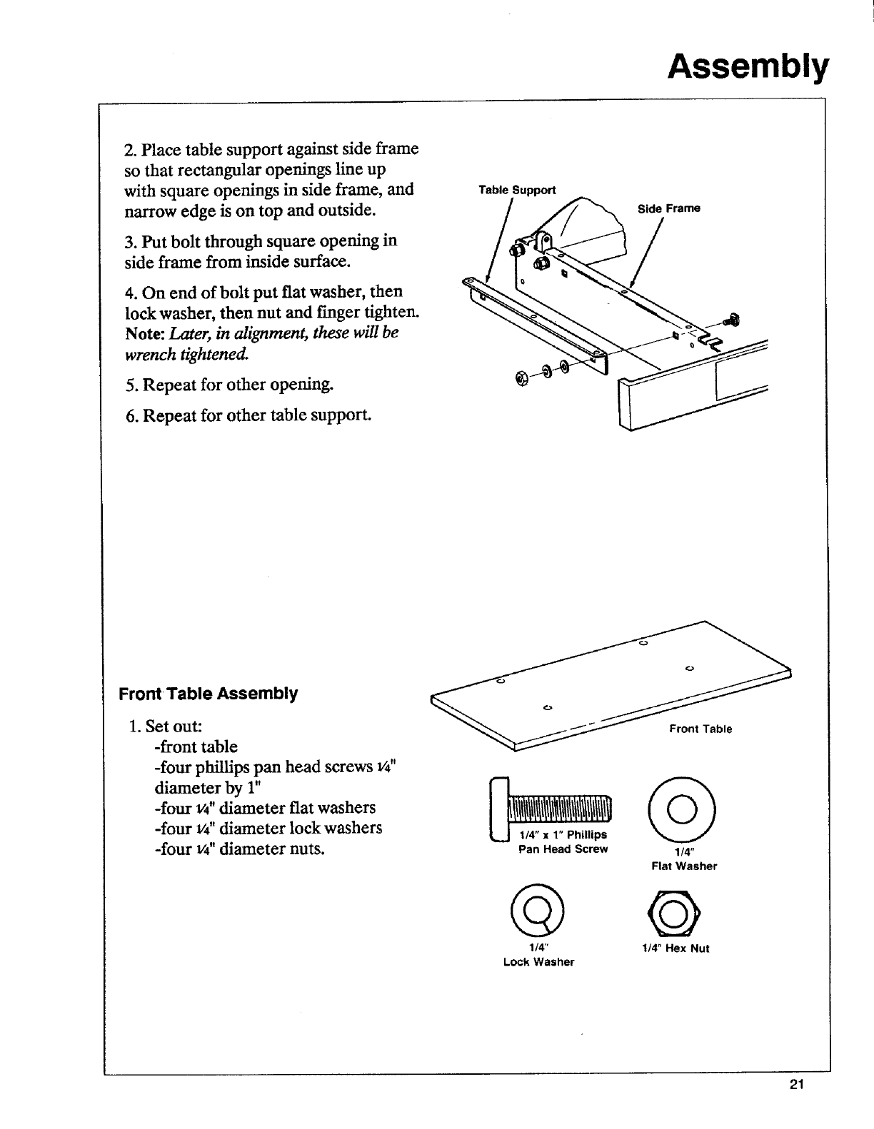
2. Place table support against side frame
so that rectangular openings line up
with square openings in side frame, and
narrow edge is on top and outside.
3. Put bolt through square opening in
side frame from inside surface.
4. On end of bolt put fiat washer, then
lock washer, then nut and finger tighten.
Note: Later, in alignment, these will be
wrench tightened.
5. Repeat for other opening.
6. Repeat for other table support.
Table Support
Side Frame
Front Table Assembly
1. Set out:
-front table
-four phillips pan head screws v4"
diameter by r'
-four v4"diameter fiat washers
-four v4"diameter lock washers
-four 1/4"diameter nuts. Pan Head Screw 1/4"
Flat Washer
© ©
1/4" 1/4" Hex Nut
Lock Washer
21
Assembly
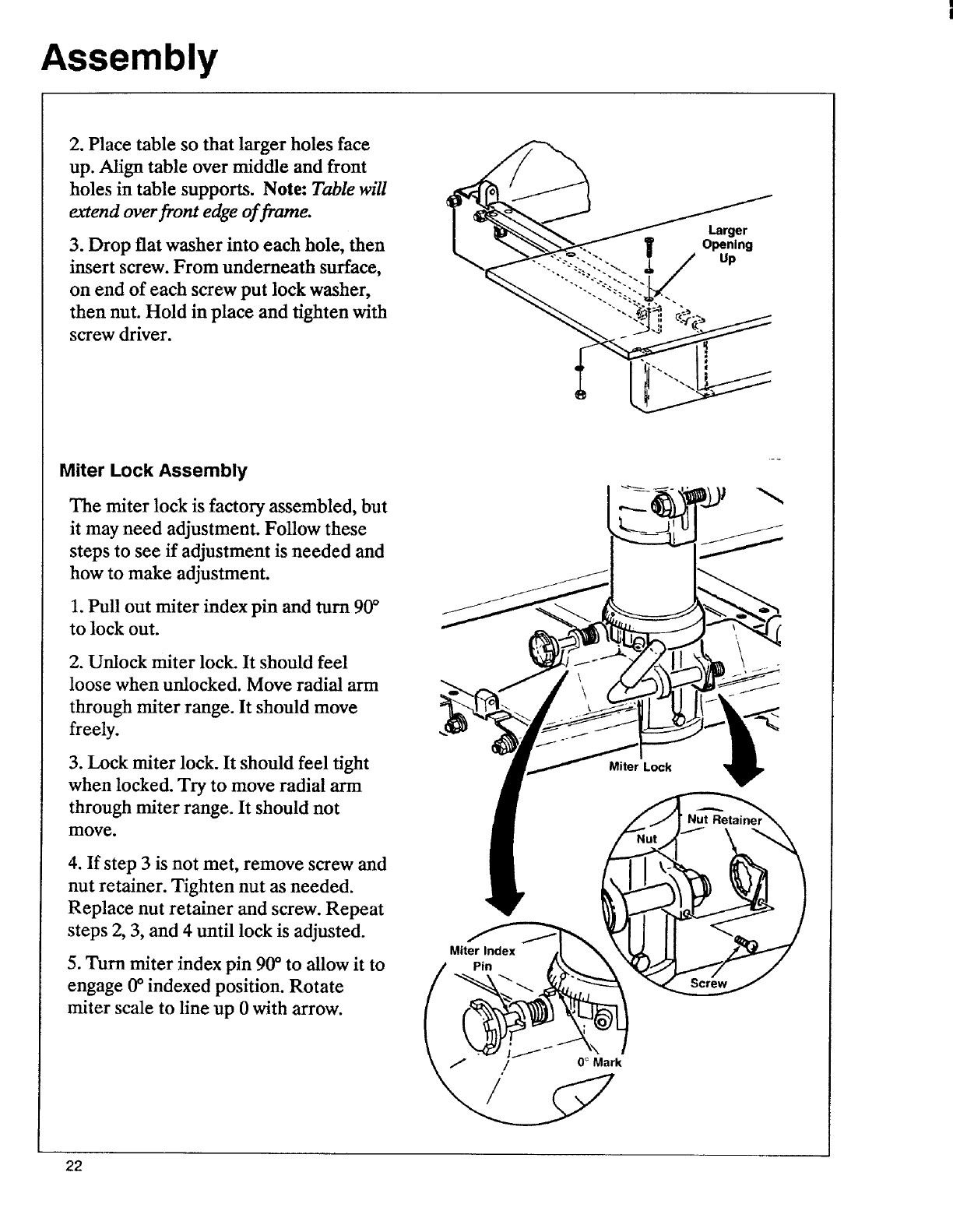
2. Place table so that larger holes face
up. Align table over middle and front
holes in table supports. Note: Table will
extend over front edge of frame.
3. Drop flat washer into each hole, then
insert screw. From underneath surface,
on end of each screw put lock washer,
then nut. Hold in place and tighten with
screw driver.
Larger
IOpening
Up
Miter Lock Assembly
The miter lock is factory assembled, but
it may need adjustment. Follow these
steps to see if adjustment is needed and
how to make adjustment.
1. Pull out miter index pin and turn 90°
to lock out.
2. Unlock miter lock. It should feel
loose when unlocked. Move radial arm
through miter range. It should move
freely.
3. Lock miter lock. It should feel tight
when locked. Try to move radial arm
through miter range. It should not
move.
4. If step 3 is not met, remove screw and
nut retainer. Tighten nut as needed.
Replace nut retainer and screw. Repeat
steps 2, 3, and 4 until lock is adjusted.
5. Turn miter index pin 90°to allow it to
engage 0°indexed position. Rotate
miter scale to line up 0 with arrow.
Miter Index
Pin
Miter Lock
22
Assembly
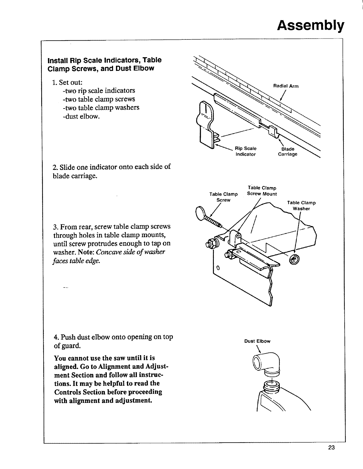
Install Rip Scale Indicators, Table
Clamp Screws, and Dust Elbow
1. Set out:
-two rip scale indicators
-two table clamp screws
-two table clamp washers
-dust elbow.
2. Slide one indicator onto each side of
blade carriage.
3. From rear, screw table clamp screws
through holes in table clamp mounts,
until screw protrudes enough to tap on
washer. Note: Concave side of washer
faces table edge.
. Rip Scale
Indicator
Table Clamp
Screw
/
Table Clamp
Screw Mount
Radial Arm
/
Blade
Carriage
Table Clamp
Washer
4. Push dust elbow onto opening on top
of guard.
You cannot use the saw until it is
aligned. Go to Alignment and Adjust-
ment Section and follow all instruc-
tions. It may be helpful to read the
Controls Section before proceeding
with alignment and adjustment.
Dust Elbow
23
Controls
On-Off Switch
\Rip Scale
Rip Lock
Rip Indicator
Bevel Index Pin
Yellow Key
Control
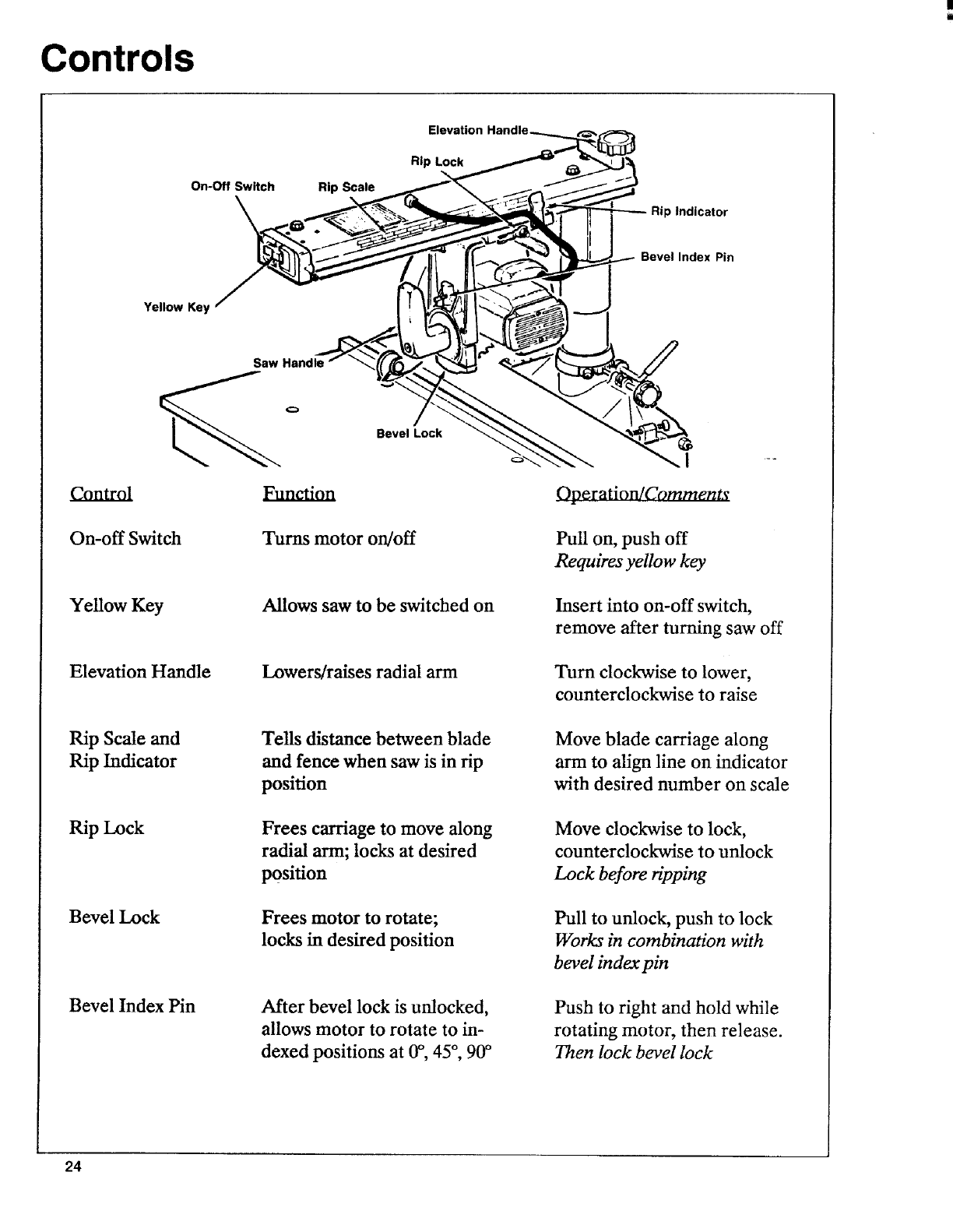
On-off Switch
Yellow Key
Elevation Handle
Rip Scale and
Rip Indicator
Rip Lock
Bevel Lock
Bevel Index Pin
Q
Bevel Lock
Pun_on
Turns motor on/off
Allows saw to be switched on
Lowers/raises radial arm
Tells distance between blade
and fence when saw is in rip
position
Frees carriage to move along
radial arm; locks at desired
position
Frees motor to rotate;
locks in desired position
After bevel lock is unlocked,
allows motor to rotate to in-
dexed positions at 0O,45°, 90°
Operation/Comment_
Pull on, push off
Requires yellow key
Insert into on-off switch,
remove after turning saw off
Turn clockwise to lower,
counterclockwise to raise
Move blade carriage along
arm to align line on indicator
with desired number on scale
Move clockwise to lock,
counterclockwise to unlock
Lock before ripping
Pull to unlock, push to lock
Works in combination whh
bevel index pin
Push to right and hold while
rotating motor, then release.
Then lock bevel lock
24
Controls
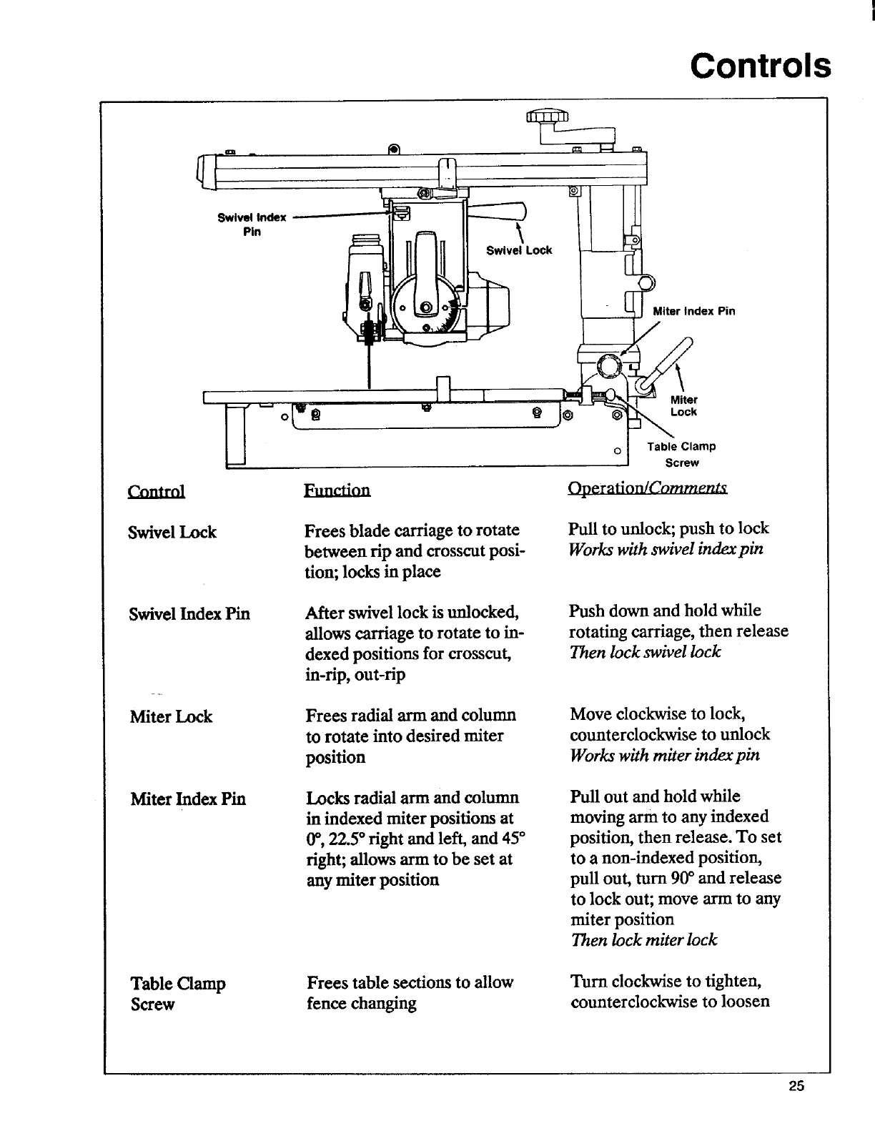
Swivel Index
Pin
Swivel Lock
Miter Index Pin
I
Swivel Lock Frees blade carriage to rotate
between tip and crosscut posi-
tion; locks in place
Swivel Index Pin
Miter Lock
After swivel lock is unlocked,
allows carriage to rotate to in-
dexed positions for crosscut,
in-tip, out-rip
Frees radial arm and column
to rotate into desired miter
position
Miter Index Pin Locks radial arm and column
in indexed miter positiom at
0", 22.5* tight and left, and 45 °
tight; allows arm to be set at
any miter position
QMiter
i_ Lock
oTable Clamp
Screw
Operation/Comments
Pull to unlock; push to lock
Works with swivel index pin
Push down and hold while
rotating carriage, then release
Then lock swivel lock
Move clockwise to lock,
counterclockwise to unlock
Works with miter index pin
Pull out and hold while
moving arm to any indexed
position, then release. To set
to a non-indexed position,
pull out, turn 90°and release
to lock out; move arm to any
miter position
Then lock miter lock
Table Clamp
Screw
Frees table sections to allow
fence changing
Turn clockwise to tighten,
counterclockwise to loosen
25
Controls
\
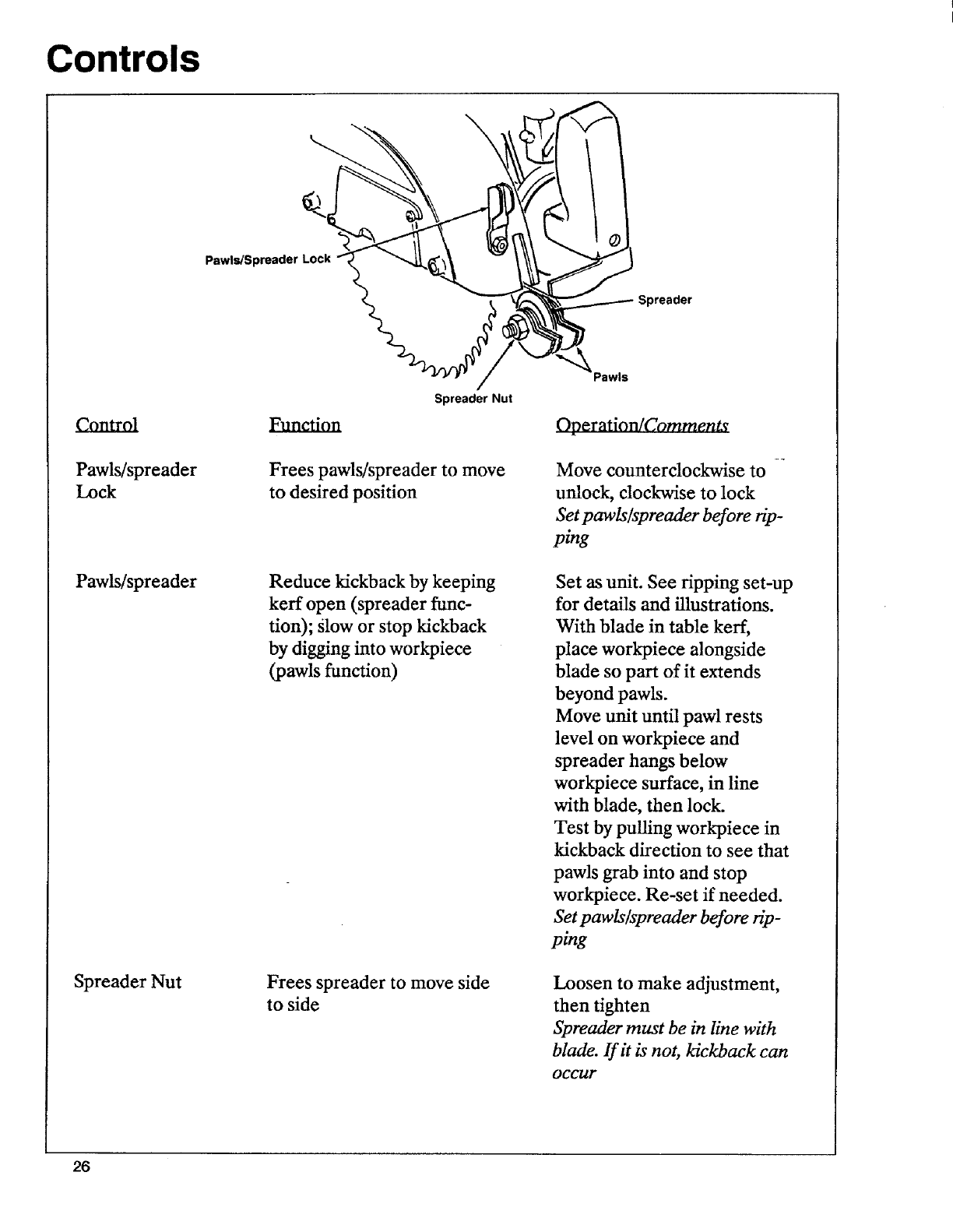
Pawls/Spreader Lock
Pawls/spreader
Lock
Pawl_spreader
Spreader Nut
Spreader Nut
Frees pawls/spreader to move
to desired position
Reduce kickback by keeping
kerr open (spreader func-
tion); Slow or stop kickback
by digging into workpiece
(pawls function)
Frees spreader to move side
to side
Operztion/Comment_
Move counterclockwise to --
unlock, clockwise to lock
Set pawls/spreader before rip-
ping
Set as unit. See ripping set-up
for details and illustrations.
With blade in table kerf,
place workpiece alongside
blade so part of it extends
beyond pawls.
Move unit until pawl rests
level on workpiece and
spreader hangs below
workpiece surface, in line
with blade, then lock.
Test by pulling workpiece in
kickback direction to see that
pawls grab into and stop
workpiece. Re-set if needed.
Set pawls/spreader before rip-
ping
Loosen to make adjustment,
then tighten
Spreader must be in line with
blade. If it is not, kickback can
Occur
26

Controls
,Hold Down Lock
Hold Down
Hold Down Lock
Hold Down
FuneHon
Frees hold down to move to
desired position; locks in
place
Keeps workpiece from flutter-
ing; acts as partial barrier to
blade; acts as sawdust deflec-
tor
Operation/Comment
Move counterclockwise to
unlock, clockwise to lock
Set hold down before ripping
With blade in table kerr and
workpiece against blade,
move hold down until it just
dears workpiece, then lock
Set hold down before ripping
27
Alignment and Adjustment
The saw and blade must be aligned cor-
rectly for two reasons:
1) to make cuts accurate
2) to prevent binding of the blade and
workpiece, which can cause jams, kick-
backs, or thrown workpieces.
Alignment and Adjustment
Steps
The following adjustments must be
made in order before using the saw for
the first time. If you miss an adjustment,
you must go back, make the missed ad-
justment, and repeat all steps from that
point on.
These adjustments are like fine tuning a
piece of equipment. Often, a series of
steps must be repeated more than once
in order to get the adjustment fight.
_WARNING:
Plugging in saw during alignment
can result in severe cuts from con-
tact with spinning blade.
Do not plug in saw at any time
during alignment or adjustment.
Plug In saw only when it is to be
used.
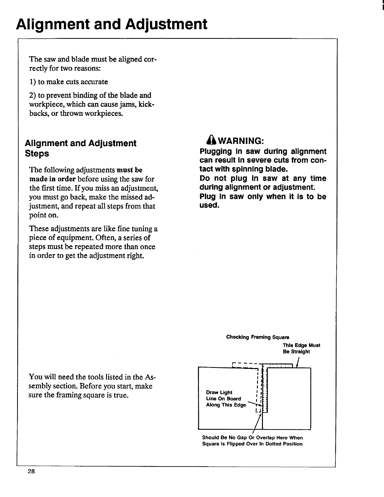
You will need the tools listed in the As-
sembly section. Before you start, make
sure the framing square is true.
Checking Framing Square
r ....
LL --
!
I
I
I
Draw Light I
Line On Board
Along This Edge _/
This Edge Must
Be Straight
/
Should Be No Gap Or Overlap Here When
Square Is Flipped Over In Dotted Position
28
Alignment and Adjustment
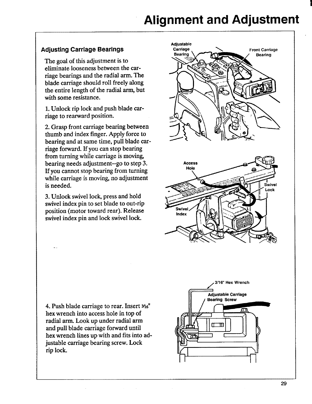
Adjusting Carriage Bearings
The goal of this adjustment is to
eliminate looseness between the car-
riage bearings and the radial arm. The
blade carriage should roll freely along
the entire length of the radial arm, but
with some resistance.
1. Unlock rip lock and push blade car-
riage to rearward position.
2. Grasp front carriage bearing between
thumb and index finger. Apply force to
bearing and at same time, pull blade car-
riage forward. If you can stop bearing
from turning while carriage is moving,
bearing needs adjustment--go to step 3.
If you cannot stop bearing from turning
while carriage is moving, no adjustment
is needed.
3. Unlock swivel lock, press and hold
swivel index pin to set blade to out-rip
position (motor toward rear). Release
swivel index pin and lock swivel lock.
Adiustable
Carriage. "_ Front Carriage
Bearing \Bearing
Access
Hole
Index
Swivel
4. Push blade carriage to rear. Insert aSd'
hex wrench into access hole in top of
radial arm. Look up under radial arm
and pull blade carriage forward until
hex wrench lines up with and fits into ad-
justable carriage bearing screw. Lock
rip lock.
j3116" Hex Wrench
Adjustable Carriage
Bearing Screw
29
Alignment and Adjustment
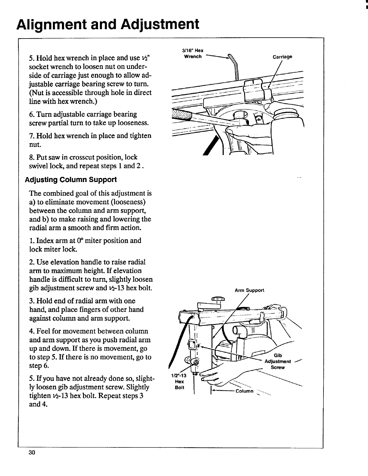
5. Hold hex wrench in place and use vz"
socket wrench to loosen nut on under-
side of carriage just enough to allow ad-
justable carriage beating screw to turn.
(Nut is accessible through hole in direct
line with hex wrench.)
6. Turn adjustable carriage bearing
screw partial turn to take up looseness.
7. Hold hex wrench in place and tighten
nut.
8. Put saw in crosscut position, lock
swivel lock, and repeat steps I and 2.
Adjusting Column Support
The combined goal of this adjustment is
a) to eliminate movement (looseness)
between the column and ann support,
and b) to make raising and lowering the
radial arm a smooth and firm action.
1. Index arm at 0°miter position and
lock miter lock.
2. Use elevation handle to raise radial
arm to maximum height. If elevation
handle is difficult to turn, slightly loosen
gib adjustment screw and 1/2-13hex bolt.
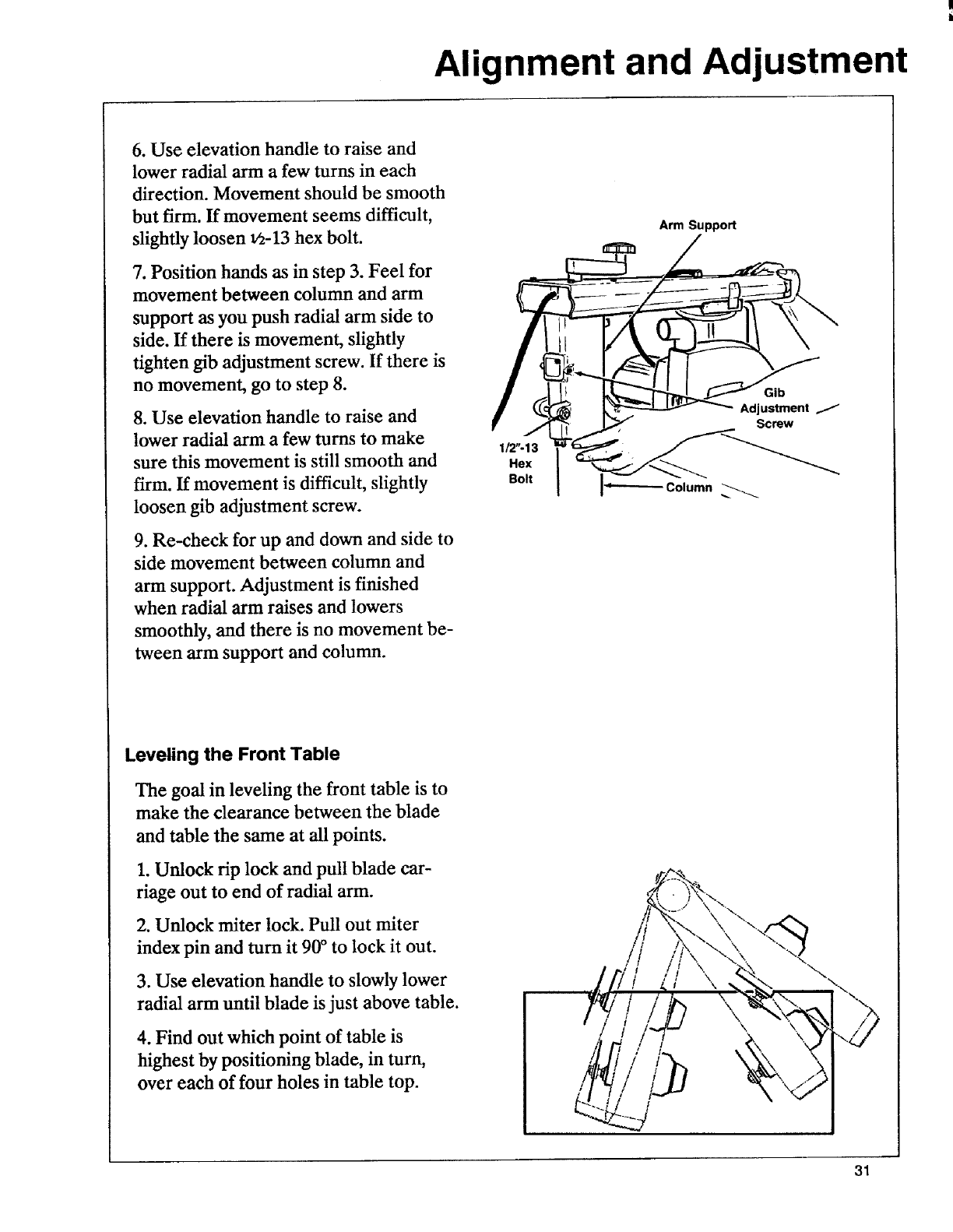
3. Hold end of radial arm with one
hand, and place fingers of other hand
against column and arm support.
4. Feel for movement between column
and arm support as you push radial arm
up and down. If there is movement, go
to step 5. If there is no movement, go to
step 6.
5. If you have not already done so, slight-
ly loosen gib adjustment screw. Slightly
tighten _-13 hex bolt. Repeat steps 3
and 4.
3/16" Hex
Wrench __ ___
Arm Suppo_
Gib
Adjustment --""
Screw
1/2"-13Hex
Bolt Column _._
3O
Alignment and Adjustment
6. Use elevation handle to raise and
lower radial arm a few turns in each
direction. Movement should be smooth
but firm. If movement seems difficult,
slightly loosen 1/2-13hex bolt.
7. Position hands as in step 3. Feel for
movement between column and arm
support as you push radial arm side to
side. If there is movement, slightly
tighten gib adjustment screw. If there is
no movement, go to step 8.
8. Use elevation handle to raise and
lower radial arm a few turns to make
sure this movement is still smooth and
firm. If movement is difficult, slightly
loosen gib adjustment screw.
9. Re-check for up and down and side to
side movement between column and
arm support. Adjustment is finished
when radial arm raises and lowers
smoothly, and there is no movement be-
tween arm support and column.
1/2"-13
Hex
Bolt
Arm Suppo_
Gib
Adjustment 11
Screw
Column
Leveling the Front Table
The goal in leveling the front table is to
make the clearance between the blade
and table the same at all points.
1. Unlock rip lock and pull blade car-
riage out to end of radial arm.
2. Unlock miter lock. Pull out miter
index pin and turn it 90° to lock it out.
3. Use elevation handle to slowly lower
radial arm until blade is just above table.
4. Find out which point of table is
highest by positioning blade, in turn,
over each of four holes in table top.
\
\
t\
\
!\
31
Alignment and Adjustment
5. Start with blade over highest point of
table as found in step 4. Rotate blade by
hand and use elevation handle to slowly
lower radial arm until one tooth just
touches table. Mark this tooth.
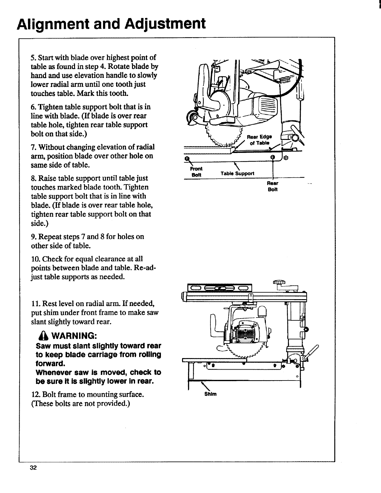
6. Tighten table support bolt that is in
line with blade. (If blade is over rear
table hole, tighten rear table support
bolt on that side.)
7. Without changing elevation of radial
arm,position blade over other hole on
same side of table.
8. Raise table support until table just
touches marked blade tooth. Tighten
table support bolt that is in line with
blade. (If blade is over rear table hole,
tighten rear table support bolt on that
side.)
9. Repeat steps 7 and 8 for holes on
other side of table.
10. Check for equal clearance at all
points between blade and table. Re-ad-
just table supports as needed.
11. Rest level on radial arm. If needed,
put shim under front frame to make saw
slant slightly toward rear.
£k WARNING:
Saw must slant slightly toward rear
to keep blade carriage from rolling
forward.
Whenever saw is moved, check to
be sure it is slightly lower in rear.
12. Bolt frame to mounting surface.
(These bolts are not provided.)
O
Front
Bolt Table Support
Rear
Bolt
I
-o(-0
\Shlm
32
Alignment and Adjustment
Squaring Blade Crosscut Travel
The goal of this adjustment is to make
accurate crosscuts. To do so, the blade
must travel along the radial arm, per-
pendicular to the fence, otherwise,
there will be a slight miter angle in all
crosscuts.
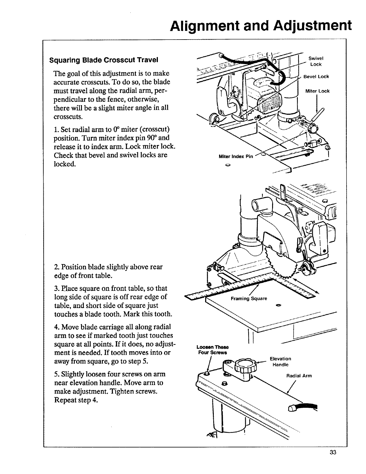
1. Set radial arm to 0°miter (crosscut)
position. Turn miter index pin 90°and
release it to index arm. Lock miter lock.
Check that bevel and swivel locks are
locked.
swivo,
F_"_ II_._zlr t_'_ --. _'_-SX.lf I Miter Lock
........
2. Position blade slightly above rear
edge of front table.
3. P_lace square on front table, so that
long side of square is off rear edge of
table, and short side of square just
touches a blade tooth. Mark this tooth.
4. Move blade carriage all along radial
arm to see if marked tooth just touches
square at all points. If it does, no adjust-
ment is needed. If tooth moves into or
away from square, go to step 5.
5. Slightly loosen four screws on arm
near elevation handle. Move arm to
make adjustment. Tighten screws.
Repeat step 4.
Loosen These
Four Screws
Framing Square
€=,
Elevation
Handle
Radial Arm
33
Alignment and Adjustment
Squaring Blade to Table
The goal of this adjustment is to make
the blade perpendicular to the table so
that cuts will be accurate; otherwise all
cuts will have a slight bevel angle. The
bevel scale will also be adjusted.
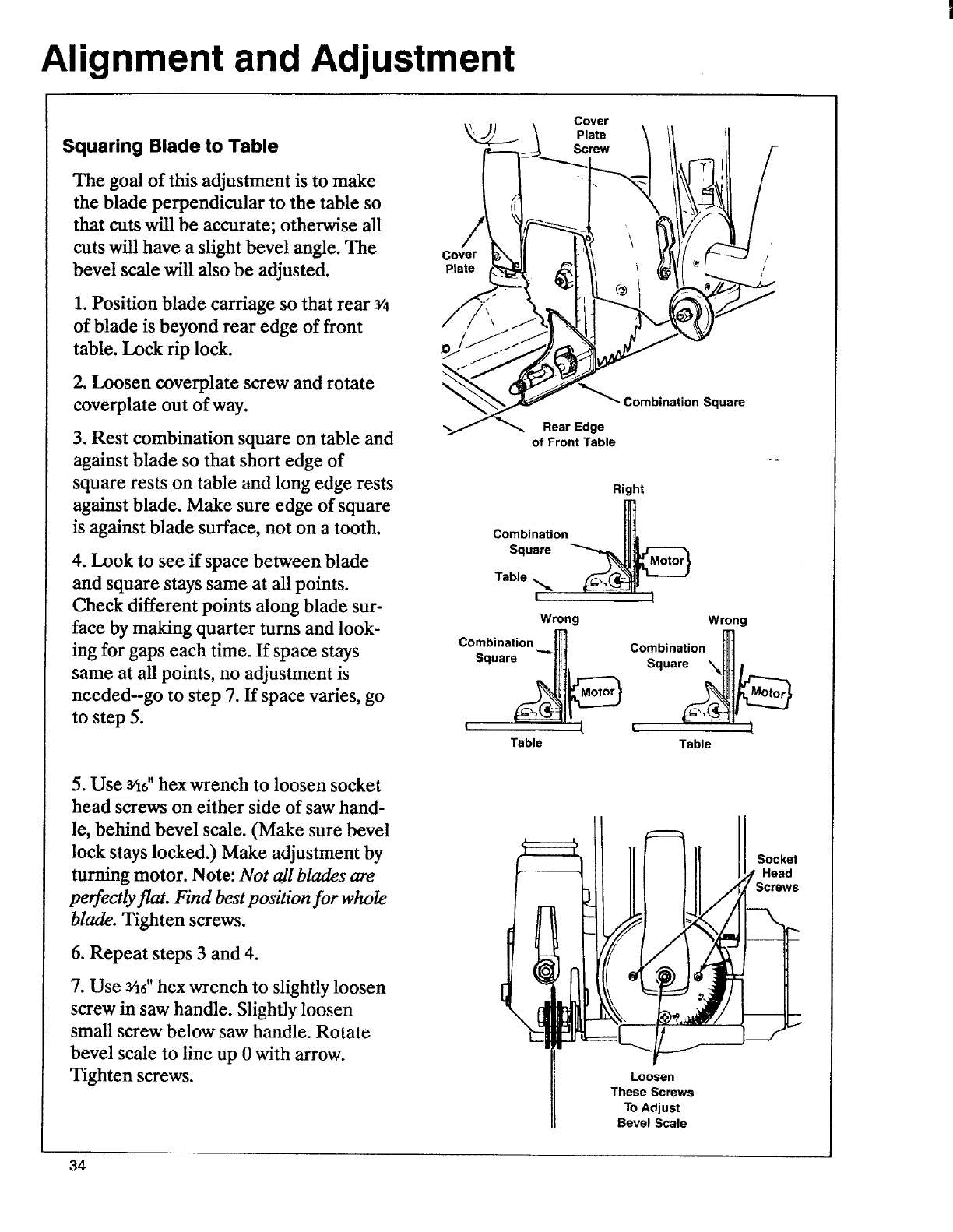
1. Position blade carriage so that rear 3/4
of blade is beyond rear edge of front
table. Lock rip lock.
2. Loosen coverplate screw and rotate
coverplate out of way.
3. Rest combination square on table and
against blade so that short edge of
square rests on table and long edge rests
against blade. Make sure edge of square
is against blade surface, not on a tooth.
4. Look to see if space between blade
and square stays same at all points.
Check different points along blade sur-
face by making quarter turns and look-
ing for gaps each time. If space stays
same at all points, no adjustment is
needed--go to step 7. If space varies, go
to step 5.
5. Use 3/16"hex wrench to loosen socket
head screws on either side of saw hand-
le, behind bevel scale. (Make sure bevel
lock stays locked.) Make adjustment by
turning motor. Note: Not all blades are
perfectly flat. Find best position for whole
blade. Tighten screws.
6. Repeat steps 3 and 4.
7. Use 3/16'' hex wrench to slightly loosen
screw in saw handle. Slightly loosen
small screw below saw handle. Rotate
bevel scale to line up 0 with arrow.
Tighten screws.
Plate
Cover
Plate
_""_ Combination Square
Rear Edge
of Front Table
Right
Combination
Square
Table
Wrong Wrong
Combination _]
Square_l_ C°sb_nati°n__
I'n t. I
Table Table
Socket
Head
Loosen
These Screws
To Adjust
Bevel Scale
34
Alignment and Adjustment
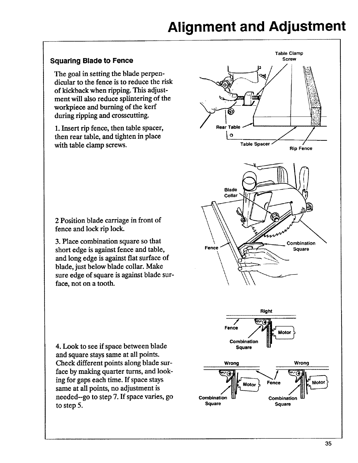
Squaring Blade to Fence
The goal in setting the blade perpen-
dicular to the fence is to reduce the risk
of kickback when ripping. This adjust-
ment will also reduce splintering of the
workpiece and burning of the kerr
during ripping and crosscutting.
1. Insert rip fence, then table spacer,
then rear table, and tighten in place
with table clamp screws.
/
Table Clamp
Screw
Rear Table
Io / J
Table Spacer / /
Rip Fence
2 Position blade carriage in front of
fence and lock rip lock.
3. Place combination square so that
short edge is against fence and table,
and long edge is against flat surface of
blade, just below blade collar. Make
sure edge of square is against blade sur-
face, not on a tooth.
Right
Fence
4. Look to see if space between blade
and square stays same at all points.
Check different points along blade sur-
face by making quarter turns, and look-
ing for gaps each time. If space stays
same at all points, no adjustment is
needed-go to step 7. If space varies, go
to step 5.
Combination
Square
Wrong
Combination
Square
Combination
Square
35
Alignment and Adjustment
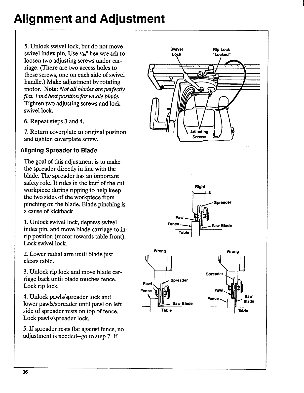
5. Unlock swivel lock, but do not move
swivel index pin. Use Yi6"hex wrench to
loosen two adjusting screws under ear-
riage. _ere are two access holes to
these screws, one on each side of swivel
handle.) Make adjustment by rotating
motor. Note: Not all blades are perfectly
flat. Find best position for whole blade.
Tighten two adjusting screws and lock
swivel lock.
6. Repeat steps 3 and 4.
7. Return coverplate to original position
and tighten coverplate screw.
Aligning Spreader to Blade
The goal of this adjustment is to make
the spreader directly in line with the
blade. The spreader has an important
safety role. It rides in the kerf of the cut
workpieee during ripping to help keep
the two sides of the workpiece from
pinching on the blade. Blade pinching is
a cause of kickback.
1. Unlock swivel lock, depress swivel
index pin, and move blade carriage to in-
rip position (motor towards table front).
Lock swivel lock.
2. Lower radial arm until blade just
clears table.
3. Unlock rip lock and move blade car-
riage back until blade touches fence.
Lock rip lock.
4. Unlock pawls/spreader lock and
lower pawls/spreader until pawl on left
side of spreader rests on top of fence.
Lock pawls/spreader lock.
5. If spreader rests flat against fence, no
adjustment is needed--go to step 7. If
Pawl
Fence
Wrong
Table
Swivel Rip Lock
Lock "Locked"
Right
_Spreader
..SawB,. e
T.bleI I
Wrong
Spreader
Spreader
Pawl.
Fence
Saw Blade
Saw
|lade
Table
36
Alignment and Adjustment
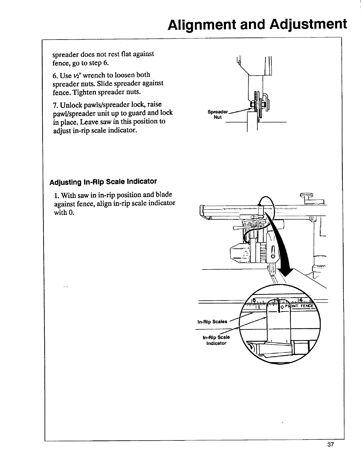
spreader does not rest flat against
fence, go to step 6.
6. Use v_"wrench to loosen both
spreader nuts. Slide spreader against
fence. Tighten spreader nuts.
7. Unlock pawls/spreader lock, raise
paw!/spreader unit up to guard and lock
in place. Leave saw in this position to
adjust in-rip scale indicator.
Spreader_
Adjusting In-Rip Scale Indicator
1. With saw in in-rip position and blade
against fence, align in-rip scale indicator
with O.
37
Alignment and Adjustment
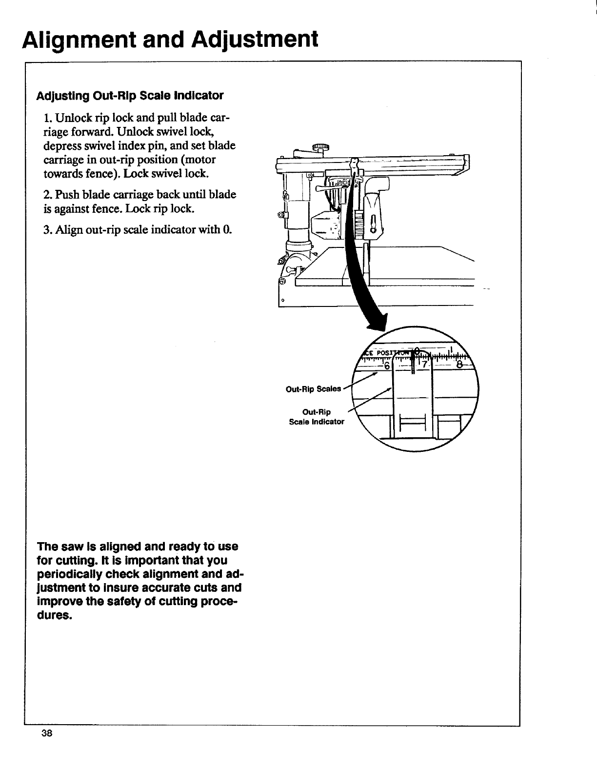
Adjusting Out-Rip Scale Indicator
1. Unlock rip lock and pull blade car-
riage forward. Unlock swivel lock,
depress swivel index pin, and set blade
carriage in out-rip position (motor
towards fence). Lock swivel lock.
2. Push blade carriage back until blade
is against fence. Lock rip lock.
3. Align out-rip scale indicator with 0.
9
Out-Ril:
Out-Rip
Scale Indicator
The saw is aligned and ready to use
for cutting. It is important that you
periodically check alignment and ad-
justment to insure accurate cuts and
improve the safety of cutting proce-
dures.
38
Electrical Connections
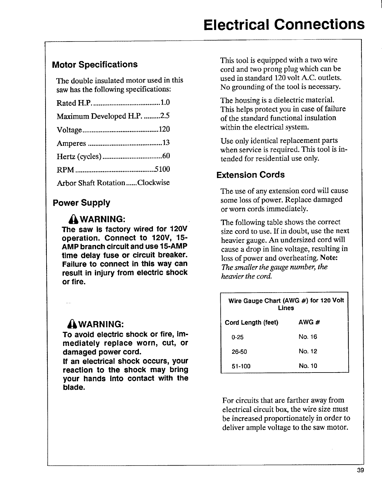
Motor Specifications
The double insulated motor used in this
saw has the following specifications:
Rated H.P ...................................... 1.0
Maximum Developed H.P .......... 2.5
Voltage .......................................... 120
Amperes ......................................... 13
Hertz (cycles) ................................. 60
RPM ............................................ 5100
Arbor Shaft Rotation ...... Clockwise
Power Supply
_WARNING:
The saw is factory wired for 120V
operation. Connect to 120V, 15-
AMP branch circuit and use 15-AMP
time delay fuse or circuit breaker.
Failure to connect in this way can
result in injury from electric shock
or fire.
This tool is equipped with a two wire
cord and two prong plug which can be
used in standard 120 volt A.C. outlets.
No grounding of the tool is necessary.
The housing is a dielectric material.
This helps protect you in case of failure
of the standard functional insulation
within the electrical system.
Use only identical replacement parts
when service is required. This tool is in-
tended for residential use only.
Extension Cords
The use of any extension cord will cause
some loss of power. Replace damaged
or worn cords immediately.
The following table shows the correct
size cord to use. If in doubt, use the next
heavier gauge. An undersized cord will
cause a drop in line voltage, resulting in
loss of power and overheating. Note:
The smaller the gauge number, the
heavier the cord.
_WARNING:
To avoid electric shock or fire, im-
mediately replace worn, cut, or
damaged power cord.
If an electrical shock occurs, your
reaction to the shock may bring
your hands into contact with the
blade.
Wire Gauge Chart (AWG #) for 120 Volt
Lines
Cord Length (feet) AWG #
0-25 No. 16
26-50 No. 12
51-100 No. 10
For circuits that are farther away from
electrical circuit box, the wire size must
be increased proportionately in order to
deliver ample voltage to the saw motor.
39
Crosscutting
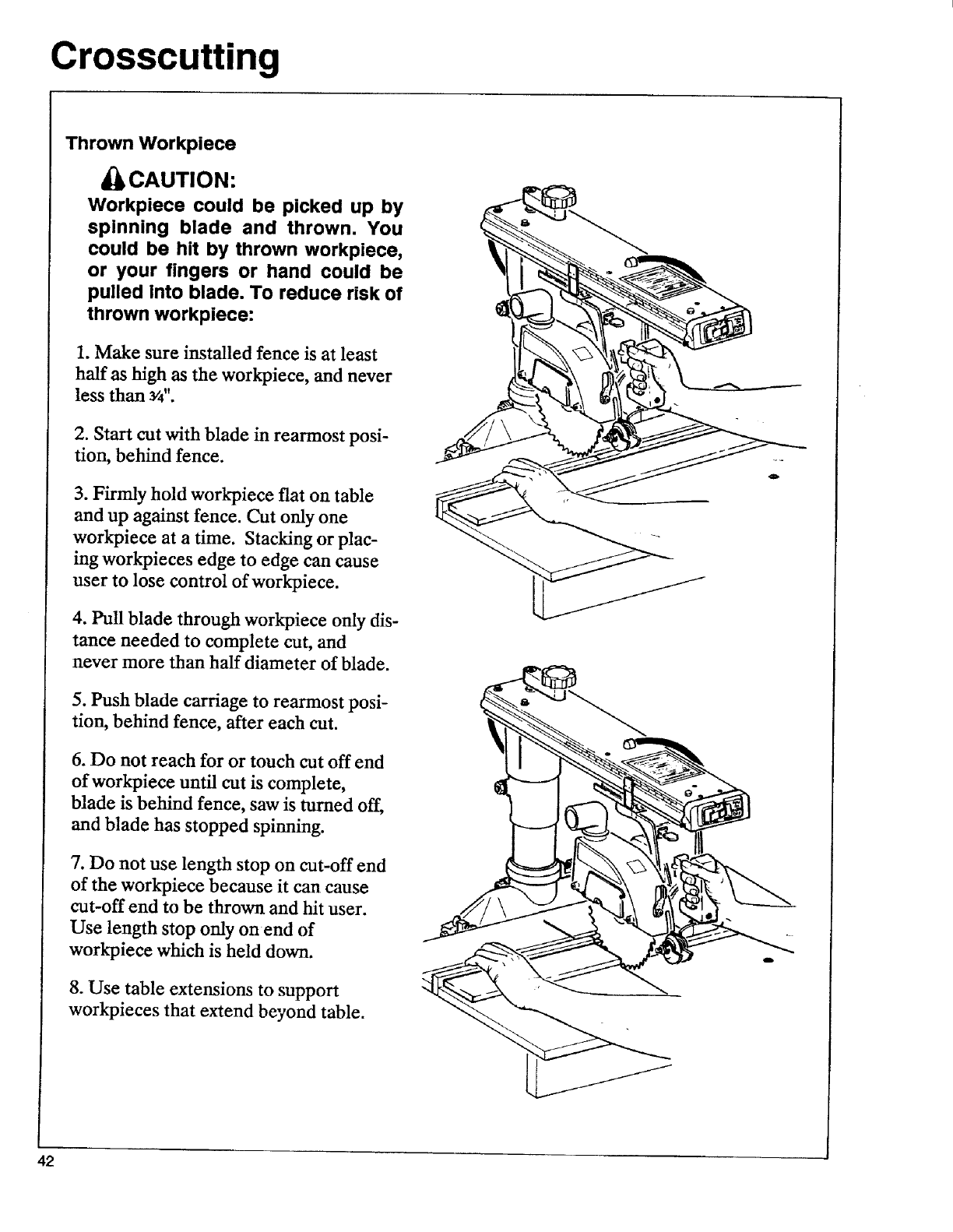
Thrown Workpiece
_CAUTION:
Workpiece could be picked up by
spinning blade and thrown. You
could be hit by thrown workpiece,
or your fingers or hand could be
pulled into blade. To reduce risk of
thrown workpiece:
1. Make sure installed fence is at least
half as high as the workpiece, and never
less than s/4".
2. Start cut with blade in rearmost posi-
don, behind fence.
3. Firmly hold workpiece fiat on table
and up against fence. Cut only one
workpiece at a time. Stacking or plac-
ing workpieces edge to edge can cause
user to lose control of workpiece.
4. Pull blade through workpiece only dis-
tance needed to complete cut, and
never more than half diameter of blade.
5. Push blade carriage to rearmost posi-
tion, behind fence, after each cut.
6. Do not reach for or touch cut off end
of workpiece until cut is complete,
blade is behind fence, saw is turned off,
and blade has stopped spinning.
7. Do not use length stop on cut-off end
of the workpiece because it can cause
cut-off end to be thrown and hit user.
Use length stop only on end of
workpiece which is held down.
8. Use table extensions to support
workpieces that extend beyond table.
42
Crosscutting
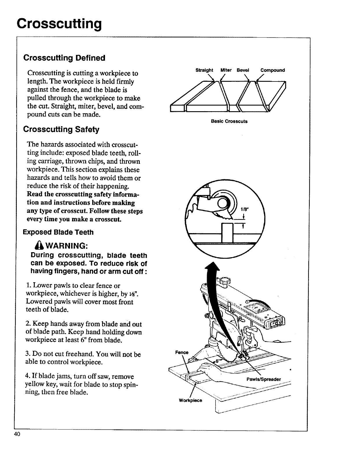
Crosscutting Defined
Crosscutting is cutting a workpiece to
length. The workpiece is held firmly
against the fence, and the blade is
pulled through the workpiece to make
the cut. Straight, miter, bevel, and com-
pound cuts can be made.
Crosscutting Safety
The hazards associated with crosscut-
ring include: exposed blade teeth, roll-
ing carriage, thrown chips, and thrown
workpiece. This section explains these
hazards and tells how to avoid them or
reduce the risk of their happening.
Read the crosscutting safety informa-
tion and instructions before making
any type of crosscut. Follow these steps
every time you make a crosscut.
Exposed Blade Teeth
WARNING:
During crosscutting, blade teeth
can be exposed. To reduce risk of
having fingers, hand or arm cut off :
1. Lower pawls to clear fence or
workpiece, whichever is higher, by r,".
Lowered pawls will cover most front
teeth of blade.
2. Keep hands away from blade and out
of blade path. Keep hand holding down
workpiece at least 6" from blade.
3. Do not cut freehand. You will not be
able to control workpiece.
4. If blade jams, turn off saw, remove
yellow key, wait for blade to stop spin-
ning, then free blade.
Straight Miter Bevel Compound
Basic Crosscuts
Fence
Pawls/Spreader
Workplece
4O
Crosscutting
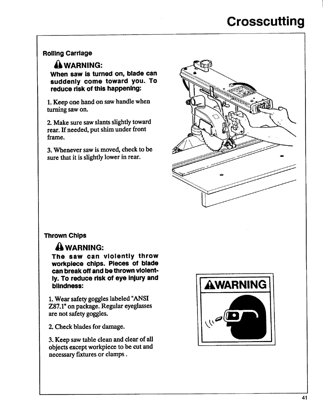
Rolling Carriage
_WARNING:
When saw is turned on, blade can
suddenly come toward you. To
reduce risk of this happening:
1. Keep one hand on sawhandle when
turningsaw on.
2. Make sure saw slants slightly toward
rear. If needed, put shim under front
frame.
3. Whenever saw is moved, check to be
sure that it is slightly lower in rear.
Thrown Chips
_WARNING:
The saw can violently throw
workplece chips. Pieces of blade
can break off and be thrown violent-
ly. To reduce risk of eye Injury and
blindness:
1.Wear safety goggles labeled "ANSI
Z87.1" on package. Regular eyeglasses
are not safety goggles.
2. Check blades for damage.
3. Keep saw table clean and clear of all
objects except workpiece to be cut and
necessary fixtures or clamps.
kWARNING
41
Crosscutting
Crossscutting Checklist
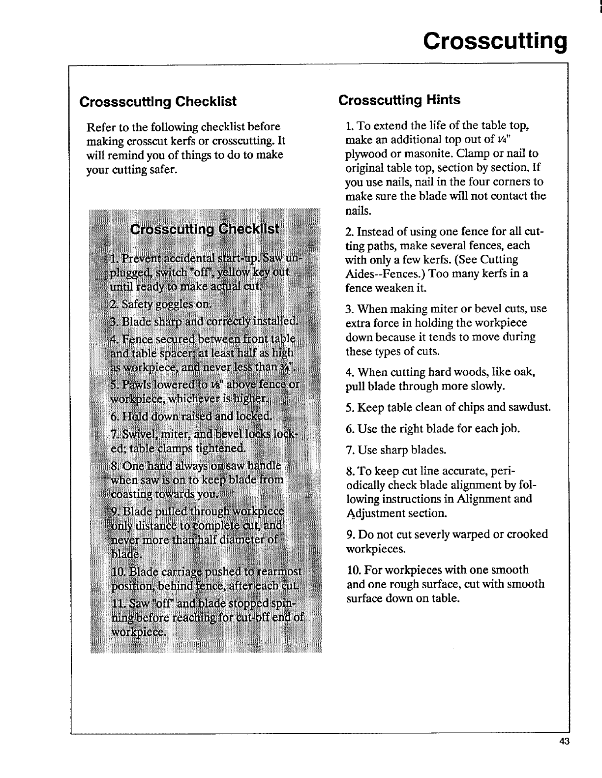
Refer to the following checklist before
making crosscut kerfs or crosscutting. It
will remind you of things to do to make
your cutting safer.
Crosscutting Hints
1. To extend the life of the table top,
make an additional top out of v4"
plywood or masonite. Clamp or nail to
original table top, section by section. If
you use nails, nail in the four corners to
make sure the blade will not contact the
nails.
2. Instead of using one fence for all cut-
ring paths, make several fences, each
with only a few kerfs. (See Cutting
Aides--Fences.) Too many kerfs in a
fence weaken it.
3. When making miter or bevel cuts, use
extra force in holding the workpiece
down because it tends to move during
these types of cuts.
4. When cutting hard woods, like oak,
pull blade through more slowly.
5. Keep table clean of chips and sawdust.
6. Use the right blade for each job.
7. Use sharp blades.
8. To keep cut line accurate, peri-
odically check blade alignment by fol-
lowing instructions in Alignment and
Adjustment section.
9. Do not cut severly warped or crooked
workpieces.
10. For work_ieces with one smooth
and one rough surface, cut with smooth
surface down on table.
43
Crosscutting
Kerfs
A kerf or shallow cut is needed in the
table and fence to serve as a path for the
blade and to ensure that the blade cuts
all the way through the workpiece. A
kerr is needed for each different cutting
path.
Follow these steps to make ap-
proximately v_g' deep kerf:
1. Check that saw is unplugged, switch is
"off' and yellow key is out.
2. Put fence between front table and
spacer board. Tighten table clamps.
3. Set desired bevel angle. Move arm to
desired miter position. Lock bevel,
miter and swivel locks.
4. Unlock rip lock and push blade car-
riage to rearmost position, behind fence.
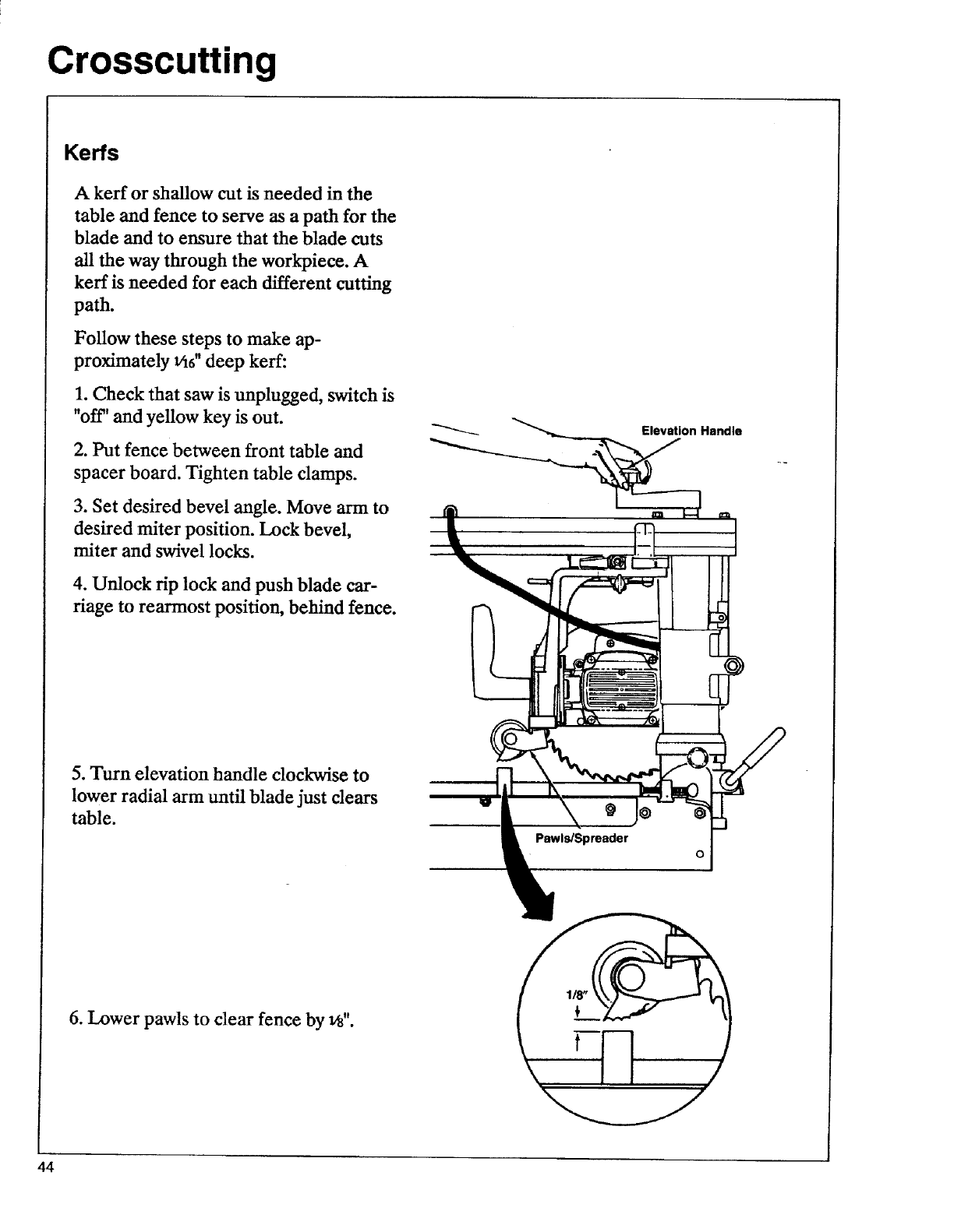
5. Turn elevation handle clockwise to
lower radial arm until blade just dears
table.
Elevation Handle
0
6. Lower pawls to clear fence by _".
44
Crosscutting
7. Plug saw in.
8. Put yellow key in switch.
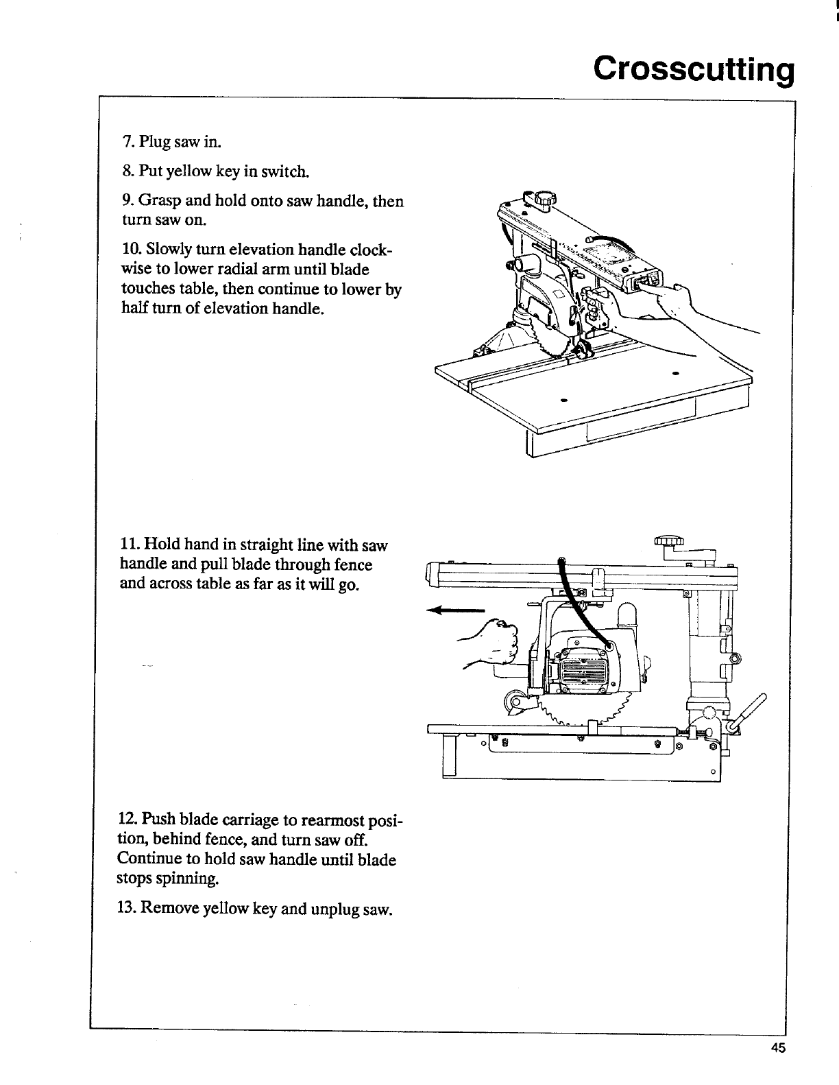
9. Grasp and hold onto saw handle, then
tam saw on.
10. Slowly turn elevation handle dock-
wise to lower radial arm until blade
touches table, then continue to lower by
half turn of elevation handle.
11. Hold hand in straight line with saw
handle and pull blade through fence
and across table as far as it will go.
12. Push blade carriage to rearmost posi-
tion, behind fence, and turn saw off.
Continue to hold saw handle until blade
stops spinning.
13. Remove yellow key and unplug saw.
45
Crosscutting
Making Straight and Miter
Crosscuts
Follow these steps to make straight and
miter crosscuts. Note: There are four in-
dexed miter positions, 0°, 22_ °right and
left, and 45°right. To move to an indexed
position, unlock miter lock and pull and
hold out miter index pin while moving
arm to desired angle. Release miter index
pin and lock miter lock. To move to a
non-indexed position, unlock miter lock,
pull out miter index pin and turn it 90°to
lock it out. Move arm to desired angle
and lock miter lock.
1. Check that saw is unplugged, switch is
"off' and yellow key is out.
2. Put fence between front table and
spacer board. Tighten table clamps.
3. Move arm to desired miter position.
Lock miter, bevel and swivel locks.
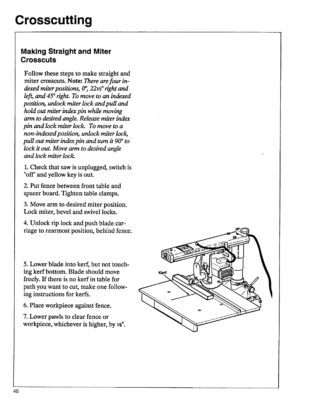
4. Unlock rip lock and push blade car-
riage to rearmost position, behind fence.
5. Lower blade into kerr, but not touch-
ing kerr bottom. Blade should move
freely. If there is no kerf in table for
path you want to cut, make one follow-
ing instructions for kerfs.
6. Place workpiece against fence.
7. Lower pawls to clear fence or
workpiece, whichever is higher, by v_".
Kerr
46
Crosscutting
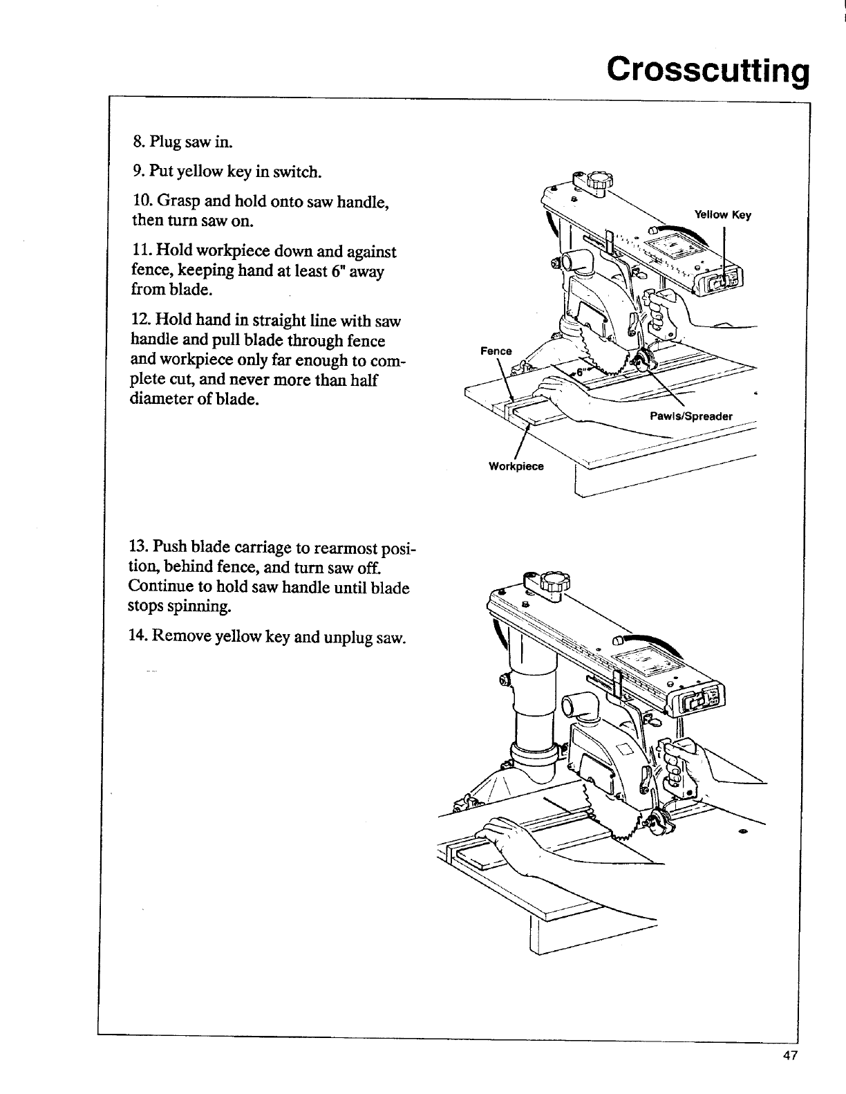
8. Plug saw in.
9. Put yellow key in switch.
10. Grasp and hold onto saw handle,
then turn saw on.
11. Hold workpiece down and against
fence, keeping hand at least 6" away
from blade.
12. Hold hand in straight line with saw
handle and pull blade through fence
and workpiece only far enough to com-
plete cut, and never more than half
diameter of blade.
Fence
Workpiece
Yellow Key
13. Push blade carriage to rearmost posi-
tion, behind fence, and turn saw off.
Continue to hold saw handle until blade
stops spinning.
14. Remove yellow key and unplug saw.
47

Crosscutting
Making Bevel and Compound
Crosscuts
Follow these steps to make bevel and
compound crosscuts.
1. Check that saw is unplugged, switch is
"off' and yellow key is out.
2. Put fence between front table and
spacer board. Tighten table clamps.
3. Turn elevation handle counter-clock-
wise to raise radial arm so blade will not
jam into table top when bevel is set.
4. Unlock bevel lock. Slide bevel index
pin to right and set bevel angle. Release
pin and lock bevel lock.
Bevel Index Pin
Bevel Lock
5. Move ann to desired miter position.
Lock miter and swivel locks.
6. Unlock rip lock and push blade car-
riage to rearmost position, behind
fence.
7. Lower blade into kerf, but not touch-
ing kerf bottom. Blade should move
freely. If there is no kerr in table for
path you want to cut, make one follow-
ing instructions for kerfs.
8. Place workpiece against fence.
Lock
Miter Index Pin
48

Crosscutting
9. Lower pawls to clear fence or
workpiece, whichever is higher, by _".
10. Put yellow key in switch.
11. Grasp and hold onto saw handle,
then turn saw on.
12. Hold workpiece down and against
fence, keeping hand at least 6" away
from blade.
13. Hold hand in straight line with saw
handle and pull blade through fence
and work_iece only far enough to com-
plete cut, and never more than half
diameter of blade.
14. Push blade carriage to rearmost posi-
tion, behind fence, and turn saw off.
Continue to hold saw handle until blade
stops spinning.
15. Remove yellow key and unplug saw.
Repetitive Crosscutting
Repetitive crosscutting is the repeated
and continuous cutting of many pieces
of lumber to the same length with the
saw placed in the crosscut position.
See Accessories for information on a
lower blade guard for use in repetitive
90°(0 miter) crosscutting.
Use a carriage stop to define distance
needed to pull blade through to com-
plete each cut. To make a carriage stop:
1. Cut piece of lxl lumber to 2" long.
2. Clamp piece on left inside surface of
the radial arm, so that blade carriage
stops at distance needed to complete
cut. Check that clamp does not interfere
with hand grip on saw handle. Re-adjust
if needed.
Bevel Angle
49
Ripping
Ripping Defined
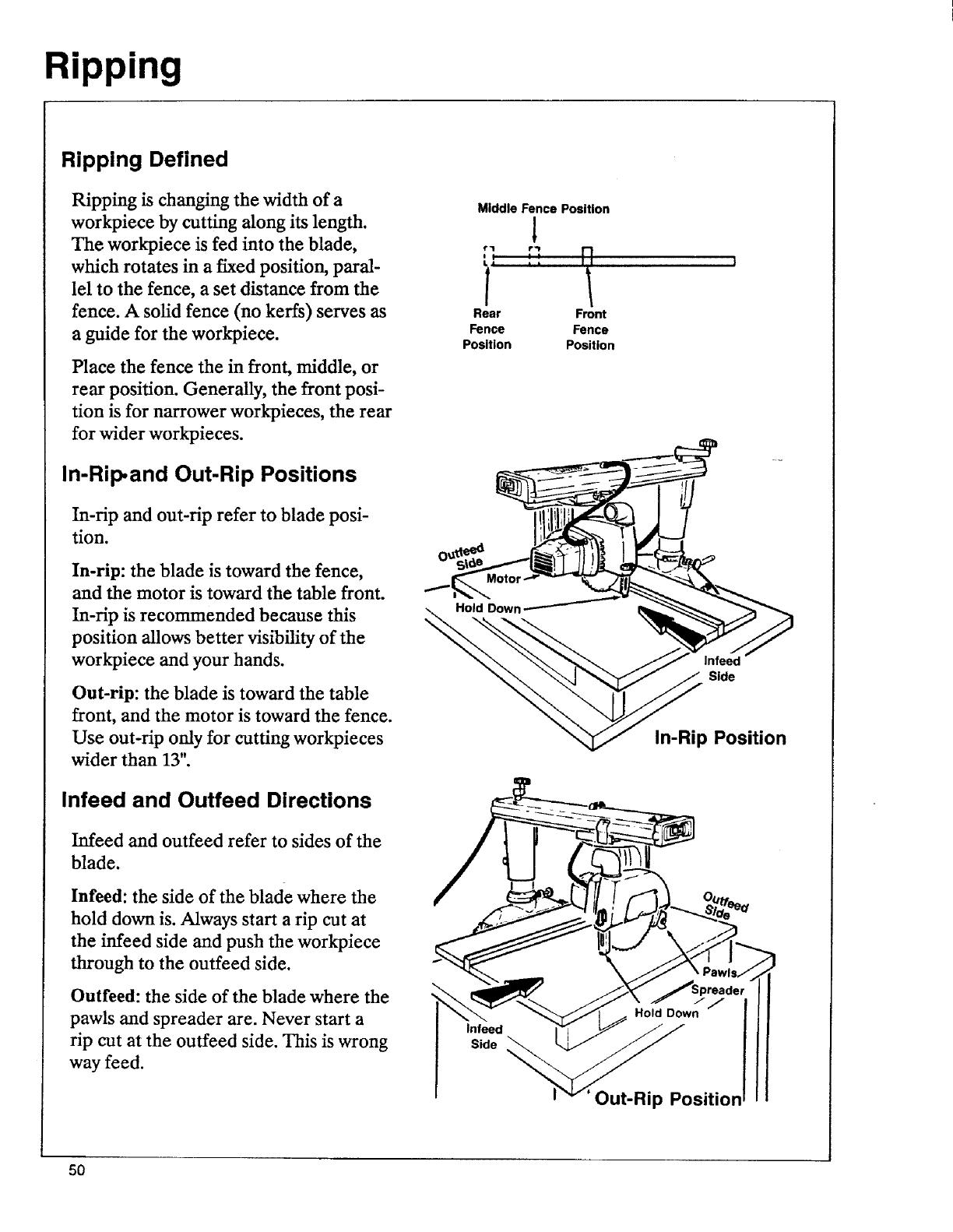
Ripping is changing the width of a
workpiece by cutting along its length.
The workpiece is fed into the blade,
which rotates in a fixed position, paral-
lel to the fence, a set distance from the
fence. A solid fence (no kerfs) serves as
a guide for the workpiece.
Place the fence the in front, middle, or
rear position. Generally, the front posi-
tion is for narrower work_ieces, the rear
for wider workpieces.
In-Rip, and Out-Rip Positions
In-rip and out-rip refer to blade posi-
tion.
In-rip: the blade is toward the fence,
and the motor is toward the table front.
In-rip is recommended because this
position allows better visibility of the
workpiece and your hands.
Out-rip: the blade is toward the table
front, and the motor is toward the fence.
Use out-rip only for cutting workpieces
wider than 13".
Infeed and Outfeed Directions
Infeed and outfeed refer to sides of the
blade.
Infeed: the side of the blade where the
hold down is. Always start a rip cut at
the infeed side and push the workpiece
through to the outfeed side.
Outfeed: the side of the blade where the
pawls and spreader are. Never start a
rip cut at the outfeed side. This is wrong
way feed.
Middle Fence Position
1
€'1 f'l 1
Ii&I I
Rear Front
Fence Fence
Position Position
Hold Down
Side
In-Rip Position
Infeed
Side
Out-Rip Position
50

Ripping
Workpiece Positioning
Always set up so that the widest part of
the workpiece is between the blade and
fence. For example, ffyou want to rip 1"
off a 10" wide workpiece, set the saw
blade 9" from the fence.
Widest Part
of Workplece
Push Sticks and Push Blocks
Push sticks and push blocks are used in-
stead of the hands to push the
workpiece through to complete the cuts.
A push block is used with an auxiliary
fence. See Cutting Aides.
Use a push stick when the space be-
tween the blade and fence is 2" or more.
2"or More
Push Stick
Use apush block and auxiliary fence
when the space between the blade and
fence is _ to 2".
Do not make rip cuts when space be-
tween blade and fence is narrower than
1,_#.
51
Ripping
Ripping Safety
The hazards associated with ripping are
outfeed zone hazard, kickback, wrong
way feed, and thrown chips. This section
explains these hazards and tells how to
avoid them or reduce the risk of their
happening. Read the ripping safety in-
formation and instructions before
making any type of rip cut. Follow these
steps every time you make a rip cut.
Outfeed Zone Hazard
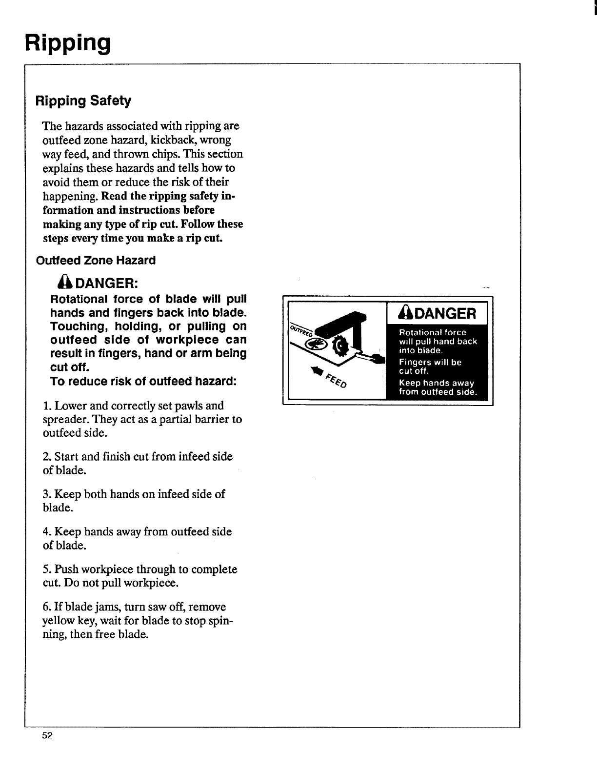
DANGER:
Rotational force of blade will pull
hands and fingers back into blade.
Touching, holding, or pulling on
outfeed side of workpiece can
result in fingers, hand or arm being
cut off.
To reduce risk of outfeed hazard:
1. Lower and correctly set pawls and
spreader. They act as a partial barrier to
outfeed side.
2. Start and finish cut from infeed side
of blade.
3. Keep both hands on infeed side of
blade.
4. Keep hands away from outfeed side
of blade.
5. Push workpiece through to complete
cut. Do not pull workpiece.
6. If blade jams, turn saw off, remove
yellow key, wait for blade to stop spin-
ning, then free blade.
DANGER
52
Ripping
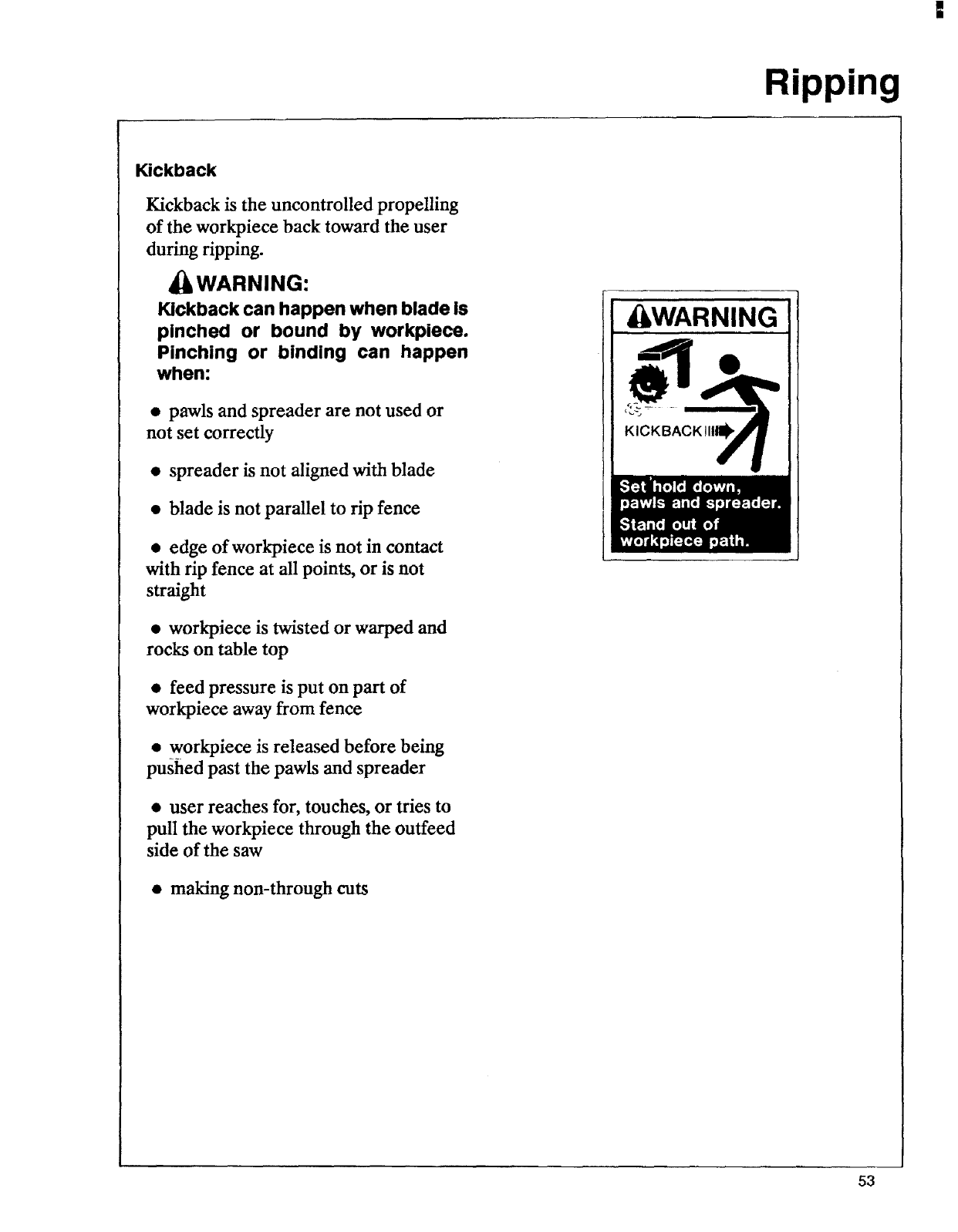
Kickback
Kickback is the uncontrolled propelling
of the workpiece back toward the user
during ripping.
_WARNING:
Kickback can happen when blade is
pinched or bound by workpiece.
Pinching or binding can happen
when:
•pawls and spreader are not used or
not set correctly
• spreader is not aligned with blade
• blade is not parallel to rip fence
• edge of workpiece is not in contact
with rip fence at all points, or is not
straight
• workpiece is twisted or warped and
rocks on table top
• feed pressure is put on part of
workpiece away from fence
• workpiece is released before being
pushed past the pawls and spreader
•user reaches for, touches, or tries to
pull the workpiece through the outfeed
side of the saw
• making non-through cuts
WARNING
53
Ripping
To reduce risk of kickback:
1. Correctly set pawls and spreader.
Spreader keeps workpiece from binding
or pinching blade; pawls grab into
workpiece to stop or slow kickback if
one happens.
2. Check that spreader is in line with
blade. See Alignment and Adjustment.
3. Cut only straight workpieees so sur-
face will lie flat on table and edge will
stay tight against fence. If you must cut
an irregular workpiece, attach a straight
edge. See Cutting Aides.
4. Apply feed pressure to part of
workpiece next to fence.
5. Push workpiece through from infeed
to outfeed side until it passes pawls and
spreader.
6. Keep hands away from outfeed side
of blade.
7. If blade jams, turn saw off, remove
yellow key, wait for blade to stop spin-
ning, then free blade.
8. When cutting composition materials,
put rough side up so pawls will grab.
9. Avoid cutting through very hard areas
like knots.
10. Use featherboard. See Cutting
Aides.
11. Stand out of workpiece path.
54
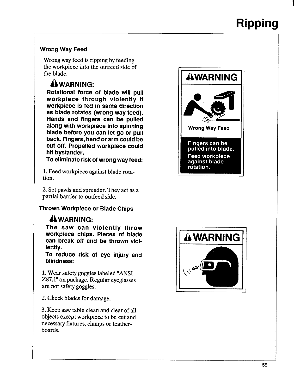
Wrong Way Feed
Wrong way feed is ripping by feeding
the workpiece into the outfeed side of
the blade.
_WARNING:
Rotational force of blade will pull
workpiece through violently if
workpiece is fed in same direction
as blade rotates (wrong way feed).
Hands and fingers can be pulled
along with workpiece into spinning
blade before you can let go or pull
back. Fingers, hand or arm could be
cut off. Propelled workplece could
hit bystander.
To eliminate risk of wrong way feed:
1. Feed workpiece against blade rota-
tion.
2. Set pawls and spreader. They act as a
partial barrier to outfeed side.
Thrown Workpiece or Blade Chips
_WARNING:
The saw can violently throw
workpiece chips. Pieces of blade
can break off and be thrown viol-
lently.
To reduce risk of eye injury and
blindness:
1. Wear safety goggles labeled "ANSI
Z87.1" on package. Regular eyeglasses
are not safety goggles.
2. Check blades for damage.
3. Keep saw table clean and clear of all
objects except workpiece to be cut and
necessary fixtures, damps or feather-
boards.
Ripping
&WARNING
Wrong Way Feed
& WARNING
55
Ripping
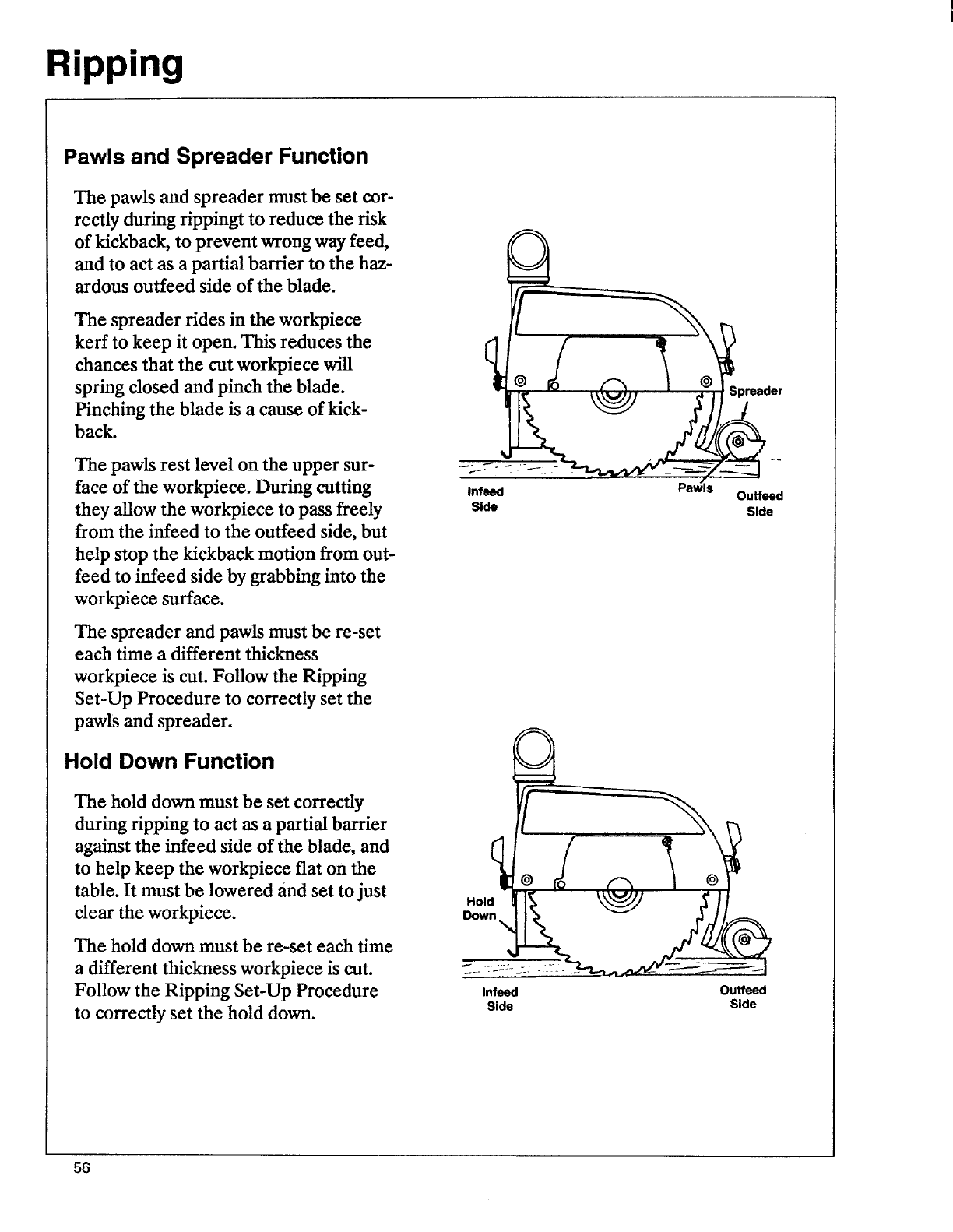
Pawls and Spreader Function
The pawls and spreader must be set cor-
rectly during tippingt to reduce the risk
of kickback, to prevent wrong way feed,
and to act as a partial barrier to the haz-
ardous ouffeed side of the blade.
The spreader tides in the workpiece
kerr to keep it open. This reduces the
chances that the cut workpiece will
spring dosed and pinch the blade.
Pinching the blade is a cause of kick-
back.
The pawls rest level on the upper sur-
face of the workpiece. During cutting
they allow the workpiece to pass freely
from the infeed to the outfeed side, but
help stop the kickback motion from out-
feed to infeed side by grabbing into the
workpiece surface.
The spreader and pawls must be re-set
each time a different thickness
workpiece is cut. Follow the Ripping
Set-Up Procedure to correctly set the
pawls and spreader.
Hold Down Function
The hold down must be set correctly
during tipping to act as a partial barrier
against the infeed side of the blade, and
to help keep the workpiece flat on the
table. It must be lowered and set to just
clear the workpiece.
The hold down must be re-set each time
a different thickness workpiece is cut.
Follow the Ripping Set-Up Procedure
to correctly set the hold down.
•er
Infeed Paw_s Outfeed
Side Side
Hold
Infeed Outfeed
Side Side
56
Ripping
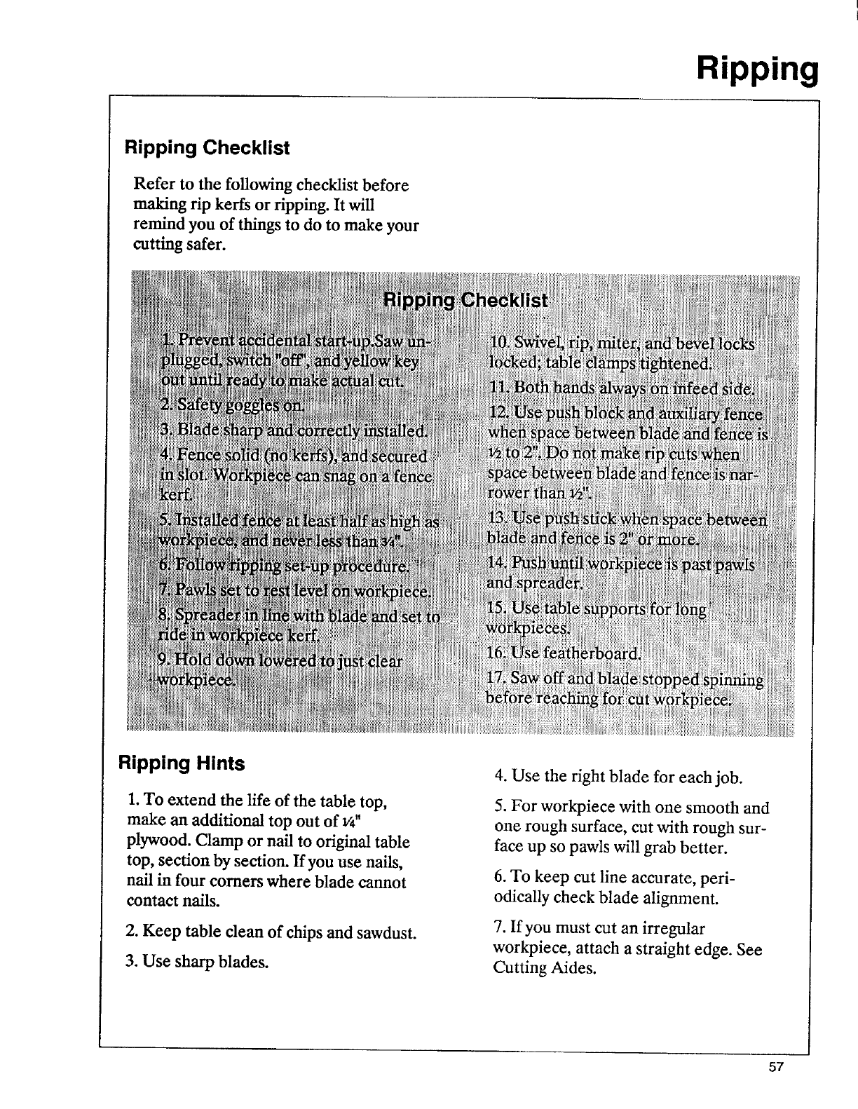
Ripping Checklist
Refer to the following checklist before
making rip kerfs or ripping. It will
remind you of things to do to make your
cutting safer.
Ripping Hints
1. To extend the life of the table top,
make an additional top out of v4"
plywood. Clamp or nail to original table
top, section by section. If you use nails,
nail in four comers where blade cannot
contact nails.
2. Keep table clean of chips and sawdust.
3. Use sharp blades.
4. Use the right blade for each job.
5. For workpiece with one smooth and
one rough surface, cut with rough sur-
face up so pawls will grab better.
6. To keep cut line accurate, peri-
odically check blade alignment.
7. If you must cut an irregular
workpiece, attach a straight edge. See
Cutting Aides.
57
Ripping
Kerfs
A kerr or shallow cut is needed in the
table to serve as a path for the blade
and to ensure that the blade cuts all the
way through the workpiece. A kerf is
needed for each different cutting posi-
tion.
Follow these steps to make a kerr:
1. Check that saw is unplugged, switch is
"off', and yellow key is out.
2. Put solid (no kerfs) fence in desired
position and tighten table damps.
3. Index arm to 0°miter position. Lock
miter lock.
4. Set desired bevel angle and lock
bevel lock.
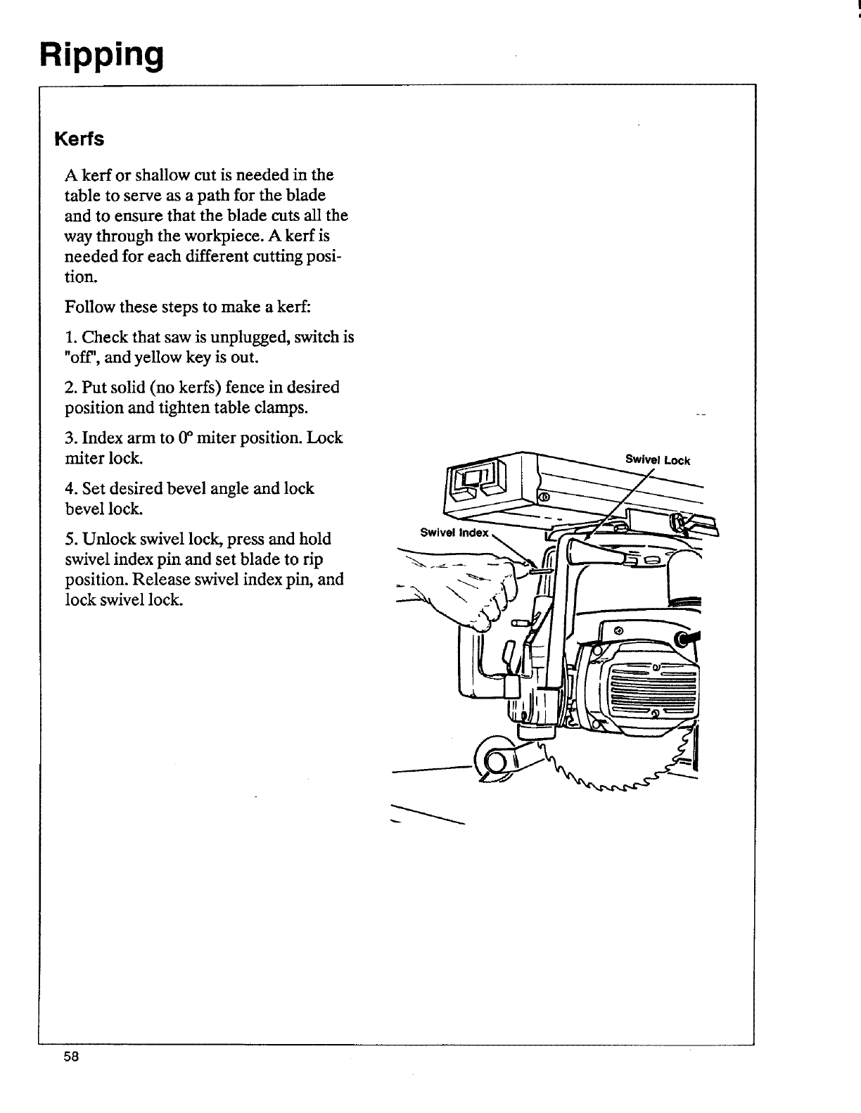
5. Unlock swivel lock, press and hold
swivel index pin and set blade to rip
position. Release swivel index pin, and
lock swivel lock.
Swivel Lock
58
Ripping
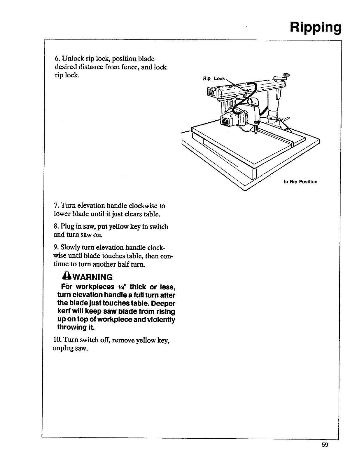
6. Unlock rip lock, position blade
desired distance from fence, and lock
rip lock.
I
Rip
In-Rip Position
7. Turn elevation handle clockwise to
lower blade until it just clears table.
8. Plug in saw, put yellow key in switch
and turn saw on.
9. Slowly turn elevation handle clock-
wise until blade touches table, then con-
tinue to turn another half turn.
_WARNING
For workpieces v4" thick or less,
turn elevation handle a full turn after
the blade just touches table. Deeper
kerf will keep saw blade from rising
up on top of workplece and violently
throwing It.
10. Turn switch off, remove yellow key,
unplug saw.
59
Ripping
Ripping Set-up Procedure
Follow these steps before ripping. These
steps must be repeated each time a dif-
ferent thickness workpiece is ripped.
1. Check that saw is unplugged, switch is
"oft", and yellow key is out.
2. Put solid (no kerfs) fence in desired
position and tighten table clamps. (In-
sert amdliary fence if space between
blade and fence will be _ to 2".)
3. Index arm to 0° miter position and
lock miter lock. Set desired bevel angle
and lock bevel lock.
4. Unlock swivel lock, press and hold
swivel index pin, and set blade to in-rip
position. Lock swivel lock. (Set to out-
rip position only if overall workpiece is
wider than 13".)
5. Unlock rip lock, set blade desired dis-
tance from fence, lock rip lock. Always
set blade so wider part ofworkplece will
be between blade and fence.
6. Ready push stick if space between
blade and fence is 2" or more. Ready
push block if using auxiliary fence.
7. Lower blade into kerf, but not touch-
ing kerf bottom. Blade should move
freely. If there is no kerf, make one fol-
lowing instructions for kerfs.
8. Place workpiece on saw table, paral-
lel to and up against blade.
9. Unlock and set hold down to just
clear workpiece surface, then lock.
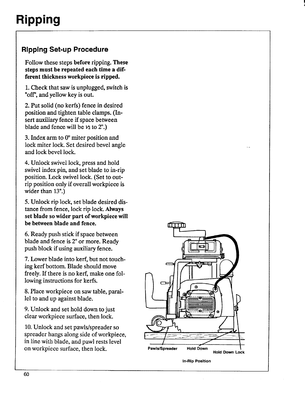
10. Unlock and set pawls/spreader so
spreader hangs along side of workpiece,
in line with blade, and pawl rests level
on workpiece surface, then lock. f,
Pawls/Spreader Hold Down
In-Rip Position
Hold Down Lock
6O
Ripping
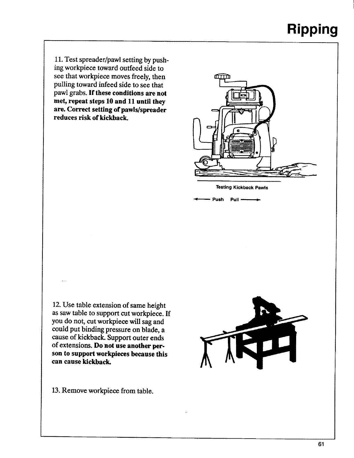
11. Test spreader/pawl setting by push-
ing workpiece toward ouffeed side to
see that workpiece moves freely, then
pulling toward infeed side to see that
pawl grabs. If these conditions are not
met, repeat steps 10 and 11 until they
are. Correct setting of pawls/spreader
reduces risk of kickback.
Testing Kickback Pawls
Push Pull
12. Use table extension of same height
as saw table to support cut work_iece. If
you do not, cut workpieee will sag and
could put binding pressure on blade, a
cause of kickback. Support outer ends
of extensions. Do not use another per-
son to support workpieees because this
can cause kickback.
13. Remove workpiece from table.
61
Ripping
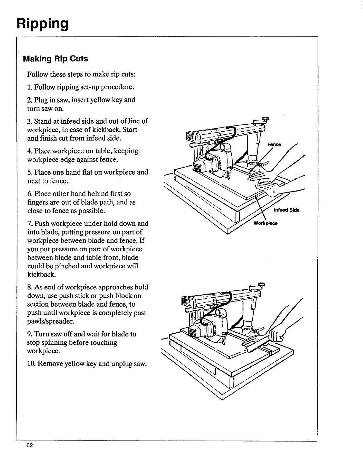
Making Rip Cuts
Follow these steps to make rip cuts:
1. Follow ripping set-up procedure.
2. Plug in saw, insert yellow key and
turn saw on.
3. Stand at infeed side and out of line of
workpiece, in case of kickback. Start
and finish cut from infeed side.
4. Place workpiece on table, keeping
workpiece edge against fence.
5. Place one hand flat on workpiece and
next to fence.
6. Place other hand behind first so
fingers are out of blade path, and as
close to fence as possible.
7. Push workpiece under hold down and
into blade, putting pressure on part of
workpiece between blade and fence. If
you put pressure on part of workpiece
between blade and table front, blade
could be pinched and workpiece will
kickback.
8. As end of workpiece approaches hold
down, use push stick or push block on
section between blade and fence, to
push until workpiece is completely past
pawls/spreader.
9. Turn saw off and wait for blade to
stop spinning before touching
workpiece.
10. Remove yellow key and unplug saw.
f
Infeed Side
Workplece
62
Cutting Aides
Cutting aides include fences, push
sticks, auxiliary fences, push blocks,
featherboards, and straight edges.
Fences
Fences are required for all saw opera-
tions.
Crosscutting requires fences with kerfs
(slots) to match the path of the saw, be-
cause the saw blade is pulled through
the kerf in the fence to cut the
workpiece.
Ripping requires a solid fence with no
kerfs or slots, because the fence serves
as a guide for the workpiece being
pushed into the saw blade.
&WARNING
If workpiece is pushed along fence
witll kerfs, workpiece can get
caught on kerr, pinch blade and
cause kickback. Do not use
crosscutting fence for ripping.
It is a good idea to have more than one
crosscutting fence on hand, because if
you-tase the same fence for too many
kerfs, the fence will weaken. Depending
on the angle, bevel kerfs can be very
broad, and may overlap other kerfs.
To make a fence:
1.Use a/4"knot free lumber cut to 30".
Do not use particle board or other com-
posite materials because they are not
strong enough. Note: Installed fence
must be at least half as high as the
workpiece, and never less than Y4".The
fence can be as high or higher than the
workpiece.
63
Cutting Aides
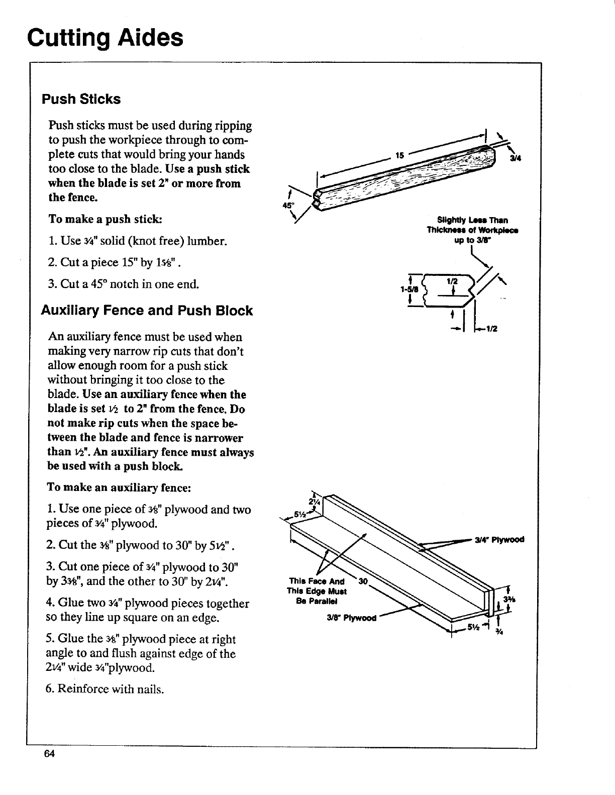
Push Sticks
Push sticks must be used during ripping
to push the workpiece through to com-
plete cuts that would bring your hands
too close to the blade. Use a push stick
when the blade is set 2"or more from
the fence.
To make a push stick:
1. Use a/4"solid (knot free) lumber.
2. Cut a piece 15" by 1_".
3. Cut a 45° notch in one end.
Auxiliary Fence and Push Block
An auxiliary fence must be used when
making very narrow rip cuts that don't
allow enough room for a push stick
without bringing it too close to the
blade. Use an auxiliary fence when the
blade is set _to 2" from the fence. Do
not make rip cuts when the space be-
tween the blade and fence is narrower
than 1/2".An auxiliary fence must always
be used with a push block.
To make an auxiliary fence:
1. Use one piece of Ys"plywood and two
pieces of 3/4"plywood.
2. Cut the _" plywood to 30" by 5_".
3. Cut one piece of _'4"plywood to 30"
by 3a_",and the other to 30" by 2v4".
4. Glue two _/4"plywood pieces together
so they line up square on an edge.
5. Glue the 3_" plywood piece at right
angle to and flush against edge of the
21/4"wide _'4"plywood.
6. Reinforce with nails.
This Face And
This Edge Mull
Be Parallel
3/8"
lS 3/4
Slightly Loss Than
Thicknessof_
up to 3/8"
-ILo
3,'4"Plywood
64
Cutting Aides
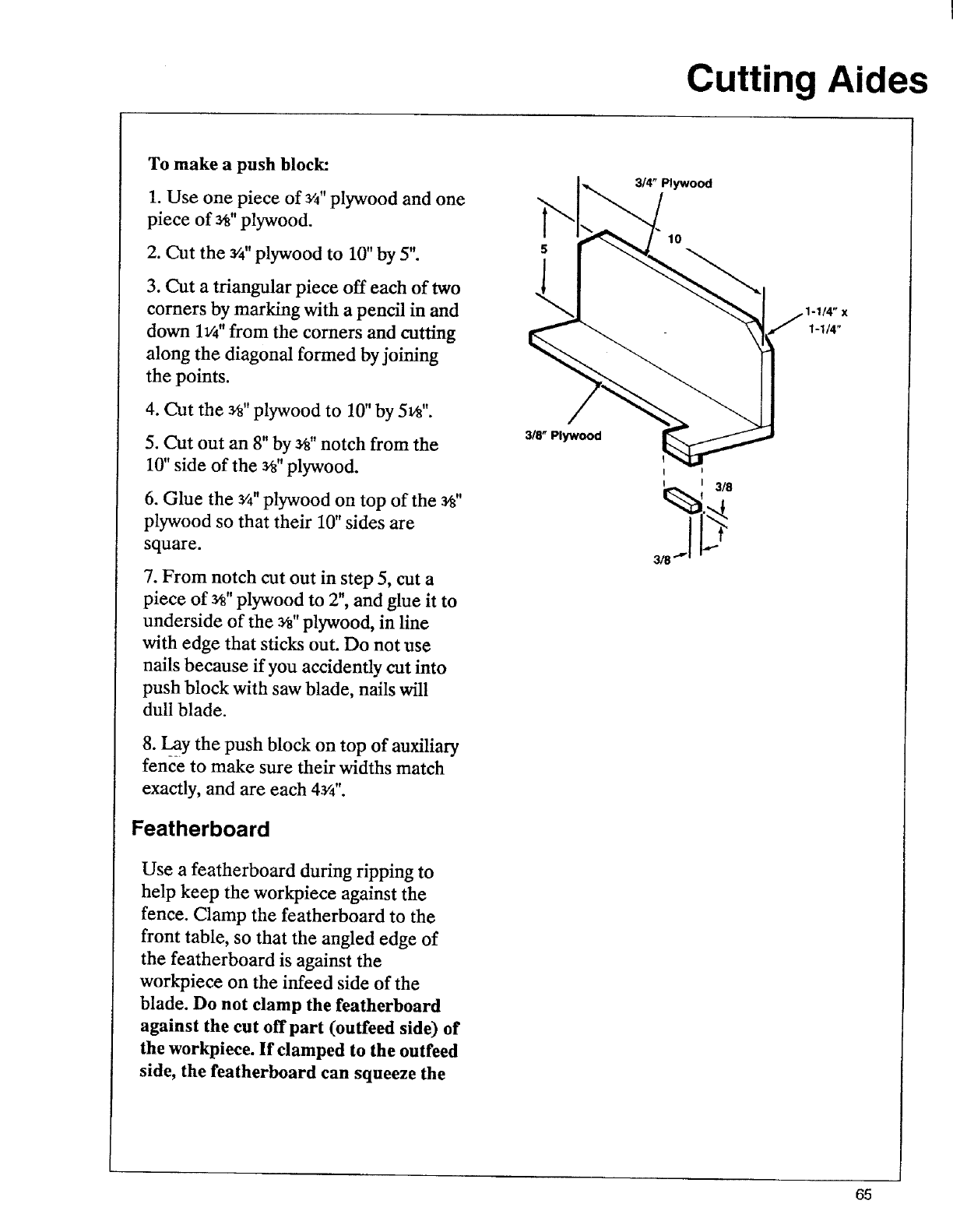
To make a push block:
1. Use one piece of _/4"plywood and one
piece of _" plywood.
2. Cut the a/4"plywood to 10" by 5".
3. Cut a triangular piece off each of two
corners by marking with a pencil in and
down 1v4"from the corners and cutting
along the diagonal formed by joining
the points.
4. Cut the _" plywood to 10"by 5v8".
5. CUt out an 8" by _" notch from the
10" side of the a_"plywood.
6. Glue the 3/4"plywood on top of the _"
plywood so that their 10" sides are
square.
7. From notch cut out in step 5, cut a
piece of 3_"plywood to 2", and glue it to
underside of the Y8"plywood, in line
with edge that sticks out. Do not use
nails because if you accidently cut into
push block with saw blade, nails will
dull blade.
8. _l__aythe push block on top of auxiliary
fence to make sure their widths match
exactly, and are each 43/4''.
Featherboard
Use a featherboard during ripping to
help keep the workpiece against the
fence. Clamp the featherboard to the
front table, so that the angled edge of
the featherboard is against the
workpiece on the infeed side of the
blade. Do not clamp the featherboard
against the cut off part (outfeed side) of
the workpiece. If clamped to the outfeed
side, the featherboard can squeeze the
3/8" Plywood
314" Plywood
10
I I
318"" _
1-1/4"
65
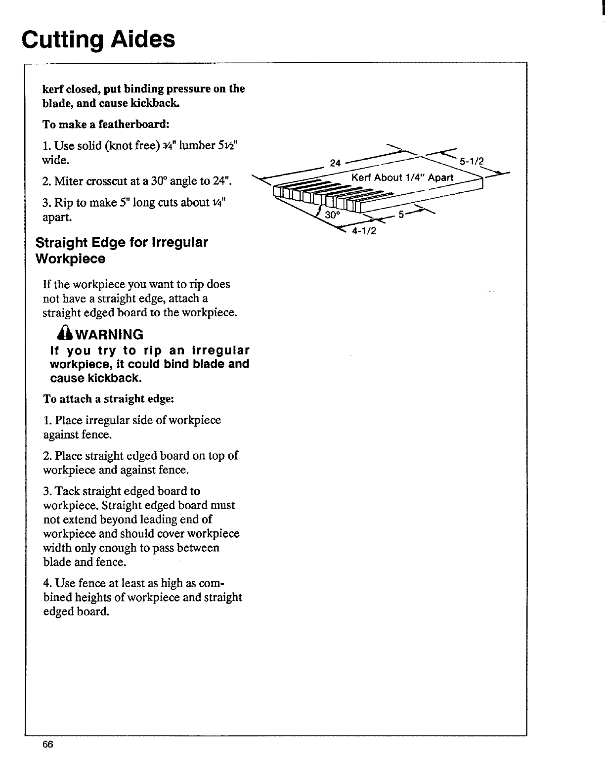
Cutting Aides
kerf closed, put binding pressure on the
blade, and cause kickback.
To make a featherboard:
1. Use solid (knot free) 3/4"lumber 5_"
wide.
2. Miter crosscut at a 30 °angle to 24".
3. Rip to make 5" long cuts about v'4"
apart.
Straight Edge for Irregular
Workpiece
If the workpiece you want to rip does
not have a straight edge, attach a
straight edged board to the workpiece.
_WARNING
If you try to rip an Irregular
workpiece, it could bind blade and
cause kickback.
To attach a straight edge:
1. Place irregular side of workpiece
against fence.
2. Place straight edged board on top of
workpiece and against fence.
3. Tack straight edged board to
workpiece. Straight edged board must
not extend beyond leading end of
workpiece and should cover workpiece
width only enough to pass between
blade and fence.
4. Use fence at least as high as com-
bined heights of workpiece and straight
edged board.
24 -1/2
66
Accessories
Accessories Safety
1. Use only accessories listed in this sec-
tion. Use of any other accessory or at-
tachment might increase the risk of
injury to you or others.
2. Follow accessory manufacturer's in-
structions on proper and intended use.
3. Use of grinding wheels, abrasive or
cut offwheels, or wire wheels is
dangerous because they can break ex-
plosively and throw pieces. You can be
blinded or receive a life threatening
puncture wound. Do not use grinding
wheels, abrasive/cut off wheels or wire
wheels.
Lower Blade Guard
The following safety information and in-
structions apply to all blades and acces-
sories.
The lower blade guard is required by
the Occupational Safety and Health Ad-
ministration (OSHA) if the radial saw is
used-commercially. The lower blade
guard is intended for use only in repeti-
tive 90°crosscutting.
Repetitive 90 ° crosscutting is the
repeated and continuous cutting of
many pieces of lumber to the same
length with the saw placed in the 90 °
crosscut position.
In repetitive 90°crosscutting, the guard
may reduce the chance of accidentally
touching the blade from the side. This
protection is possible ONLY when:
•the blade is in its rearmost position
and
•the guard is resting on the table so
the leading and trailing teeth of the
blade are not exposed from the sides.
The lower guard ONLY provides
protection against minor lacerations
and bruises that occur from contact with
the flat sides of the spinning blade.
_WARNING:
Lower blade guard will not provide
any protection if blade is pulled over
your hand, or your hand enters
blade path from front or rear of
blade. Fingers or hand can be cut
or cut off.
_WARNING:
Remove lower blade guard for ALL
other types of cuts except repetitive
90* crosscutting. Using lower guard
other than for repetitive 90 °
crosscutting will increase risk of
certain hazards:
•During rip and bevel cuts, the
workpiece or narrow cut-off pieces can
be pinched between the guard and the
blade. Workpiece or cut-off pieces can
kickback.
•In the bevel position the blade teeth
are fully exposed. Fingers or hand can
be cut off.
• Cut off pieces can jam between the
guard and blade. Turn saw off and wait
for blade to stop before freeing a
jammed guard or blade.
67
Accessories
• Workpiece or cut-off pieces can be
violently thrown by the blade. Wear
safety goggles
CAUTION:
Lower blade guard can get caught
or jam In fence or table kerfs.
Read and follow the warning on the
lower outer guard:
WARNING:
To avoid injury shut off
power before clearing a
jammed lower guard
Accessories for this Saw
These accessories are designed to fit
this saw. Read and follow instructions
that come with accessory.
Item ........................................ Catalog No.
Saw blades (81/4"diameter with _"
hole) ......................................... See Catalog
Taper Jig .......................................... 9-3233
Dado Set ........................................ 9-32581
Leg Set ............................................ 9-22244
BooRs
Power Tool Know How Handbook ........
.................................................. See Catalog
Guards
Lower Retractable Guard* For 90 °
Repetitive Crosscut Only ............ 9-23473
*See the information and instructions
about the lower retractable guard in this
section.
68
Maintenance
WARNING:
To avoid shock, burns, or lacera-
tions from accidental start up of
saw, turn power switch off and un-
plug saw before doing maintenance
or servicing saw.
General Information
When new, the saw requires no lubrica-
tion. The saw has been partially aligned
and all bearings are lubricated and
sealed for life. Ill time, in order to keep
the saw in good working order, it will be
necessary to clean, lubricate and realign.
Replacing Pawls
Make sure the teeth of the antikickback
pawls are always sharp. If they become
dull they must be replaced. To replace:
1.Use v2" wrench or socket to remove
5/lg' hex nut and old pawls.
2. Assemble new antikickback pawls
and spreader to bar.
3. Align spreader to blade according to
instructions in Alignment and Adjust-
ment.
Cleaning
Periodically remove any heavy build-up
of sawdust that may accumulate on the
saw. The absorbing tendency of sawdust
will draw lubricants away from the areas
where they are needed. Wipe the car-
riage bearings and track surfaces with a
dry or lightly oiled cloth.
To avoid motor damage due to sawdust
build-up, which interferes with normal
motor ventilation, blow out or vacuum
the motor often.
Lubrication
Do not lubricate motor bearings. Motor
bearings are sealed and do not need
added lubrication.
You can lubricate other points if neces-
sary, but only when sticking or binding
occurs.
Adjustments for Wear
Bevel Lock
The bevel lock needs adjustment if the
motor can be moved by hand when the
bevel lock is locked. To make adjust-
ment:
1. Use v8"hex wrench to loosen screw
under right comer (pivot point) of bevel
lock just enough to allow bevel lock
lever to drop down. (See figure 2,
Repair Parts.)
2. Use bevel lock lever as wrench to in-
crease locking characteristics.
3. Test lock for desired locked/unlocked
condition. Repeat step 2 if necessary.
4. Tighten screw.
Swivel Lock
The swivel lock is a friction lock that
prevents play between the yoke and car-
riage (#41 and #12, figure 2, Repair
Parts). It needs adjustment if the lock
handle has to be moved more than 90°
to lock. To make adjustment:
1. Use 1s/if' wrench to tighten nut (#1,
figure 2, Repair Parts).
2. Test lock, and repeat step 1 as needed.
69
Maintenance
Carriage Bearings
The carriage should roll freely but with
some resistance for the entire length of
travel. If the carriage moves too freely
or with too much resistance, the bear-
ings need adjustment. To adjust, follow
the instructions under Carriage Bear-
ings in Alignment and Adjustment.
Miter Lock
If the radial arm can be moved by hand
when the miter lock is locked in an unin-
dexed position, the lock needs adjust-
ment. To adjust, follow the instructions
under Miter Lock Assembly.
Rip Lock
If the carriage can be moved by pushing
and pulling on the saw handle when the
rip lock is locked, the lock needs adjust-
ment. To adjust:
1. Lock rip lock. Use screwdriver to
pop out "e" ring.
2. Remove rip lock handle and use as
wrench to tighten nut.
3. Test for desired locked/unlocked con-
dition. Repeat step 2 of necessary.
4. Re-insert "e" ring.
Hold Down and Pawls/Spreader
Locks
If the hold down or the pawl/spreader
do not hold when locked, or if the lock
lever has to be turned more than 90°to
lock, the lock needs adjustment. To
make adjustment:
1. Lock hold down or pawls/spreader
lock. Use screwdriver to pop out "e" ring.
2. Remove lock handle and re-position
at 90°.
3. Re-insert "e" ring.
4. Check that hold down or
pawls/spreader move freely when lock is
unlocked.
Motor
To avoid motor damage due to sawdust
buildup, which interferes with normal
motor ventilation, blow out or vacuum
the motor often.
70
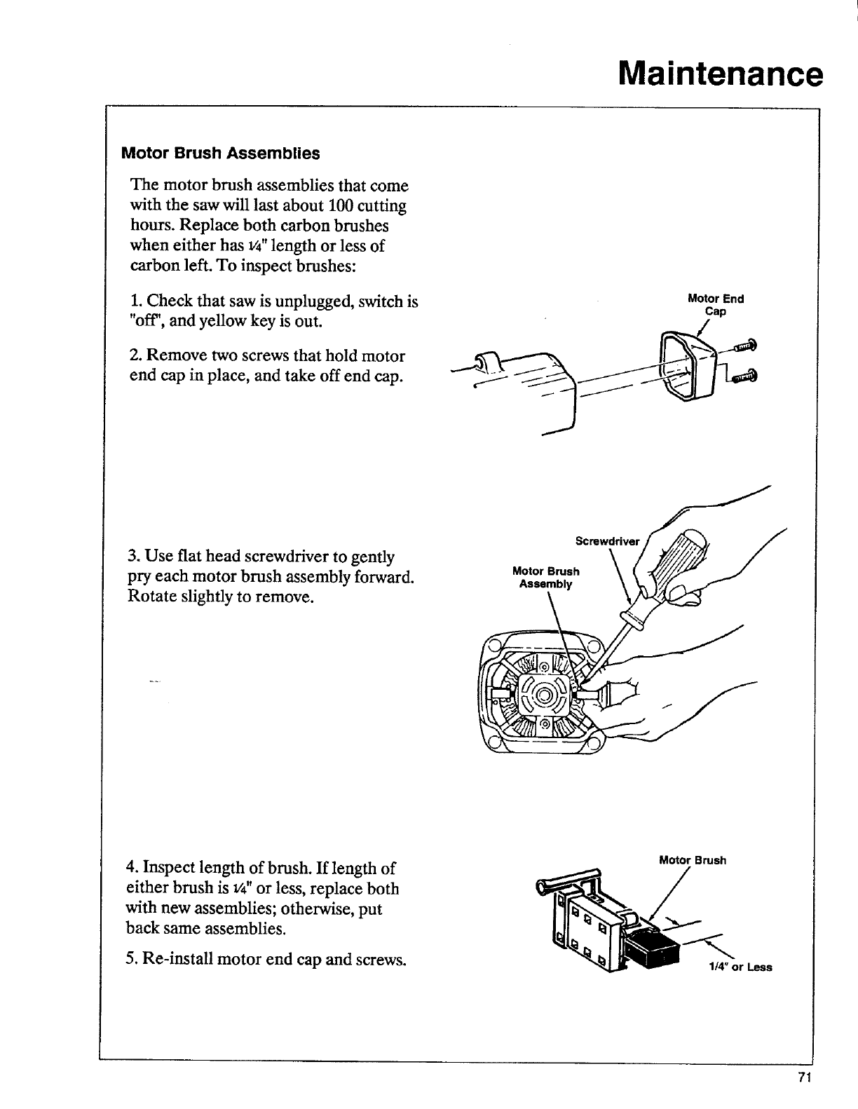
Maintenance
Motor Brush Assemblies
The motor brush assemblies that come
with the saw will last about 100 cutting
hours. Replace both carbon brushes
when either has W' length or less of
carbon left. To inspect brushes:
1. Check that saw is unplugged, switch is
"off", and yellow key is out.
2. Remove two screws that hold motor
end cap in place, and take off end cap.
Motor End
Cap
3. Use flat head screwdriver to gently
pry each motor brush assembly forward.
Rotate slightly to remove.
Screwdriver ___ _
Motor Brush _ _ -_'////_./J_"
Assembly
4. Inspect length of brush. If length of
either brush is W' or less, replace both
with new assemblies; otherwise, put
back same assemblies.
5. Re-install motor end cap and screws.
Motor Brush
1/4" or Less
71
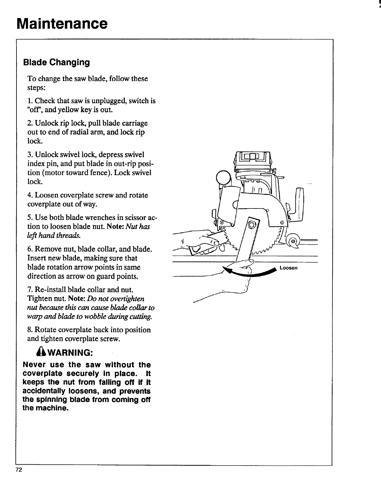
Maintenance
Blade Changing
To change the saw blade, follow these
steps:
1. Check that saw is unplugged, switch is
"oft", and yellow key is out.
2. Unlock rip lock, pull blade carriage
out to end of radial arm, and lock rip
lock.
3. Unlock swivel lock, depress swivel
index pin, and put blade in out-rip posi-
tion (motor toward fence). Lock swivel
lock.
4. Loosen coverplate screw and rotate
coverplate out of way.
5. Use both blade wrenches in scissor ac-
tion to loosen blade nut. Note: Nut has
left hand threads.
6. Remove nut, blade collar, and blade.
Insert new blade, making sure that
blade rotation arrow points in same
direction as arrow on guard points.
7. Re-install blade collar and nut.
Tighten nut. Note: Do not overtighten
nut because this can cause blade collar to
warp and blade to wobble during cutting.
8. Rotate coverplate back into position
and tighten coverplate screw.
I WARNING:
Never use the saw without the
coverplate securely in place. It
keeps the nut from falling off if it
accidentally loosens, and prevents
the spinning blade from coming off
the machine.
sen
J
72
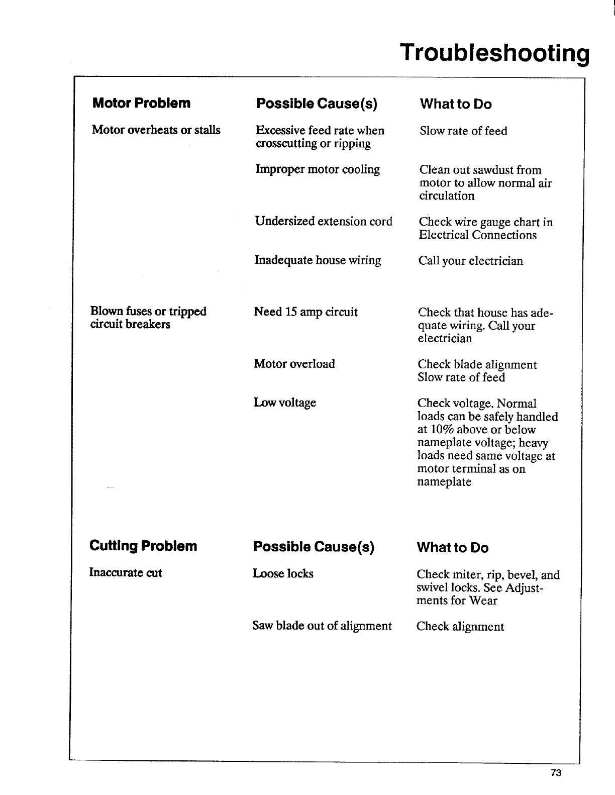
Troubleshooting
Motor Problem
Motor overheats or stalls
Possible Cause(s)
Excessive feed rate when
crosscutting or ripping
Improper motor cooling
Undersized extension cord
Inadequate house wiring
What to Do
Slow rate of feed
Clean out sawdust from
motor to allow normal air
circulation
Check wire gauge chart in
Electrical Connections
Call your electrician
Blown fuses or tripped
circuit breakers Need 15 amp circuit
Motor overload
Low voltage
Check that house has ade-
quate wiring. Call your
electrician
Check blade alignment
Slow rate of feed
Check voltage. Normal
loads can be safely handled
at 10% above or below
nameplate voltage; heax2€
loads need same voltage at
motor terminal as on
nameplate
Cutting Problem
Inaccurate cut
Possible Cause(s)
Loose locks
Saw blade out of alignment
What to Do
Check miter, rip, bevel, and
swivel locks. See Adjust-
ments for Wear
Check alignment
73
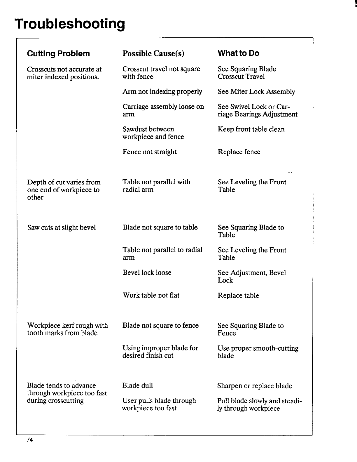
Troubleshooting
Cutting Problem
Crosscuts not accurate at
miter indexed positions.
Possible Cause(s)
Crosscut travel not square
with fence
Arm not indexing properly
Carriage assembly loose on
anti
Sawdust between
work_iece and fence
Fence not straight
What to Do
See Squaring Blade
Crosscut Travel
See Miter Lock Assembly
See Swivel Lock or Car-
riage Bearings Adjustment
Keep front table clean
Replace fence
Depth of cut varies from
one end of workpiece to
other
Table not parallel with
radial arm See Leveling the Front
Table
Saw cuts at slight bevel Blade not square to table
Table not parallel to radial
arln
Bevel lock loose
Work table not flat
See Squaring Blade to
Table
See Leveling the Front
Table
See Adjustment, Bevel
Lock
Replace table
Workpiece kerf rough with
tooth marks from blade Blade not square to fence
Using improper blade for
desired finish cut
See Squaring Blade to
Fence
Use proper smooth-cutting
blade
Blade tends to advance
through workpiece too fast
during crosscutting
Blade dull
User pulls blade through
workpiece too fast
Sharpen or replace blade
Pull blade slowly and steadi-
ly through workpiece
74
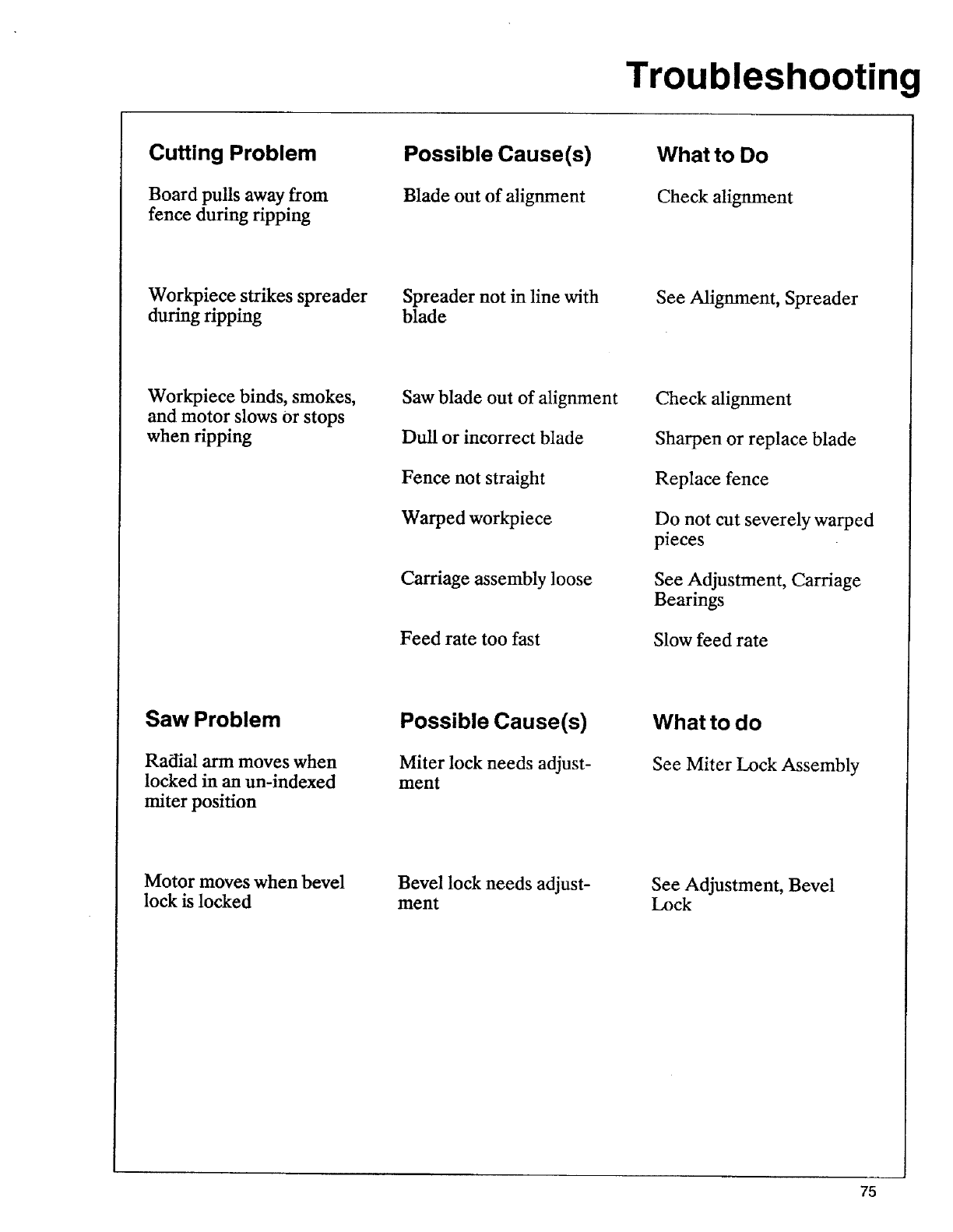
Troubleshooting
Cutting Problem
Board pulls away from
fence during ripping
Possible Cause(s)
Blade out of alignment
What to Do
Check alignment
Workpiece strikes spreader
during ripping Spreader not in line with
blade See Alignment, Spreader
Workpiece binds, smokes,
and motor slows Orstops
when ripping
Saw blade out of alignment
Dull or incorrect blade
Fence not straight
Warped workpiece
Carriage assembly loose
Feed rate too fast
Check alignment
Sharpen or replace blade
Replace fence
Do not cut severely warped
pieces
See Adjustment, Carriage
Bearings
Slow feed rate
Saw Problem
Radial arm moves when
locked in an un-indexed
miter position
Possible Cause(s)
Miter lock needs adjust-
ment
What to do
See Miter Lock Assembly
Motor moves when bevel
lock is locked Bevel lock needs adjust-
ment See Adjustment, Bevel
Lock
75
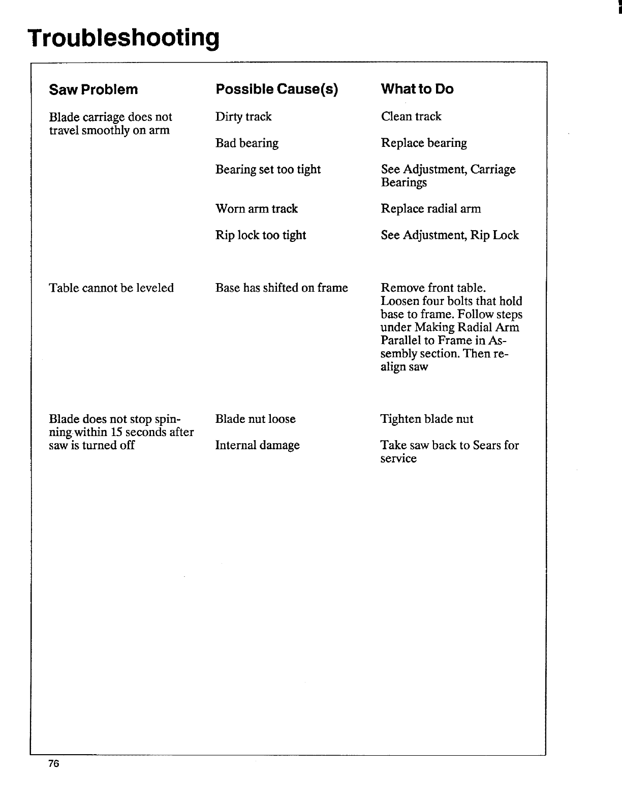
Troubleshooting
Saw Problem
Blade carriage does not
travel smoothly on arm
Possible Cause(s)
Dirty track
Bad bearing
Bearing set too tight
Worn arm track
Rip lock too tight
What to Do
Clean track
Replace bearing
See Adjustment, Carriage
Bearings
Replace radial arm
See Adjustment, Rip Lock
Table cannot be leveled Base has shifted on frame Remove front table.
Loosen four bolts that hold
base to frame. Follow steps
under Making Radial Arm
Parallel to Frame in As-
sembly section. Then re-
align saw
Blade does not stop spin-
ningwithin 15 seconds after
saw is turned off
Blade nut loose
Internal damage
Tighten blade nut
Take saw back to Sears for
service
76

Note: This page intentionally left blank. I
77
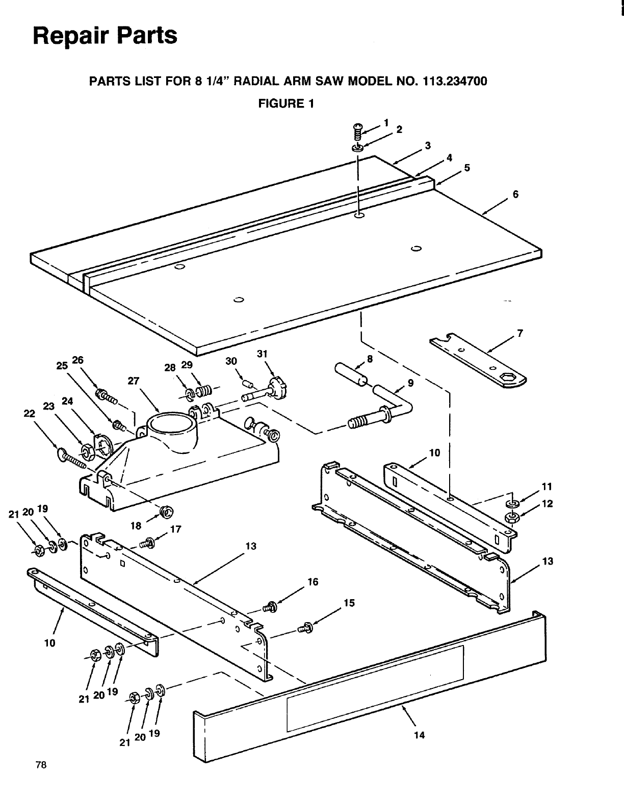
Repair Parts
PARTS LIST FOR 8 1/4" RADIAL ARM SAW MODEL NO. 113.234700
FIGURE 1
26
25\
23 24
22\
27
I
28 29 30 _j8_
,ol
J
21 20 19
13
15
13
10
14
78
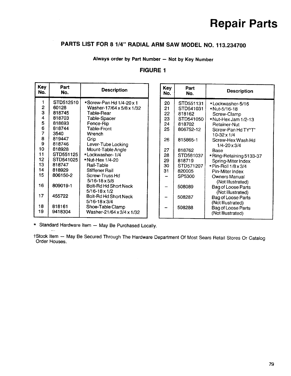
Repair Parts
PARTS LIST FOR 8 1/4" RADIAL ARM SAW MODEL NO. 113.234700
Always order by Part Number -- Not by Key Number
FIGURE 1
Key Part Description
No. No.
1STD512510
2 60128
3 818745
4818703
5818693
6818744
7 3540
8 819447
9 818746
10 818928
11 STD551125
12 STD541025
13 818747
14 818929
15 806150-2
16 809019-1
17 455722
18 818161
19 9418304
*Screw-Pan Hd 1/4-20 x 1
Washer-17/64 x 5/8 x 1/32
Table-Rear
Table-Spacer
Fence-Rip
Table-Front
Wrench
Grip
Lever-Tube Locking
Mount-Table Angle
* Lockwasher- 1/4
*Nut-Hex 1/4-20
Rail-Table
Stiffener Rail
Screw-Truss Hd
5/16-18 x 5/8
Bolt-Rd Hd Short Neck
5/16-18 x 1/2
Bolt-Rd Hd Short Neck
5/16-18 x 3/4
Shoe-Table Clamp
Washer-21/64 x 3/4 x 1/32
Key Part Description
No. No.
20 STD551131
21 STD541031
22 818162
23 STD541050
24 818702
25 806752-12
26 815865-1
27 818762
28 STD581037
29 818719
30 STD571207
31 820005
-SP5300
508089
508287
508288
*Lockwasher-5/16
*Nut-5/16-18
Screw-Clamp
*Nut-Hex Jam 1/2-13
Retainer-Nut
Screw-Pan Hd TY"T"
10-32x !/4
Screw-Hex Wash Hd
1/4-20x3/4
Base
*Ring-Retaining 5133-37
Spring-Miter Index
*Pin-Roll 1/8 x 3/4
Pin-Miter Index
Owners Manual
(Not Illustrated)
Bag of Loose Parts
(Not Illustrated)
Bag of Loose Parts
(Not Illustrated)
Bag of Loose Parts
(Not Illustrated)
*Standard Hardware Item -- May Be Purchased Locally.
%Stock Item -- May Be Secured Through The Hardware Department Of Most Sears Retail Stores Or Catalog
Order Houses.
79
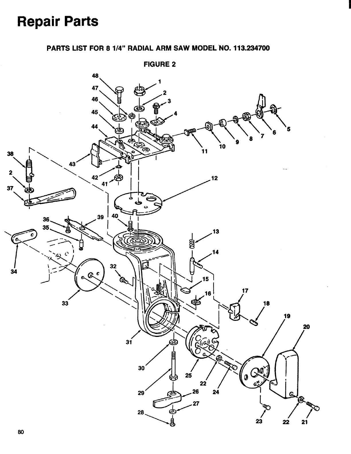
Repair Parts
PARTS LIST FOR 8 1/4" RADIAL ARM SAW MODELNO. 113.234700
FIGURE 2
45 \
44 \
11 10
34
8 7
9
/
31
19
2O
8O
24
23 21

Repair Parts
PARTS LIST FOR 8 1/4" RADIAL ARM SAW MODEL NO. 113.234700
Always order by Part Number -- Not by Key Number
FIGURE 2
Key Part Description
No. No.
1
2
3
4
5
6
7
8
9
10
11
12
13
14
15
16
17
18
19
20
21
22
23
24
25
STD541462
60047
815865
818883
805644-6
818900
818902
805552-22
60468
818730
818901
818749
63658
818713
818710
60333
818733
802884-25
818726
810232-1
141594-32
STD551225
816333-2
-431957
818757
*Nut-Lock 5/8-11
Washer-.630 x 1x 1/32
Screw- Hex Washer Hd
1/4-20 x 1/2
Catch-Safety
*Ring-Retaining 5131-43
Wrench
Nut-Hex Double Lead 1/4-20
Washer-17/64 x .567 x.090
Bushing
Lock-Rip
Screw-Rip Lock
Plate-Index
Spring-Index
Pin-Index
Grip
Nut-Square LH. 5/16-18
Cam-Bevel Index
Grip
Scale-Bevel
Handle-Yoke
*Screw-Soc Cap
1/4-20 x 1-7/8
*Lockwasher- 1/4
Screw-Pan Hd TY"TT"
10-32 x 3/8
*Screw-Soc Cap
1/4-20 x 1-5/8
Ring-Index
Key Part Description
No. No.
26 818711
27 STD551210
28 806214
29 805797-1
30 9418304
31 818765
32 808380-7
33 818714
34 818722
35 818708
36 816087
37 818712
38 818886
39 818717
40 141594-46
41 134556-1
42 STD551131
43 818882
44 818933
45 STD551031
46 37386
47 818887
48 62636
Lever-Bevel Lock
*Lockwasher-tnt N 10
*Screw-Soc Button Cap
10-32x5/8
Screw-Hex L.H.
5/16-18 x 2-3/4
Washer-21/64 x 3/4 x 1/32
Yoke
Screw-Pan Hd 10-14 x 1/2
Plate-Bevel
Nut-Double
Pin-Yoke Index
Screw-Truss Hd TY"TT"
1/4-20x 1/2
Lever
Stud-Yoke Clamp
Spring-Yoke Index
*Screw-Soc Cap
1/4-20x5/8
Nut-Hex Jam 5/16-18
*Lockwasher-Ext 5/16
Indicator-Rip
Carriage
*Washer
21/64 x 5/8 x 1/32
Bearing-Carriage
Eccentric
Nut-Square 1/4-20
*Standard Hardware Item -- May Be Purchased Locally.
t Stock Item -- May Be Secured Through The Hardware Department Of Most Sears Retail Stores Or Catalog
Order Houses.
81

Repair Parts
PARTS LIST FOR 8 1/4" RADIAL ARM SAW MODEL NO. 113.234700
FIGURE 3
43
42__ 1
40
36.,
39 "
24
28......
26
27
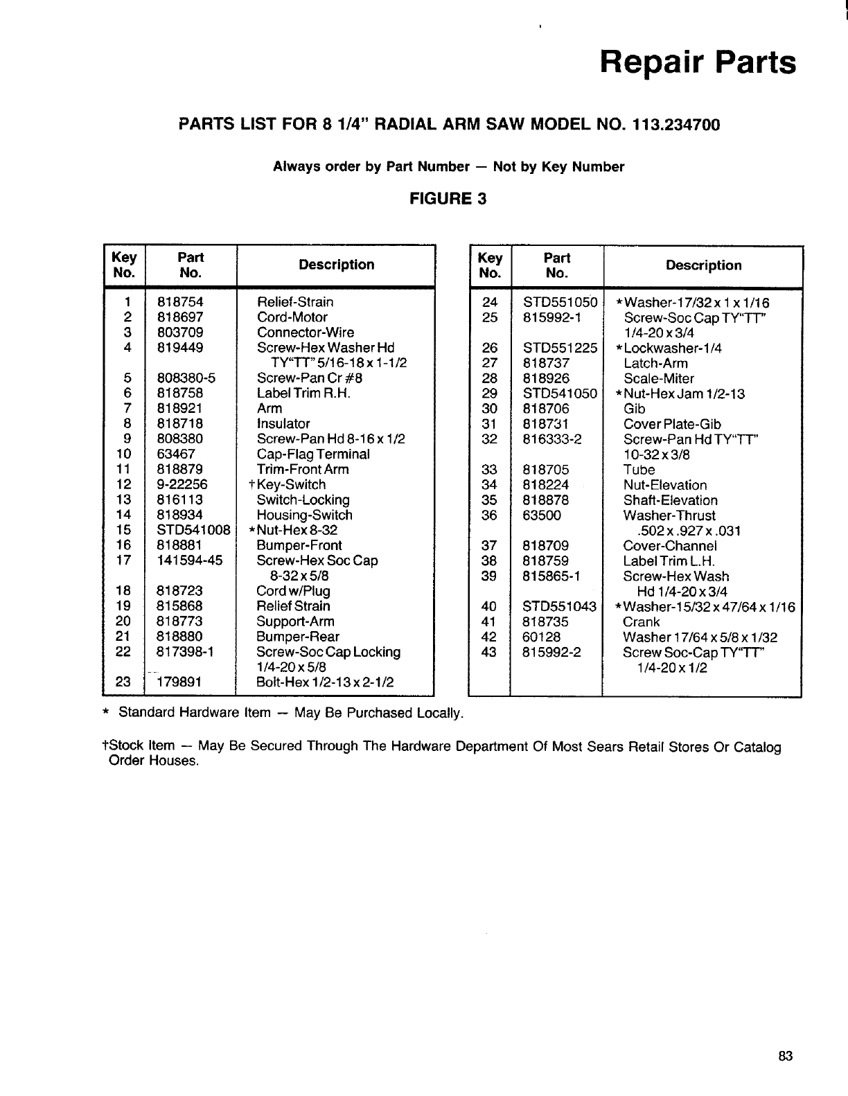
Repair Parts
PARTS LIST FOR 8 1/4" RADIAL ARM SAW MODEL NO. 113.234700
Always order by Part Number -- Not by Key Number
FIGURE 3
Key Part Description
No. No.
1
2
3
4
818754
818697
803709
819449
5808380-5
6818758
7818921
8 818718
9808380
10 63467
11 818879
12 9-22256
13 816113
14 818934
15 STD541008
16 818881
17 141594-45
18 818723
19 815868
20 818773
21 818880
22 817398-1
23 --i79891
Relief-Strain
Cord-Motor
Connector-Wire
Screw-Hex Washer Hd
TY"TT" 5/16-18 x 1-1/2
Screw-Pan Cr #8
Label Trim R.H.
Arm
Insulator
Screw-Pan Hd 8-16 x 1/2
Cap-Flag Terminal
Trim-Front Arm
t Key-Switch
Switch-Locking
Housing-Switch
*Nut-Hex 8-32
Bumper-Front
Screw-Hex Soc Cap
8-32 x 5/8
Cord w/Plug
Relief Strain
Support-Arm
Bumper-Rear
Screw-Soc Cap Locking
1/4-20 x 5/8
Bolt-Hex 1/2-13 x 2-1/2
Key Part Description
No. No.
24 STD551050
25 815992-1
26 STD551225
27 818737
28 818926
29 STD541050
30 818706
31 818731
32 816333-2
33 818705
34 818224
35 818878
36 63500
37 818709
38 818759
39 815865-1
40 STD551043
41 818735
42 60128
43 815992-2
*Washer-17/32 x 1x1/16
Screw-Soc Cap TY"-FT"
1/4-20 x 3/4
*Lockwasher- 1/4
Latch-Arm
Scale-Miter
*Nut-HexJam 1/2-13
Gib
Cover Plate-Gib
Screw-Pan Hd TY"TT"
10-32 x 3/8
Tube
Nut-Elevation
Shaft-Elevation
Washer-Thrust
,502 x .927 x .031
Cover-Channel
Label Trim LH,
Screw-Hex Wash
Hd 1/4-20 x 3/4
*Washer-15/32 x 47/64 x 1/16
Crank
Washer 17/64 x 5/8 x 1/32
Screw Soc-Cap TY"TT"
1/4-20 x 1/2
*Standard Hardware Item -- May Be Purchased Locally.
tStock Item -- May Be Secured Through The Hardware Department Of Most Sears Retail Stores Or Catalog
Order Houses.
83
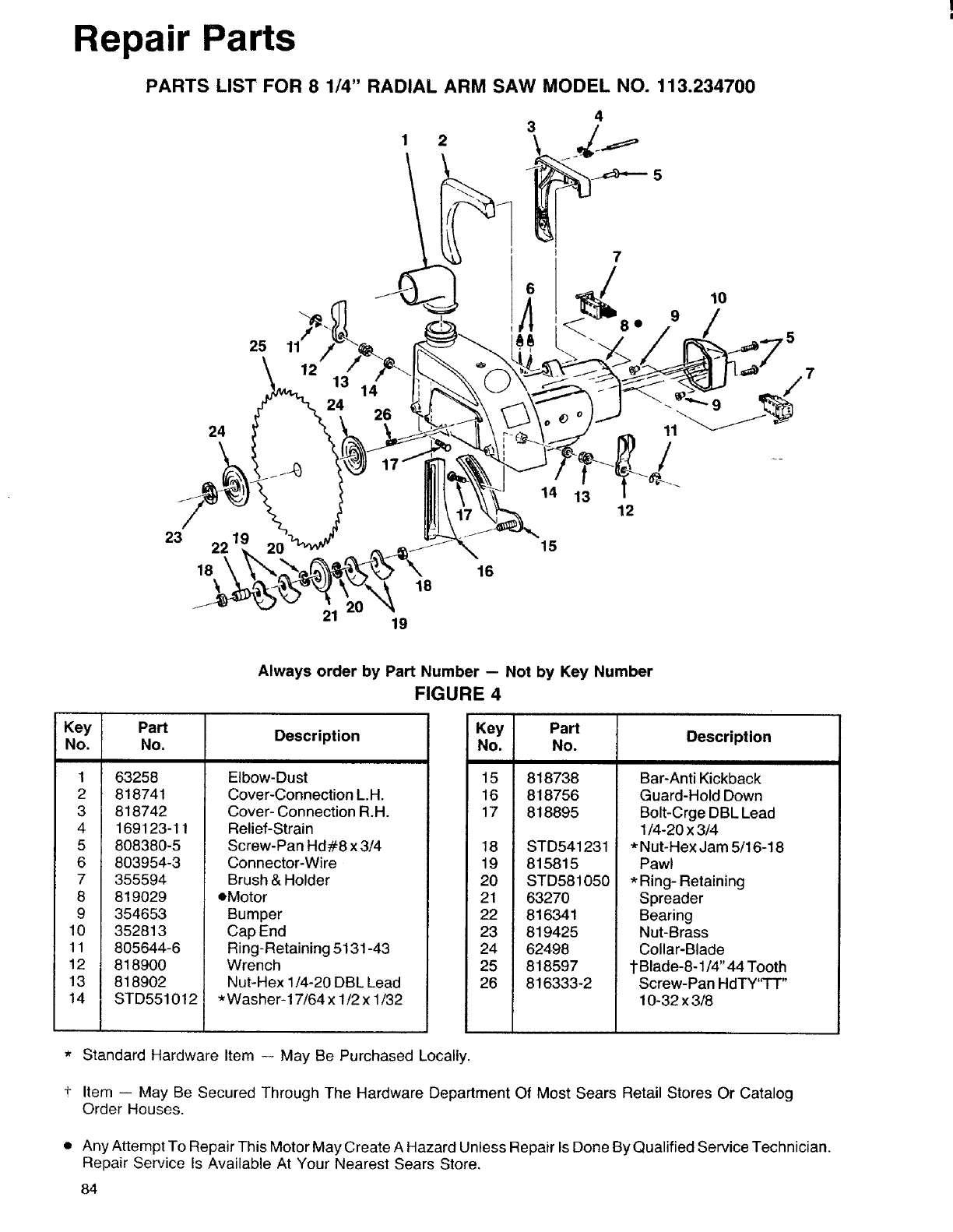
Repair Parts
PARTS LIST FOR 8 1/4" RADIAL ARM SAW MODEL NO. 113.234700
24
25
1
24 26
2
/_ 109
•/5
23 22 1
18
21
18
19
16
15
12
Always order by Part Number -- Not by Key Number
FIGURE 4
Key Part Description
No. No.
1 63258
2 818741
3 818742
4 169123-11
5 808380-5
6 803954-3
7 355594
8 819029
9 354653
10 352813
11 805644-6
12 818900
13 818902
14 STD551012
Elbow-Dust
Cover-Connection L.H.
Cover- Connection R.H.
Relief-Strain
Screw-Pan Hd#8 x 3/4
Connector-Wire
Brush & Holder
eMotor
Bumper
Cap End
Ring-Retaining 5131-43
Wrench
Nut-Hex 1/4-20 DBL Lead
*Washer-17/64 x 1/2 x 1/32
Key Part Description
No. No.
15 818738
16 818756
17 818895
18 STD541231
19 815815
20 STD581050
21 63270
22 816341
23 819425
24 62498
25 818597
26 816333-2
Bar-Anti Kickback
Guard-Hold Down
Bolt-Crge DBL Lead
1/4-20 x 3/4
*Nut-Hex Jam 5/16-18
Pawl
*Ring- Retaining
Spreader
Bearing
Nut-Brass
Collar-Blade
1Blade-8-1/4" 44 Tooth
Screw-Pan HdTY'q-I"
10-32 x 3/8
+
Standard Hardware Item -- May Be Purchased Locally.
Item -- May Be Secured Through The Hardware Department Of Most Sears Retail Stores Or Catalog
Order Houses.
Any Attempt To Repair This Motor May Create A Hazard Unless Repair Is Done By Qualified Service Technician.
Repair Service Is Available At Your Nearest Sears Store.
84

|
NOTES
85

NOTES
86
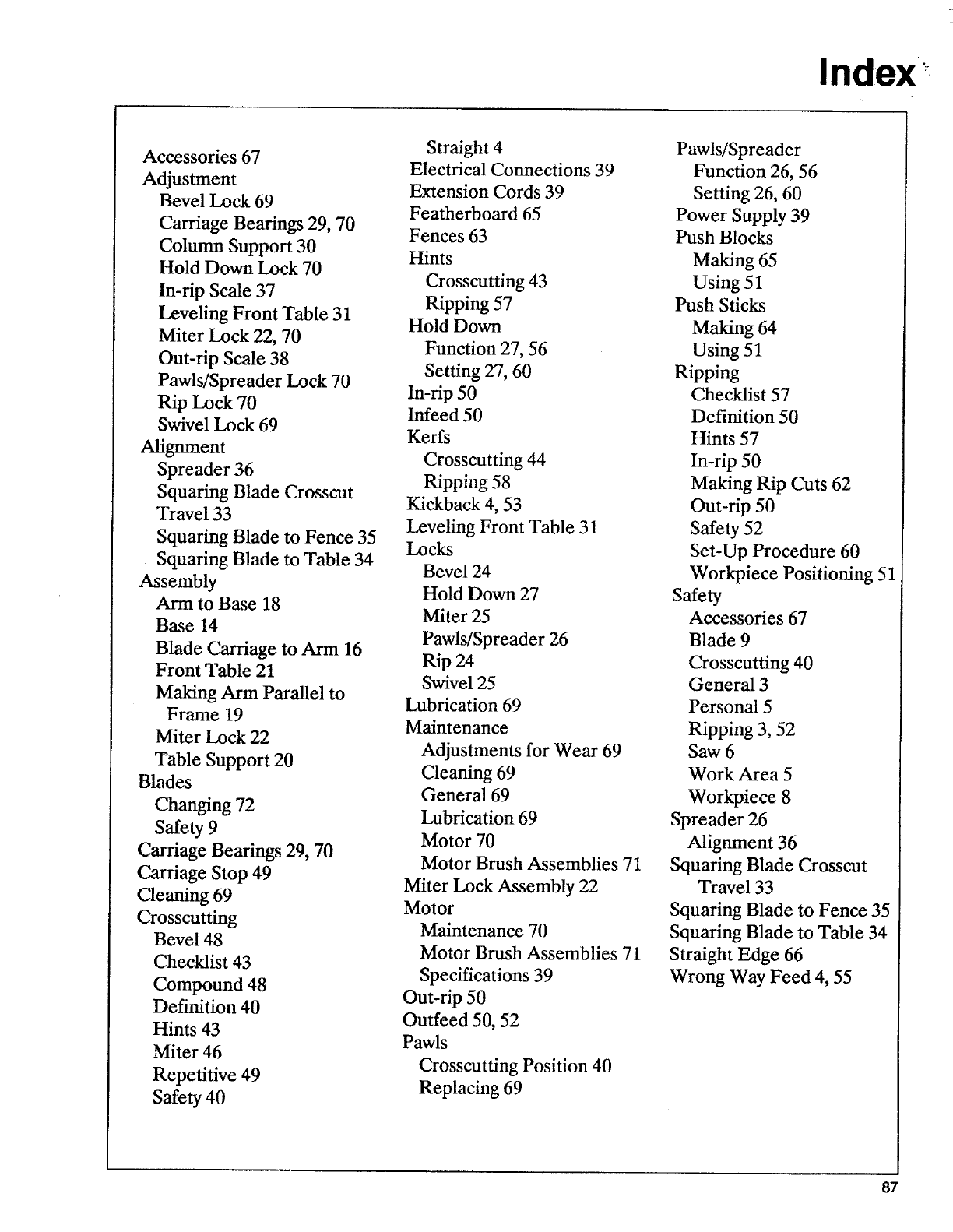
Index
Accessories 67
Adjustment
Bevel Lock 69
Carriage Bearings 29, 70
Column Support 30
Hold Down Lock 70
In-rip Scale 37
Leveling Front Table 31
Miter Lock 22, 70
Out-rip Scale 38
Pawls/Spreader Lock 70
Rip Lock 70
Swivel Lock 69
Alignment
Spreader 36
Squaring Blade Crosscut
Travel 33
Squaring Blade to Fence 35
Squaring Blade to Table 34
Assembly
Arm to Base 18
Base 14
Blade Carriage to Arm 16
Front Table 21
Making Arm Parallel to
Frame 19
Miter Lock 22
Table Support 20
Blades
Changing 72
Safety 9
Carriage Bearings 29, 70
Carriage Stop 49
Cleaning 69
Crosscutting
Bevel 48
Checklist 43
Compound 48
Definition 40
Hints 43
Miter 46
Repetitive 49
Safety 40
Straight 4
Electrical Connections 39
Extension Cords 39
Featherboard 65
Fences 63
Hints
Crosscutting 43
Ripping 57
Hold Down
Function 27, 56
Setting 27, 60
In-rip 50
Infeed 50
Kerfs
Crosscutting 44
Ripping 58
Kickback 4, 53
Leveling Front Table 31
Locks
Bevel 24
Hold Down 27
Miter 25
Pawls/Spreader 26
Rip 24
Swivel 25
Lubrication 69
Maintenance
Adjustments for Wear 69
Cleaning 69
General 69
Lubrication 69
Motor 70
Motor Brush Assemblies 71
Miter Lock Assembly 22
Motor
Maintenance 70
Motor Brush Assemblies 71
Specifications 39
Out-rip 50
Outfeed 50, 52
Pawls
Crosscutting Position 40
Replacing 69
Pawls/Spreader
Function 26, 56
Setting 26, 60
Power Supply 39
Push Blocks
Making 65
Using 51
Push Sticks
Making 64
Using 51
Ripping
Checklist 57
Definition 50
Hints 57
In-rip 50
Making Rip Cuts 62
Out-rip 50
Safety 52
Set-Up Procedure 60
Workpiece Positioning 51
Safety
Accessories 67
Blade 9
Crosscutting 40
General 3
Personal 5
Ripping 3, 52
Saw 6
Work Area 5
Workpiece 8
Spreader 26
Alignment 36
Squaring Blade Crosscut
Travel 33
Squaring Blade to Fence 35
Squaring Blade to Table 34
Straight Edge 66
Wrong Way Feed 4, 55
87
f
_ARS
owner's
manual
SERVICE
MODEL NO.
113.234700
8¼-INCH
RADIAl. SAW
HOW TO ORDER
REPAIRPARTS
8¼-1NCH
RADIAL SAW
Now that you have purchased your 8_/4-inch radial saw,
should a need ever exist for repair parts or service, simply
contact any Sears Service Center and most Sears, Roebuck
and Co. store_ Be sure to provide all pertinent facts when
you call or visit.
The model number of your 8_/4-inch radial saw will be found
on a plate attached to your saw, at the Rear of the base.
WHEN ORDERING REPAIR PARTS,ALWAYS GIVE THE FOLLOWING
INFORMATION'.
PARTNUMBER
MODELNUMBER
113.234700
PARTDESCRIPTION
NAMEOFITEM
8Y4-1NCHRADIALSAW
All parts listed may be ordered from any Sears Service Center
and most Sears stores If the parts you need are not stocked
locally, your order will be electronically transmitted to a Sears
Repair Parts Distribution Center for handling.
Sold by SEARS, ROEBUCK AND CO., Chicago, IL 60684 U.S.A.
Part No. SP5300 Form No. SP5300 Printed In LLS.A. 6/90
