Craftsman 113235100 User Manual 10 INCH MITER SAW Manuals And Guides L0806852
CRAFTSMAN Miter Saw Manual L0806852 CRAFTSMAN Miter Saw Owner's Manual, CRAFTSMAN Miter Saw installation guides
User Manual: Craftsman 113235100 113235100 CRAFTSMAN 10 INCH MITER SAW - Manuals and Guides View the owners manual for your CRAFTSMAN 10 INCH MITER SAW #113235100. Home:Tool Parts:Craftsman Parts:Craftsman 10 INCH MITER SAW Manual
Open the PDF directly: View PDF ![]() .
.
Page Count: 32

Save This Manual
For Future Reference
SEARS
owner's
manual
MODEL NO.
113.235200
COMPOUND MITER SAW
MODEL NO.
113.235100
NON-COMPOUND MITER
SAW
Serial
Number
Model and serial number
_o_oo,oonoonooa*o S_/A-.I_S/CRRFTSMRN
attached to you_ saw, at
the side of the Miter Saw
arm.
Voushou,OrecorObo_h 10 INCH MITER SAW
mode! and serial number in
a safe place for future use,
FOR YOUR
SAFETY:
READ ALL
INSTRUCTIONS
CAREFULLY
•assembly
•operating
•repair parts
Sears, Roebuck and Co., Hoffman Estates, IL 60179 U.S.A.
Part No. SP5763 Form No, SP5763-2
./
Printed in USA 8/96
f
if" FULL ONE YEAR WARRANTY ON CRAFTSMAN MITER SAW
If within one year from the date of purchase, this Craftsman Miter Saw fails due to a defect in
material or workmanship, Sears will repair it, free of charge.
Warranty service is available by simply contacting the nearest Sears service center/department
throughout the United States.
This warranty applies only while this product is used in the United States.
This warranty gives you specific legal rights, and you may also have other rights which vary
from state to state.
__ Sears, Roebuck and Co., D/817 WA Hoffman Estates, IL 60179
Safety Instructions for Miter Saw
Safety is a combination of common sense, staying alert
and knowing how your miter saw works. Read this
manuaI to understand this miter saw.
SAFETY SIGNAL WORDS
_, DANGER: If the safety information is not followed,
someone Will be seriously injured or killed.
WARNING: If the safety information is net fol-
lowed, someone Could be seriously injured or killed.
CAUTION: If the safety information is not followed,
someone May be injured.
Before Using The Saw:
I
WARNING: To avoid mistakes that could cause I
serious, permanent injury, do not plug the miter I
saw in until the following steps have been satis-
factorily completed.
Completely assemble and align saw. (See
"Assembly" and "Alignment" sections within).
Learn the use and function of the trigger switch,
upper and lower blade guards, stop shaft, bevel lock
knob (Model 113.235200 only) and cover plate stop
screw (see "Getting to Know your Miter Saw" section
within.)
Review and understand all safety instructions and
operating procedures in this manual.
Review the maintenance methods for this miter saw.
(See "Maintenance" section within).
Find and Read the following labels on the miter saw:
WARNING !ADVERTENCIA
When Installing Or Moving The Miter Saw:
• Before moving the saw, lock the miter, bevel and
power head positions. Unplug the power cord.
• To avoid back injury, get help when you need to lift
the saw.
• Never carry the tool by the cord or power head
switch handle. Damage to insulation could cause an
electric shook. Damage to wire connections could
cause a fire. A carry handle is provided.
Avoid Dangerous Environment.
•Use the miter saw in a dry, indoor place protected
from rain,
Keep work area well bighted.
Place the saw so neither the user nor bystanders are
forced to stand in line with the blade. Thrown debris
could injure people in its path.
To avoid injury from unexpected saw movement:
Put the miter saw on a firm level surface where there
is plenty of room for handling and properly support-
ing the workpiece.
Support the miter saw so the table is level and the
saw does not rock.
Bolt or clamp the miter saw to its support.
Never Stand On Tool. Serious injury could occur if
the tool tips or you accidentally hit the cutting tool.
Do not store anything above or near the tool where
anyone might stand on the tool to reach them.
To avoid injury or death from electrical shock:
•This Tool Is Double Insulated to give you added
protection. Double insulation does not take the place
or normal safety precautions when operating this
tool. When servicing this double insulated toot, use
only identical parts.
• Make sure your fingers do not touch the plug's metal
prongs when plugging or unplugging the miter saw
2
Before Each Use:
Inspect your miter saw.
• Disconnect The Miter Saw to avoid injury from
accidental starting before changing the setup,
changing the blade or adjusting anything.
• Compare the direction of rotation arrow on the guard
to the direction arrow on the blade. The blade teeth
should always point downward at the front of the
saw.
• Tighten the arbor screw.
• Tighten the cover plate stop screw.
Check For Damaged Parts. Check for:
Proper alignment of moving parts,
Damaged electric cords,
Binding of moving parts,
Broken parts,
Stable mounting,
Function of arm return spring and lower guard: Push
the arm all the way down, then let it rise up until it
stops by itself. Check the lower guard to see if it
closed fully, If it did not, follow the instructions in the
"TroubIe Shooting" section.
• Other conditions that may affect the way the miter
saw works.
If any part of this miter saw is missing, bent, or broken
in any way, or any electrical parts don't work, turn the
saw off and unplug it. Replace damaged, missing, or
failed parts before using the saw again.
Keep Guards In Place, in working order, and in proper
adjustment.
Maintain Tools With Care, Keep the miter saw clean
for best and safest performance. Follow instructions for
lubricating. DON'T put lubricants on the blade while it's
spinning.
Remove Adjusting Wrench and return it to proper
storage location on tool.
To avoid injury from jams, slips or thrown pieces:
Use Only Recommended Accessories. (See
"Accessory" section within). Consult this Owner's
manual for recommended accessories. Follow the
instructions that come with the accessories, The use
of improper accessories may cause risk of injury to
persons.
Choose the right 10-inch diameter blade for the
material and the type of cutting you plan to do.
Make sure the btade is sharp, undamaged and prop-
erly aligned. With the saw unplugged, push the
power head all the way down. Hand spin the blade
and check for clearance. Tilt the power-head to 45
degree bevel and repeat the check.
Make sure the blade and arbor collars are clean
Make sure the collars' recessed sides are facing the
blade.
Using t/4 inch allen wrench supplied, make sure the
arbor cap screw is firmly tightened.
Make sure all clamps and locks are tight and there is
no excessive play in any earls
•Keep Work Area Clean Cluttered areas and
benches invite accidents Floor must not be slippery.
To avoid burns or other fire damage, never use the saw
near flammable liquids, vapors or gases.
Plan ahead to protect your eyes, hands, face, ears.
Know Your Miter Saw. Read and understand the
owner's manuai and labels affixed to the tool. Learn its
applications and limitations as well as the specific
potential hazards peculiar to this tool,
To avoid injury from accidental contact with moving
parts, don't do layout, assembly, or setup work on the
miter saw while any parts are moving.
Avoid Accidental Starting. Make sure switch is "OFF"
before plugging miter saw into a power outlet.
Plan your work.
Use The Right Tool. Don't force tool or attachment to
do a job it was not designed to do. Use a different tool
for any workpiece that can't be held in a solidly braced,
fixed position.
CAUTION: This machine is not designed for
cutting ferrous metals (steel, iron and iron
based metals). Use this miter saw to cut only
wood, wood like products or soft metals like
aluminum. Other material may shatter, bind on
the blade, or create other dangers.
CAUTION: When cutting any metals, sparks or
hot fragments could cause a fire. To avoid this,
disconnect any dust collecting bag or hose
from the miter saw, and remove all traces of
wood dust from inside dust traps in the miter
saw.
Dress For Safety
WEARYOUR
Any power miter saw can throw foreign objects into the
eyes. This can result in permanent eye damage. Wear
safety goggles (not glasses) that comply with ANSI
Z87.1 (shown on package). Everyday eyeglasses have
only impact resistant lenses. They are not safety glass-
es. Safety goggles are available at Sears retain stores,
Glasses or goggles not in compliance with ANSI Z87.1
could seriously hurt you when they break,
*Do not wear loose clothing, gloves, neckties or jew-
elry (rings, wrist watches) They can get caught and
draw you into moving parts.
. Wear nonslip footwear.
• Tie back long hatr.
• Roll long sleeves above the elbow.
• Noise levels vary widely. To avoid possible hearing
damage, wear ear plugs or muffs when using miter
saw for hours at a time.
• For dusty operations, wear a dust mask along with
safety goggles.
Safety Instructions For Miter Saws (Continued)
Inspect your workpiece.
• Make sure there are no nails or foreign objects in the
part of the workpiece to be cut
Plan your work to avoid thrown pieces caused -
when the workpiece binds on the blade and is torn
from your hands.
Plan the way you will hold the workpiece from start to
finish:
Avoid awkward operations and hand positions where a
sudden slip could cause fingers or hand to move into
the blade.
Don't Overreach. Keep good footing and balance
Keep your face and body to one side of saw blade, out
of line with a possible throwback
Never cut Freehand:
• Cut only one workpiece at a time
• Brace your workpiece solidly against the fence and
table top so it will not rock or twist during the cut.
• Make sure there's no debris between the werkpiece
and its supports.
• Make sure no gaps between the workpiece fence
and table wit! let the workpiece shift after it is cut in
two
• Keep the cut off piece free to move sideways after
it's cut off. Otherwise it could get wedged against the
biade and could be thrown violently.
• Clear everything except the workpiece ann related
support devices off the table before turning the miter
saw on
• Secure Work. Use clamps or a vpseto help hold the
work when it's practical
Use extra caution with large, very small or awkward
workpieces:
Use extra supports (tables, saw horses blocks, etc.)
for any workpiece large enough to tip when not held
down to the table top.
Never use another person as a substitute fo_ a table
extension, or as additiona! support for a workpiece
tnat is longer or wider than the basic miter saw table
Do not use this saw to cut pieces too small to iet you
easiIy hold the work. The thumb side of your index
(pointer) finger should not be closer to the blade than
toe outside edge of the fence
When cutting irregularly shaped workpieces plan
your work so it will not slip and pinch the blade anu
be torn from your hands, A piece of molding, for
example, must lie fiat or be held by a fixture or jig
that wili not !et ittwist, rock or slip while being cut
Properly support round material such as dowei rods
.,r tubing. They have a tendency to rol! whie bein9
cuL causing the blade to "bite" To avoid this a!wey_.
_se a fixture designed to properly hold your work
oiece
WARNING: If planning to cut aluminum or other
non-ferrous metals: Under adverse conditions,
the blade can grab and throw the workpiece
suddenly and unexpectedly. To avoid injury,
follow all applicable safety instructions, as you
normally would, and:
Use only sawblades specifically recom-
mended for non-ferrous metal cutting,
Do not cut metal workpieces that must be
hand held. Use auxiliary clamps or other
equipment as needed.
Cut non-ferrous metals only if you are expe-
rienced or under the supervision of an expe-
rienced person.
Whenever Saw Is Running:
WARNING: Don't allow familiarity (gained from
frequent use of your miter saw) cause a care-
less mistake. A careless fraction of a second is
enough to cause a severe injury.
4
Before starting your cut, watch the miter saw while
runs If it makes an unfamiliar noise or vibrates a lot,
stop immediateIy. Turn the saw off. Unplug the saw. Do
not restart until finding and correcting the problem
Keep Children Away. Keep all visitors a safe distance
from the miter saw. Make sure bystanders are clear of
the miter saw and workpiece
Never confine the p_ece being cut off Never hold it,
clamp it, touch it, or use length stops against it while the
bIade is spinning. It must be free to move sideways on
its own If confined, it could gel wedged against the
blade and thrown viotentiy.
Let the blade reach fbll speed before cutting
DOn't Force Tool. It will do the job better and safer at
its designed rate. Feed the saw into the werkpiece only
fast enough to tel the blade cut without bogg_ng down
or b riding
Before freeing jammed material:
Turn switch 'OFF"
Unp!ug the miter saw
Wait for all moving parts to stop
After finishing a cut:
Keep holding the power head down
Release the switch, and wait for all moving parts to
stop before moving your hands.
• if blade doesn't stop within 6 seconds, unpiug the
saw and follow the instructions in the 'Trouble
Shooting" section for fixing the blade brake before
using the saw again
Before Leaving The Saw:
Never Leave Tool Running Unattended. Turn power
off Wait for aii moving parts to stop
Make workshop chiid-proof Lock the shop Disconnect
master switches Store tool away from ct_ildren and oth
era not qualified to use the tool
Glossary of Terms for Woodworking
Arbor Miter Cut
The shaft on which acutting toot is mounted, An angle cutting operation made across the width of the
Bevel Cut workplace.
An angle cutting operation made throughthe face of the Resin
workpiece. A sticky, sap based substance that has hardened.
Compound Cut
A simultaneous bevel and miter cutting operations.
Crosscut
A cutting operation made across the width of the work-
piece.
Freehand
Performing a cut without using a fence (guide), hold
down or other proper device to prevent the workpiece
from twisting during the cutting operation. Twisting of
the workpiece can cause it to be thrown.
Revolutions Per Minute (RPM)
The number of rums completed by a spinning object in
one minute,
Sawbl_le Path
The area of the workpiece or table top directly in line
with either the travel of the blade or the part of the work-
piece which will be, or has been, cut by the blade.
Set
The distance that the tip of the sawb_ade tooth is bent
(or set) outward from the face of the blade.
Gum
A sticky, sap based residue from wood products.
Heel
Misalignment of the blade.
Kerr
The amount of material removed by the blade in a
through cut or the slot produced by the blade in a non-
through or partial cut.
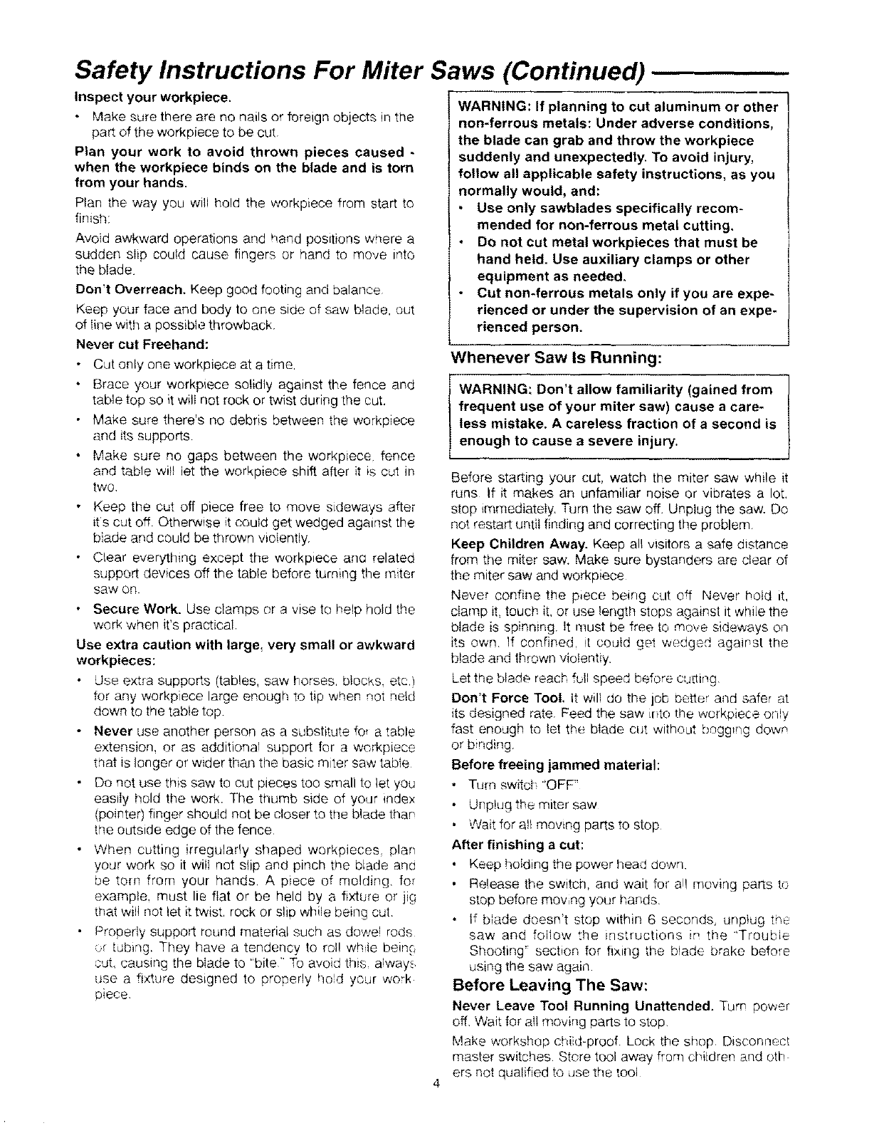
Workpiece
The item on which the cutting operation is being per-
formed. The surfaces of a workpiece are commonly
referred to as faces, ends, and edges.
FACE
EDGE
Motor Specifications and Electrical Requirements
Power Supply and Motor Specifications
The AC motor used in this saw is a universal, nonre-
versible type having the following specifications:
i Maximum Developed H.P.
Voltage
Amperes
Hertz (Cycles)
Phase
RPM
Shaft Rotation (blade end)
MODEL
113.235100
2
120
12
60
Single
5O0O
Clockwise
MODEL
113.235200
3
120
15
6O
Single
52O0
Clockwise
WARNING: To avoid electrical hazards, fire haz-
ards, or damage, or damage to the tool, use prop*
er circuit protection. Your saw is wired at the fac-
tory for 120v operation. Connect to a 120v, 15-
amp branch circuit and use a 15-amp time delay
fuse or circuit breaker. To avoid shock or fire, if
power cord is worn or cut, or damaged in any
way, have it replaced immediately.
Double Insulated
The miter saw is double insulated to provide a double
thickness of insuletion between you and the tool's elec-
trical system. All exposed metal parts are isolated from
the internal metal motor components with protecting
insulation.
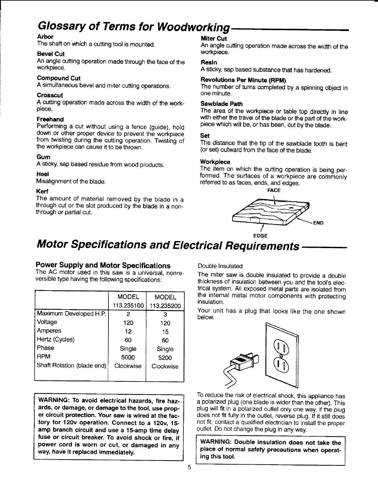
Your unit has a plug that looks like the one shown
below,
5
To reduce the risk of electrical shock, this appliance has
a polarized plug (one blade is wider than the other). This
plug will fit in a polarized outlet only one way, ff the plug
does not fit fully in the outlet, reverse plug. If it still does
not fit, contact a qualified electrician to install the proper
out_et. Do not change the plug in any way.
WARNING: Double insulation does not take the
place of normal safety precautions when operat-
ing this tool.
Motor Specifications and Electrical Requirements (Continued)
DANGER: To avoid electrocution:
1, Use only identical replacement parts when
servicing a tool with double insulation.
Servicing should be performed by a qualified
service technician,
2. Do not use in rain or where floor is wet.
This tool is intended for indoor residential use
only.
Motor Safety Protection
IMPORTANT: To avoid motor damage, this motor
should be blown out or vacuumed frequently to keep
sawdust from interfering with normal motor ventilation.
1. Connect this tool to a 120v, 15-amp branch circuit
with a 15-amp time delay fuse or circuit breaker.
Using the wrong size fuse can damage the motor.
2. If the motor won't start, release the trigger switch
immediately. UNPLUG THE TOOL. Check the saw
blade to make sure it turns freely, if the blade is free,
try to start the motor again. If the motor still does not
start, refer to the "Motor Trouble-Shooting Chart."
3. If the motor suddenly stalls while cutting wood,
release the trigger switch, unplug the tool, and free
the blade from the wood. The motor may now be
restarted and the cut finished.
4. Fuses may "blow" or circuit breakers may trip fre-
quently it:
a. Motor Is Overloaded-Overloading can occur if
you feed too rapidly or make too many start/stops
in a short time.
b. Line voltages are more than 10% above or below
the nameplate voltage. For heavy loads, however,
the voltage at motor terminals must equal the volt-
age specified on nameplate.
5. Most motor troubles may be traced to loose or incor
rect connections, overload, tow voltage (such as
small size wire in the supply circuit) or to overly long
supply circuit wire. Always check the connections.
the load and the supply circuit whenever motor
doesn't work well. Check wire sizes and length with
the Wire Size Chart below.
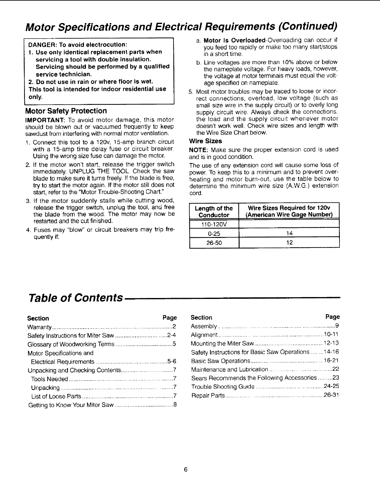
Wire Sizes
NOTE: Make sure the proper extension cord is used
and is in good condition.
The use of any extension cord will cause some loss of
power. To keep this to a minimum and to prevent over-
heating and motor burn-out, use the table below to
determine the minimum wire size (A.W.G) extension
cord.
Length of the Wire Sizes Required for 120v
Conductor {American Wire Gage Number)
110-120V
0-25 14
26-50 12
Table of Contents
Section Page
Warranty .......................................................................... 2
Safety Instructions for Miter Saw ............................... 2_4
Glossary of Woodworking Terms ................................... 5
Motor Specifications and
Electrical Requirements ............................................ 5-6
Unpacking and Checking Contents ................................ 7
Tools Needed ................................................................ 7
Unpacking ................................................................ 7
List of Loose Parts ........................................................ 7
Getting to Know Your Miter Saw .................................... 8
Section Page
Assembly .................................................................. 9
Alignment ............................................................. 10-1!
Mounting the Miter Saw .......................................... ! 2-13
Safety Instructions for Basic Saw Operations ....... 14-16
Basic Saw Operations ............................................ 16-21
Maintenance and Lubrication .................................. 22
Sears Recommends the Following Accessories ........ 23
Trouble Shooting Gu*de ........................................ 24-25
Repair Parts .......................................................... 26-31
6
Unpacking and Checking Contents
Tools Needed
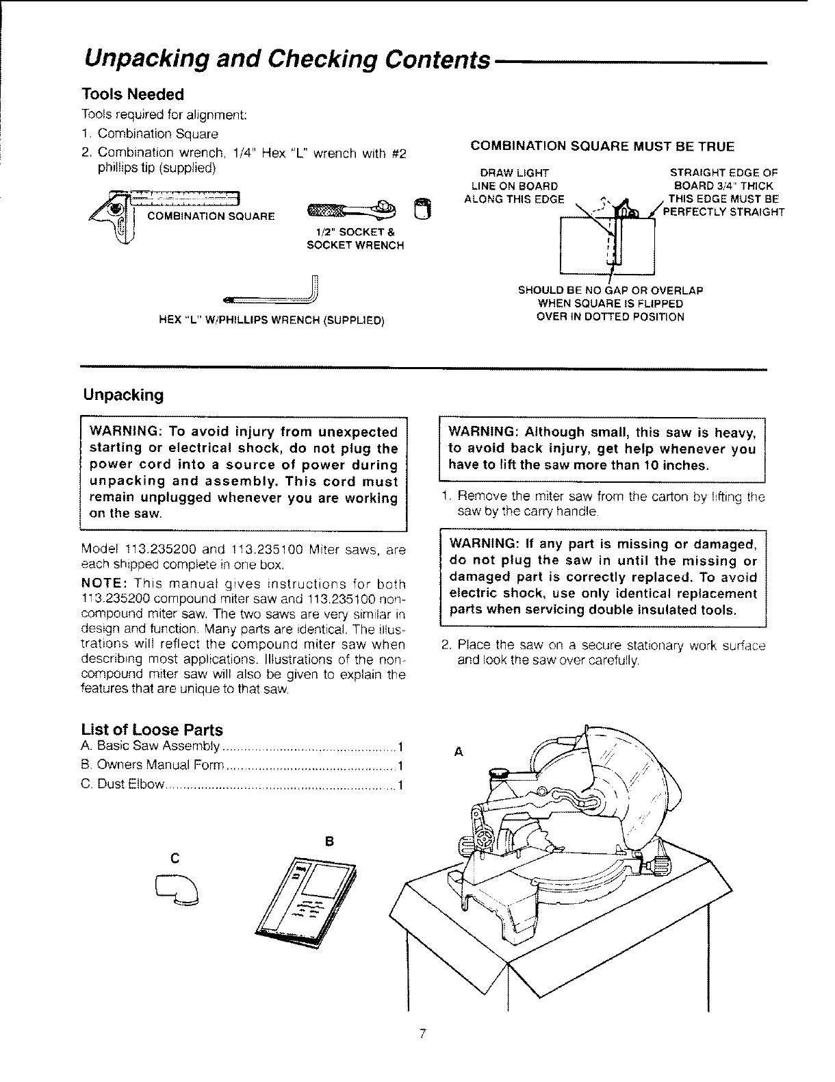
Tools required for alignment:
1 Combination Square
2. Combination wrench, 1/4" Hex "L" wrench with #2
phillips tip (supplied)
MBINATION S_UARE 1/2" SOCKET &
SOCKET WRENCH
HEX "L" W/PHILLIPS WRENCH (SUPPLIED)
COMBINATION SQUARE MUST BE TRUE
DRAW LIGHT STRAIGHT EDGE OF
LINE ON BOARD BOARD 3/4" THICK
ALONG THIS EDGE _, ,m THIS EDGE MUST BE
_,'°" '_ ///PERFECTLY STRAIGHT
SHOULD BE NO GAP OR OVERLAP
WHEN SQUARE IS FLIPPED
OVER IN DOTTED POSITION
Unpacking
WARNING: To avoid injury from unexpected
starting or electrical shock, do not plug the
power cord into a source of power during
unpacking and assembly. This cord must
remain unplugged whenever you are working
on the saw.
Model 113.235200 and !13.235100 Miter saws, are
each shipped complete in one box,
NOTE: This manual gwes instructions for both
113.235200 compound miter saw and 113.235100 non-
compound miter saw, The two saws are very similar in
design and function. Many parts are identical. The illus-
trations will reflect the compound miter saw when
describing most applications. Illustrations of the non-
compound miter saw will also be given to explain the
features that are unique to that saw,
WARNING: Although small, this saw is heavy,
to avoid back injury, get help whenever you
have to lift the saw more than 10 inches.
1. Remove the miter saw from the carton by Ifting the
saw by the carry handle
WARNING: If any part is missing or damaged,
do not plug the saw in until the missing or
damaged part is correctly replaced. To avoid
electric shock, use only identical replacement
parts when servicing double insulated tools,
2. Place the saw on a secure stationary work surface
and look t_e saw over carefully
List of Loose Parts
A. Basic Saw Assembly ................................................. 1
B, Owners Manual Form ................................................ 1
C Dust Elbow ................................................................. 1
A
B
7
Getting to Know Your Miter Saw
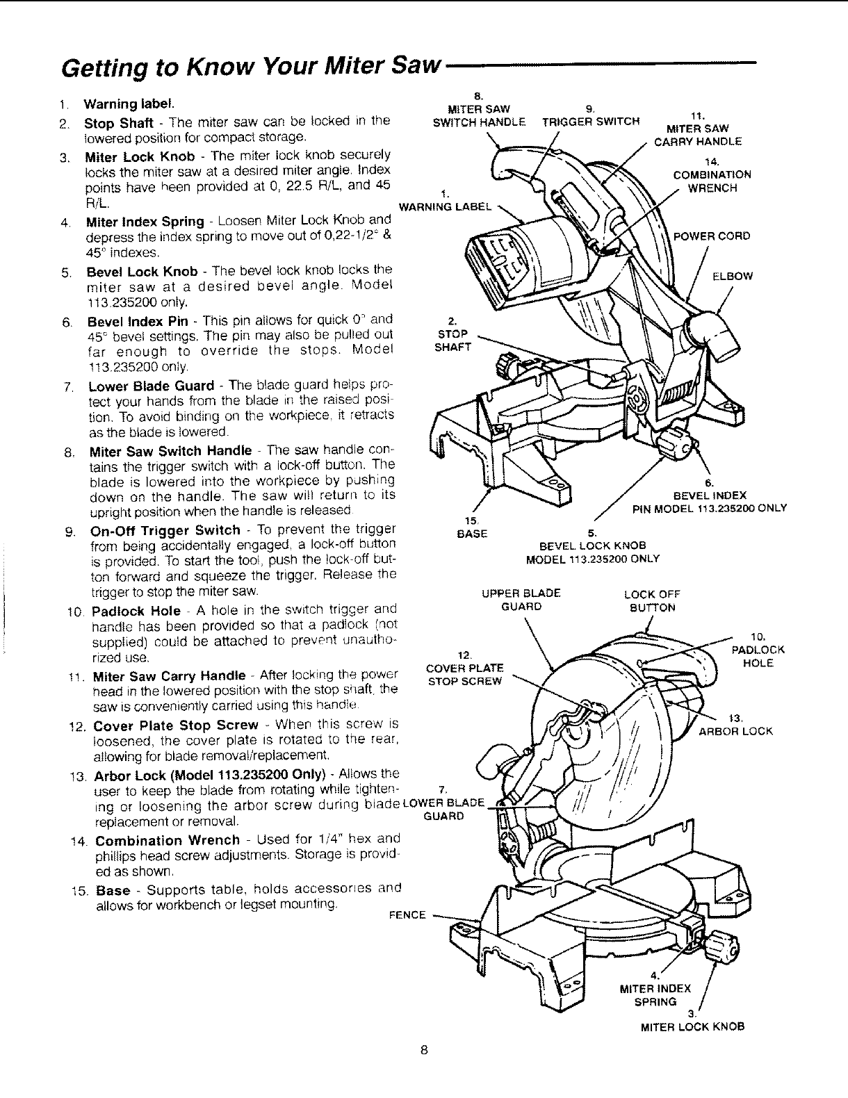
1. Warning label.
2. Stop Shaft - The miter saw can be locked in the
lowered position for compacl storage.
3, Miter Lock Knob - The miter lock knob securely
locks the miter saw at a desired miter angle, Index
points have heen provided at 0, 225 R/L, and 45
RiL.
4, Miter Index Spring Loosen Miter Lock Knob and
depress the index spring to move out of 0,22-1/2 ° &
45 ° indexes.
5. Bevel Lock Knob - The bevel Iock knob locks the
miter saw at a desired bevel angle. Model
113.235200 oniy.
6. Bevel Index Pin - This pin altows for quick 0 and
45° bevel settings. The pin may also be pulled out
far enough to override the stops. Model
113.235200 only.
7Lower Blade Guard - The blade guard helps pro
tect your hands from the blade in the raised posi
lion. To avoid binding on the workpiece it retracts
as the blade is lowered.
8. Miter Saw Switch Handle - The saw handle con-
tains the trigger switch with a lock-off buttcn. The
blade is lowered into the workpiece by pushing
down on the handle. The saw witl return to its
upright position when the handle is released
9. On-Off Trigger Switch -To prevent the trigger
from being accidentally engaged, a lock-off button
is provided. To start the tool, push the !ock-off but-
ton forward and squeeze the trigger. Release the
trigger to stop the miter saw.
10 Padlock Hole - A hole in the switch trigger and
handle has been provided so that a padlock (not
supplied) could be attached to prevent unautho-
rized use.
8.
MITER SAW
SWITCH HANDLE
t.
WARNING LABEL
15
BASE
1!. Miter Saw Carry Handle - After locking the power
head in the lowered position with the stop shaft the
saw is conveniently carried using this handle
12. Cover Plate Stop Screw - When this screw is
loosened, the cover plate is rotated to the rear,
allowing for blade removal/replacement,
13. Arbor Lock (Model 113.235200 Only) - Allows the
user to keep the blade from rotating while tighten- 7,
mg or loosening the arbor screw during bladeLOWER BLADE
replacement or removal. GUARD
14. Combination Wrench Used for !/4" hex and
phillips head screw adjustments, Storage is provid-
ed as shown.
15. Base - Supports table, holds accessories and
allows for workbench or legset mounting. FENCE
9,
TRIGGER SWITCH 11.
MITER SAW
CARRY HANDLE
14.
COMBINATION
WRENCH
POWER CORD
ELBOW
6.
BEVELINDEX
PiN MODELt13,235200ONLY
S.
BEVELLOCKKNOB
MODEL113.235200 ONLY
UPPER BLADE
GUARD
12.
COVER PLATE
STOP SCREW
LOCK OFF
BUTTON
SPRING
10.
PADLOCK
HOLE
13,
ARBOR LOCK
8
3.
MITER LOCK KNOB
Assembly
Removing or Installing the Blade
IWARNING: To avoid injury from a thrown work-
piece or thrown pieces of blade, do not use a
blade larger or smaller than 10" diameter,
1
1.
2.
WARNING: To avoid injury from unexpected
starting, unplug the saw whenever you are
removing or installing the blade.
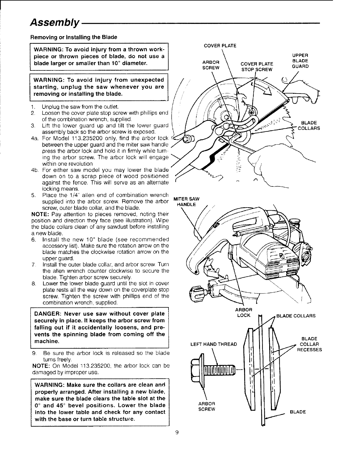
Unplug the saw from the outlet.
Loosen the cover plate stop screw with phillips end
of the combination wrench, supplied.
3. Lift the lower guard up and tilt the lower guard
assembly back so the arbor screw is exposed.
4a. For Model 1t3.235200 only, find the arbor lock
between the upper guard and the miter saw handle
press the arbor lock and hold it in firmly while turn-
ing the arbor screw. The arbor lock will
within one revolution
4b For either saw model you may lower the
down on to a scrap piece of wood positioned
against the fence. This will serve as an alternate
locking means.
5. Place the 1/4" allen end of combination wrench
supplied into the arbor screw. Remove the arbor
screw, outer blade collar, and the blade.
NOTE: Pay attention to pieces removed, noting their
position and direction they face (see illustration). Wipe
the blade collars clean of any sawdust before installing
a new blade.
6. Install the new 10" blade (see recommended
accessory list). Make sure the rotation arrow on the
blade matches the clockwise rotation arrow on the
upper guard.
7 Install the outer blade collar, and arbor screw. Turn
the allen wrench counter clockwise to secure the
blade. Tighten arbor screw securely.
8. Lower the lower blade guard until the slot in cover
plate rests all the way down on the coverplate stop
screw. Tighten the screw with phillips end of the
combination wrench, supplied.
DANGER: Never use saw without cover plate
securely in place. It keeps the arbor screw from
falling out if it accidentally loosens, and pre-
vents the spinning blade from coming off the
machine,
9. Be sure the arbor lock is released so the blade
turns freely.
NOTE: On Model _13.235200, the arbor lock can be
damaged by improper use.
/
MITER SAW
HANDLE
COVER PLATE
ARBOR
SCREW
ARBOR
LOCK
LEFT HAND THREAD
COVER PLATE
STOPSCREW
UPPER
BLADE
GUARD
BLADE
"COLLARS
BLADE COLLARS
BLADE
COLLAR
WARNING: Make sure the collars are clean and
properly arranged. After installing a new blade,
make sure the blade clears the table slot at the
0°and 450 bevel positions, Lower the blade
into the lower table and check for any contact
with the base or turn table structure.
ARBOR
SCREW BLADE
9
Assembly (continued)
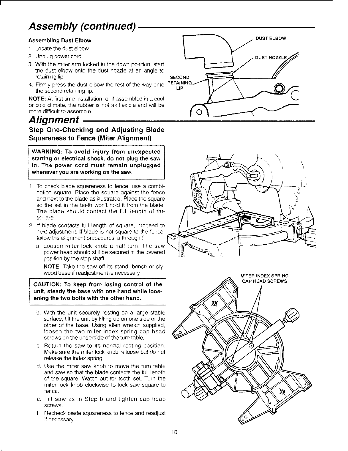
Assembling Dust Elbow
1, Locate the dust elbow.
2. Unplug power cord.
3. With the miter arm locked in the down position, start
the dust elbow onto the dust nozzle at an angle to
retaining lip.
4. Firmly press the dust elbow the rest of the way onto
the second retaining lip.
NOTE: At first time installation, or if assembled in a cool
or cold climate, the rubber is not as flexible and will be
more difficult to assemble.
Alignment
Step One-Checking and Adjusting Blade
Squareness to Fence (Miter Alignment)
SECOND
LIP
DUST ELBOW
IARNING: To avoid injury from unexpected I
starting or electrical shock, do not plug the saw
in. The power cord must remain unplugged
whenever you are working on the saw.
1. To check blade squareness to fence, use a combi-
nation square. Place the square against the fence
and next to the blade as illustrated. Place the square
so the set in the teeth won't hold it from the blade,
The blade should contact the full length of the
square.
2. tf blade contacts full length of square, prcceed to
next adjustment. If blade is not square to the fence
foIIow the alignment procedures: a through f.
a. Loosen miter lock knob a half turn The
power head should still be secured in the lowered
position by the stop shaft.
NOTE: Take the saw off its stand, bench or ply
wood base if readjustment is necessary
I CAUTION: To keep from losing control of the
unit, steady the base with one hand while !oos-
ening the two bolts with the other hand,
\\
MITER INDEX SPRING
CAP HEAD SCREWS
b.
C.
d.
e,
f
With the unit securely resting on a large stable
surface, tilt the unit by lifting up on one side or the
other of the base, Using allen wrench supplied,
loosen the two miter index spring cap head
screws on the underside of the turn table.
Return the saw to its normal resting position
Make sure the miter lock knob is loose but do not
release the index spring.
Use the miter saw knob to move the turn table
and saw so that the blade contacts the full length
of the square. Watch out for tooth set. Turn the
miter lock knob clockwise to lock saw square to
fence.
Tilt saw as in Step b and tighten cap head
screws,
Recheck blade squareness to fence and readjust
if necessary.
10
Alignment (continued)
Adjustment of Miter Scale Indicator
1. Loosen the phillips screw that holds the indicator in
place.
2. Reposition the indicator and retighten screw
WARNING: To avoid injury from unexpected
starting or electrical shock, do not plug the saw
in, The power cord must remain unplugged
whenever you are working on the saw,
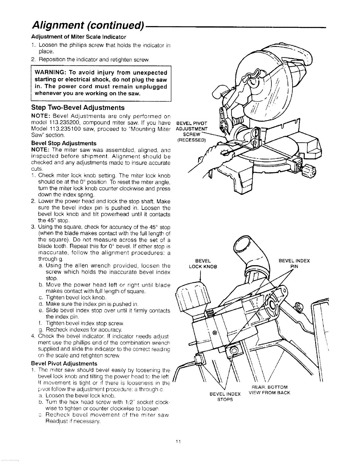
Step Two-Bevel Adjustments
NOTE: Bevel Adjustments are only performed on
model 113.235200, compound miter saw. If you have
Model 113.235100 saw, proceed to "Mounting Miter
Saw" section.
Bevel Stop Adjustments
NOTE: The miter saw was assembled, aligned, and
inspected before shipment Alignment should be
checked and any adjustments made to insureaccurate
cuts
1. Check miter lock knob setting. The miter lock knob
should be at the 0° position To reset the miter angle,
turn the miter lock knob counter clockwise and press
down the index spring.
2. Lower the power head and lock the stop shaft. Make
sure the bevel index pin is pushed in. Loosen the
bevel lock knob and tilt powerhead until it contacts
the 45° stop.
3. Using the square, check for accuracy of the 45 ° stop
(when the blade makes contact with the full length of
the square). Do not measure across the set of a
blade tooth. Repeat this for 0° bevel. If either stop is
inaccurate, follow the alignment procedures: a
through g.
a. Using the allen wrench provided, loosen the
screw which holds the inaccurate bevel index
stop.
b Move the power head left or right until blade
makes contact with full length of square.
c. Tighten bevel lock knob
d. Make sure the index pin =spushed in.
e. Slide bevel index stop over until it firmly contacts
the index pin
f Tighten bevel index stop screw.
g. Recheck indexes for accuracy.
4. Check the bevel indicator. If indicator needs adjust
ment use the phillips end of the combination wrench
supplied and slide the indicator to the correct reading
on the scale and retighten screw
Bevel Pivot Adjustments
I. The miter saw should bevel easily by loosening the
bevel lock knob and titting the power head to the left
if movement is tight or if there is looseness _nthe
p,vot follow the adjustment procedure: a through c
a Loosen the bevel lock knob.
b. Turn the hex head screw with 1/2" socket clock-
wise to tighten or counter clockwise to loosen
c Recheck bevel movement of the miter saw
Readjust if necessary
BEVEL PIVOT
ADJUSTMENT
(RECESSED)
BEVEL
LOCK KNOB
,q
BEVELINDEX
STOPS
BEVELINDEX
PIN
/
REAR, 8ofroM
VIEW FROM BACK
!1
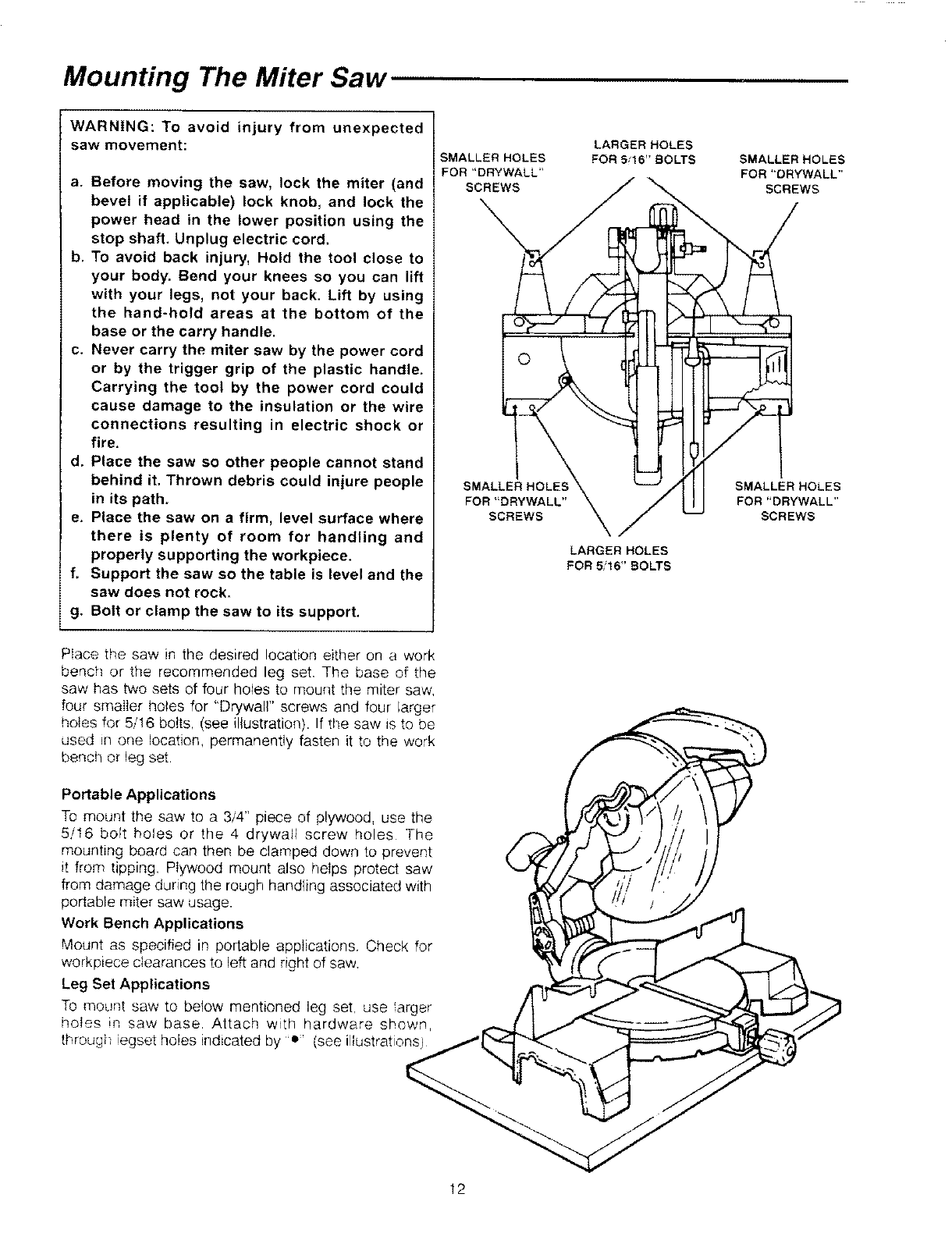
Mounting The Miter Saw
WARNING: To avoid injury from unexpected
saw movement:
a. Before moving the saw, lock the miter (and
bevel if applicable) lock knob, and lock the
power head in the lower position using the
stop shaft. Unplug electric cord.
b. To avoid back injury, Hold the tool close to
your body, Bend your knees so you can lift
with your legs, not your back. Lift by using
the hand-hold areas at the bottom of the
base or the carry handle.
c. Never carry the miter saw by the power cord
or by the trigger grip of the plastic handle,
Carrying the tool by the power cord could
cause damage to the insulation or the wire
connections resulting in electric shock or
fire.
d. Place the saw so other people cannot stand
behind it, Thrown debris could injure people
in its path.
e. Place the saw on a firm, level surface where
there is plenty of room for handling and
properly supporting the workpiece.
f, Support the saw so the table is level and the
saw does not rock,
g. Bolt or clamp the saw to its support.
SMALLER HOLES
FOR"DRYWALL'*
SCREWS
SMALLER HOLES
FOR"DRYWALL"
SCREWS
LARGER HOLES
FOR Si16"BOLTS
LARGER HOLES
FOR 5i16"SOLTS
SMALLER HOLES
FOR "DRYWALL"
SCREWS
SMALLER HOLES
FOR"DRYWALL"
SCREWS
Place the saw in the desired location either on a work
bench or the recommended leg set. The base of the
saw has two sets of four holes to mount the miter saw.
four smaller holes for 'Drywall" screws and four larger
holes for 5/16 bolts. (see illustration). If the saw Is to be
used in one location, permanently fasten it to the work
bench or leg set.
Portable Applications
To mount the saw to a 3/4" piece of plywood, use the
5/16 bolt holes or the 4 drywall screw holes The
mounting board can then be clamped down to prevent
it from tipping, Plywood mount also helps protect saw
from damage during the rough handling associated with
portable miter saw usage.
Work Bench Applications
Mount as specified in portable applications Check for
workpiece clearances to left and right of saw.
Leg Set Applications
To mount saw to below mentioned leg set. use arger
holes m saw base. Attach with hardware show,<
througi_ iegset holes indicated by e* (see iliustrations_
12
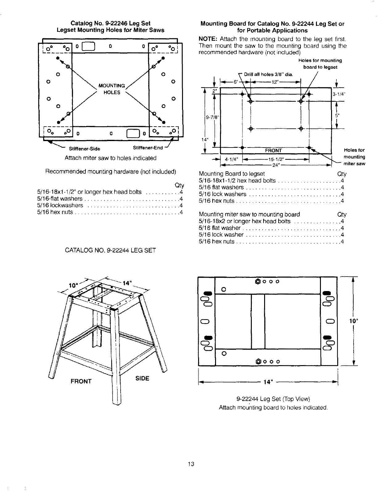
Catalog No, 9-22246 Leg Set
Legset Mounting Holes for Miter Saws
o
O
o
o
MOUNTING
Do DO
°oJ
o
o
o
o
/\
o 0 Do Oo oOI
Stiffener-Side Stiffener-End J
Attach miter saw to holes indicated
Recommended mounting hardware (not included)
Qty
5/16-18x! -1/2" or longer he)( head bolts ........... 4
5/16-flat washers .............................. 4
5/16 Iockwash ers ............................. 4
5/16 hex nuts ................................. 4
CATALOG NO. 9-22244 LEG SET
Mounting Board for Catalog No, 9-22244 Leg Set or
for Portable Applications
NOTE: Attach the moun_ing board to the leg set firsL
Then mount the saw to the mounting board using the
recommended hardware (not included)
Holes for mounting
board to legset
Drill all holes 3_8" dia. /
t/
:_,L\I / /_
9-7_
i__
3-!/4"
t
FRONT _-
_q4 mounting
-1/4" 15-1/2" ._------,_
24" w, miter saw
Mounting Board to legset Qty
5/16-18xl-1/2 hex head bolts .................... 4
5/16 flat washers .............................. 4
5/16 lock washers ............................. 4
5/16 hex nuts ................................. 4
Holes for
Mounting miter saw to mounting board Qty
5/1G18x2 or longer hex head bolts ............... 4
5/16 flat washer ............................... 4
5/16 lock washer .............................. 4
5/16 hex nuts ................................. 4
FRONT SIDE
g
CD
g
CD
_ooo
O
O
_0OO
Q
CD
CD
m
CD
CI)
14"
9-22244 Leg Set (Top View)
Attach mounting board to holes indicated
CC) 10"
13
Safety Instructions For Basic Saw Operations
Before Using The Miter Saw:
WARNING: To avoid mistakes that could cause
serious, permanent injury, do not plug the
miter saw in until the following steps are com-
pleted.
Completely Assemble and Align Saw, (See
"Assembly" and "Alignment" sections).
Learn the use and function of the ON-OFF switch,
upper and lower blade guards, stop shaft, bevel lock
knob (model 113.235200 only) and cover plate stop
screw. ("See Getting To Know Your Miter Saw"
Section.).
• Review and understand all safety instructions and
operating procedures in this manual.
• Review the maintenance methods for this miter saw.
(See Maintenance Section).
To avoid injury or death from electrical shock:
• Make sure your fingers do not touch the plug's metal
prongs when plugging or unplugging the miter saw.
BEFORE EACH USE:
Inspect you saw.
Disconnect The Miter Saw, To avoid injury from acci-
dental starting, unplug the saw, before changing the
setup, changing the blade or adjusting anything.
Compare the direction of rotation arrow on the guard to
the direction arrow on blade. The blade teeth shoutd
always point downward at the front of the saw
Tighten the arbor screw.
]qghten the cover plate stop screw
Check Damaged Parts, Check for:
• Alignment of moving parts,
• Damaged electric cords,
• Binding of moving parts,
•Broken parts,
• Stable mounting
• Function of arm return spring and lower guard: Push
the arm all the way down, then let it rise up untit it
stops by itself. Check the lower guard to see if it
closed fully. If it did not, follow the instructions in the
"Troub!e Shooting" section,
• Other conditions that may affect the way the miter
saw works.
Keep Guards in Place, in working order, and in proper
adjustment.
If any part of this miter saw is m_ssing, bent, or broken
in any way, or any electrical parts don't work, turn the
saw off and unplug it. Replace damaged, rniss_ng, or
failed parts before using the saw again
Maintain Tools With Care. Keep the miter saw clean
for best and safest performance. Follow instructions for
lubricating. DON'T put Iubrtcants on the blade while it's
spinning
Remove Adjusting Wrench and return it to proper
storage location before turning on tool.
TO avoid injury from jams, slips or thrown pieces:
Use Only Recommended Accessories. (See
"Accessory" Section) Consult this Owner's manual
for recommended accessories. Follow the instruc-
tions that come with the accessories. The use of
improper accessories may cause risk of injury to
persons.
Choose the right 10-inch diameter blade for the
material and the type of cutting you plan to do.
Make sure the blade is sharp, undamaged and prop-
erly aligned. With the saw unplugged, push the
power-head all the way down. Hand spin the blade
and check for clearance, lilt the power head to 45
degree bevel and repeat the check.
Make sure the blade and arbor collars are clean.
Make sure the collars' recessed sides are facing the
blade.
Using 1/4" hex end of combination wrench supplied,
make sure the arbor screw is firmly tightened.
Make sure all clamps and locks are tight and there is
no excessive play in any parts.
Keep work area clean, Cluttered areas and bench-
es invite accidents. Floor must not be slippery.
To avoid burns or other fire damage, never use the
miter saw near flammable I{qu_ds vapors or gases,
14
Plan ahead to protect your eyes, hands, face, ears.
Know your miter saw. Read and understand the
owner's manual and labels affixed to the tool. Learn its
application and limitations as well as the specific poten-
tial hazards peculiar to this tool.
To avoid injury from accidental contact with moving
parts, don't do layout assembly, or setup work on the
miter saw while any parts are moving.
Avoid Accidental Starting. Make sure switch is "OFF'
before plugging miter saw into a power outlet,
Plan your work.
Use The Right Tool. Don't force tool or attachment to
do a iob it was not designed to do Use a different tooi
for any workpiece that can't be held in a solidly braced
fixed position.
CAUTION: This machine is not designed for
cutting ferrous metals (steel, iron and iron
based metals). Use this miter saw to cut only
wood, wood like products or soft metals like
aluminum. Other material may shatter, bind on
the blade, or create other dangers,
CAUTION: When cutting any metals, sparks or
hot fragments could cause a fire. To avoid this,
disconnect any dust collecting hose from the
miter saw, and remove all traces of wood dust
from inside dust traps in the miter saw.
Dress For Safety.
Any power miter saw can throw foreign objects into the
eyes. This can result in permanent eye damage, Wear
safety goggles (not glasses) trlat comply with ANSI
Z87 1 (shown on package). Everyday eyeglasses have
only impact resistant lenses. They are not safety glass-
es. Safety goggles are available at Sears retail stores
Glasses or goggles not in compliance with ANSI Z87 1
could seriously hurt you when they break.
Do not wear loose c!othtng, gloves, neckties or jew
elry (ring& wrist watches), They can get caught and
draw you into moving parts.
Wear nonslip footwear.
Tie back tong hair
Roll Iong sleeves above the elbow.
Noise levels vary widely. To avoid possible hearing
damage, wear ear plugs or muffs when using miter
saw for hours at a time.
For dusty operations, wear a dust mask along with
safety goggles.
Inspect your workpiece.
Make sure there are no nails or foreign objects inthe
Dartof the workpiece to be cut.
Plan your work to avoid thrown pieces caused -
when the workpiece binds on the blade and is torn
from your hands.
Plan the way you will hold the workpiece from start to
finish:
Avoid awkward operations and hand positions where a
sudden slip could cause fingers or hand to move into
the blade.
Don't Overreach. Keep good footing and balance,
Keep your face and body to one side, out of line with a
possible throwback
Never cut Freehand:
Brace your workpiece solidly against the fence and
table top so it will not rock or twist during the cut.
Make sure there's no debris between the workp_ece
and its supports,
Make sure no gaps between the workpiece, fence
and table wil! let the workpiece shift after it is cut in
two,
Keep the cut off piece free to move sideways after
it's cut off. Otherwise, it could get wedged against
the blade and thrown violently.
Clear everything except the workpiece and related
support devices off the table before turning the miter
saw on.
•Secure Work. Use clamps or a vise to help hold the
work when it's practical
Use extra caution with large, very small or awkward
workpieces:
Use extra supports (tables, saw horses, blocks etc.)
for any workpieces large enough to tip when not
held down to the table top.
Never use another person as a substitute for a table
extension, or as additional support for a workpiece
that is _onger or wider than the basic miter saw table
or to he_pfeed, support or pull the workpiece.
Do not use this saw to cut pieces too small to let you
easily hold the work while you keep the thumb side
of your index (pointer) finger against the outside
edge of the fence.
15
When cutting irregularly shaped workp_eces, clan
your work so it will not slip and pincl" the blade and
be torn from your hands. A piece of molding, for
example, must lie flat or be held by a fixture or jg
that witl not let it twist rock or shp while being cut
Properly support round material such as dowel rods
or tubing They have a tendency to roll while being
cut causing the blade to "bite" To avoid this, always
use a fixture designed to properly hod your work
piece
WARNING: If planning to cut aluminum or other
non-ferrous metals: Under adverse conditions,
the blade can grab and throw the workpiece
suddenly and unexpectedly. To avoid injury,
follow all applicable safety instructions, as you
normally would, and:
Use only sawblades specifically recom-
mended for non-ferrous metal cutting.
Do not cut metal workpieces that must be
hand held. Use auxiliary clamps or other
equipment as needed.
Cut non-ferrous metals only if you are expe-
rienced or under the supervision of an expe-
rienced person.
Whenever Saw Is Running:
IWARNING: Don't allow familiarity (gained from 1
frequent use of your miter saw) cause a care-
less mistake. A careless fraction of a second is
enough to cause a severe injury.
Before starting your cut, watch the miter saw whi!e _t
runs if it makes an unfamiliar noise or vibrates a lot,
stop immediately. Turn the saw off Unplug the saw Do
not restart until finding and correcting the problem
Basic Saw Operations
WARNING: For your convenient use, your saw
has a blade brake. The brake is not a safety
device. Never rely on it to replace proper use of
the guard on your saw. If the blade does not
stop within 6 seconds, unplug the saw and fol-
low the instructions in the Trouble Shooting
section for fixing the brake before using saw
again.
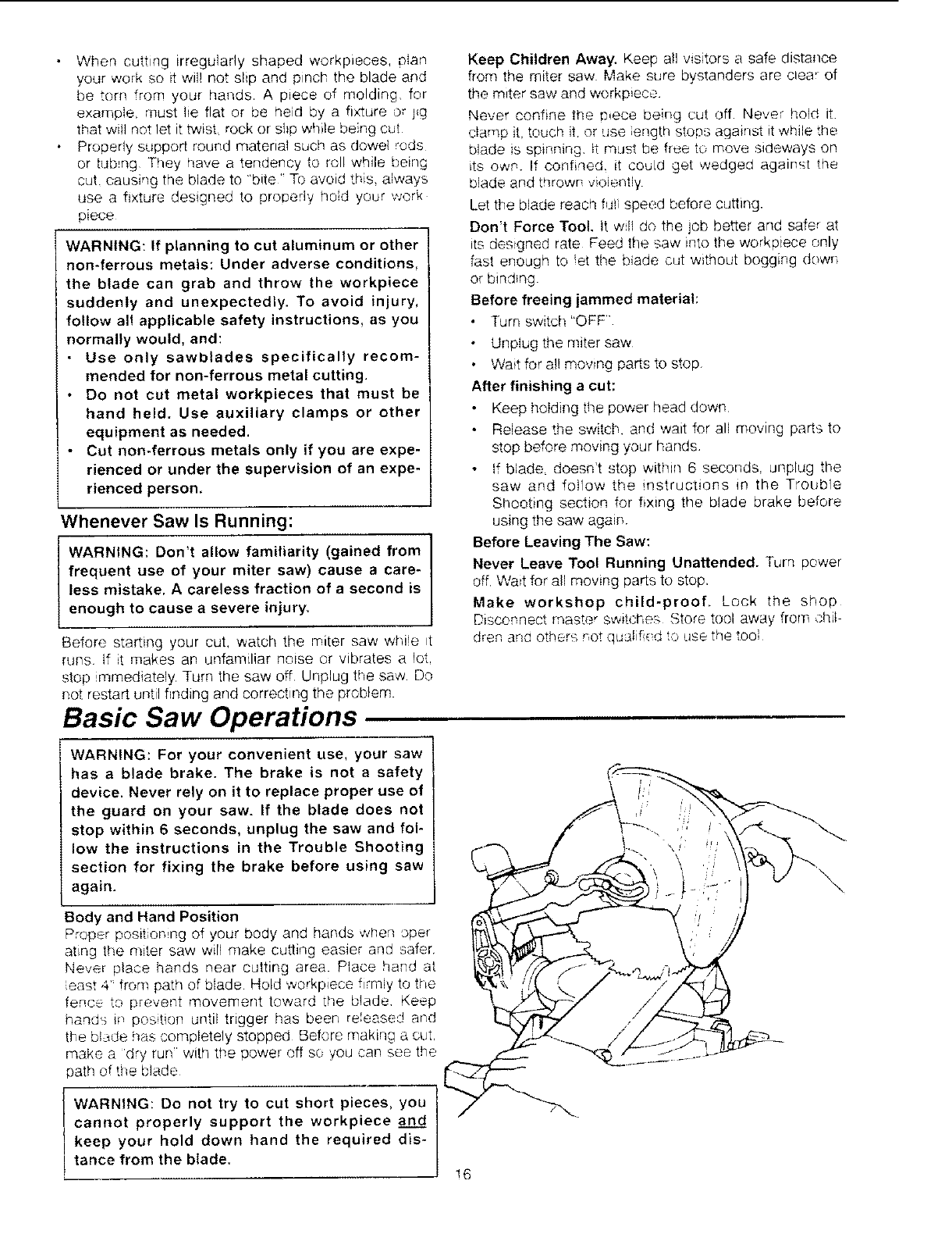
Body and Hand Position
Proper position ng of your body and hands when oper
atLng the miter saw wirl make cutting easier arrd safer.
Never place hands near cutting area Place hand at
east 4 from path of blade Hold werkpiece firmly to the
fence to prevent movement toward the b!ade Keep
hands ff position until trigger has been released and
the bi_,,dehas completely stopped Before making a cut
make a 'dry run' with the power off so you can see the
path of the blade
WARNING: Do not try to cut short pieces, you
cannot properly support the workpiece an_.._dd
keep your hold down hand the required dis-
tance from the blade.
Keep Children Away. Keep all visitors a safe distance
from the miter saw Make sure bystanders are clea_ of
the miter saw and workp_ece
Never confine the #ece being cut off Never hold it
clamp it, touch it,or use ength stops against it while the
blade is spinning it must be free to move sideways on
its own. If confi_led it could get wedged against the
blade and thrown vioiently.
Let the blade reach f@1speed before cutting.
Don't Force Tool. it will do the job better and safer at
itsdesigned rate Feed the saw into the workpiece only
fast enough to et timebiade cut without bogging down
or binding
Before freeing jammed material:
Turn switch "OFF'
Unplug the miter saw
Wait for all moving parts to stop
After finishing acut:
Keep holding the power head down
Release the switch, and wait for all moving parts to
stop before moving your hands
if blade, doesn't stop within 6 seconds, unplug the
saw and follow the instructions in the Trouble
Shooting section for fixing the blade brake before
using the saw again.
Before Leaving The Saw:
Never Leave Tool Running Unattended. Turn power
off. Wait for all moving parts to stop.
Make workshop child-proof, Lock the shop
Disconnect rnaster switche:-_ Store tool away from chit
dren and others not qualif ( d to use the tool
\\
!6
Basic Saw Operations (Continued)
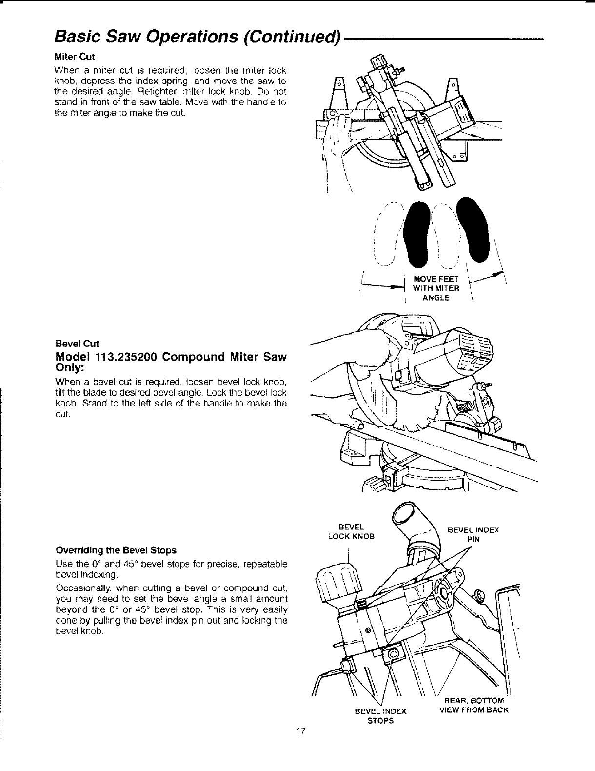
Miter Cut
E
When a miter cut is required, loosen the miter lock
knob, depress the index spring, and move the saw to
the desired angle. Retighten miter lock knob. Do not
stand in front of the saw table. Move with the handle to
the miter angle to make the cut.
i': tj
MOVEFEET
WITH MITER
ANGLE
Bevel Cut
Model 113.235200 Compound Miter Saw
Only:
When a bevel cut is required, loosen bevel lock knob,
tilt the blade to desired bevel angle. Lock the bevel lock
knob. Stand to the left side of the handle to make the
cut.
Overriding the Bevel Stops
Use the 0° and 45 ° bevel stops for precise, repeatable
bevel indexing,
Occasionally, when cutting a bevel or compound cut,
you may need to set the bevel angle a small amount
beyond the 0° or 45 ° bevel stop, This is very easily
done by pulling the bevel index pin out and mockingthe
bevel knob.
BEVEL
LOCK KNOB BEVELINOEX
PiN
\
REAR, BOttOM
VIEW FROM BACK
BEVELINDEX
STOPS
17
Basic Saw Operations
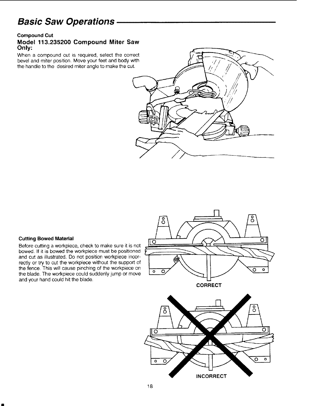
Compound Cut
Model 113.235200 Compound Miter Saw
Only:
When a compound cut is required, select the correct
beveI and miter position, Move your feet and body with
the handle to the desired miter angle to make the cut,
Cutting Bowed Material
Before cutting a workpiece, check to make sure it is not
bowed. If it is bowed the workpiece must be positioned
and cut as illustrated. Do not position workpiece incor-
rectly or try to cut the workpiece without the support of
the fence. This will cause pinching of the workpiece on
the blade. The workpiece could suddenly jump or move
and your hand could hit the blade. CORRECT
!8
INCORRECT
Basic Saw Operations (Continued)
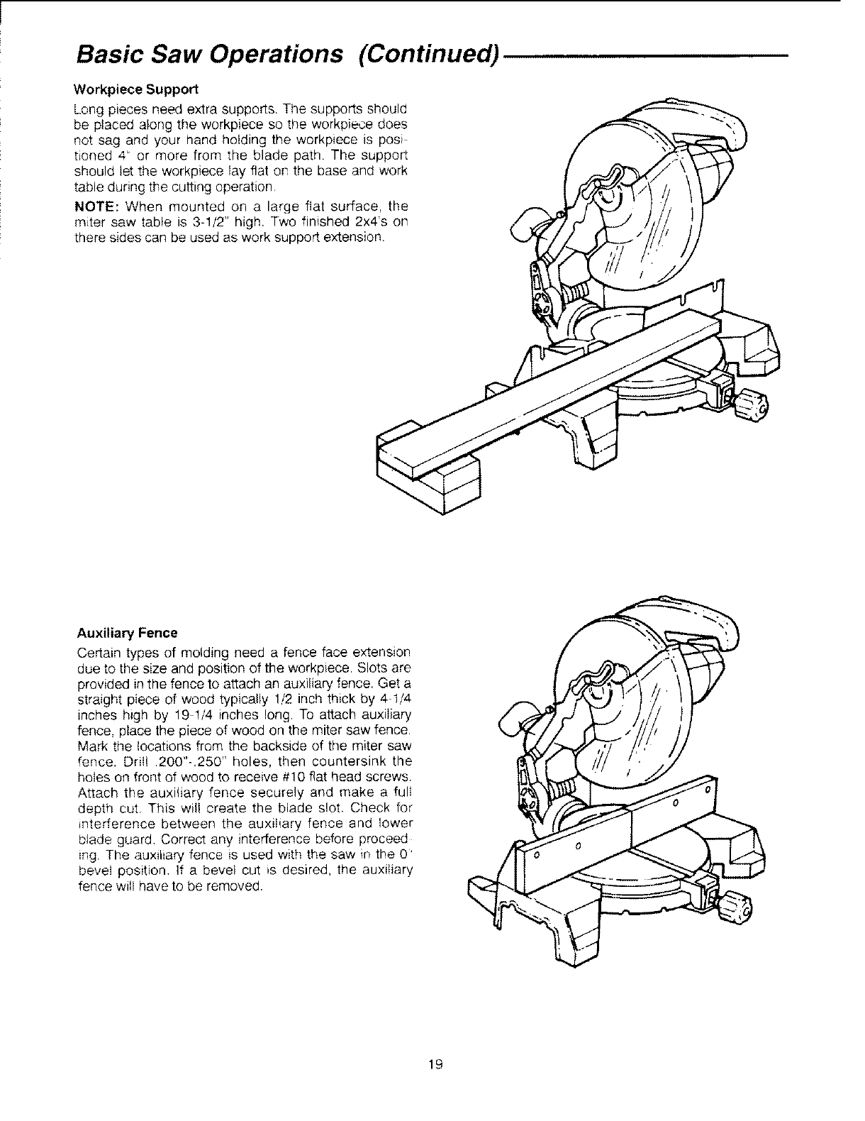
Workpiece Support
Long pieces need extra supports, The supports should
be placed along the workpiece so the workpiece does
not sag and your hand holding the workpiece is posi
tioned 4" or more from the blade path The support
should let the workpiece lay fiat on the base and work
table during the cutting operation
NOTE: When mounted on a large fiat surface, the
miter saw table is 3-1/2" high. Two finished 2x4s on
there sides can be used as work support extension.
Auxiliary Fence
Certain types of molding need a fence face extension
due to the size and position of the workpiece. Slots are
provided in the fence to attach an auxiliary fence. Get a
straight piece of wood typically 1/2 inch thick by 4 t/4
inches high by 19 1/4 inches long To attach auxiliary
fence, place the piece of wood on the miter saw fence,
Mark the locations from the backside of the miter saw
fence. Drill .200"-.250" holes, then countersink the
holes on front of wood to receive #10 flat head screws
Attach the auxiliary fence securely and make a full
depth cut. This will create the blade slot. Check for
interference between the auxiliary fence and lower
blade guard, Correct any interference before proceed
ing. The auxiliary fence is used with the saw in the 0'
bevel position. If a bevel cut is desired, the auxiliary
fence will have to be removed.
19
Basic Saw Operations
MITER SAW
FENCE
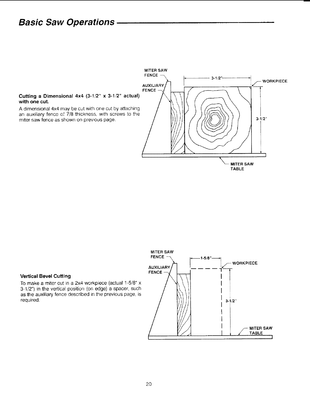
Cutting a Dimensional 4x4 (3-1/2" x 3-1/2" actual)
with one cut.
A dimensional 4x4 may be cut with one cut by attaching
an auxiliary fence o[ 7/8 thickness, with screws to the
miter saw fence as shown on prewous page.
3-1,/2"
_X_ MITER SAW
TABLE
Vertical Bevel Cutting
To make a miter cut in a 2x4 workpiece (actual 1-5/8" x
3-1/2") in the vertical position (on edge) a spacer, such
as the auxiliary fence described in the previous page, _s
required.
MITER SAW
FENCE
_-- WORKPIECE
-T
i
3-1/2"
-MITER SAW
TABLE l
20
Basic Saw Operations (Continued)
Tips for Cutting Compound Miters
Model 113.235200 Only:
A compound miter is a cut requiring both a miter setting
and bevei setting. A compound miter is used for making
frames or boxes that have sloping sides and are wide
at one end and narrow at the opposite end. Compound
miters are "tricky" to make because the miter setting
and bevel setting are directly related to each other
Every time the miter setting is changed the bevel set-
ting must also be adjusted; likewise every adjustment to
bevel requires a corresponding adjustment to miter
Because it may take several tries to obtain the desired
angle it as advisable to make test cuts in a scrap piece
of material.
Cutting Crown Moldings
Plan Ahead so that you are not tempted to reach
across saw blade to steady newly severed workpiece.
Two Methods to Cut Crown Moldings
1. Workpiece standing up, usually cut inverted from
ceiling mounted orientation. Fixturing: Accessory
mounted crown molding jigs which locate workpiece
See recommended accessories. (Table clamp is
helpful). Hand is on fence when the cuts are made.
All cuts are made at 0° bevel setting.
Alternate fix_uring: Auxiliary fence as shown on page
19 plus table clamps.
2. Workpiece lying flat for compound cut (see chart).
Model 113.235200 Only:
Miter and Bevel Settings for Standard
Crown Molding Lying Flat on Miter Saw
Table.
BEVEL
SE'I-FING
33.8 _
33,8 °
33.8"
338
MITER
SETTING
316"
Right
31 65
Left
316
Left
31.6 >
Right
TYPE OF CUT
LEFT SIDE, INSIDE CORNER
1, Position top molding against
fence.
2. Left side is finished piece.
RIGHT SIDE, INSIDE CORNER
1, Position bottom of molding
against fence.
2. Left side is finished piece
LEFT SIDE, OUTSIDE CORNER
1, Position bottom of molding
against fence,
2. Right side is finished piece
RIGHT SIDE, OUTSIDE CORNER
1, Position top of molding
against fence
2. Right side is finished piece.
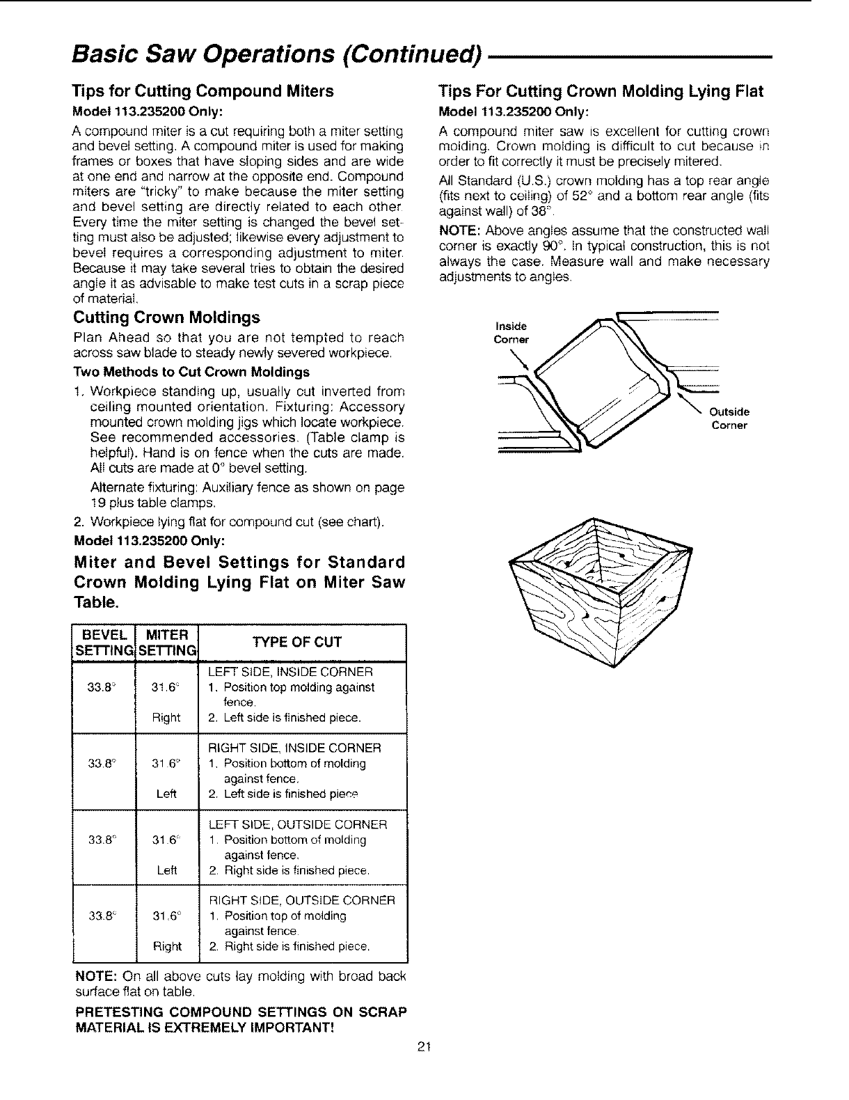
Tips For Cutting Crown Molding Lying Flat
Model 113.235200 Only:
A compound miter saw is excellent for cutting crown
molding. Crown molding is difficult to cut because _n
order to fit correctly it must be precisely mitered.
All Standard (U.S.) crown molding has a top rear angle
(fits next to ceiling) of 52° and a bottom rear angle (fits
against wall) of 38"
NOTE: Above angles assume that the constructed wail
corner is exactly 90°. In typical construction, this is not
always the case. Measure wall and make necessary
adjustments to angles.
Inside
Corner
Outside
Corner
NOTE: On all above cuts lay molding with broad back
surface flat on table.
PRETESTING COMPOUND SETTINGS ON SCRAP
MATERIAL IS EXTREMELY IMPORTANT!
2!
Maintenance and Lubrication
Maintenance
DANGER: Never put lubricants on the blade
while it's spinning.
WARNING: To avoid injury from unexpected
starting or electrical shock, unplug the power
cord before working on the saw.
WARNING: For your safety, this saw is double
insulated. To avoid electrical shock, fire or
injury, use only parts identical to those identi-
fied in the parts list reassemble exactly as orig-
inal assembly to avoid electrical hazards.
Replacing Carbon Brushes
The carbon brushes furnished will last approximately 50
hours of running time or 10,000 on/off cycles. Replace
both carbon brushes when either has less than 1/4"
length of carbon remaining. To inspect or replace first
unpIug the saw. Then remove the motor cap on the end
of the motor by removing 2 screws Remove the lead
wires from the tabs on the brushes, then pull out the
brushes. To reassemble reverse the procedure. Tighten
the screws snugly but do not overtighten.
NOTE: To reinstall the same brushes, first make sure
the brushes go back in the way they came out This wil!
avoid a break in period that reduces performance and
increases wear.
Lower Blade Guard
Do not use the saw without the lower guard. The lower
blade guard is attached to the saw for protection
Should the lower guard become damaged, do not use
the saw until damaged guard has been replaced.
Develop a regular check to make sure the lower guard
is working properly, Clean the lower guard of any dust
or build up with a damp cloth.
CAUTION: Do not use solvents on the guard.
They could make the plastic "cloudy" and brittle..
WARNING: When cleaning lower guard unplug I
the saw from the outlet to avoid unexpected 1
start-up.
Saw Dust
Periodically, sawdust will accumulate under the work
table and base. This could cause difficulty in the move-
ment of the work table when setting up a miter cut.
Frequently blow out or vacuum up the sawdust
WARNING: If blowing sawdust, wear proper
eye protection to keep debris from blowing into
eyes.
Lubrication
AII the motor bearings in this tool are lubricated with a
sufficient amount of high grade lubricant for the life of
the unit under normal operating conditions, therefore,
no further lubrication is required. (See below.)
Infrequent Lubrication as Required:
!. Lubrication of arm pivot for flee movement.
a. Apply oil between washer and contact face of
Table/Pivot casting.
b. Apply oil to pivot shaft next to inside surface of
ears on arm casting.
NOTE: Disassembly should be done by an authorized
service technician. Removal of the upper guard and the
stopshaft is necessary before pivot can be disassem-
bled. Pay close attention to the spring-end positions in
the castings...mark with chalk to avoid later confusion.
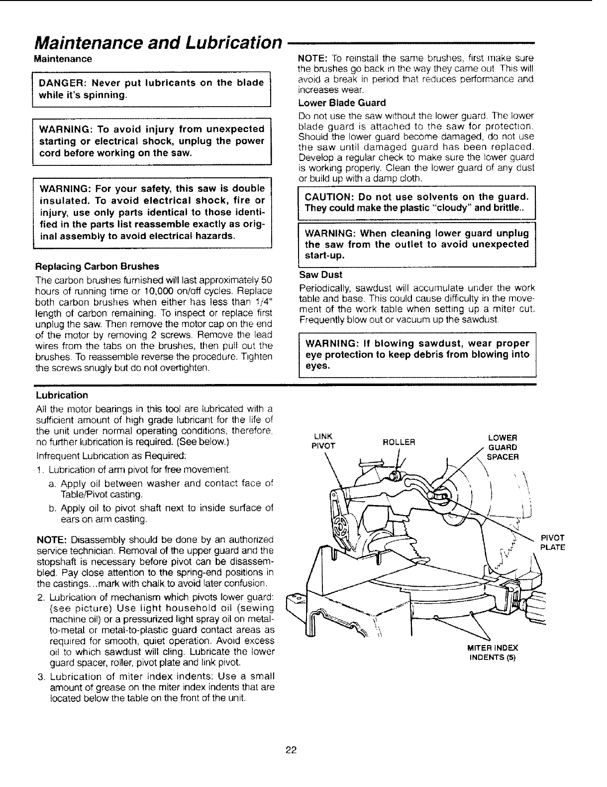
2. Lubrication of mechanism which pivots lower guard:
(see picture) Use light household oil (sewing
machine oiI) or a pressurized light spray oil on metal-
to-metal or metal-to-plastic guard contact areas as
required for smooth, quiet operation. Avoid excess
oil to which sawdust will cling. Lubricate the lower
guard spacer, roller, pivot plate and link pivot.
3. Lubrication of miter index indents: Use a small
amount of grease on the miter index indents that are
located below the table on the front of the unit.
LINK LOWER
PIVOT ROLLER GUARD
SPACER
MITER INDEX
INDENTS (5)
PIVOT
PLATE
22
Sears Recommends the Following Accessories
Recommended Accessories
WARNING: To avoid injury from unsafe acces-
sories, use only accessories shown on the rec-
ommended accessories list in this manual.
Prohibited Accessories
The use of any cutting tool except 10" saw blades
which meet the requirement under recommended
accessories is prohibited, Do not use accessories such
as shaper cutters or dado sets, Ferrous metal (metal
with iron in it) cutting and the use of abrasive wheels
are prohibited, See WARNING and CAUTION notes in
the "Safety Instructions For Basic Saw Operations"
Section, If planning to saw non-ferrous metal see those
WARNING and CAUTION notes in the "Safety
Instructions For Basic Saw Operations" Section.
Leg Sets .............................................................. 9-22244
............................................................................ 9-22246
Carbide-Tipped Blades:
Trim Saw ..................................................... See Catalog
Cut-Off ......................................................... See Catalog
Combination ................................................ See Catalog
Plywood/Particle Board .............................. See Catalog
Non-Carbide Tipped Blades:
Cross Cut/Plywood ..................................... See Catalog
Combination ................................................ See Catalog
Clamp ................................................................ 9-29000
Table Extensions ............................................... 9-29001
Crown Molding Jig ............................................. 9-29002
Dust Bag ............................................................ 9-23467
1-1/4" Sawdust Collector Hose ......................... 9-17866
Basic Blade Requirements
10" Diameter
Blades marked for 5,500 RPM or higher
5/8" Diameter Arbor Hole
23
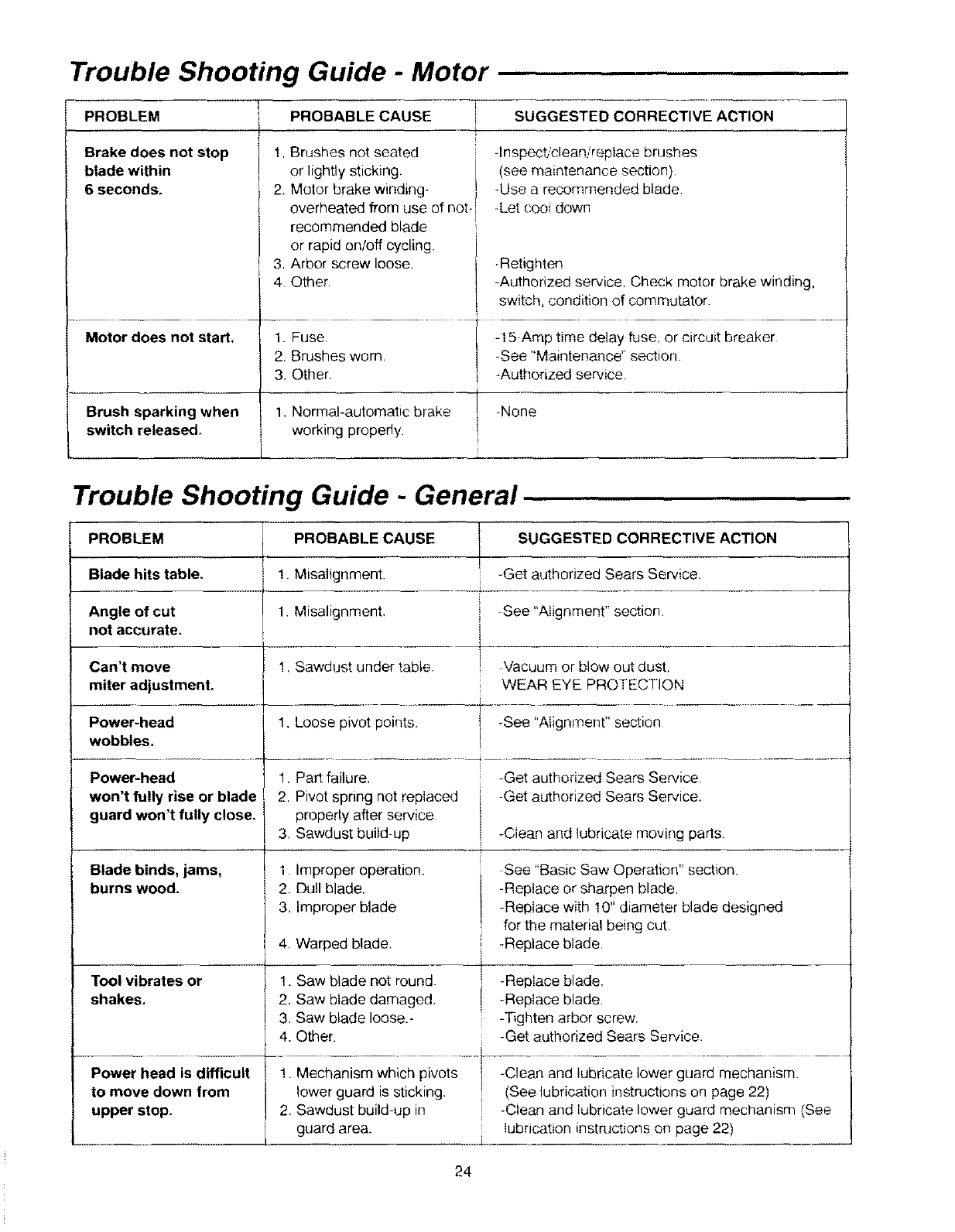
Trouble Shooting Guide -Motor
PROBLEM PROBABLE CAUSE SUGGESTED CORRECTIVE ACTION
Brake does not stop
blade within
6 seconds.
1, Brushes not seated
or lightly sticking.
2. Motor brake winding-
overheated from use of not-
recommended blade
or rapid on/off cycling,
3. Arbor screw loose.
4 Other
-Inspect/clean/replace brushes
(see maintenance section)
-Use a recommended blade
-Let cooi down
-Retighten
Authorized service. Check motor brake winding,
switch, condition of commutator.
Motor does not start.
Brush sparking when
switch released,
1. Fuse.
2. Brushes worn.
3. Other.
1. Normal-automatic brake
working properly
-15 Amp time delay fuse, or circuit breaker
See "Maintenance" section.
_Authodzed service.
None
Trouble Shooting Guide -General .......
PROBLEM
Blade hits table,
Angle of cut
not accurate.
Can't move
miter adiustment,
Power-head
wobbles.
Power-head
won't fully rise or blade
guard won't fully close,
Blade binds, jams,
burns wood.
Tool vibrates or
shakes.
Power head is difficult
to move down from
upper stop.
PROBABLE CAUSE SUGGESTED CORRECTIVE ACTION
1. Misalignment. Get authorized Sears Service.
1. Misalignment, See "Alignment _'section,
1. Sawdust under table Vacuum or blow out dust.
WEAR EYE PROTECTION
1. Loose pivot points. -See "Alignment" section
1. Part failure.
2. Pivot spring not replaced
properly after service
3, Sawdust build up
1 Improper operation.
2. Dull blade,
3, Improper blade
4. Warped blade.
1. Saw blade not round
2, Saw blade damaged.
3. Saw blade loose.-
4. Other.
Get authorized Sears Service
-Get authorized Sears Service.
-Clean and lubricate moving pads.
See "Basic Saw Operation" section.
-Replace or sharpen blade.
-Replace with I0" diameter blade designed
for the material being cut,
-Replace blade.
-Replace blade,
-Replace blade.
-]hghten arbor screw.
-Get authorized Sears Service.
!. Mechanism which pivots -Clean and lubricate lower guard mechanism.
lower guard is sticking, (See lubrication instructions on page 22)
2. Sawdust build up in -Clean and lubricate lower guard mechanism (See
guard area. lubrication instructions on page 22)
24
WHITE
FIELD WINDING BLACK
WIDE BLADE WIRE
NUT BRUSH#1
POWER CORD
BLACK
#2
3 N.O.
SPDT SWITCH
BLACK
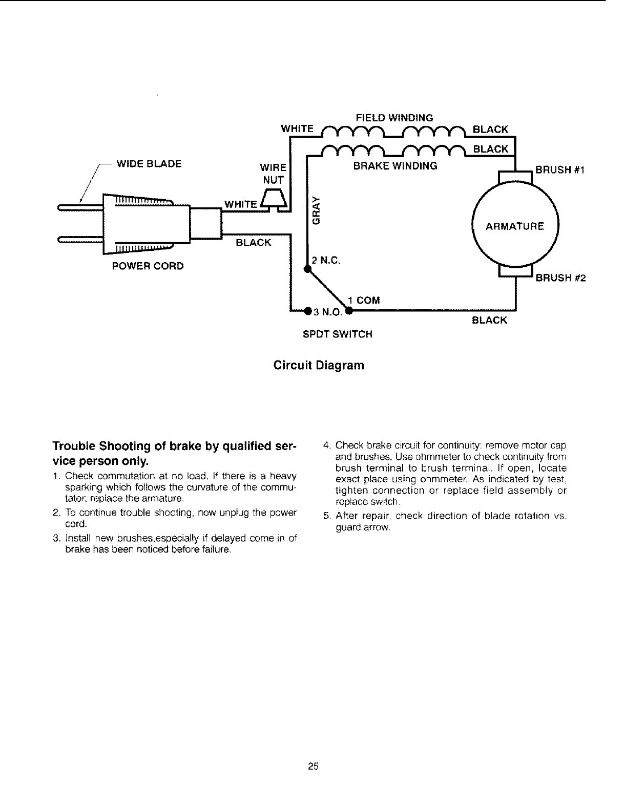
Circuit Diagram
Trouble Shooting of brake by qualified ser-
vice person only.
I. Check commutation at no load. If there is a heavy
sparking which foliows the curvature of the commu-
tator: replace the armature.
2. To continue trouble shooting, now unplug the power
cord.
3. Install new brushes,especially if delayed come-in of
brake has been noticed before failure.
4. Check brake circuit for continuity: remove motor cap
and brushes. Use ohmmeter to check continuity from
brush terminal to brush terminal. If open, locate
exact place using ohmmeter. As indicated by test,
tighten connection or replace field assembly or
replace switch.
5. After repair check direction of blade rotation vs.
guard arrow.
25
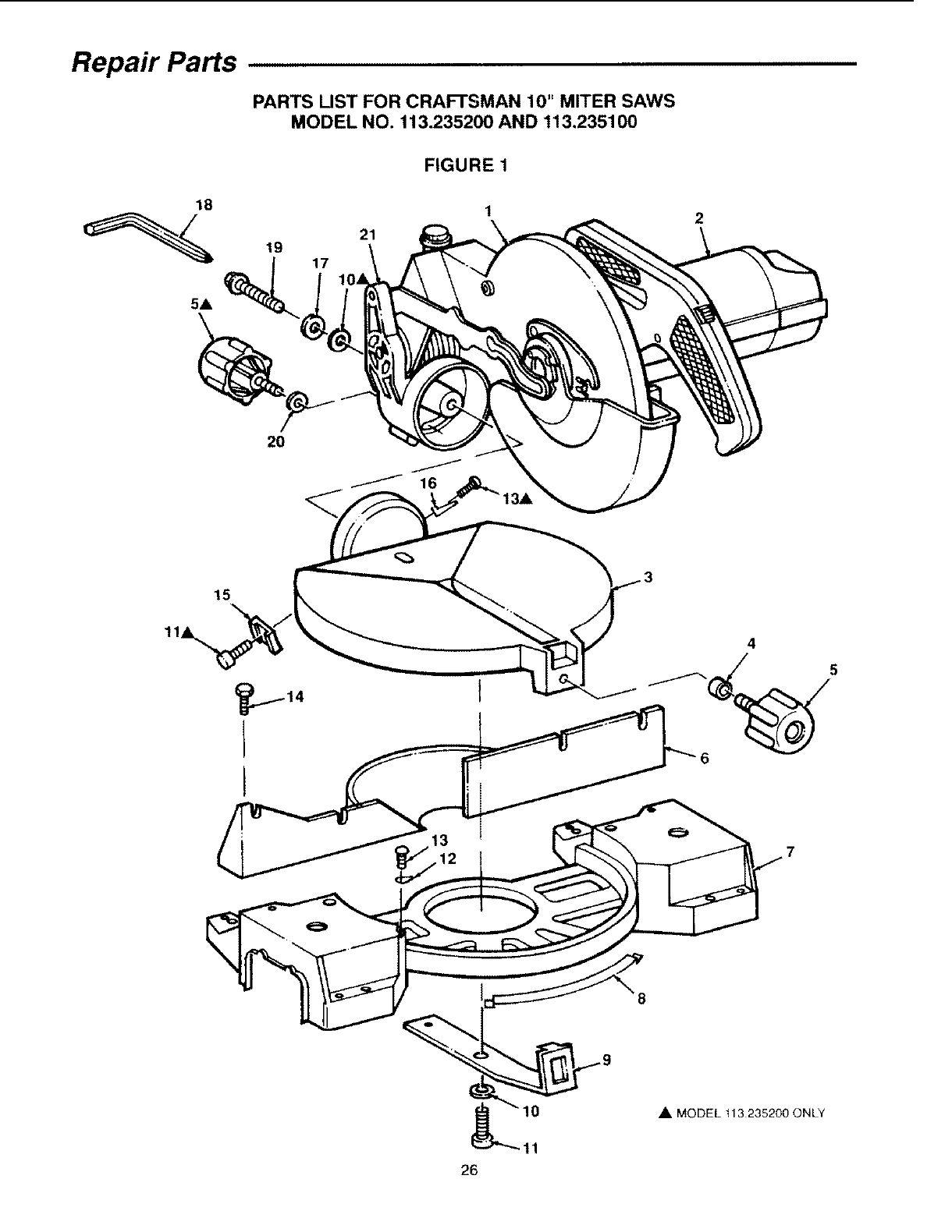
Repair Parts
PARTS UST FOR CRAFTSMAN 10" MITER SAWS
MODEL NO. 113.235200 AND 113,235100
FIGURE 1
18
5A
21
19
2
2O
15
4
6
• MODEL tl 3235200 ONLY
-11
26
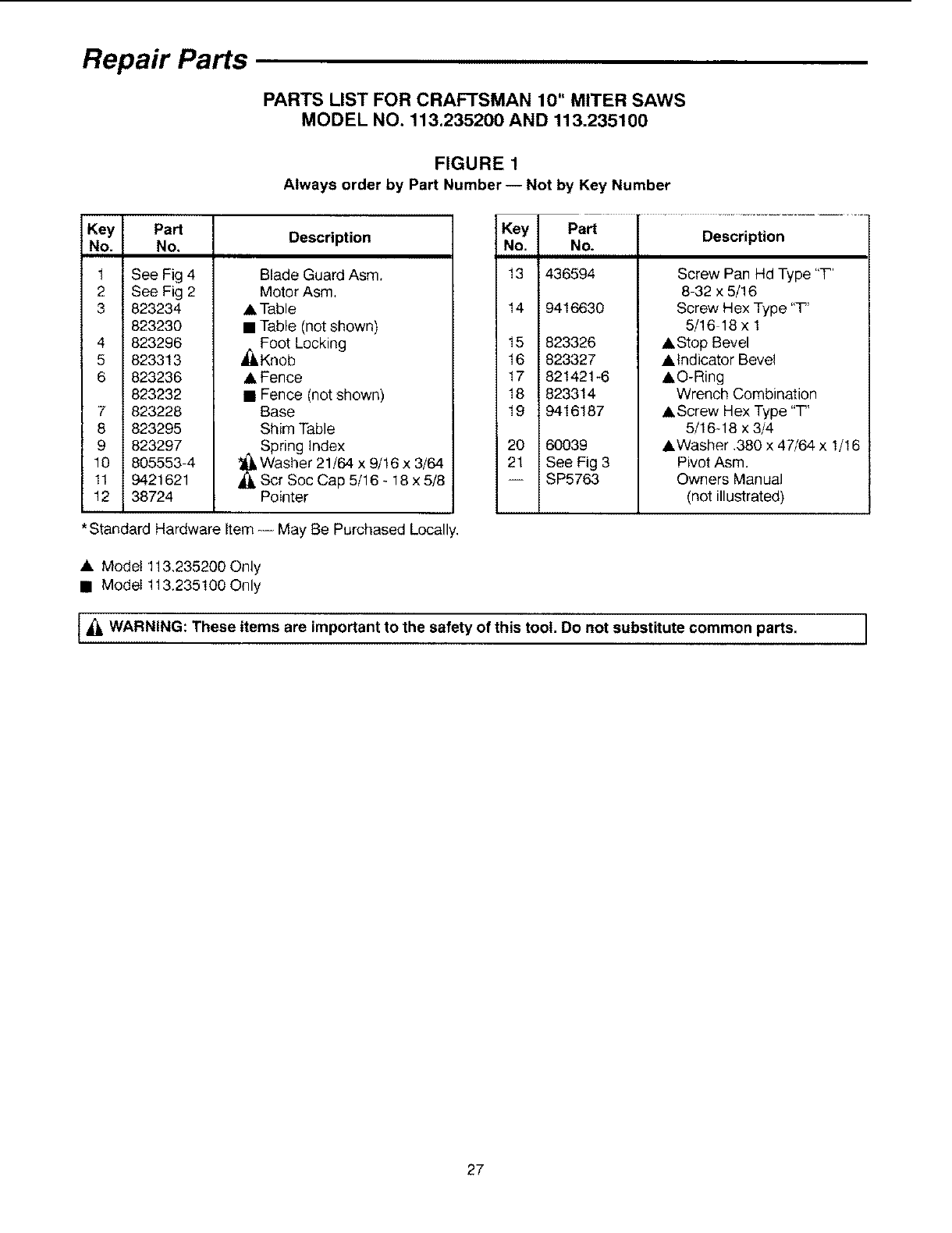
Repair Parts
PARTS LIST FOR CRAFTSMAN 10" MITER SAWS
MODEL NO. 113.235200 AND 113.235100
FIGURE 1
Always order by Part Number-- Not by Key Number
Key
No.
1
2
3
4
5
6
7
8
9
10
11
12
Part
No,
See Fig 4
See Fig 2
823234
823230
823296
823313
823236
823232
823228
823295
823297
805553 4
9421621
38724
Description
Blade Guard Asm.
Motor Asm.
A Table
• Table (not shown)
j_, Foot Locking
Knob
•Fence
• Fence (not shown)
Base
Shim Table
Spring Index
Washer 21/64 x 9/!6 x 3/64
Scr Soc Cap 5/16 - 18 x 5/8
Pointer
Key Part
No. No.
13 1436594
14
823326
823327
821421-6
823314
9416187
20 60039
21 i SeeFig3
-- iSP5763
15
16
17
18
19
Description
Screw Pan Hd Type "T'
8-32 x 5/16
Screw Hex Type "T'
5/16 18 x 1
• Stop Bevel
• indicator Bevel
&O-Ring
Wrench Combination
• Screw Hex Type "T'
5/16q 8 x 3/4
• Washer .380 x 47/64 x 1/16
Pivot Asm.
Owners Manual
(not illustrated)
*Standard Hardware Item-= May Be Purchased Locally,
• Model 113,235200 Only
• Model 113.235100 Only
t_ WARNING: These items are important to the safety of this tool. Do not substitute common parts. I
27
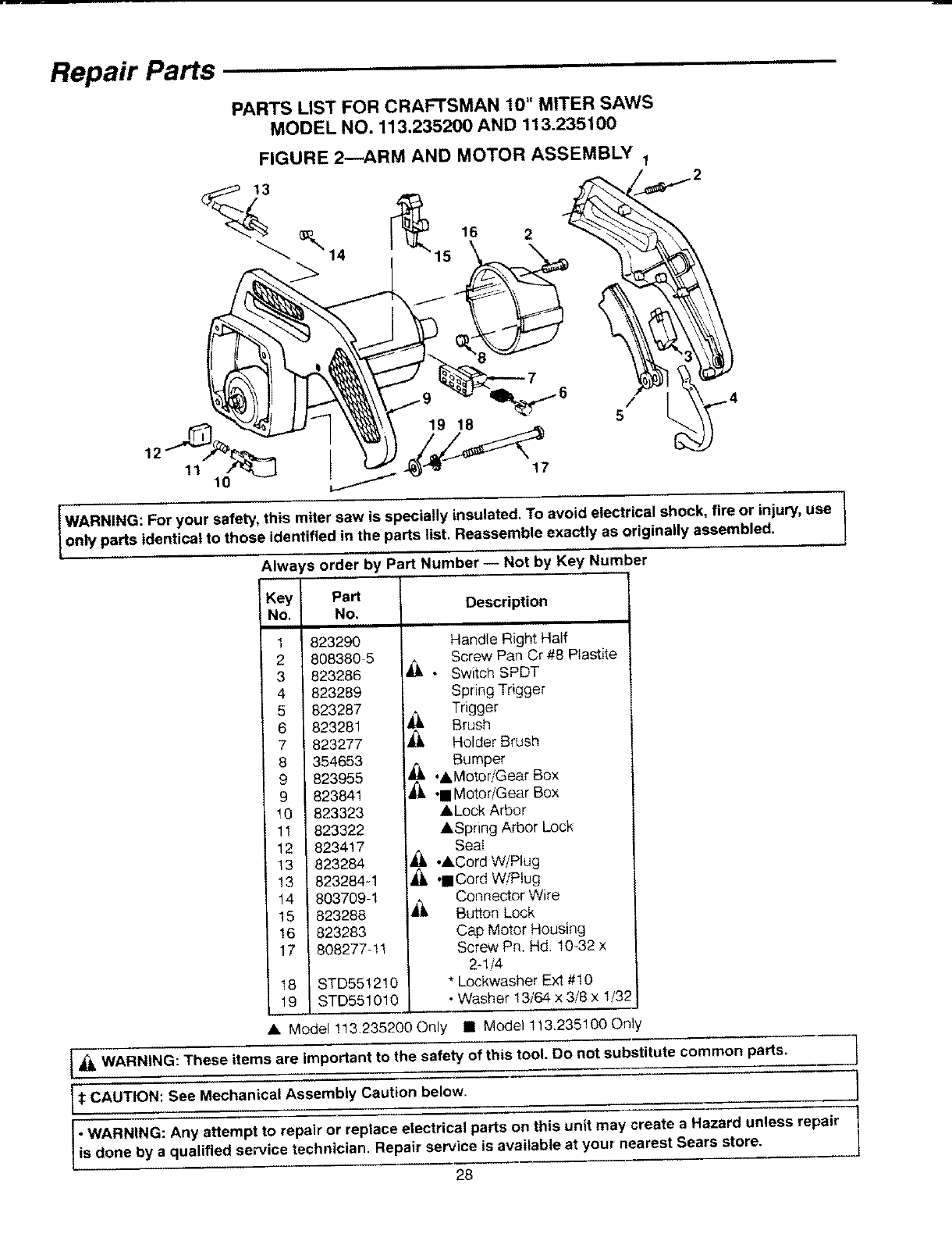
Repair Parts
PARTS LIST FOR CRAFTSMAN 10" MITER SAWS
MODEL NO. 113.235200 AND 113.235100
11
FIGURE 2--ARM AND MOTOR ASSEMBLY T
16 2
15
lO
19 18
/_4
t?
IWARNING: For your safety, this miter saw is specially insulated. To avoid electrical shock, fire or injury, use
only parts identical to those ident!.fied in the parts list, Reassemble exactly as originally assembled.
Always order by Part Number-- Not by Key Number
Key PaN i
No. No.
1 823290
808380 5
823286
4 823289
5 823287
6 823281
7 823277
8 354653
_ 823955
823841
10 823323
11 823322
12 823417
13 823284
13 823284-1
14 803709 1
15 823288
16 823283
17 808277-!1
t8 STD551210
19 STD551010
Description
Handle Right Half
Screw Pan Cr #8 Plastite
• Switch SPDT
Spring Trigger
Trigger
Brush
_, Holder Brush
Bumper
,AMotor/Gear Box
_°• Motor/Gear Box
ALock Arbor
ASpring Arbor Lock
SeaI
_k ,ACord W/Plug
••Cord WfPtug
Connector Wire
_k Button Lock
Cap Motor Housing
Screw Pn, Hd, 10-32 x
2-1/4
• Lockwasher Ext #10
• Washer 13/64 x 3/8 x 1/32
• Model 113.235200 Only • Model 113.235100 Only
1& WARNING: These items are important to the safety of this tool. 13onot substitute common parts. ]
l":_CAUTION: See Mechanical Assembly Caution below. I
•WARNING: Any attempt to repair or replace electrical parts on this unit may create a Hazard unless repair 1
[is done by a qua fled service technician. Repair service is avai able at your nearest Sears store. I
28
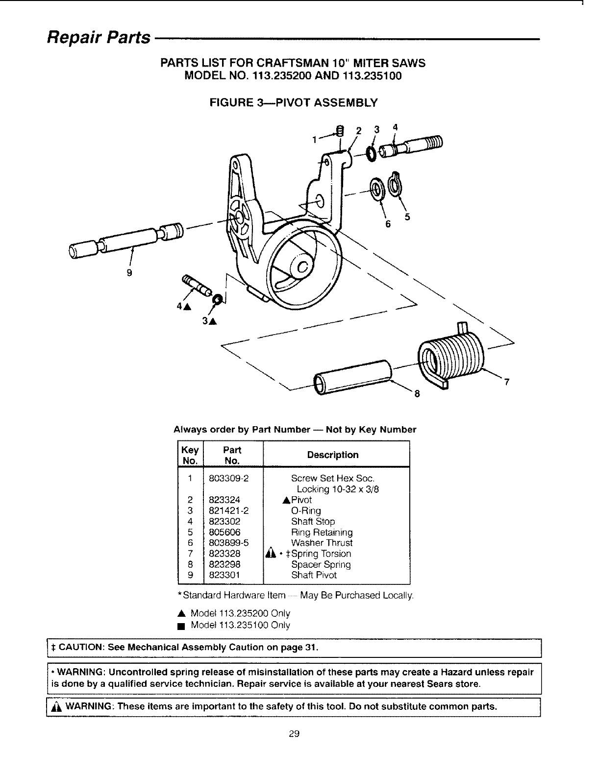
Repair Parts
PARTS LIST FOR CRAFTSMAN 10" MITER SAWS
MODEL NO. 113.235200 AND 113.235100
FIGURE 3--PIVOT ASSEMBLY
2 3 4
5
6
7
Always order by Part Number -- Not by Key Number
Key Part
No. No.
1803309-2
2
3
4
5
6
7
8
9
823324
821421-2
823302
805606
803899-5
823328
823298
823301
Description
Screw Set Hex Soc,
Locking 10-32 x 3/8
A Pivot
O-Ring
Shaft Stop
Ring Retaining
Washer Thrust
• :i:Spring Torsion
Spacer Spring
Shaft Pivot
*Standard Hardware Item May Be Purchased Locally.
• Model t13,235200 Only
• Model 113.235100 Only
_:CAUTION: See Mechanical Assembly Caution on page 31. I
•WARNING: Uncontrolled spring release of misinstallation of these parts may create a Hazard unless repair
is done by a qualified service technician. Repair service is available at your nearest Sears store.
WARNING: These items are important to the safety of this tool. Do not substitute common parts. ]
J
29
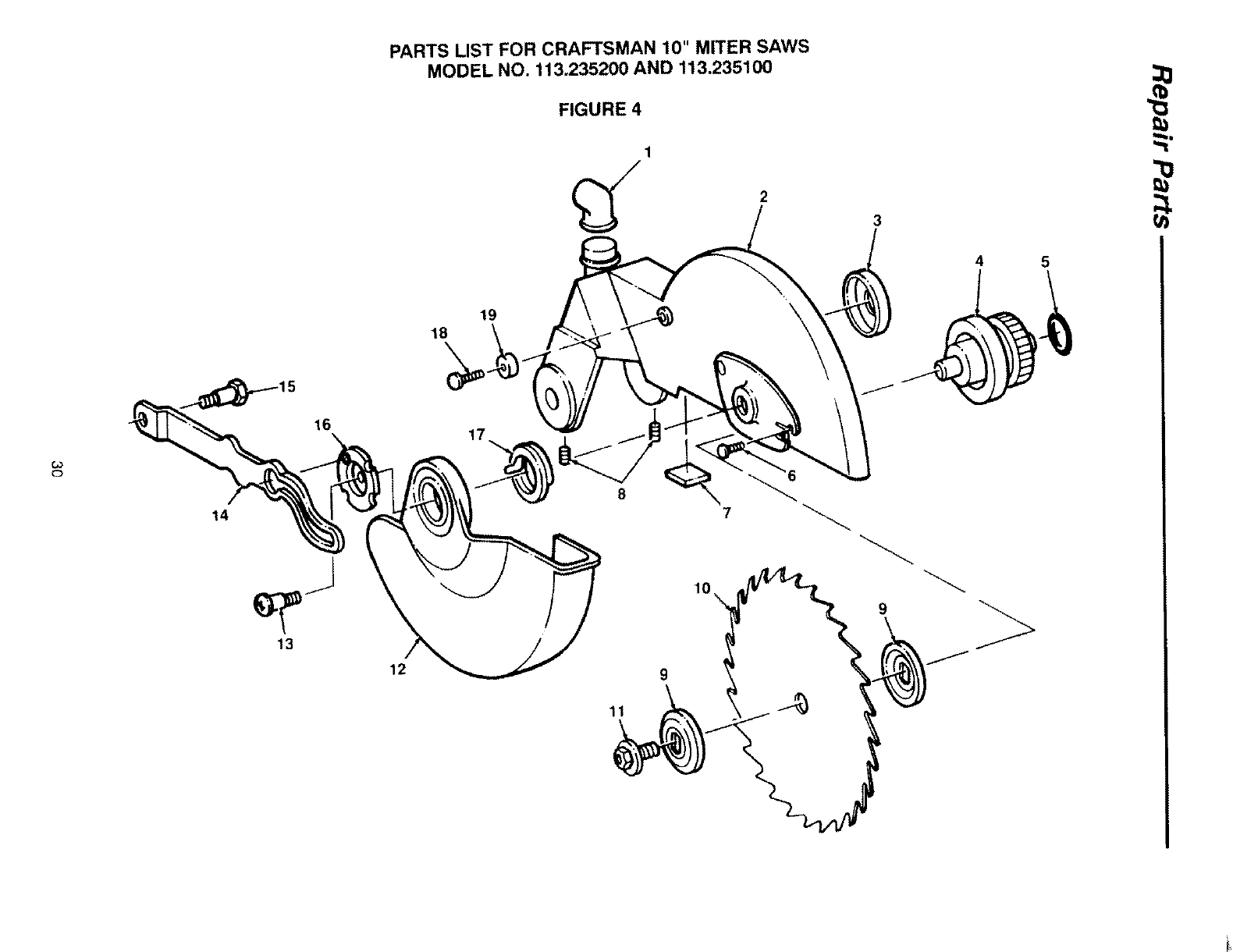
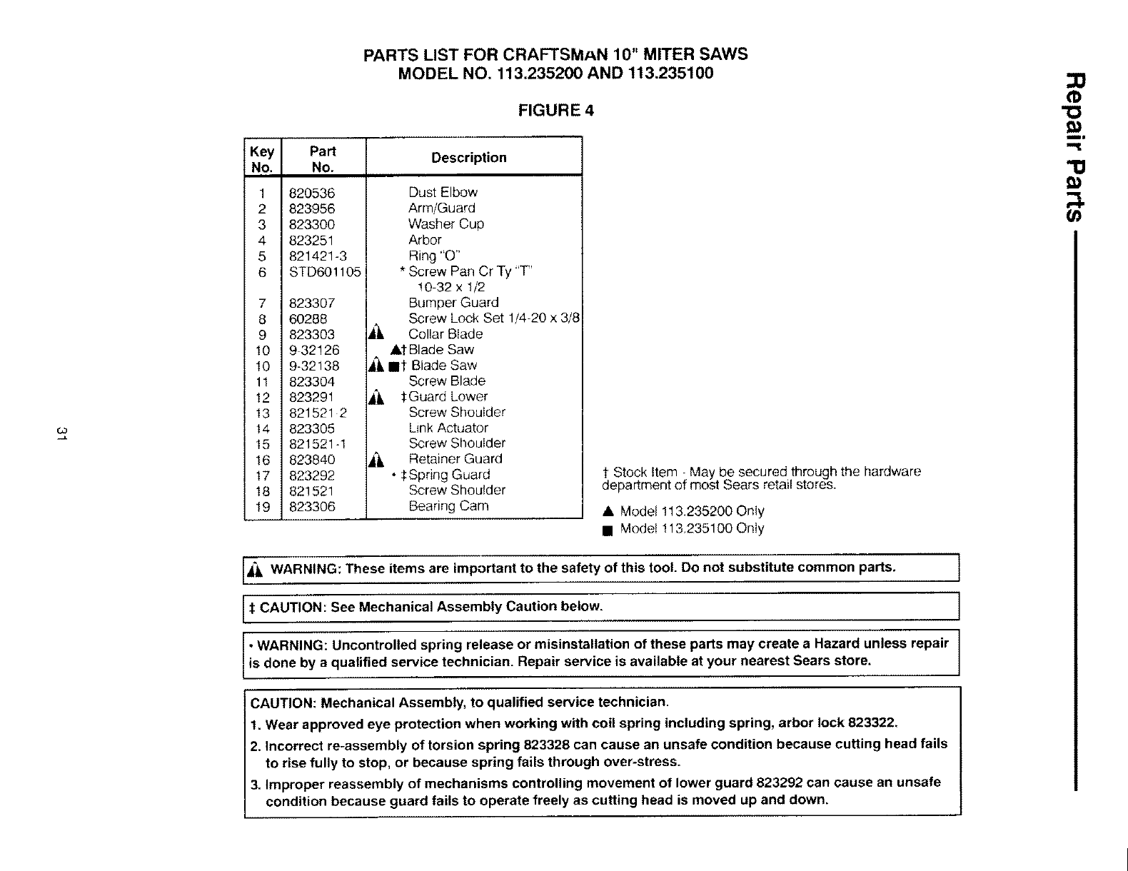
PARTS LIST FOR CRAFTSMAN 10" MITER SAWS
MODEL NO. 113.235200 AND 113.235100
FIGURE 4 "_,
1
3
4 5
o
14
13
16
19
18
17
12
8
10
9
\
9
11
Key
No.
PARTS LIST FOR CRAFTSMAN 10" MITER SAWS
MODEL NO. 113.235200 AND 113.235100
FIGURE 4
1
2
3
4
5
6
Part
No,
820536
823956
823300
823251
821421-3
STD601105i
7 823307
8 60288
9 823303
10 9 32126
10 9-32138
11 823304
12 823291
13 821521 2
14 823305
15 821521q
16 823840
17 823292
18 821521
19 823306
Description
Dust Elbow
Arm/Guard
Washer Cup
Arbor
Ring "O"
* Screw Pan Cr Ty "T"
10 32 x 1/2
Bumper Guard
Screw Lock Set 1/4-20 x 3/8
Collar Blade
AI Blade Saw
4"kmt Blade Saw
Screw Blade
Jk 1.Guard Lower
Screw Shoulder
Link Actuator
Screw Shoulder
_, Retainer Guard
• SSpring Guard
Screw Shoulder
Bearing Cam
dt Stock Item ; May be secured through the hardware
epartment or most Sears retail stores.
• Model 113.235200 Only
• Model 113.235100 Only
"10
IA*k WARNING: These items are important to the safety of this tool. Do not substitute common parts. )
)_t CAUTION: See Mechanical Assembly Caution below.
•WARNING: Uncontrolled spring release or misinstallation of these parts may create a Hazard unless repair
is done by a qualified service technician. Repair service is available at your nearest Sears store.
CAUTION: Mechanical Assembly, to qualified service technician.
t. Wear approved eye protection when working with coil spring including spring, arbor lock 823322,
2. Incorrect re-assembly of torsion spring 823328 can cause an unsafe condition because cutting head fails
to rise fully to stop, or because spring fails through over-stress.
3. Improper reassembly of mechanisms controlling movement of lower guard 823292 can cause an unsafe
condition because guard fails to operate freely as cutting head is moved up and down,
f/
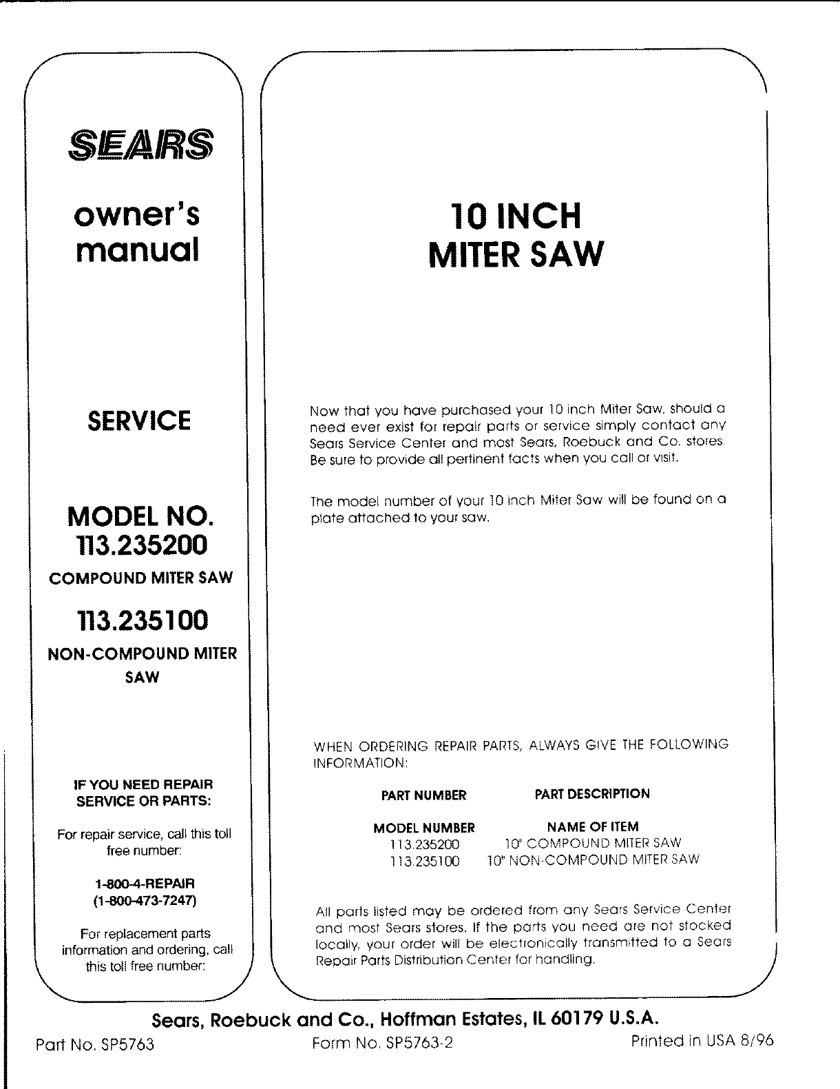
SE/AIR$
owner's
manual
SERVICE
MODEL NO.
113.235200
COMPOUND MITER SAW
113.235100
NON-COMPOUND MITER
SAW
IF YOU NEED REPAIR
SERVICE OR PARTS:
For repair service, call this toll
free number:
1-800-4-REPAIR
(1-800-473-7247)
For replacement parts
information and ordering, call
this tolI free number:
10 INCH
MITERSAW
Now that you have purchased your !0 inch Miter Saw, should a
need ever exist for repair parts or service simply contact any
Sears Service Center and most Sears, Roebuck and Co, stores
Be sure to provide all pertinent facts when you call of visit,
The model number of your 10 inch Miter Saw will be found on a
plate attached to your saw.
WHEN ORDERING REPAIR PARTS, ALWAYS GIVE THE FOLLOWING
INFORMATION:
PARTNUMBER PARTDESCRIPTION
MODEL NUMBER NAME OF ITEM
! 13,235200 10' COMPOUND MITER SAW
113,235100 10I' NON-COMPOUND MITER SAW
All parts listed may be ordered from any Sears Service Center
and most Sears stores, If the parts you need are not stocked
locally, your order wilI be eIectronically transmitted to a Sears /
Repair Parts Distribution Center for handling. 1;
Sears, Roebuck and Co., Hoffman Estates, IL 60179 U.S.A.
Part No, SP5763 Form No, SP5763-2 Printed in USA 8/96
