Craftsman 113235140 User Manual 12 INCH COMPOUND MITER SAW Manuals And Guides L0808266
CRAFTSMAN Miter Saw Manual L0808266 CRAFTSMAN Miter Saw Owner's Manual, CRAFTSMAN Miter Saw installation guides
User Manual: Craftsman 113235140 113235140 CRAFTSMAN 12 INCH COMPOUND MITER SAW - Manuals and Guides View the owners manual for your CRAFTSMAN 12 INCH COMPOUND MITER SAW #113235140. Home:Tool Parts:Craftsman Parts:Craftsman 12 INCH COMPOUND MITER SAW Manual
Open the PDF directly: View PDF ![]() .
.
Page Count: 36
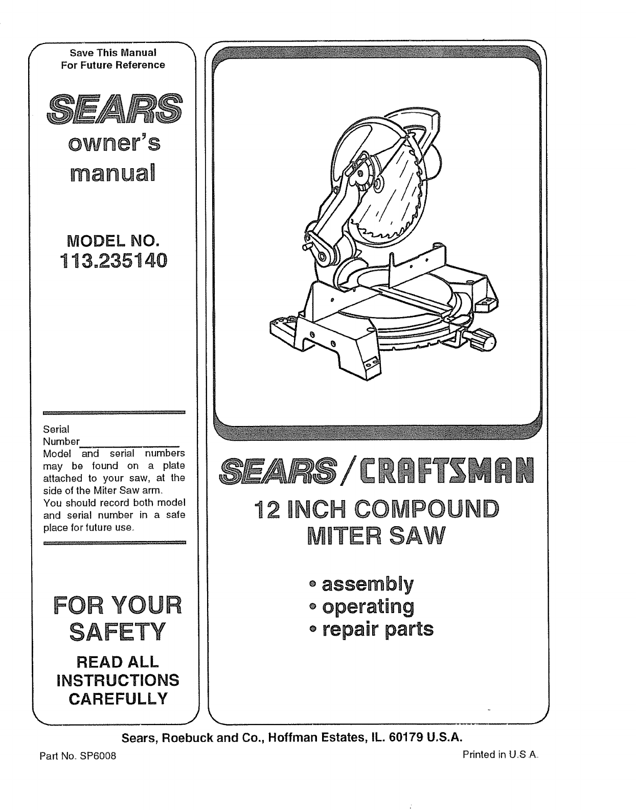
FSave This Manual
For Future Reference
owner's
manua
NODEL NO.
t 13.235140
Serial
Number
Modal and serial numbers
may be found on a plata
attached to your saw, at the
side of the Miter Saw arm,,
You should record both model
and seria! number in a safe
place for future use_
FOR YOUF
READ ALL
INSTRUCTIONS
CAREFULLY
Part No, SP6008
oassembny
o operating
o repair parts
J
Sears, Roebuck and Co., Hoffman Estates, IL. 60179 U.S.A.
Printed in U.S A.
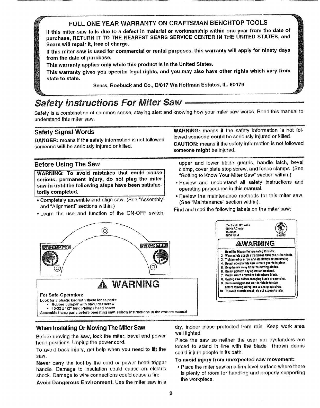
FULL ONE YEAR WARRANTY ON CRAFTSMAN BENCHTOP TOOLS
If this miter saw fails due to a defect in material or' workmanship within one year' from the date of
purchase, RETURN IT TO THE NEAREST SEARS SERVICE CENTER IN THE UNITED STATES, and
Sears will repair it, free of charge°
If this miter' saw is used for' commercial or rental purposes, this warranty will apply for ninety days
from the date of purchase.
This warranty applies only while this product is in the United States.
This warranty gives you specific legal rights, and you may also have other rights which vary from
state to state.
Sears, Roebuck and Co,, D/817 Wa Hoffman Estates, IL. 60179
Safety instructions For Miter Saw ................................
Safety is a combination of common sense, staying alert and knowing how your miter saw works. Read this manual to
understand this miter' saw
Safety Signal Words
DANGER: means if the safety information is not followed
someone will be seriously injured or killed.
....i 1,1,,11 ,,,]1,_1,1 i i ,,i,,,,111¸ ,, i,,,,,,,,,,,11,_
Before Using The Saw
L_.....
WARNING: To avoid mistakes that could cause
serious, permanent injury, do not plug the miter
saw in until the following steps have been satisfac-
torily completed.
° Completely assemble and align saw. (See "Assembly"
and "Alignment" sections within _)
. Learn the use and function of the ON-OFF switch,
WARNING: means if the safebJ information is not fol-
lowed someone could be seriously injured or killed
CAUTION: means if the safety information is not followed
someone might be injured,.
......... , :,:: :::. .... , ,....
upper' and lower blade guards, handle latch, bevel
clamp, cover' plate stop screw, and fence clamps. (See
"Getting to Know Your Miter Saw" section within)
° Review and understand all safety instructions and
operating procedures in this manual
° Review the maintenance methods for this miter saw.
(See "Maintenance" section within).
Find and read the following labels on the miter saw:
WARNING
For Safe Operation:
Look for a plastic bag with these loose pads:
• Rubber bumper with shouldsrscrsw
• 10-32 x 1/2" long Phillips head screw
Assemble these parts before operating saw,. Follow instructions in the owners manual
60HzACon_f
15 m"nps
4O00 RPM E_S
, WARNING
1. RoadtheManna|baforaudnBthissaw.
2, Wear=sfdy gagglasthatn_aatAHSIT-87.tSlandsrd=,.
3_ TlltMsnarborscrewandall utazTIplbeforesawinliI.
4. _o natoparatathissawwithoutousrdstflplace
[i, K_ophandsawaytmx:rlt_llmovlngbtados,
6_ Dosatponotrnsay opsral[anfmohatid.
7,, Donotroacharn_r_ or behindsawblade,,
9, {lnPlsOmawbot_tod_al_gtagbladoorservicing..
9.. Rolna=n_tEar al_ waltlot bladatoIdop
botsramay]figwo_plase_r €._angtngsot-,p.
10. Toavoidhill€trioshack,doaut axp0saIs rain_
When Installing Or Moving The Miter Saw
Before moving the saw, lock the miter, bevel and power
head positions.. Unplug the power cord.
To avoid back injury, get help when you need to lift the
saw.
Never carry the tool by the cord or power head trigger
handle. Damage to insulation could cause an electric
shock. Damage to wire connections could cause a fire.
Avoid Dangerous Environment° Use the miter-saw in a
dry, indoor place protected from rain.. Keep work area
well lighted
Place the saw so neither the user nor bystanders are
forced to stand in line with the blade. Thrown debris
could injure people in its path.
To avoid injury from unexpected saw movement:
•Place the miter saw on a firm level surface where there
is plenty of room for handling and properly supporting
the workplace.
2
° Supportthemitersawsothetableis levelandthesaw
doesnotrock,.
•Bolt or clamp the saw to its support.
o Never Stand On Tool. Serious injury could occur if the
tool tips or you accidentally hit the cutting tool.. Do not
store anything above or near the tool where anyone
might stand on the tool to reach them.
To avoid injury or death from electrical shock:
° Make sure your fingers do not touch the plug's metal
prongs when plugging or unplugging the miter saw..
Before Each Use
Inspect your miter saw.
Disconnect The Miter Saw,, To avoid injury from acci-
dental starting, unplug the saw, before changing the
setup, changing the blade or adjusting anything.
Compare the direction of rotation arrow on the guard to
the direction arrow on the blade.. The blade teeth should
the arm all the way down, then let it rise up until it
stops by itself.. Check the lower guard to see if it closed
fully.. If it did not, follow the instructions in the Trouble
Shooting section,.
° Other conditions that may affect the way the miter saw
works
If any part of this miter saw is missing, bent, or broken in
always point downward at the front of the saw
Tighten the arbor screw.
Tighten the cover plate stop screw.
Check For Damaged Parts. Check for:
° Proper Alignment of moving pads,
°Damaged electric cords,
. Binding of moving parts,
° Broken parts,
°Stable mounting,
any way, or any electrical parts don't work, turn the saw
off and unplug it. Replace damaged, missing, or failed
parts before using the saw again
Keep Guards In Place, in working order, and in proper
adjustment..
Maintain Tools With Care, Keep the miter saw clean for
best and safest performance. Follow instructions for lubri-
cating_ DON'T put lubricants on the blade while it's spin-
ning,.
Remove Adjusting Keys And Wrenches from tool
• Function of arm return spring and lower guard: Push before turning it on.
To Avoid Injury From Jams, Slips Or Thrown
Pieces
•Use Only Recommended Accessories. (See "Acces-
sory" section within) Consult this Owner's manual for
recommended accessories. Follow the instructions
that come with the accessoriesr The use of improper
accessories may cause risk of injury to persons..
°Choose the right 12-inch diameter blade for the mate-
rial and the type of cutting you plan to don
. Make sure the blade is sharp, undamaged and prop-
erly aligned.. With the saw unplugged, push the power-
head all the way down Hand spin the blade and check
for clearance, Tilt the power-head to 45 degree bevel
and repeat the check. If the blade hits anything, make
,, ,,,_rl_ H,'"i'll ....... _1_'_"±'I I
the adjustments shown in the Maintaining Maximum
Cutting Capacity section.
° Make sure the blade and arbor collars are clean.
°Make sure the collars' recessed sides are facing the
blade..
•Using the 1/4" hex end of combination wrench (sup-
plied) or a 1/2-inch box end wrench, make sure the
arbor cap screw is firmly hand tightened
°Make sure all clamps and locks are tight and there is
no excessive play in any parts.
oKeep Work Area Clean. Cluttered areas and benches
invite accidents. Floor must not be slippery_
To avoid burns or other fire damage, never use the saw
near flammable liquids, vapors or gases..
Plan Ahead To Protect Your Eyes, Hands,
Face, Ears.
Know Your Miter Saw. Read and understand the
owner's manual and labels affixed to the tool Learn its
applications and limitations as well as the specific poten-
tial hazards peculiar to this tool,
To avoid injury from accidental contact with moving parts,
don't do layout, assembly, or setup work on the miter saw
while any parts are moving,
Avoid Accidental Starting. Make sure switch is "OFF"
before plugging miter saw into a power outlet
Plan your work,
Use The Right Tool. Don't force tool or attachment to do
ajob it was not designed to do.. Use a different tool for
any workpiece that can't be held in a solidly braced, fixed
position.
............ ;:.... ,,,,, .............
CAUTION: This machine is not designed for cutting
ferrous metals (steel, iron and iron based metals).
Use this miter saw to cut only wood, wood like
products or soft metals like aluminum. Other mate-
rial may shatter, bind on the blade, or create other
dangers.
CAUTION: When cutting any metals, sparks or hot
fragments could cause a fire. To avoid this, discon-
nect any dust collecting bag or hose from the miter
saw, and remove all traces of wood dust from
inside dust traps in the miter saw.
Safety Instructions fen"Miter Saws (continued) ....................................
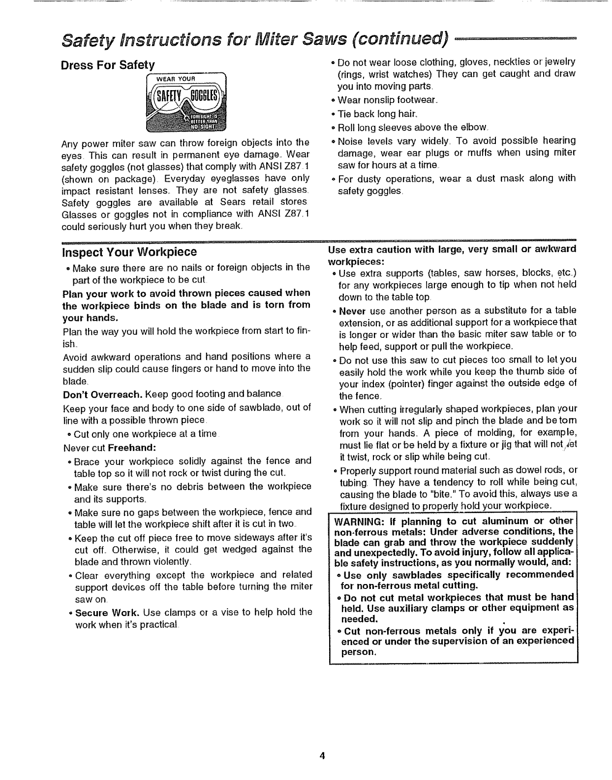
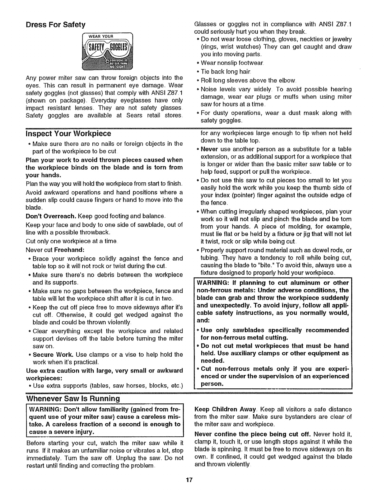
Dress For Safety
WEAR YOUR
Any power miter saw can throw foreign objects into the
eyes. This can result in permanent eye damage.. Wear
safety goggles (not glasses) that comply with ANSI Z87 1
(shown on package). Everyday eyeglasses have only
impact resistant lenses.. They are not safety glasses
Safety goggles are available at Sears retail stores
Glasses or goggles not in compliance with ANSI Z87_1
could seriously hurt you when they break=
oDo not wear loose clothing, gloves, neckties or' jewelry
(rings, wrist watches) They can get caught and draw
you into moving parts.
• Wear nonslip footwear.
• Tie back long hair_
• Roll long sleeves above the elbow.
° Noise levels vary widely,. To avoid possible hearing
damage, wear' ear plugs or muffs when using miter
saw for hours at a time.
o For dusty operations, wear a dust mask along with
safety goggles,
Inspect Your Workpiece
• Make sure there are no nails or foreign objects in the
part of the workpiece to be cut
Plan your work to avoid thrown pieces caused when
the workpiece binds on the blade and is torn from
your hands.
Plan the way you will hold the workpiece from start to fin_
ish..
Avoid awkward operations and hand positions where a
sudden slip could cause fingers or hand to move into the
blade.
Don't Overreach. Keep good footing and balance
Keep your face and body to one side of sawblade, out of
line with a possible thrown piece.
• Cut only one workpiece at a time
Never cut Freehand:
° Brace your workpiece solidly against the fence and
table top so it wil! not rock or'twist during the cut.,
°Make sure there's no debris between the workpiece
and its supports.
oMake sure no gaps between the workpiece, fence and
table will let the workpiece shift after' it is cut in two..
° Keep the cut off piece free to move sideways after it's
cut off.. Otherwise, it could get wedged against the
blade and thrown violently_
° Clear everything except the workpiece and related
support devices off the table before turning the miter
saw on.
°Secure Work. Use clamps or a vise to help hold the
work when it's practical
............. ........ ,L ................ ,, ,,, ............. , ........................ , , ...... ,, ,:.............. , ........ _..........
Use extra caution with large, very small or awkward
workpieces:
°Use extra supports (tables, saw horses, blocks, etc.,)
for any workpieces large enough to tip when not held
down to the table top.
°Never use another person as a substitute for a table
extension, or as additional support for a workpiece that
is longer or wider than the basic miter saw table or to
help feed, support or' pull the workpiece.
°Do not use this saw to cut pieces too small to let you
easily hold the work while you keep the thumb side of
your index (pointer) finger against the outside edge of
the fence..
°When cutting irregularly shaped workpieces, plan your'
work so it will not slip and pinch the blade and be tom
from your hands.. A piece of molding, for example,
must tie flat or be held by a fixture or jig that will notj,_et
it twist, rock or slip while being cut..
°Properly support round material such as dowel rods, or
tubing. They have a tendency to roll while being cut,
causing the blade to "bite." To avoid this, always use a
fixture designed to properly hold your' workpiece.
WARNING: If planning to cut aluminum or' other
non-ferrous metals: Under adverse conditions, the
blade can grab and throw the workpiece suddenly
and unexpectedly. To avoid injury, follow all applica-
ble safety instructions, as you normally would, and:
oUse only sawblades specifically recommended
for non-ferrous metal cutting,
o Do not cut metal workpieces that must be hand
held. Use auxiliary clamps or other equipment as
needed.
oCut non-ferrous metals only if you are experi-
enced or under the supervision of an experienced
person,
Whenever Saw is Running
WARNING: Don't allow familiarity (gained from fre-
quent use of your miter saw) cause a careless mis-
take. A careless fraction of a second is enough to
cause a severe injury.
Before starting your cut, watch the miter saw while it
runs. If it makes an unfamiliar noise or vibrates a lot, stop
immediately° Turn the saw off. Unplug the saw Do net
restart until finding and correcting the problem.
Keep Children Away,. Keep all visitors a safe distance
from the miter saw. Make sure bystanders are clear of
the miter saw and workpiece
Never confine the piece being cut off. Never hold it,
clamp it, touch it, or use length stops against it while the
blade is spinning. It must be free to move sideways on its
own. if confined, it could get wedged against the blade
and be thrown violently.
Let the blade reach full speed before cutting. This will
help avoid thrown workpieces
Don't Force Tool. It will do the job better and safer at its
designed rate. Feed the saw into the workpiece only fast
enough to let the blade cut without bogging down or binding..
Before freeing jammed material:
•Turn miter saw "OFF" by releasing trigger switch
°Wait for all moving parts to stop.
°Unplug the miter saw
After finishing acut:
°Keep holding the power head down..
°Release the switch, and wait for all moving parts to
stop before moving your hands or raising power head
°If blade doesn't stop within 6 seconds, unplug the saw
and follow the instructions in the Trouble Shooting sec-
tion for fixing the blade brake before using the saw
again..
Before Leaving The Saw the hole provided in the trigger to prevent unauthorized
Never Leave Tool Running Unattended,Turn power usage., Lock the shop. Disconnect master switches. Store
tool away from children and others not qualified to use
off. Wait for all moving parts to stop., the tool,
Make Workshop Child Proof. Install a padlock through
Glossary of Terms for Woodworking
Arbor
The shaft on which a cutting tool is mounted.
Bevel Cut
An angle cutting operation made through the face of the
workpiece.
Compound Cut
A simultaneous bevel and miter cutting operation.
Crosscut
Acutting operation made across the width of the work-
piece.
Freehand
Doing a cut without holding the workpiece against both
the table and fence. Most workpieces can be held down
with your hand Large or wide pieces should be clamped
to the fence or table.
Gum
A sticky, sap based residue from wood products..
Heel
Misalignment of the blade
Kerr
The amount of material removed by the blade in a
through cut or the slot produced by the blade in a non-
through or partial cut
Miter Cut
An angle cutting operation made across the width of the
workpiece._
Resin
A sticky, sap based substance that has hardened.
Revolutions Per Minute (RPM)
The number of turns completed by a spinning object in
one minute.
Sawblade Path
The area of the workpiece or table top directly in line with
either the travel of the blade or the part of the workpiece
which will be, or has been, cut by the blade
Set
The distance that the tip of the sawblade tooth is bent (or
set) outward from the face of the blade..
Workpiece
The item on which the cutting operation is being per-
formed, The surfaces of a workpiece are commonly
referred to as faces, ends, and edges
Motor Specifications and Electrical Requirements
Power Supply and Motor Specifications
WARNING: To avoid electrical hazards, fire haz-
ards or' damage to the tool, use proper circuit pro-
tection. Your tool is wired at the factory for
operation using the voltage shown. Connect tool
to apower line with the appropriate voltage and a
15-amp branch circuit° Use a 15-amp time delay
type fuse or circuit breaker° To avoid shock or fire,
if power' cord is worn or cut, or damaged in any
way, have it replaced immediately.
The ArC motor used on this tool is an universal non-revers-
ible type, having the following specifications:
Max Developed H_P, 3-1/2
Voltage 120
Amperes ......................1"5.....
Hertz (Cycles) 60
Phase Single
RPM 4OOO
Shaft Rotation Clockwise
Brake Automatic
General Electrical Connections
DANGER: To avoid electrocution:
1. Use only identical replacement parts when ser-
vicing. Servicing should be performed by a
qualified service technician°
2. Do not use in rain or where floor is wet.
This tool is intended for' indoor residential use
only.
JWARNtNG Do not permit fingers to touch the ter- 1
minals of plug when installing or removing the lplug to or from the outlet.
If power cord is worn or cut, or damaged in any way,
have it replaced immediately..
110-120 Volt, 60 Hz. Tool Information
NOTE: The plug supplied on your tool may not fit into the
outlet you are planning to use.. Your local electrical code
may require slightly different power cord plug connec-
tions.. If these differences exist refer to and make the
proper adjustments per your local code before your toot
is plugged in and turned on
In the event of a malfunction or breakdown, grounding
provides a path of least resistance for electric current to
reduce the risk of electric shock.. This tool is equipped
with an efectric cord having an equipment grounding con-
ductor and a grounding plug, as shown. The plug must
be plugged into a matching outlet that is properly
installed and grounded in accordance with air local codes
and ordinances
Do not modify the plug provided.. If it wilJ not fit the outlet,
have the proper outlet installed by a qualified electrician.
A temporary adapter may be used to connect this plugto a
2-pote outlet, as shown, if a properly grounded outlet is not
available This temporary adapter should be used only until
a proper_y grounded outlet can be installed by a qualified
electrician The green colored rigid ear, lug and the like,
extension from the adapter must be connected to a pemla-
nent ground such as a proper!y grounded outlet box
improper connection of the equipment grounding con-
ductor can resutt in a risk of electric shock The conduc-
tor with insulation having an outer surface that is green
with or without yellow stripes is the equipment grounding
conductor tf repair or replacement of the electric cord or
plug is necessary, do not connect tt_e equipment-ground-
ing conductor to a live terminal
If the grounding instructions are not completely under-
stood, or ifyou are in doubt as to whether the tool is prop-
erly grounded check with a qualified electrician or service
_ersonnel.
WARNING: If not properly grounded, this tool can
cause an electrical shock, particularly when used
in damp locations, in proximity to plumbing, or out
of doors. If an electrical shock occurs there is the
potential of a secondary hazard, such as your
hands contacting the sawblade.
Properly
Grounded
Outlet _,,
3-Prong Plug
Grounding
Prong
Green
Grounding Lug ({_(_._
a-Prong
Plug .__ (n_ _P_
ter
Make sure this
is Connected
to aKnown
1_'Ground
2-Prong
Outlet
NOTE: The adapter illustrated is fOrruse only if you already
have a properly grounded 2-prong outlet.
Motor Safety Protection
1. Connect this tool to a 120v, 15-amp branch circuit with
a 15-amp time delay fuse or circuit breaker Using the
wrong size fuse can damage the motor.
2. If the motor won't start, release the trigger switch
immediately.. Unplug The Tool. Check the saw blade
to make sure it turns freely, tf the blade is tree, try to
start the motor again. If the motor still does not start,
refer to the "Motor Trouble-Shooting Chart."
a..Motor Is Overloaded-Overloading can occur if you
feed too rapidly or make too many start/stops in a
short time.
b..Line voltages are more than 10% above or below the
nameplate voltage. For heavy loads, however, the
voltage at motor terminals must equal the voltage
specified on nameplate..
c. Improper or dult saw blades are used
5,.Most motor troubles may be traced to loose or incor-
3oIf the motor suddenly stalls while cutting wood, release
the trigger switch, unplug the tool, and free the blade
from the wood The motor may now be restarted and
the cut finished
4oFuses may "blow" or circuit breakers may trip fie-
quently if:
wire sizes .........................................
rect connections, overload, low voltage (such as small
size wire in the supply circuit) or to overly long supply
circuit wire.. Always check the connections, the load
and the supply circuit whenever motor doesn't work
well Check wire sizes and length with the Wire Size
Chart below.
NOTE: Make sure the proper extension cord is used and
is in good condition. The use of any extension cord will
cause some loss of power To keep this to a minimum
and to prevent overheating and motor burn-out, use the
table below to determine the minimum wire size AW..G )
extension cord..
For circuits that are farther than 100 feet away from elec-
trical service box, the wire size must be increased pro-
portionately in order to deliver ample voltage to the saw
motor..
Extension Cord Wire Sizes Required for
Length 120V (A,W.G.)
110-t20V
0-25 It.. 14
26-5O Fto 12
Table of Contents .........
Section Page
Warranty ...............................................................................................2
Safety Instructions For Miter Saw ..............................................2
Safety Signal Words .........................................................................2
Before Using The Saw .....................................................................2
When Installing Or Moving The Miter Saw .....................2
For Safe Operation ................................................................................2
Before Each Use ...............................................................................3
To Avoid injury From Jams, Slips Or Thrown Pieces 3
Plan Ahead To Protect Your Eyes, Hands,
Face, Ears .....................................................................................3
Dress For Safety .........................................................................4
Inspect Your Workpiece ..................................................................4
Whenever Saw Is Running .........................................................5
Before Leaving The Saw .........................................................5
Glossary of Terms for Woodworking .....................................5
Motor Specifications and Electrical Requirements .............6
Power Supply and Motor Specifications ...........................6
General Electrical Connections ......................................6
1t0-120 Volt, 60 Hz. Tool Information ..............................6
Motor Safety Protection ..............................................................7
Wire Sizes ...............................................................................................7
Table of Contents .............................................................................7
Unpacking and Checking Contents .......................................8
Tools Needed ...........................................................................8
Unpacking ........................................................................................8
List of Loose Parts .....................................................................8
Getting to Know Your Miter Saw ..........................................9
Assembly ........................................................................................10
Assembling the Lower Blade Guard ...................................10
Installing or Removing the Blade ..........................................10
Assembling Dust Elbow .............................................................11
Alignment (Adjustments) .................................................................12
Adjust Miter Scale Indicator ......................................................t3
Mounting The Miter Saw ................................................................14
Safety instructions for Basic Saw Operations .................18
Before Each Use .................................................................................18
To Avoid Injury From ,Jams, Slips Or
Thrown Pieces ............................................................................18
Plan Ahead To Protect Your Eyes, Hands,
Face, Ears ....................................................................................18
Dress For Safety .................................................................................19
Inspect Your Workpiece ..............................................................19
Whenever Saw ls Running ......................................................19
Basic Saw Operations ........................................................................20
Helpful Hints When Cutting Compound Miters .........24
Maintenance and Lubrication ......................................................26
Maintenance ..........................................................................................26
Lubrication .........................................................................................26
Sears Recommends the Following Accessories ..............27
Recommended Accessories ..................................................27
Prohibited Accessories ..................................................................27
Troubleshooting Guide ......................................................................28
Motor ...............................................................................................28
General ..............................................................................................28
Trouble Shooting Of Brake By Qualified Service
Person Only ...................................................................................29
Circuit Diagram ........................................................................29
Repair Parts ..........................................................................................30
Notes ...................................................................................................36
7
Unpacking and Checking Contents
Tools Needed
Combination Square
314 Socket & Socket Wrench
Combination Wrench,
1/4" Hex "L" Wrench
with #2 Phillips tip
(supplied)
112" Wrench
Combination Square Must be True
Straight Edge of
Draw Light Board 314" Thick
Line on Board This Edge Must be
Along this i_i. _ PI rfectly Straight
Should be no L_apor uverlap when Square
is Flipped Over in Dotted Position
............ Ii i l!l _ _ I_II_IIL _ii : :
Unpacking
WARNING: To avoid injury from unexpected start-
ing or electrical shock, do not plug the power cord
into a power source outlet during unpacking and
assembly. This cord must remain unplugged when-
ever you are working on the saw.
This Miter Saw is shipped complete in one box.
'ii, i,,, ,_,,,_11,,,,i : ....
List of Loose Parts
The following parts are included:
NOTE: Before beginning assembly, check that all parts
are included. If you are missing any part, do not assem-
ble the saw.+ Contact your Sears Service Center to get
the missing part. Sometimes small parts can get lost in
packaging material. Do not throw away any packaging
until saw is put together. Check packaging for missing
parts before contacting Sears. A complete parts list
(Repair Parts) is at the end of the manual. Use the list to
identify the number of the missing part..
WARNING: Although compact, this saw is heavy+ to
avoid back injury, get help whenever you have to
lift the saw.
1. Remove the miter saw from the carton by lifting the
saw with the car+vyinghandle.
2 Place the saw on a secure, stationary work surface
and look the saw over carefully+
Part or Assembly Qty.
A Basic Saw Assembly ........................................................................1
B. Sawblade t2". ............................................................................................1
C+Dust Elbow ..........................................................................................1
D+Owners Manual ...........................................................................1
E. Loose Parts Bag (Not Shown)
(Includes the following items)
F. Cover Plate Stop Screw; 10-32 x t/2". ..........................1
G.,Shoulder Screw, 10-32 .............................................................1
H. Sleeve-Rubber ...........................................................................1
A
G
D
H
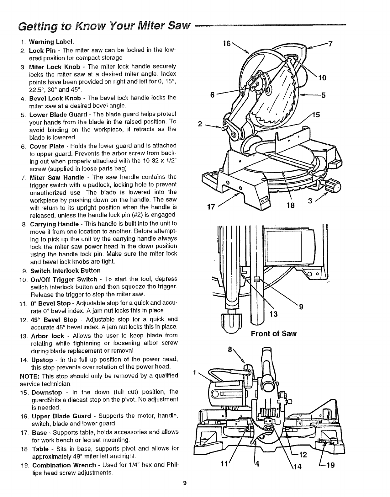
Getting to Know Your Miter Saw
1,, Warning Label,
2. Lock Pin - The miter saw can be locked in the low-
ered position tor compact storage.
3. Miter Lock Knob - The miter lock handle securely
locks the miter saw at a desired miter angle, Index
points have been provided on right and left for 0, 15°,
225 °, 30 ° and 45°,
4 Bevel Lock Knob - The bevel lock handle locks the
miter saw at a desired bevel angle,
5.. Lower Blade Guard - The blade guard helps protect
your hands from the blade in the raised position.,To
avoid binding on the workpiece, it retracts as the
blade is lowered..
6. Cover Plate - Holds the lower guard and is attached
to upper guard.. Prevents the arbor screw from back-
ing out when properly attached with the 10-32 x 1/2"
screw (supplied in loose parts bag)
7., Miter Saw Handle - The saw handle contains the
trigger switch with a padlock, locking hole to prevent
unauthorized use, The blade is lowered into the
workpiece by pushing down on the handle. The saw
will return to its upright position when the handle is
released, unless the handle lock pin (#2) is engaged.
8. Carrying Handle - This handle is built into the unit to
move it from one location to another, Before attempt-
ing to pick up the unit by the carrying handle always
lock the miter saw power head in the down position
using the handle lock pin. Make sure the miter lock
and bevel lock knobs are tight°
9_ Switch Interlock Button,
10.. On/Off Trigger Switch -To start the tool, depress
switch interlock button and then squeeze the trigger.,
Release the trigger to stop the miter saw,,
11. 0°Bevel Stop - Adjustable stop for a quick and accu-
rate 0°bevel index_A jam nut locks this in place
12, 45°Bevel Stop - Adjustable stop for a quick and
accurate 45°bevel index..A jam nut locks this in place.
13, Arbor lock -Allows the user to keep blade from
rotating while tightening or loosening arbor screw
during blade replacement or removal,
14., Upstop - tn the full up position of the power head,
this stop prevents over rotation of the power head..
NOTE: This stop should only be removed by a qualified
service technician
15. Downstop - In the down (full cut) position, the
guardShits a diecast stop on the pivot., No adjustment
is needed.
16. Upper Blade Guard - Supports the motor, handle,
switch, blade and lower guard.
17.. Base -Supports table, holds accessories and allows
for work bench or leg set mounting,
18. Table - Sits in base, supports pivot and allows for
approximately 49 ° miter left and right,
19.. Combination Wrench -Used for 1/4" hex and Phil-
lips head screw adjustments,
6
18 3
11
f_
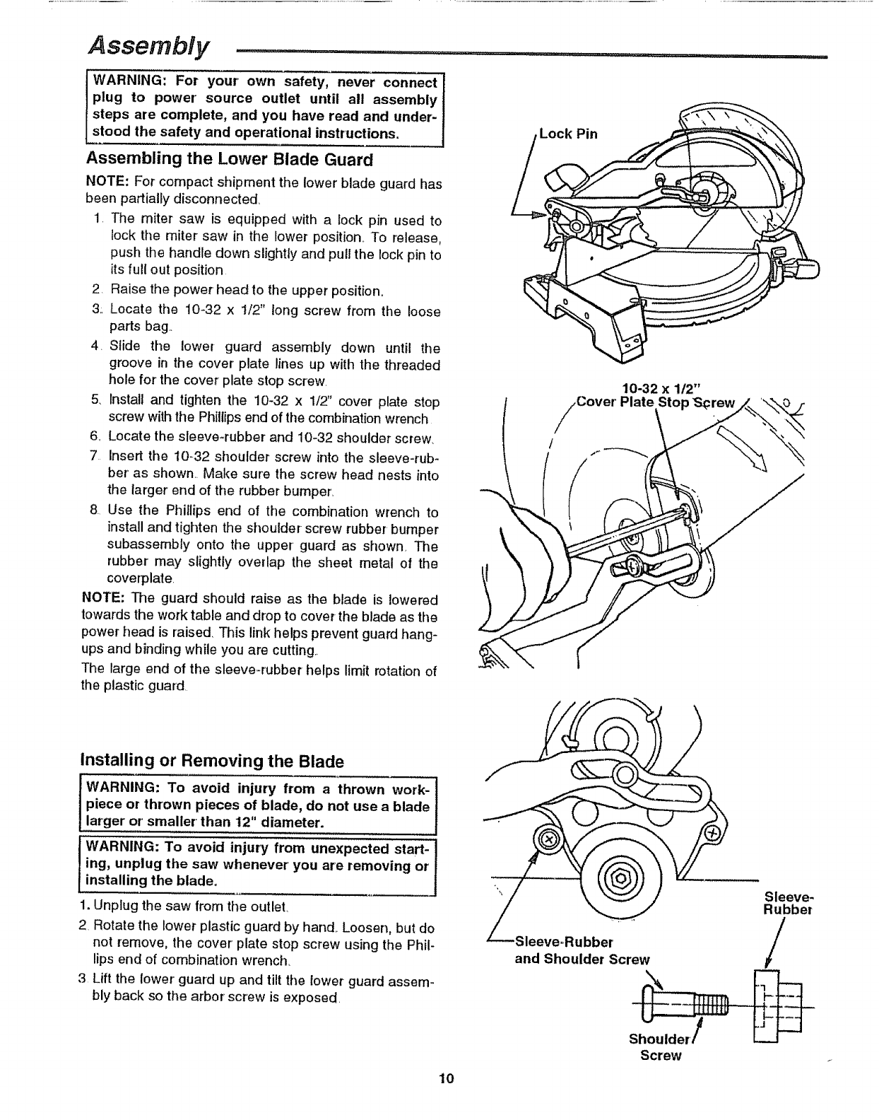
Assembly
WARNING: For your own safety, never connect
plug to power' source outlet until all assembly
steps are complete, and you have read and under'-
stood the safety and operational instructions,
Assembling the Lower Blade Guard
NOTE: For compact shipment the lower blade guard has
been partially disconnected.
1. The miter saw is equipped with a lock pin used to
lock the miter saw in the lower position.. To release,
push the handle down slightly and pull the lock pin to
its full out position
2. Raise the power head to the upper position.
3.+Locate the 10-32 x 1/2" tong screw from the loose
parts bag.+
4+ Slide the lower guard assembly down until the
groove in the cover' plate lines up with the threaded
hole for the cover plate stop screw.
5. Install and tighten the 10-32 x 1/2" cover plate stop
screw withthe Phillips end of the combination wrench
6+ Locate the sleeve+rubber and 10-32 shoulder screw..
7 Insert the 10-32 shoulder screw into the sleeve-rub-
ber' as shown.. Make sure the screw head nests into
the larger end of the rubber bumper.
8. Use the Phillips end of the combination wrench to
install and tighten the shoulder +screw rubber bumper
subassembly onto the upper' guard as shown The
rubber may slightly overlap the sheet metal of the
coverplate
NOTE: Tlle guard should raise as the blade is lowered
towards the work table and drop to cover the blade as the
power head is raised This link helps prevent guard hang-
ups and binding while you are cutting..
The large end of the sleeve+rubber helps limit rotation of
the plastic guard
.Lock Pin
10-32 x 1/2"
Cover' Plate Stop S_rew
/(
Installing or Removing the Blade
WARNING: To avoid injury from a thrown work-
piece or thrown pieces of blade, do not use ablade
larger or' smaller than t2" diameter.
WARNING: To avoid injury from unexpected start-
ing, unplug the saw whenever' you are removing or
installing the blade,
1. Unplug the saw from the outlet.
2 Rotate the lower plastic guard by hand.. Loosen, but do
not remove, the cover' plate stop screw using the Phil-
lips end of combination wrench_
3 Lift the lower guard up and tilt the lower guard assem-
bly back so the arbor screw is exposed.
10
and Shoulder Screw
Sleeve-
Rubber
/
Screw
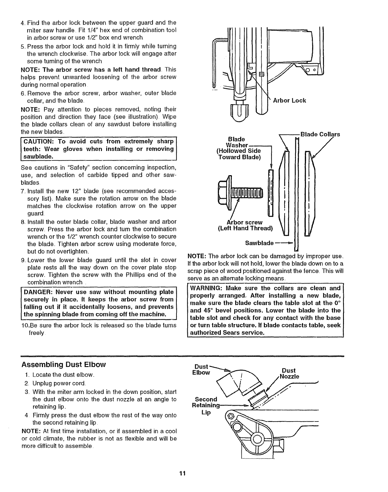
4. Find the arbor lock between the upper guard and the
miter saw handle Fit 1/4" hex end of combination tool
in arbor screw or use 1/2" box end wrench
5.,Press the arbor lock and hold it in lirmfy while turning
the wrench clockwise.. The arbor lock will engage after
some turning of the wrench
NOTE: The arbor screw has a left hand thread, This
helps prevent unwanted loosening of the arbor screw
during normal operation
6. Remove the arbor screw, arbor washer, outer blade
collar, and the blade.
NOTE: Pay attention to pieces removed, noting their
position and direction they face (see illustration) Wipe
the blade collars clean of any sawdust before installing
the new blades.
teeth: Wear gloves when installing or removing
sawblade.
See cautions in "Safety" section concerning inspection,
use, and selection of carbide tipped and other saw-
blades
7. Install the new 12" blade (see recommended acces-
sory list)_ Make sure the rotation arrow on the blade
matches the clockwise rotation arrow on the upper
guard.
8_ Install the outer blade collar, blade washer and arbor
screw Press the arbor lock and tum the combination
wrench or the 1/2" wrench counter clockwise to secure
the blade.. Tighten arbor screw using moderate force,
but do not overtighten.
9. Lower the lower blade guard until the slot in cover
plate rests all the way down on the cover plate stop
screw° Tighten the screw with the Phillips end of the
combination wrench.
DANGER: Never use saw without mounting plate
securely in place, tt keeps the arbor screw from
falling out if it accidentally loosens, and prevents
the spinning blade from coming off the machine.
10.Be sure the arbor lock is released so the blade turns
freely
1
i
I
Arbor Lock
Blade
Washer----.--_
(Hollowed Side I
Toward Blade) 1
screw
(Left Hand Thread)
Sawblade -----_
Collars
NOTE: The arbor lock can be damaged by improper use,
If the arbor lock wilt not hold, lower the blade down on to a
scrap piece of wood positioned against the fence. This will
serve as an attemate locking means.
WARNING: Make sure the collars are clean and
properly arranged. After installing a new blade,
make sure the blade clears the table slot at the 0°
and 45 °bevel positions. Lower the blade into the
table slot and check for any contact with the base
or turn table structure. If blade contacts table, seek
authorized Sears service.
Assembling Dust Elbow
1. Locate the dust elbow..
2. Unplug power cord.
3. With the miter arm locked in the down position, start
the dust elbow onto the dust nozzle at an angle to
retaining lip..
4 Firmly press the dust elbow the rest ol the way onto
the second retaining lip.
NOTE: At first time installation, or if assembled in a cool
or cold climate, the rubber is not as flexible and will be
more difficult to assemble.
Lip
..J
11
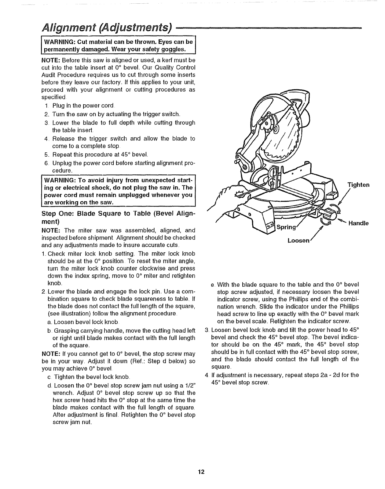
Ah'gnment (Adjustments) ...............................................................
co° e,. owo e,co,, oI
permanently damaged. Wear' your safety goggles,
NOTE: Before this saw is aligned or used, a kerr must be
cut into the table insert at 0°bevel. Our Quality Control
Audit Procedure requires us to cut through some inserts
before they leave our factory.. If this applies to your unit,
proceed with your alignment or cutting procedures as
specified
1 Plug in the powercord
2_ Turn the saw on by actuating the trigger switch..
3 Lower the blade to full depth while cutting through
the table insert.
4, Release the trigger switch and allow the blade to
come to a complete stop
5,_Repeat this procedure at 45 ° bevel°
6 Unplug the power cord before starting alignment pro-
cedure.
WARNING: To avoid injury from unexpected start-
ing or electrical shock, do not plug the saw in. The
power' cord must remain unplugged whenever you
are working on the saw.
Tighten
Step One" Blade Square to Table (Bevel Align-
ment)
NOTE: The miter saw was assembled, aligned, and
inspected before shipment Alignment should be checked
and any adjustments made to insure accurate cuts,
1..Check miter lock knob setting. The miter lock knob
should be at the 0° position To reset the miter angle,
turn the miter lock knob counter' clockwise and press
down the index spring, move to 0° miter and retighten
knob,,
2. Lower the blade and engage the lock pin,. Use a corn-
bination square to check blade squareness to table, If
the blade does not contact the full length of the square,
(see illustration) follow the alignment procedure.
a, Loosen bevel lock knob
b, Grasping carrying handle, move the cutting head left
or right until blade makes contact with the full length
of the square..
NOTE: If you cannot get to 0° bevel, the stop screw may
be in your way. Adjust it down (ReL: Step d below) so
you may achieve 0 ° bevel.
c Tighten the bevel lock knob.
d Loosen the 0° bevel stop screw jam nut using a 1/2"
wrench.. Adjust 0° bevel stop screw up so that the
hex screw head hits the 0° stop at the same time the
blade makes contact with the full length of square.
After adjustment is final. Retighten the 0° bevel stop
screw jam nuL
Spri_osen /
e With the blade square to the table and the 0° bevel
stop screw adjusted, if necessary loosen the bevel
indicator screw, using the Phillips end of the combi-
nation wrench. Slide the indicator under the Phillips
head screw to line up exactly with the 0° bevel mark
on the bevel scale. Retighten the indicator screw.,
3. Loosen bevel lock knob and tilt the power head to 45 °
bevel and check the 45° bevel stop_ The bevel indica-
tor should be on the 45°mark, the 45° bevel stop
should be in full contact with the 45 ° bevel stop screw,
and the blade should contact the full length of the
square.
4 if adjustment is necessary, repeat steps 2a - 2d for the
45° bevel stop screw.
12
Step Two: Blade Square to Fence (Miter Align-
ment)
WARNING: To avoid injury from unexpected start-
ing or electrical shock, do not plug the saw in. The
power cord must remain unplugged whenever you
are working on the saw.
1..To check blade squareness to fence, lock power head
guard in lower position with the lock pin.. Use a combi-
nation square. Place the square against the fence and
next to the blade as illustrated Locate the square
properly so it does not contact the set in the teeth of
sawblade, giving an inaccurate reading The sawblade
should contact the full length of the square.
2. If blade contacts full length of square, no alignment is
necessary, skip a-f below. If blade is not square to the
fence, follow the alignment procedure
a. Loosen miter lock handle a half turn The power
head should still be secured with blade in lowered
position by the lock pin.
NOTE: You must take the saw off its stand, bench or
plywood base if readjustment is necessary
CAUTION; To keep from losing control of the unit,
steady the base with one hand while loosening the
two bolts with the other hand.
b With the unit securely resting on a large stable sur-
face, tilt the unit by lifting up on one side or the other of
the base. Loosen the two miter arm bolts on the
underside of the table with the 1/4" hex end of the
combination wrench (supplied)_
c Return the saw to its normal resting position. Make
sure the miter lock handle is loose but do not release
the index spring
d..Use the miter saw handle to turn the table and pow-
erhead so that the blade contacts the full length of
the square. Turn the miter lock handle clockwise to
lock saw square to fence
e. Tilt saw as in Step b and tighten bolts..
f.. Recheck blade squareness to fence and readjust if
necessary
Adjust Miter Scale Indicator
1..Through the hole in the front of the table insert, loosen
the Phillips screw that holds the indicator in place.
2 Reposition the indicator to align it with 0°mark, and
retighten screw
Step Three; Pivot Adjustment
NOTE: This adjustment was made at the factory and nor-
mally does not require readjustment.
Arm Pivot Movement
1 Verify that cutting head rises, without help, to full "up"
position and guard rests on upstop screwed onto pivot..
2 Make sure the see through lower guard is rotated
closed and is resting against, or very close to, the rub-
ber stops.. If not, see "Lubrication" section
Bevel Scale Indicator
Miter Arm Bolts
Upstop
13
Alignment (Adjustments) (continued) ...... .............. ,,,,
Bevel Pivot Movement/Adjustment
1 Check that miter saw bevels easily by loosening the
bevel lock handle and tilting the power head to the left.
NOTE: At least one thread of the pivot bolt should stick
out past the hex lock nut,.
2 If movement is tight or there is looseness in the pivot,
do the following adjustment procedure:
a. Loosen the bevel lock handle..
b Turn the hex lock nut with a 3/4" socket and socket
wrench..
c. Recheck bevel movement of the miter saw. Readjust
if necessary
Mounting The Miter Saw ...................
WARNING: To avoid injury from unexpected saw
movement:
a. Before moving the saw, lock the miter and bevel
knobs and lock the power head in the lower
position, Unplug electric cord,
b. To avoid back injury, hold the tool close to your
body when lifting. Bend your knees so you can
lift with your legs, not your back° Lift by using
the hand-hold areas at each side of tile bottom
of the base or by the carrying handle=
c. Never carry the miter saw by the power cord or
the trigger grip of the plastic handle. Carrying
the tool by the power cord could cause damage
to the insulation or the wire connections result-
ing in electric shock or fire.
d. Place the saw so other people cannot stand
behind it. Thrown debris could injure people in
its path,
eoPlace the saw on a firm, level surface where
there is plenty of room for handling and prop-
erty supporting the workpiece.
f. Support the saw so the table is level and the
saw does not rock.
g. Bolt or clamp the saw to its support.
Place the saw in the desired location either on a work
bench or the recommended leg set. The base of the saw
has ten holes to mount the miter saw labeled A thru K
Four smaller holes for' "drywall" screws are labeled B, E,
G and K Six holes for 5/16" bolts are labeled A, C, D, F,
H and J (see illustration). If the saw is to be used in one
location, permanently fasten it to the work bench or leg
set.
NOTE: When mounted on a large flat surface, the miter
saw table is 3 1/2" high., A finished 4x4 or a supported
2x4 on edge can be used as work support extension
B_
A
K,
Mounting .Board or Work Surface
c/ 0j
Fo
J, H. G.
14
Portable Applications
To mount the saw to a 3/4" piece of
plywood, use, 4 of the 6, 5/16 bolt
holes o_rrthe 4 drywall screw holes,
The mounting board can then be
clamped down to prevent it from tip-
ping. Plywood mount also helps pro-
tect saw from damage during the
rough handling associated with por-
table miter saw usage.
Work Bench Applications
Mount as specified in portable appli-
cations Check for workpiece clear-
ances to left and right of saw,,
Leg Set Applications
To mount saw to below mentioned
leg set, use holes marked A, F, H
and J,. Attach with hardware shown,
through legset holes indicated by "o"
(below),,
Catalog No. 9_22246 Leg Set
Legset Mounting Holes for
Model 113.235140 Miter Saw
Recommended mounting hardware (not included)
Qty
5/16-i 8x2" hex head bolts (front) ...................................................2
5/16-18x2 1/2" hex head bolts (rear) .........................................2
5/16 Iockwashers ..............................................................................4
5/'16 hex nuts .............................................................................................4
[
L®o oo
o
o
o
o
15
Safety instructions for Basic Saw Operations ................
Before Each Use
inspect your saw.
Disconnect The Miter Saw. To avoid injury from acci-
dental starting, unplug the saw, before changing the
setup, changing the blade or adjusting anything_
Compare the direction of rotation arrow on the guard to
the direction arrow on blade.. The blade teeth should
always point downward at the front of the saw,.
Tighten the arbor screw
Tighten the cover plate stop screw
Check Damaged Parts. Check for:
oAlignment of moving parts,
=Damaged electric cords,
oBinding of moving parts,
oBroken parts,
oStable mounting
oFunction of arm return spring and lower guard: Push
the arm all the way down, then let it rise up until it
stops by itself. Check the lower guard to see if it closed
fully. If it did not, follow the instructions in the Trouble
Shooting section
o Other conditions that may affect the way the miter saw
works
Keep Guards In Place, in working order, and in proper
adjustment
If any part of this miter saw if missing, bent, or broken in
any way, or any electrical parts don't work, turn the saw
off and unplug it Replace damaged, missing, or failed
parts before using the saw again._
Maintain Tools With Care.. Keep the miter saw clean for
best and safest performance_ Follow instructions for lubri-
cating.. DON'T put lubricants on the blade while it's spin-
ning.
Remove Adjusting Keys And Wrenches from tool
before turning it on
To Avoid anjury From Jams, Slips Or Thrown Pieces
oUse Only Recommended Accessories_ (See "Acces-
sory" section within_) Consult this Owner's manual for
recommended accessories Follow the instructions
that come with the accessories.. The use of improper
accessories may cause risk of injury to persons
oChoose the right 12-inch diameter blade for the mate-
rial and the type of cutting you plan to do_
oMake sure the blade is sharp, undamaged and prop-
erly aligned. With the saw unplugged, push the power-
head all the way down. Hand spin the blade and check
for clearance. Tilt the power-head to 45 degree bevel
and repeat the check. If the blade hits anything, make
the adjustments shown in the Maintaining Maximum
Cutting Capacity section
oMake sure the blade and arbor collars are clean.
• Make sure the collars' recessed sides ar_ facing the
blade
=Using 1/4" hex end of combination wrench (supplied)
or 1/2-inch box end wrench, make sure the arbor
screw is firmly hand tightened.
o Make sure all clamps and locks are tight and there is
no excessive play in any parts..
°Keep work area clean, Cluttered areas and benches
invite accidents.. Floor must not be slippery_
To avoid burns or other fire damage, never' use the miter
saw near flammable liquids, vapors or gases.
Plan Ahead To Protect Your Eyes, Hands, Face, Ears
Know your miter' saw, Read and understand the
owner's manual and labels affixed to the tool.. Learn its
application and limitations as well as the specific poten-
tial hazards peculiar to this too!,.
To avoid injury from accidental contact with moving parts,
don't do layout, assembly, or setup work on the miter' saw
while any parts are moving.
Avoid Accidental Starting. Make sure switch is "OFF"
before plugging miter saw into a power outlet..
Plan your work.
Use The Right Tool, Don't force tool or attachment to do
a job it was not designed to do. Use adifferent tool for'
any workpiece that can't be held in a solidly braced, fixed
position
CAUTION: This machine is not designed for' cutting
ferrous metals (steel, iron and iron based metals).
Use this miter saw to cut only wood, wood like
products or soft metals like aluminum. Other mate-
rial may shatter, bind on the blade, or create other'
dangers.
ICAUTION: When cutting any metals, sparks or hot
fragments could cause a fire. To avoid this, discon-
nect any dust collecting bag or' hose from the miter
saw, and remove all traces of wood dust from
inside dust traps in the miter saw.
16
Dress For Safety
WEAR YOUR
Any power miter saw can throw foreign objects into the
eyes° This can result in permanent eye damage_ Wear
safety goggles (not glasses) that comply with ANSI Z87_1
(shown on package). Everyday eyeglasses have only
impact resistant lenses.. They are not safely glasses
Safety goggles are available at Sears retail stores.
Glasses or goggles not in compliance with ANSI Z87_1
could seriously hurt you when they break..
o Do not wear loose clothing, gloves, neckties or jewelry
(rings, wrist watches) They can get caught and draw
you into moving parts,
• Wear nonslip footwear.
° Tie back long hair,
° Roll long sleeves above the elbow.
oNoise levels vary widely. To avoid possible hearing
damage, wear ear plugs or muffs when using miter
saw for hours at a time.
• For dusty operations, wear a dust mask along with
safety goggles..
Inspect Your Workpiece for any workpieces large enough to tip when not held
° Make sure there are no nails or foreign objects in the
part of the workpiece to be cut.
Plan your work to avoid thrown pieces caused when
the workpiece binds on the blade and is torn from
your hands.
Plan the way you will hold the workpiece from start to finish..
Avoid awkward operations and hand positions where a
sudden slip could cause fingers or hand to move into the
blade.
Don't Overreach. Keep good footing and balance.
Keep your face and body to one side of sawblade, out of
line with a possible throwback_
Cut only one workpiece at a time.
Never cut Freehand:
o Brace your workpiece solidly against the fence and
table top so it will not rock or twist during the cut.,
o Make sure there's no debris between the workpiece
and its supports..
• Make sure no gaps between the workpiece, fence and
table wiltlet the workpiece shift after it is cut in two..
° Keep the cut off piece free to move sideways after it's
cut off° Otherwise, it could get wedged against the
blade and could be thrown violently.
oClear everything except the workpiece and related
support devises off the table before turning the miter
saw ono
•Secure Work. Use clamps or a vise to help hold the
work when it's practical.
Use extra caution with large, very small or awkward
workpieces:
• Use extra supports (tables, saw horses, blocks, etco)
down to the table top.
oNever use another person as a substitute for a table
extension, or as additional support for a workpiece that
is longer or wider than the basic miter saw table or to
help feed, support or pull the workpiece..
• Do not use this saw to cut pieces too small to let you
easily hold the work while you keep the thumb side of
your index (pointer) finger against the outside edge of
the fence_
• When cutting irregularly shaped workpieces, plan your
work so it will not slip and pinch the blade and be tom
from your hands,. A piece of molding, for example,
must lie flat or be held by a fixture or jig that will not let
it twist, rock or slip while being cut
•Properly support round material such as dowel rods, or
tubing They have a tendency to roll while being cut,
causing the blade to "bite.," To avoid this, always use a
fixture designed to properly hold your workpiece_.
WARNING: If planning to cut aluminum or other
non-ferrous metals: Under adverse conditions, the
blade can grab and throw the workpiece suddenly
and unexpectedly. To avoid injury, follow all appli-
cable safety instructions, as you normally would,
and:
oUse only sawblades specifically recommended
for non-ferrous metal cutting.
•Do not cut metal workpieces that must be hand
held. Use auxiliary clamps or other equipment as
needed.
oCut non-ferrous metals only if you are experi-
enced or under the supervision of an experienced
person.
Whenever Saw Is Running
WARNING: Don't allow familiarity (gained from fre-
quent use of your miter saw) cause a careless mis-
take. A careless fraction of a second is enough to
cause a severe injury.
Before starting your cut, watch the miter saw while it
runs. tf it makes an unfamiliar noise or vibrates a lot, stop
immediately.. Turn the saw off. Unplug the saw_ Do not
restart until finding and correcting the problem
Keep Children Away Keep all visitors a safe distance
from the miter saw Make sure bystanders are clear of
the miter saw and workpiece
Never confine the piece being cut off. Never hold it,
clamp it, touch it, or use length stops against it while the
blade is spinning.. It must be free to move sideways on its
own° If confined, it could get wedged against the blade
and thrown violently
17
Safety instructions for Basic Saw Operations (continued)
Let the blade reach full speed before cutting. This will
help avoid athrown workpiece,
Don't Force Tool, It will do the job better and safer at its
designed rate Feed the saw into the workpiece only fast
enough to let the blade cut without bogging down or' bind-
ing,,
Before freeing jammed material:
• Turn miter saw "OFF" by releasing trigger switch.
°Wait for all moving parts to stop
• Unplug the miter saw
After finishing a cut:
°Keep holding the power head down_
. Release the switch, and wait for alt moving parts to
stop before moving your hands or raising power head_
o If blade doesn't stop within 6 seconds, unplug the saw
and follow the instructions in the Trouble Shooting sec-
tion for fixing the blade brake before using the saw again
Before Leaving The Saw:
Never' Leave Tool Running Unattended.Turn power
off. Wait for all moving parts to stop,
Make workshop child-proof. Install a padlock through
the hole provided in the trigger' to prevent unauthorized,
usages.Lock the shop Disconnect master switches_ Store
tool away from children and others not qualified to use
the tool.
Basic Saw Operations
WARNING: For your convenient use, your saw has
ablade brake. The brake is not a safety device.
Never rely on it to replace proper' use of the guard
on your saw. If the blade does not stop within 6
seconds, unplug the saw and follow the instruc-
tions in the Trouble Shooting section for fixing the
brake before using saw again.
Body and Hand Position
Proper positioningof your body and hands when operating
tile miter saw wiU make cutting easier and safer Never
place hands near cutting area, Place hand at least 4" from
path of blade Hold workpiece firmly to the fence to prevent
movement toward the blade Keep hands in position until
trigger has been released and the blade has completely
stopped Before making a cut, make a"dry run" with the
power'off so you can see the path of the blade_
lWARNING: Do not try to cut short pieces, you cannot ]
properly support the workpiece _keep your hold /
down hand the required distance from the blade.
\
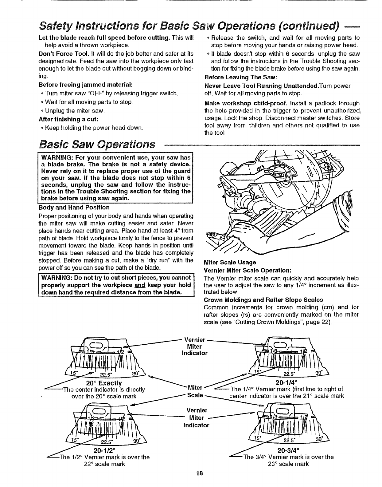
Miter Scale Usage
Vernier Miter' Scale Operation:
The Vernier miter scale can quickly and accurately help
the user to adjust the saw to any 1/4 ° increment as iUus-
trated below
Crown Moldings and Rafter Slope Scales
Common increments for crown molding (cm) and for
rafter slopes (rs) are conveniently marked on the miter
scale (see "Cutting Crown Moldings", page 22),
20 °Exactly
ie center indicator is directly
over the 20 ° scale mark
22.5° 30_
20-112 °
1/2 ° Vernier mark is over the
22°scale mark
Vernier
Miter
Indicator
22.5" 30°.._
20-1/4 °
The t/4 ° Vernier mark (first line to right of
....-----Scale --*-..._.__tor is over the 21° scale mark
Vernier _
E
"Miter --_ '_!_=_
_/ 20-3/4 °
_The 3/4_ Ve_ is over the
23° scale mark
18
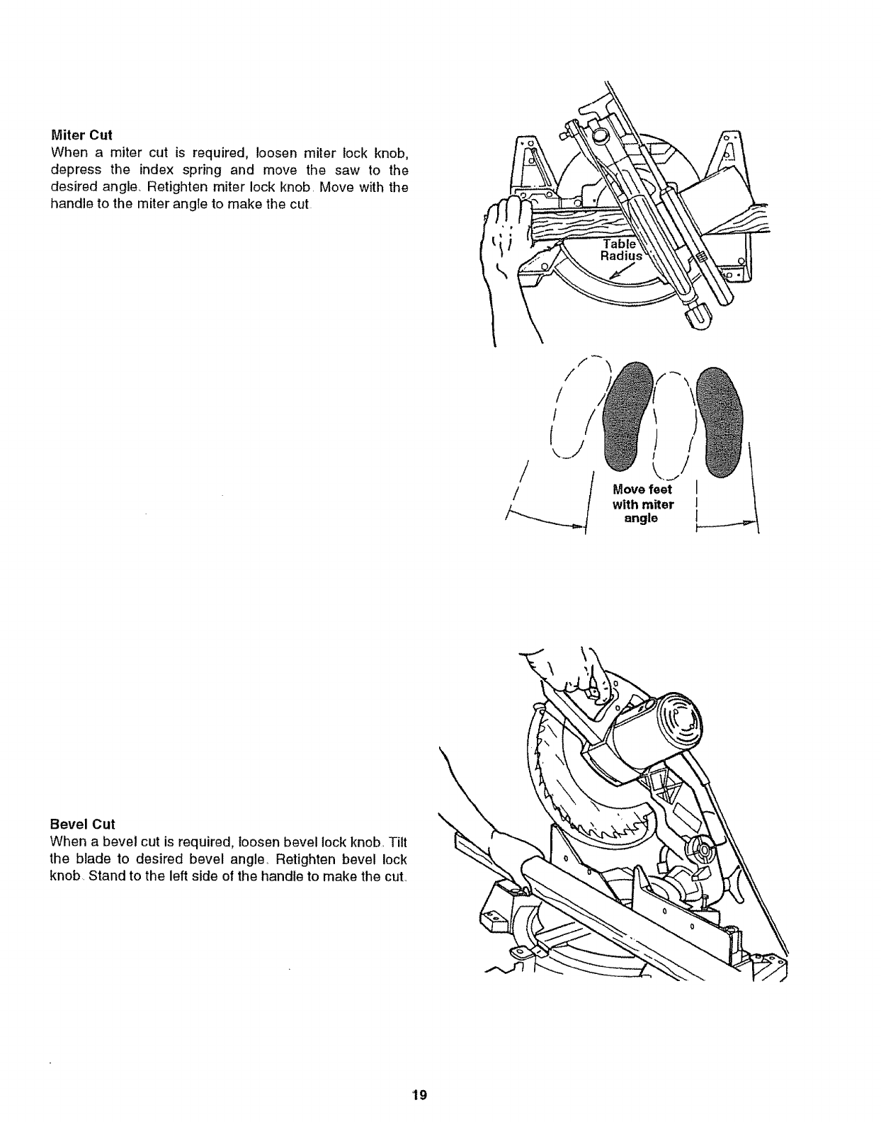
MiterCut
Whena mitercut is required,loosenmiterlockknob,
depressthe indexspringand movethe saw to the
desiredangle,Retightenmiterlockknob,Movewiththe
handletothemiterangletomakethecut
Move feet
with miter
angle
Bevel Cut
When a bevel cut is required, loosen bevel lock knob, Tilt
the blade to desired bevel angle_ Retighten bevel lock
knob, Stand to the left side of the handle to make the cut.,
19
Basic Saw Operations (continued) .........................................,.......................
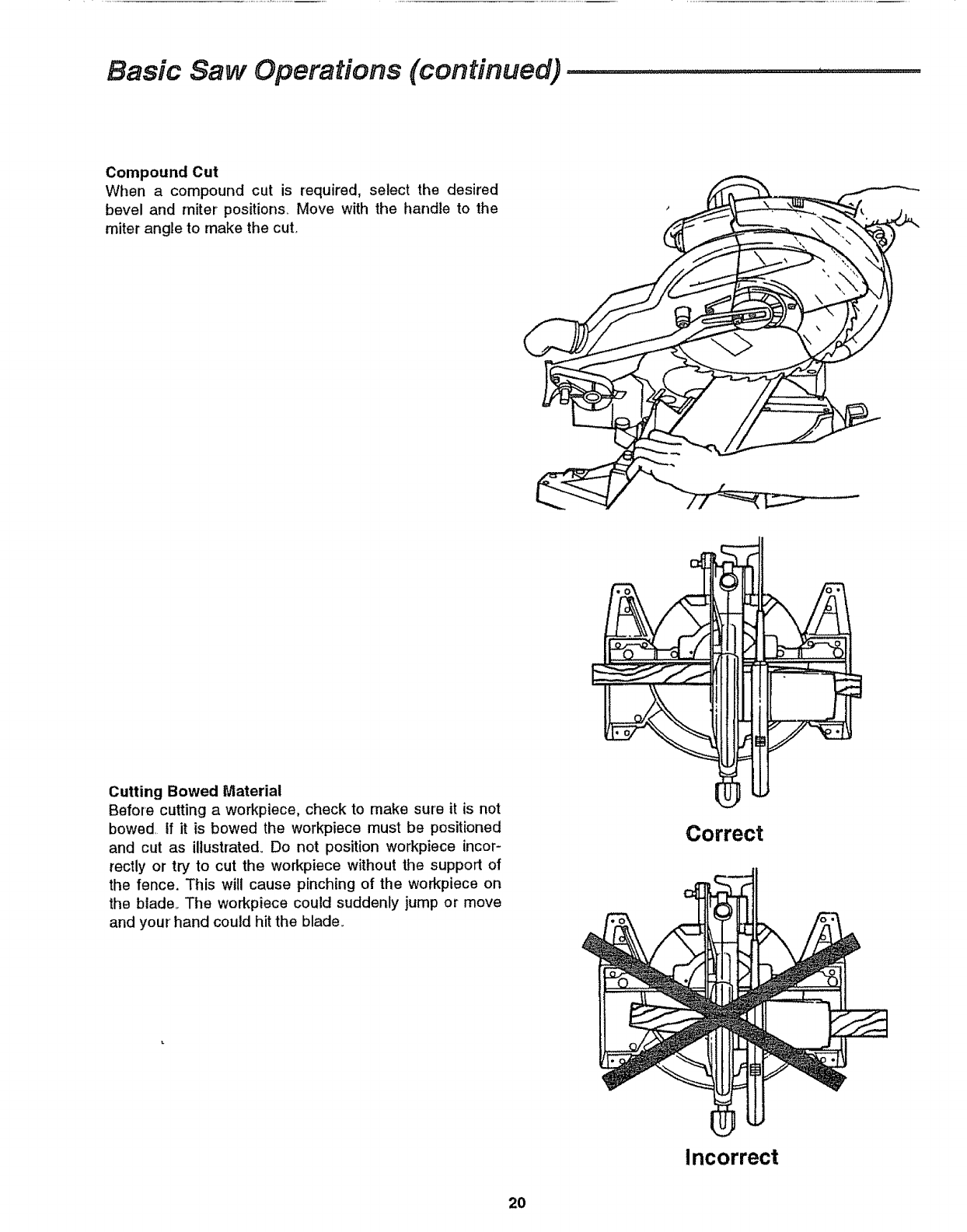
Compound Cut
When a compound cut is required, select the desired
bevel and miter positions.. Move with the handle to the
miter angle to make the cut.
t
Cutting Bowed Material
Before cutting a workpiece, check to make sure it is not
bowed, tf it is bowed the workpiece must be positioned
and cut as illustrated.. Do not position workpiece incor-
rectly or try to cut the workpiece without the support of
the fence. This will cause pinching of the workpiece on
the blade.. The workpiece could suddenly jump or move
and your' hand could hit the blade..
Correct
Incorrect
2O
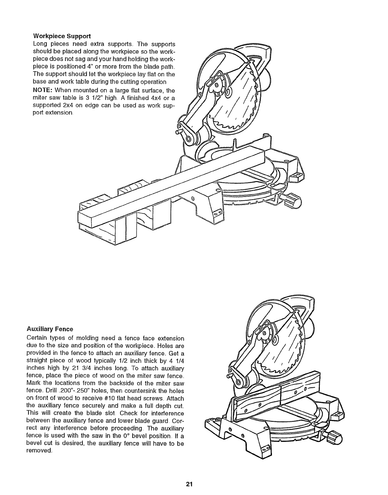
Workpiece Support
Long pieces need extra supports. The supports
should be placed along the workpiece so the work-
piece does not sag and your hand holding the work-
piece is positioned 4" or more from the blade path,
The support should let the workpiece lay flat on the
base and work table during the cutting operation
NOTE: When mounted on a large flat surface, the
miter saw table is 3 1/2" high. A finished 4x4 or a
supported 2x4 on edge can be used as work sup-
port extension.
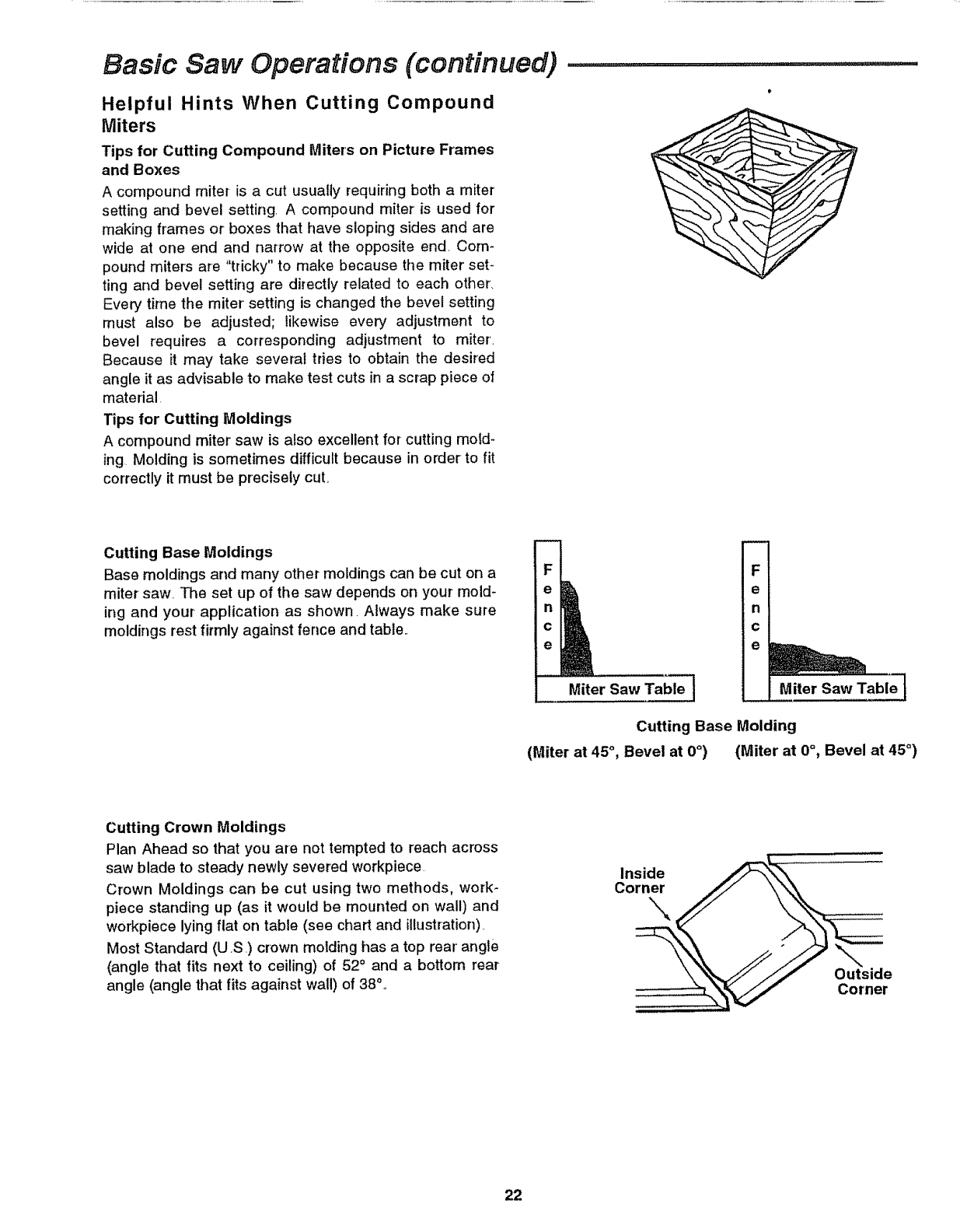
Auxiliary Fence
Certain types of molding need a fence face extension
due to the size and position of the workpiece, Holes are
provided in the fence to attach an auxiliary fence,. Get a
straight piece of wood typically 1/2 inch thick by 4 1/4
inches high by 21 3/4 inches long,, To attach auxiliary
fence, place the piece of wood on the miter saw fencer
Mark the locations from the backside of the miter saw
fence° Drill .200"-250" holes, then countersink the holes
on front of wood to receive #10 flat head screws., Attach
the auxiliary fence securely and make a full depth cut.,
This wilt create the blade slot. Check for interference
between the auxiliary fence and lower blade guard. Cor-
rect any interference before proceeding. The auxiliary
fence is used with the saw in the 0° bevel position If a
bevel cut is desired, the auxiliary fence will have to be
removed,.
21
Basic Saw Operations (continued)
Helpful Hints When Cutting Compound
Miters
Tips for Cutting Compound Miters on Picture Frames
and Boxes
A compound miter-is a cut usually requiring both a miter
setting and bevel setting A compound miter is used for
making frames or boxes that have sloping sides and are
wide at one end and narrow at the opposite end. Com-
pound miter:s are "tricky" to make because the miter set-
ting and bevel setting are directly related to each other,
Every time the miter setting is changed the bevel setting
must also be adjusted; likewise every adjustment to
bevel requires a corresponding adjustment to miter.
Because it may take several tries to obtain the desired
angle it as advisable to make test cuts in a scrap piece of
material.
Tips for Cutting Moldings
A compound miter saw is also excellent for cutting mold-
ing, Molding is sometimes difficult because in order to fit
corTectly it must be precisely cut,
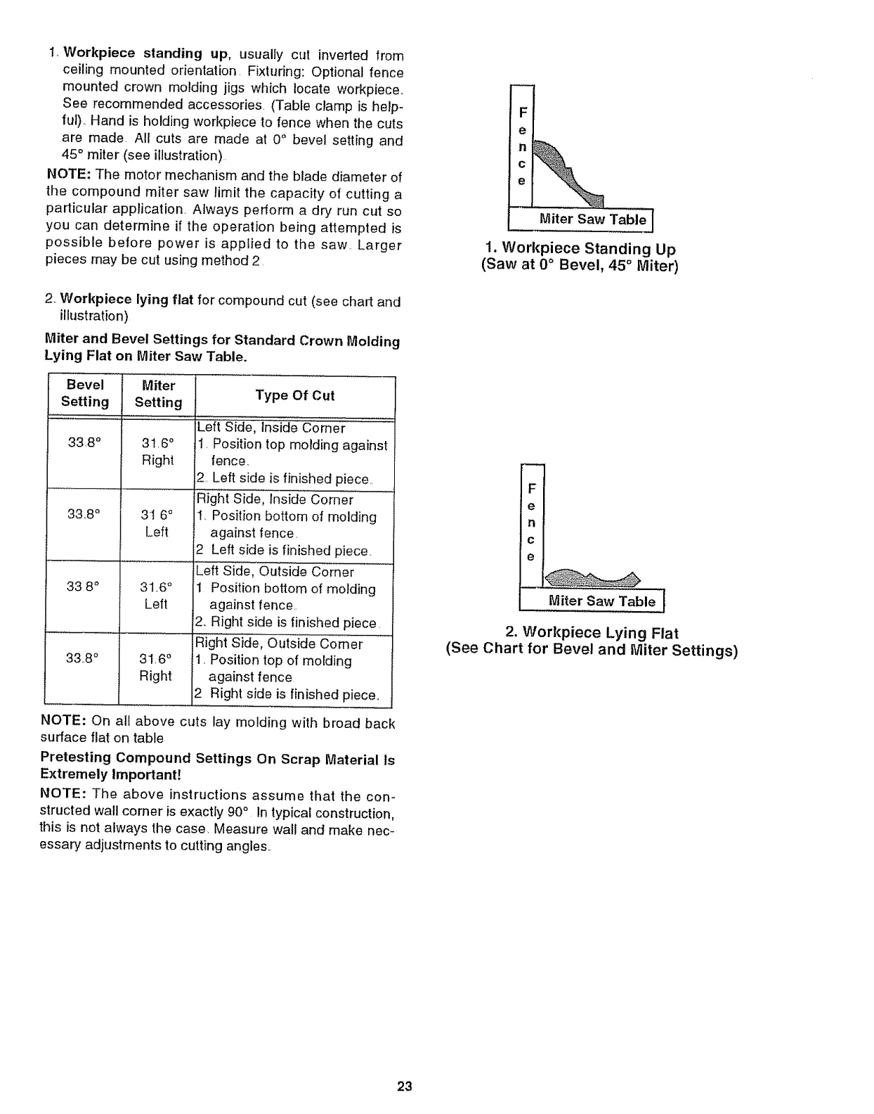
Cutting Base Moldings
Base moldings and many other moldings can be cut on a
miter saw, The set up of the saw depends on your mold-
ing and your application as shown. Always make sure
moldings rest firmly against fence and table,,
m
F
n
c
e
Miter Saw Tabl_
m
F _
e
n
c
e
Miter Saw Table--J
Cutting Base Molding
(Miter at 45°, Bevel at 0°) (Miter at 0°, Bevel at 45°)
Cutting Crown Moldings
Plan Ahead so that you are not tempted to reach across
saw blade to steady newly severed workpiece
Crown Moldings can be cut using two methods, work-
piece standing up (as it would be mounted on wall) and
workpiece lying flat on table (see chart and illustration)
Most Standard (U ,S) crown motding has a top rear angle
(angle that fits next to ceiling) of 52° and abottom rear
angle (angle that fits against wall) of 38%
22
1Workpiece standing up, usually cut inverted from
ceiling mounted orientation Fixturing: Optional fence
mounted crown molding jigs w!_ich locate workplace.
See recommended accessories (Table clamp is help-
ful). Hand is holding workpiece to fence when the cuts
are made All cuts are made at 0° bevel setting and
45 ° miter (see illustration)
NOTE: The motor mechanism and the blade diameter of
the compound miter saw limit the capacity of cutting a
particular application Always perform a dry run cut so
you can determine if the operation being attempted is
possible before power is applied to the saw Larger
pieces may be cut using method 2
_el
Miter Saw Table J
1. Workpiece Standing Up
(Saw at 0°Bevel, 45 ° Miter)
2 Workplace lying flat for compound cut (see chart and
illustration)
Miter and Bevel Settings for Standard Crown Molding
Lying Flat on Miter Saw Table.
Bevel
Setting
33,8 °
33 8 °
33 8 °
33.8 °
lMiterSetting
31,6 °
Right
31 6°
Left
3t 6 °
Left
316 °
Right
Type Of Cut
Lef'{'Side, Ins)ae corner ..........
I. Position top molding against
fence..
2.. Left side is finished piece..
Right Side, Inside Corner
1..Position bottom of molding
against fence.
2 Left side is finished piece.
Left Side, Outside Corner
1 Position bottom of molding
against fence..
i2..Right side is finished piece
Right Side, Outside Comer
1Position top of molding
against fence
2 Right side is finished piece,.
NOTE: On all above cuts lay molding with broad back
surface flat on table
Pretesting Compound Settings On Scrap Material Is
Extremely Important!
NOTE: The above instructions assume that the con-
structed wall comer is exactly 90° In typical construction,
this is not always the case. Measure wall and make nec-
essary adjustments to cutting angles.
FI
eI
nl
cI
e 1
Miter Saw Table I
2. Workpiece Lying Flat
(See Chart for Bevel and Miter Settings)
23
Maintenance and Lubrication
Maintenance
DANGER: Never put lubricants on the blade while it
is spinning.
WARNING: To avoid injury from unexpected start-
ing or electrical shock, unplug the power cord
before working on the saw.
Replacing Carbon Brushes
The carbon brushes furnished will last approximately 50
hours of running time or 10,000 on/off cycles. Replace
both carbon brushes when either has less than 1/4"
length of carbon remaining To inspect or replace
brushes, first unplug the saw Then remove the black
plastic cap on the side of the motor (caution, this cap is
spring loaded by the brush assembly). Then pull out the
brush.. Repeat for the other' side To reassemble reverse
the procedure.. The ears on the metal end of the brush
assembly go in the same hole the carbon part fits into..
Tighten the cap snugly but do not overtighten.,
NOTE: To reinstall the same brushes, first make sure the
brushes go back in the way they came out Otherwise a
break-in period will occur that wil! reduce motor perfor-
mance and increase brush wear.
Lower Blade Guard
Do not use the saw without the lower guard The lower'
blade guard is attached to the saw for your protection
Should the lower' guard become damaged, do not use the
saw until damaged guard has been replaced.. Develop a
regular check to make sure the lower guard is working
property._Clean the lower guard of any dust or build up
with a damp cloth.
ICAUTION: Do not use solvents on the guard. They I
could make the plastic "cloudy" and brittle, I
IWARNING: When cleaning lower guard unplug the i
saw from the outlet to avoid unexpected start-up.
Periodically, sawdust will accumulate under the work
table and base This could cause difficulty in the move-
ment of the work table when setting up a miter cut Fre-
quently blow out or vacuum up the sawdustCheck up
stop, down stop and bevel stops for sawdust accumula-
tion, which can affect capacity or accuracy_
iWARNtNG: If blowing sawdust, wear proper eye i
protection to keep debris from blowing into eyes.
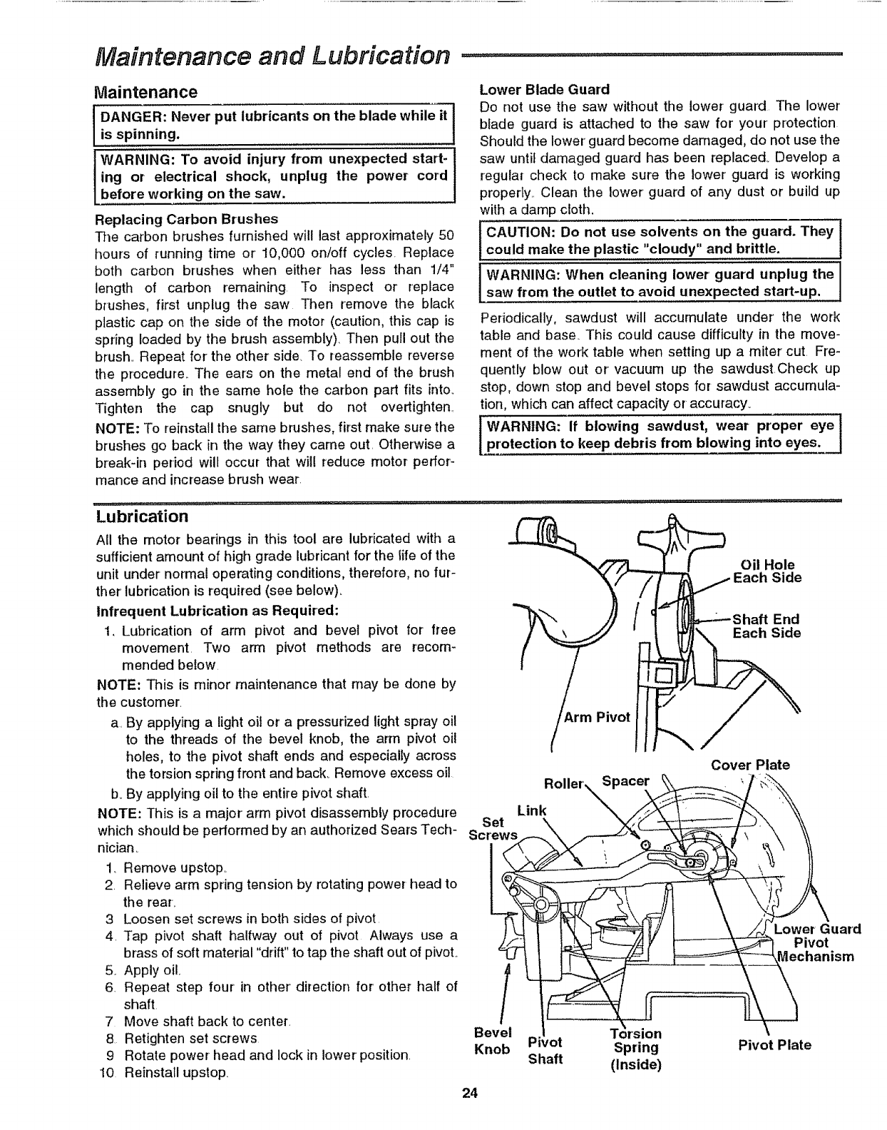
Lubrication
All the motor bearings in this tool are lubricated with a
sufficient amount of high grade lubricant for the tile of the
unit under normal operating conditions, therefore, no fur-
ther lubrication is required (see below).
Infrequent Lubrication as Required:
t. Lubrication of arm pivot and bevel pivot for free
movement. Two arm pivot methods are recom-
mended below,
NOTE: This is minor maintenance that may be done by
the customer.
a. By applying a light oil or a pressurized light spray oil
to the threads of the bevel knob, the arm pivot oil
holes, to the pivot shaft ends and especially across
the torsion spring front and back_ Remove excess oil
boBy applying oil to the entire pivot shaft
NOTE: This is a major arm pivot disassembly procedure
which should be performed by an authorized Sears Tech-
nician..
1.. Remove upstop..
2 Relieve arm spring tension by rotating power head to
the rear..
3 Loosen set screws in both sides of pivot
4. Tap pivot shaft halfway out of pivot Always use a
brass of soft material "drift" to tap the shaft out of pivoL
5. Apply oil..
6. Repeat step four in other' direction for' other half of
shaft.
7 Move shaft back to center.
8 Retighten set screws
9 Rotate power head and lock in lower position.
10 Reinstall upstop
Link
Set
Screws
Pivot
24
Spacer
f rJ
Bevel Torsion
Knob Spring
Shaft (Inside)
Oil Hole
Side
End
Each Side
Cover Plate
Lower Guard
Pivot
lechanism
Pivot Plate
Maintenance and Lubrication
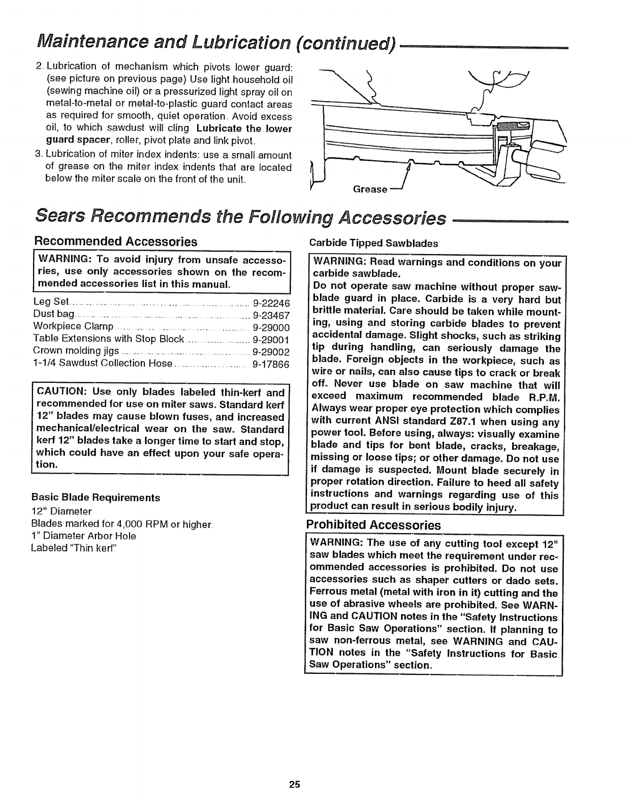
2, Lubrication of mechanism which pivots lower guard:
(see picture on previous page) Use light household oil
(sewing machine oil) or a pressurized light spray oil on
metal-to-metal or metaHo-plastic guard contact areas
as required for smooth, quiet operation. Avoid excess
oil, to which sawdust will cling Lubricate the lower
guard spacer, roller, pivot plate and link pivot..
3. Lubrication of miter index indents: use a small amount
of grease on the miter index indents that are located
below the miter scale on the front of the unit..
(continued) ..........................
Sears Recommends the Following Accessories .........................
Recommended Accessories
WARNING: To avoid injury from unsafe accesso-
ries, use only accessories shown on the recom-
mended accessories list in this manual.
Leg Set ......................................................................................9-22246
Dust bag ...............................................................................9-23467
Workpiece Clamp .......................................................9-29000
Table Extensions with Stop Block ..................................9-29001
Crown molding jigs ............................................................9-29002
1-1/4 Sawdust Collection Hose ...................................9-17866
CAUTION: Use only blades labeled thin-kerr and
recommended for use on miter saws. Standard kerf
12" blades may cause blown fuses, and increased
mechanical/electrical wear on the saw° Standard
kerr 12" blades take a longer time to start and stop,
which could have an effect upon your safe opera-
tion.
Basic Blade Requirements
12" Diameter
Blades marked for 4,000 RPM or higher
1" Diameter Arbor Hole
Labeled "Thin ked"
Carbide Tipped Sawblades
WARNING: Read warnings and conditions on your
carbide sawblade.
Do not operate saw machine without proper saw-
blade guard in place. Carbide is a very hard but
brittle material. Care should be taken while mount-
ing, using and storing carbide blades to prevent
accidental damage. Slight shocks, such as striking
tip during handling, can seriously damage the
blade. Foreign objects in the workpiece, such as
wire or nails, can also cause tips to crack or break
off. Never use blade on saw machine that will
exceed maximum recommended blade R°P.M.
Always wear proper eye protection which complies
with current ANSI standard Z87.1 when using any
power tool. Before using, always: visually examine
blade and tips for bent blade, cracks, breakage,
missing or loose tips; or other damage. Do not use
if damage is suspected. Mount blade securely in
proper rotation direction. Failure to heed all safety
instructions and warnings regarding use of this
product can result in serious bodily injury.
Prohibited Accessories
WARNING: The use of any cutting tool except 12"
saw blades which meet the requirement under rec-
ommended accessories is prohibited. Do not use
accessories such as shaper cutters or dado sets.
Ferrous metal (metal with iron in it) cutting and the
use of abrasive wheels are prohibited. See WARN-
ING and CAUTION notes in the "Safety Instructions
for Basic Saw Operations" section. If planning to
saw non-ferrous metal, see WARNING and CAU-
TION notes in the "Safety Instructions for Basic
Saw Operations" section.
25
Troubleshooting Guide
Motor
Problem Probable Cause
r _'_;,,;;;;;;;,;, "'"'",,', ,,,_;,; ' i............ : ....................
Brake does not stop l_Brushes not seated or
blade within 6 second& lightly sticking
2. Motor brake winding
overheated from use of
prohibited accessory or
rapid on/off cycling,_
3, Arbor screw loose,,
4,_Other
Suggested Corrective Action
-Inspect/cleanheptace brushes_ See "Mainte-
nance" section,,
-Use onfy recommended blades/accessories,
- Let motor' cool down,_
Motor does not start.
Brush sparking
switch released,
when
- Retighten
- Get authorized Sears service. See "Trouble-
shooting of brake" section,.
1. Fuse - 15 amp time delay fuse, or circuit breaker.
2_ Brushes worn. - See "Maintenance" section..
3, Other,. -Get authorized Sears service,,
1. Normal automatic -None
brake working prop-
erly_
General
Blade hits table, 1,,Misalignment -Get authorized Sears Service
Angle of cut not accurate. 1, Misalignment - See "Alignment" section,
Problem Probable Cause Suggested Corrective Action
Can't move miter adjust-
ment
Power head wobble&
Power head won't fully 1 Lubrication needed
rise or blade guard won't 2o Part failure
fully close 3, Pivot spring or guard
1,,Sawdust under table - Vacuum or blow out dust,
Wear Eye Protection,
1_Loose pivot points - See Bevel Pivot Adjustment in "Alignment" sec-
spring not replaces
properly after service
4_Sawdust sticking to
stops
Improper operation
Dull blade
Improper blade
Bent blade - check
across expansion slots
1, Sawblade not round
2. Sawblade damaged
3. Sawblade loose
4, Other
1. Lube needed
tion.
- See "Lubrication" section,
- Get authorized Sears Service..
- Get authorized Sears Service
- inspect/clean stops,,
- See "Basic Saw Operation" section,
- Replace or sharpen blade,,
- Replace with 12" diameter blade designed for the
material being cut,
- Replace blade,.
- Replace blade,
- Replace blade_
- Tighten arbor screw,
- Get authorized Sears Service,,
See -"Lubrication" section
Blade binds, jams, bums t
wood. 2,
Rough cuts 3,
4,
Tool vibrates or shakes
Power head hard to puiV
push down
26
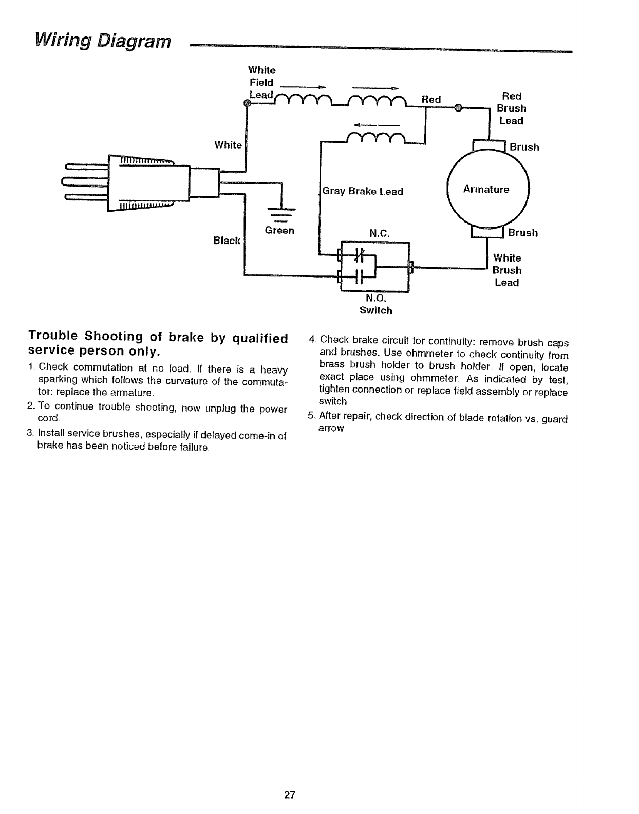
Wiring Diagram . : ....... :........:::._. .......
White
Field __. __, Red
N,O_
Switch
Trouble Shooting of brake by qualified
service person only.
1..Check commutation at no load,, If there is a heavy
sparking which follows the curvature of the commuta-
tor: replace the armature°
2..To continue trouble shooting, now unplug the power
cord.
3.,Install service brushes, especially if delayed come-in of
brake has been noticed before failure°
4. Check brake circuit for continuity: remove brush caps
and brushes.. Use ohmmeter to check continuity from
brass brush holder to brush holder. If open, locate
exact place using ohmmeters, As indicated by test,
tighten connection or replace field assembly or replace
switch
5. After repair, check direction of blade rotation vs., guard
arrow,
27
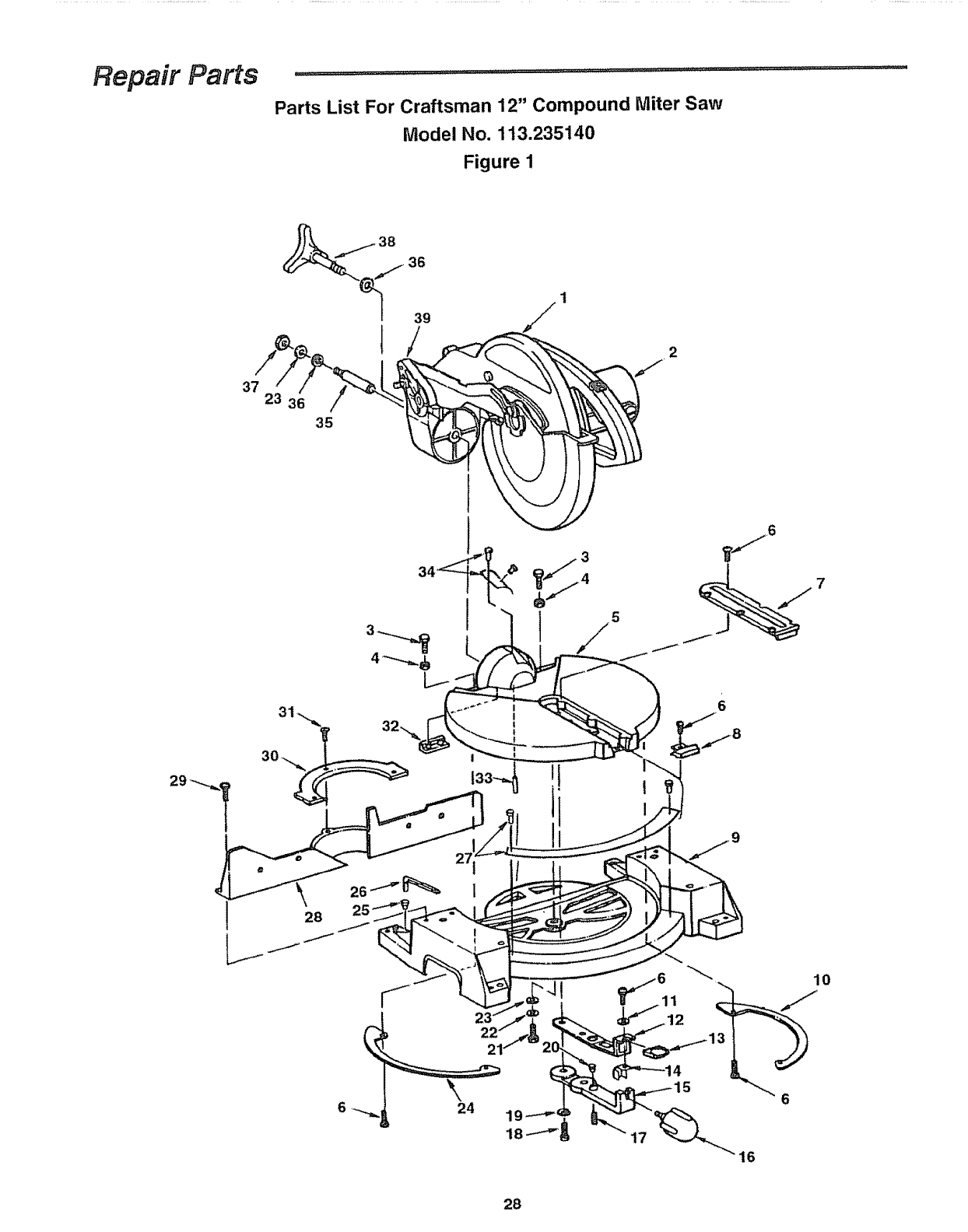
Repair Parts ......................................' .........................................................................................
Parts List For Craftsman 12" Compound Miter Saw
Model No. 113.235140
Figure 1
37 23 3
35
2
610
16
28
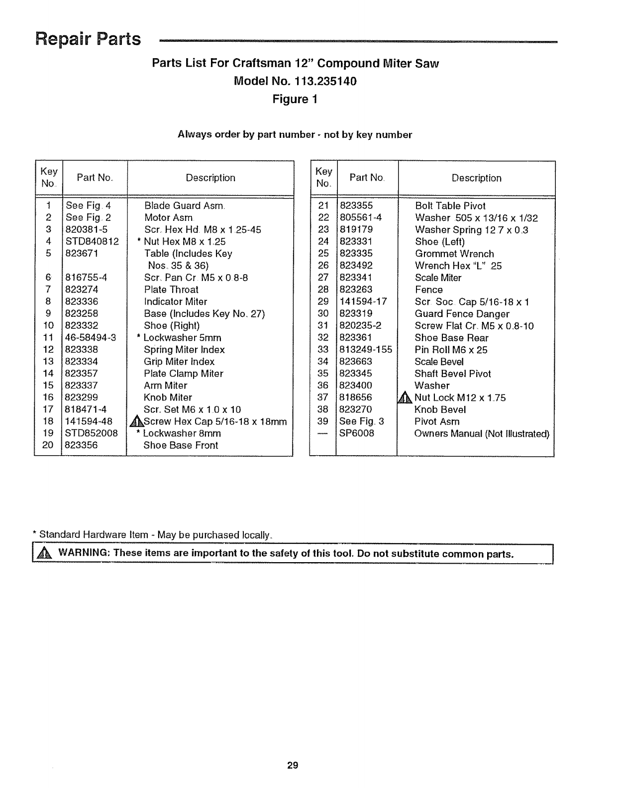
Repair Parts .......................
Parts List For Craftsman 12" Compound Miter Saw
Model No. 113.235140
Figure 1
Always order by part number -not by key number
Key Part No,, Description
No.
1
2
3
4
5
See Fig. 4
See Fig. 2
820381-5
STD840812
823671
6 816755-4
7 823274
8 823336
9 823258
t0 823332
11 46-58494-3
12 823338
13 823334
14 823357
15 823337
t6 823299
17 818471-4
18 t41594-48
19 STD852008
20 823356
Blade" Guard Asm
Motor Asm
Scr,. Hex Hd. M8 x 1.25-45
* Nut Hex M8 x 1.25
Table (includes Key
Nos,, 35 & 36)
Scr, Pan Cr M5 x 0 8-8
Plate Throat
Indicator Miter
Base (Includes Key Nol, 27)
Shoe (Right)
* Lockwasher 5ram
Spring Miter Index
Grip Miter Index
Plate Clamp Miter
Arm Miter
Knob Miter
Scro Set M6 x 1,0 x i0
,_Screw Hex Cap 5/16-18 x 18mm
* Lockwasher 8ram
Shoe Base Front
Key Pa_ No,
Noo
21 823355
22 805561-4
23 819179
24 823331
25 823335
26 823492
27 823341
28 823263
29 I41594-17
30 823319
31 820235-2
32 823361
33 813249-155
34 E823663
35 823345
36 823400
37 i8t8656
38 i823270
39 !See Fig3
SP6008
Description
Bolt Table Pivot
Washer 505 x 13/16 x 1/32
Washer Spring I2 7 x 0,3
Shoe (Left)
Grommet Wrench
Wrench Hex "L" 25
i Scale Miter
Fence
Scr Soc Cap 5/16-18 x 1
Guard Fence Danger
Screw Flat Cr, M5 x 0.,8-10
Shoe Base Rear
Pin Roll M6 x 25
Scale Bevel
Shaft Bevel Pivot
Washer
_Nut Lock M12 x 1_,75
Knob Bevel
Pivot Asm
Owners Manual (Not Illustrated)
* Standard Hardware Item -May be purchased locally.
IA_k WARNING: These items are important to the safety of this tool. Do not substitute common parts. 1
29
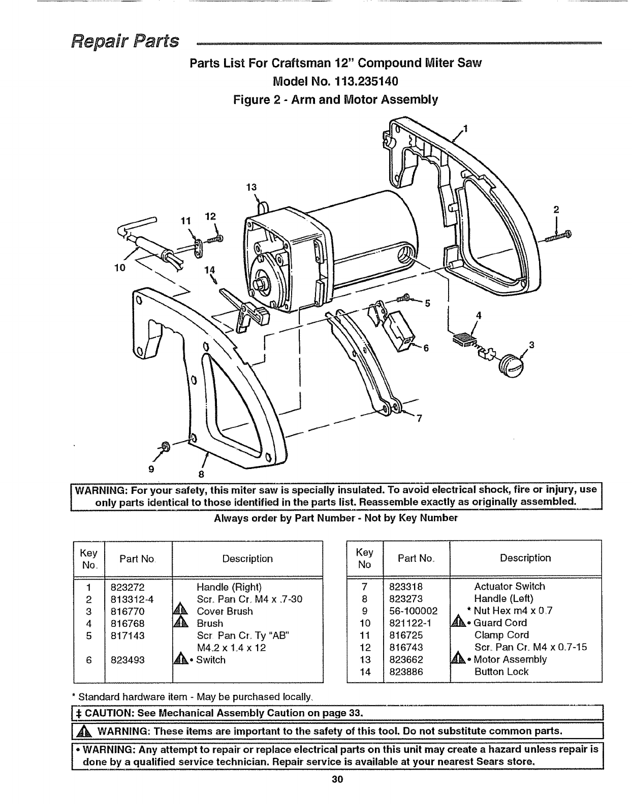
Repair Parts
Parts List For Craftsman 12" Compound Miter Saw
Model No. 113.235140
Figure 2 - Arm and Motor Assembly
13
2
98
!WARNING: For your' safety, this miter saw is specially insulated. To avoid electrical shock, fire or injury, use /
ionly parts identical to those identified in the parts list, Reassemble exactly as originally assembled. J
Always order by Part Number- Not by Key Number
b
Key
No,
1
2
3
4
5
Part No, Description
823272
813312-4
816770
816768
817143
823493
Handle (Right)
Scr,. Pan Cr_ M4 x _7-30
_ over Brush
Brush
Scr Pan Cr. Ty "AB"
M4.,2 x t .,4x 12
,_- Switch
Key Part No_
No
7 823318
8 823273
9 56-100002
10 821122-1
11 816725
12 816743
!3 823662
14 823886
Description
Actuator Switch
Handle (Left)
* Nut Hex m4 x 0,7
_1_° Guard Cord
Clamp Cord
Scr,, Pan Cr. M4 x 0_7-15
,d_o Motor Assembly
Button Lock
* Standard hardware item - May be purchased locally,
[_: CAUTION: See Mechanical Assembly Caution on page 33. t
{_ WARNING: These items are important to the safety of this tool, Do not substitute common parts. {
°WARNING: Any attempt to repair or replace electrical parts on this unit may create a hazard unless repair is {
done by a qualified service technician. Repair service is available at your nearest Sears store, I
3O
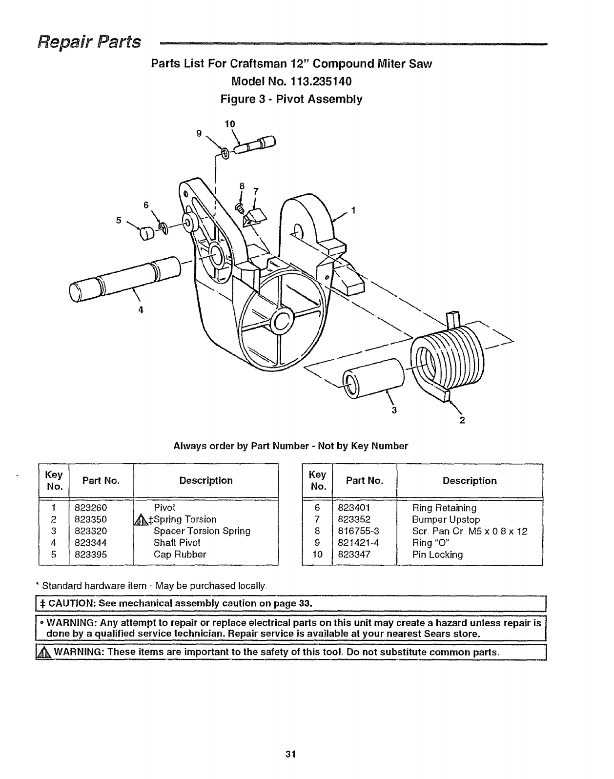
Repair Parts ..........
6
4
Parts List For Craftsman 12" Compound Miter Saw
Model No. 113.235140
Figure 3 -Pivot Assembly
10
87
1
2
Always order by Part Number -Not by Key Number
Part No, Description
Key
No.
...............
2
3
4
5
823260
823350
823320
823344
823395
Pivot
_k:I:Spring Torsion
Spacer Torsion Spring
Shaft Pivot
Cap Rubber
Key
No. Part No. Description
6 823401 Ring Retaining
7 823352 Bumper Upstop
8 816755-3 Scr Pan Cr M5 x 08 x 12
9 821421-4 Ring "O"
10 823347 Pin Locking
* Standard hardware item - May be purchased locally
i_ CAUTION: See mechanical caution 33, l
assembly on page
i oWARNING: Any attempt to repair or replace electrical parts on this unit may create a hazard unless repair is J
done by a qualified service technician. Repair service is available at your nearest Sears store, I
_ _IA_kWARNING: These items are important to the safety of this tool. Do not substitute common parts° t
J
31
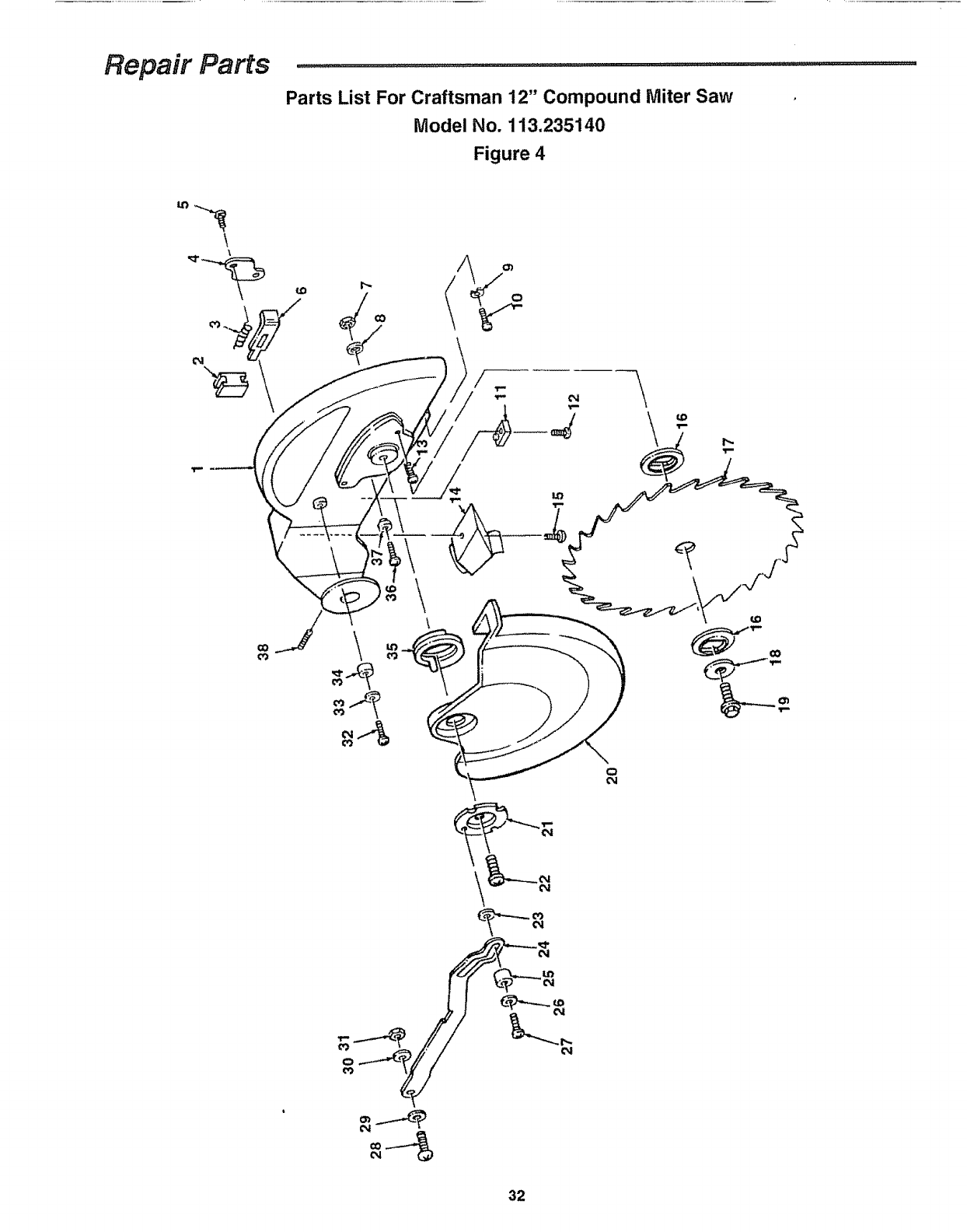
Repair Parts ........................... ............... ......................................................
Parts List For Craftsman 12" Compound Miter Saw
Model No. 113.235140
Figure 4
\\
o0
o_
04
32
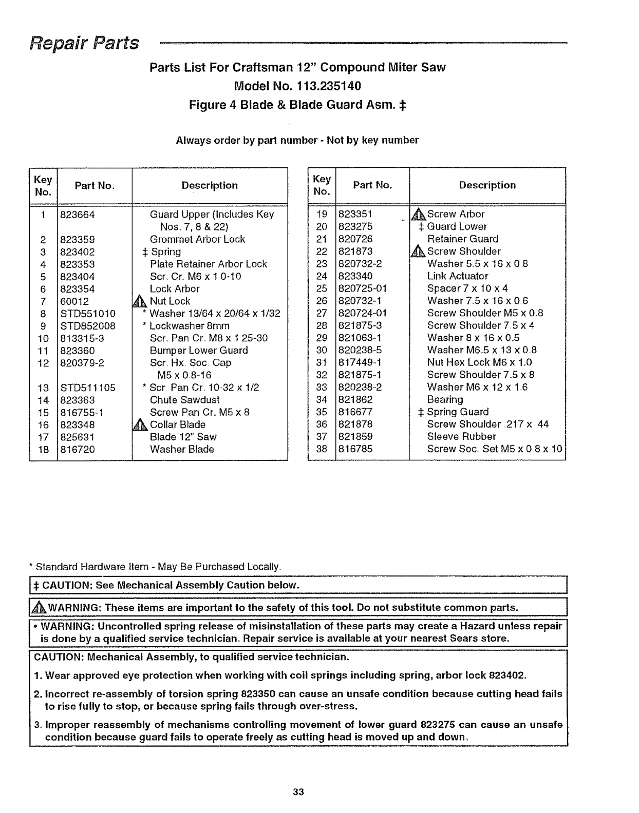
Repair Parts
Parts List For Craftsman 12" Compound Miter Saw
Model No. 113.235140
Figure 4 Blade & Blade Guard Asm. :_
Always order by part number - Not by key number
Key Part No.
No.
1 823664
2 823359
3823402
4 823353
5 823404
6 823354
7 60012 _k
8 STD551010 *
9 STD852008 *
10 813315-3
11 823360
12 820379-2
13 STD511105 *
Description
Guard Upper (Includes Key
Nos. 7, 8 & 22)
Grommet Arbor Lock
Spring
Plate Retainer Arbor Lock
Scr. Cr.. M6 x 10_10
Lock Arbor
Nut Lock
Washer 13/64 x 20/64 x 1/32
Lockwasher 8ram
Scr_ Pan Cr.. M8 x 1 25-30
Bumper Lower Guard
Scr. Hx. Soc. Cap
M5 x 0,8-16
Scr Pan Cr. 10_32 x 1t2
14 823363
15 816755-1
16 823348
17 825631
18 816720
&
Chute Sawdust
Screw Pan Cr,, M5 x 8
Collar Blade
Blade 12" Saw
Washer Blade
Key
No, Part No, Description
19 823351
2O 823275
21 820726
22 821873
23 820732-2
24 823340
25 820725-01
26 820732-1
27 820724-01
28 821875-3
29 821063-1
30 820238-5
31 817449-1
32 821875-1
33 820238-2
34 821862
35 816677
36 821878
37 821859
38 816785
_Screw Arbor
Guard Lower
Retainer Guard
_ Screw Shoulder
Washer 5.,5 x 16 x 08
Link Actuator
Spacer 7 x 10 x 4
Washer 7.,5 x 16 x 06
Screw Shoulder M5 x 0.8
Screw Shoulder 75 x 4
Washer 8 x 16 x 0..5
Washer M65 x 13 x 0.,8
Nut Hex Lock M6 x 1..0
Screw Shoulder 7°5 x 8
Washer M6 x 12 x 1_,6
Bearing
:1:Spring Guard
Screw Shoulder 217 x ,44
Sleeve Rubber
Screw Soc, Set M5 x 08 x 10
* Standard Hardware Item - May Be Purchased Locally,
CAUTION: See Mechanical Assembly Caution below.
_kWARNING: These items are important to the safety of this tool. Do not substitute common parts.
oWARNING: Uncontrolled spring release of misinstallation of these parts may create a Hazard unless repair
is done by a qualified service technician. Repair service is available at your nearest Sears store.
CAUTION: Mechanical Assembly, to qualified service technician.
1. Wear approved eye protection when working with coil springs including spring, arbor lock 823402°
2. Incorrect re-assembly of torsion spring 823350 can cause an unsafe condition because cutting head fails
to rise fully to stop, or because spring fails through over-stress.
3oImproper reassembly of mechanisms controlling movement of lower guard 823275 can cause an unsafe
condition because guard fails to operate freely as cutting head is moved up and down.
33

Notes .........
34

Notes .........................................................
35
MODEL NO.
113.235140
The model number of your 12
inch Compound Miter Saw will
be found on a plate attached to
your saw, at the side of the Miter
Saw arm
When requesting service or
ordering parts, always provide
the following information:
oProduct Type
° Model Number
° Part Number
° Part Description
12 0NCH COMPOUND
ITER SAW
For the repair or replacement paris youneed
Call 7 am - 7 pm, 7 days a week
t ,.SO0-366-PART
(1-800-366-7278)
For in-homemajor brand repairservice
Call 24 hoursa day, 7 days a week
t =S00=4=REPAUR
(1-800-473-7247)
For the location of a
Sears RepairService Center in your area
Cali 24 hours a day, 7 days aweek
t =800-488= t 222
For information on purchasinga Sears
Maintenance Agreementor to inquire
about an existingAgreement
Call 9 am - 5 pm, Monday-Saturday
1.-800=82=1-6655
............... i,,,
J w m
America's Repair Specialists
............. J__......................................................... .,
Sears, Roebuck and Co., Hoffman Estates, IL. 60179 U.S.A.
Part No SP6008 Form No SP6008 Printed in USA 10/96
