Craftsman 113235300 User Manual 10 COMPOUND MITRE SAW Manuals And Guides L0804182
CRAFTSMAN Miter Saw Manual L0804182 CRAFTSMAN Miter Saw Owner's Manual, CRAFTSMAN Miter Saw installation guides
User Manual: Craftsman 113235300 113235300 CRAFTSMAN 10 COMPOUND MITRE SAW - Manuals and Guides View the owners manual for your CRAFTSMAN 10 COMPOUND MITRE SAW #113235300. Home:Tool Parts:Craftsman Parts:Craftsman 10 COMPOUND MITRE SAW Manual
Open the PDF directly: View PDF ![]() .
.
Page Count: 36
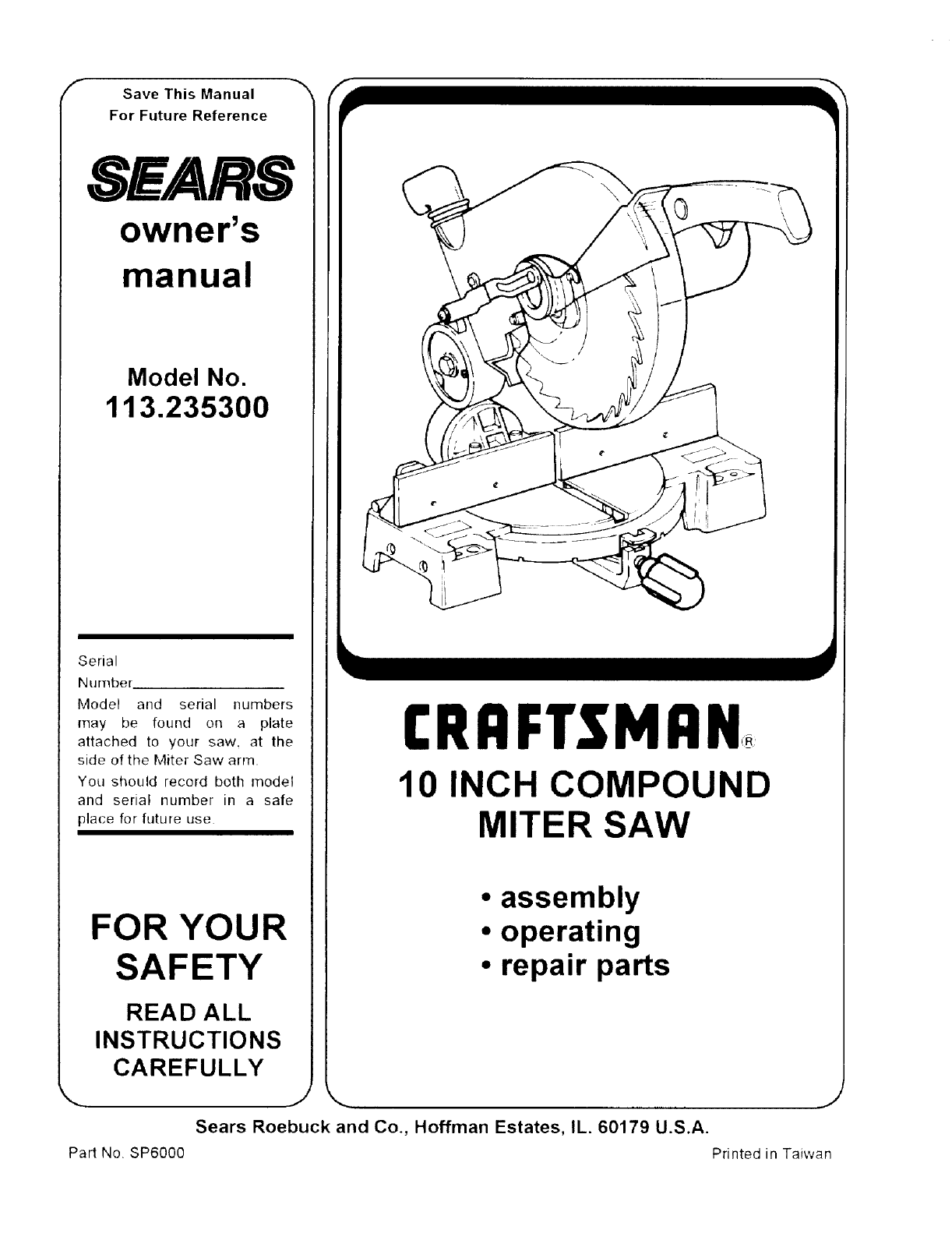
_- Save This Manual _'_
For Future Reference
SWARS
owner's
manual
Model No.
113.235300
Serial
Number
Model and serial numbers
may be found on a plate
attached to your saw, at the
side of the Miter Saw arrn.
You should record both model
and serial number in a sate
place for future use
FOR YOUR
SAFETY
READ ALL
INSTRUCTIONS
CAREFULLY
Pad No. SP6000
CRi:IFT$1qi:lN
10 INCH COMPOUND
MITER SAW
• assembly
• operating
• repair parts
Sears Roebuck and Co., Hoffman Estates, IL. 60179 U.S.A.
J
Printed in Taiwan
FULL ONE YEAR WARRANTY ON CRAFTSMAN BENCH TOP TOOLS
If this miter saw fails due to a defect in materia! or workmanship within one year from the date of pur-
chase, RETURN IT TO THE NEAREST SEARS SERVICE CENTER IN THE UNITED STATES, and Sears
will repair it, free of charge.
If this miter saw is used for commercial or rental purposes, this warranty will apply for ninety days
from the date of purchase.
This warranty applies only while this product is in the United States.
This warranty gives you specific legal rights, and you may also have other rights which vary from
state to state.
Sears, Roebuck and Co., D/817 Wa Hoffman Estates, IL 60179
Safety Instructions For Miter Saw
Safety is a combination of common sense, staying alert and knowing how your miter saw works. Read this manual to
understand this miter saw
Safety Signal Words
DANGER: means if the safety information is not followed
someone will be seriously injured or killed.
WARNING: means if the safety information ts not fol-
lowed someone could be seriously injured or killed.
CAUTION: means it the safety information is not followed
someone might be iniured.
Before Using The Saw
WARNING: to avoid mistakes that could cause
serious, permanent injury, do not plug the miter
saw in until the following steps have been satisfac-
torily completed.
• Assembly and alignment (See "Alignment!Adjustment"
section )
• Learn the use and function of the ON-OFF switch,
upper and lower blade guards, handle latch, bevel
clamp, cover plate stop screw, and fence clamps. (See
"Getting to Know Your Miter Saw" section.)
• Review and understand all safety instructions and
operating procedures in this manual
• Review the maintenance methods for this miter saw
(See 'Maintenance and Lubrication" section.)
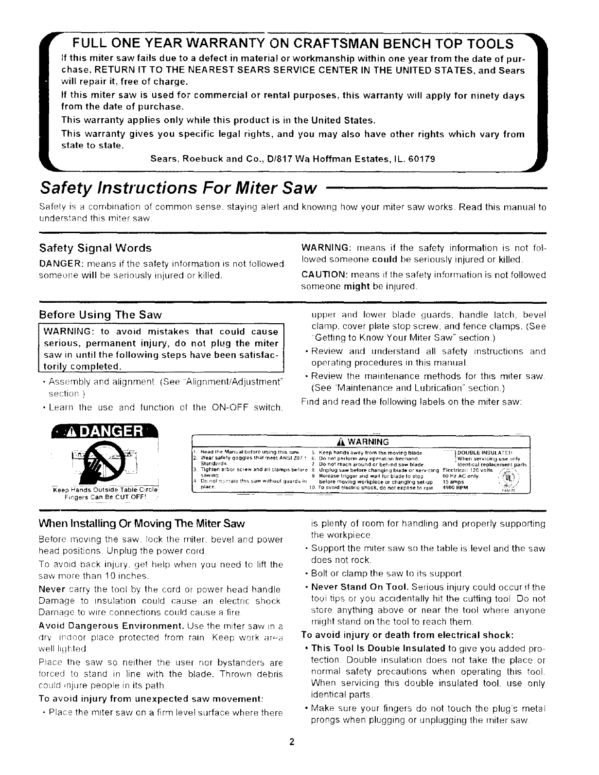
Find and read the following labels on the miter saw:
Keep Hancls Outside Table Cflrcle:_
Fingers Can Be CUT OFF! ,
_, WARNING
Read the Manual before u._ing this sa'# 5 Kf-ep hancl_ away lro_ the moVll_g blade I DOUBLE INSULATED
Wear safety qoClgles that rn_et ANSI Z8 t1 6 DO hal p_lerm any np_'ralir}n freehand I When serv}ci_g use ,_nly
Stand_Id_ 7 Do no! reach a_ound or behind saw blade II_¢l!_tc_l _replacemel_t parts
TIg_qle_ arbor screw and all clamps b_fore 8 Ui}plug _,aw befor_ changincI blacie or serv,circl _lec'trIca_: 120 vr}lts
_,aw_ng 9 Fleiease triggsr and wai! for blade 1o s_cp 60 H2 AC only
Do no! o_,u ale this saw wllhoul cluards in be!o_e movir_ a workpiece el changing _e_-up 15 ar_ps
_lace 10 TO 8void electric shock, do not expose t_ rain 4980 RPM _'o_f
When Installing Or Moving The Miter Saw
Before moving the saw lock the miter bevel and power
head positions Unplug the powerco_d
To avoid back injury, get help when you need to lift the
saw more than 10 inches
Never carry the tool by the cord or power head handle
Damage to insulation could cause an electric shock
Damage to wire connections could cause a fi_e
Avoid Dangerous Environment. Use the miter saw m
dry Indoor place protected from rain Keep work a_-a
we!l Iigt-,ted
Place the saw so neither the user nor bystanders are
torced to stand in line with the blade. Thrown debris
COhl]dinjure people in its path
To avoid injury from unexpected saw movement:
•Place the miter saw on a firnq level surface where there
is plenty of room for handling and properly supporting
the workpiece
• Support the miter saw so the table is level and the saw
does not rock.
• Bolt or clamp the saw to its supped
• Never Stand On Tool. Serious injury could occur if the
tooitips or you accidentally hit the cutting tool Do not
store anything above or near the tool where anyone
might stand on the tool to reach them.
To avoid injury or death from electrical shock:
• This Tool Is Double Insulated to give you added pro-
tection Double insulation does not take the place or
normal safety precautions when operating this tool
When servicing this double insulated tool, use only
identical parts,
• Make sure your fingers do not touch the plug's metal
prongs when plugging or unplugging the miter saw
Before Each Use
Inspect your miter saw.
Disconnect The Miter Saw To avoid injury from acci
dental starting, unplug the saw, before changing the
setup, changing the blade or adjusting anything
Compare [he direction of rotation arrow on the guard to
the direction arrow on the blade. The blade teeth should
always point downward at the front of the saw.
Tighten the arbor screw
Tighten tile cover plate stop screw
Check Damaged Parts. Check for:
Alignment of moving parts,
Damaged electric cords,
Binding of moving parts,
Broken parts.
Stable mounting,
Function of arm return spring and lower guard: Push
the aim all the way down then let _t rise up unti! it
stops by itself Check the lower guard to see if tclosed
fully If it did not. follow the instructions in the Trouble
Shooting section
• Other conditions that may affect the way the miter saw
works
Keep Guards In Place In working order and in proper
adjustment
If any partofthis miter saw is missing bent. or brokenm
any way, or any electrical parts don't work turn the saw
off and unplug it. Replace damaged missing _r failed
parts before using the saw again
Maintain Tools With Care. Keep the miter saw clesn for
best and safest performance Follow instructions for lubn
cating. DON'T put lubricants on the blade while it's spin
ning
Remove Adjusting Keys And Wrenches fr)m tool
before turning it on
To Avoid Injury From Jams, Slips Or Thrown
• Use Only Recommended Accessories. (See "Sears
Recommends The Following Accessories" section)
Consult this Owner's manual for recorT)rT)er;ded acces
series. Follow the instructions that come with the
accessories The use of improper accessories may
cause risk of injury to persons
• Choose the right !0-inch diameter blade for the mate+
rial and the type of cutting you plan to do
• Make sure the [)lade is sharp undamaged and prop
erly aligned. With the saw unplugged, push the power
head all the way down. Hand spin the blade and check
for clearance Tilt the power-head to 45 degree bevel
and repeat the check If the blade Mts anything, make
the adjustments shown in the Maintaining Maximt.m
Pieces
Cutting Capacity section
• Make sure the blade and arbor coltam ale clean
• Make sure the collars' recessed sides are fa;ing the
blade
• Using 1/2-inch box end wrench make sure the arbor
cap screw is firrnly t',and tightened
• Make sure all clamps and locks are t_ght and there _s
no excessive play m any pads
• Keep Work Area Clean. Cluttered areas and bencher_
invite accidents Floor must not beslippen/
To avoid burns or other tim damage never use the saw
near flammable[[quids vapors(rl gases
Plan Ahead To Protect Your Eyes, Hands, Face, Ears
Know Your Miter Saw. Read and understand the
owner's manual and labels affixed to the tool Learn its
application and limitations as well as the specific poten-
tial hazards peculiar to this tool
To avoid injury from accidental contact with rnoving parts.
dent do layout, assembly, or setup work on the miter saw
while any parts are moving
Avoid Accidental Starting. Make sure switch is "OFF"
before plugging miter saw into a power outlet
Plan your work.
Use The Right Tool. Dont force tool or attachment to do
a jot) it was not designed to do Use a different tool for
any workpiece that cant be held in a solidly braced, fixed
_osition
CAUTION: This machine is not designed for cut-
ting ferrous metals (steel, iron and iron based met-
als}. Use this miler saw to cut only wood, wood like
products or soft metals like aluminum. Other mate-
rial may shatter, bind on the blade, or create other
dangers.
CAUTION: When cutting any metals, sparks or hot
fragments could cause afire. To avoid this. dis-
connect any dust collecting hose from the miter
saw, and remove all traces of wood dust from
inside dust traps in the miter saw.
Dress for safety
f
i WEAR Y,'3U R
Any power miter saw can throw foreign objects into tne
eyes This car! result in permanent eye damage Wear
safely goggles (not glasses) that comply with ANS! Z87 1
(shown on package) Everyday eyeglasses have only
impact resistant lenses They are not safety glasses
Safety goggles are available at Sears retail stores
Glasses or goggles not in compliance with ANSI Z87
could seriously hurt you when they break
Safety Instructions For Miter Saw (continued)
• Do not wear loose clothing, gloves, neckties or jewelry
(rings, wrist watches) They can get caught and draw
you into moving parts
• Wear nonslip footwear.
• Tie back long hair.
• Roll long sleeves above the elbow
• Noise levels vary widely. To avoid possible hearing
damage, wear ear plugs or muffs when using miter
saw for hours at a time.
• For dusty operations, wear a dust mask along with
safety goggles.
Inspect Your Workpiece
• Make sure there are no nails or foreign objects in the
part of the workpiece to be cut.
Plan your work to avoid THROWBACKS - when the
workpiece binds on the blade and is torn from your
hands.
Plan the way you will hold tile workpiece from start to fin-
ish:
Avoid .awkward operations and hand positions where a
sudden slip could cause fingers or hand to move into the
blade
Don't Overreach. Keep good footing and balance
Keep your face and body to one side, out of line with a
possible throwback.
Never cut Freehand:
• Cut only one workpiece at a time
• Brace your workpiece solidly against the fence and
table lop so it will not rock or twist during the cut
• Make sure there's no debris between the workpiece
and its supports
• Make sure no gaps between the workpiece, fence and
table will let the workpiece shift after it is cut in two.
• Keep the cut off piece free to move sideways after it's
cut oft. Otherwise, it could get wedged against the
blade and thrown violently
• Clear everything except the workpiece and related
support devices off the table before turning the miter
SaW on.
• Secure Work. Use clamps or a vise to help hold the
work when it's practical.
Use extra caution with large, very small or awkward
workpieces:
• Use extra supports (tables, saw horses, blocks, etc.)
for any workpieces large enough to tip when not held
down to the table top.
• Never use another person as a substitute for a table
extension, or as additional support for a workpiece that
is longer or wider than the basic miter saw table or to
help feed, support or pull the workpiece.
• Do not use this saw to cut pieces too small to let you
easily hold the work while you keep the thumb side of
your index (pointer) finger against the outside edge of
the fence.
• When cutting irregularly shaped workpieces, plan your
work so it will not slip and pinch the blade and be torn
from your hands. A piece of molding, for example,
must lie flat or be held by a fixture or jig that will not let
it twist, rock or slip while being cut.
• Properly support round material such as dowel rods. or
tubing. They have a tendency to roll while being cut.
causing the blade to "bite." To avoid this. always use a
fixture designed to properly hold your workpiece.
WARNING: If planning to cut aluminum or other
non-ferrous metals: Under adverse conditions, the
blade can grab and throw the workpiece suddenly
and unexpectedly. To avoid injury, follow all appli-
cable safety instructions, as you normally would,
and:
• Use only sawblades specifically recommended
for non-ferrous metal cutting.
• Do not cut metal workpieces that must be hand
held. Use auxiliary clamps or other equipment as
needed.
• Cut non-ferrous metals only if you are experi-
enced or under the supervision of an experienced
person.
Whenever Saw Is Running
WARNING: don't allow familiarity (gained from fre-
quent use of your miter saw) cause a careless mis-
take. A careless fraction of a second is enough to
cause a severe injury.
Before starting your cut, watch the miter saw while it
runs. If it makes an unfamiliar noise or vibrates a lot, stop
immediately Turn the saw off Unplug the saw. Do not
restart until finding and correcting the problem.
Keep Children Away Keep all visitors a safe distance
from the miter saw. Make sure bystanders are clea_ of
the miter saw and workpiece
Never confine the piece being cut off. Never hold it
clamp it, touch it, or use length stops against it while the
blade is spinnmg. It must be free to move sideways on its
own. If confined, it could get wedged against the blade
and thrown violently.
Let the blade reach full speed before cutting.
Don't Force Tool. It will do the job better and safer at its
designed rate, Feed the saw into the workpiece only fast
enough to let the blade cut without bogging down or binding
Before freeing jammed material:
•Turn switch "OFF"
•Unplug the miter saw.
•Wait for all moving parts to stop.
After finishing a cut:
•Keep holding the power head down
•Release the switch, and wait for all moving parts to
stop before moving your hands
• If blade doesn't stop within 6 seconds, unplug the saw
and follow the instructions in the Trouble Shooting sec-
tion for fixing the blade brake before using the saw
again.
Before Leaving The Saw
Never Leave Tool Running Unattended.Turn power Make workshop child-proof. Lock the shop Disconnect
off Wait for all moving parts to stop. master switches Store tool away from children and oth-
ers not qualified to use the tool.
Glossary of Terms for Woodworking
Arbor
The shaft on which a cutting tool is mounted
Bevel Cut
An angle cutting operation made through the face of the
workpiece.
Compound Cut
A simultaneous bevel and miter cutting operation
Crosscut
A cutting operation made across the width of the work
piece.
Freehand
Performing a cut without the use of fence (guide), hold
down or other proper device to prevent the workpiece
from twisting during the cutting operation. Twisting of the
workpiece can cause it to be thrown
Gum
A sticky, sap based residue frorn wood products.
Heel
Misalignment of the blade
Kerr
The amount of material removed by the blade in a
through cut or the slot produced by the blade in a non-
through or partial cut.
Miter Cut
An angle cutting operation made across the width of the
workpiece.
Resin
A sticky, sap based substance that has hardened.
Revolutions Per Minute (RPM)
The number of turns completed by a spinning object in
one minute.
Sawblade Path
The area of the workpiece or table top directly in line with
either the travel of the blade or the part of the workpiece
which will be, or has been, cut by the blade.
Set
The distance that the tip of the sawblade tooth is bent (or
set) outward from the face of the blade
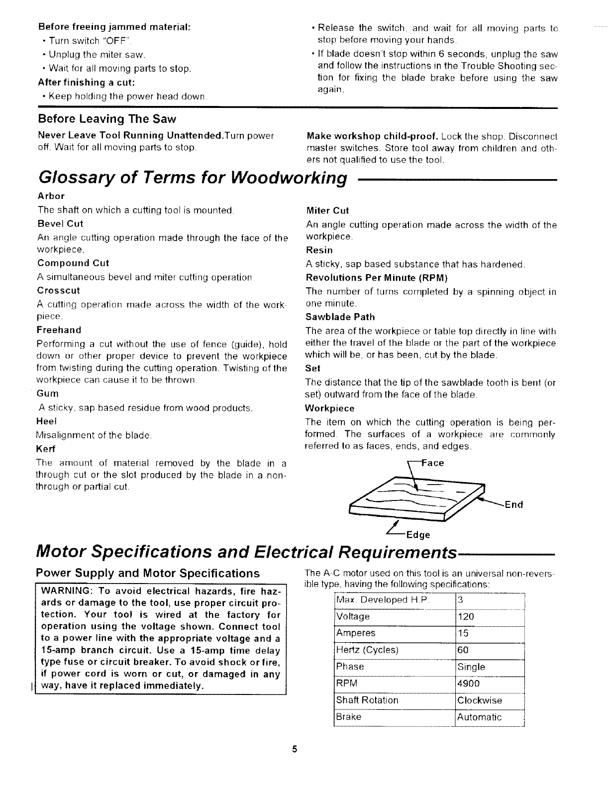
Workpiece
The item on which the cutting operation is being per-
formed The surfaces of a workpiece are commonly
referred to as faces, ends, and edges.
End
Z_--Edge
Motor Specifications and Electrical Requirements
Power Supply and Motor Specifications The A C motor used on this tool is an universal non-revers
ible type, having the following specifications:
WARNING: To avoid electrical hazards, fire haz- Max Developed HP 3
ards or damage to the tool, use proper circuit pro-
tection. Your tool is wired at the factory for Voltage 120
operation using the voltage shown. Connect tool
to a power line with the appropriate voltage and a Amperes 15
15-amp branch circuit. Use a 15-amp time delay Hertz (Cycles) 60
type fuse or circuit breaker. To avoid shock or fire, Phase Single
if power cord is worn or cut, or damaged in any
! way, have it replaced immediately. RPM 4900
Shaft Rotation Clockwise
Brake Automatic
Motor Specifications and Electrical Requirements (continued)
General Electrical Connections
DANGER: To avoid electrocution:
1. Use only identical replacement parts when ser-
vicing. Servicing should be performed by a
qualified service technician.
2. Do not use in rain or where floor is wet.
This tool is intended for indoor residential use
only.
WARNING Do not permit fingers to touch the ter-
minals of plug when installing or removing the
plug to or from the outlet. I
If power cord is worn or cut, or damaged in any way
have it replaced immediately
110-120 Volt, 60 Hz. Tool Information
Double Insulated
The miter saw is double insulated to provide a double
thickness of insulation between you and the tool's electri-
cal system. All exposed metal parts are isolated from the
internal metal motor components with protectin_j insula
tion
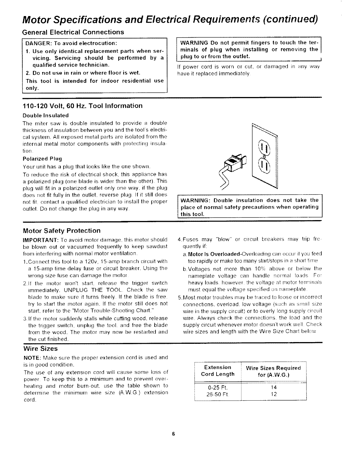
Polarized Plug
Your unit has a plug that looks like the one shown.
To reduce the risk of electrical shock, this appliance has
a polarized plug (one blade is wider than the other). This
plug will fit in a polarized outlet only one way. if the plug
does not fit fully in the outlet, reverse plug If it still does
not fit contact a qualified electrician to install the proper
outlet. Do not change the plug in any way
I
WARNING: Double insulation does not take the I
place of normal safety precautions when operating I
this tool.
Motor Safety Protection
IMPORTANT: To avoid motor damage, this motor should
be blown out or vacuumed frequently to keep sawdust
flora interfering with normal motor ventilation.
1.Connect this tool to a 120v, 15-amp branch circuit with
a 15-amp time delay fuse or circuit breaker. Using the
wrong size fuse can damage the motor
2 If the motor won't starL release the trigger switch
immediately. UNPLUG THE TOOL. Check the saw
blade to make sure it turns freely. If the blade is free.
try to start the motor again. If the motor still does not
start, refer to the "Motor Trouble-Shooting Chart."
3 If the motor suddenly stalls while cutting wood, release
the trigger switch, unphlg the tool. and free the blade
from the wood. The motor may now be lestarted and
the cut finished.
Wire Sizes
NOTE: Make sure the proper extension cord is used and
is in good condition.
The use of any extension cord will cause some loss of
power To keep this to a minimum and to prevent over-
heating and motor burn-out, use the table shown to
determine the minimum wire size (AW.G) extension
cord.
4.Fuses may "blow" or circuit breakers may trip fro
quently if:
a. Motor Is Overloaded-Overloading can occur il you feed
too rapidly or make too many staWstops in a short time
b.Voltages not more than 10% above or below the
nameplate voltage can handle normal loads For
heavy loads howeve_ the voltage at motor terminals
must equal the voltage speciiled on nameplate
5.Most motor troubles may be traced to loose or incorrect
connections, overload, low voltage (su(h as small size
wire in the supply circuit) or to overly long supply circuit
wire, Always check the connections, the load and the
supply circuit whenever motor doesn't work wetl Check
wire sizes and length with the Wire Size Chart bel_!w
Extension Wire Sizes Required
i Cord Length for (A.W.G.)
!
iO-25 Ft. 14
26-5O Ft 12
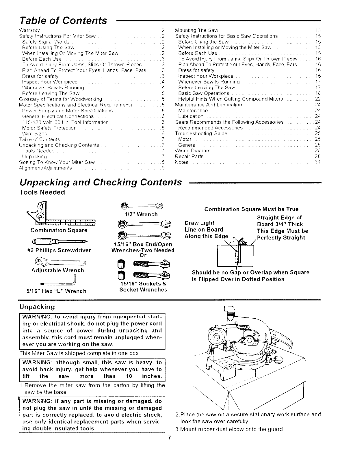
Table of Contents
'v%'arr a n[y
Safety "st',_cttuns Fur M_ter 5a_',
Safety S!gnal Words
Before Us ng The Saw
When nsta nng Dr Mov nc Tr'e Miter 3a',_
Before Each use
ToAvod n)u% From Jams ShusOr Thrown Pieces
Plan Ahead To PrntectYou rEdes manr_s Face Ears
Dress for safet,
I_spect ¢OLlr Workoqece
Whenever Saw s _tmning
Be'ore eav ng The Raw
G ossary cf Terms for Woodworking
Motor Specifications ano Electrical ae(]dlremenfs
Powe _ S.@piy and Motcr SDectflcatlcns
General Electrical Connections
119-!2C Volt 60 m/ -oo rfforrratlon
Mater Satety Protection
Wre Szes
mabie of Contents
Unpack "g anu 2heck no Contepts
Too s Needed
Unpacking
Getling To Know four Mite r Saw
Ahgnme_t/Adj_,sTme n:s
2 Mounhng The Saw ........... 13
2 Safety' Instructions for Basic Saw Operations 15
2 Before Using the Saw ................ 15
2 When !nstalling or Moving the Miter Saw !5
2 Before Each Use .................... 15
3 To Avold lnjury From Jams Slips Or Thrown Pieces .... 16
3 P an Ahead To Protect Your Eyes Hands. Face. Ears 16
3 Dress for safety 16
3 Inspect Your Workpiece 16
_1 Whenever Saw Is Running 17
4 Before Leaving The Saw !7
5 Basic Saw Operahons ........... 18
5 He pful Hints When CuEing Compound Miters .... 22
5 Maintenance And Lubrication ...... 24
Maintenance .......... 24
6 Lubncation .................... 24
6 Sears Recommends the Following Accesso;les . 24
6 Recommended Accessones ........... 24
6 TroubIeshootmg Guide .......... 25
7 Motor ........... 25
7 General ......... 25
7 VVinng Diagram 26
Repatr Darts 28
Notes 34
Unpacking and Checking Contents
Tools Needed
q::i:il:', 3:',i:i;;J;I
Combination Square
#2 Phillips Screwdriver
Adjustable Wrench
5/16" Hex "L" Wrench
1/2" Wrench
15116" Box End/Open
Wrenches-Two Needed
Or
15t16" Sockets &
Socket Wrenches
Combination Square Must be True
Straight Edge of
Draw Light Board 3/4" Thick
Line on Board This Edge Must be
Along this Edge _,, Perfectly Straight
Should be no Gap or Overlap when Square
is Flipped Over in Dotted Position
Unpacking
WARNING: to avoid injury from unexpected start-
ing or electrical shock, do not plug the power cord
into a source of power during unpacking and
assembly, this cord must remain unplugged when-
ever you are working on the saw.
This Miter Saw is shipped complete in one box
I WARNING: although small, this saw is heavy, to I
avoid back injury, get help whenever you have to I
lift the saw more than 10 inches.
1Remove the miter saw from the carton by lifting the
saw by the base
WARNING: if any part is missing or damaged, do
not plug the saw in until the missing or damaged
part is correctly replaced, to avoid electric shock,
use only identical replacement parts when servic-
ing double insulated tools.
\\.
2.Place the saw on a secure stationary work surface and
look the saw over carefully.
3.Mount rubber dust elbow onto the guard
Getting To Know Your Miter Saw
Elbow Upper Blade
Guard Lock Off
Button
\\
7Miter Saw
/Handle
/
1 Warning
Label
Switch
;) Handle
Latch
Fence
Miter Scale 4Miter Lock
Handle Power Cord 3Fence Lock 5Bevel Lock
Handle Handle
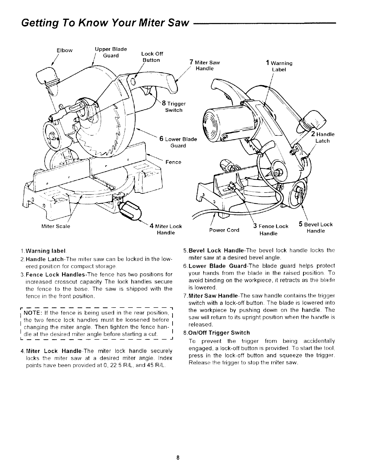
1.Warning label
2.Handle Latch-The miter saw can be locked in the low-
ered position for compact storage
3 Fence Lock Handles-The fence has two positions for
increased crosscut capacity The lock handles secure
the fence to the base. The saw is shipped with the
fence in the front position.
t" "1
I NOTE: If the fence is being used in the rear position, I
the two fence lock handles must be loosened before
Ichanging the miter angle. Then tighten the fence han-
Idie at the desired miter angle before starting a cut.
L. J
4. Miter Lock Handle The miter lock handle securely
locks the miter saw at a desired miter angle. Index
points have been provided at 0.22 5 R/L, and 45 R/L.
5.Bevel Lock Handle-The bevel lock handle locks the
miter saw at a desired bevel angle
6.Lower Blade Guard-The blade guard helps protect
your hands from the blade in the raised position To
avoid binding on the workpiece, it retracts as the blade
is lowered.
7.Miter Saw Handle-The saw handle contains the trigge_
switch with a lock-off button. The blade is lowered into
the workpiece by pushing down on the handle, The
saw will return to its upright position when the handle is
I released.
I 8.OntOff Trigger Switch
To prevent the trigger from being accidentally
engaged, a lock-off button is provided. To start the tool,
press in the lock-off button and squeeze the trigger.
Release the trigger to stop the miter saw.
Alignment/Adjustments
WARNING: To avoid injury from unexpected start-
ing or electrical shock, do not plug the saw in. The
power cord must remain unplugged whenever you
are working on the saw.
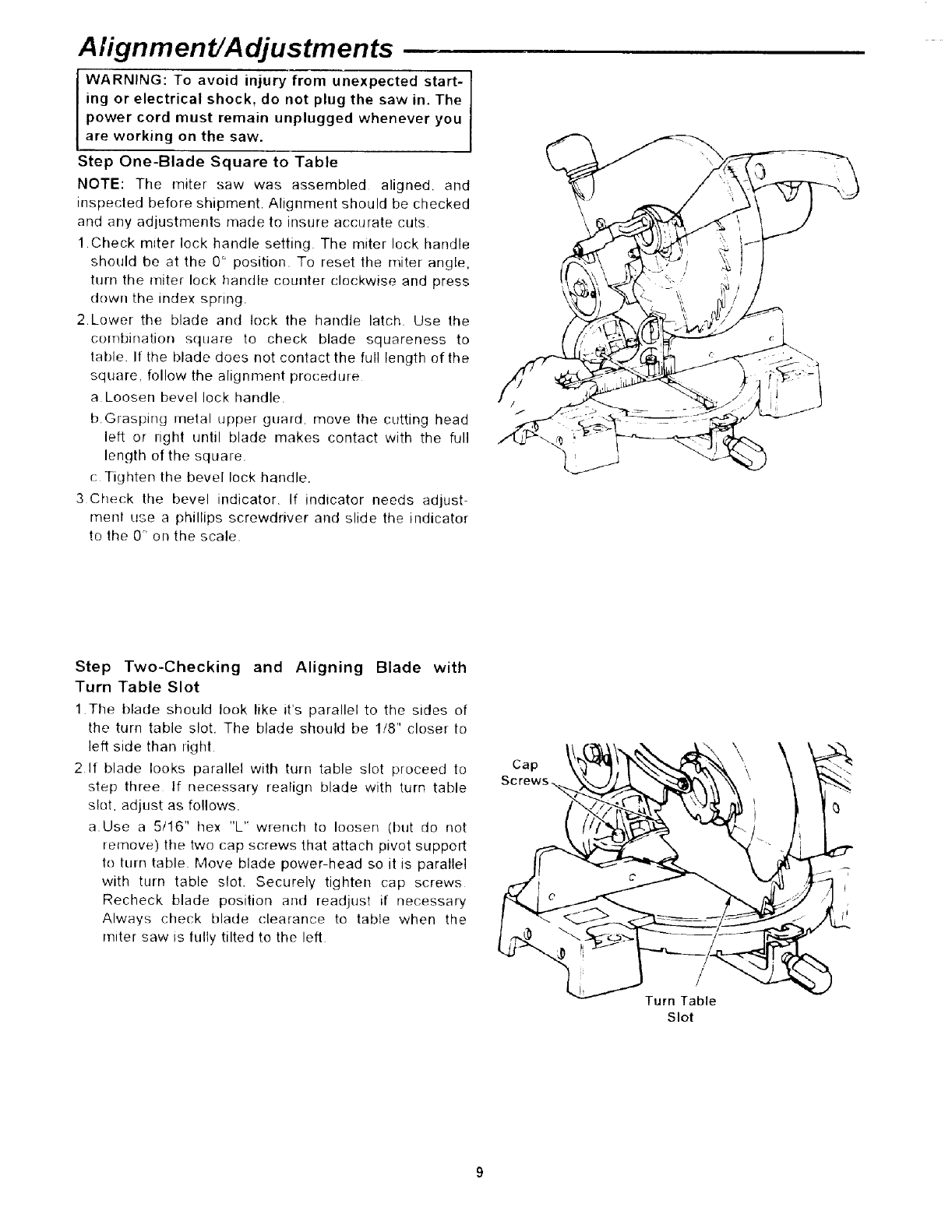
Step One-Blade Square to Table
NOTE: The miter saw was assembled aligned, and
irrspected before shipment. Alignment should be checked
and any adjustments made to insure accurate cuts.
1Check miter lock handle setting. The miter lock handle
should be at the 0' position. To reset the miter angle,
turn the miter lock handle counter clockwise and press
down the index spring.
2.Lower the blade and lock the handle latch Use the
combirlation square to check blade squareness to
table. It the blade does not contact the full length of the
square, follow the alignment procedure
a Loosen bevel lock handle.
b.Grasping metal upper guard, move the cutting head
left or right until blade makes contact with the full
length of the square
{: Tighten the bevel lock handle.
3 Check the bevel indicator. If indicator needs adjust-
menl use a phillips screwdriver and slide the indicator
to the 0" on the scale,
Step Two-Checking and Aligning Blade with
Turn Table Slot
1 The blade should took like it's parallel to the sides of
the turn table slot. The blade should be 1/8" closer to
left side than right
2If blade looks parallel with turn table slot proceed to
step three If necessary realign blade with turn table
slot, adjust as follows.
a. Use a 5/16" hex "L" wrench to loosen (but do not
remove) the two cap screws that attach pivot support
to turn table Move blade power head so it is parallel
with turn table slot. Securely tighten cap screws
Recheck blade position and readjust if necessary
Always check blade clearance to table when the
miter saw is tully tilted to the left
Cap
/
Turn Table
Slot
\\
Alignment/Adjustments (continued)
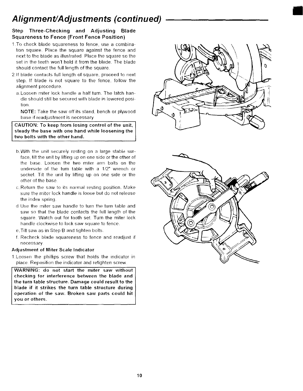
Step Three-Checking and Adjusting Blade
Squareness to Fence (Front Fence Position)
1 To check blade squareness to fence, use a combina-
tion square. Place the square against the fence and
next to the blade as illustrated Place the square so the
set in the teeth won't hold it from the blade. The blade
should contact the full length of the square.
2.If blade contacts full length of square, proceed to next
step, If blade is not square to the fence, follow the
alignment procedure.
a,Loosen miter lock handle a half turn. The latch han-
dle should still be secured with blade in lowered posi
tion.
NOTE: Take the saw off its stand, bench or plywood
base if readjustment is necessary
CAUTION: To keep from losing control of the unit,
steady the base with one hand while loosening the
two bolts with the other hand.
b.With the unit securely resting on a large stable sur-
face, tilt the unit by lifting up on one side or the other of
the base. Loosen the two miter arm bolts on the
underside of the turn table with a 1/2" wrench or
socket Tilt the unit by lifting up on one side or the
other of the base
c. Return the saw to its normal resting position. Make
sure the miter lock handle is loose but do not release
the index spring.
d Use the miter saw handle to turn the turn table and
saw so that the blade contacts the full length of the
square. Watch out for tooth set. Turn the miter lock
handle clockwise to lock saw square to fence.
e.Tilt saw as in Step B and tighten bolts.
f. Recheck blade squareness to fence and readjust if
necessary
Adjustment of Miter Scale Indicator
1 Loosen the phillips screw that holds the indicator in
place Reposition the indicator and retighten screw
WARNING: do not start the miter saw without
checking for interference between the blade and
the turn table structure. Damage could result to the
blade if it strikes the turn table structure during
operation of the saw. Broken saw parts could hit
you or others.
10
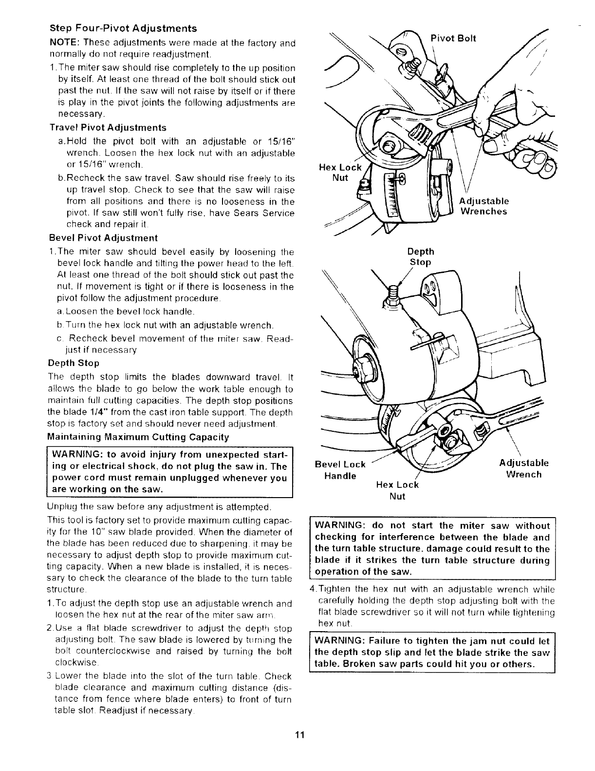
Step Four-Pivot Adjustments
NOTE: These adjustments were made at the factory and
normally do not require readjustment.
1 .The miter saw should rise completely to the up position
by itself. At least one thread of the bolt should stick out
past the nut. If the saw will not raise by itself or if there
is play in the pivot joints the following adjustments are
necessary.
Travel Pivot Adjustments
a,Hold the pivot bolt with an adjustable or 15/16"
wrench. Loosen the hex lock nut with an adjustable
or 15/16" wrench.
b.Recheck the saw travel. Saw should rise freely to its
up travel stop. Check to see that the saw will raise
from all positions and there is no looseness in the
pivot. If saw still won't fully rise. have Sears Service
check and repair it
Bevel Pivot Adjustment
1.The miter saw should bevel easily by loosening the
bevel lock handle and tilting the power head to the left.
At least one thread of the bolt should stick out past the
nut. If movement is tight or if there is looseness in the
pivot follow the adjustment procedure
a. Loosen the bevel lock handle.
b Turn the hex lock nut with an adjustable wrench.
c Recheck bevel movement of tile miter saw. Read-
just if necessary
Depth Stop
The depth stop limits the blades downward travel. It
allows the blade to go below the work table enough to
maintain full catting capacities. The depth stop positions
the blade 1/4" from the cast iron table support. The depth
stop is factory set and should never need adjustment
Maintaining Maximum Cutting Capacity
WARNING: to avoid injury from unexpected start-
ing or electrical shock, do not plug the saw in. The
power cord must remain unplugged whenever you
are working on the saw.
Unplug the saw before any adjustment is attempted.
This tool is factory set to provide maximum cutting capac-
ity for the 10" saw blade provided. When the diameter of
the blade has been reduced due to sharpening it may be
necessary to adjust depth stop to provide maximurn cut-
ting capacity. When a new blade is installed, it is neces
sary to check the clearance of the blade to the turn table
structure.
1.To adjust the depth stop use an adjustable wrench and
loosen the hex nut at the rear of the miter saw arm
2Use a fiat blade screwdriver to adjust the depth stop
adJusting bolt. The saw blade is lowered by turning the
bolt counterclockwise and raised by turning the bolt
clockwise.
3 Lower the blade into the slot of the turn table Check
blade clearance and maximum cutting distance (dis-
tance from fence where blade enters) to front of turn
table slot Readjust if necessary
Pivot Bolt
Hex Lock
Nut
Adjustable
Wrenches
\
\
\
Depth
Stop
\
Bevel Lock Adjustable
Handle Wrench
Hex Lock
Nut
WARNING: do not start the miter saw without
checking for interference between the blade and
the turn table structure, damage could result to the
blade it it strikes the turn table structure during
operation of the saw.
4.Tighten the hex nut with an adjustable wrench while
carefully holding the depth stop adjusting bolt with the
flat blade screwdriver so it will not turn while tighteni_lg
hex nut
I WARNING: Failure to tighten the jam nut could let I
the depth stop slip and let the blade strike the saw Itable. Broken saw parts could hit you or others.
11

Alignment/Adjustments (continued)
Fence Positions
The miter saw has two fence positions The front fence
position is used for workpieces up to standard 2 x 4 for
cut off and bevel operation, floor and ceiling moldings,
and door casings. The rear fence position is used for cut
off and bevel operation for a standard 2 x6 workpiece.
Standard 2 x 4 measures 1-1/2" x3-1/2"
Standard 2 x 6 measures 1 1/2" x 5-1/2"
The base on either side of the work table has two sets of
holes for locating the fence. To change the fence posi-
tion. remove the two fence lock handles. Put the fence in
the other fence position and install the fence lock han-
dles
The rear fence position is designed to slide side to side
when the miter setting is changed. This feature lets the
fence move to provide maximum support for the work-
piece. If it is necessary to change the miter cut in the rear
position, first loosen the fence lock handles. Release the
miter lock handle and move it to the desired miter angle
Tighten the miter lock handle and the fence lock handles.
IMPORTANT: Do not try to change the miter position
while the fence is in the rear fence position before loos-
ening the fence lock handles. You might damage the
fence alignment arm
Removing or Installing the Blade
I WARNING: To avoid injury from a thrown work-
piece or thrown pieces of blade, do not use ablade
larger or smaller than 10" diameter.
I WARNING: To avoid injury from unexpected start-
ing, unplug the saw whenever you are removing or
installing the blade.
1.Unplug the saw from the outlet.
2 Loosen the screw holding the lower guard mounting
plate to the upper guard with phillips screwdriver.
&Lift the lower guard up and tilt the lower guard assem
bly back so the arbor screw is exposed.
4Find tile arbor lock between the upper guard and the
miter saw handle Place a 1/2" box end wrench over
arbor screw.
5. Press the arbor lock and hold it in firmly while turning
the wrench clockwise. The arbor lock will engage after
some turnir_g of the wrench.
6 Remove the arbor screw, arbor washer, outer blade
collar and tile blade
NOTE: Pay attention to pieces removed, noting their
position and direction they face (see illustration), Wipe
the blade collars clean of any sawdust before installing
the new blades.
7 Install the new 10" blade (see recommended acces-
son/ list) Make sure the rotation arrow on the blade
matches the clockwise rotation arrow on the upper
gua[d
I
Front Fence Position
Rear Fence Position
!
|
Arbor_
Lock
UpperfJ
Blade
Guard
J ,m
T
/
Miter Saw
Handle
12
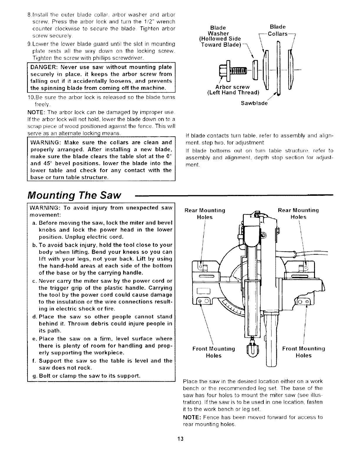
8.Install tile outer blade collar, arbor washer and arbor
screw Press the arbor lock and turn the 1/2" wrench
counter clockwise to secure the blade Tighten arbor
screw securely
9. Lower the lower blade guard until the slot in mounting
['late rests all the way down on the locking screw.
Tighten the screw with phillips screwdriver.
DANGER: Never use saw without mounting plate
securely in place, it keeps the arbor screw from
falling out if it accidentally loosens, and prevents
the spinning blade from coming off the machine.
10.Be sure the arbor lock is released so the blade turns
freely.
NOTE: The arbor lock can be damaged by improper use
If the arbor lock will net hold. lower the blade down on to a
s(:rap piece of wood positioned against the fence. This will
serve as an alternate locking means.
WARNING: Make sure the collars are clean and
properly arranged. After installing a new blade,
make sure the blade clears the table slot at the 0 °
and 45 °bevel positions, lower the blade into the
lower table and check for any contact with the
base or turn table structure.
Blade
Washer
(Hollowed Side
Toward Blade)-_ \
Arbor screw
(Left Hand Thread) _'
/
Sawb!ade
Blade
-- Collars---
If blade contacts turn table, refer to assembly and align-
merit, step two, for adjustment
If blade bottoms out on turn table structure, refer to
assembly and alignment, depth stop section for adjust-
ment.
Mounting The Saw
WARNING: To avoid injury from unexpected saw
movement:
a. Before moving the saw, lock the miter and bevel
knobs and lock the power head in the lower
position. Unplug electric cord.
b. To avoid back injury, hold the tool close to your
body when lifting. Bend your knees so you can
lift with your legs, not your back. Lift by using
the hand-hold areas at each side of the bottom
of the base or by the carrying handle.
c. Never carry the miter saw by the power cord or
the trigger grip of the plastic handle. Carrying
the tool by the power cord could cause damage
to the insulation or the wire connections result-
ing in electric shock or fire.
d. Place the saw so other people cannot stand
behind it. Thrown debris could injure people in
its path.
e. Place the saw on a firm, level surface where
there is plenty of room for handling and prop-
erly supporting the workpiece.
f. Support the saw so the table is level and the
saw does not rock.
g. Bolt or clamp the saw to its support.
Rear Mounting Rear Mounting
Holes Holes
\
Front Mounting
Holes Front Mounting
Holes
Place the saw in the desired location either on a work
bench or the recommended leg set. The base of the
saw has four holes to mount the miter saw (see illus
tration). If the saw is to be used in one location, fasten
it to the work bench or leg set.
NOTE: Fence has been moved forward for access to
rear mounting holes.
13
Mounting The Saw (continued)
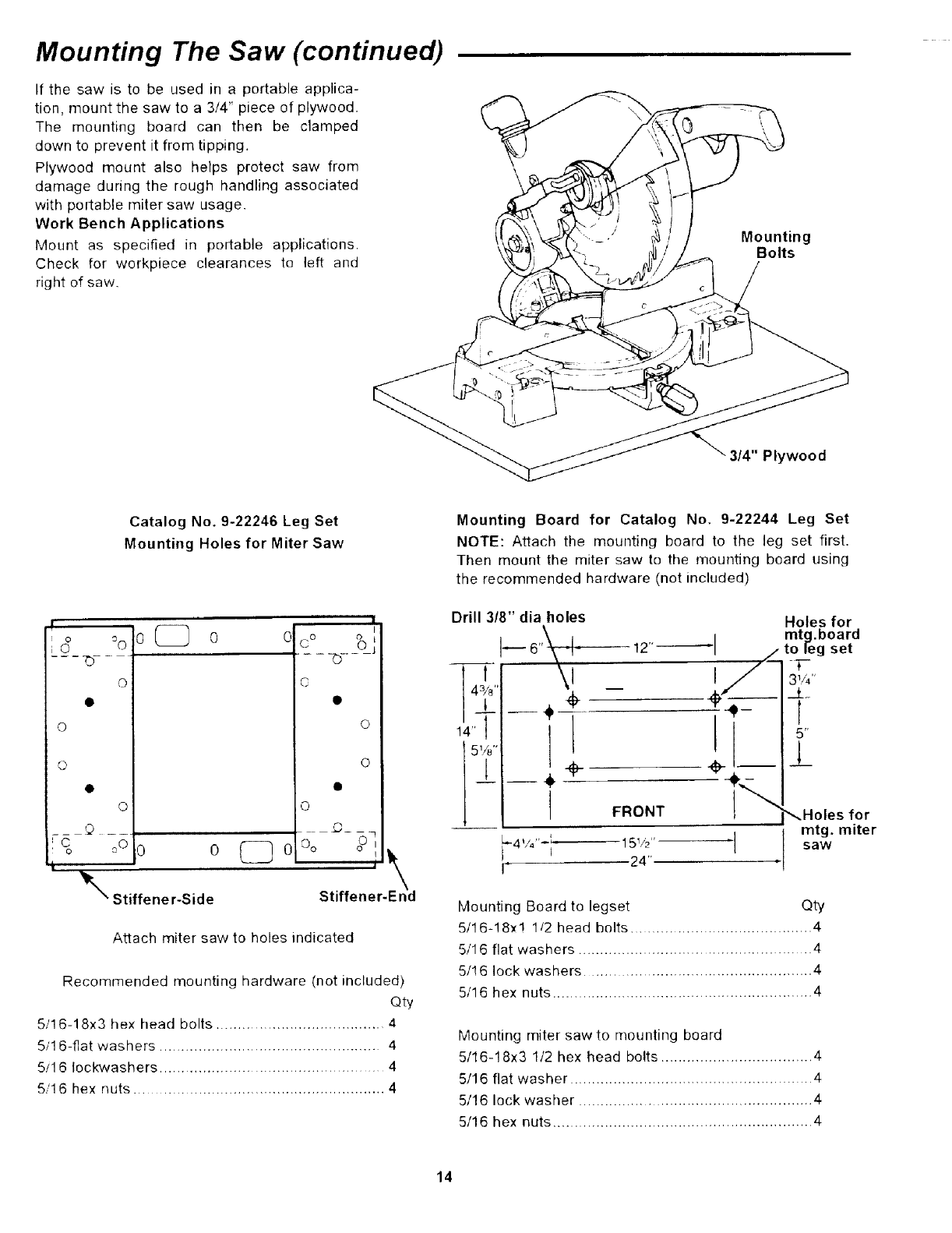
If the saw is to be used in a portable applica-
tion, mount the saw to a 3/4" piece of plywood.
The mounting board can then be clamped
down to prevent it from tipping.
Plywood mount also helps protect saw from
damage during the rough handling associated
with portable miter saw usage.
Work Bench Applications
Mount as specified in portable applications.
Check for workpiece clearances to left and
right of saw.
Mounting
Bolts
3/4" Plywood
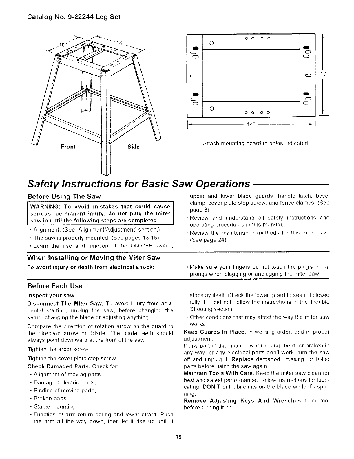
Catalog No. 9-22246 Leg Set
Mounting Holes for Miter Saw
o _0
0
,,0
0
C3
=0 ,_0
: o _ 0 0
i
_N" Stiffener-Side
[
°o°
©
o
o
Oo oo
Stiffener-End
Attach miter saw to holes indicated
Recommended mounting hardware (not included)
Qty
5/16-18x3 he× head bolts ....................................... 4
5/1 6-flat washers ................................................... 4
5/1 6 Iockwashers .................................................... 4
5/16 hex nuts ......................................................... 4
Mounting Board for Catalog No. 9-22244 Leg Set
NOTE: Attach the mounting board to the leg set first.
Then mount the miter saw to the mounting board using
the recommended hardware (not included)
Drill 3/8" dia holes
L
1÷
--i
FRONT
Holes for
mtg.board
12"_1 4 toleg set
÷
I J 3W'
i __ .....t__6"
J_
,L-4V4''-I- 151,'2'' "j
I t
I" 24"
_.Holes for
mtg. miter
saw
Mounting Board to legset Qty
5116-18×! 1/2 head bolts ........................................ 4
5/1 6 flat washers ...................................................... 4
5/!6 lock washers ................................................. 4
5116 hex nuts ............................................................ 4
Mounting miter saw to mounting board
5/16-18x3 1/2 hex head bolts ................................... 4
5/16 flat washer ........................................................ 4
5/16 lock washer ................................................... 4
5/16 hex nuts ............................................................ 4
14
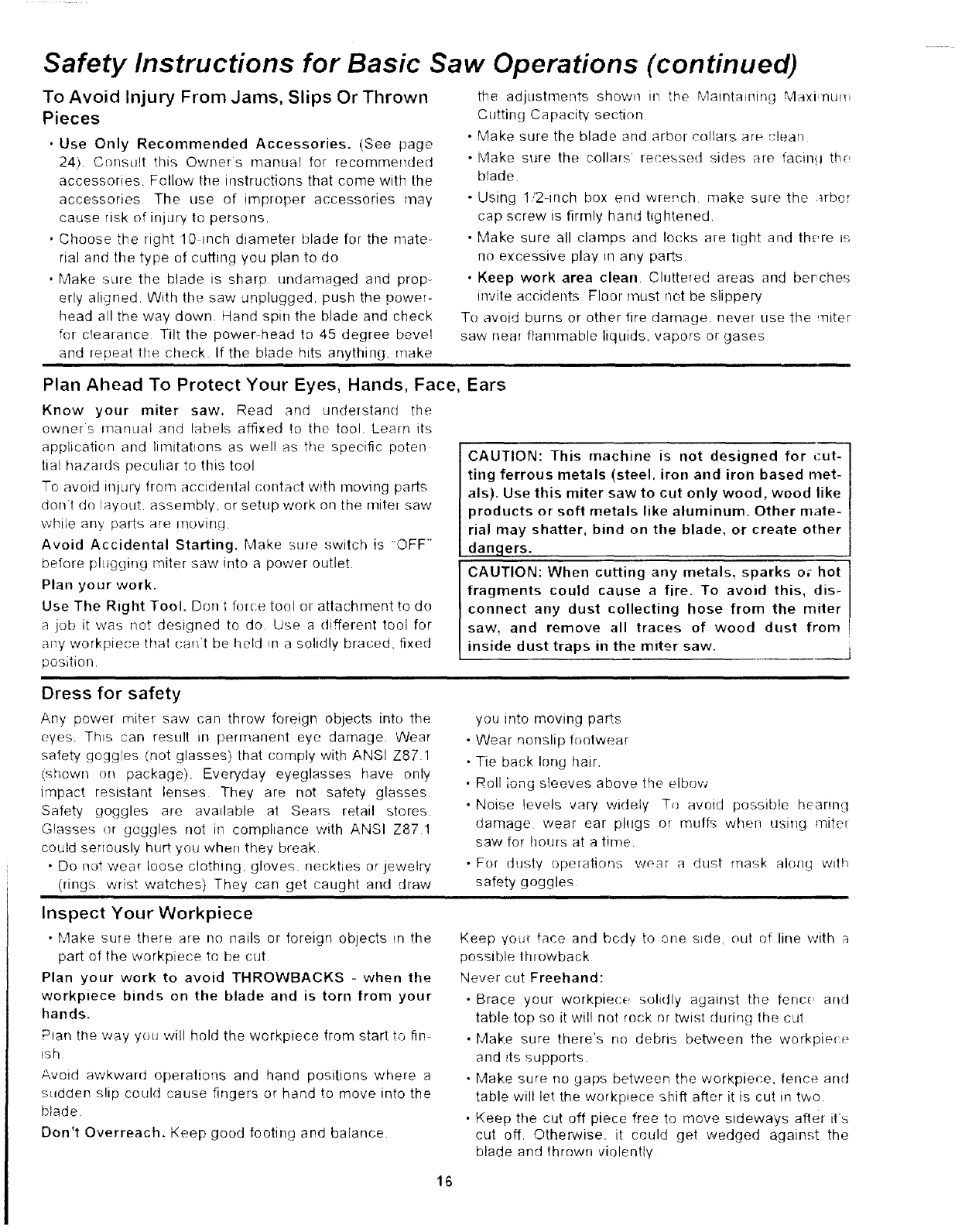
Catalog No. 9-22244 Leg Set
O O O O
©
cD o
o CD
cD CD 0'
lid
o c)
o cD
O
O 0 O O
I- 14 -I
Front Side Attach mounting board to holes indicated
Safety Instructions for Basic Saw Operations
Before Using The Saw
WARNING: To avoid mistakes that could cause
serious, permanent injury, do not plug the miter
saw in until the following steps are completed.
• Alignment. (See "Alignment/Adjustrnenr' section.)
• The saw is properly mounted (See pages 13 15).
• Learn the use and function of the ON-OFF switch,
upper and lower blade guards, handle latch, bevel
clamp, cover plate stop screw and fence clamps. (See
page 8).
• Review and understand all safety instructions and
operating procedures in this manual,
• Review the maintenance methods for this miter saw
(See page 24).
When Installing or Moving the Miter Saw
To avoid injury or death from electrical shock: • Make sure your lingers do not touch the plugs metal
prongs when plugging or unplugging the miter saw
Before Each Use
Inspect your saw,
Disconnect The Miter Saw. To avoid injury from acci
dental starting_ unplug the saw, before changing the
setup changing the blade or adjusting anything
Compare the direction of rotation airow oil the guard to
the direction arrow on blade The blade teeth should
always point downward at the front of the saw
Tighten the arbor screw
Tighten the cover plate stop screw.
Check Damaged Parts. Check fol
Alignment of moving parts.
Damaged electric cords,
Binding of rnoving parts,
Broken parts,
Stable mounting
Function of alrn return spring and lower guard: Push
the arm all the way down, then let it rise up until it
stops by itself. Check the lower guard to see if it closed
fully Ifitdid not. follow the instructions in the Trouble
Shooting section
• Other conditions that may affect the way the miter saw
works
Keep Guards In Place, in working order, and m proper
adjustment
If any part of this miter saw if missing, bent. of broken in
any way. or any electrical parts dont work, turn the saw
off and unplug it. Replace damaged, missing, or failed
parts before using the saw again.
Maintain Tools With Care. Keep the miter saw clean for
best and safest performance, Follow instructions for lubri
cating. DON'T put lubricants on the blade while it's spin-
ning.
Remove Adjusting Keys And Wrenches from tool
before turning it on
15
Safety Instructions for Basic Saw Operations (continued)
To Avoid Injury From Jams, Slips Or Thrown
Pieces
•Use Only Recommended Accessories. (See page
24). Consult this Owners manual for recommemJed
accessories. Follow the instructions that come with the
accessories The use of improper accessories may
cause risk of injury to persons.
• Choose the right 10 inch diameter blade for the mate-
rial and the type of cutting you plan to do
• Make sure the blade is sharp undamaged and prop-
erly aligned With the saw unplugged, push thepoweT-
head all the way down Hand spin the blade and check
for clealance Tilt the power-head to 45 degree bevel
and repeat the check If the blade hits anything, make
the adjustments shown in the Maintaining Max! nun
Cutting Capacity section
• Make sure the blade and arbor collars are ,*'lean
• Make sure the collars' recessed sides are facing th_
blade
oUsing 1/2-inch box end wrench make sure the arbe_
cap screw is firmly hand tightened
• Make sure all clamps and lecks are tight and there i_,_
no excessive play _nany parts
• Keep work area clean Cluttered areas and berches
invite accidents Floor must not be slippery
To avoid burns or other tire damage, never use the miter
saw nea_ ftamnlable liquids, vapors or gases
Plan Ahead To Protect Your Eyes, Hands, Face,
Know your miter saw. Read aqd understand the
owners manua! and labels affixed to the tool Learn its
application and limitations as well as the specific poten
tia! hazards peculiar to this tool
To avoid injury from accidental contact with moving parts
dont do layout assembly, or setup work on the mitel saw
while any parts are moving.
Avoid Accidental Starting. Make sale switch is "OFF"
before plugging miter saw irrto a power outlet
Plan your work.
Use The Right Tool. Dent fol(-e tool or attachment to do
a job it was not designed to do Use a different tool for
any workpiece that ca_Yt be held in a solidly braced, fixed
position.
Ears
CAUTION: This machine is not designed for cut-
ting ferrous metals (steel, iron and iron based met-
als). Use this miter saw to cut only wood, wood like
products or soft metals like aluminum. Other mate-
rial may shatter, bind on the blade, or create other
danglers.
CAUTION: When cutting any metals, sparks o_ hot
fragments could cause a fire. To avoid this, dis-
connect any dust collecting hose from the miter
saw, and remove all traces of wood dust from !
inside dust traps in the miter saw. i
Dress for safety
Any powel mitet saw can throw foreign obJects into the
eyes. This can result _rl permanent eye damage. Wear
safety goggles (not glasses) that comply with ANSI Z87.1
(shown on package). Everyday eyeglasses have only
impact resistant lenses They are not safety glasses
Safety goggles are available at SeaTs retail stores
Glasses or goggles not in compliance with ANSI Z87 1
could seriously hurt you when they break
• Do not wear loose clothing, gloves, neckties or jewelp/
(rings wrist watches) They can get caught and draw
you into moving parts
- Wear nonslip footwear
• Tie back long hair.
• Roll long sleeves above the elbow
• Noise levels vary widely To avoid possible hearing
damage wear ear plugs or muffs when using mite[
saw for hoHrs at a time
• For dHsty operatio_3s wear a dust mask along with
safety goggles
Inspect Your Workpiece
• Make sure there are no nails or foreign objects in the
part of the workpie('e te be cut
Plan your work to avoid THROWBACKS - when the
workpiece binds on the blade and is torn from your
hands.
Plan the way you wil! hold the workpiece from start to fin
ish
Avoid awkward operations and hand positions where a
sudden slip could cause fingers or hand to move into the
blade
Don't Overreach. Keep good footing and balance
Keep your face and body to one side, out of line with a
possible throwback
Never cut Freehand:
• Brace your workpiece solidly against the fence and
table top so it wil! not rock or twist dudog the cut
• Make sure there's no debris between the workpiece
and its supports
• Make sure no gaps between the workpiece, fence and
table will let the workpiece shift after it is cut in two.
• Keep the cut off piece free to move sideways after it's
cut off. Otherwise. it could get wedged against the
blade and thrown violently
16
• Clea+ ew.wtfung except the wgrkpm(e and flared
support deviso<_ .ff the table before tHrnind th_ rnitet
saw )PI
• Secure Work. tJse damps or a ,/so to M4f _, lurid !he
work when its pradica!
Use extra caution with large, very small or awkward
workpieces:
• U,-;e _xt_a suppods (tables saw hor_es block':. ,to ._
fo_ a_/y workpieces large, enougt! to tip when r I b,4d
down to the table top
• Never _se another pe.mon as a substitute tel a table
extension, or as addihollal support f.or a werkpl_<:e that
is hanger oI wider than the basra ;Tilter saw'lab_ r;r !o
helb feed supper!or pull thewerkp!ece
• Do Ht)t Hs_ thi t_ qaw to cut pie_:es ioc, small to i_,t _m+
easily hold the workwhde you keep the thumb sid_ _:,f
your index (pomle+) finger agaustthe outside <tg+ of
th_ frm_:e
•Wh,,_n cHttHl{] irregHlady shaped wolkplee;es, pl 4!+ VgUr
wr)lk {i] i! will not slip arid t:ma:h the blade and be 1<)in
from you; haHds A piece of molding, fP,r ex_mi)le
muqt :;_ fi!! +;r !)? held !v af x+< ,_ ; +-]a!
+ttw_s! 'ock ('r 9up +,_hd+, h_',,_,_ ,1
o Probu_lysul:pud_uHadruabuh, -.' "-. ',,,w_ +' :,i
tUblrlg _hev have a [pr_rl#[ r,II %!11 [)e i'(,
causirq the _:L_'J_; ts t'l+_ ' _,( +vo,d +P,< al',_.a ,B .
fiytur,: desigued h) wopedv ,_m,1 votH _,.,_.,i+_; c_ -,
WARNING: If plann!ng to cu! aluminum or oth,_r
non-ferrous metals Under adverse conditions, th_
blade can grab and throw the workpiece suddenl,
and unexpectedly To avoid injury, follow all apph-
cable safety instructions, as you normally ,vou_{_
and:
Use only sawblades st ecif_cally recommend_,d
for qomferrous metalcuttinu
Do not cut ;lletal workp_eees that must he hand
held Us_ auxiliary clamps or other equ_pmen! +is
needed,
• Cut non-ferrous metals on _, _t you are _xper,-
enced or under the s!lpervis_on of an experienced
person.
Whenever Saw Is Running
quent use of your miter saw) cause a careless mis+
take A careless fraction of a second is enough to
cause a severe injury,
_(?foIo %fa!ltnq yoIll (:ti_ watch the mite[ saw whde it
luns tfit makes an unfamiliar noiseor vibrates a!ot. step
utqmed_alely Turn the saw off Unplug the saw Do net
restmt until finding and collecting the problem
Keep Children Away Keep all visitors a safe dislallc(
flora the mdeI saw Make sure bystanders are :iear of
the mihq saw and workpiece
Neve_ uonline the piece being ,':ul off Never hold it
clamp it lotE:h it. oI use length stops against it while the
blade ,s spinning tt must be free to move sideways on ils
own !1 confhled, ii could get wedged against the b_de
and thi{_wn violently
Let the blade leach full speed behve cutting
Don't Force Tool. 11 wili (i) th_ c,_; i_elte a!=d . __'! a 't
des_gap?, late reedlhe_-av/ !h th_ ,:+_ q,f.,r{_, , hi+ + s.'
(I]OIICt !{ l_!t t'_F ba(h ( 11with(it _.,_!,_!I1 <_{.',\vrt )I i,q '.
HW_
Before freeinq jammed materiah
, Ttilrt _wit('h ()F _-
•Unph_g the r'qitel s _'.'
• Wa!t for all moving pad> t_: st ,,.>
After finishing a cut:
•Keep holding the pewe_ hea! do;,-n
• Release the swituh _nd ,/aq for al nx)*.;ill] )art, t<
stop !)efore r_-,ovlnq V(,LiF har_d_-
• If blade doesnt stop witCH 6 >ecor]dc: !J!][_l ]{..j rh(-? >L%
a!!d follow the !nstrtlctions !n the Troill ! _ Sh )_)1,1_!:!_ ,<
tiw fl); t]Xil/,'.] the tlade hl]ke t:e+_h, tZe, ll!g "h( %.3.
a{laH!
Before Leaving The Saw
Never Leave Tool Running Unattended. Turn bnwe+
off Wait fOl all nlovmc! parts to sh_p
t2,aka wciKSi_o F child pre_of Lock tile sh+'_ O'.:.cor ! ._, !
master ,_witches Stc,_,= tool away l+orq {:! idren ml t!
eTs nnt ]ualified to Hse rise t<,,ol
17
Basic Saw Operations
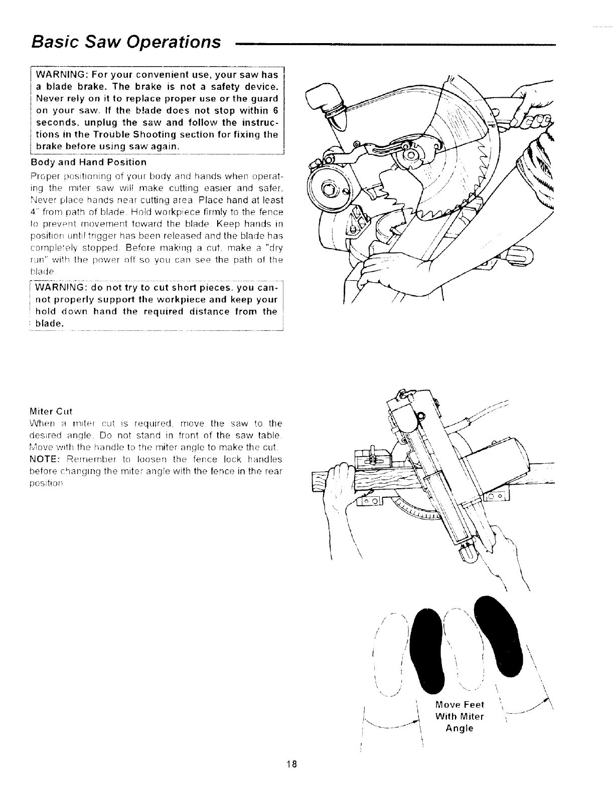
WARNING: For your convenient use, your saw has I
a blade brake. The brake is not a safety device.
Never rely on it to replace proper use or the guard
on your saw, If the blade does not stop within 6
seconds, unplug the saw and follow the instruc-
tions in the Trouble Shooting section for fixing the
brake before using saw again.
Body and Hand Position
Proper positioning of your budy and hands when operat-
ing the rotter saw will make cutting easter and safer.
Never place hands near cutting area Place hand at least
4" fronl path otblade Holdworkpiece fitmlytottle fen,ce
to prewmt m_vement toward the blade Keep hands m
positioi_ until trigger has been released and the blade has
co_lple el_ stopped Before makin(l a cut make a "dry
rJn" with the power off so you can see the path of the
blade
WARNING: do not try to cut short pieces, you can-
not properly support the workpiece and keep your
held down hand the required distance from the
blade.
Miter Cut
v_hen a mdet cut Is required, move the saw to the
desired angle. Do not stand in f[ont of the saw table
Move w_th the handle to the miter angle to make the cut
NOTE: Remembe! to leosen the fence lock handles
before changing the miter angPe with the fence in the rear
position
\\\
18
Move Feet
With Miter
Angle
\
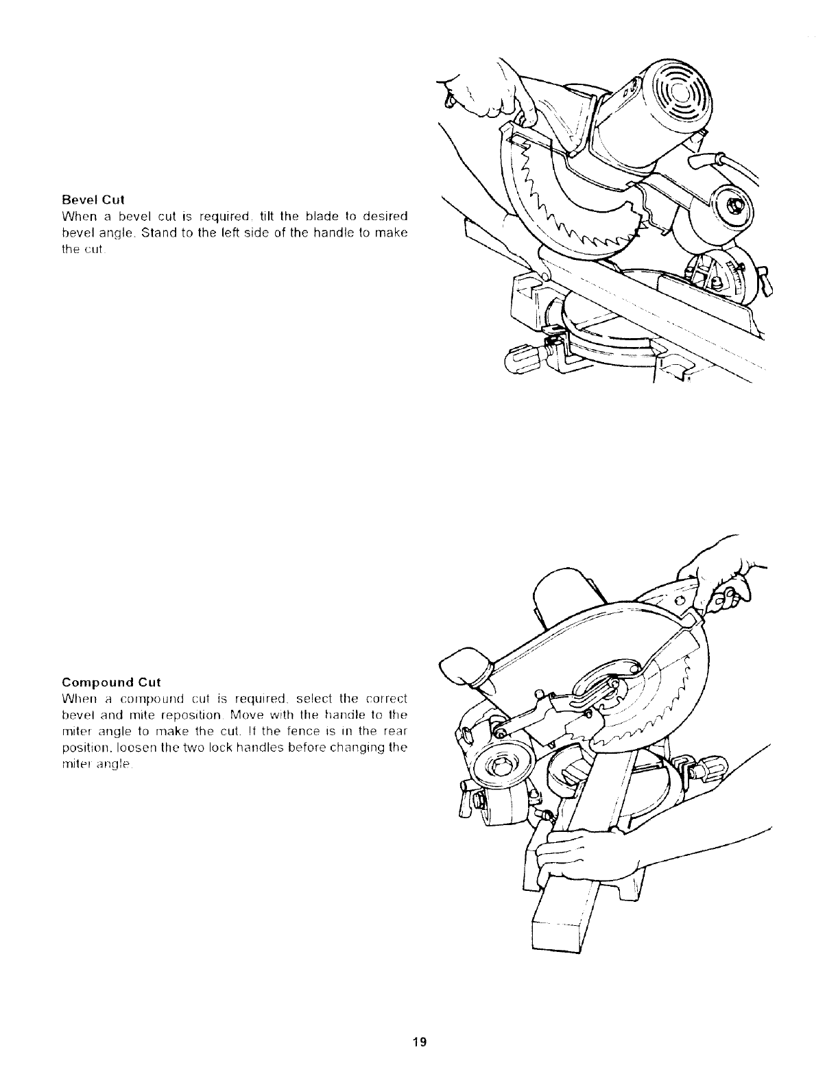
Bevel Cut
When a bevel cut is required, tilt the blade to desired
bevel angle. Stand to the left side of the handle to make
the cut
Compound Cut
When acompound cut is required, select the correct
bevel and mite reposition Move with the handle to lhe
mite_ angle to make the cut. If the fence is in the rear
position, loosen the two lock handles before changing the
miler angle I
19
Basic Saw Operations (continued)
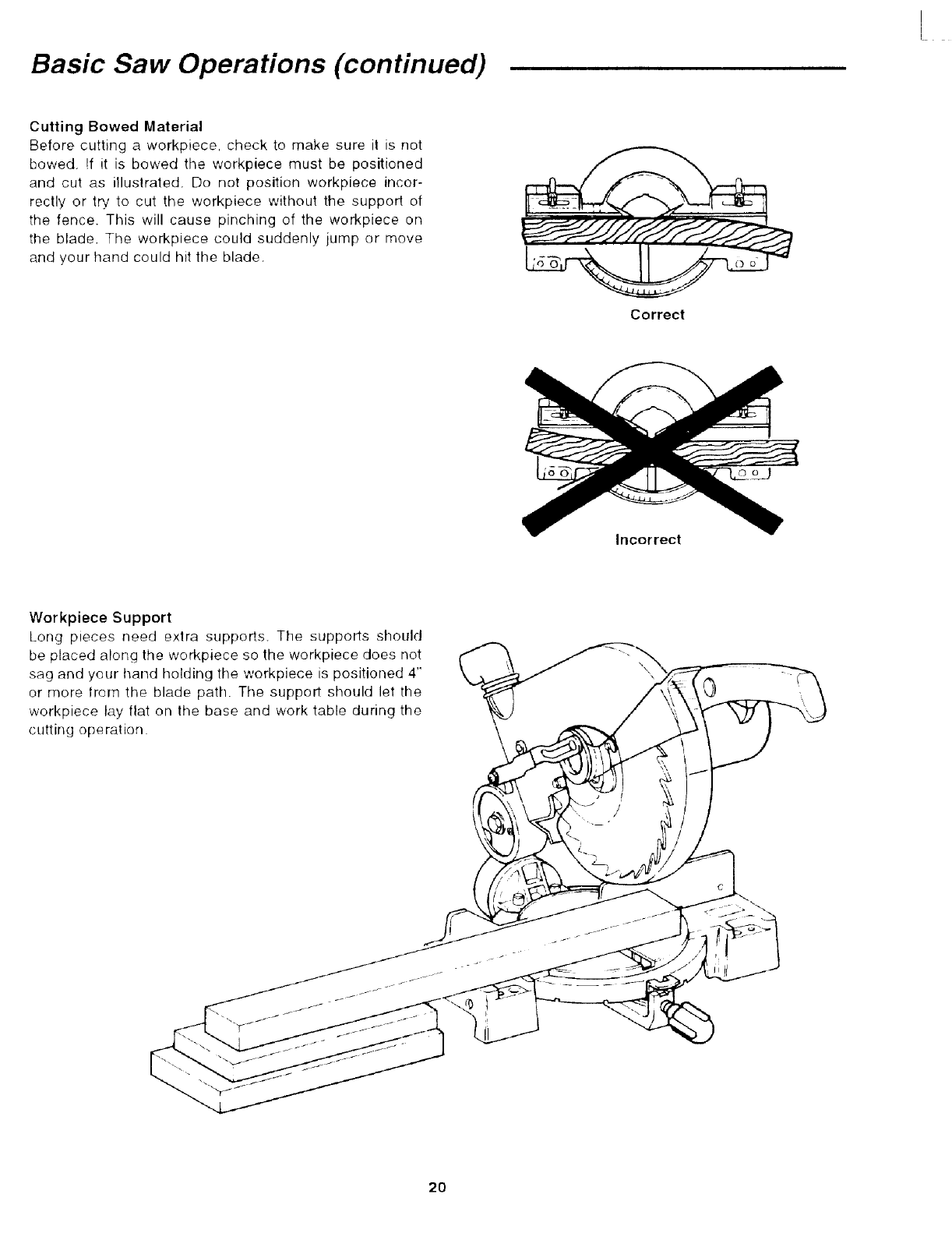
Cutting Bowed Material
Before cutting a workpiece, check to make sure it is not
bowed. !f it is bowed the workpiece must be positioned
and cut as illustrated. Do not position workpiece incor-
rectly or t_' to cut the workpiece without the support of
the fence. This will cause pinching of the workpiece on
the blade. The workpiece could suddenly jump or move
and your hand could hit the blade.
Correct
Incorrect
Workpiece Support
Long pteces need extra supports. The supports should
be placed along the workpiece so the workpiece does not
sag and your hand holding tile workpiece is positioned 4"
or more from the blade path. The support should let the
workpiece lay flat on the base and work table during the
cutting operation
c
20
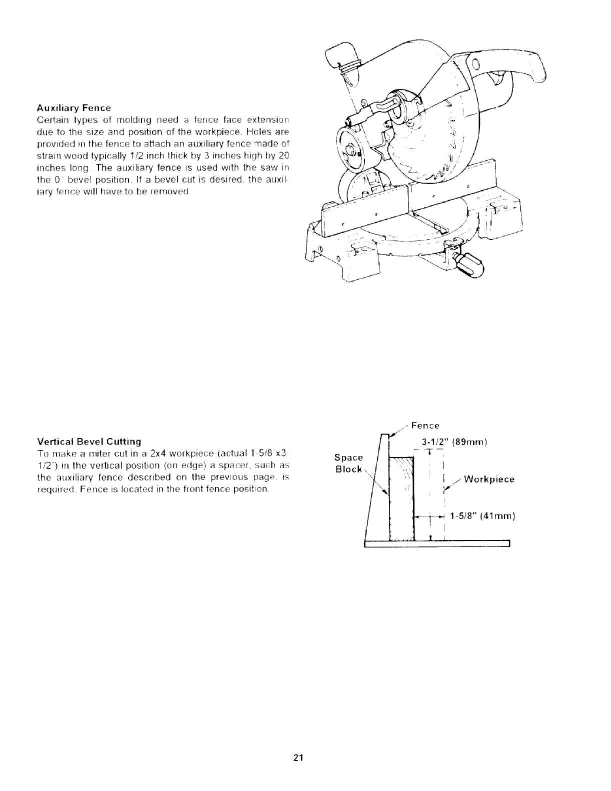
AuxiliaryFence
Ce(tainlypesof moldingneeda fencefaceextension
duetothesizeandpositionoftheworkpiece.Holesare
providedinthefenceto attachanauxiliaryfencemadeof
strainwoodtypically1/2inchthickby3incheshighby20
incheslong Theauxiliaryfencetsusedwiththesawin
the0_bevelposition.If abevelcutisdesired,theauxi(
iaryfencewillhaveto beremoved
VerticalBevelCutting
Tomakea mitelcutina 2x4workpiece(actual15/8x3
1/2) intheverticalposition(onedge)aspacer,su(has
the auxiliaryfencedescribedonthe previouspage is
requiredFenceislocatedinthefrontfenceposition
Space
Block_
21
Basic Saw Operations (continued)
Helpful Hints When Cutting Compound
Miters
Tips for Cutting Compound Miters on Picture
Frames and Boxes
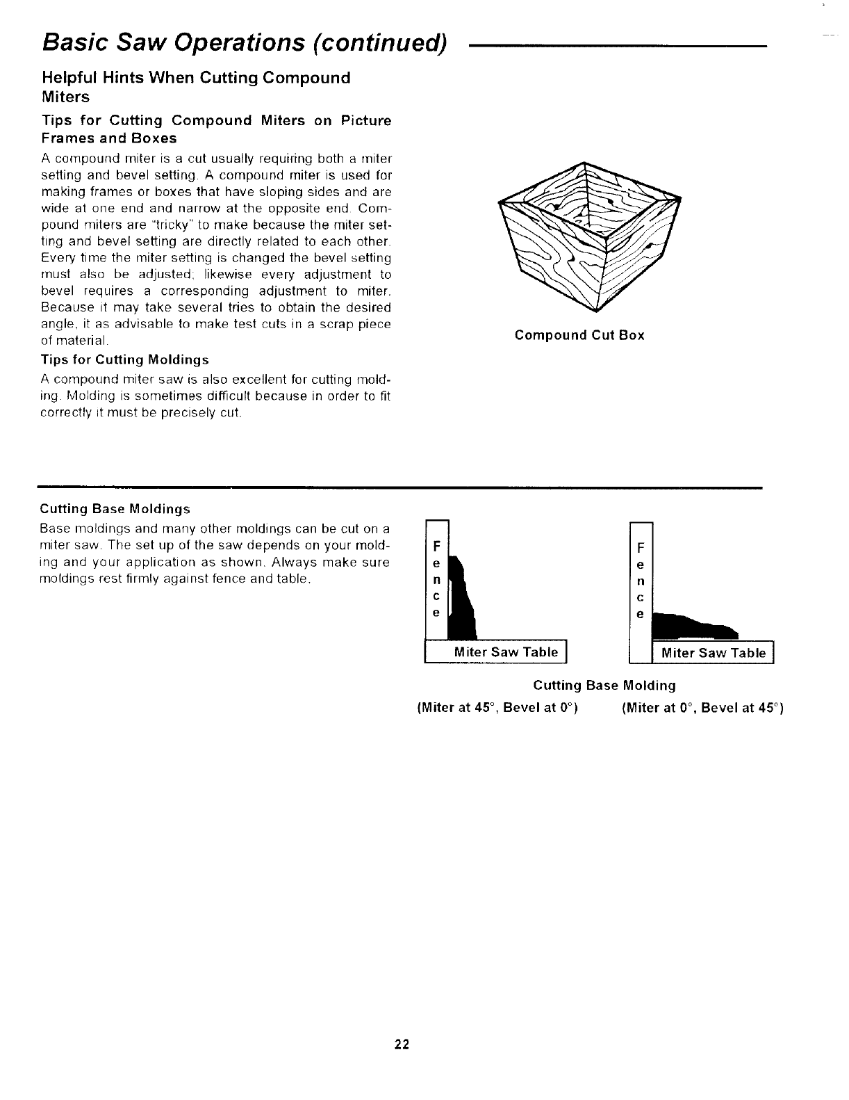
A compound miter is a cut usually requiring both a miter
setting and bevel setting. A compound miter is used for
making frames or boxes that have sloping sides and are
wide at one end and narrow at the opposite end Com-
pound miters are "tricky" to make because the miter set-
ting and bevel setting are directly related to each other.
Every time the miter setting is changed the bevel setting
must also be adjusted: likewise every adjustment to
bevel requires a corresponding adjustment to miter.
Because it may take several tries to obtain the desired
angle, it as advisable to make test cuts in a scrap piece
of material
Tips for Cutting Moldings
A compound miter saw is also excellent for cutting mold-
ing Molding is sometimes difficult because in order to fit
correctly it must be precisely cut.
Compound Cut Box
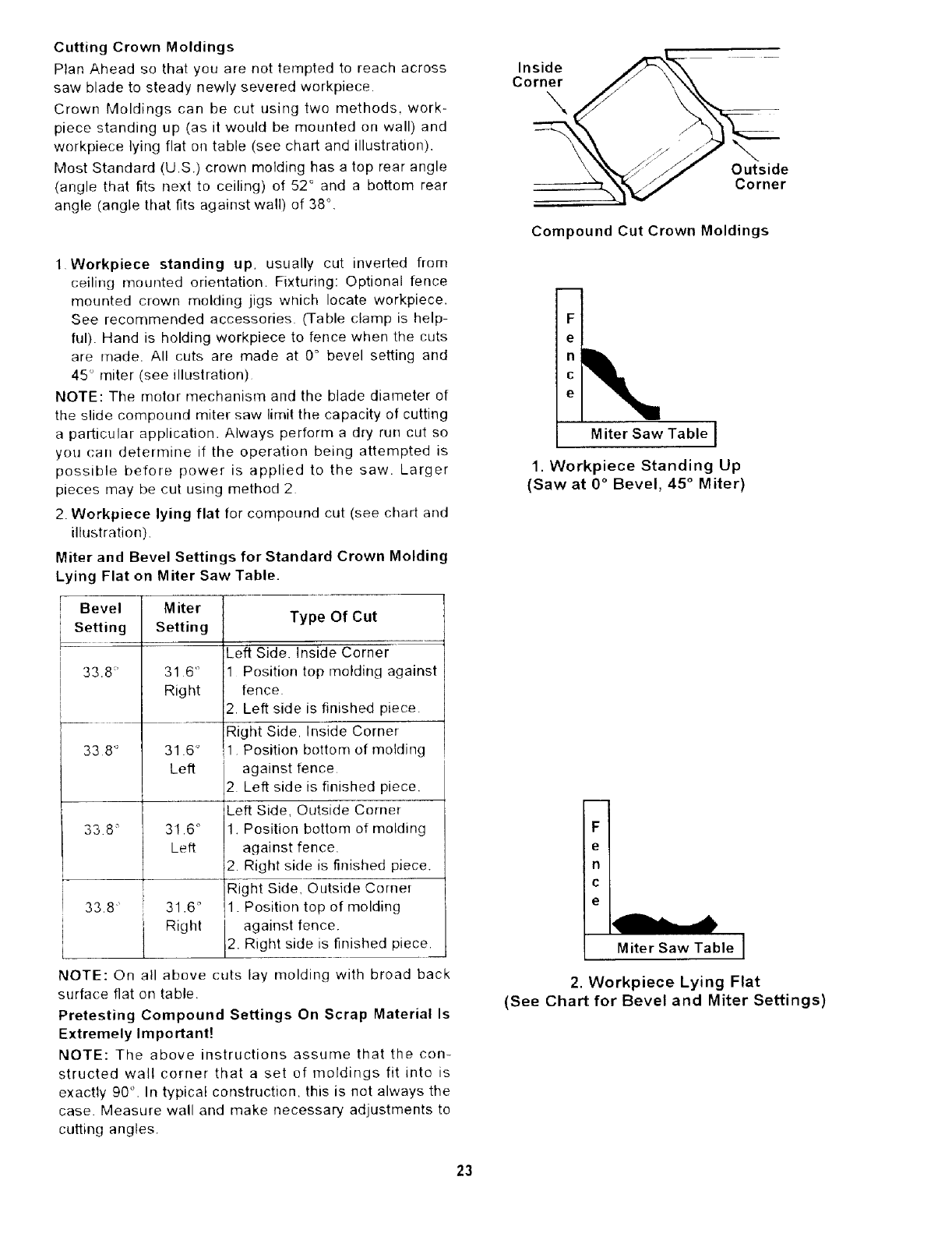
Cutting Base Moldings
Base moldings and many other moldings can be cut on a
miter saw. The set tip of the saw depends on your mold-
ing and your application as shown, Always make sure
moldings rest firmly against fence and table.
F
e
n
C
e
Miter Saw Table Miter Saw Table I
Cutting Base Molding
(Miter at 45 °, Bevel at 0°) (Miter at 0°, Bevel at 45 °)
22
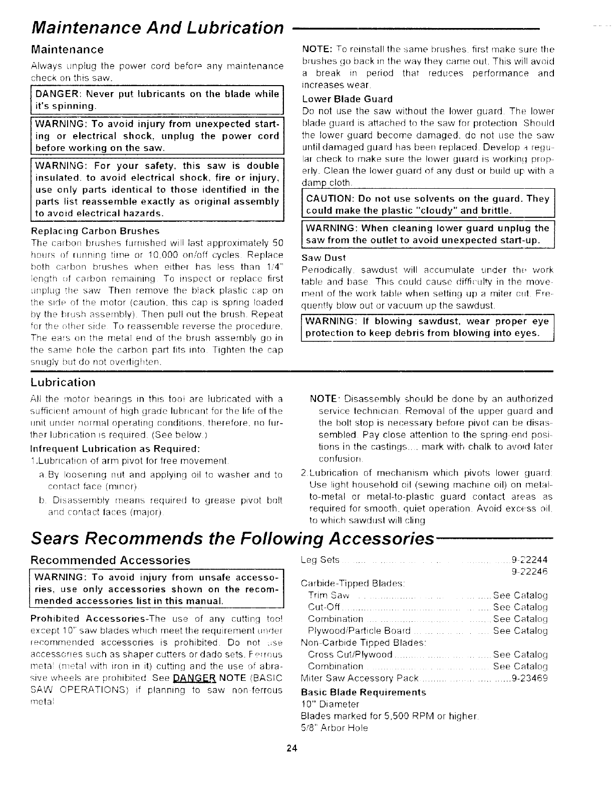
Cutting Crown Moldings
Plan Ahead so that you are not tempted to reach across
saw blade to steady newly severed workpiece.
Crown Moldings can be cut using two methods, work-
piece standing up (as it would be mounted on wall) and
workpiece lying flat on table (see chart and illustration).
Most Standard (U.S.) crown molding has a top rear angle
(angle that fits next to ceiling) of 52 ° and a bottom rear
angle (angle that fits against wall) of 38 °.
1 Workpiece standing up. usually cut inverted from
ceiling mounted orientation. Fixturing: Optional fence
mounted crown molding jigs which locate workpiece.
See recommended accessories (Table clamp is help-
ful). Hand is holding workpiece to fence when the cuts
are made. All cuts are made at 0° bevel setting and
45 ° miter (see illustration)
NOTE: The motor mechanism and the blade diameter of
the slide compound miter saw limit the capacity of cutting
aparticular application. Always perform a dry run cut so
you can determh]e if the operation being attempted is
possible before power is applied to the saw. Larger
pieces may be cut using method 2
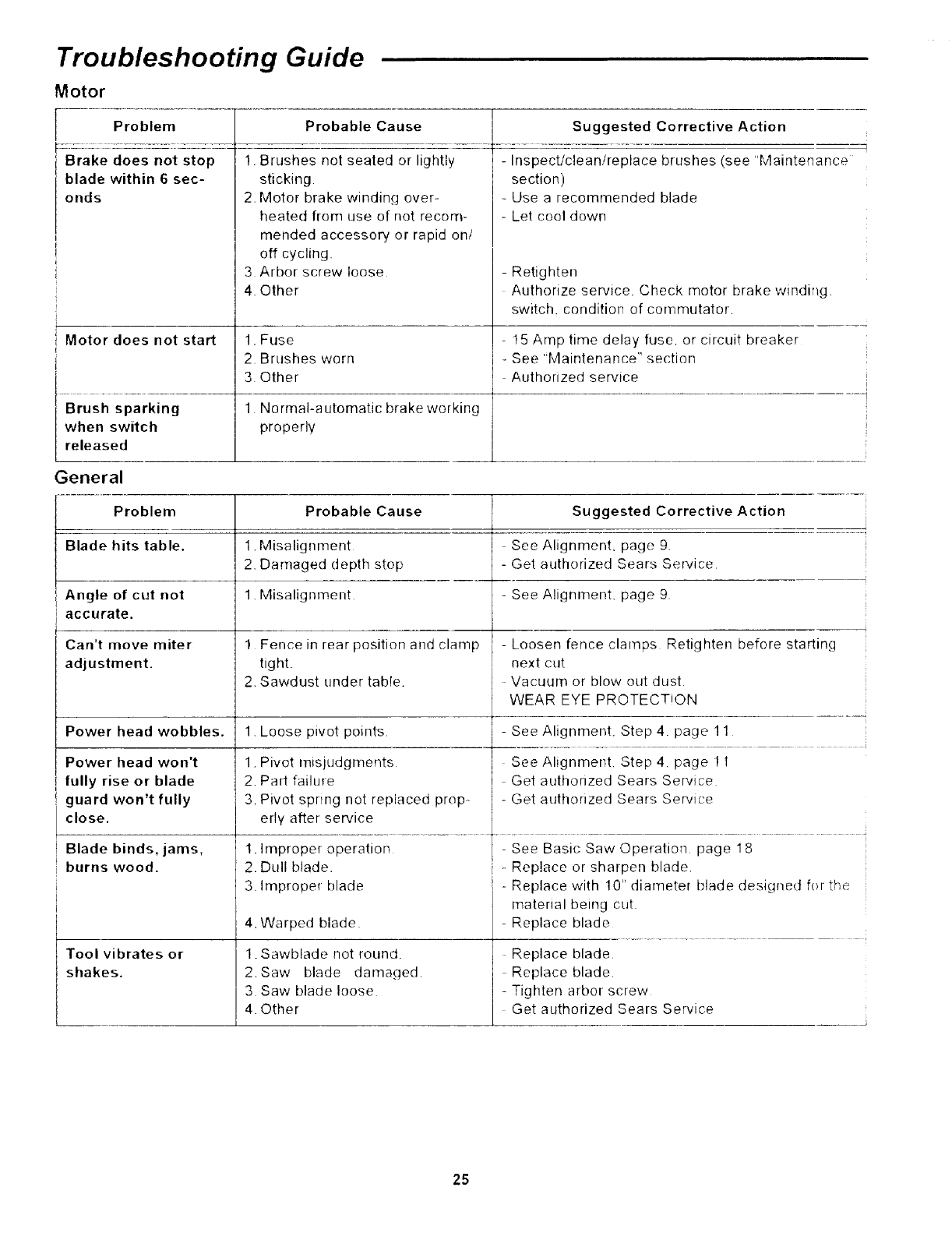
2. Workpiece lying flat for compound cut (see chart and
illustration)
Miter and Bevel Settings for Standard Crown Molding
Lying Flat on Miter Saw Table.
Bevel
Setting
33.8'
M iter
Setting
31 6 '_
Right
33 8 ° 31.6 °
Left
338 ° 31.6 °
Left
33.8" 31.6 °
Right
Type Of Cut
Left Side. Inside Corner
1 Position top molding against
fence
2. Left side is finished piece.
Right Side, Inside Corner
1 Position bottom of molding
against fence
2 Left side is finished piece.
Left Side, Outside Corner
1. Position bottom of molding
against fence.
2. Right side is finished piece.
Right Side, Outside Cornel
1. Position top of molding
against fence.
2. Right side is finished piece.
NOTE: On all above cuts lay molding with broad back
surface fiat on table
Pretesting Compound Settings On Scrap Material Is
Extremely Important!
NOTE: The above instructions assume that the con-
structed wall corner that a set of moldings fit into is
exactly 90 ° . In typical construction, this is not always the
case. Measure wall and make necessary adjustments to
cutting angles.
Inside
Corner
Outside
Corner
Compound Cut Crown Moldings
F
e
c
e
Miter Saw Table I
1. Workpiece Standing Up
(Saw at 0 ° Bevel, 45 ° Miter)
FI
el
n l
c I
el
2. Workpiece Lying Flat
(See Chart for Bevel and Miter Settings)
23
Maintenance And Lubrication
Maintenance
Always unplug the power cord befor ,= any maintenance
check on this saw.
DANGER: Never put lubricants on the blade while
it's spinning.
WARNING: To avoid injury from unexpected start-
ing or electrical shock, unplug the power cord
before working on the saw.
WARNING: For your safety, this saw is double
insulated, to avoid electrical shock, fire or injury,
use only parts identical to those identified in the
parts list reassemble exactly as original assembly
to avoid electrical hazards.
Replacing Carbon Brushes
The talbot1 brt_shes furnished will last approximately 50
hours of running time or I0,000 on/off cycles Replace
both carbon brushes when either has less than 1/4"
engti_ (_f carbon remaining To inspect or replace first
'mpMg the saw Then rernove the black plastic cap on
th,e side of the motor (caution, this cap is spring loaded
by the brush assembly) Then pull out the brush. Repeat
fol thetthe_ side To reassemble leversethe procedure
The ears on the metal erld of the brush assembly go in
the same hole the carbon part fits into Tighten the cap
snugly but do not overtighten.
NOTE: To reinstall the same brushes first make sure the
brushes go back m the way they came out. This will aw:fid
a break m period that reduces performance arrd
increases wear
Lower Blade Guard
Do not use the saw without the lower guard The lower
blade guard is atlached to the saw for protection Should
the lower guard become damaged, do not use the saw
until damaged guard has been replaced. Develop a regu-
lar check to make sure the lower guard is working prop-
erly. Clean the lower guard of any dust or build up with a
damp cloth I
CAUTION: Do not use solvents on the guard. They ]
could make the plastic "cloudy" and brittle. I
WARNING: When cleaning lower guard unplug the J
saw from the outlet to avoid unexpected start-up.
Saw Dust
Periodically sawdust will accumulate under thu work
table arrd base This could cause diffi(ulty in tile move
merit ofihework table when settiog up a miter cut Fre-
quent!y blow out or vacuum up the sawdust.
WARNING: If blowing sawdust, wear proper eye
protection to keep debris from blowing into eyes.
Lubrication
All the motor bearings m this tooi are lubricated with a
sufficient amount of high grade lubricant for the lif_- of the
unit under normal operating c(mditions, therefore oolur-
therlubricationts required (See below)
Infrequent Lubrication as Required:
1.Lubrication of arm pivot for free movement
a By loosening nut and applying oil to washer and to
contact face (miner)
b Disassembly means required to grease pivot bolt
and cot]tact laces (major}
NOTE: Disassembly should be done by an authorized
service technician Removal of the upper guard and
tile [)()it stop is necessary before piw)t can be disas
sembled Pay close attention to the spring end posi-
tions in the castings .... mark with chalk to avoid later
confusion
2 Lubrication of mechanism which pivots lower guald:
Use light household oil (sewing machine oil) on metal-
to metal or metal to plastic guard contact areas as
required for smooth, quiet operation Avoid excess oil,
to which sawdust will cling
Sears Recommends the Following Accessories
Recommended Accessories Leg Sets ......................................... 922244
WARNING: To avoid injury from unsafe accesso-
ries, use only accessories shown on the recom-
mended accessories list in this manual.
Prohibited Accessories-The use of any cutting too!
except 10" saw blades which meet the requirement tlp,del
recommended accessories is prohibited Do not :;se
accessoqes such as shaper cutters or dado sets. Ferrnus
metal (n_etal with iron in it) cutting and the use of abra-
sive wheels ale prohibited See DANGER_ NOTE (BASIC
SAW OPERATIONS) if planning to saw non ferrous
metal
9 22246
Carbide-Tipped Blades:
Trim Saw .................................... See Catalog
Cut-Off ................................................. See Catalog
Combination ............. See Catalog
Plywood/Particle Board See Catalog
Non Carbide Tipped Blades:
Cross Cut/Plywood ............................. See Catalog
Combination ...................................... See Catalog
Miter Saw Accessory Pack ................... 9-23469
Basic Blade Requirements
10" Diameter
Blades marked for 5,500 RPM or higher
5/8" Arbor Hole
24
Troubleshooting Guide
Motor
Problem Probable Cause Suggested Corrective Action
Brake does not stop 1. Brushes not seated or lightly
blade within 6sec- sticking
ands
3
4,
- Inspect/clean!replace brushes (see "Maintenance
section)
- Use a recommended blade
- Let cool down
- Retighten
Authorize service. Check motor brake winding,
switch, condition of commutator
Motor brake winding over-
heated from use of not recom-
mended accessory or rapid on/
off cycling,
Arbor screw loose
Other
Fuse
Brushes worn
Other
No rmal-a utomatic brake war king
properly
Motor does not start 1. - 15 Amp time delay fuse. or circuit breaker
2 - See "Maintenance" section
3 Authorized service
Brush sparking 1
when switch
released
General
Problem
Blade hits table.
Angle of cut not
accurate.
Probable Cause
1. Misalignment
2. Damaged depth stop
1. Misalic nment
Can't move miter
adjustment.
Power head wobbles.
Power head won't
fully rise or blade
guard won't fully
close.
Blade binds, jams,
burns wood.
Tool vibrates or
shakes.
Suggested Corrective Action
See Alignment, page 9.
- Get authorized Sears Service
- See Alignment, page 9.
1 Fence in rear position and clamp -Loosen fence clamps Retighten before starting
tight, next cut
Vacuum or blow out dust
2. Sawdust tinder table. WEAR EYE PROTECTION
1. Loose pivot points j-See Alignment. Step 4. page 11
1. Pivot misjudgments I See Alignment, Step 4, paget1
2. PallfailuTe I Get authorized Sears Service
3. Pivot spring not replaced prop- - Get authorized Sears Service
1. Improper operation / -See Basic Saw Operation page 18
2. Dull blade, i - Replace or sharpen blade.
3 Improper blade , -Replace with 10" diameter blade designed f(_l the
material being cut
4, Warped blade - Replace blade
1.Sawblade not round. Replace blade
2.Saw blade damaged Replace blade.
3 Saw blade loose - Tighten arbor screw
4. Other Get authorized Sears Service
25
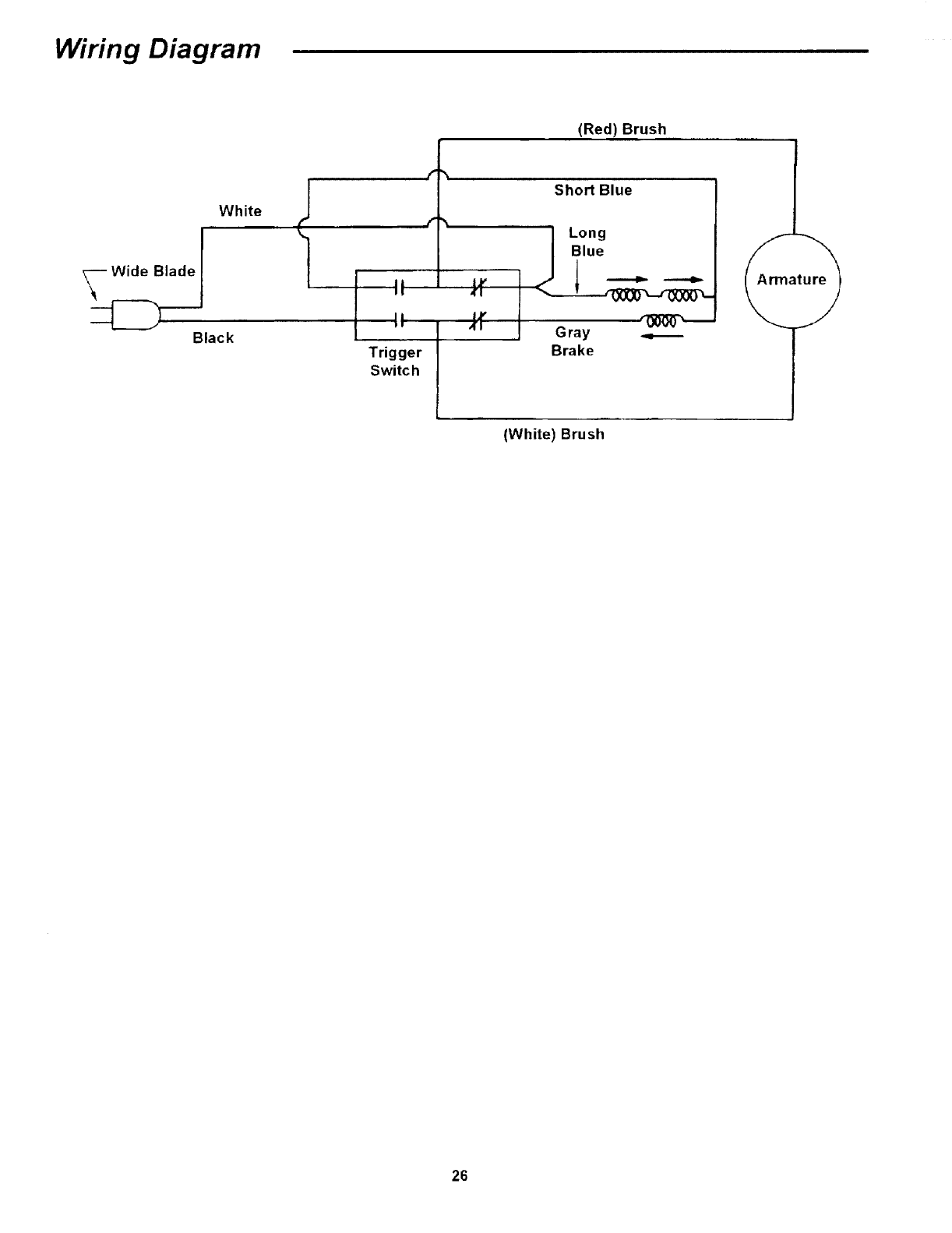
Wiring Diagram
White
Black Trigger
Switch
Gray
Brake
(White) Brush
(Red) Brush
26

Notes
27
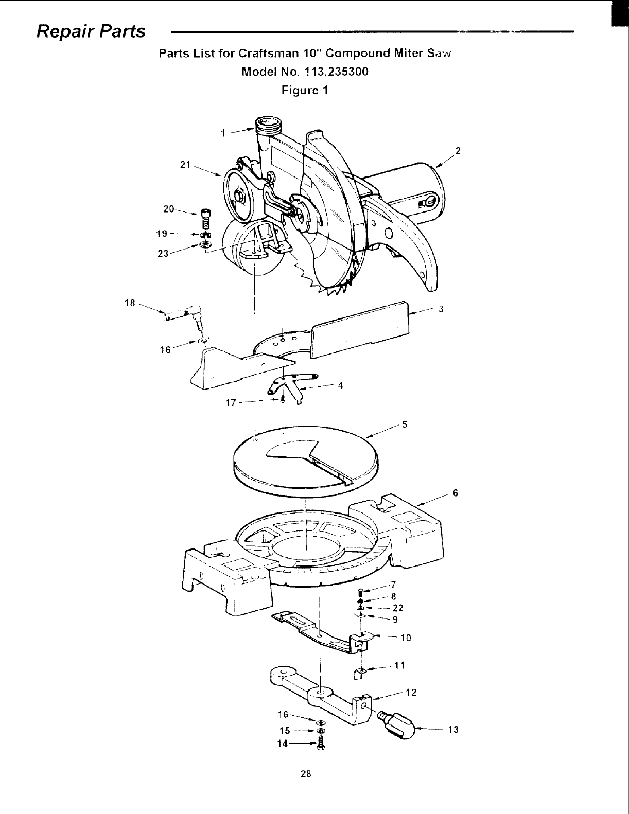
Repair Parts
Parts List for Craftsman 10" Compound Miter Sa',-J
Model No. 113.235300
Figure 1
21
(
15 ---_
14-----"
_ .,_---- 11
12
13
28
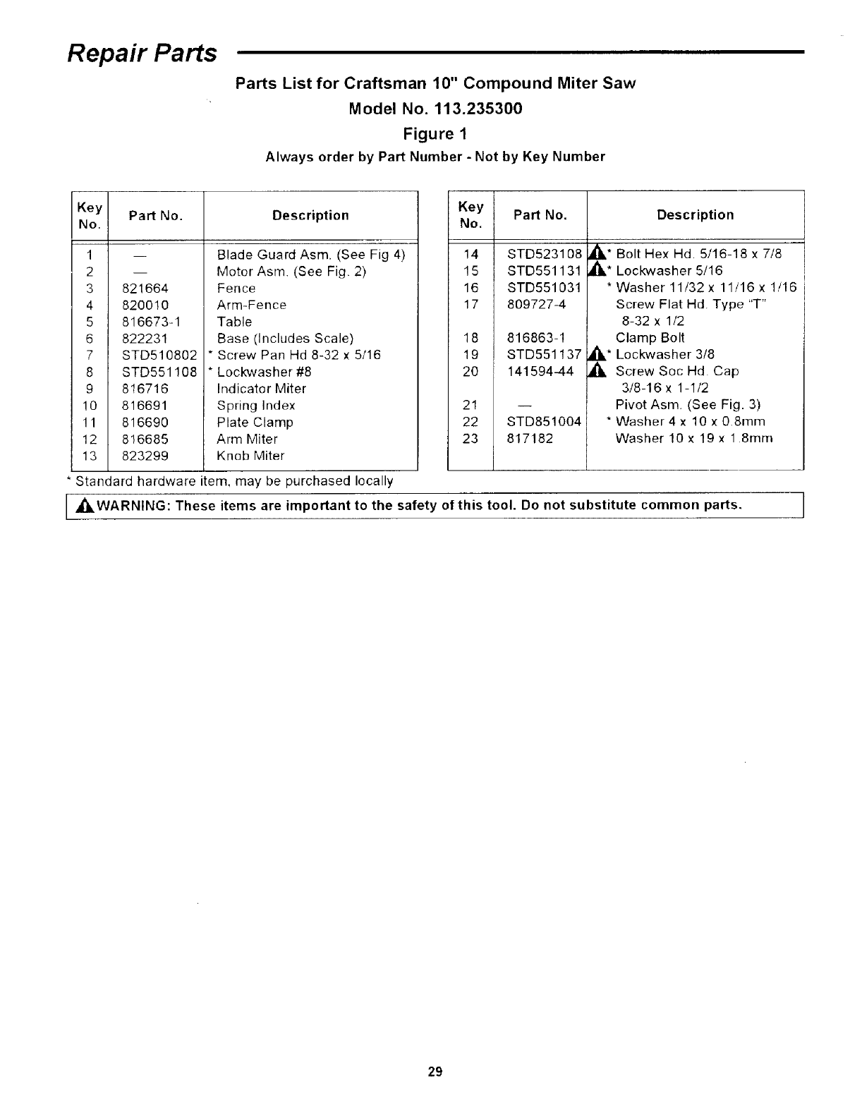
Repair Parts
Parts List for Craftsman 10" Compound Miter Saw
Model No. 113.235300
Figure 1
Always order by Part Number- Not by Key Number
Key Part No. Description
No.
1
2
3
4
5
6
7
8
9
10
11
12
13
m
821664
820010
816673-1
822231
STD510802
STD551108
816716
816691
816690
816685
823299
Blade Guard Asm (See Fig 4)
Motor Asm (See Fig. 2)
Fence
Arm-Fence
Table
Base (Includes Scale)
* Screw Pan Hd 8-32 x 5/16
* Lockwasher #8
Indicator Miter
Spring Index
Plate Clamp
Arm Miter
Knob Miter
Key
No.
14
15
16
17
18
19
20
21
22
23
Part No.
STD523108
STD551131
STD551031
809727-4
816863-1
STD551137
14159444
STD851004
817182
Description
_1_* Bolt Hex Hd. 5/16-18 x 7/8
_1_* Lockwasher 5/16
* Washer 11/32 x 11/16 x 1/16
Screw Flat Hd. Type "T"
8-32 x 1/2
Clamp Bolt
_* Lockwasher 3/8
_, Screw Soc Hd Cap
3/8-16 x 1 1/2
Pivot Asm (See Fig. 3)
* Washer 4 x 10 x 0.8mm
Washer 10 x 19 x 1 8ram
Standard hardware item, may be purchased locally
[ _,WARNING: These items are important to the safety of this tool. Do not substitute common parts. /
L/
29
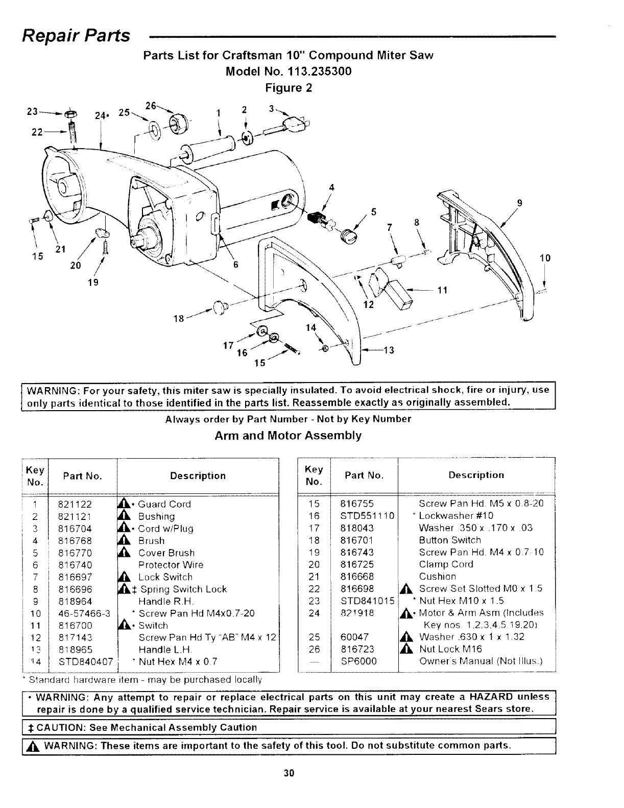
Repair Parts
\
! 21
15 20 /
19
Parts List for Craftsman 10" Compound Miter Saw
Model No. 113.235300
Figure 2
2 3-_
\12
14\
I ARNING: For your safety, this miter saw is specially insulated. To avoid electrical shock, fire or injury, use
only parts identical to those identified in the parts list. Reassemble exactly as originally assembled.
Always order by Part Number - Not by Key Number
Arm and Motor Assembly
Key Part No.
No.
1 821122
2 821121
3 8167O4
4 816768
5 816770
6 816740
7 816697
8 816696
9 818964
10 46-57466-3
11 816700
!2 817143
1_ 818965
14 STD840407
Description
_,. Guard Cord
_IL Bushing
,d_,.Cord w/Plug
_, Brush
Cover Brush
. Protector Wire
Lock Switch
_,:l: Spring Switch Lock
Handle R.H.
* Screw Pan Hd M4x0.7-20
I_..Switch
Screw Pan Hd Ty "AB" M4 x 12
Handle L.H
* Nut Hex M4 × 07
__r
15
16
17
18
19
20
21
Key Part No.
No.
816755
STD551110
818043
816701
816743
816725
816668
22 816698
23 STD841015
24 821918
25 60047
26 816723
] SP6000
Standard hardware item - may be purchased locally
• WARNING: Any attempt to repair or replace electrical parts
Description
Screw PanHd MSx08-20
Lockwasher #10
Washer 350x .170x 03
Button Switch
Screw Pan Hd M4x 07 10
Clamp Cord
Cushion
_. Screw Set Slotted M0 x 1 5
* Nut Hex M10 x 1.5
_. Motor & Arm Asm (Includes
Keynos 1.2.3,45 19,20)
_, Washer .630 x 1 x 1.32
_1, Nut Lock M16
Owner*s Manual (Not Illus )
on this unit may create a HAZARD unless
repair is done by aqualified service technician. Repair service is available at your nearest Sears store. I
I:1:CAUTION: See Mechanical Assembly Caution J
J_l_ WARNING: These items are important to the safety of this tool. Do not substitute common parts. ]
30
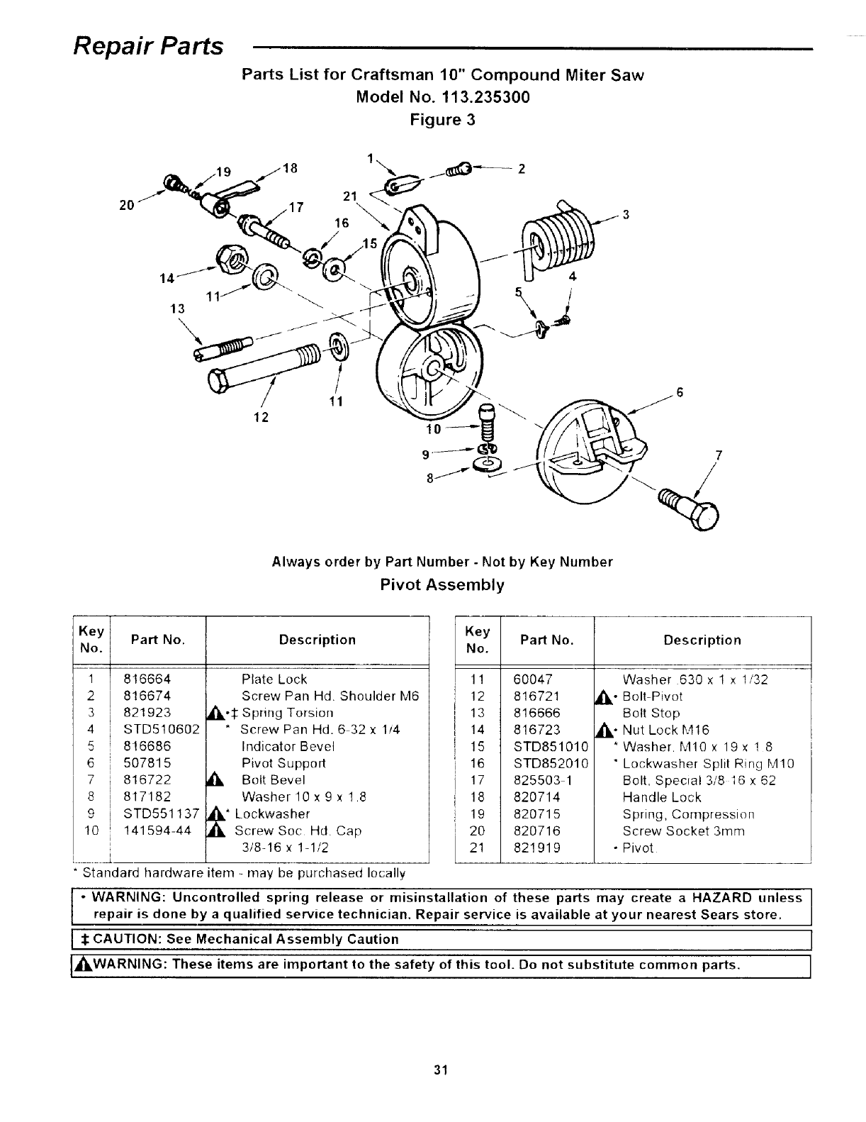
Repair Parts
Parts List for Craftsman 10" Compound Miter Saw
Model No. 113.235300
Figure 3
12
/
11
10
7
/
Always order by Part Number- Not by Key Number
Pivot Assembly
I_ Description
5
6
7
8
9
10
'Y Part No.
).
816664
816674
821923
STD510602
816686
507815
816722
817182
STD551137
141594-44
L•
Plate Lock
Screw Pan Hd. Shoulder M6
_1_':I: Spring Torsion
* Screw Pan Hd. 6 32 x 1/4
Indicator Bevel
Pivot Support
_ Bolt Bevel
WasherlOx9x 1.8
" Lockwasher
Screw Soc Hd. Cap
3t8-16 x 1-1/2
Standard hardware item - may be purchased locally
Key
No.
1!
12
13
14
15
16
17
18
19
20
21
Part No. Description
60047
816721
816666
816723
STD851010
STD852010
825503 1
820714
820715
820716
821919
o
Washer 630 x t x 1/32
Belt-Pivot
Bolt Stop
Nut Lock M16
* Washer. M10 x 19× ! 8
Lockwasher Split Ring M10
Bolt, Special 3/8 16 x 62
Handle Lock
Spring, Compression
Screw Socket 3mm
•Pivot
I" WARNING: Uncontrolled spring release or misinstallation of these parts may create a HAZARD unless
repair is done by a qualified service technician. Repair service is available at your nearest Sears store.
I_: CAUTION: See Mechanical Assembly Caution
I_,WARNING: These items are important to the safety of this tool. Do not substitute common parts.
31
18 19
17
20 21
/
\
t6
23 24
25 26
9
11
13
4
5
"0
r-"
=,,(,t
0
o
m
-_z_
"I
o
oo
n
Z_
(/1
==
15 13 14
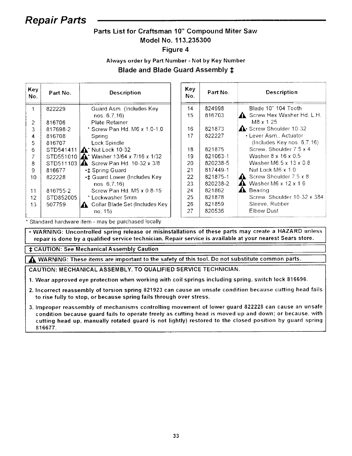
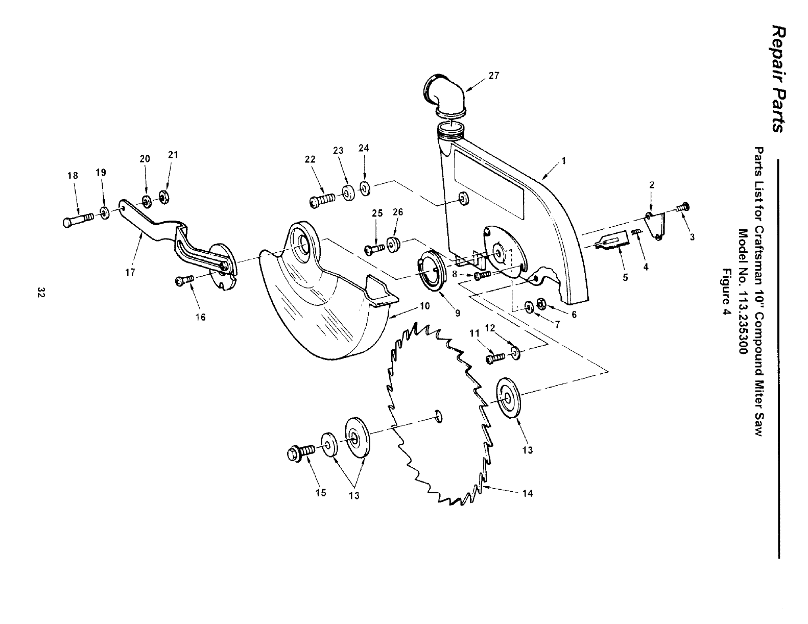
Repair Parts
Parts List for Craftsman 10" Compound Miter Saw
Model No. 113.235300
Figure 4
Always order by Part Number - Not by Key Number
Blade and Blade Guard Assembly :l:
Key IPart No. Description
No.
1822229
2
3
4
5
6
8
9 ._
lO ._
11 816755-2
12 STD852005
13 507759
* Standard hardwareitem
816706
817698-2
816708
816707
STD541411
STD551 010
STD511103
816677
822228
Guard Asm. (Includes Key
nos. 6,7,16)
Plate Retainer
* Screw Pan Hd. M6 x 1.0 1.0
Spring
Lock Spindle
Nut Lock 10-32
Washer 13/64 x 7/16 x 1132
Screw Pan Hd. 10-32 x 3/8
Spring Guard
Guard Lower (Includes Key
nos 6,7,16)
Screw Pan Hd. M5 x 08-15
Lockwasher 5ram
_IL Coltar Blade Set (Includes Key
no. 15)
- may be purchased locally
Key
No.
14
15
16
17
18
19
20
21
22
23
24
25
26
27
Part No. Description
4
824998 I
816703 ,_
821873 _.
822227 •
i
I
821875 I
821063-1
820238-5
817449-1
821875-1 _
820238-2
821862 i
821878
821859
820536
Blade 10" 104 Tooth
Screw Hex Washer Hd. L.H.
M8 x 125
Screw Shoulder 10 32
Lever Asm., Actuator
(Includes Key nos 6,7.16)
Screw, Shoulder 7 5 x 4
Washer 8 x 16 x 0.5
WasherM65x 13x0.8
Nut Lock M6 × 1 0
Screw Shoulder 75 × 8
Washer M6 x 12 x 1 6
Beadng
Screw, Shoulder 10-32 x 384
Sleeve. Rubber
Elbow Dust
• WARNING: Uncontrolled spring release or misinstallations of these parts may create aHAZARD unless
repair is done by a qualified service technician. Repair service is available at your nearest Sears store.
CAUTION: See Mechanical Assembly Caution
WARNING: These items are important to the safety of this tool. Do not substitute common parts.
CAUTION: MECHANICAL ASSEMBLY, TO QUALIFIED SERVICE TECHNICIAN.
1. Wear approved eye protection when working with coil springs including spring, switch lock 816696.
2. Incorrect reassembly of torsion spring 821923 can cause an unsafe condition because cutting head fails
to rise fully to stop, or because spring fails through over stress.
3. Improper reassembly of mechanisms controlling movement of lower guard 822228 can cause an unsafe
condition because guard fails to operate freely as cutting head is moved up and down; or because, with
cutting head up, manually rotated guard is not lightly) restored to the closed position by guard spring
816677.
33

Notes
34

Notes
35
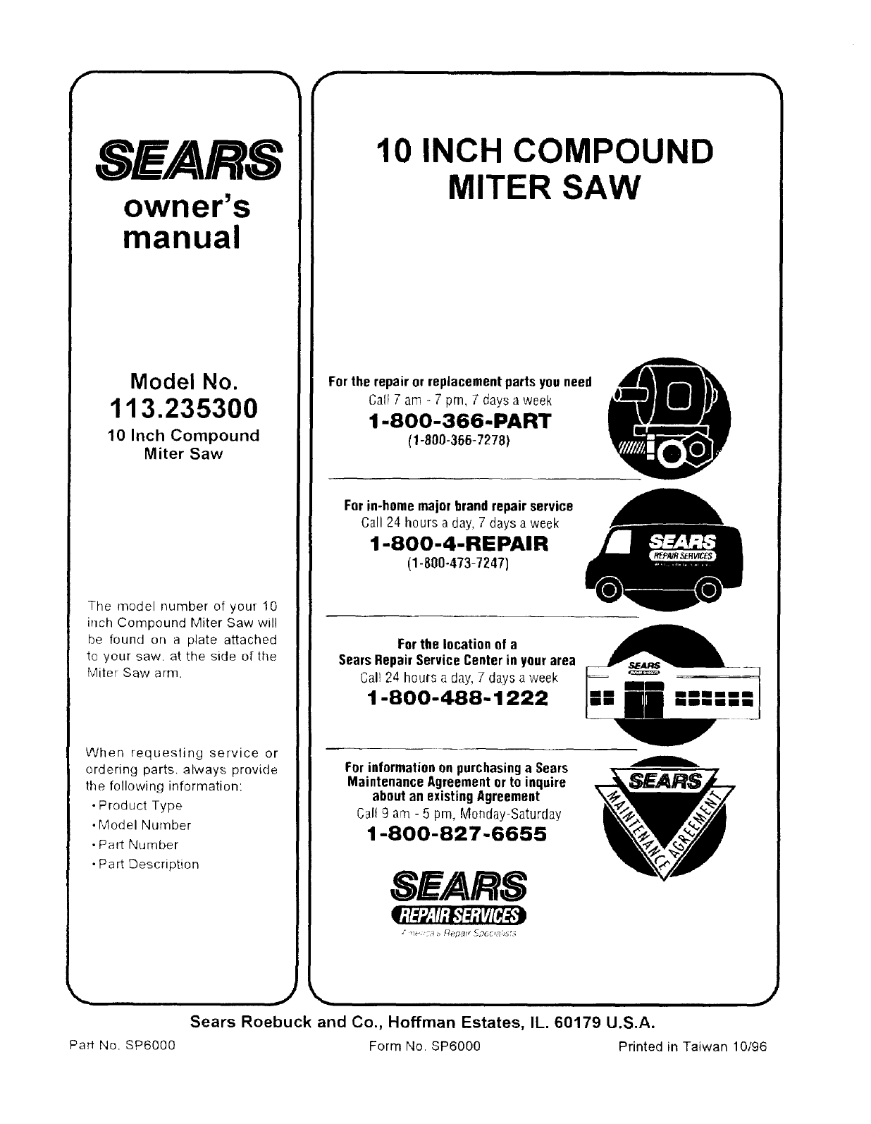
SEARS
owner's
manual
Model No.
113.235300
10 Inch Compound
Miter Saw
The model number of your 10
inch Compound Miter Saw will
be found on a plate attached
to your saw. at the side of the
Miter Saw arm.
When requesting service or
ordering parts, always provide
the following information:
• Product Type
• Model Number
• Part Number
• Part Description
10 INCH COMPOUND
MITER SAW
For the repair or replacement parts you need
Gall Tam -7pm, 7 days a week
1-800-366-PART
fl-800-366-7278)
For in-homemajor brand repair service
Gall 24 hours a day, 7 days a week
I-8OO-4-REPAIR
(1-800-473-7247)
For the location of a
Sears RepairService Center in your area
Cali 24 hours a day,7 days a week
1-800-488-1222
For informationon purchasinga Sears
Maintenance Agreementor to inquire
about an existingAgreement
Carl 9 am - 5 pm, Monday-Saturday
1-800-827-6655
SEARS
Sears Roebuck and Co., Hoffman Estates, IL. 60179 U.S.A.
Part No. SP6000 Form No. SP600g Printed in Taiwan 10/96
