Craftsman 113236400 User Manual SCROLL SAW Manuals And Guides L0804184
CRAFTSMAN Saw Scroll Manual L0804184 CRAFTSMAN Saw Scroll Owner's Manual, CRAFTSMAN Saw Scroll installation guides
User Manual: Craftsman 113236400 113236400 CRAFTSMAN SCROLL SAW - Manuals and Guides View the owners manual for your CRAFTSMAN SCROLL SAW #113236400. Home:Tool Parts:Craftsman Parts:Craftsman SCROLL SAW Manual
Open the PDF directly: View PDF ![]() .
.
Page Count: 26
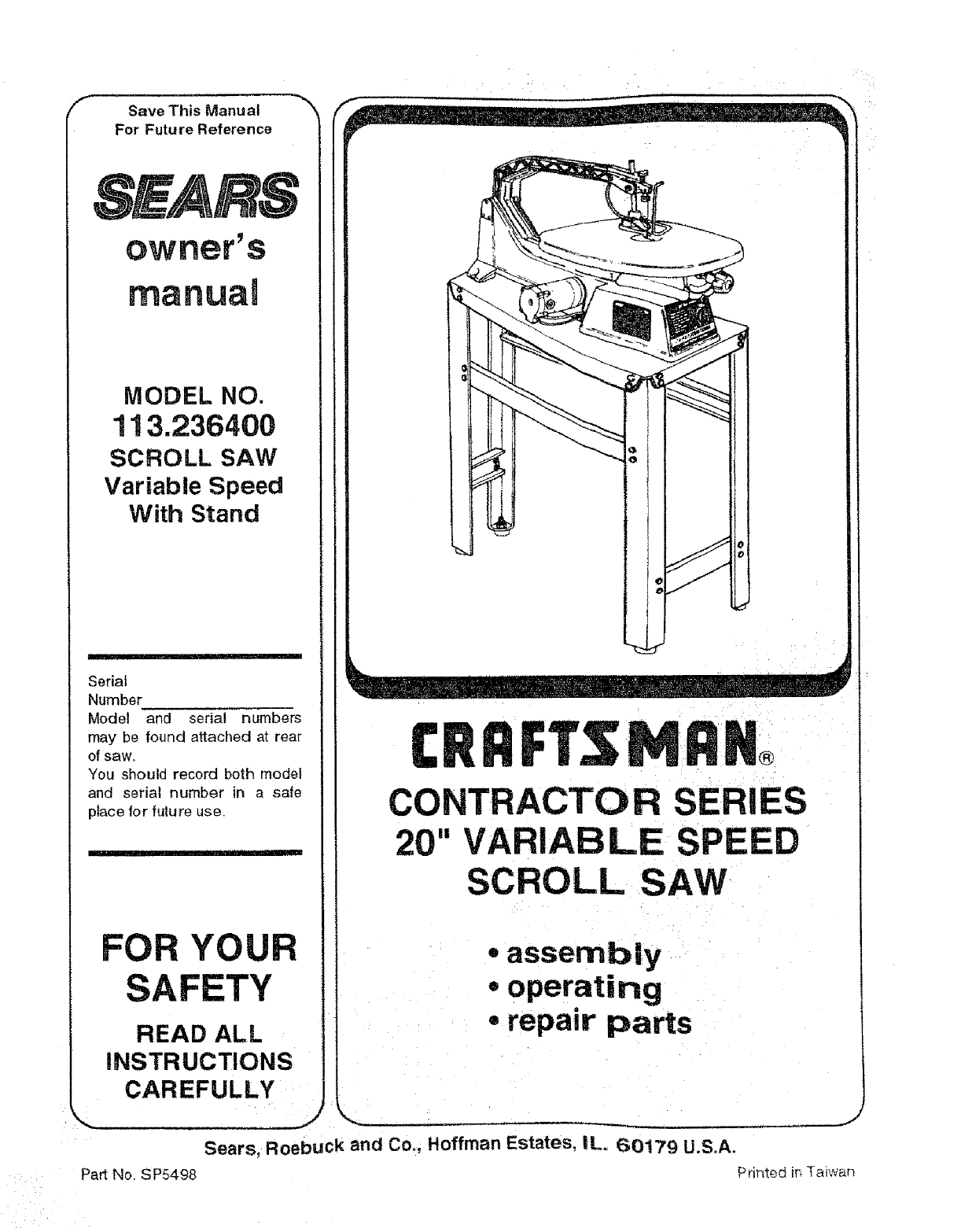
/_ Save This Manual _-'_
For Future Reference
MODEL NO.
113.236400
SCROLL SAW
Variable Speed
With Stand
Serial
Number
Model and serial numbers
may be found attached at rear
of saw.
You should record both model
and serial number in a safe
ptace for future use.
FOR YOUR
SAFETY
READ ALL
iNSTRUCTIONS
CAREFULLY
Pa_ No. SP5498
...)
®
CONTRACTOR SERIES
20" VARIABLE SPEED
SCROLL SAW
-assembly
,,operating
8
*repa=r parts
Sears, Roebuck and Co. Hoffman Estates, iL 60179 U.S.A.
Pnnted in Taiwan
I
J
J
TOOLS
within one year from the date of
THE UNITED STATES, and
free of charge.
'commercial or rental purposes, warranty will apply for ninety days from
.:the:date of purchase, .
-_This warranty applies only while this product is in the United States.
you specific legal rights and you may also have other rights which vary from state
Sears, Roebuck and Co., D817 WA Hoffman Estates, IL. 60179
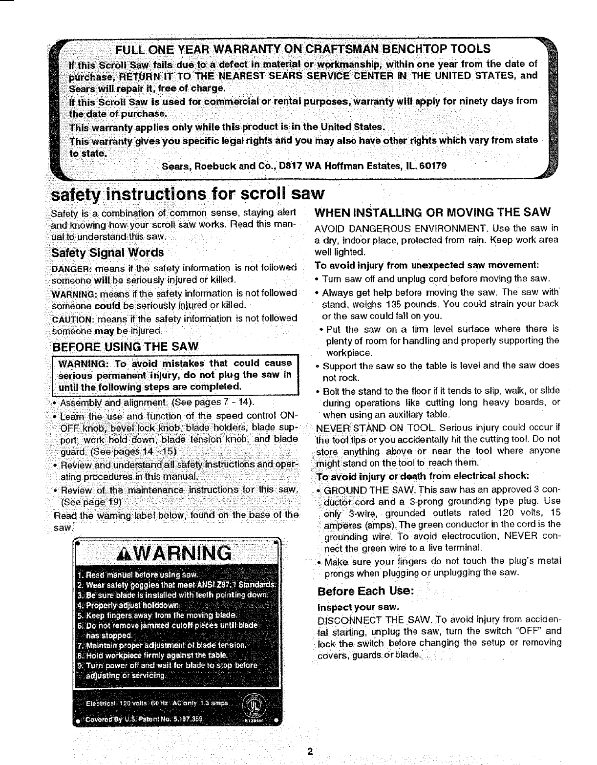
safety instructions for scroll saw
-Safety is a combination of Common sense, staying a|ed WHEN INSTALLING OR MOVING THE SAW
"and knowing how your scroll saw works. Read this man-
ualto understand this saw.
Safety Signal Words
DANGER: means if the safety information is not followed
someone will be seriously injured or killed.
WARNING: means if the safety information is not followed
-someone could be seriously injured or killed.
CAUTION: means if the safety information is not followed
someone may be injured.
BEFORE USINGTHE SAW
[WARNING: TO avoid mistakes that could cause I
tsetious permanent injury, do not plug the saw in !
]until the following steps are completed.
., Assembly and alignment. (See pages 7 - 14).
-. Leamtlie_:use_ and:function of the speed control ON-
AVOID DANGEROUS ENVIRONMENT. Use the saw in
a dry, indoor place, protected from rain. Keep work area
wel! lighted.
To avoid injury from unexpected saw movement:
•T_m saw off and unplug cord before moving the saw.
• Always get help before moving the saw. The saw with
stand, weighs 135 pounds. You could strain your back
or the saw could fall on you.
• Put the saw on a firm level surface where there is
plenty of room for handling and properly supporting the
workpiece.
o Support the saw so the table is level and the saw does
not rock.
• Boll the stand to the floor if it tends to slip, walk, or slide
during operations like cutting long heavy boards, or
when using an auxiliary table.
guard,(Seepages i4_-1i5) ,;-; ......... i_ _ _- - '_..
-Review ahdUhderstandatt,S_,fety_irist_cti0'ns!ar_d opei ;_
ating:procedures in:this hladuai.-: _::- :.:_ :i: ,:
•Review 0f the maintenance :instrQctioi_s for this saw.
(Seep,_ge_9):• :::' " : : :_
Read the warning label below, found on the base of the
saw.
OFE ik'iiob_;beVe|:_10Ckkdbb,=bladeholders, blade sup- NEVER STAND ON TOOL. Serious injury could occur it
p0rt; h0ia:a0wn,blade:tension -knob, and blade the tool tips or you accidentally hit the cutting tool. Do not
store anything above or near the tool where anyone
might stand on the tool to reach them.
To avoid injury or death from electrical shock:
, GROUND THE SAW. This saw has an approved 3 con-
ductor cord and a 3-prong grounding type plug. Use
........... grounded outlets rated 120 volts. 15
amperes (amps). The green conductor in the cord is the
grounding wire. To avoid electrocution, NEVER con-
nect the green wire to a live terminal.
•Make sure your fingers do not touch the plug's metal
prongs when plugging or unplugging the saw,
Before Each Use:
Inspect your saw.
DISCONNECT THE SAW. To avoid injury from acciden-
tal starting, unplug the saw, turn the switch "OFF" and
lock the switch before changing the setup or removing
covers, guards or blade.
_' i _ i_ _ ..... _i..... :
CHECK FOR DAMAGED PARTS. Check for:
•Alignment of moving pads.
•Binding of moving parts.
° Broken parts.
° Stable mounting and
- Any other conditions that may affect the way the saw
works.
if any part is missing, bent or broken in any way, or any
electrical part doesn't work properly, turn off and unplug
the saw, REPLACE damaged, missing or failed parts
before using the saw again, Keep Guards In Place and
in working order.
MAINTAIN TOOLS WITH CARE. Keep the saw clean for
best and safest performance. Follow instructions under
"Maintenance",
REMOVE ADJUSTING KEYS AND WRENCHES from
toot before turning it on.
To avoid injury from jams, slips or thrown pieces:
- Choose the right size and style blade for the material
and the type of cutting you ptan todo.
° USE ONLY RECOMMENDED ACCESSORIES. (See
page 20). Consult this owners manual for recom-
mended accessories. Fot]ow the instructionsthat come
with the accessories. The. use of improper accessories
may cause risk of injury to person.
-Make sure the blade teeth point downward, toward the
table.
• Make sure the b_adetension is properly adjusted,
=Make sure the bevel lock knob is tight and no parts
have excessive play.
•To avoid accidental blade contact, minimize blade
breakage and provide maximum blade support, always
adjust the blade hold-down and blade guard to just
clear the workpiece,
•KEEP WORK AREA CLEAN. Cluttered areas and
benches invite accidents. Floor must not be slippery.
To avoid burns or other fire damage, never use the saw
near flammable liquids, vapors or gases.
PLAN AHEAD TO PROTECT YOUR EYES,
HANDS, FACE AND EARS:
KNOW YOUR SAW, Read and understand the owners
manual and labels affixed to the too!. Learn its application
and limitations as well as the specific potential hazards
peculiar to this tool.
To avoid injury from accidental sontact with moving parts,
don't do layout, assembly, or setup work on the saw while
any parts are moving.
AVOID ACCIDENTAL STARTING. Make sure switch is
"OFF" before plugging saw into a power outlet.
Plan Your Work.
•USE THE RIGHT TOOL. Don_ force too! or attachment
to do ajob it was not designed to do.
•UsethiS scroll s#,w to cut only wo0d, wo0diike products,
plastics and nonferrous: metals .... .
CAUTION: This :Saw:i_ NOT designed for cutting
ferrous metals like it0n 0r steel When cutting non-
ferrous metals (brass, copper and aluminum, etC.),
metal shavings can react with wood dust and start
a fire. To avoid this:
• Disconnect any type of dust collecting hose from
the saw.
•Remove al| traces of wood dust from on and
around the saw.
• Remove all metal shavings from on or around the
saw before sawing wood again.
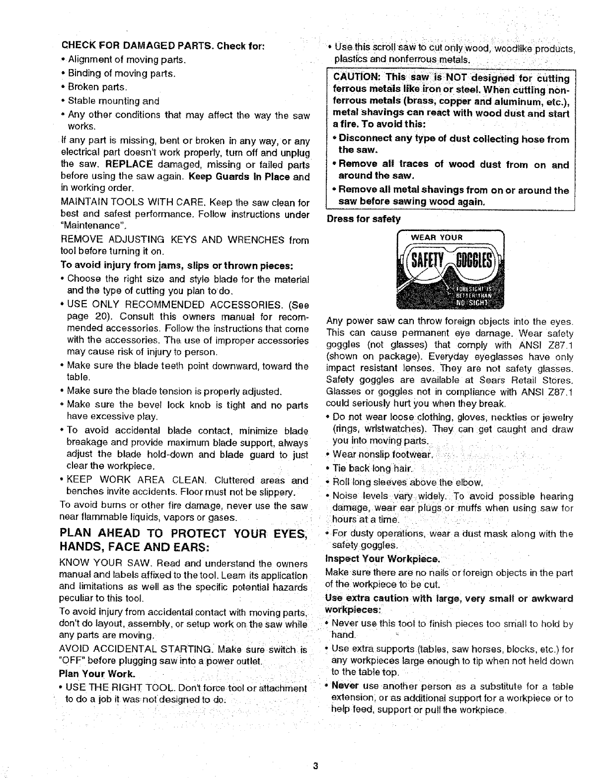
Dress for safety
Any power saw can throw foreign objects into the eyes.
This can cause permanent eye damage. Wear safety
goggles (not glasses) that comply with ANSI Z87.1
(Shown on package). Everyday eyeglasses have only
impact resistant lenses. They are not safety glasses.
Safety goggles are available at Sears Retail Stores.
Glasses or goggles not in compliance with ANSI Z87.1
could seriously hurt you when they break.
• Do not wear loose cJothJng, gloves, neckties or jewelry
(rings, wristwatches). They can :get caught and draw
you into moving pads.
• Wear nons}ip footwear,
°Tie back lor_ghair.
• Roll tong sleeves above the elbow.
° Noise levels vary widely, To avoid possible hearing
damage, wear ear plugs or muffs when using saw for
hours at a time.
•For dusty operations, wear a dust mask along with the
safety goggles.
Inspect _'our Workpiece.
Make sure there are no nails or foreign objects in the par_
of the workpiece to be cut.
Use extra caution with large, very small or awkward
workpieces:
•Never use this toot to finish pieces too smelt to hotd by
hand.
, Use extra supports (tables, saw horses, blocks, etc.) for
ar_yworkpieces large enough to tip when not held down
to the table top.
-Never use artother person as a substitute for a table
extension, or as additional support for a workpiece or to
help teed, support or puff the workpiece
safetyinstructions for scroll saw
When c[itt _g:irreg;u|adY-shaped workpieces plan your Before starting Your cut watch the saw while it runs. If it
work sO it Will dot pii_ch the blade. A piece:of, molding, makes an unfamiliar noise or vibrates a lot, stop immedi-
-f0i; examp'le must lay flat orbe held bya f_ture Or jig ately Turn the saw off. Unplug the saw. Do not restart
that Willnot let :ittW st, rock oi slip whilebeihg cut, until lindingand correcting the problem.
, P_e_:sUpport round:materiai such as dowel rods, or KEEP CHILDREN AWAY. Keep al_ visitors a safe dis-
tul_ing__ey_have _ tendency to roll during a cut, _using tance from: the :saw. Make sure bystanders are clear o!
the bl_e to bite. To avoid this, always use a "V" block. : the Saw and workpiece.
-Cut onlyone workpiece at a time.
, Clear, everything except the workpiece and related
-Support devices off the table before turning the saw on.
Plan the way you will hold the workpiece from start
to finish.
Do not hand hold pieces so small that your fingers will go
under the work hold down. Use jigs or fixtures to hold the
work and keep your hands away from the blade.
Avoid awkward operations and hand positions where a sud-
den slip could cause fingers or hand to move into the blade.
Don't Overreach. Keep good footing and balance.
Keep your face and body to one side oI sawb{ade, out of
line-with a possible thrown piece:
SECURE WORK. Use clamps to hold work when practi-
cal. It!s often safer than using your hand, and frees both
hands to operate the too!.
Avoid awkward operations and hand positions where a sud-
den slip could cause fingers or hand to move into the blade.
DON'T OVERREACH. Keep good footing and balance.
Keep your face and body to one side of the blade, out of
line with a possible thrown piece if the blade should break.
WHENEVER SAW IS RUNNING
DON'T FORCE TOOL. It wil!do the job better and safer at its
designed rate. Feed the workpiece into the saw blade only
fast enough to let it cutwithout bogging down or binding.
Before freeing any jammed material:
*Push switch "OFF".
......... all moving parts to stop.
oUnplug the saw.
When backing up the workpiece, the blade may bind
in the kerr (cut). This is usually caused by sawdust
clogging up the kerr. If this happens:
- Turn switch "OFF".
, Wait for allmoving parts to stop.
°Unplug the saw
oRemove the blade from the blade holders.
-Remove workpiece with blade from the table, Remove
blade from workpiece.
Before removing loose pieces from the table, turn
saw off and wait for all moving parts to stop.
BEFORE LEAVING THE SAW
Wait for all moving parts to stop.
MAKE WORKSHOP CHILD PROOF. Unplug the saw.
Lock the shop or on/off knob. Store the key away from
children and others not qualified to use lhe tool.
cause asevere injury,
•i! rl
electrical connections
DANGER: To avoid electrocution:
1. Use only identical replacement parts when seP
vicing. Servicing should be performed by a
qualified service technician.
2. Do not use in rain or where floor is wet.
This tool is intended for indoor residential use
only.
tWARNING Do not permit fingers to touch the ter- I
I minals of plug when installing or removing the I
Iplug toot from the outlet, i
I If power cord is worn or cut, or damaged in any
I way, have it replaced immediately.
NOTE: The plug supplied on your too! may not fit into the
outlet you are planning to use. Your local electrical Code
may require slightly different power cord plug.connec-
tions. It these differences exist refer to and make the
-proper adjustments per your local code before your tool
is pluggea in and turned on.
In the event of a malfunction or breakdown, grounding
provides a path of least resistance for electnc current to
reduce the risk of electric shock. This tool is equipped
with an electric cord having an equipment grounding con-
ductor and a grounding plug, as shown. The plug must
be plugged into a matching outlet that is properly
installed and grounded in accordance with all local codes
and ordinances.
Do not modify the plug provided. If it wil not tit lhe outlet.
have the proper outlet installed by a qualified electrician.
A temporary adapter may be used to connect this plug to
a 2-pole outlet as shown, if a properly grounded outlet is
not available. This temporary adapter should be used
only until a properly grounded outlet can be installed by a
qualified electrician. The green colored rigid ear. tug and
the like, extension from the adapter must be connected to
apermanent ground such as a properly grounded outlet
box.
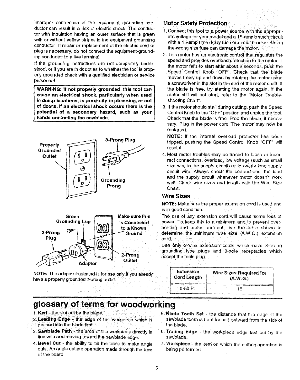
Improper connection of the equipment grounding con-
ductor can result in a risk of electric shock. The conduc-
tor with insulation having an outer surface that is green
with or without yellow stripes is the equipment grounding
conductor. If repair or replacement of the electric cord or
plug is necessary, do not connect the equipment-ground-
ing conductor to a live terminal.
If the grounding instructions are not completely under-
stood, or if you are in doubt as to whether the tool is prop-
erly grounded check with a qualified electrician or service
)ersonnel,
WARNING: If not properly grounded, this tool can
cause an electrical shock, particularly when used
in damp locations, in proximity to plumbing, or out
of doors. If an electrical shock occurs there is the
potential of a secondary hazard, such as your
hands contacting the sawblade.
Properly
Grounded
Outlet
\\O
3-Prong Plug
Grounding
Prong
Motor Safety Protection • :
!. Connect this too! to apower source with the appropri-
ate voltage for your model and a 15-amp branch circu t
with a 15-amp time delay fuse or circuit breaker. Using
the wrong size fuse can damage the motor.
2. This motor has an electronic control that regulates the
speed and prov des overload protection to the motor, if
the motor fails to start after about 2 seconds push the
Speed Control Knob "OFF'. Check that the blade
moves freely up and down by rotating the motor using
a screwdriver in the slot in the end of the motor shaft. It
the blade is free, try starting the motor again, if the
motor still will not start, refer to the "Motor Trouble-
shooting Chart".
3. If the motor should stall during cutting, push the Speed
Control Knob to the "OFF" position and unplug the tool.
Check that the blade is free. Free the blade, if neces-
sary. Plug in the power cord The motor may now be
restarted.
NOTE: If the internat overload protector has been
tripped, pushing the Speed Control Knob "OFF" will
reset it.
4. Most motor troubles may be traced to loose or incor-
rect connections, overload, low voltage (such as small
size wire in the supply circuit) or to overly long supply
circuit wire. Always check the connections the toad
and the supply circuit whenever motor doesn't work
well. Check wire sizes and length with the Wire Size
Chart.
Wire Sizes
Green
Grounding
3-Prong _"
Plug
\
Adapter
Make sure this
is Connected
to a Known
2-Prong
Outlet
NOTE: Make sure the proper extension cord is used and
is in good condition,
The use of any extension cord wi!l cause some loss ot
power. To keep this to a minimum and to prevent over-
heating and motor bum-out, use the table shown to
determine the minimum wire size (A.W.G_) extenston
cord.
Use 0nly 3_wire extension cords which have 3-prong
grounding type plugs and 3-pole receptacles which
accept the tools plug.
Extension !Wire Sizes Required for
!
NOTE: The adapter illustratedis for use only if you already Cord Length t(A.W,G.)
have a properly grounded 2oprong outlet. __
0-50 Ft. _[ 16
tm
glossary of erms for woodworking
!. Kerr - the Slotcut by the blade, i . 5. Blade Tooth Set - the distance that the edge ot the
2. Leading Edge -the edge of the workpiece which =s
pushed into the blade first.
3. Sawblade Path -the area of the workpiece directly in
line with and moving toward the sawblade edge.
4. Bevel Cut - the ability to tilt the table to make angle
cuts, An angle cutting operation made through the face
of the board
sawblade tooth is bent {or set) outward from the side of
the blade_
6. Trailing Edge - the workpiece edge test cut by the
sawblade.
7. Workpiece- the item on which the cutting operation is
being pedormed.
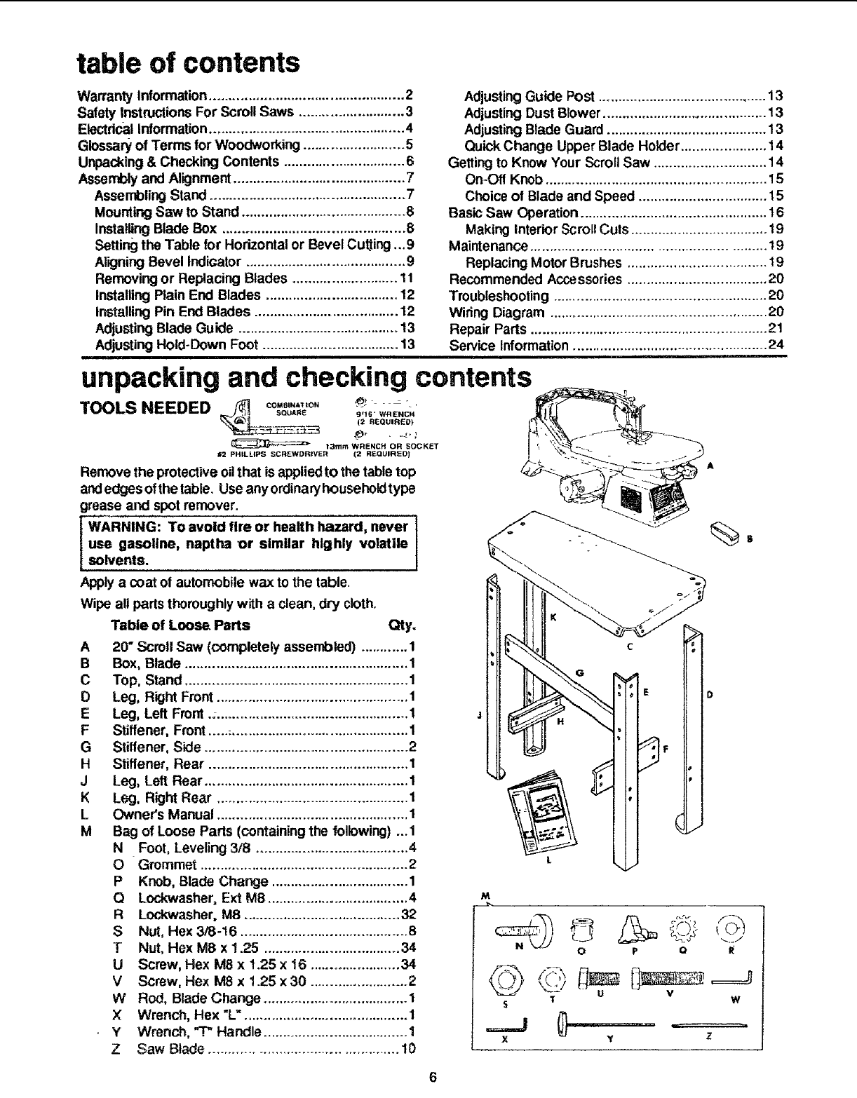
table of contents
Warranty Information .................................................. 2
Safety Instructions For Scroll Saws ........................... 3
Electrical Information.................................................. 4
Glossary of Terms for Woodworking .......................... 5
Unpacking & Checking Contents ............................... 6
Assen_ly and Alignment ............................................ 7
Assembling Stand .................................................. 7
Mounting Saw to Stand .......................................... 8
Installing Blade Box ............................................... 8
Setting the Table for Horizontal or Bevel Cutting,.. 9
Aligning Bevel Indicator ......................................... 9
Removing or Replacing Blades ........................... 11
Installing Plain End Blades .................................. 12
Installing Pin End Blades ..................................... 12
Adjusting Blade Guide ......................................... 13
Adjusting Hold-Down Foot ................................... 13
Adjusting Guide Post ........................................... 13
Adjusting Dust Blower .......................................... 13
Adjusting Blade Guard ......................................... 13
Quick Change Upper Blade Holder ...................... 14
Getting to Know Your Scroll Saw ............................. 14
On-Off Knob ......................................................... 15
Choice of Blade and Speed ................................. 15
Basic Saw Operation ................................................ 16
Making Interior Scroll Cuts ................................... 19
Maintenance ........................................................... t9
Replacing Motor Brushes .................................... 19
Recommended Accessories .................................... 20
Troubleshooting ....................................................... 20
Wiring Diagram ........................................................ 20
Repair Parts ............................................................. 21
Service Information .................................................. 24
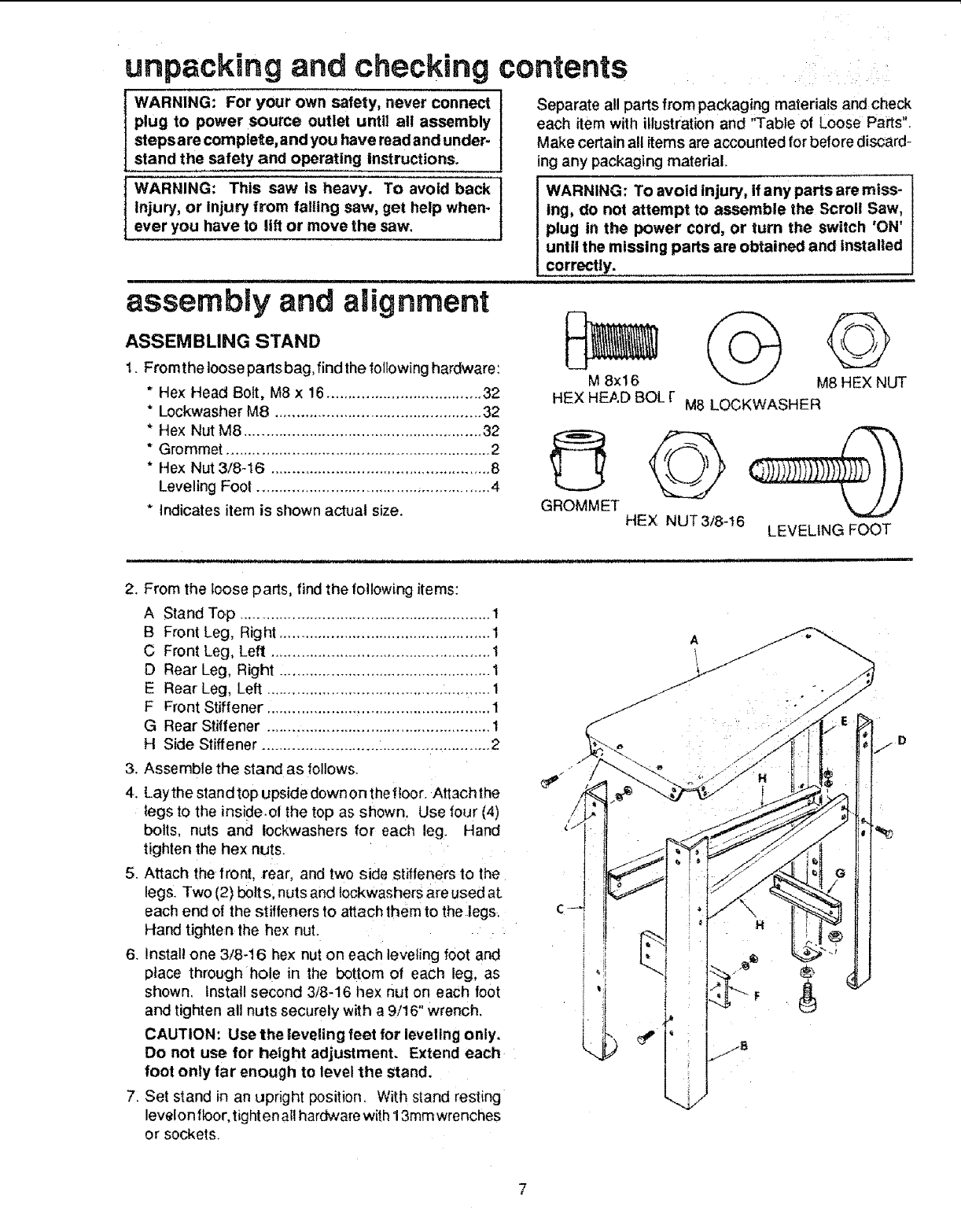
unpacking and checking contents
TOOLS NEEDED /_ CD.8,.._,o. '_ _ _ -,
_QUARE 9116 ' WRENCH
(2 REQUIRED}
t3mm WRENCH OR 5DCKET
#2 PHILLIPS SCREWDRIVER (2 REQUIRED)
Remove the protective oil that is applied to the table top
andedgesof thetable. Use any ordinan/householdtype
grease and spot remover.
tWARNING: TO avoid fire or health hazard, never t
use gasoline, naptha or similar highly volatile I
solvents.
Apply a coat of automobile wax to the table.
Wipe all parts thoroughly with a clean, dry cloth.
Table of Loose Parts Qty.
A20" Scroll Saw (completely assembled) ............ 1
B Box, Blade ......................................................... 1
C Top, Stand ......................................................... 1
DLeg, Right Front ................................................. 1
ELeg, Left Front ................................................... 1._
F Stiffener, Front ................................................... 1
G Stiffener, Side .................................................... 2
H Stiffener, Rear ................................................... 1
J Leg, Left Rear .................................................... 1
K Leg, Right Rear ................................................. 1
L Owner's Manual ................................................. 1
MBag of Loose Pads (containing the following) ... 1
NFoot, Leveling 3/8 ....................................... 4
O Grommet ..................................................... 2
P Knob, Blade Change ................................... 1
Q Lockwasher, Ext M8 .................................... 4
R Lockwasher, M8 ........................................ 32
S Nut, Hex 3/8-16 ........................................... 8
T Nut, Hex M8 x t .25 ................................... 34
U Screw, Hex M8 x 1.25 x 16 ....................... 34
VScrew, Hex M8 x 1.25 x 30 ......................... 2
WRod, Blade Change ..................................... 1
X Wrench, Hex "L". ......................................... 1
Y Wrench, "T" Handle ..................................... 1
Z Saw Blade ............................................... 10
M
op o I_
\_i/ u v
T W
S
.=__J
xZ
unpacking and checking contents
WARNING: For your own safety, never connect
plug to power source outlet until all assembly
steps are complete, and you have read and under-
stand the safety and operating instructions.
WARNING: This saw is heavy. To avoid back
Injury, or Injury from falling saw, get help when-
ever you have to Uft or move the saw.
assembly and alignment.............................
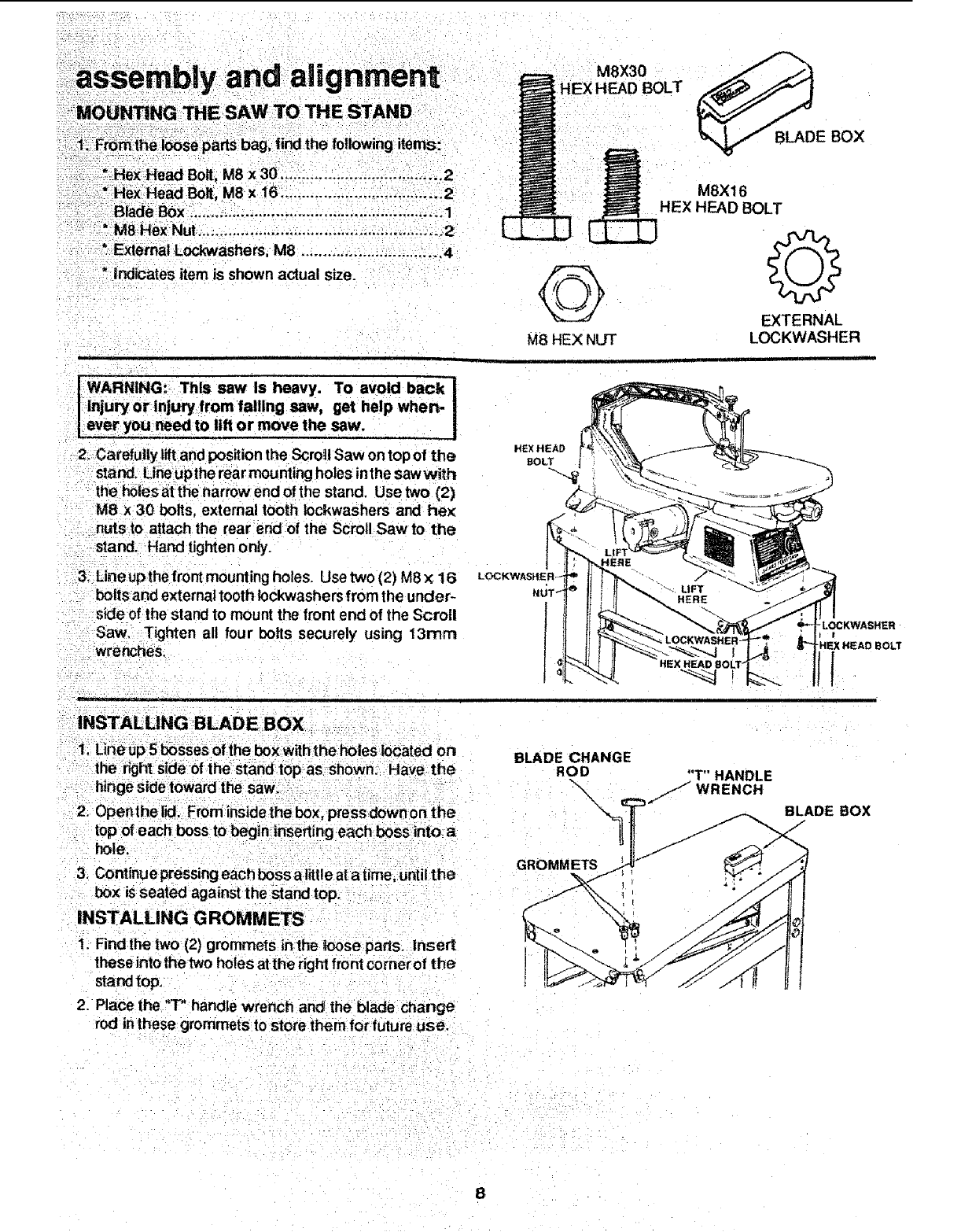
ASSEMBLING STAND _
1. Fromthe loose parts bag, find the following hardware: M 8x !6
Separate all parts from packaging materials and check
each item with illustration and "Table of Loose Parts".
Make certain all items are accounted for before discard-
ing any packaging material.
IWARNING: To avoid injury, if any parts are miss-
Ing, do not attempt to assemble the Scroll Saw,
plug in the power cord, or turn the switch 'ON'
until the missing parts are obtained and Installed
corre 'ti,y.,............. ,ll
©
M8 HEX NUT
* Hex Head Bolt, M8 x 16.................................... 32
* Lockwasher M8 ................................................ 32
* Hex Nut M8 ....................................................... 32
*Grommet ............................................................. 2
" Hex Nut 3/8-16 ................................................... 8
Leveling Foot ...................................................... 4
*Indicates item is shown actual size.
HEX HEAD BOL I- M8 LOCKWASHER
O
GROMMET
HEX NUT3/8-16 LEVEUNG FOOT
2. From the loose parts, find the following items:
A Stand Top .......................................................... 1
B Front Leg, Right ................................................. 1
C Front Leg, Left ................................................... 1
D Rear Leg, Right ................................................. 1
E Rear Leg, Left .................................................... 1
F Front Stiffener .................................................... 1
G Rear Stiffener .................................................... 1
H Side Stiffener ..................................................... 2
3. Assemble the stand as follows.
4. Laythe standtop upside downon the floor. Attachthe
legs to the inside.ol the top as shown. Use four (4)
bolts, nuts and Iockwashers for each leg. Hand
tighten the hex nuts.
5. Attach the front, rear, and two side stiffeners to the
legs. Two (2) bo_s, nuts and lockwashers are used at,
each end of the stiffeners to attach them to the legs.
Hand tighten the hex nut.
6. Install one 3/8-16 hex nut on each leveling foot and
place through hole in the bottom of each leg, as
shown. Install second 3/8,16 hex nut on each foot
and tighten all nuts securely with a 9/16" wrench.
CAUTION: Use the leveling feet for leveling only.
Do not use for height adjustment. Extend each
foot only far enough to level the Stand.
7: Set stand in an upright position, With stand resting
level on floor, fighten al! hardwarewith13mm wrenches
or sockets.
®
d alignrnent
aSSembiy+ an
MOUNTING THE SAW TO THE STAND
...... •.... +
Y.+:i:i_:Fromihb loose parts bag, 1indthe following items:
: : *+Hex:Head Bolt:,M8 x30 .................. ...... 2
:_ * Hex Head Bolt, M8 x 16 ..................... :............ ,..2
+++B_e Box+......,.........:............................i.......:+ol
•"M8 Rex Nut..... ,........... .........,+...+..,..+...+..+.-+..... 2
MSX30
HEX HEAD BOLT
M8X16
HEX HEAD BOLT
* External Lockwashers, M8 ............ _................... 4
*indicates item is shown actual size.
I WARNING: This saw Is heavy. To avoid back !
I Injury or Injury from falling saw, get help wherv
lever youneedto lift or move the saw,
2; Carefully Uftand positionthe Scroll Saw on top of the
stand. Lineupthe rear mountingholes inthe sawwith
tt_e_01esat the narrow end of the stand, Use two (2)
M8 x30 bolts, external tooth lockwashers and he>_
nuts to attach the rear end of the Scroll Saw to the
stand. -Hand tighten only.
3: Line up the front mount ing holes+ Use two (2) M8 x16
boltsand external tooth Iockwashers from the under-
"sideof the stand to mount the front end of the Scroll
Saw, Tighten all four bolts securely using _3rnrn
wrenches.
:: , • ::.
,i i
;_+INSTALLING BLADE BOX + _+
+i; Line up 5 boSSes 0f=ihebox Withthe holes located on
the dght side of the stand topas stlown: :Have the
hinge Sidetoward the saw.. -+
2. Openthe lid. From inside the box, press down on the
top of each boss to begin lilserting each boss into_ a
hole;
3, Continue pressing each boss alittle at a time, until the
box is seated against the stand top+ - -
INSTALLING GROMMETS
©
M8 HEX NUT
O
EXTERNAL
LOCKWASHER
HEXHEAD
BOLT
BLADE CHANGE
ROD
\\
GROMMETS
"T" HANDLE
/WRENCH
!
I
BLADE BOX
1. Find the two (2) grommets lnthe k)ose parts. Insert
theseintothe two holes at the right front comerof the
stand top+
2. Place the "T" handle wrench and theblade change
rod in these grommets to store them for future use.
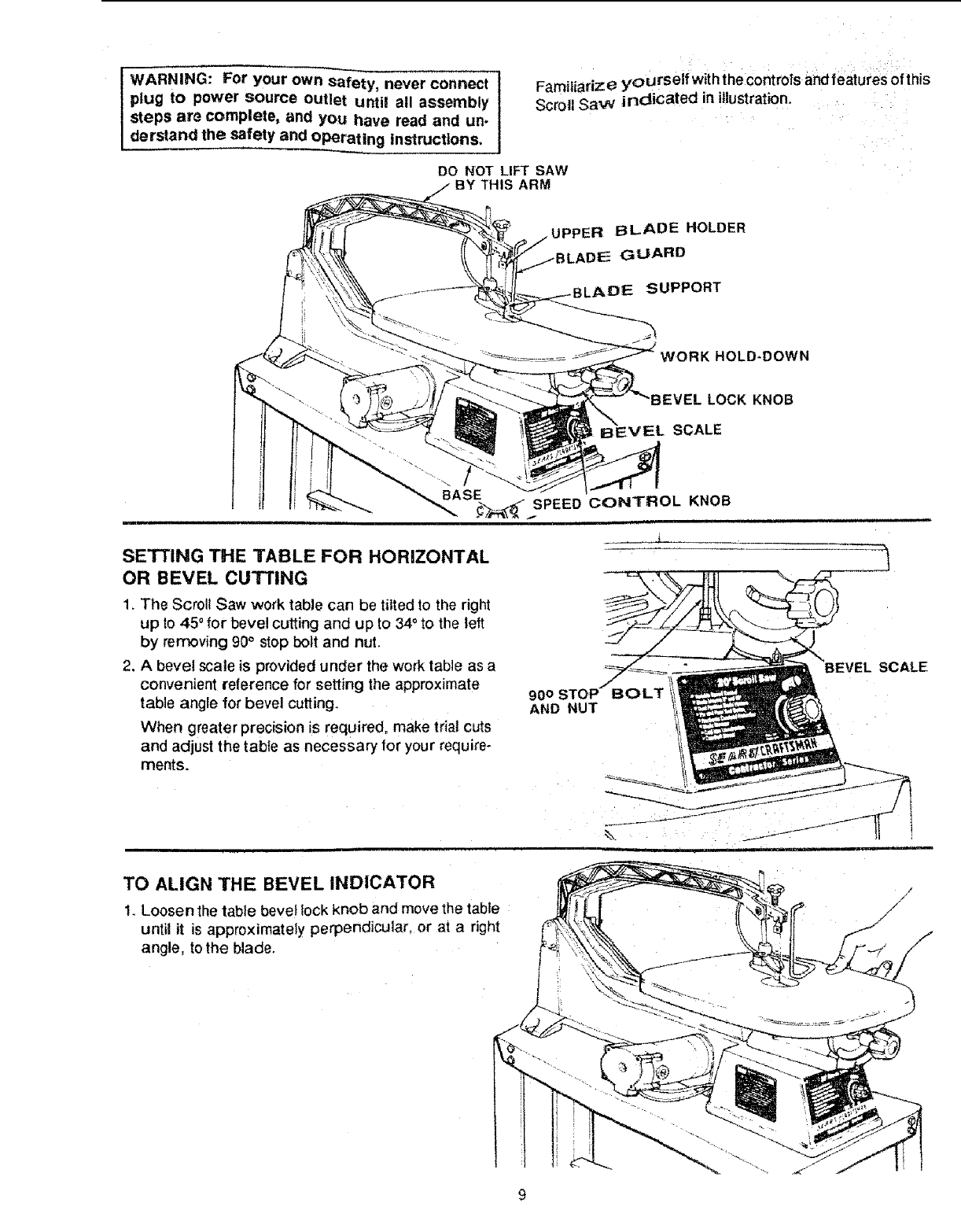
WARNING: For your own safety, never connect
plug to power source OUtlet untll all assembly
steps a_e complete, and you have read and un-
derstand the safety and operating instructions,
Familiarize yourself with thecontr0fs and feaiures of this
Scroll SaW indicated in illustration. ::
DO NOT LIFT SAW
BY THIS ARM
UPPER BLADE HOLDER
_ADEE GUARD
DE SUPPORT
HOLD-DOWN
:VEL LOCK KNOB
_.VEL SCALE
_._...SPEED CONTROL KNOB
i i
SETTING THE TABLE FOR HORIZONTAL
OR BEVEL CUTTING
1. The Scroll Saw work table can be tilted to the right
up lo 450 for bevel cutting and up to 34° to the left
by removing 90° stop bolt and nut.
2, A bevel scale is provided under the work table as a
convenient reference for setting the approximate
table angle for bevel cutting.
When greater precision is required, make trial cuts
and adjust the table as necessary for your require-
ments.
900 STOP BOLT
AND NUT
lEVEL SCALE
TO ALIGN THE BEVEL INDICATOR
1. Loosen the table bevel lock knob and move the table
untiJ it is approximately perpendicular, or at a right
angle, to the blade.
/
/
/
//
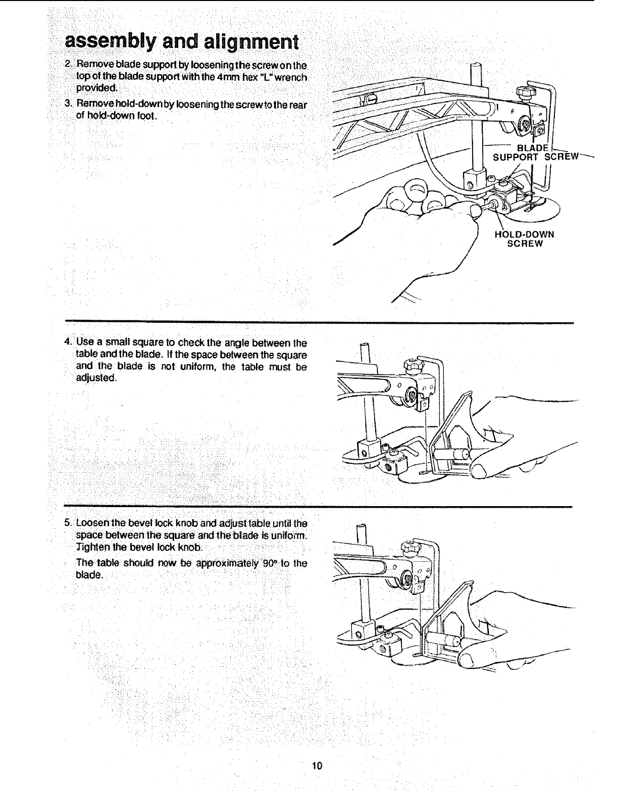
provided.
3. Remove hold-down by iooseningthe screwtolhe rear
of hold-down foot.
SUPPORT SCREW "--_"
/
/
/
HOLD-DOWN
SCREW
4. Use a small square to check the angle between the
table and the blade. If the space between the square
and the blade is not uniform, the table must be
adjusted,
5. Loosen the bevel lock knob and adjust tabte untilthe
space between the square and theblade is unifo;m.
Tighten the bevel lock knob.
The table should now be approximately 90oto the
blade,
10
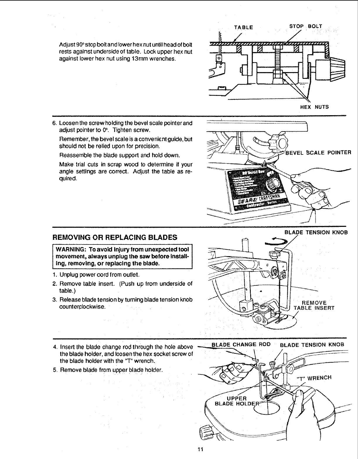
Adjust 90° stop bolt and lower hex nut until head of bolt
rests against underside of table. Lock upper hex nut
against lower hex nut using 13ram wrenches.
TABLE STOP BOL T
HEX NUTS
iiiiiiiii, _ ,,,i,l.lmlll
6. Loosenthe screw holding the bevelscaie pointerand
adjust pointer to 0°, Tighten screw. \
Remember, the bevel scale isa convenicnt guide, but
should not be relied upon for precision.
Reassemble the blade support and hold down.
Make trial cuts in scrap wood to determine ff your
angle settings are correct. Adjust the table as re-
quired.
EVEL _CALE POINTER
REMOVING OR REPLACING BLADES
! I
movement, always unplug the saw before Install-
Ing, removing, or replacing the blade.
t. Unplug power cord from outlet.
2. Remove table insert. (Push up from underside of
table.)
3. Release blade tension by turning blade tension knob
counterclockwise.....
!
BLADE TENSION KNOB
4+ Insert the blade change rod through the hole above _GE ROD
the blade holder, and loosen the hex socket screw of
the blade holder with the "T" wrench.
5_ Remove blade from upper blade holder.
iii
BLADE TENSION KNOB
"T" WRENCH
11
assembly and a|ignrnent
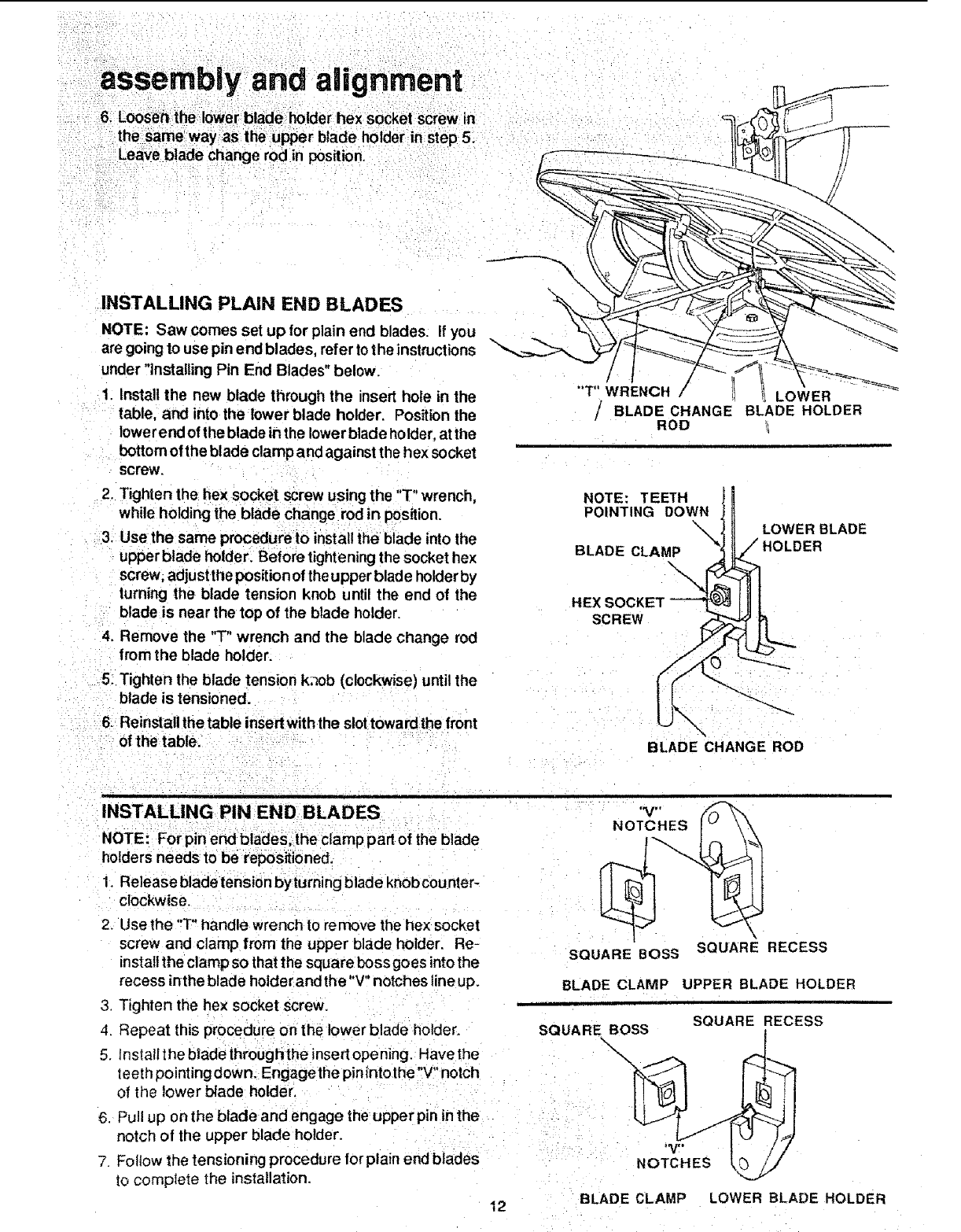
6. Loosen the lower blade holder hex socket screw in
INSTALLING PLAIN END BLADES
NOTE: Saw comes set up for plain end blades. If you
are going lo use pin end blades, refer tothe instructions
under "installing Pin End Blades" below.
1. install the new blade through the insert hole in the
table, and into the lower blade holder. Position the
lowerend of the blade in the lower blade holder, atthe
bOttom of the blade clamp and against the hex socket
screw.
2. Tighten the hex socket screw using the "T" wrench,
while holding the blade change rod in position.
-3. Use the same procedure to installthe blade into the
upper blade holder, Before tightening the socket hex
screw,adjust the positionof the upper blade holderby
turning the blade tension knob until the end of the
blade is near the top of the blade holder.
4, Remove the "T" wrench and the blade change rod
from the blade holder.
5: Tighten the blade tension k,7ob (clockwise) until the
blade is tensioned.
6. Reinstall thetable insertwith the slottoward the front
of the table.
/
"T" WRENCH /_LOWER
// BLADE CHANGE BLADE HOLDER
ROD _1
NOTE: TEETH
POINTING DOWNI\\
BLADE CLAMP
\
LOWER BLADE
HOLDER
SC REW
BLADE CHANGE ROD
INSTALLING PIN END BLADES
NOTE_ For pin end blades_the clamp part of the blade
holders needs to be repositioned.
1. Release blade tension byturning blade knobcounter-
clockwise.
2. Use the "T"handle wrench to remove the he×socket
screw and clamp from the upper blade holder. Re-
install the clamp so that the square boss goes into the
recess inthe blade holder and the"V" notches line up.
3. Tighten the hex socket screw,
4. Repeat this procedure on the lower blade holder.
5. install t he blade throughthe insert opening. Have the
teeth pointing down. Engagethe pinintothe"V" notch
of the lower blade holder.
6, Pull up on the blade and engage the upper pin in the
notch of the upper blade holder.
7, Follow the tensioning procedure for plain end blades
to comptete the installation.
i i
'V" ,
NOTCHES
SQUARE BOSS SQUARE RECESS
BLADE CLAMP UPPER BLADE HOLDER
ii i i , i i
SQUARE RECESS
SQUARE BOSS
\
BLADE CLAMP LOWER BLADE HOLDER
12
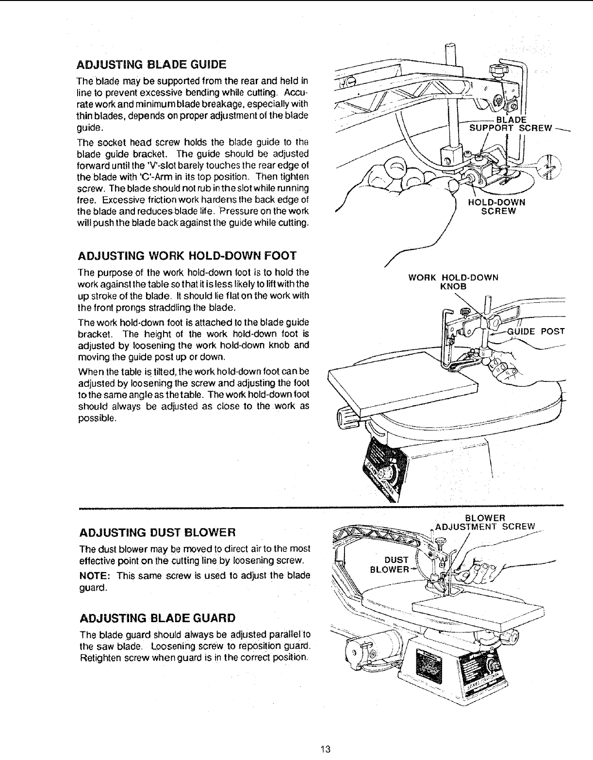
ADJUSTING BLADE GUIDE
The blade may be supported from the rear and held in
line to prevent excessive bending while cutting, Accu-
rate work and minimum blade breakage, especially with
thin blades, depends on proper adjustment of the blade
guide.
The socket head screw holds the blade guide to the
blade guide bracket. The guide should be adjusted
forward until the 'V'-slot barely touches the rear edge oi
the blade with 'C'-Arm in its top position. Then tighten
screw. The blade should not rub inthe slot while run ning
free. Excessive friction work hardens the back edge of
the blade and reduces blade life. Pressure on the work
will push the blade back against the guide while cutting,
ADJUSTING WORK HOLD-DOWN FOOT
The purpose of the work hold-down foot is to hold the
work against the table sothat it is less likelyto liftwith the
up stroke of the blade. It should lie flat on the work with
the front prongs straddling the blade.
The work hold-down foot is attached to the blade guide
bracket. The height of the work hold-down foot is
adjusted by loosening the work hold-down knob and
moving the guide post up or down.
When the table is tilted, the work hold-down foot can be
adjusted by loosening the screw and adjusting the foot
to the same angle as the table. The work hold-down foot
should always be adjusted as close to the work as
possible,
SUPPORT SCREW
HOLD-DOWN
SCREW
WORK HOLD-DOWN
KNOB
iUIDE POST
ADJUSTING DUST BLOWER
The dust blower may be moved to direct air to the most
effective point on the cuttingline by loosening screw.
NOTE: This same screw is used to adjust the blade
guard.
ADJUSTING BLADE GUARD
The blade guard should always be adjusted parallel to
the saw blade, Loosening screw to reposition guard.
Retighten screw when guard is in the correct position.
BLOWER
.ADJUSTMENT SCREW
I3
.assembly and alignment
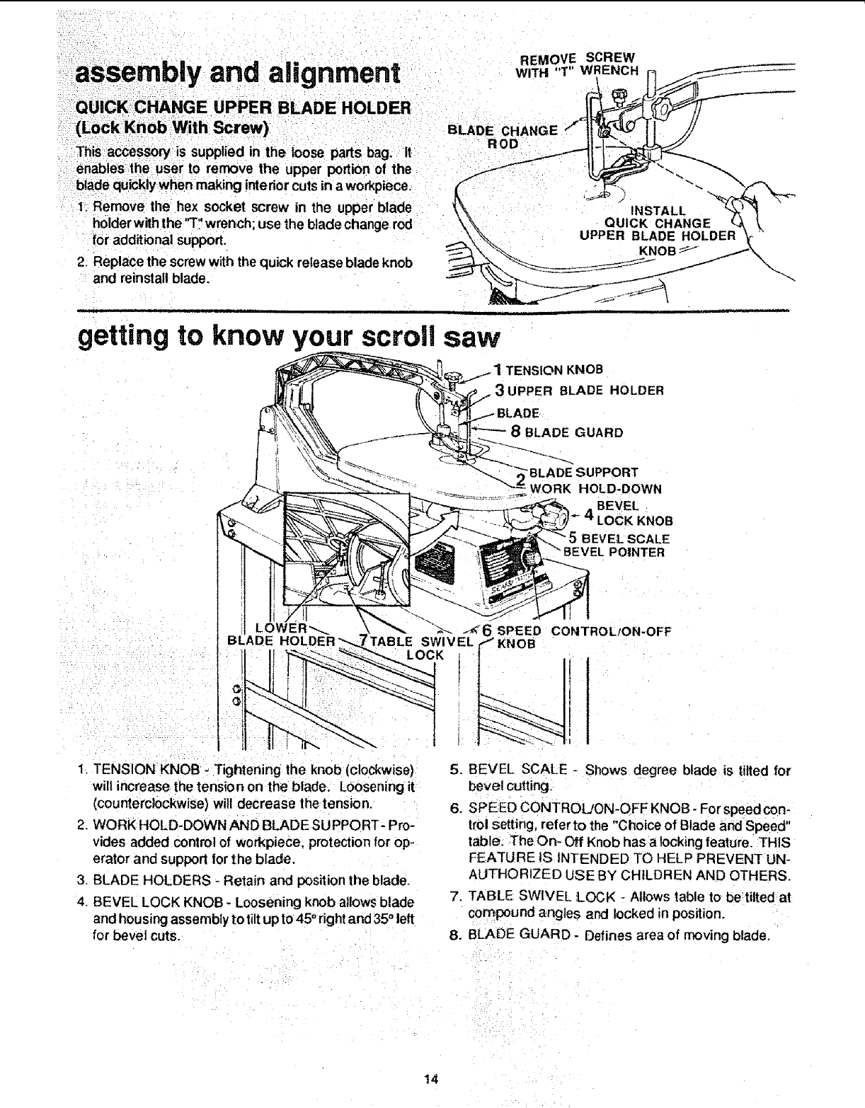
(L0ckKnob With Screw)
This access0ry is supplied in the loose parts bag. it
enables the user to remove the upper portion of the
blade quicklywhen making interiorcuts in aworkpiece.
i.1Remove the hex socket screw in the upper blade
• t!
holder with the "T wrench; use the blade change rod
for additional support,
2_Replace the screw with the quick release blade knob
and reinstall blade.
REMOVE SCREW
WITH "T" WRENCH r_
ROD
INSTALL
QUICK CHANGE
UPPER BLADE HOLDER
KNOB
\-.._
i i i i i
getting to know your scroll saw
1 TENSION KNOB
BLADE HOLDER
GUARD
•BLADESUPPORT
_. WORK HOLD-DOWN
BEVEL
_- 4LOCK KNOB
BEVEL SCALE
POINTER
1. TENSION KNOB - Tightening the knob (clockwise)
will increase the tension on the blade. Loosening it
(counterclockwise) will decrease the tension.
2. WORK HOLD-DOWN AND BLADE SU PPORT- Pro-
vides added control of workpiece, protection for op-
erator and support for the blade.
3. BLADE HOLDERS - Retain and position the blade.
4. BEVEL LOCK KNOB -Loosening knob allows blade
and housing assembly to tilt up to 45 ° right and 35° left
for bevel Cuts.
6SPEED CONTROL/ON-OFF
SWIVEL _ KNOB
LOCK
5. BEVEL SCALE - Shows degree blade is tilted for
bevel cutting.
6. SPEED CONTROL/ON-OFF KNOB- For speedcon-
trol Setting, refer to the "Choice of Blade and Speed"
table. Thegn- Off Knob has a locking feature. THIS
FEATURE 1S INTENDED TO HELP PREVENT UN-
AUTHORIZED USE BY CHILDREN AND OTHERS.
7. TABLE SWIVEL LOCK - Allows table to be tilted at
compound angles and locked in position.
8. BLADE GUARD - Defines area of moving blade.
14
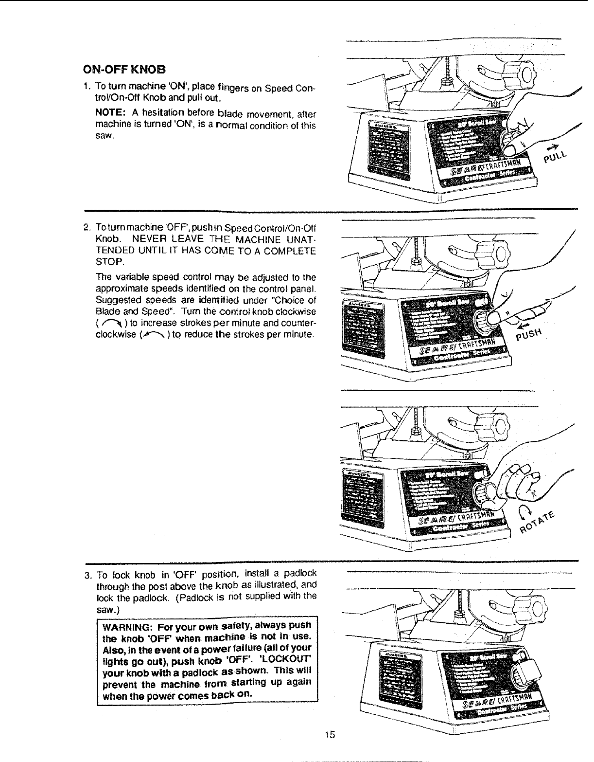
ON-OFF KNOB
1. To turn machine 'ON', place fingers on Speed Con_
trol!On-Off Knob and pull out.
NOTE: A hesitation before blade movement, after
machine is turned 'ON', is a normal condition ol this
saw,
,= i , illll ii
2. Toturnmachine'OFF',pushin SpeedControl/On-Off
Knob. NEVER LEAVE THE MACHINE UNAT-
TENDED UNTIL IT HAS COME TO A COMPLETE
STOP.
The variable speed control may be adjusted to the
approximate speeds identified on the control panel.
Suggested speeds are identified under "Choice of
Blade and Speed". Turn the control knob clockwise
(/"'_ ) to increase strokes per minute and counter-
Clockwise (,_,"_) to reduce the strokes per minute.
H,=H==,H,,,,I =H
3. To lock knob in 'OFF' position, install a padlock
through the post above the knob as illustrated, and
lock the padlock. (Padlock is not supplied with the
saw.)
WARNING: For your own safety, always push
the knob 'OFF' when machine Is not in use.
Also, in the event of a power failure (all of your
lights go out), push knob 'OFF'. 'LOCKOUT'
your knobwitha padlock asshown. This will
prevent the machine from starting up again
when the power comes back on.
m,i ,i i[=[ = =1
15

1: Use afiner tooth blade for cutting thin workpieces,
When asmoother Cut is required, for hard materials, or
when using slower saw speeds.
3. Use: a blade that will have at least 2 teeth in the mate-
rial at all times.
4. Use thin narrow blades for tight radius work, and thick,
wide blades for large curves and straight cuts.
Listed below are examples of some blades and their intended uses:
Teeth/Inch Width
20 _ .029"
15 .110"
12.5
11.5
t0
Thickness Speed Application
'1 ' i i '
.012"
.018"
.038" .016"
.053" .018" 1200-2000
.110" .018"
400-600 Tight radius work;3/32" to 1/8" wood veneer, wood,
bone, fiber, plastics, non-ferrous metals, etc.
600-1200 Close radius cutting in materials 3/32" to 1/2" thick.
Good for hard and soft wood, bone, horn, plastics, etc.
For hard and soft woods and woodlike products 3/t6"
and up.
i i i p ill | .i
basic saw operations
BEFORE EACH USE:
Inspect your saw.
DISCONNECT THE SAW. To avoid injury from acciden-
tal starting, unplug the saw. push the switch "OFF' and
lock the switch before changing the setup or removing
covers, guards or blade.
CHECK DAMAGED PARTS. Check for:
• alignment of moving parts.
': binding of moving parts.
• broken parts:
• stable mounting, and
o any other conditions that may affect the way the saw
WOrkS, :
If any part is missing, bent or broken in any way, or any
electrical part doesn't work properly, turn off and unplug
the saw. REPLACE damaged, missing or failed parts
before using the saw again.
MAINTAIN TOOLS WITH CARE.
Keep the saw clean for the best and safest performance.
Follow instructions for lubricating.
REMOVE ADJUSTING KEYS AND WRENCHES from
too! before turning it on.
To avoid injury from jams, slips or thrown pieces.
- Choose the right size and style blade for the material
and the type of cutting you plan to do.
•USE ONLY RECOMMENDED ACCESSORIES. (See
page 20). Consult this Owner's manual for recom-
mended accessories. Follow the instructions that come
with the accessories. The use ot improper accessories
may cause risk of injury to persons.
•Make sure the blade teeth point downward, toward the
table.
•Make sure the blade tension is properly adjusted.
• Make sure the bevel lock knob is tight and no parts
have excessive play.
• To avoid accidental blade contact, minimize blade
breakage and provide maximum blade support, always
adjust the blade hold-down and blade guard to just
clear the workpiece.
• KEEP WORK AREA CLEAN. Cluttered areas and
benches invite accidents. Floor must not be slippery.
To avoid bums or other fire damage, never use the saw
near flammable liquids, vapors or gases.
PLAN AHEAD TO PROTECT YOUR EYES,
HANDS, FACE, EARS
KNOW YOUR SAW. Read and understand the owners
manual and labels affixed to the tool. Learn its applica-
tions and limitations as well as the specific potential haz-
ards peculiar to this tool.
To avoid injury from accidental contact with moving parts,
don't do layout, assembly or setup work on the saw while
any parts are moving.
16

AVOID ACCIDENTAL STARTING. Make sure switch is
"OFF" before plugging saw into a power outlet.
Plan your work.
• USE THE RIGHT TOOL. Don't force tool or attach-
ment to do a job it was not designed to do.
•Use this scroll saw to cut only wood, wood like
products, plastics and non-ferrous metals.
CAUTION: ThiS saw is N_.O_Tdeslgned for cutting
ferrous metals like iron or steel, When cutting
non-ferrous metals (brass, copper and alumi-
num, etc.), metal shavings can react with wood
dust and start a fire. To avoid this:
. Disconnect any dust collecting hose from the
saw.
• Remove all traces of wood dust from inside the
saw.
•Remove all traces of metal dust from on or
around the saw before sawing wood again.
Dress for safety.
Any power tool can throw foreign objects into the eyes.
This can cause permanent eye damage. Wear safety
goggles (not glasses) that comply with ANSI Z87.1
(shown on package). Everyday eyeglasses have only
impact resistant lenses. They are not safety glasses.
Safety goggles are available at Sears retail catalog
stores. Glasses or goggles not in compliance with ANSI
Z87.1 could seriously hurt you when they break.
• Do not wear loose clothing, gloves, neckties or jew-
elry (rings, wrist watches). They can get caught and
draw you into moving parts.
• Wear nonslip footwear.
• Tie back long hair.
•Roll long sleeves above the elbow.
• Noise levels vary widely: To avoid possible hearing
damage, wear ear plugs or muffs when using saw for
hours at a time.
•For dusty operations, wear adust mask along withthe
safety goggles.
Inspect your workplece
Make sure there are nonails or foreign objects inthe part
of the workpiece to be cut.
Use extra caution with large, very small or awkward
workpieces:
• Never use thistoolto finish piecestoo smalttoholdbY
hand.
•Use extra supports (tables, saw horses, blocks, etc.)
for any workpieces large enough to tip when not held
down to the table top.
• NEVER use another person as a substitute for a table
extension, or as additional support for a workpiece or
to help feed, support or pull the workpiece.
• When cutting irregularly shaped workpieces, plan
your work so it will not pinch the blade. A piece of
molding, for example, must lay flat or be held by a
fixture or iig that will not let it twist, rock or slip while
being cut.
Properly support round material such as dowel rods,
or tubing. They have a tendency to roll during a :cut,
causing the blade to "bite',. To avoid this, always use
a "V" block.
-Cut only one workpiece at a time.
•Clear everything except the workpiece and related
support devices off the table before turning the saw
on.
Plan the way you will hOld the workplece from start
to finish.
Do not hand hold pieces so smalt that your fingers wil_go
underthework hold-down. Use jigs orfixturesto holdthe
work and keep your hands away from the blade.
SECURE WORK. Use clamps to hold work when
practical, lt'soften safer than using your hand, and frees
both hands to operate the tool.
Avoid awkward operations and hand positions where a
sudden slip could cause fingers or hand to move intothe
blade.
DON'TOVERREACH. Keep good footing and batance.
Keep your face and body to one side of blade, out of line
with a possible thrown piece ifthe blade should break..
WHENEVER SAW IS RUNNING
WARNING: Don't Betfamiliarity (gained from fre-
quent use of your saw) cause acareless mistake.
A careless fraction of asecond is enough to
cause a severe injury.
Before starting your cut, watch the saw while it runs. If
it makes an unfamiliar noise or vibrates a for, stop
immediately. Turn the saw off. Unplug the saw. Do not
restart until finding and correcting the problem.
KEEP CHILDREN AWAY. Keep all visitors a safe
distance from the saw. Make sure bystanders are clear
of the saw and workpiece.
DON'T FORCE TOOL. it wilt do the job better and safer
at its designed rate. Feed the workpiece into the saw
blade only fast enough to let it cut without bogging down
or binding.
Before freeing any jammed material:
o Push switch "OFF".
,Lock the switch.
- Unplug the saw.
• Wait for all moving parts to stop.
When backing up the workpiece, the blade may bind
in the kerr (cut). This is usually caused by sawdust
clogging up the kerr. If this happens:
• Push switch "OFF',
-Lock the switch.
17
ii i
.OPERATION OF YOUR SCROLL SAW
PLEASE, read and understand the following items about
your scroll saw before attempting to use the saw.
1. Do notforce workpiece intothe blade, Allowthe saw
to cut the workpiece by .guidingthe wood into the
blade.
2. The blade teeth cut wood ONLYon the down stroke.
3. You must guide the wood into the blade slowly
because the teeth of the blade are very small and
they can only remove wood when they are on the
down stroke.
4. There is a learning curve for each person using this
saw. Dudng that period of time, it is expected that
some blades willbreak untilyoulearn howto use the
saw and receivethe greatest benefitfromthe blades.
5. Best results are achieved when cutting wood less
than one inch thick.
6. When cutting wood thicker than one inch the user
mustguide the wood very, very slowly intothe blade,
and take extra care not to bend or twist the blade
while cutting in order to maximize blade life.
7. Teeth on scroll saw blades wear out and as such
must be replaced frequently for best cutting results.
Scroll saw blades generally stay sharp for 1t2 hour
to 2houm of cutting.
8 To get accuratecuts; be prepared tocompensate for
the tendency of the blade tofollow the wood grain as
you are cutting.
9. This scroll saw is intended to cut wood, wood like
materials, or non-ferrous metal.
i u|
10. When choosing a blade to use with your scroll saw,
consider the following carefully,
•Very fine, narrow blades should be used to scroll
cut in thin wood 1;4 inch thick or less.
•To cut wood over 1t4 inch thick, use wider blades.
•Most blade packages state'the size or thickness
of wood which that blade is intended to cut, and
the minimum radius which can be cut with that
blade.
• Wider blades can't cut curves as tight or small as
thinner blades.
•Narrower blades work well only on thinner wood
material.
11. When selecting the cutting speed, keep the lo Ilow-
ing in mind:
• Slower speeds are generally more effective than
faster speeds, especially when using thin blades
and making intricate cuts.
•To find the best speed, start at a slow speed and
gradually increase the speed until the optimum
cutting rate is achieved.
12.This saw uses 5 inch long, plain end or pin type
blades. See your Sears Catalog or Retail Store for
accessory blades.
13. Blades wear faster when cutting plywood, which is
very abrasive, when sawing wood which is thicker
than the 3/4 inch, and when sawing hardwood, or
when side pressure is placed on the blade.
18
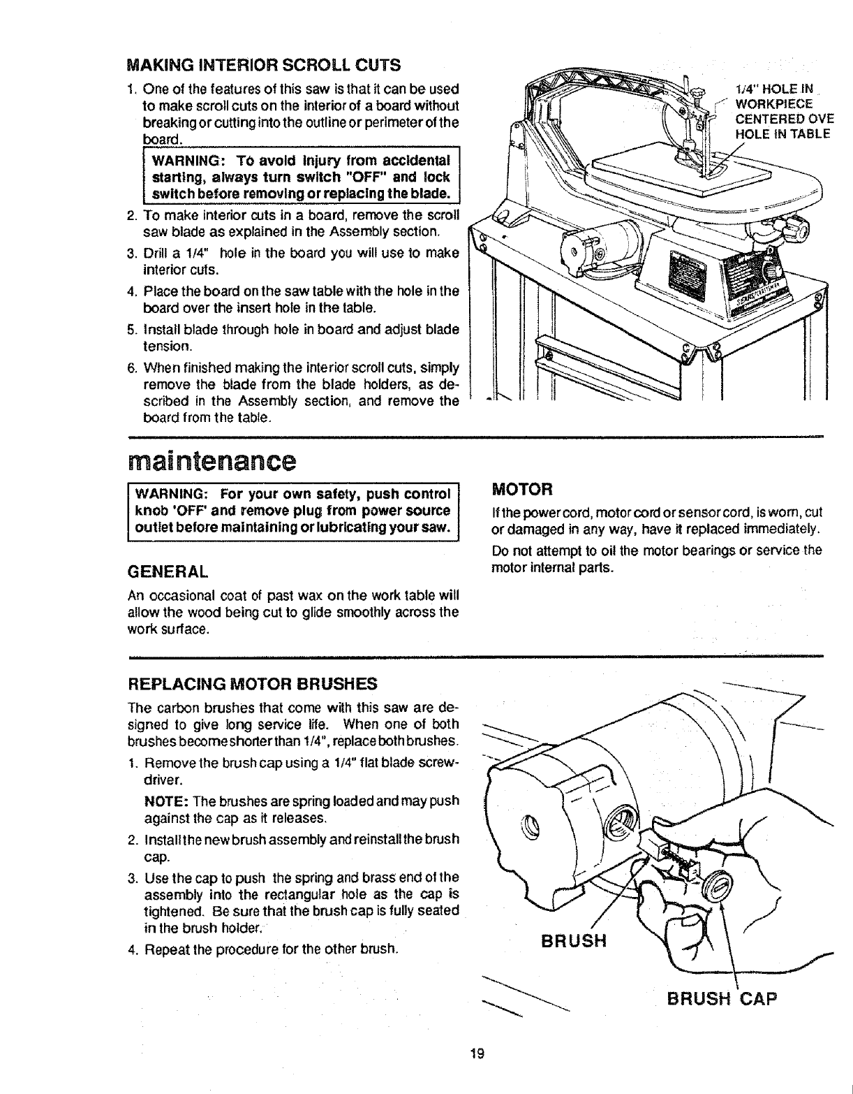
MAKING INTERIOR SCROLL CUTS
1. One of the features of th{ssaw is that it can be used
to make scroll cuts on the interiorof a board without
breaking or cuttinginto the outline or perimeter of the
board.
WARNING: TO avoid injury from accidental
starting, always turn switch "OFF" and lock
switch before removing or replacing the blade.
2. To make interior cuts in a board, remove the scroll
saw blade as explained in the Assembly section.
3. Drill a1/4" hole inthe board you will use to make
interior cuts.
4. Place the board onthe saw table with the hole in the
board over the insert hole in the table.
5. install blade through hole in board and adjust blade
tension.
6. When finished making the interiorscroll cuts, simply
remove the blade from the blade holders, as de-
scribed in the Assembly section, and remove the
board from the table.
1J4" HOLE IN
WORKPIECE
CENTERED OVE
HOLE tN TABLE
maintenance
WARNING: For your own safety, push control
knob 'OFF' and remove plug from power source
outlet before maintaining or lubricating your saw.
GENERAL
An occasional coat of past wax on the work table will
allow the wood being cut to glide smoothly across the
work surface.
MOTOR
If the power cord, motor cord or sensor cord, isworn, cut
or damaged in any way, have it replaced immediately.
Do not attempt to oi! the motor bearings or service the
motor internal parts.
REPLACING MOTOR BRUSHES
The carbon brushes that come with this saw are de*
signed to give long service life. When one of both
brushes becorne shorter than 1/4", replace both brushes.
1. Remove the brush cap using a 1/4" flat blade screw-
driver.
NOTE: The brushes are spring loaded and may push
against the cap as it releases.
2. Installt he new brush assembly and reinstalithe brush
cap.
3. Use the cap to push the spring and brass end of the
assembly into the rectangular hole as the cap is
tightened. Be sure that the brush cap is fully seated
in the brush holder,
4. Repeat the procedure for the other brush. BRUSH
BRUSH CAP
19
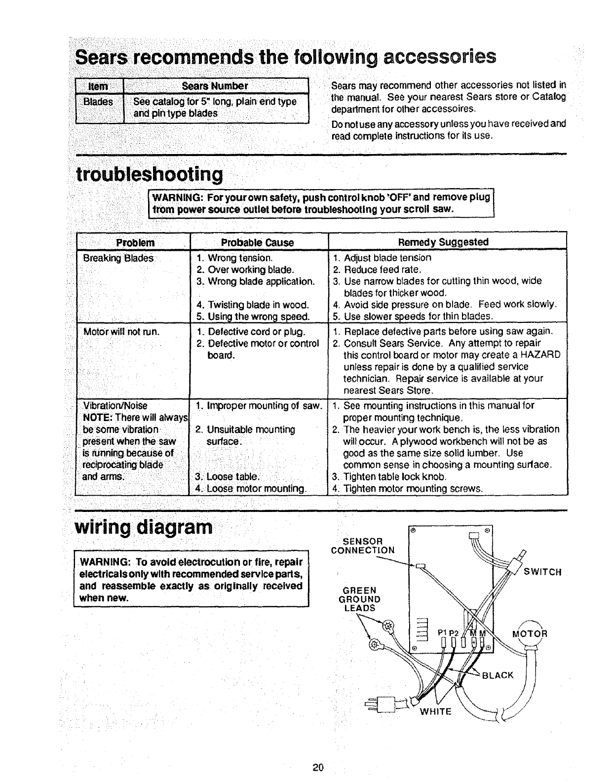
the following accessories
Sears may recommend other accessories not listed in
the manual. See your nearest Sears store or Catalog
department for other accessoires.
Do not use any accessory unless you have received and
read complete instructions for its use.
[ WARNING: For your own safety, push control knob 'OFF' and remove plug I
I from power source outlet before troubleshooting your scroll saw.
Problem
Breaking Blades
E
Motorwitl not run.
L -
i .
Vibrat_n/Noise
Probable Cause
1. Wrong tension.
2. Over working blade.
3. Wrong blade application.
4. Twisting blade in wood.
5, Using the wrong speed.
1. Defective cord or plug.
2. Defective motor or control
board.
Remedy Suggested
1. Adjust blade tension
2. Reduce feed rate.
3. Use narrow blades for cutting thin wood, wide
blades for thicker wood.
4. Avoid side pressure on blade. Feed work slowly.
5. Use slower speeds for thin blades.
1. Replace defective parts before using saw again.
2. Consult Sears Service. Any attempt to repair
this control board or motor may create a HAZARD
unless repair is done by a qualified service
technician. Repair service is available at your
nearest Sears Store.
t. Improper mounting of saw. "t. See mounting instructions in this manual for
NOTE: There wJl!always prope r mounting technique.
be some v_ration 2. Unsuitable mounting
present when thesaw surface,
is running because of l
reciprocatingblade I:
and arms, 3. Loose table.
:4. Loose motor mounting.
2. The heavier your work bench is, the less vibration
will occur. A plywood workbench wilt not be as
good as the same size solid lumber. Use
common sense in choosing a mounting surface.
3. Tighten table lock knob.
4. Tighten motor mounting screws.
wiring diagram
WARNING: To avoid electrocution or fire, repair
electrtcals only with recommended service parts,
and reassemble exactly as originally received
when new.
SENSOR
CONNECTION
GREEN
GROUND
LEADS
MOTOR
WHITE
2O
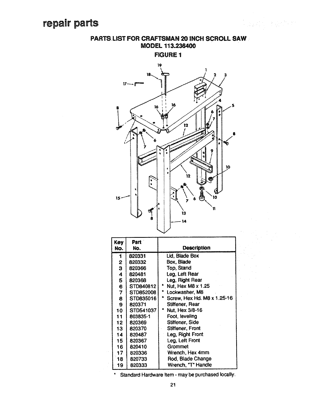
repair parts
PARTSUST FOR CRAFTSMAN 20 INCH SCROLL SAW
MODEL 113.236490
FIGURE 1
19 12 3
813
\11
Key
NO.
1
2
3
4
5
6
7
8
9
10
11
12
13
14
15
16
17
18
19
Part
No. Description
ii i i u i II,HI,
820331 Lid, Blade Box
820332
820366
820481
820368
STD840812 *
STD852008 *
STD835016 *
820371
STD54t037 *
803835-1
820369
820370
820487
820367
820410
820336
820733
820333
Box, Blade
Top, Stand
Leg, Left Rear
Leg, Right Rear
Nut, Hex M8 x 1.25
Lockwasher, M8
Screw, Hex Hd. M8 x 1.25-t6
Stiffener, Rear
Nut, Hex 3/8-16
Foot, leveling
Stiffener, Side
Stiffener, Front
Leg, Right Front
Leg, Left Front
Grommet
Wrench, Hex 4ram
Rod, Blade Change
Wrench, THandle
Standard Hardware Item - may be purchased locally,
21
54
\
2
51
52
pARdi LIST FOR CRA_MAN 20 INCH SCROLL SAW
:_: _:: iMODEL 11
6
s
I
k
53
\
/
16
Figure 2
2O
22
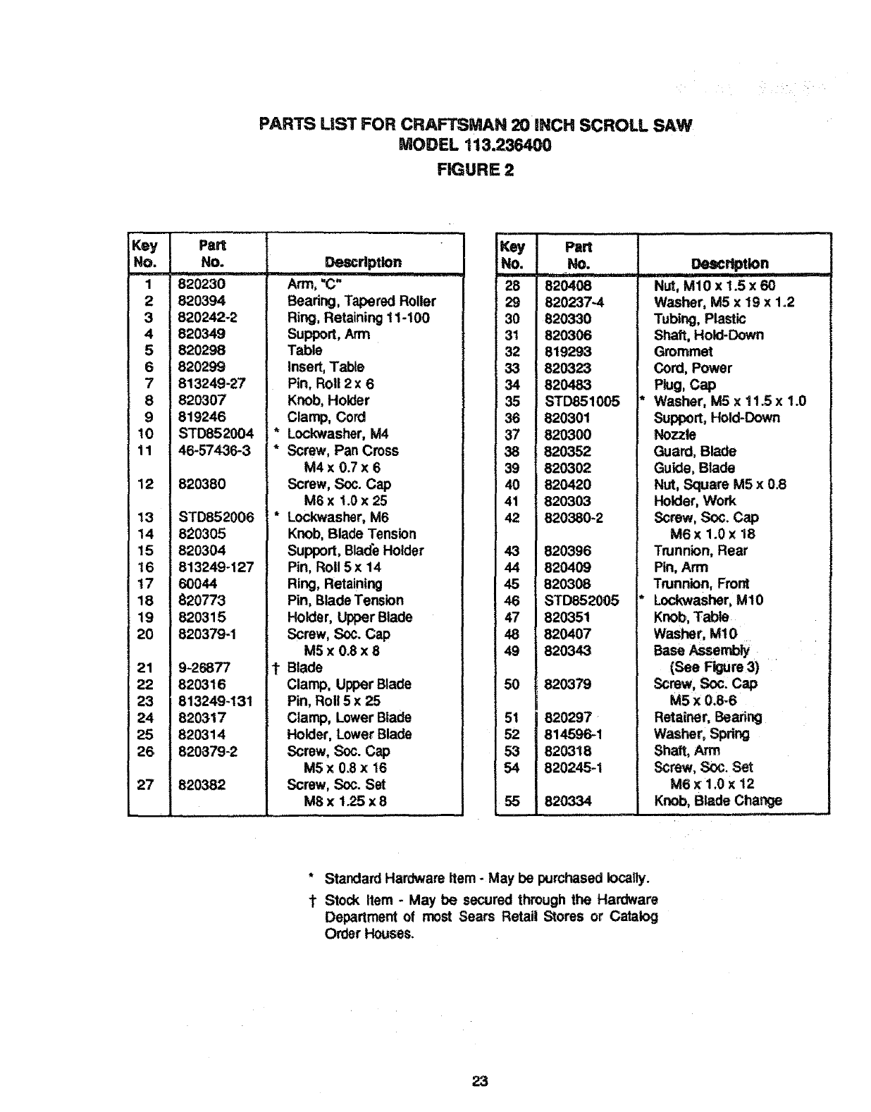
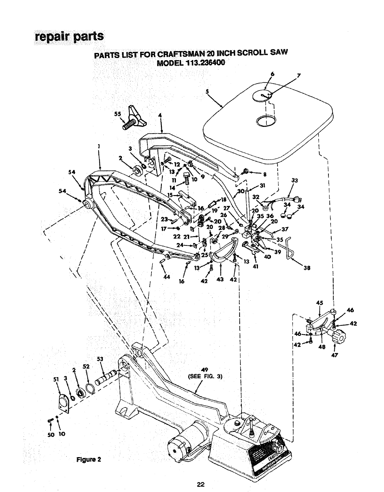
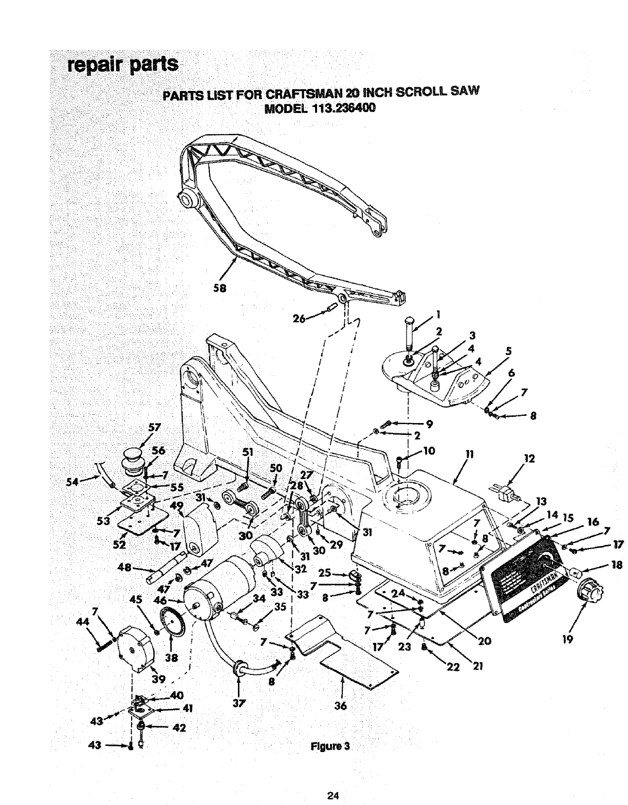
PARTS LiST FOR CRAFTSMAN 20 iNCH SCROLL SAW
MODEL 113.236400
FIGURE 2
Key
NO,
1
2
3
4
5
6
7
8
9
10
11
12
13
14
15
16
17
18
19
20
21
22
23
24
25
26
27
Part
No.
820230
820394
820242-2
820349
820298
820299
813249-27
820307
819246
STD852004
46-57436-3
820380
STD852006
820305
820304
813249-127
6O044
820773
820315
820379-1
9-26877
820316
813249-131
820317
820314
820379-2
820382
Description
Arm, "C"
Bearing, Tapered Roller
Ring, Retaining 11-100
Support, Arm
Table
Insert, Table
Pin, Roll 2 x 6
Knob, Holder
Clamp, Cord
* Lockwasher, M4
* Screw, Pan Cross
M4 x 0.7x 6
Screw, Soc. Cap
M6 x t.0 x 25
* Lockwasher, M6
Knob, Blade Tension
Support, Blade Holder
Pin, Roll 5 x 14
Ring, Retaining
Pin, Blade Tension
Holder, Upper Blade
Screw, Soc. Cap
M5x 0.8x8
1" Blade
Clamp, Upper Blade
Pin, Roll 5 x 25
Clamp, Lower Blade
Holder, Lower Blade
Screw, Soc. Cap
MSx O.8x 16
Screw, Soc. Set
MBx 1.25 x 8
No.
i
28
29
30
31
32
33
34
35
36
37
38
39
40
41
42
43
44
45
46
47
48
49
5O
51
2
53
54
55
Part
No.............
820237-4
820330
82O306
819293
820323
820483
STD851005 *
820301
820300
820352
820302
820420
820303
820380-2
820396
820409
820308
STD852005 *
Description
iiiiiiiif
Nut, M10 x 1.5 x 60
Washer, M5 x 19 x 1.2
Tubing, Plastic
Shaft, Hold-Down
Grommet
Cord, Power
PkJg,cap
Washer, M5 x 11.5 x 1.0
Support, Hold-Down
Nozzle
Guard, Blade
Guide, Blade
Nut, Square M5 x 0.8
Holder, Work
Screw, _x_. Cap
M6 x 1.0 x 18
Trunnion, Rear
Pin, Arm
Trunnion, Front
Lockwasher, M10
820351
820407
820343
820379
820297
814596-1
820318
820245-1
820334
Knob, Table
Washer, MIO
Base sem y
(See Figure 3)
Screw,Soc.Cap
M5 x 0.6-6
Retainer, Bearing
Washer, Spring
Shaft, Arm
Screw, Soc. Set
M6 x 1.0 x 12
Knob, Blade Change ,,,, J
* Standard Hardware Item - May be purchased iocatly.
1" Stock Item -May be secured through the Hardware
Department of most Sears Retai! Stores or Catalog
Order Houses.
23
120 INCH SCROLL SAW
MODEL 113,236400
57
58
/
/
!
!
/
45
44
36
Flgum 3
31
23 &
13
15 16
18
24

PARTS LiST FOR CRAFTSMAN 20 iNCH SCROLL SAW
MODEL 113.236400
FIGURE 3
Key! Pa.
No ,1........No.,............
! 820405
2 STD852006
3 STD835080
4 STD840812
5 820395
6 820309
7 STD852004
8 46-57529-3
9 820249-3
10 820380-2
11 820343
12 820774
13 820240-1
14 STD852005
15 820363
16 820362
17 46-57436-3
18 820335
!9 820365
20 820361
21 820329
22 836743-1
23 820422
24 STD840407
25 820482
26 820409
27 820495
28 820495-1
29 820245-1
30 820603
31 820397-1
.... Descr!ptlon
!l !
Bott, Hex M10 x 1.5 x 60
* Lockwasher, M6
"Screw, Hex M8 x1.25 x 80
*Nut, Hex M8 x 1.25
Support, Table
Pointer, Bevel
* Lockwasher, M4
* Screw, Pan Cross M4 x.0.7 x
Screw, Hex M6 x 1.0 x 25
Screw, Soc. Cap M6 x t .0 x 18
Base
Switch
Screw, Pan Cr. M5 x 0.8 x 10
* Lockwasher, M5
Gasket, Foam
Cover, Front
* Screw, Pan Cr. M4 x 0.7 x 8
Post, Lock
Knob, Control
Board, Control
Cover, Electronics
Screw, Pan Cr. M4 x 0.7 x 20
Spacer, 4.5 x 8 x 14
* Nut, Hex M4 x 0.7
Clamp, Cord
Pin, Arm
(Reference, See Fig. 2)
Spacer, Nylon 8 x 12 x I
Spacer, Nylon 8 x 12 x 4
Screw, Soc. Set M6x 1.0 x 12
Link w/Bearings
Spacer, 8 x 12 x 4
Key Pa_ .........]
No. No.
i iii
32 820358
33 820245-2
34 820322
35 820324
36 820428
37 819293
38 820327
39 820325
40 820602
41 820357
42 169123-8
43 820401
44 46-57509-3
45 STD840610
46 820353
47 805641-9
48 820360
49 820604
50 820239-2
51 820239-1
52 820344
53 820345
54 820330
55 820347
56 46-57477-3
57 820346
58 820230
-- SP5498
,Descrlp,tlon-
Counterbalance, Vertical
Screw, Soc. Set M6 x 1.0 x 8
Brush and Spring
Cap, Brush
Cover, Drive
Grommet
Disc, Encoder
Cover, Encoder
Board, Encoder
Cover, Cord
Relief, Strain
Screw, Pan Hd. M3 x 0.5-6
* Screw, Pan Hd M4 x 0.7-25
Nut, M6 x 1.0
Motor, Complete
Ring, Retaining 11-420
Shaft, Counterbalance
Counterbalance, w/Bearings
Screw, Soc, Cap
M8 x 1.25 x 30
Screw, Soc. Cap
M8 x 1.25 x 20
Mount, Pump
Housing, Pump
Tubing, Plastic
(Reference, See Fig. 2)
Retainer, Boot
* Screw, Pan Cr. M4 x 0.7 x 12
Boot, Pump
Arm, "C"
(Reference, See Fig. 2)
Owner's Manual (Not lttus.)
Standard Hardware Item - May be purchased locally.
25

MODEL NO.
113.236400
SCROLL SAW
Variable Speed
With Stand
The modei number of your
Scroll Saw will be found
attached at the rear of saw.
When requesting service or
ordering parts, always provide
the following info rmation:
•Product Type
-Model Number
•Part Number
•Part Description
Part No. SP5498
CONTRACTOR SERmES
20" VARIABLE SPEED
SCROLL SAW
For the repair orreplacement parts you need
Call 7am - 7pro, 7 days a week
1-800-366-PART
(1-800-368-7278)
For in-homemajor brandrepair service
Col{ 24 hours a day, 7 days a week
1-800-4-RIEPAIR
(1-800-473-7247)
For the location of a
Sears Repair Service Center in your area
OalJ24 hours a day, 7 days a week
1-800-488-1222 ===If=
For information onpurchasinga Sears
Maintenance Agreementor to inquire
about an existing Agreement
Calf 9 am -5 pro, Monday-Saturday
1-800-827-6655
SEARS
America's Repair Sp_tists
Sears Roebuck and Co., Hoffman Estates, IL. 60179 U.S.A.
Form No, SP5498-3 Printed in Taiwan I0/96
