Craftsman 113248210 User Manual BAND SAW Manuals And Guides L0803605
CRAFTSMAN Saw Band Manual L0803605 CRAFTSMAN Saw Band Owner's Manual, CRAFTSMAN Saw Band installation guides
113248510 ba6b9168-d9dc-4824-8b10-7e8de685d7ba Craftsman Saw 113.248510 User Guide |
User Manual: Craftsman 113248210 113248210 CRAFTSMAN BAND SAW - Manuals and Guides View the owners manual for your CRAFTSMAN BAND SAW #113248210. Home:Tool Parts:Craftsman Parts:Craftsman BAND SAW Manual
Open the PDF directly: View PDF ![]() .
.
Page Count: 52
rIlll
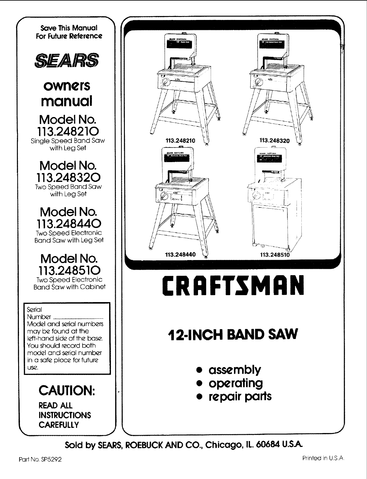
Save ThisManual
ForFuture Reference
S _AIRS
owners
manual
Model No.
113.248210
Single Speed Band Saw
with Leg Set
Model No.
113.248320
Two Speed Band Saw
with Leg Set
Model No.
113.248440
Two Speed Electronic
Band Saw with Leg Set
Model No.
113.248510
Two Speed Electronic
Band Saw with Cabinet
S_rial
Number .
Model and s_rial numbers
may b_ found at the
left-hand side of the bas_.
You should record both
model and s_rial number
in a safe place for futur_
US_.
CAUTION:
READALL
INSTRUCTIONS
CAREFULLY
113.248440
113.248320
J
113.248510
CRRFTSMRN
12-INCH BAND SAW
• assembly
• operating
•repairparts
Sold by SEARS,ROEBUCKAND CO., Chicago, IL.60684 U.S.A.
J
Part No. SP5292 Printed in U.S,A
FULL ONE YEAR WARRANTY ON CRAFTSMAN BAND SAW
If within one year from the date of purchase, this Craftsman Band Saw tails due to adefect in material or workmanship,
Sears will repair it, free of charge.
WARRANTY SERVICE IS AVAILABLE BY SIMPLY CONTACTING THE NEAREST BEARS SERVICE
CENTER/DEPARTMENT THROUGHOUT THE UNITED STATES.
This warranty applies only while this product is used in the Unltad States.
This warranty gives you specific legal rights and you may also have other rights which vary from state to state.
SEARS, ROEBUCK AND CO., DEPT. 698/731A Sears Tower, Chicago, IL 60684
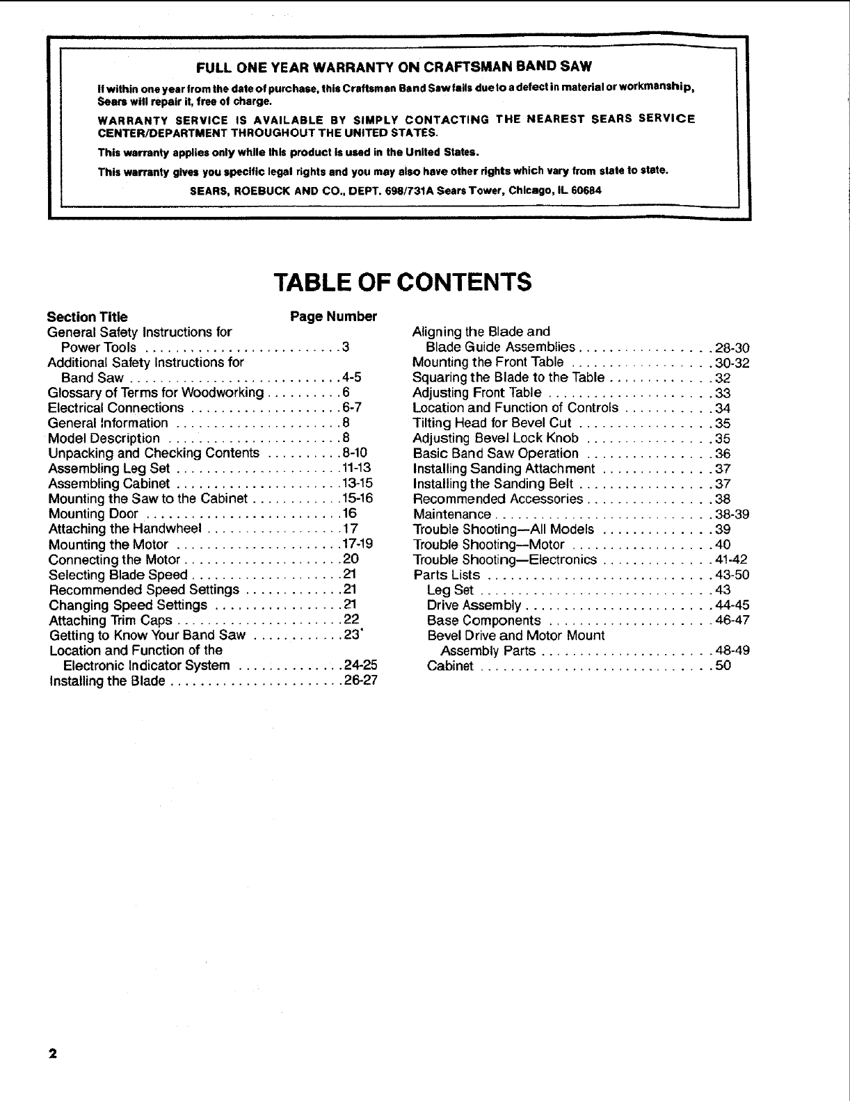
TABLE OF CONTENTS
Section Title Page Number
General Safety Instructions for
Power Tools .......................... 3
Additional Safety Instructions for
Band Saw ............................ 4-5
Glossary of Terms for Woodworking .......... 6
Electrical Connections .................... 6-7
General Information ...................... 8
Model Description ....................... 8
Unpacking and Checking Contents .......... 8-10
Assembling Leg Set ...................... 11-13
Assembling Cabinet ...................... 13-15
Mounting the Saw to the Cabinet ............ 15-16
Mounting Door .......................... 16
Attaching the Handwheel .................. 17
Mounting the Motor ...................... 17-19
Connecting the Motor ..................... 20
Selecting Blade Speed .................... 21
Recommended Speed Settings ............. 21
Changing Speed Settings ................. 21
Attaching Trim Caps ...................... 22
Getting to Know Your Band Saw ............ 23'
Location and Function of the
Electronic Indicator System .............. 24-25
Installingthe Blade ....................... 26-27
Aligning the Blade and
Blade Guide Assemblies ................. 28-30
Mounting the Front Table .................. 30-32
Squaring the Blade to the Table ............. 32
Adjusting Front Table ..................... 33
Location and Function of Controls ........... 34
Tilting Head for Bevel Cut ................. 35
Adjusting Bevel Lock Knob ................ 35
Basic Band Saw Operation ................ 36
Installing Sanding Attachment .............. 37
Installing the Sanding Belt ................. 37
Recommended Accessories ................ 38
Maintenance ............................ 38-39
Trouble Shooting--All Models .............. 39
Trouble Shooting--Motor .................. 40
Trouble Shooting--Electronics .............. 41-42
Parts Lists ............................. 43-50
Leg Set .............................. 43
Drive Assembly ........................ 44-45
Base Components ..................... 46-47
Bevel Drive and Motor Mount
Assembly Parts ...................... 48-49
Cabinet .............................. 50

GENERAL SAFETY INSTRUCTIONS FOR POWER TOOLS
ALL MODELS
1. KNOW YOUR POWER TOOL
Read and understand the owner's manual and
labels affixed to the tool. Learn its application
and limitations as well as the specific potential
hazards peculiar to this tool.
2. GROUND ALL TOOLS
This tool is equipped with an approved
3-conductor cord and a 3-prong grounding type
plug to fit the proper grounding type receptacle.
The green conductor in the cord isthe groundi ng
wire. Never connect the green wire to a live
terminal.
3. KEEP GUARDS IN PLACE,
in working order, and in proper adjustment and
alignment.
4. REMOVE ADJUSTING KEYS AND WRENCHES
Form habit of checking to see that keys and
adj usti ng wrenches are removed from tool before
turning it on.
5. KEEP WORK AREA CLEAN
Cluttered areas and benches invite accidents.
Floor must not be slippery due to wax or sawdust.
6. AVOID DANGEROUS ENVIRONMENT
Don't use power tools indamp orwet locations or
expose them to rain. Keep work area well lighted.
Provide adequate surrounding work space.
7. KEEP CHILDREN AWAY
All visitors should be kept a safe distance from
work area.
8. MAKE WORKSHOP CHILD-PROOF
-- with padlocks, master switches, or by removing
starter keys.
9. DON'T FORCE TOOL
It will do the job better and safer at the rate for
which it was designed.
10. USE RIGHT TOOL
Don't force tool or attachment to do a job it was
not designed for.
11. WEAR PROPER APPAREL
Do not wear loose clothing, gloves, neckties or
jewelry (rings, wrist watches) to get caught in
moving parts. Nonslip footwear is recommended.
Wear protective hair covering to contain long
hair. Roll long sleeves above the elbow.
12. USE SAFETY GOGGLES (Head Protection)
Wear Safety goggles (must comply with ANSI
Z87.1) at all times. Everyday eyeglasses only
have impact resistant lenses, they are NOT
safety glasses. Also, use face or dust mask if
cutting operation is dusty, and ear protectors
(plugs or muffs) during extended periods of
operation.
13. SECURE WORK
Use clamps or a vise to hold work when practical.
It's safer than using your hand, and frees both
hands to operate tool.
14. DON'T OVERREACH
Keep proper footing and balance at all times.
15. MAINTAIN TOOLS WITH CARE
Keep tools sharp and clean for best and safest
performances. Follow instructions for lubricating
and changing accessories.
16. DISCONNECT TOOLS
before servicing; when changing accessories
such as blades, bits, cutters, etc.
17. AVOID ACCIDENTAL STARTING
Make sure switch is in "OFF" position before
plugging in.
18. USE RECOMMENDED ACCESSORIES
Consult the owner's manual for recommended
accessories. Follow the instructions that accom-
pany the accessories. The use of improper acces-
sories-may cause hazards.
19. NEVER STAND ON TOOL
Serious injury could occur if the tool is tipped or
if the cutting tool is accidentally contacted. Do
not store materials above or near the tool such
that it is necessary to stand on the tool to reach
them.
20. CHECK DAMAGED PARTS
Before further use of the tool, a guard or other
part that is damaged should be carefully checked
to ensure that it will operate properly and perform
its intended function. Check for alignment of
moving parts, binding of moving parts, breakage
of parts, mounting, and any other conditions that
may effect its operation. A guard or other part
that is damaged should be properly repaired or
replaced.
21. NEVER LEAVE TOOL RUNNING UNATTENDED
Turn power off. Don't leave tool until it comes to
a complete stop.
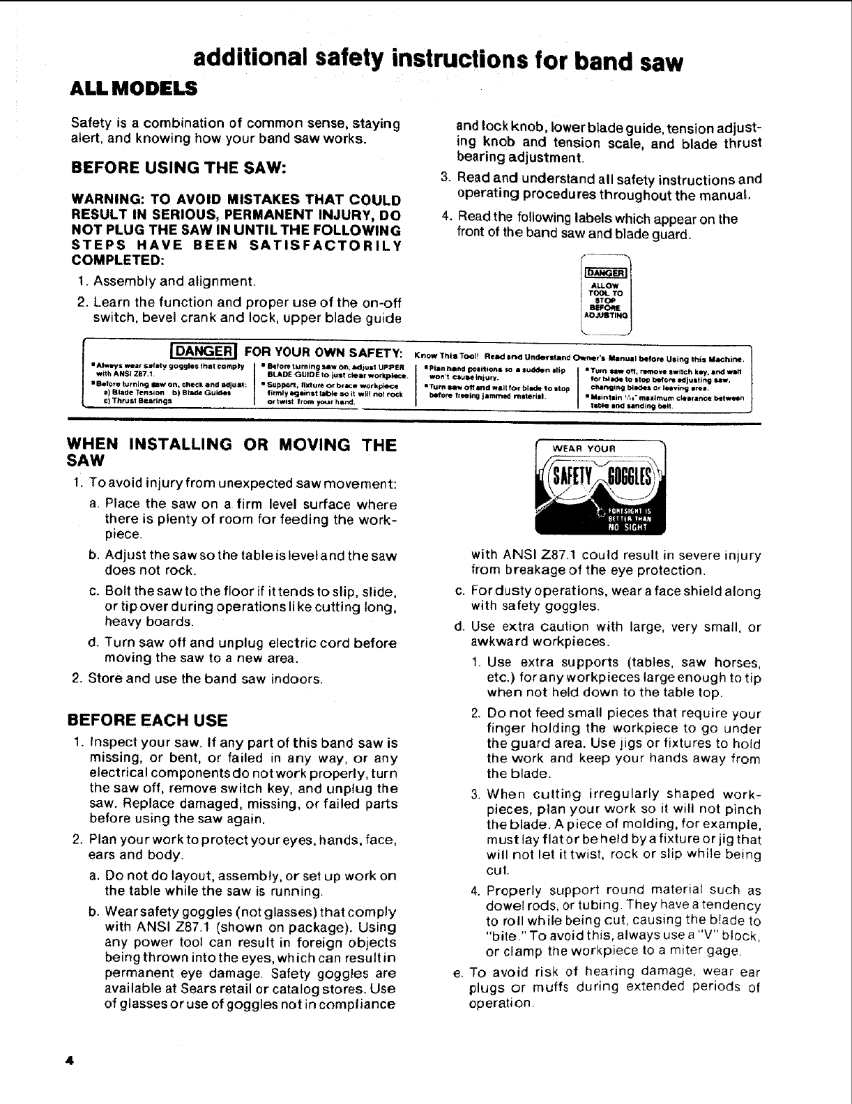
additional safety instructions for band saw
ALL MODELS
Safety is acombination of common sense, staying
alert, and knowing how your band saw works.
BEFORE USING THE SAW:
WARNING: TO AVOID MISTAKES THAT COULD
RESULT IN SERIOUS, PERMANENT INJURY, DO
NOT PLUG THE SAW IN UNTIL THE FOLLOWING
STEPS HAVE BEEN SATISFACTORILY
COMPLETED:
1. Assembly and alignment.
2. Learn the function and proper use of the on-off
switch, bevel crank and lock, upper blade guide
IDANGER I FOR YOUR OWN SAFETY:
• Always wear sM_ty goggles that comply • Before turning saw on, a_lj ust UPPER
with ANSI Z87.t BLADE GUIDE to ius! ciell workptece÷
• Before turning law on, check and adju st: •Supp_, fixture or braK;e workpJe_e
a) Blade Tensic)n b) Blade Guides firmly _mnst tabht so it will not rock
c) Thrust Searingl or twist Irom y_r hand,
and lock knob, lower blade guide, tension adjust-
ing knob and tension scale, and blade thrust
bearing adjustment.
3. Read and understand all safety instructions and
operating procedures throughout the manual.
4. Read the following labels which appear on the
front of the band saw and blade guard.
f----
L___J
Krlow This Tool! Read ind Undersland Owner's Manual before Using this MaChine.
•Plan hand politt _0ns so • sudden •lip • Tt.n _Off. fro'hove switch key, •rid wMt
won't cau_ injury, tot" _4a4e to s|o_ b.efom adjusting _w.
•Turn sew O11 and wa_t for blade to stop char_ltrsg bla<_s or leevir_g arel.
b4r/0fe treeing jammed rnaterlal_ • Meintain _/*1"ma=lmum cl4arance betmn
fiM.e and sanding belt.
WHEN INSTALLING OR MOVING THE
SAW
1. To avoid injury from unexpected saw movement:
a. Place the saw on afirm level surface where
there is plenty of room for feeding the work-
piece.
b. Adjust the saw so the table is level and the saw
does not rock.
c. Bolt the saw to the floor if it tends to slip, slide,
or tip over during operations like cutting long,
heavy boards.
d. Turn saw off and unplug electric cord before
moving the saw to a new area.
2. Store and use the band saw indoors.
BEFORE EACH USE
1. Inspect your saw. If any part of this band saw is
missing, or bent, or failed in any way, or any
electrical componentsdo not work properly, turn
the saw off, remove switch key, and unplug the
saw. Replace damaged, missing, or failed parts
before using the saw again.
2. Plan your work to protect your eyes, hands, face,
ears and body.
a. Do not do layout, assembly, or set up work on
the table while the saw is running.
b. Wear safety goggles (not glasses) that comply
with ANSI Z87.1 (shown on package). Using
any power tool can result in foreign objects
being thrown into the eyes, which can result in
permanent eye damage. Safety goggles are
available at Sears retail or catalog stores. Use
of glasses or use of goggles not in compliance
WEAR YOUR
with ANSI Z87.1 could result in severe injury
from breakage of the eye protection.
c. For dusty operations, wear a face shield along
with safety goggles.
d. Use extra caution with large, very small, or
awkward workpieces.
1. Use extra supports (tables, saw horses,
etc.) forany workpieces large enough to tip
when not held down to the table top.
2. Do not feed small pieces that require your
finger holding the workpiece to go under
the guard area. Use jigs or fixtures to hold
the work and keep your hands away from
the blade.
.When cutting irregularly shaped work-
pieces, plan your work so it will not pinch
the blade. A piece of molding, for example,
must lay flat or be held by a fixtu re or jig that
will not let it twist, rock or slip while being
cut.
4. Properly support round material such as
dowel rods, or tubing. They have a tendency
to roll while being cut, causing the b!ade to
"bite." To avoid this, always use a "V" block,
or clamp the workpiece to a miter gage.
e. To avoid risk of hearing damage, wear ear
plugs or muffs during extended periods of
operation.
Toavoidbeingsuddenlycaughtintheblade:
1.Donotwear gloves.
2. Remove all jewelry and loose clothing.
3. Tie back long hair.
4. Roll long sleeves above the elbow.
g.
h,
j.
k.
To avoid injury from accidental starting, always
unplug saw, turn switch off and remove switch
key before removing the guard, installing or
removing any blade, accessory or attach ment,
or making any adjustments.
To avoid slips and jams causing injury:
1. Choose the right size and style blade for the
material and the type of cutting you plan to
do. Use this band saw to cut and sand only
wood, wood like products and plastic.
2. Make sure the blade teeth point downward
toward the table.
3. Make sure the blade tracking guides and
thrust bearings are properly adjusted.
4. Always check and correctly adjust blade or
sanding belt tension.
To avoid accidental blade contact, minimize
blade breakage and provide maximum blade
support.
1. Always adjust the upper blade guide and
blade guard to just clear the workpiece.
2. Plan your hand placement so your fingers
will not be where a sudden slip could cause
them to hit the blade.
Make sure all clamps and locks are tight and
there is no excessive play in any parts.
To avoid an electrical shock, make sure your
fingers do not touch the metal prongs on the
plug when installing or removing the plug to or
from a live outlet.
Never turn your band saw "ON" before clearing
everything except the workpiece and related
feed or support devices off the table,
BEFORE SANDING
1. Keep the table and sanding belt adjusted so the
gap between them is no more than 1/16-inch
wide.
2. To avoid fire, shock, or cause electrical shorts,
do not sand metal. It could ignite the sawdust
inside the saw.
WHENEVER SAW IS RUNNING
WARNING: DO NOT ALLOW FAMILIARITY
(GAINED FROM FREQUENT USE OF YOUR
BAND SAW) TO CAUSE A CARELESS MIS-
TAKE. ALWAYS REMEMBER THAT A CARE-
LESS FRACTION OF A SECOND IS SUFFI-
CIENT TO INFLICT SEVERE INJURY.
a. If your saw makes an unfamiliar noise or if it
vibrates excessively, stop immediately. Turn
the saw off. Remove switch key and unplug
the saw. Do not restart until finding and
correcting the problem.
b. Avoid awkward hand positions where a sudden
slip could cause a hand to move into the blade
or the sanding belt.
c, Feed the workpiece only fast enough to let the
blade cut without bogging down or binding.
d. Before freeing jammed material, turn saw off.
Remove switch key. Remove plug from power
source outlet. Wait for all moving parts to stop.
e. When backing up the workpiece, the blade
may bind in the kerf (cut). This Js usually
caused by sawdust clogging up the kerr or
because the blade comes out of the guides. If
this happens:
1, Turn saw off.
2. Unplug saw.
3. Remove switch key.
4, Wait for all moving parts to stop.
5. Remove band saw cover.
6. Stick a flat blade screwdriver or wedge into
the kerf.
7. Turn the upper wheel by hand while backing
up the workpiece.
Before removing loose pieces from the table,
turn saw off and wait for all moving parts to
stop.
ACCESSORIES
USE ONLY RECOMMENDED ACCESSORIES. Follow
the instructions that come with the accessories. Con-
sult the owner's manual for recommended accessories.
The use of improper accessories may cause risk of
injury to persons.

glossary of terms for woodworking
ALL MODELS
Beveling
An angle cutting operation through the face of the
board,
Crosscut
A cutting operation made across the width of the
workpiece.
Compound Cutting
A simultaneous bevel and miter cutting operation.
FPM
Feet per minute. Used in reference to surface speed
of blade.
Freehand (as used for band saw)
Performing acut without the workpiece properly
supported on the work table.
Gum
A sticky, sap based residue from wood products.
Kerr
The material removed by the blade in a through cut
or the slot produced by the blade in a non-through or
partial cut.
Leading End
The end of the workpiece which is pushed into the
cutting tool first.
Mitering
An angle cutting operation made across the width of
the workpiece.
Push Stick
A device used to feed the workpiece through the saw
during narrow ripping type operations so the opera-
tor's hands are kept well away from the blade.
Resaw
A cutting operation to reduce the thickness of the
workpiece to make thinner pieces.
Resin
A sticky, sap based substance that has dried.
Ripping
A cutting operation along the length of the work-
piece.
Sawblade Path
The area of the worktable or workpiece directly in
line with the saw blade.
Set
The distance the tip of the saw blade tooth is bent
outward from the face of the blade,
Trailing End
The workpiece end last cut by the saw blade.
Workpiece
The item on which the cutting operation is being
performed. The surfaces of a workpiece are commonly
referred to as faces, ends, and edges.
Worktable
The surface on which the workpiece rests while
performing a cutting or sanding operation.
ALL MODELS electrical connections
POWER SUPPLY
Motor Specifications
The A-C motor used in this saw is a capacitor-start,
non-reversible type having the following specifica-
tions:
24821
1/2
1
120
7.9
60
Single
1725
Clock-
wise
24832
24844
24851
Rated H.P. ...................... 5/8...
Maximum Developed H.R .......... 11/8..
Voltage ......................... 120..
Amperes ....................... 7.9,.
Hertz (Cycles) ................... 60...
Phaze ......................... Single
RPM ........................... 1725.
Rotation of Shaft ................. Clock-
wise
WARNING: TO AVOID ELECTRICAL HAZARDS,
FIRE HAZARDS, OR DAMAGE TO THE TOOL, USE
PROPER CIRCUIT PROTECTION. YOUR SAW IS
WIRED AT THE FACTORY FOR 120V OPERATION.
CONNECT TO A120V, 15-AMP, BRANCH CIRCUIT
AND USE A 15-AMP FUSE OR CIRCUIT BREAKER.
TO AVOID SHOCK OR FIRE, IF POWER C )RD IS
WORN OR CUT, OR DAMAGED IN ANY WAY,
HAVE IT REPLACED IMMEDIATELY.
IF NOT PROPERLY GROUNDED THIS POWER
TOOL CAN CAUSE ELECTRICAL SHOCK --
PARTICULARLY WHEN USED IN DAMP LOCA-
TIONS CLOSE TO PLUMBING. IF AN ELECTRICAL
SHOCK OCCURS THERE IS ALSO THE POTEN-
TIAL OF A SECONDARY HAZARD SUCH AS YOUR
HANDS CONTACTING THE SAWBLADE. NOT ALL
OUTLETS ARE PROPERLY GROUNDED. IF YOU
ARE NOT SURE THAT YOUR OUTLET IS PRO-
PERLY GROUNDED, HAVE IT CHECKED BY A
QUALIFIED ELECTRICIAN.
Your unit has a plug that looks like the one shown
below.
3-PRONG PLUG
PROPERLY _-_i /
GROUNDED
OUTLET
GROUNDING PRONG
e
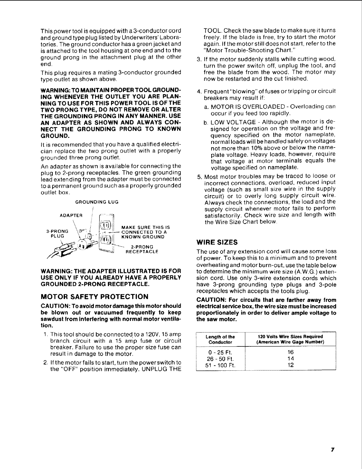
This power tool is equipped with a 3-conductor cord
and ground type plug listed by Underwriters' Labora-
tories. The ground conductor has a green jacket and
is attached to the tool housing at one end and to the
ground prong in the attachment plug at the other
end.
This plug requires a mating 3-conductor grounded
type outlet as shown above.
WARNING: TO MAINTAIN PROPER TOOL GROUND-
ING WHENEVER THE OUTLET YOU ARE PLAN-
NING TO USE FOR THIS POWER TOOL IS OF THE
TWO PRONG TYPE, DO NOT REMOVE OR ALTER
THE GROUNDING PRONG IN ANY MANNER. USE
AN ADAPTER AS SHOWN AND ALWAYS CON-
NECT THE GROUNDING PRONG TO KNOWN
GROUND.
It is recommended that you have a qualified electri-
cian replace the two prong outlet with a properly
grounded three prong outlet.
An adapter as shown is available for connecting the
plug to 2-prong receptacles. The green grounding
lead extending from the adapter must be connected
to a permanent ground such as a properly grounded
outlet box.
GROUNDING LUG
/
ADAPTER I _: _
\\ _ II{'_T_) il MAKE SURE THIS IS
3-PRONG \_ '._._ _._--< _ CONNECTED TO A
PLUG \ _ "I_II KNOWN GROUND
\_ "/_'"_l_JJJ_l --'" 2 PRONG
__._'_' ____,; -.
_" " _"_--_"_ RECEPTACLE
WARNING: THE ADAPTER ILLUSTRATED IS FOR
USE ONLY IF YOU ALREADY HAVE A PROPERLY
GROUNDED 2-PRONG RECEPTACLE.
MOTOR SAFETY PROTECTION
CAUTION: To avoid motor damage this motor should
be blown out or vacuumed frequently to keep
sawdust from interfering with normal motor ventila-
tion.
1. This tool should be connected to a 120V, 15 amp
branch circuit with a 15 amp fuse or circuit
breaker. Failure to use the proper size fuse can
result in damage to the motor.
2. If the motor fails to start, turn the power switch to
the "OFF" position immediately. UNPLUG THE
.
TOOL. Check the saw blade to make sure it turns
freely. If the blade is free, try to start the motor
again. If the motor still does not start, refer to the
"Motor Trouble-Shooting Chart."
If the motor suddenly stalls while cutting wood,
turn the power switch off, unplug the tool, and
free the blade from the wood. The motor may
now be restarted and the cut finished.
4. Frequent "blowing" of fuses or tripping or circuit
breakers may result if:
a. MOTOR IS OVERLOADED - Overloading can
occur if you feed too rapidly.
b. LOW VOLTAGE - Although the motor is de-
signed for operation on the voltage and fre-
quency specified on the motor nameplate,
normal loads will be handled safely on voltages
not more than 10% above or below the name-
plate voltage. Heavy loads, however, require
that voltage at motor terminals equals the
voltage specified on nameplate.
5. Most motor troubles may be traced to loose or
incorrect connections, overload, reduced input
voltage (such as small size wire in the supply
circuit) or to overly long supply circuit wire.
Always check the connections, the load and the
supply circuit whenever motor fails to perform
satisfactorily. Check wire size and length with
the Wire Size Chart below.
WIRE SIZES
The use of any extension cord will cause some loss
of power. To keep this to a minimum and to prevent
overheating and motor burn-out, use the table below
to determine the minimum wire size (AW.G.) exten-
sion cord. Use only 3-wire extension cords which
have 3-prong grounding type plugs and 3-pole
receptacles which accepts the tools plug.
CAUTION: For circuits that are farther away from
electrical service box, the wire size must be increased
proportionately in order to deliver ample voltage to
the saw motor.
Length of the 120 Volts Wire Sizes Required
Conductor (American Wire Gage Number)
0 - 25 Ft. 16
26 - 50 Ft. 14
51 - 100 Ft. 12
general information
ALL MODELS
1. This manual is for the following Models--
113.248210,113.248320,113.248440, and113.248510.
All sections are labeled withthe correct model num-
ber. Follow ONLY instructions that are meant for
your model saw.
2. Ifyou aremissing anypart(s)whileputtingyour saw
together, do not continue assembly. Contact your
Sears Service Center or Retail Store and get the
missing part(s) before continuing assembly or try-
ing to use the saw.
Complete parts lists are located at the end of this
manual. Use these liststo identifythe number of any
missingpart.
3. Sometimes small parts get lost inpackaging materi-
als.Do notthrow away any packaging untilyour saw
is put together. If you are missingapart, check the
packaging before contacting Sears.
Model Description
Model 113.248210: Manual Band Saw; 18x 23 inch
work table; sLngle speed; 1/2H.P. motor that develops 1
H.P.; legset.
Model 113.248320: Manual Band Saw; 27 x 23 inch
work table; two speed; 5/a H.P. motor that develops
11/8H.R; legset.
Model 113.248440: Electronic Band Saw; 27 x 23 inch
work table; two speed; % H.P. motor that develops
11/8H.P.; legset.
Model 113.248510: Electronic Band Saw; 27 x 23 inch
work table; two speed; 5/8 HP. motor that develops
11/8H.P.;23 inch cabinet with door.
unpacking and checking contents
ALL MODELS
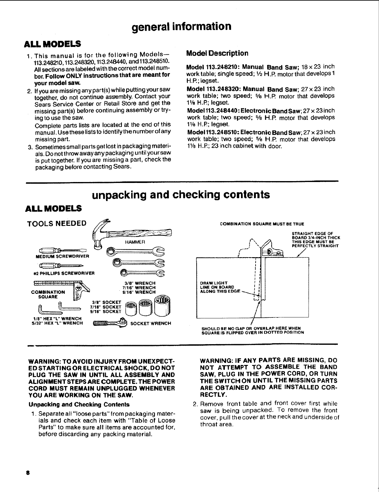
TOOLS NEEDED
MEDIUM SCREWDRIVER
PRI-,, SSCREWDRmVE. @
.......... 318" WRENCH
:_ 7/16" WRENCH
9/16" WRENCH
SQUARE _/
7116" SOCKET
9/16" SOCKET
1/8" HEX "L" WRENCH
5/32" HEX "L" WRENCH _SOCKET WRENCH
COMBINATION SQUARE MUST BE TRUE
f__./
€
STRAIGHT EDGE GF
BOARD 3/4-INCH THICK
THIS EDGE MUST BE
PER_CTLY STRAIGHT
DRAW LIGHT
LINE ON BOARD
ALONG THIS EDGIE
t,_
/
SHOULD BE NO GAP OR OVERLAP HERE WHEN
SQUARE IS FLIPPED OVER IN DOTTED POSITION
WARNING: TO AVOID INJURY FROM UNEXPECT-
ED STARTING OR ELECTRICAL SHOCK, DO NOT
PLUG THE SAW IN UNTIL ALL ASSEMBLY AND
ALIGNMENT STEPS ARE COMPLETE. THE POWER
CORD MUST REMAIN UNPLUGGED WHENEVER
YOU ARE WORKING ON THE SAW.
Unpacking and Checking Contents
1. Separate all "loose parts" from packaging mater-
ials and check each item with "Table of Loose
Parts" to make sure all items are accounted for,
before discarding any packing material.
WARNING: IF ANY PARTS ARE MISSING, DO
NOT ATTEMPT TO ASSEMBLE THE BAND
SAW, PLUG IN THE POWER CORD, OR TURN
THE SWITCH ON UNTIL THE MISSING PARTS
ARE OBTAINED AND ARE INSTALLED COR-
RECTLY.
2. Remove front table and front cover first while
saw is being unpacked. TO remove the front
cover, pull thecover at the neck and underside of
throat area.
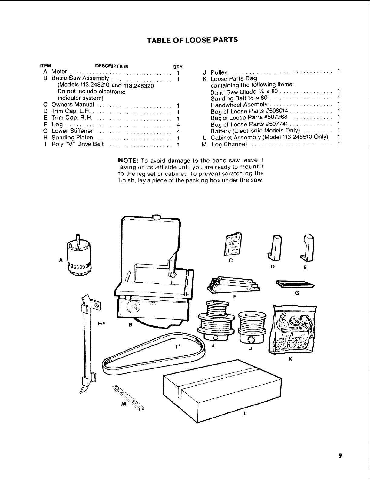
TABLE OF LOOSE PARTS
ITEM DESCRIPTION QTY.
A Motor ............................... 1
B Basic Saw Assembly .................. 1
(Models 113.248210 and 113.248320
Do not include electronic
indicator system)
C Owners Manual ....................... 1
D Trim Cap, L.H ......................... 1
E Trim Cap, R.H ........................ 1
F Leg ................................ 4
G Lower Stiffener ....................... 4
H Sanding Platen ....................... 1
I Poly "V" Drive Belt .................... 1
J Pulley ............................... 1
K Loose Parts Bag
containing the following items:
Band Saw Blade 1/4 x 80 ................ 1
Sanding Belt 1/2 x 80 ................... 1
Handwheel Asembly ................... 1
Bag of Loose Parts #508014 ............. 1
Bag of Loose Parts #507968 ............ 1
Bag of Loose Parts #507741 ............. 1
Battery (Electronic Models Only) ......... 1
L Cabinet Assembly (Model 113.248510 Only) 1
M Leg Channel ........................ 1
NOTE: To avoid damage to the band saw leave it
laying on its left side until you are ready to mount it
to the leg set or cabinet. To prevent scratching the
finish, lay a piece of the packing box under the saw.
D E
I(
ALL MODELS
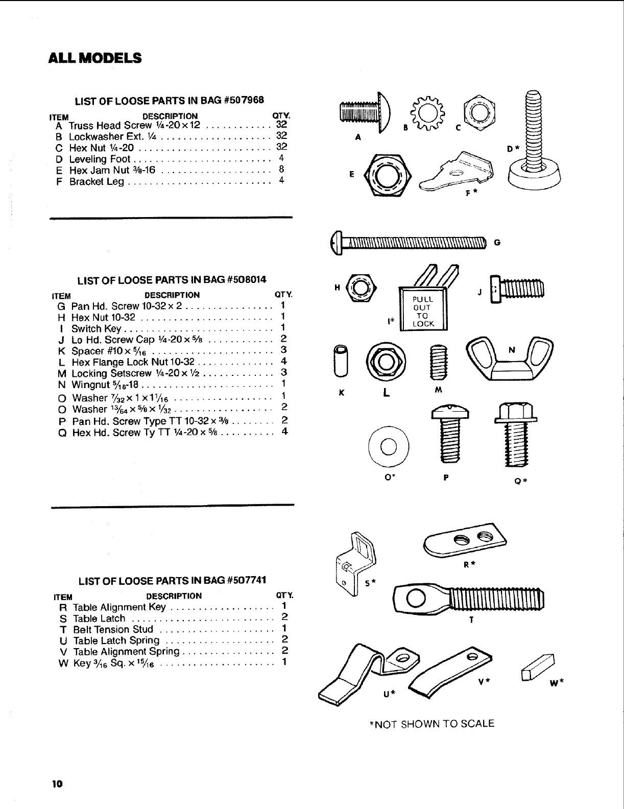
LIST OF LOOSE PARTS IN BAG #507968
ITEM DESCRIPTION QTY.
A Truss Head Screw 1/4-20x12 ............ 32
B Lockwasher Ext. t/4 .................... 32
C Hex Nut 1/4-20 ........................ 32
D Leveling Foot ......................... 4
E Hex Jam Nut 3/8-16 .................... 8
F Bracket Leg .......................... 4
LIST OF LOOSE PARTS IN BAG #508014
ITEM DESCRIPTION QTY.
G Pan Hd. Screw 10-32 x2................ 1
H Hex Nut 10-32 ........................ 1
I Switch Key ........................... 1
J Lo Hd. Screw Cap 1/4-20x si8 ............ 2
K Spacer #10 x 5As ...................... 3
L Hex Flange Lock Nut 10-32 .............. 4-
M Locking Setscrew 1/4-20x 1/2............. 3
N Wingnut %s-18 ........................ 1
O Washer 7/32x 1 x11,4s .................. 1
0 Washer 13/64x s/ex 1/32.................. 2
P Pan Hd. Screw Type TT 10-32 x 3/8 ........ 2
Q Hex Hd. Screw Ty TT 1/4-20x%.......... 4
A
_] t_\\\/\\\_\\\\\\\_\\\\\\\\\\\\\\\\\\\\\\\\\\\\\\\_e
i,v
K L M
PO*
LIST OF LOOSE PARTS IN BAG #507741
ITEM DESCRIPTION QTY.
R Table Alignment Key ................... 1
S Table Latch .......................... 2
T Belt Tension Stud ..................... 1
U Table Latch Spring .................... 2
V Table Alignment Spring ................. 2
W Key 3/16Sq. x 15,46 ..................... 1
R*
T
*NOT SHOWN TO SCALE
10
assembly and alignment
MODEL 113.248210, 113.248320,
113.248440
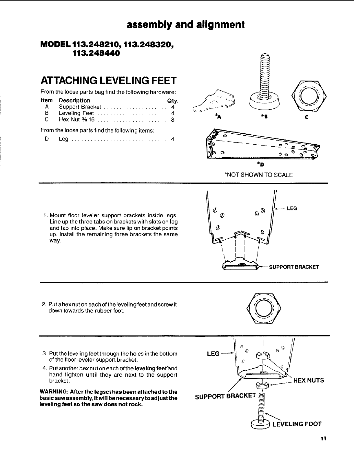
ATTACHING LEVELING FEET
From the loose parts bag find the following hardware:
Item Description Qty.
A Support Bracket .................... 4
B Leveling Feet ...................... 4
CHex Nut 3/8-16 ...................... 8
From the loose parts find the following items:
D Leg .............................. 4
_D
*NOT SHOWN TO SCALE
1. Mount floor leveler support brackets inside legs.
Line up the three tabs on brackets with slots on leg
and tap into place. Make sure lip on bracket points
up. Install the remaining three brackets the same
way.
®
LEG
SUPPORTBRACKET
2. Put a hex nut on each of the leveling feet and screw it
down towards the rubber foot.
3. Put the leveling feet through the holes in the bottom
of the floor leveler support bracket.
4. Put another hex nut on each of the leveling feet_.nd
hand tighten until they are next to the support
bracket.
WARNING: After the legset has been attached to the
basic saw assernbly, it will be necessary to adjust the
leveling feet so the saw does not rock.
NUTS
SUPPORT BRACKE ___,,.,_,.
LEVELING FOOT
11
MODEL 113.24821 O, 113.248320,
1113.248440
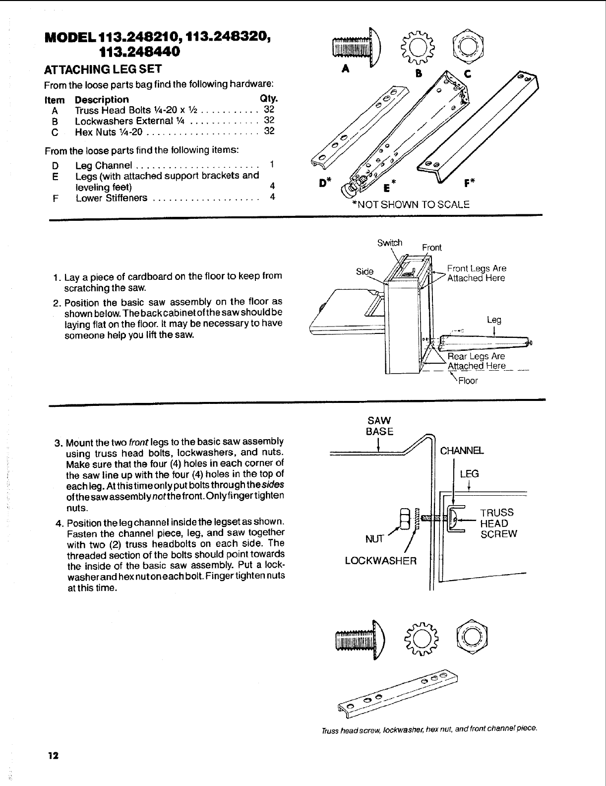
ATTACHING LEG SET
From the loose parts bag find the following hardware:
Item Description Qty.
ATruss Head Bolts 1/4.20x 1/2........... 32
B Lockwashers External 1/4 ............. 32
CHex Nuts 1/4-20 ..................... 32
From the loose parts find the following items:
D Leg Channel ....................... 1
E Legs (with attached support brackets and
leveling feet) 4
F Lower Stiffeners .................... 4 _*NOT SHOWN TO SCALE
1. Lay a piece of cardboard on the floor to keep from
scratching the saw.
2. Position the basic saw assembly on the floor as
shown below. The back cabin et of the saw should be
laying flat on the floor. It may be necessary to have
someone help you lift the saw.
Switch
=_ont
Side ,/_/_J_//_1 __.Front Leg s Are
tt__._ _ Artac bed Here
_ Leg
J[ t_'/ \ Rear Legs Are
L_._/_Attached_ __ _ Here
\ Floor
3. Mount the two front legs to the basic saw assembly
using truss head bolts, Iockwashers, and nuts.
Make sure that the four (4) holes in each corner of
the saw line up with the four (4) holes in the top of
each leg. At this time only put bolts through thesides
of the saw assembly notthe front. Onlyfinger tighten
nuts.
4. Position the leg channel inside the legset as shown.
Fasten the channel piece, leg, and saw together
with two (2) truss headbolts on each side. The
threaded section of the bolts should point towards
the inside of the basic saw assembly. Put a lock-
washer and hex nuton each bolt. Finger tighten nuts
atthis time.
SAW
BAS E
LEG
!
LOCKWASHER
TRUSS
HEAD
SCREW
Trusshead screw, Iockwasher, hex nut, and front channel piece.
12
.
.
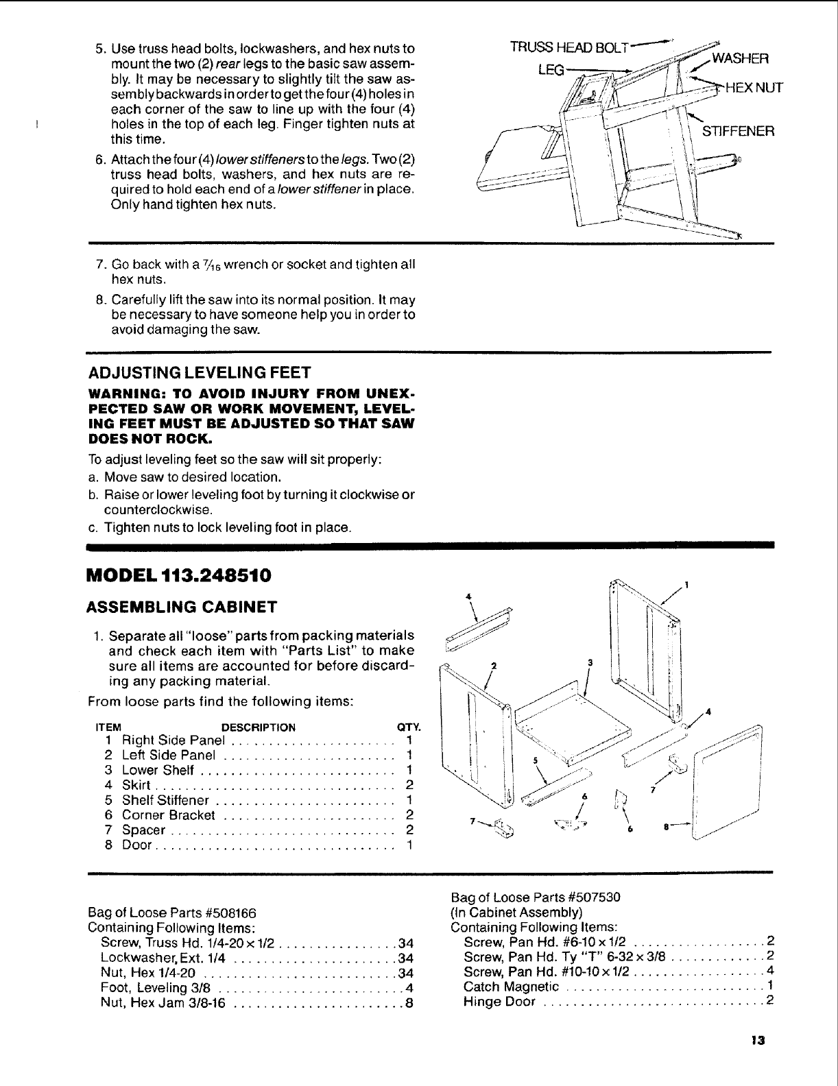
Use truss head bolts, Iockwashers, and hex nuts to
mount the two (2) rear legs to the basic saw assem-
bly. It may be necessary to slightly tilt the saw as-
sembly backwards in order to get the four (4)holes in
each corner of the saw to line up with the four (4)
holes in the top of each leg. Finger tighten nuts at
this time.
Attach the four (4) lower stiffeners to the legs. Two (2)
truss head bolts, washers, and hex nuts are re-
quired to hold each end of alowerstiffener in place.
Only hand tighten hex nuts.
TRUSS HEAD BOLT "-'-'_' .-J.__
,._j_ WASHER
LEG . _ _S_/_ :1iHEXNu,
///_ ,,/LL_--_ --
i S FFE.ER
7. Go back with a 7/_6wrench or socket and tighten all
hex nuts.
8. Carefully lift the saw into its normal position. It may
be necessary to have someone help you in order to
avoid damaging the saw.
ADJUSTING LEVELING FEET
WARNING: TO AVOID INJURY FROM UNEX-
PECTED SAW OR WORK MOVEMENT, LEVEL-
ING FEET MUST BE ADJUSTED SO THAT SAW
DOES NOT ROCK.
To adjust leveling feet so the saw will sit properly:
a. Move saw to desired location.
b. Raise or lower leveling foot by turning it clockwise or
counterclockwise.
c. Tighten nuts to lock leveling foot in place.
MODEL 113.248510
ASSEMBLING CABINET
1. Separate all "loose" parts from packing materials
and check each item with "Parts List" to make
sure all items are accounted for before discard-
ing any packing material.
From loose parts find the following items:
ITEM DESCRIPTION QTY.
1 Right Side Panel ...................... 1
2 Left Side Panel ....................... 1
3 Lower Shelf .......................... 1
4 Skirt ................................ 2
5 Shelf Stiffener ........................ 1
6 Corner Bracket ....................... 2
7 Spacer .............................. 2
8 Door ................................ 1
Bag of Loose Parts #508166
Containing Following Items:
Screw, Truss Hd. 1/4-20 x 1/2 ................ 34
Lockwasher, Ext. 1/4 ...................... 34
Nut, Hex 1/4-20 .......................... 34
Foot, Leveling 3/8 ......................... 4
Nut, Hex Jam 3/8-16 ....................... 8
Bag of Loose Parts #507530
(In Cabinet Assembly)
Containing Following Items:
Screw, Pan Hd. #6-10 x 1/2 .................. 2
Screw, Pan Hd. Ty "T" 6-32 x 318 ............. 2
Screw, Pan Hd. #10-10x 1/2 .................. 4
Catch Magnetic ........................... 1
Hinge Door .............................. 2
13
MODEL 113.248510
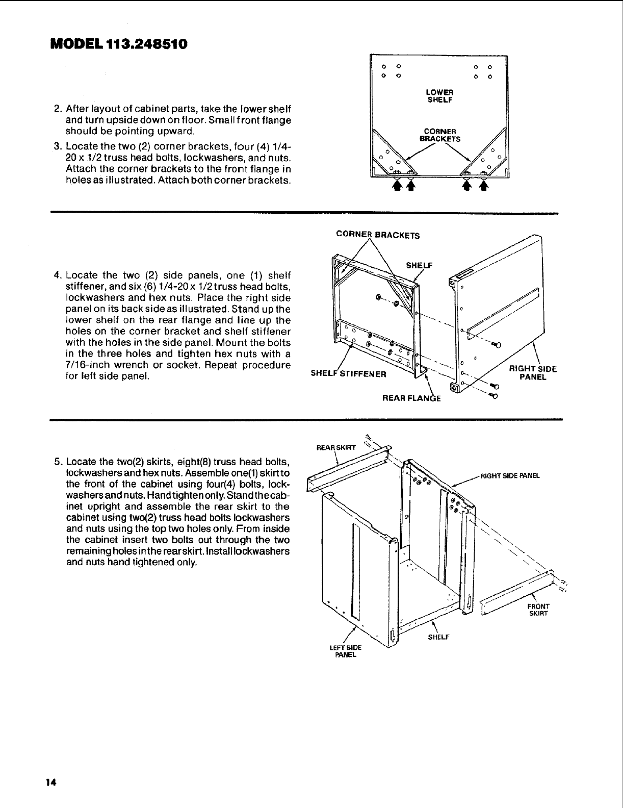
2. After layout of cabinet parts, take the lower shelf
and turn upside down on floor. Small front flange
should be pointing upward.
3. Locate the two (2) corner brackets, four (4) 1/4-
20 x 1/2 truss head bolts, Iockwashers, and nuts.
Attach the corner brackets to the front flange in
holes as illustrated. Attach both corner brackets.
o o o o
o o o o
LOWER
SHELF
CORNER /_
BRACKETS 7_
\ ,/:o:
CORNER BRACKETS
4. Locate the two (2) side panels, one (1) shelf
stiffener, and six (6) 1/4-20 x 1/2truss head bolts,
Iockwashers and hex nuts. Place the right side
panel on its back side as illustrated. Stand up the
lower shelf on the rear flange and line up the
holes on the corner bracket and shelf stiffener
with the holes in the side panel. Mount the bolts
in the three holes and tighten hex nuts with a
7/16-inch wrench or socket. Repeat procedure
for left side panel.
SHELF
RIGHT SIDE
SHELF STIFFENER PANEL
REAR FLANGE
5. Locate the two(2) skirts, eight(8) truss head bolts,
Iockwashers and hex nuts. Assemble one(l) skirt to
the front of the cabinet using four(4) bolts, lock-
washers and nuts. Hand tighten only. Stand the cab-
inet upright and assemble the rear skirt to the
cabinet using two(2) truss head bolts Iockwashers
and nuts using the top two holes only. From inside
the cabinet insert two bolts out through the two
remaining holes in the rearskirt. Installlockwashers
and nuts hand tightened only.
REAR SKIRT
/...i RIGHT SIDE PANEL
\\
FRONT
SKIRT
LEFT SI DE
PANEL
SHELF
14
MODEL 113.248510
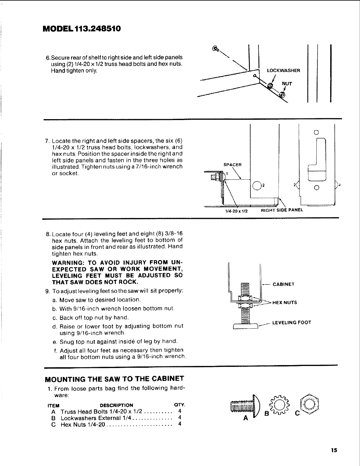
6.Secure rear of shelf to right side and left side panels
using (2) 1/4-20 x 1/2 truss head bolts and hex nuts.
Hand tighten only. LOCKWASHER
NUT
I
7. Locate the right and left side spacers, the six (6)
1/4-20 x 1/2 truss head bolts, Iockwashers, and
hex nuts. Position the spacer inside the right and
left side panels and fasten in the three holes as
illustrated. Tighten nuts using a 7/16-inch wrench
or socket.
SPACER
2
©
©
1/'4-20 x1!2 RIGHT SIDE PANEL
g.
Locate four (4) leveling feet and eight (8) 3/8-16
hex nuts. Attach the leveling feet to bottom of
side panels in front and rear as illustrated. Hand
tighten hex nuts.
WARNING: TO AVOID INJURY FROM UN-
EXPECTED SAW OR WORK MOVEMENT,
LEVELING FEET MUST BE ADJUSTED SO
THAT SAW DOES NOT ROCK.
To adjust leveling feet so the saw will sit properly:
a. Move saw to desired location.
b. With 9/16-inch wrench loosen bottom nut.
c. Back off top nut by hand.
d. Raise or lower foot by adjusting bottom nut
using 9/16-inch wrench.
e. Snug top nut against inside of leg by hand.
f. Adjust all four feet as necessary then tighten
all four bottom nuts using a 9/16-inch wrench.
MOUNTING THE SAW TO THE CABINET
1, From loose parts bag find the following hard-
ware:
ITEM DESCRIPTION QTY.
A Truss Head Bolts 1/4-20 x 1/2 .......... 4
BLockwashers External 1/4 .............. 4
C Hex Nuts 1/4-20 ....................... 4
c©
t5
MODEL 113.248510
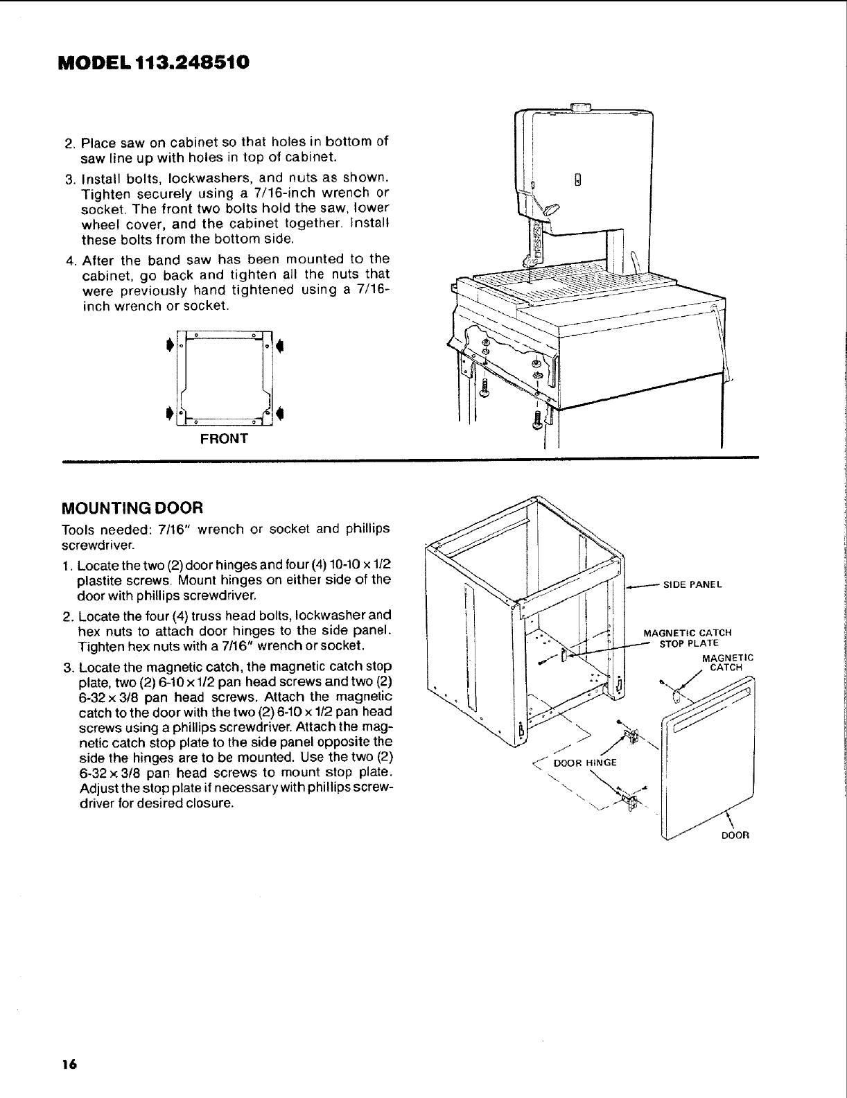
2. Place saw on cabinet so that holes in bottom of
saw line up with holes in top of cabinet.
3. Install bolts, Iockwashers, and nuts as shown.
Tighten securely using a 7/16-inch wrench or
socket. The front two bolts hold the saw, lower
wheel cover, and the cabinet together. Install
these bolts from the bottom side,
4. After the band saw has been mounted to the
cabinet, go back and tighten all the nuts that
were previously hand tightened using a 7/16-
inch wrench or socket.
FRONT
MOUNTING DOOR
Tools needed: 7/16" wrench or socket and phillips
screwdriver.
1. Locate the two (2) door hinges and four (4) 10-10 x1t2
plastite screws. Mount hinges on either side of the
door with phillips screwdriver.
2. Locate the four (4) truss head bolts, Iockwasher and
hex nuts to attach door hinges to the side panel.
Tighten hex nuts with a 7/16" wrench or socket.
3. Locate the magnetic catch, the magnetic catch stop
plate, two (2) 6-10 x 1/2 pan head screws and two (2)
6-32 x 3t8 pan head screws. Attach the magnetic
catch to the door with the two (2) 6-10 x 1/2 pan head
screws using a phillips screwdriver. Attach the mag-
netic catch stop plate to the side panel opposite the
side the hinges are to be mounted. Use the two (2)
6-32 x 3/8 pan head screws to mount stop plate.
Adjust the stop plate if necessary with phillips screw-
driver for desired closure.
;IDE PANEL
MAGNETIC CATCH
STOP PLATE
MAGNETIC
CATCH
16
ALL MODELS
ATTACHING THE HANDWHEEL
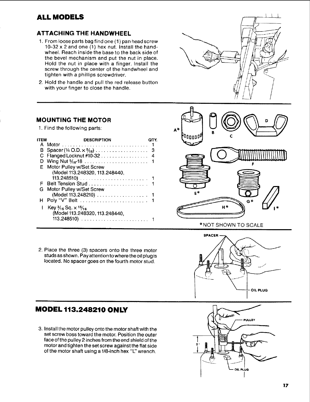
1. From loose parts bag find one (1) pan head screw
10-32 x 2 and one (1) hex nut. Install the hand-
wheel. Reach inside the base to the back side of
the bevel mechanism and put the nut in place.
Hold the nut in place with a finger. Install the
screw through the center of the handwheel and
tighten with a phillips screwdriver.
2. Hold the handle and pull the red release button
with your finger to close the handle.
1
7
_T _-_
( i¸ '
MOUNTING THE MOTOR
1. Find the following parts:
ITEM DESCRIPTION QTY.
A Motor ............................... 1
B Spacer(I/40.D. x %6) ................... 3
C Flanged Locknut #10-32 ................. 4
D Wing Nut %6-18 ....................... 1
E Motor Pulleyw/Set Screw
(Model 113.248320, 113.248440,
113.248510) ........................ 1
F Belt Tension Stud ..................... 1
G Motor Pulleyw/Set Screw
(Model 113.248210) .................. 1
H Poly "V" Belt ........................ 1
I Key 3/%Sq. x 1%6
(Model 113.248320, 1!3.248440,
113.248510) ........................ 1
F
*NOT SHOWN TO SCALE
2. Place the three (3) spacers onto the three motor
studs as shown. Pay attention to where the oil plug is
located. No spacer goes on the fourth motor stud.
MODEL 113.248210 ONLY
3. Install the motor pulley onto the motor shaft with the
set screw boss toward the motor. Position the outer
face of the pulley 2 inches from the end shield of the
motor and tighten the set screw against the flat side
of the motor shaft using a 1/8-inch hex "E' wrench.
1
1
OIL PLUG
r
- OIL PLUG
17
MODELS 113.248320,
113.248440, and
113.248510
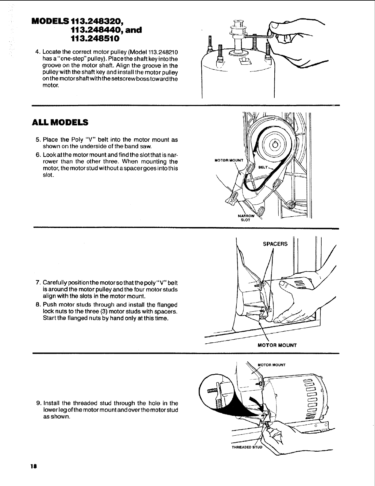
4. Locate the correct motor pulley (Model 113.248210
has a "one-step" pulley). Placethe shaft key intothe
groove on the motor shaft. Align the groove in the
pulley with the shaft key and install the motor pulley
on the motor shaft with the setscrew boss toward the
motor.
ALL MODELS
5. Place the Poly "V" belt into the motor mount as
shown on the underside of the band saw.
6. Look atthe motor mount and find the slot that is nar-
rower than the other three. When mounting the
motor, the motor stud without a spacer goes into this
slot.
MOTOR MOUNT
NARROW
SLOT
7. Carefully position the motor sothat the poly"V" belt
is around the motor pulley and the four motor studs
align with the slots in the motor mount.
8. Push motor studs through and install the flanged
lock nuts to the three (3) motor studs with spacers.
Start the flanged nuts by hand only at this time.
MOTOR MOUNT
9. Install the threaded stud through the hole in the
lower leg of the motor mount and over the motor stud
as shown.
MOTOR MOUNT
THREADED STUD
18
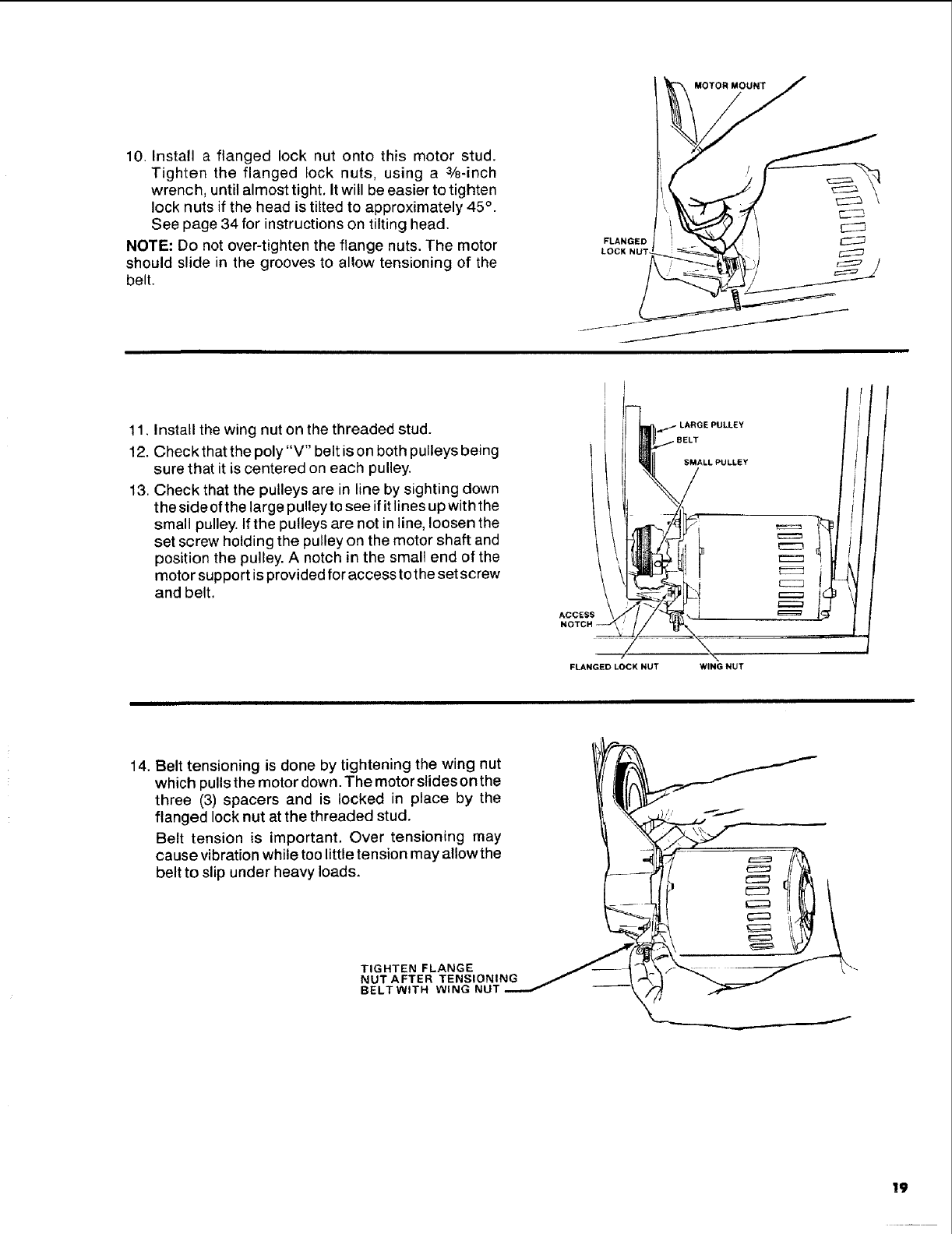
10. Install a flanged lock nut onto this motor stud.
Tighten the flanged lock nuts, using a %-inch
wrench, until almost tight. It will be easier to tighten
lock nuts if the head is tilted to approximately 45 ° .
See page 34 for instructions on tilting head.
NOTE: Do not over-tighten the flange nuts. The motor
should slide in the grooves to allow tensioning of the
belt.
_//- /
11. Install the wing nut on the threaded stud.
12. Check that the poly "V" belt is on both pulleys being
sure that it is centered on each pulley.
13. Check that the pulleys are in line by sighting down
the side of the large pulley te see if it lines up with the
small pulley. If the pulleys are not in line, loosen the
set screw holding the pulley on the motor shaft and
position the pulley. A notch in the small end of the
motor support is provided for access to the set screw
and belt.
SMALLPULLEY
FLANGED LOCK NUT WING NUT
J!J/
14. Belt tensioning is done by tightening the wing nut
which pulls the motor down. The motor slides on the
three (3) spacers and is locked in place by the
flanged lock nut at the threaded stud.
Belt tension is important. Over tensioning may
cause vibration while too little tension may allowthe
belt to slip under heavy loads,
TIGHTEN FLANGE
NUT AFTER TENSIONING
BELTWITH WING NUT
19
ALL MODELS
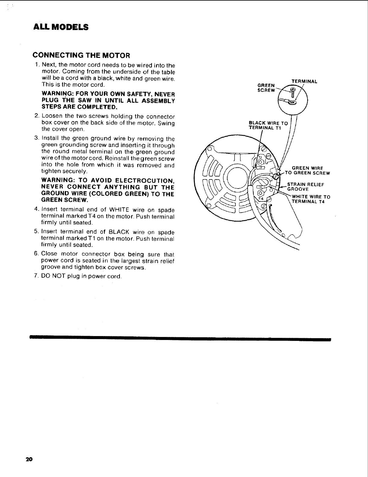
CONNECTING THE MOTOR
1. Next, the motor cord needs to be wired into the
motor. Coming from the underside of the table
will be a cord with a black, white and green wire.
This is the motor cord.
WARNING: FOR YOUR OWN SAFETY, NEVER
PLUG I_HE SAW IN UNTIL ALL ASSEMBLY
STEPS ARE COMPLETED.
2. Loosen the two screws holding the connector
box cover on the back side of the motor. Swing
the cover open.
3. Install the green ground wire by removing the
green grounding screw and inserting it through
the round metal terminal on the green ground
wire of the motor cord. Reinstall the green screw
into the hole from which it was removed and
tighten securely.
WARNING: TO AVOID ELECTROCUTION,
NEVER CONNECT ANYTHING BUT THE
GROUND WIRE (COLORED GREEN) TO THE
GREEN SCREW.
4. Insert terminal end of WHITE wire on spade
terminal marked T4 on the motor. Push terminal
firmly until seated.
5. Insert terminal end of BLACK wire on spade
terminal marked T1 on the motor. Push terminal
firmly until seated.
6. Close motor connector box being sure that
power cord is seated in the largest strain relief
groove and tighten box cover screws.
7. DQ NOT plug in power cord.
GREEN
BLACK WIRE
TERMINAL Tt
TERMINAL
GREEN WIRE
.TO GREEN SCREW
STRAIN RELIEF
WtRE TO
TERMINAL T4
2O
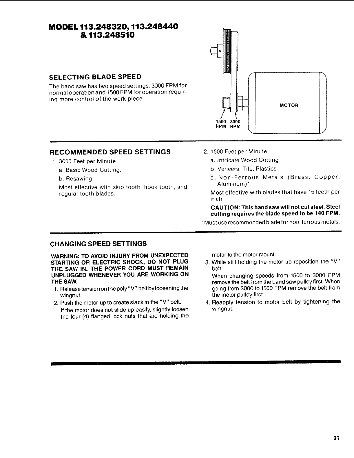
MODEL 113.248320, 113.248440
& 113.248510
SELECTING BLADE SPEED
The band saw has two speed settings: 3000 FPM for
normal operation and 1500 FPM for operation requir-
ing more control of the work piece,
1500 3000
RPM RPM
MOTOR
J
RECOMMENDED SPEED SETTINGS
1. 3000 Feet per Minute
a. Basic Wood Cutting.
b. Resawing
Most effective with skip tooth, hook tooth, and
regular tooth blades.
2. 1500 Feet per Minute
a. Intricate Wood Cutting
b. Veneers, Tile, Plastics
c. Non-Ferrous Metals (Brass, Copper,
Aluminum)*
Most effective with blades that have 15 teeth per
inch.
CAUTION: This band saw will not cut steel. Steel
cutting requires the blade speed to be 140 FPM.
*Must use recommended blade for non-ferrous metals.
CHANGING SPEED SETTINGS
WARNING: TO AVOID INJURY FROM UNEXPECTED
STARTING OR ELECTRIC SHOCK, DO NOT PLUG
THE SAW IN. THE POWER CORD MUST REMAIN
UNPLUGGED WHENEVER YOU ARE WORKING ON
THE SAW,
1. Releasetension onthe poly "V" belt by Iooseningthe
wingnut,
2. Push the motor up to create slack in the "V" belt.
If the motor does not slide up easily, slightly loosen
the four (4) flanged lock nuts that are holding the
motor to the motor mount.
3. While still holding the motor up reposition the "V"
belt.
When changing speeds from 1500 to 3000 FPM
remove the belt from the band saw pulley first. When
going from 3000 to 1500 FPM remove the belt from
the motor pulley first.
4. Reapply tension to motor belt by tightening the
wingnut.
21
ALL MODELS
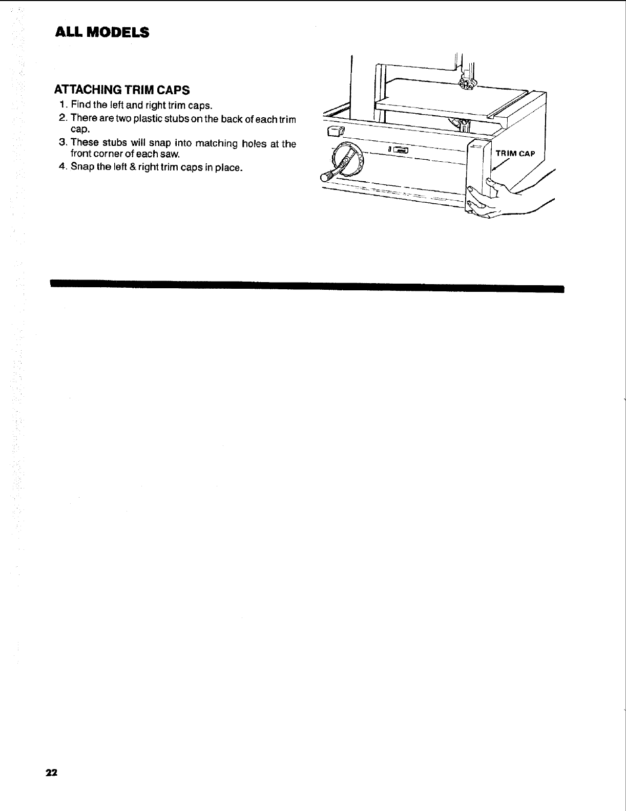
ATTACHING TRIM CAPS
1. Find the left and right trim caps.
2. There are two plastic stubson the back of each trim
cap.
3. These stubs will snap into matching holes at the
front corner of each saw.
4. Snap the left & right trim caps in place.
TRIM CAP
22
getting to know your band saw
2
TENSION ADJUSTMENT KNOB
COVER
1
WARNING LABEL
BEVEL
BLADE GUARD
WARNING
LABEL BEVEL
4
BEVEL LOCK KNOB
GAGE
SLOT
BLADE GUIDES
HANDWHEEL
ON-OFF SWITCH
3
ELECTRONIC/INDICATOR
SYSTEM 7
MODELS 113.248440 and BACK-UPBEA.,NG
113.248510
HAND
WHEEL
MODELS113.248210an¢
113.248320
BACKUP BEARING
5+ 0
JIDES
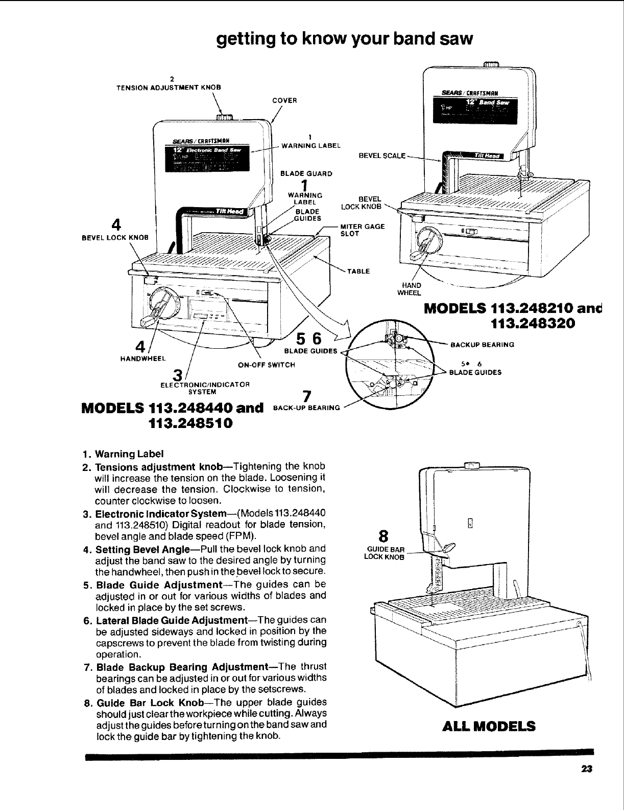
1. Warning Label
2. Tensions adjustment knob--Tightening the knob
will increase the tension on the blade. Loosening it
will decrease the tension. Clockwise to tension,
counter clockwise to loosen.
3. Electronic IndicatorSystem--(Models113.248440
and 113.248510) Digital readout for blade tension,
bevel angle and blade speed (FPM).
4. Setting Bevel Angle--Pull the bevel lock knob and
adjust the band saw to the desired angle by turning
the handwheel, then push in the bevel lockto secure.
5. Blade Guide Adjustment--The guides can be
adjusted in or out for various widths of blades and
locked in place by the set screws.
6. Lateral Blade Guide Adjustment--The guides can
be adjusted sideways and locked in position by the
capscrews to prevent the blade from twisting during
operation.
7. Blade Backup Bearing Adjustment--The thrust
bearings can be adjusted in or out for various widths
of blades and locked in place by the setscrews.
8. Guide Bar Lock Knob--The upper blade guides
should justclear the workpiece while cutting. Always
adjust the guides before turning on the band saw and
lock the guide bar by tightening the knob.
8
GUIDE BAR
LOCK KNOB
ALL MODELS
23
location and function of the electronic indicator system
MODEL 113.248440 & 113.248510 ON LY
BATTERY COVER RELEASE SLOTS
&OPEN BATTERY OPEN •
BATTERY COVER
KEY
ELECTRONIC
MEASUREMENT
BEVEL ANGLE KEY
SION KEY
SPEED KEY (FT. PER MIN.)
_ IEFERENCE SET KEY
DIGITAL READOUT DISPLAY
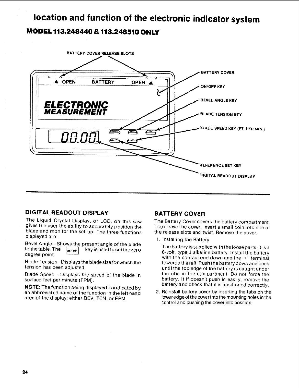
DIGITAL READOUT DISPLAY
The Liquid Crystal Display, or LCD, on this saw
gives the user the ability to accurately position the
blade and monitor the set-up. The three functions
displayed are:
Bevel Angle - Shows the present angle of the blade
to the table. The _ keyis used toset thezero
degree point.
Blade Tension - Displays the blade size for which the
tension has been adjusted.
Blade Speed - Displays the speed of the blade in
surface feet per minute (FPM).
NOTE: The function being displayed is indicated by
an abbreviated name of the function in the left hand
area of the display; either BEV, TEN, or FPM.
BATTERY COVER
The Battery Cover covers the battery compartment,
To.release the cover, insert a small coin into one of
the release slots and twist. Remove the cover.
1. Installing the Battery
The battery is supplied with the loose parts. It is a
6-volt, type J alkaline battery. Install the battery
with the contact end down and the "+" terminal
towards the left. Push the battery down and back
until the top edge of the battery is caught under
the ribs in the compartment. Do not force the
battery. It if doesn't push in easily, remove the
battery and check that it is positioned correctly.
2. Reinstall battery cover by inserting the tabs on the
lower edge of the cover into the mounting holes in the
control and pushing the cover into position.
24
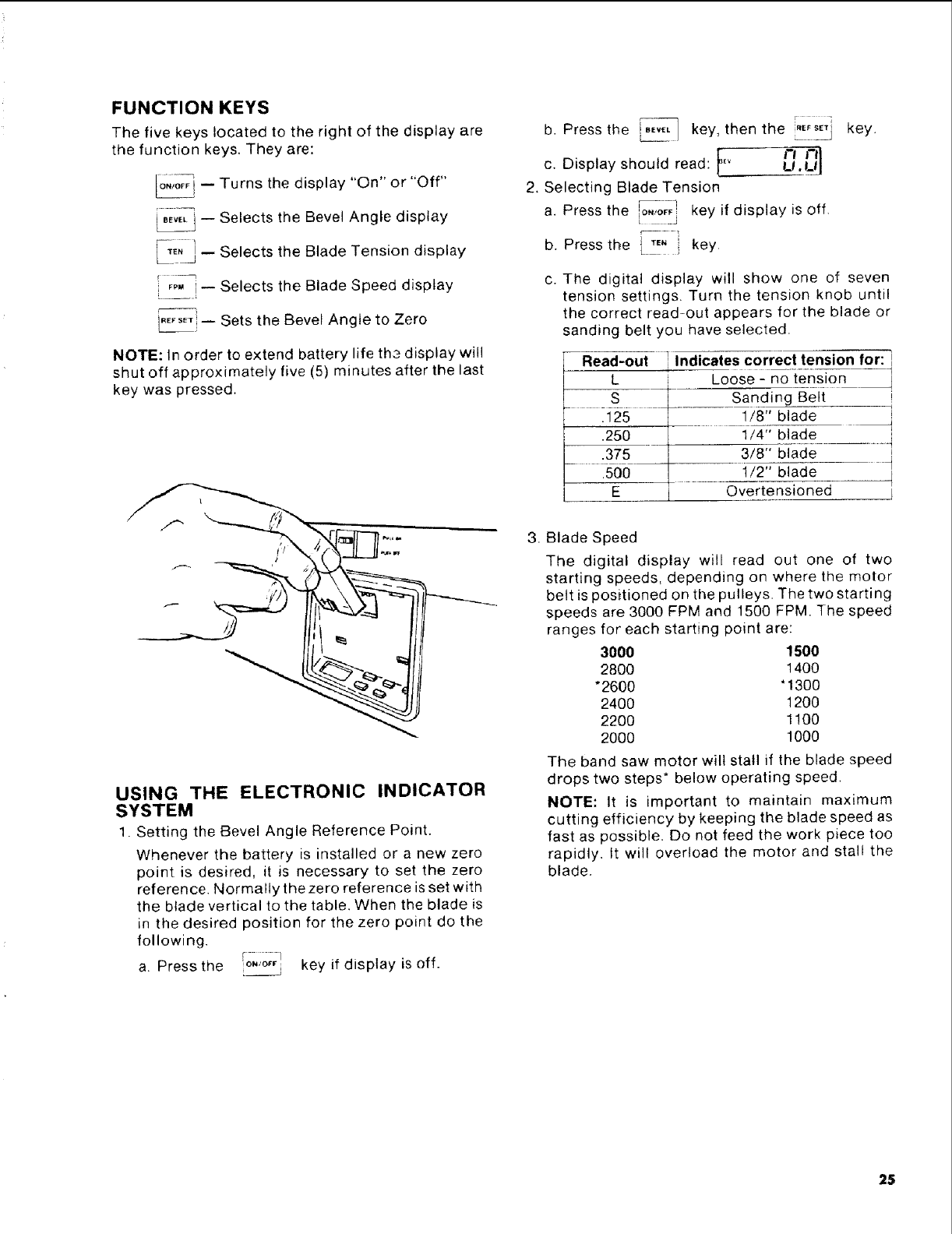
FUNCTION KEYS
The five keys located to the right of the display are
the function keys. They are:
io._o_ -- Turns the display "On" or "Off"
_j -- Selects the Bevel Angle display
i-_. _j-- Selects the Blade Tension display
E_p_- Selects the Blade Speed display
-- Sets the Bevel Angle to Zero
NOTE: In order to extend battery life the display will
shut off approximately five (5) minutes after the last
key was pressed.
USING THE ELECTRONIC INDICATOR
SYSTEM
1. Setting the Bevel Angle Reference Point.
Whenever the battery is installed or a new zero
point is desired, it is necessary to set the zero
reference. Normally the zero reference is set with
the blade vertical to the table. When the blade is
in the desired position for the zero point do the
following.
a. Press the IONIOFI¢I key if display is off.
b. Press the _E._--_ key, then the ._,s_j
F '-'ic. Display should read: _v U.U
2. Selecting Blade Tension
n
a. Press the IoF_.IQF_!key if display is off.
b. Press the _ T,. key.
key.
c. The digital display will show one of seven
tension settings. Turn the tension knob until
the correct read-out appears for the blade or
sanding belt you have selected.
Read-out iIndicates correct tension for:
L Loose - no tension
S Sanding Belt
.125 1/8" blade
.250 1/4" blade
.375 3/8" blade
.500 1/2" blade
E Overtensioned
3. Blade Speed
The digital display will read out one of two
starting speeds, depending on where the motor
belt is positioned on the pulleys. The two starting
speeds are 3000 FPM and 1500 FPM. The speed
ranges for each starting point are:
3000 1500
2800 1400
*2600 '1300
2400 1200
2200 1100
2OOO 1000
The band saw motor wilt stall if the blade speed
drops two steps* below operating speed,
NOTE: It is important to maintain maximum
cutting efficiency by keeping the blade speed as
fast as possible. Do not feed the work piece too
rapidly, tt will overload the motor and stall the
blade,
25
ALL MODELS
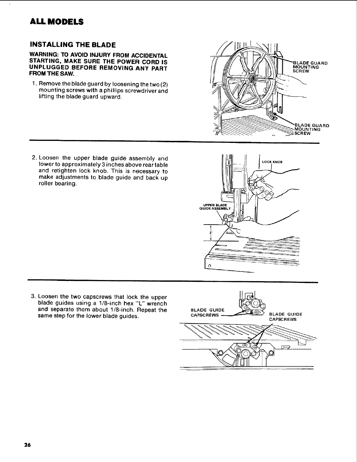
INSTALLING THE BLADE
WARNING: TO AVOID INJURY FROM ACCIDENTAL
STARTING, MAKE SURE THE POWER CORD IS
UNPLUGGED BEFORE REMOVING ANY PART
FROM THE SAW.
1. Remove the blade guard by loosening the two (2)
mounting screws with a phillips screwdriver and
lifting the blade guard upward.
.IGNUGARD
2. Loosen the upper blade guide assembly and
lower to approximately 3 inches above rear table
and retighten lock knob. This is necessary to
make adjustments to blade guide and back up
roller bearing.
|_.j LOCK KNOB
Jrt[,t] I
3. Loosen the two capscrews that lock the upper
blade guides using a 1/8-inch hex "L,' wrench
and separate them about 1/8-inch. Repeat the
same step for the lower blade guides. BLADE GUIDE
CAPSCREWS
26
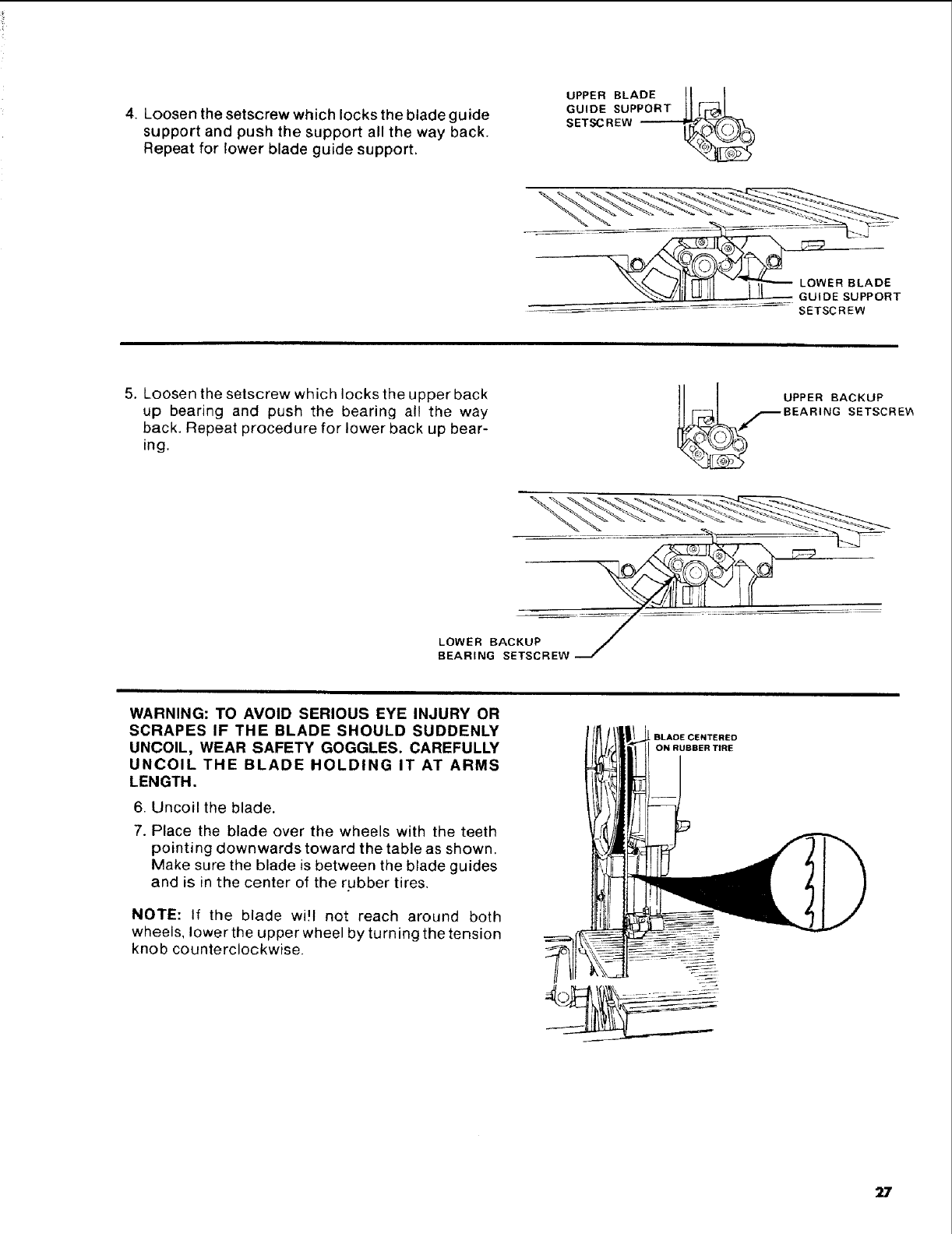
4. Loosen the setscrew which locks the blade guide
support and push the support all the way back.
Repeat for lower blade guide support.
UPPERBLADE tl t
GU,DEsuPPO.TII_l-r L
SETSCREW _
"<_-_-"_,J/l[I L.U ql I '1 GUIDE SUPPORT
_---_--_--'=_ SETSCREW
5. Loosen the setscrew which locks the upper back
up bearing and push the bearing all the way
back. Repeat procedure for lower back up bear-
ing.
_f UPPER BACKUP
BEAR NG SETSCRE_
LOWER BACKUP
BEARING SETSCREW
WARNING: TO AVOID SERIOUS EYE INJURY OR
SCRAPES IF THE BLADE SHOULD SUDDENLY
UNCOIL, WEAR SAFETY GOGGLES. CAREFULLY
UNCOIL THE BLADE HOLDING IT AT ARMS
LENGTH.
6. Uncoil the blade.
7. Place the blade over the wheels with the teeth
pointing downwards toward the table as shown.
Make sure the blade is between the blade guides
and is in the center of the rubber tires.
NOTE: If the blade wi!t not reach around both
wheels, lower the upper wheel by turning the tension
knob counterclockwise.
BLADE CENTERED
ON RUBBER TIRE
27
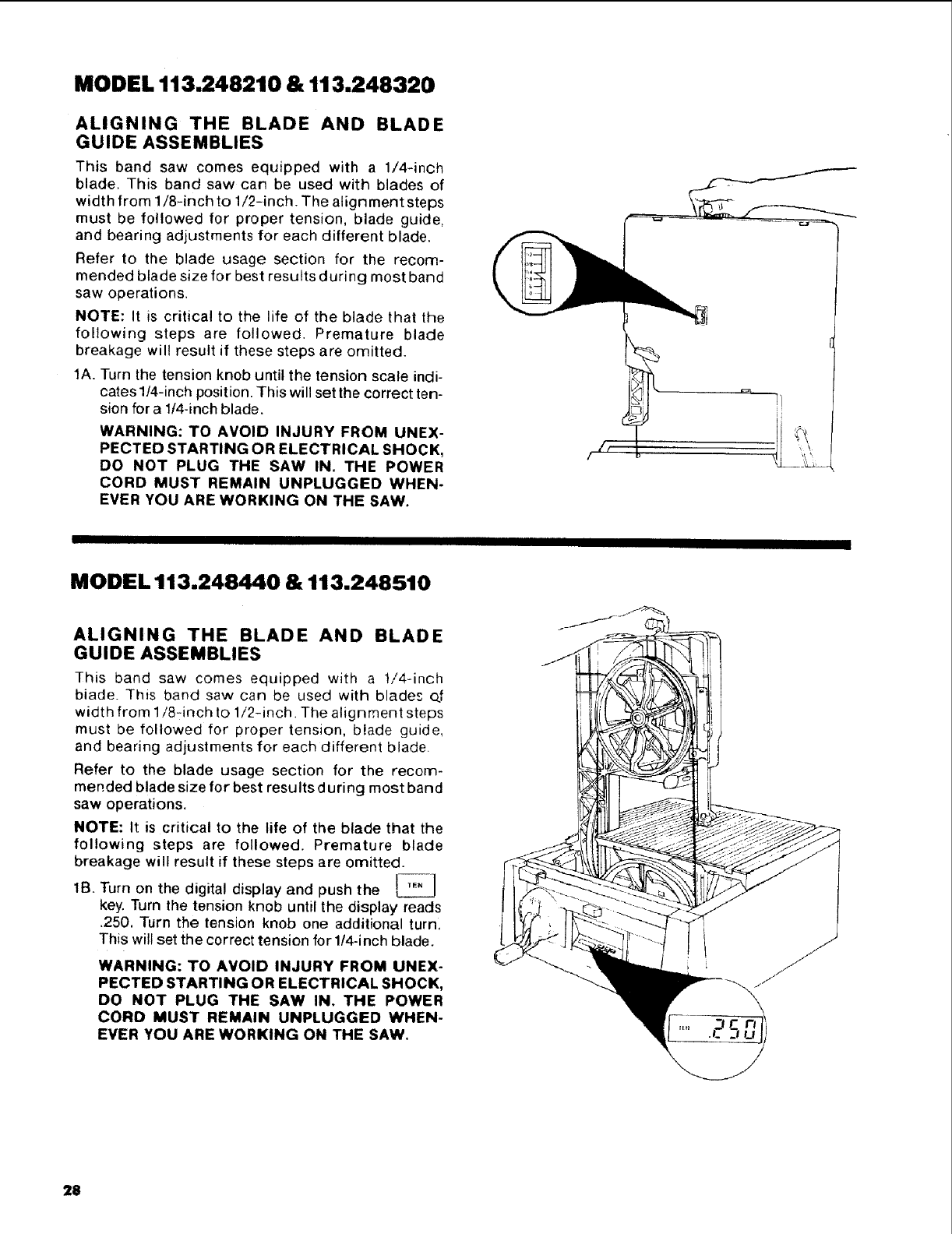
MODEL 113.248210 & 113.248320
ALIGNING THE BLADE AND BLADE
GUIDE ASSEMBLIES
This band saw comes equipped with a 1/4-inch
blade, This band saw can be used with blades of
width from 1/8-inch to 1/2-inch. The align merit steps
must be followed for proper tension, blade guide,
and bearing adjustments for each different blade.
Refer to the blade usage section for the recom-
mended blade size for best results during most band
saw operations.
NOTE: It is critical to the life of the blade that the
following steps are followed. Premature blade
breakage wilt result if these steps are omitted.
1A. Turn the tension knob until the tension scale indi-
cates 1/4-inch position. This will set the correct ten-
sion for a lt4-inch blade.
WARNING: TO AVOID INJURY FROM UNEX-
PECTED STARTING OR ELECTRICAL SHOCK,
DO NOT PLUG THE SAW IN. THE POWER
CORD MUST REMAIN UNPLUGGED WHEN-
EVER YOU ARE WORKING ON THE SAW.
MODEL 113.248440 & 113.248510
ALIGNING THE BLADE AND BLADE
GUIDE ASSEMBLIES
This band saw comes equipped with a 1/4-inch
biade. This band saw can be used with blades o.f
width from 1/8-inch to 1/2-inch. The alignment steps
must be followed for proper tension, blade guide,
and bearing adjustments for each different blade.
Refer to the blade usage section for the recom-
mended blade size for best results during most band
saw operations.
NOTE: It is critical to the life of the blade that the
following steps are followed. Premature blade
breakage wilt result if these steps are omitted.
lB. Turn on the digital display and push the
key. Turn the tension knob until the display reads
.250, Turn the tension knob one additional turn,
This wilt set the correct tension for 1/4-inch blade.
WARNING: TO AVOID INJURY FROM UNEX-
PECTED STARTING OR ELECTRICAL SHOCK,
DO NOT PLUG THE SAW IN. THE POWER
CORD MUST REMAIN UNPLUGGED WHEN-
EVER YOU ARE WORKING ON THE SAW.
28
ALL MODELS
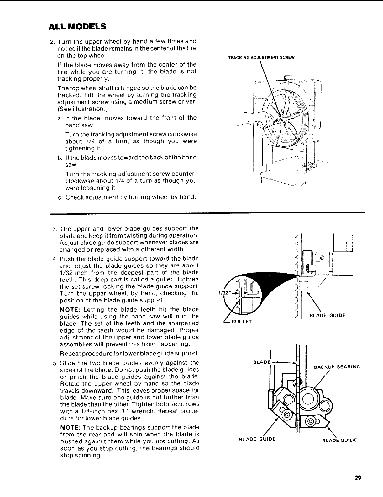
2. Turn the upper wheel by hand a few times and
notice if the blade remains in the center of the tire
on the top wheel.
If the blade moves away from the center of the
tire while you are turning it, the blade is not
tracking properly.
The top wheel shaft is hinged so the blade can be
tracked. Tilt the wheel by turning the tracking
adjustment screw using a medium screw driver.
(See illustration.)
a. If the bladel moves toward the front of the
band saw:
Turn the tracking adjustment screw clockwise
about 1/4 of a turn, as though you were
tightening it.
b. If the blade moves toward the back of the band
saw:
Turn the tracking adjustment screw counter-
clockwise about 1/4 of a turn as though you
were loosening it.
c. Check adjustment by turning wheel by hand.
TRACKING ADJUSTMENT SCREW
3. The upper and lower blade guides support the
blade and keep it from twisting during operation.
Adjust blade guide support whenever blades are
changed or replaced with a different width.
4. Push the blade guide support toward the blade
and adjust the blade guides so they are about
1/32-inch from the deepest part of the blade
teeth. This deep part is called a gullet. Tighten
the set screw locking the blade guide support.
Turn the upper wheel, by hand, checking the
position of the blade guide support.
NOTE: Letting the blade teeth hit the blade
guides while using the band saw will ruin the
blade. The set of the teeth and the sharpened
edge of the teeth would be damaged. Proper
adjustment of the upper and lower blade guide
assemblies will prevent this from happening.
Repeat procedu re for lower blade guide support.
5. Slide the two blade guides evenly against the
sides of the blade. Do not push the blade guides
or pinch the blade guides against the blade.
Rotate the upper wheel by hand so the blade
travels downward. This leaves proper space for
blade. Make sure one guide is not further from
the blade than the other. Tighten both setscrews
with a 1/8-inch hex "L" wrench, Repeat proce-
dure for lower blade guides.
NOTE: The backup bearings support the blade
from the rear and will spin when the blade is
pushed against them while you are cutting, As
soon as you stop cutting, the bearings should
stop spinning.
GULLET
BLADE GUIDE
29
BL BEARING
BLADE GUIDE BLADE GUIDE
ALL MODELS
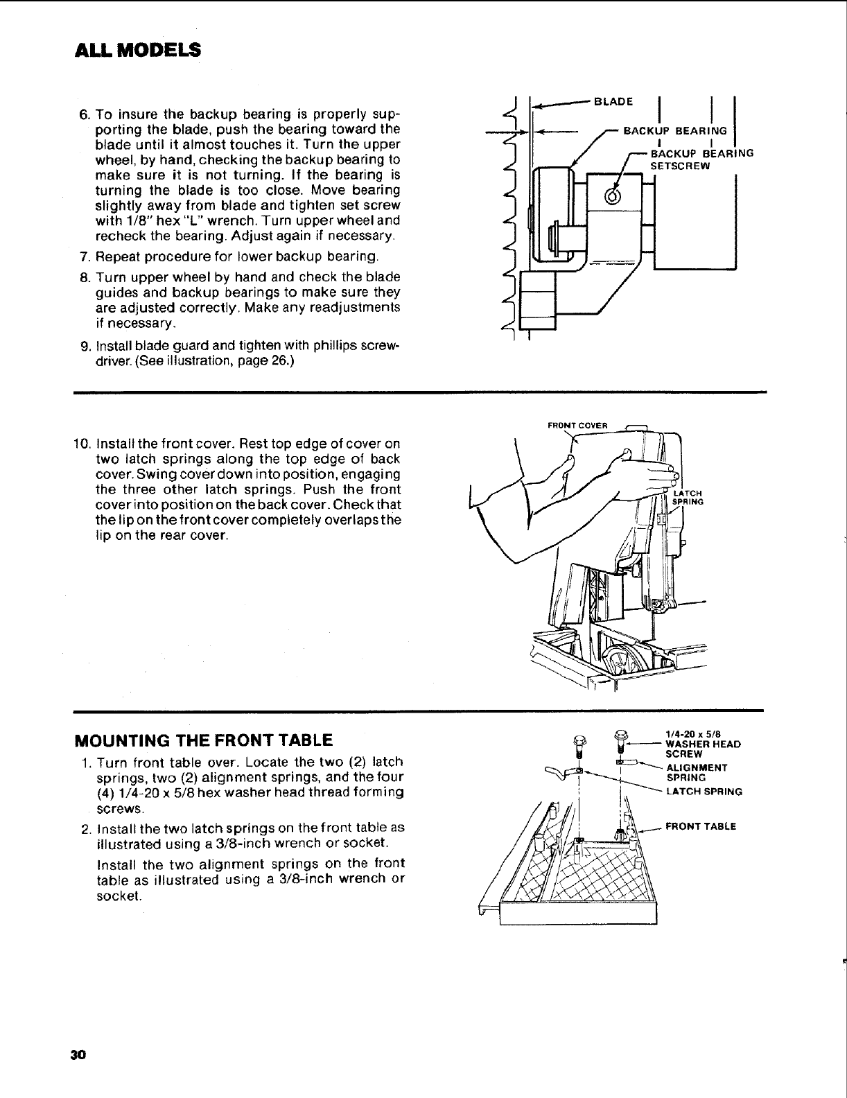
6. To insure the backup bearing is properly sup-
porting the blade, push the bearing toward the
blade until it almost touches it. Turn the upper
wheel, by hand, checking the backup bearing to
make sure it is not turning. If the bearing is
turning the blade is too close. Move bearing
slightly away from blade and tighten set screw
with 1/8" hex "L" wrench. Turn upper wheel and
recheck the bearing. Adjust again if necessary.
7. Repeat procedure for lower backup bearing.
8. Turn upper wheel by hand and check the blade
guides and backup bearings to make sure they
are adjusted correctly. Make any readjustments
if necessary.
9. Install blade guard and tighten with phillips screw-
driver. (See illustration, page 26.)
I----""°° I I
10. Install the front cover. Rest top edge of cover on
two latch springs along the top edge of back
cover. Swing cover down into position, engaging
the three other latch springs. Push the front
cover into position on the back cover. Check that
the lip on the front cover completely overlaps the
lip on the rear cover.
FRONTCOYER
SPRING
MOUNTING THE FRONT TABLE
1. Turn front table over. Locate the two (2) latch
springs, two (2) alignment springs, and the four
(4) 1/4-20 x 5/8 hex washer head thread forming
screws.
2. Install the two latch springs on the front table as
illustrated using a 3/8-inch wrench or socket.
Install the two alignment springs on the front
table as illustrated using a 3!8-inch wrench or
socket.
_1/4-20 x 5/8
_WASHER HEAD
_' _ SCREW
,_ _'-_'"_ ALIGNMENT
,, t ATO.S...NG
_FRONT TABLE
3O
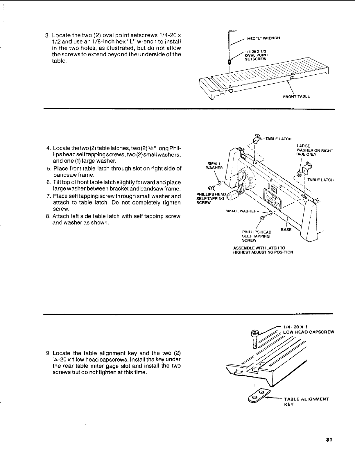
3. Locate the two (2) oval point setscrews 1/4-20 x
1/2 and use an 1/8-inch hex "L" wrench to install
in the two holes, as illustrated, but do not allow
the screws to extend beyond the underside of the
table.
_.//HEX"L"WRENCH
j-1/4-20X1/2
I//OVAL POINT
fSETSCREW
FRONT TABLE
4. Locate thetwo(2)table latches,two(2)3/8 " long Phil-
lips head self tapping screws, two (2)small washers,
and one (1)large washer.
5. Place front table latch through slot on right side of
bandsaw frame.
6. Tilt top of front table latch slightly forward and place
large washer between bracket and bandsaw frame.
7. Place self tapping screw through small washer and
attach to table latch. Do not completely tighten
screw.
8. Attach left side table latch with self tapping screw
and washer as shown.
WASHER
\
PHILLIPS HEAD
SELF TAPPING
SCREW
/_TABLE LATCH
BASE
PHILLIPS HEAD
SELFTAPPING
SCREW
ASSEMBLE WITH LATCH TO
HIGHEST ADJUSTING POSITION
LARGE
WASHER ON RIGHT
SIDE ONLY
ITABLE LATCH
9. Locate the table alignment key and the two (2)
1/4-20x I low head capscrews, Installthe key under
the rear table miter gage slot and install the two
screws but do not tighten at this time.
I- 1/4-20 X 1
_J_ _ HEAD CAPSCREW
TABLE AL:GNMENT
KEY
31
ALL MODELS
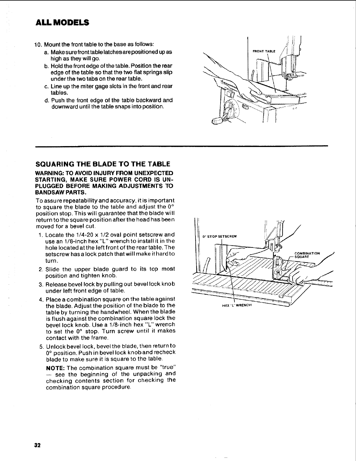
10. Mount the front table to the base as follows:
a. Makesurefronttablelatchesarepositioned upas
high as they will go.
b. Hold the front edge of the table. Position the rear
edge of the table so that the two flat springs slip
under the two tabs on the rear table.
c. Line up the miter gage slots in the front and rear
tables.
d. Push the front edge of the table backward and
downward until the table snaps into position.
FRONT TABLE
SQUARING THE BLADE TO THE TABLE
WARNING: TO AVOID INJURY FROM UNEXPECTED
STARTING, MAKE SURE POWER CORD IS UN-
PLUGGED BEFORE MAKING ADJUSTMENTS TO
BANDSAW PARTS.
To assu re repeatability and accuracy, it is important
to square the blade to the table and adjust the 0°
position stop. This will guarantee that the blade wi II
return to the square position after the head has been
moved for a bevel cut.
1. Locate the 1/4-20 x 1/2 oval point setscrew and
use an 1/8-inch hex "L" wrench to install it in the
hole located at the left front of the rear table. -The
setscrew has a lock patch that will make it hard to
turn.
2. Slide the upper blade guard to its top most
position and tighten knob.
3. Release bevel lock by pulling out bevel lock knob
under left front edge of table.
4. Place a combination square on the table against
the blade. Adjust the position of the blade to the
table by turning the handwheel. When the blade
is flush against the combination square lock the
bevel lock knob. Use a 1/8-inch hex "'L" wrench
to set the 0°stop. Turn screw until it makes
contact with the frame.
5. Unlock bevel lock, bevel the blade, then return to
0°position. Push in bevel lock knob and recheck
blade to make sure it is square to the table.
NOTE: The combination square must be "true"
-- see the beginning of the unpacking and
checking contents section for checking the
combination square procedure.
I _, il
l ir, /
0 ° STOP SETSCREW i_/_ /"
32
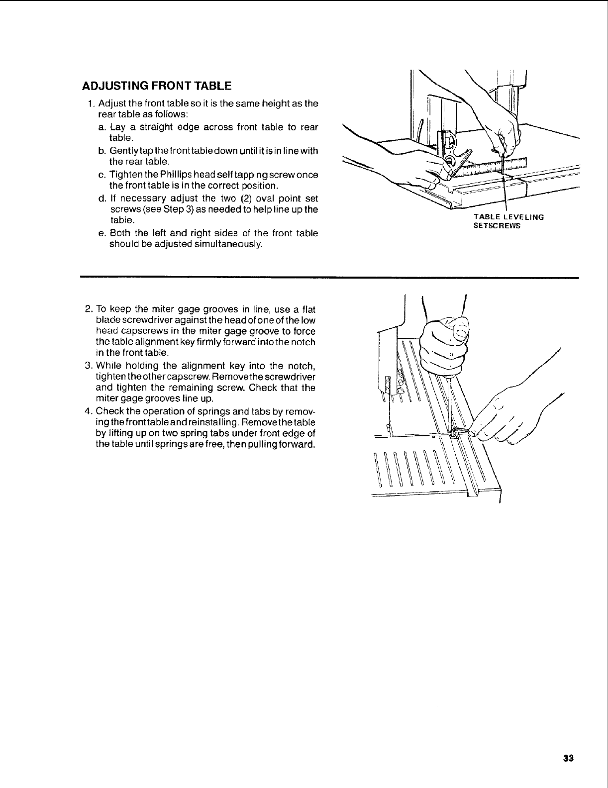
ADJUSTING FRONT TABLE
1. Adjust the front table so it is the same height as the
rear table as follows:
a, Lay a straight edge across front table to rear
table.
b. Gentlytap the fronttable down until it is in line with
the rear table,
c. Tighten the Phillips head self tapping screw once
the front table is in the correct position.
d. If necessary adjust the two (2) oval point set
screws (see Step 3) as needed to help line up the
table.
e. Both the left and right sides of the front table
should be adjusted simultaneously.
TABLE LEVELING
SETSCREWS
2, To keep the miter gage grooves in line, use a flat
blade screwdriver against the head of one of the low
head capscrews in the miter gage groove to force
the table alignment key firmly forward intothe notch
in the front table.
3. While holding the alignment key into the notch,
tighten theother capscrew. Removethe screwdriver
and tighten the remaining screw. Check that the
miter gage grooves line up,
4. Check the operation of springs and tabs by remov-
ing the front table and reinstalling. Removethetable
by lifting up on two spring tabs under front edge of
the table until springs are free, then pulling forward.
33
ALL MODELS
location and function of controls
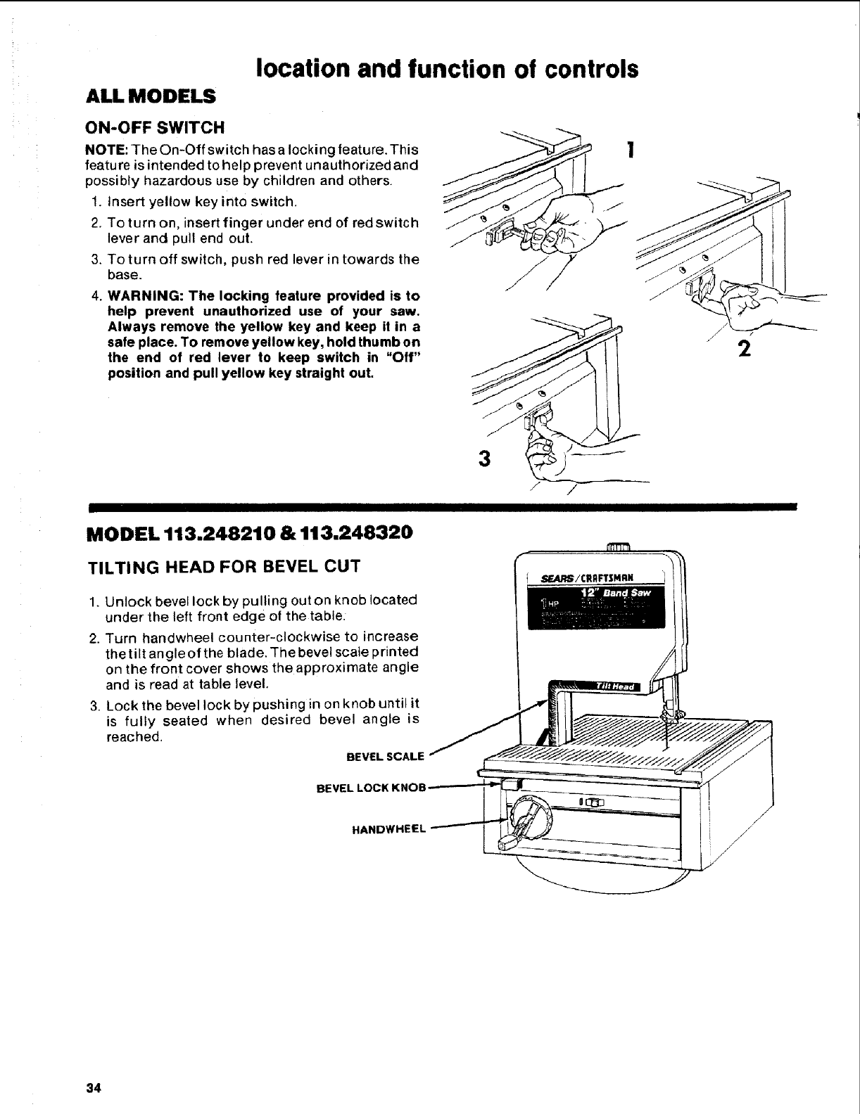
ON-OFF SWITCH
NOTE: The On-Off switch has a locking feature. This
featu re is intended to help prevent unauthorized and
possibly hazardous use by children and others.
1. Insert yellow key into switch.
2. To turn on, insert finger under end of red switch
lever and pull end out.
3. To turn off switch, push red lever in towards the
base.
4WARNING: The locking feature provided is to
help prevent unauthorized use of your saw.
Always remove the yellow key and keep it in a
safe place. To remove yellow key, hold thumb on
the end of red lever to keep switch in "Off"
position and pull yellow key straight out.
3
MODEL 113.248210 & 113,248320
TILTING HEAD FOR BEVEL CUT
/
1. Unlock bevel lock by pulling outon knob located
under the left front edge of the table:
2. Turn handwheel counter-clockwise to increase
the tilt angle of the blade. The bevel scale printed
on the front cover shows the approximate angle
and is read at table level.
3. Lock the bevel lock by pushing in on knob until it
is fully seated when desired bevel angle is
reached.
BEVEL SCALE
BEVEL LOCK KNOB
HANDWHEEL
34
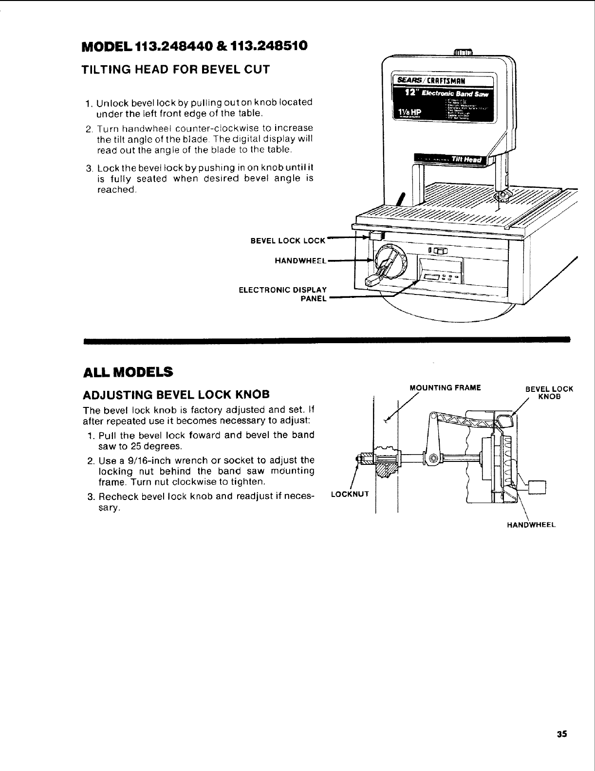
MODEL 113.248440 & 113.248510
TILTING HEAD FOR BEVEL CUT
1, Unlock bevel lock by pulling outon knob located
under the left front edge of the table,
2. Turn handwhee4 counter-clockwise to increase
the tilt angle of the blade. The digital display will
read out the angle of the blade to the table.
3. Lock the bevel lock by pushing in on knob until it
is fully seated when desired bevel angle is
reached.
BEVEL LOCK
HANDWHEf
ELECTRONIC DISPLAY
PANEL
ALL MODELS
ADJUSTING BEVEL LOCK KNOB
The bevel lock knob is factory adjusted and set, If
after repeated use it becomes necessary to adjust:
1. Pull the bevel lock foward and bevel the band
saw to 25 degrees.
2. Use a 9/16-inch wrench or socket to adjust the
locking nut behind the band saw mdunting
frame. Turn nut clockwise to tighten.
3. Recheck bevel lock knob and readjust if neces-
sa ry.
LOCKNUT
MOUNTING FRAME
FBEVEL LOCK
•KNOB
HANDWHEEL
35
basic band saw operation
ALL MODELS
WARNING: FOR YOUR SAFETY, COMPLY WITH
ALL THE SAFETY INSTRUCTIONS ON PAGES 3-5
BEFORE USING THE BAND SAW.
Aband saw is basically a "curve cutting" machine. It
is not capable of doing inside cutting.
Your Craftsman Band Saw is not only capable of the
usual band saw operations, but it can be converted
into a sander as well. You can finish wood, certain
compositions and plastics.
It is also used for straight-line cutting operations
such as crosscutting, ripping, mitering, beveling,
compound cutting, and resawing.
Operation Recommended Blade Size
(Inches)
Cross Cutting 1/4, 3/8, 1/2
Ripping 1/2
Mitering 1/4, 3/8, 1/2
Beveling 1/4, 3/8, 1/2
Compound Cutting 1/4, 3/8, 1/2
Circle Cutting See Chart Below
Resawing 1/2
Curve Cutting 1/8, 1/4
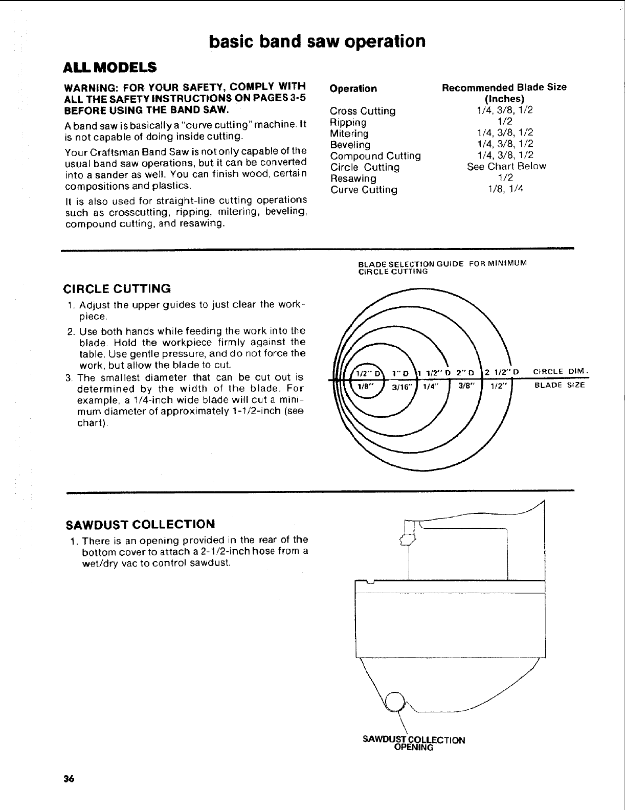
CIRCLE CUTTING
t. Adjust the upper guides to just clear the work-
piece.
2. Use both hands while feeding the work into the
blade. Hold the workpiece firmly against the
table. Use gentle pressure, and do not force the
work, but allow the blade to cut.
3. The smallest diameter that can be cut out is
determined by the width of the blade. For
example, a 1/4-inch wide blade will cut a mini-
mum diameter of approximately 1-1/2-inch (see
chart).
BLADE SELECTION GUIDE FOR MINIMUM
CIRCLE CUTTING
2 112"D CIRCLE DIM.
BLADE SIZE
SAWDUST COLLECTION
1. There is an opening provided in the rear of the
bottom cover to attach a 2-1/2-inch hose from a
wet/dry vac to control sawdust.
SAWDUST COLLECTION
OPENING
36
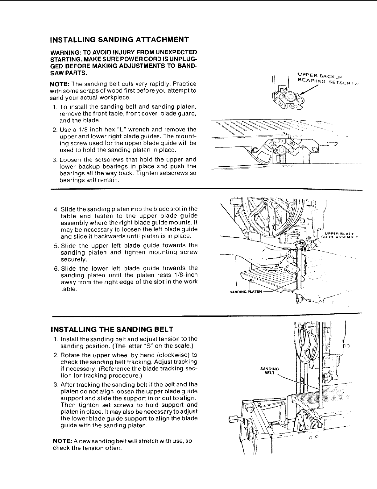
INSTALLING SANDING ATTACHMENT
WARNING: TO AVOID INJURY FROM UNEXPECTED
STARTING, MAKE SURE POWER CORD IS UNPLUG-
GED BEFORE MAKING ADJUSTMENTS TO BAND-
SAW PARTS.
NOTE: The sanding bett cuts very rapidly. Practice
with some scraps of wood first before you attempt to
sand your actual workpiece.
1. To install the sanding belt and sanding platen,
remove the front table, front cover, blade guard,
and the blade.
2. Use a 1/8-inch hex "L" wrench and remove the
upper and lower right blade guides. The mount-
ing screw used for the upper blade guide will be
used to hold the sanding platen in place.
3. Loosen the setscrews that hold the upper and
lower backup bearings in place and push the
bearings all the way back_ Tighten setscrews so
bearings will remain.
4. Slide the sanding platen into the blade slot in the
table and fasten to the upper blade guide
assembly where the right blade guide mounts. It
may be necessary to loosen the left blade guide
and slide it backwards until platen is in place.
5, Slide the upper left blade guide towards the
sanding platen and tighten mounting screw
securely.
6. Slide the lower teft blade guide towards the
sanding platen until the platen rests 1/8-inch
away from the right edge of the slot in the work
table, SANDING PLATEN
INSTALLING THE SANDING BELT
1. Install the sanding belt and adjust tension to the
sanding position. (The letter "S" on the scale.)
2. Rotate the upper wheel by hand (clockwise) to
check the sanding belt tracking. Adjust tracking
if necessary. (Reference the blade tracking sec-
tion for tracking procedure.)
3. After tracking the sanding belt if the belt and the
platen do not align loosen the upper blade guide
support and slide the support in or out to align.
Then tighten set screws to hold support and
platen in place, it may also be necessary to adjust
the lower blade guide support to align the blade
guide with the sanding platen.
NOTE: A new sanding belt will stretch with use, so
check the tension often.
SANDING
BELT
,Ii I
'%
. i_ii
!1-'2
Sears recommends the following Accessories
Caster Set for Leg Set ........... 9-22222, 9-22221
Miter Gauge ............................ 9-29929
Hold-Down Clamp for Miter Gauge ....... 9-29928
Stop-Rods for Miter Gauge .............. 9-29924
Rip Fence .............................. 9-23402
Blades and Sanding Belts ............ See Catalog
Circle Cutting Attachment ............... 9-23411
Power Tool Know How Handbooks
Radial Saw (includes band saw section)., 9-2917
Table Saw (includes band saw section)... 9-2918
Sears may recommend other accessories net listed in
the manual. See your nearest Sears store or Catalog
department for other accessories.
Do not use any accessory unless you have received and
read complete instructions for its use.
ALL MODELS
maintenance
WARNING: FOR YOUR OWN SAFETY, TURN
SWITCH "OFF" AND REMOVE PLUG FROM POWER
SOURCE OUTLET BEFORE MAINTAINING OR
LUBRICATING YOUR BAND SAW.
Tires
Pitch and sawdust that build up on the tires should
be removed with a stiff brush or scraped off with a
piece of wood.
CAUTION: To avoid damaging the tires do not use a
sharp knife or any kind of solvent.
When the tires become worn they should be replaced.
When replacing the tires, stretch them around the
wheels but do not glue them on.
ADJUSTING BAND SAW BEVEL TRAVEL
If the band saw will not hold its position when at a
bevel angle, and before the bevel look is locked, or if
it is difficult to change the bevel angle, an adjustment
is necessary to correct the force required to bevel
the band saw.
To adjust the force required to bevel the band saw,
locate the three (3) capscrews holding the frame to
the motor mount. The capscrews are located in the
recessed area behind the hub of the lower wheel at
the 2 o'clock, 6 o'clock, and 10 o'clock positions. Use
a 3/16-inch hexagonal "L" wrench that has a 4-inch
leg, reach between the spokes of the lower wheel to
the capscrews. Adjust the capscrews equally until
the bevel action is smooth and the saw wilt hold its
position before the bevel lock is locked.
ADJUSTING THE UPPER BLADE GUIDE
TRAVEL
If the upper guide bar will not move up and down
easily or falls when the lock knob is loosened, the
following adjustment should be performed.
1. Remove the Guide Bar Lock Knob and the
washer which is under it.
2. Using a 7/16" socket or wrench, tighten the nut
which is under the washer to just tight.
3. Then loosen the same nut 1 turn.
4. Move the guide bar up and down to check for
smooth movement while still holding its position
when released.
5. Make further adjustments to the nut as required
to get the guide bar to move smoothly and hold
its position when released.
6. Reinstafl the washer and Guide Bar Lock Knob.
General Maintenance
Keep your band saw clean. Remove the sawdust
from the inside. Vacuum or blow out frequently.
Do not allow filth to build up on the table, the guides
orthe back-up bearings. Clean them with Craftsman
Gum and Pitch Remover.
CAUTION: Do not immerse the backup bearings in
the gum and pitch remover.
Put a thin coat of paste wax on the table so that the
wood slides easily while cutting.
38
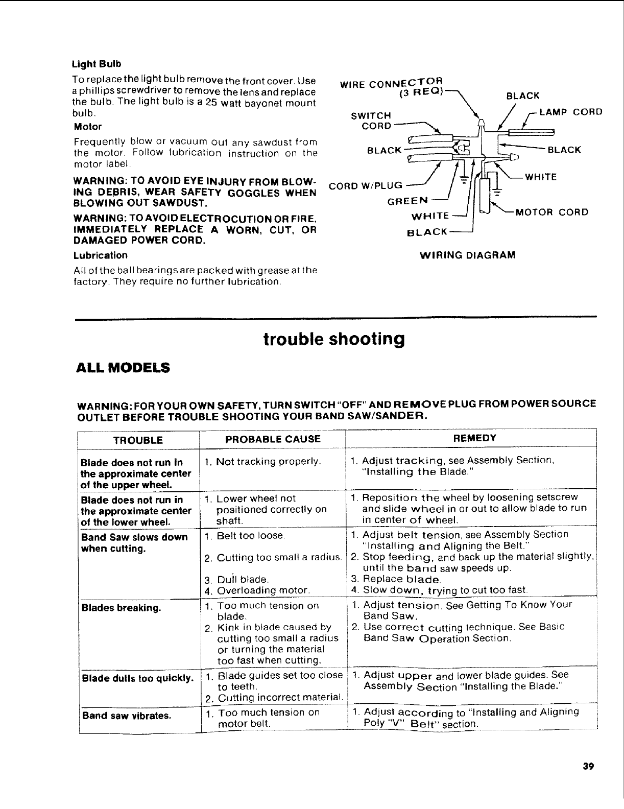
Light Bulb
To replace the light bulb remove the front cover. Use
a phillips screwdriver to remove the lens and replace
the bulb. The light bulb is a 25 watt bayonet mount
bulb.
Motor
Frequently blow or vacuum out any sawdust from
the motor, Follow lubrication instruction on the
motor label.
WARNING: TO AVOID EYE INJURY FROM BLOW-
ING DEBRIS, WEAR SAFETY GOGGLES WHEN
BLOWING OUT SAWDUST.
WARNING: TO AVOID ELECTROCUTION OR FIRE,
IMMEDIATELY REPLACE AWORN, CUT, OR
DAMAGED POWER CORD.
Lubrication
All of the ball bearings are packed with grease at the
factory. They require no further lubrication.
WIRE CONNECTOR
(3 REO)---_ BLACK
SWITCH "_k /F-LAMP CORD
/ / _r_JJ.1] "_----WHITE
CORD W!PLUG_ /"II€
GRE_NHI--_E__ L_MOTOR CORD
BLACK_
WIRING DIAGRAM
ALL MODELS
trouble shooting
WARNING: FOR YOUR OWN SAFETY, TURN SWITCH "OFF" AND REMOVE PLUG FROM POWER SOURCE
OUTLET BEFORE TROUBLE SHOOTING YOUR BAND SAW/SANDER.
TROUBLE PROBABLE CAUSE REMEDY
1. Not tracking properly. 1. Adjust tracking, see Assembly Section,
I "Installing the Blade."
1.
Blade does not run in
the approximate center
of the upper wheel.
Blade does not run in
the approximate center
of the lower wheel.
Band Saw slows down
when cutting.
Blades breaking.
I
Blade dulls too quickly.
Band saw vibrates.
1,
2.
3.
4.
1.
2.
2.
Lower wheel not 1,
positioned correctly on
shaft.
Belt too loose. 1,
Cutting too small a radius 2.
Duil blade. 3.
Overloading motor, i 4.
Too much tension on 1.
blade.
Kink in blade caused by 2.
cutting too small a radius
or turning the material
too fast when cutting.
Blade guides set too close 1.
to teeth.
Cutting incorrect material.
Too much tension on -11
motor belt.
Reposition the wheel by loosening setscrew
and slide wheel in or out to allow blade to run
in center of wheel.
Adjust belt tension, see Assembly Section
"Installing and Aligning the Belt."
Stop feeding, and back up the material slightly,
until the band saw speeds up.
Replace blade.
Slow down, trying to cut too fast.
Adjust tension. See Getting To Know Your
Band Saw,
Use correct cutting technique. See Basic
Band Saw Operation Section.
Adjust upper and lower blade guides. See
Assembly Section "Installing the Blade."
Adjust according to "Installing and Aligning {r
Poly "V" E_e_t" section.
39

trouble shooting--motor
ALL MODELS
NOTE: Motors used on wood-working tools are particularly susceptible to the
accumulation of sawdust and wood chips and should be blown out or "vacuumed"
frequently to prevent interference with normal motor ventilation and proper
operation of the centrifugally-operated starting switch.
TROUBLE PROBABLE CAUSE REMEDY
Excessive noise. 1. Motor. 1. Have motor checked by qualified service
technician. Repair service is available at your
nearest Sears store.
1.
Motor tails to develop
full power. NOTE:
LOW VOLTAGE: (Power
output of motor
decreases rapidly with
decrease in voltage at
motor terminals, For
example, a reduction of
10% in voltage causes
areduction of 19% in
maximum power output
of which the motor is
capable, and a reduction
of 20% in voltage causes
a reduction of 36% in
maximum power
output.)
Motor starts slowly
or fails to come up
to full speed.
Motor overheats.
Starting switch in
motor will not operate.
Motor stalls
(resulting in blown
fuses or tripped
circuit breakers).
Frequent opening of
fuses or circuit
breakers.
Circuit overloaded with
lights, appliances and
other motors.
Undersize wires or circuit
too long.
General overloading of
power company
facilities.
1. Low voltage.
2. Windings burned out
or open.
3. Starting switch not
operating.
1. Motor overloaded.
2. Improper cooling (Air
circulation restricted
through motor due to
sawdust accumulation_
1. Burned switch contacts
(due to extended hold-in
periods caused by low line
voltage_ etc.)
2. Shorted capacitor.
3. Loose or broken
connections.
1. Starting switch not
operating.
2. Voltage too low to permit
motor to reach operating
speed.
3. Fuses or circuit breakers
do not have sufficient
capacity.
1. Motor overloaded.
2. Fuses or circuit breakers
do not have sufficient
capacity.
3. Starting switch not
operating (motor does not
reach speed).
1. Do not use other appliances or motors on
same circuit when using the saw.
2. Increase wire sizes, or reduce length of wiring.
See "Motor Specifications and Electrical
Requirements" section.
3. Request a voltage check from the power
company.
1. Request voltage check from the power
company_ Check size of circuit wiring.
2. Have motor repaired or replaced.
3. Blow out sawdust from motor. Have motor
repaired.
1. Feed work slower into blade.
2. Clean out sawdust to provide normal air
circulation through motor. See "Maintenance
and Lubrication" section.
1. Have switch replaced and request a voltage
check from the power company.
2. Have capacitor tested and replace if defective.
3. Have wiring checked and repaired.
1. Have switch replaced.
2. Request voltage check from the power
company.
3. Install proper size fuses or circuit breakers.
1.
2. Feed work slower into blade_ .........
Install proper size fuses or circuit breakers.
Check: that wiring will handle load.
3. Have switch replaced. Blow out sawdust.
40

trouble shooting -- electronics
MODEL 113.248440 & 113.248510
PROBLEM
I
No display when
is pressed.
Display shows
I1
PROBABLE CAUSE
1. Battery incorrectly
installed or missing.
2. Battery contacts dirty
or corroded.
3. Battery dead.
4. Digital display failure.
1. Normal display when
battery is first installed in
unit.
2. Bevel display was not
ref-set.
3. Poor battery contact to
indicator display leads
causing intermittent
power to display.
4. Digital display failure.
SUGGESTED CORRECTIVE ACTION
.......... _ ...... -- ..... __ ...... --H
- Adjust battery position in compartment.
- Install battery.
- Clean battery contacts.
-Replace battery Battery is 6 volt, size J, !
alkaline type. ,
- Have electronics checked by qualified
technician. Repair service available at nearest
Sears Store. --
- No action required.
- Follow procedure for setting bevel reference
point in this manual.
- Clean battery contacts. Adjust battery position
in compartment.
- Have electronics checked by qualified service
technician. Repair service available at nearest
Sears store.
Display dim. 1. Low battery voltage. - Replace battery. Battery is 6 volt, size J.
alkaline type.
2. Temperature below 32° F. - Allow saw to warm above 32° F.
Display dark. 1. Temperature above 120°F. - Allow saw to cool below 120° F.
Display blanks after 1. Normal. - Press IO"_OF_]key. Display should return.
a few minutes.
Display shows 1. - Reset bevel zero reference.
FFc,:EEl
Display will reset to
zero but immediately
shows when bevel is
moved,
IEEEEI
Head tilted too rapidly
for digital display to
monitor.
1. Encoder or digital
display defective.
1. Wrong display function
selected.
2. Encoder or digital
display defective.
3. Rib on lower slide
not engaging encoder.
i _ Have electronics checked by qualified
itechnician, Repair service available at nearest
Sears store.
- Select bevel function.
- Have electronics checked by qualified
technician. Repair service available at nearest
Sears store.
- Have electronics checked by qualified
technician. Repair service available at nearest
Sears store.
Display does not
change when bevel
is moved.
41

trouble shooting --- electronics
MODEL 113.248440 & 113.2485t 0
PROBLEM
Display does not
change when blade
speed is changed.
Display changes back
and forth between
3000 & 2800 in fpm
function.
Display does not
change when blade
tension is changed.
PROBABLE CAUSE
1. Wrong display
function selected.
2. Encoder or digital
display defective.
1. Slight variations in
in blade speed.
1. Wrong display function
selected.
2. Encoder or digital
display defective.
3. Encoder not engaged
with tab on actuator.
Display shows 1
in tension function.
! E 1
Blade too tight.
SUGGESTED CORRECTIVE ACTION
- Select FPM function.
-Have electronics checked by qualified
technician. Repair service available at nearest
Sears store.
- Normal.
- Select _ function.
- Have electronics checked by qualified
technician. Repair service available at nearest
Sears store.
- Engage tab of actuator with encoder.
- Normal. Reduce blade tension.
42
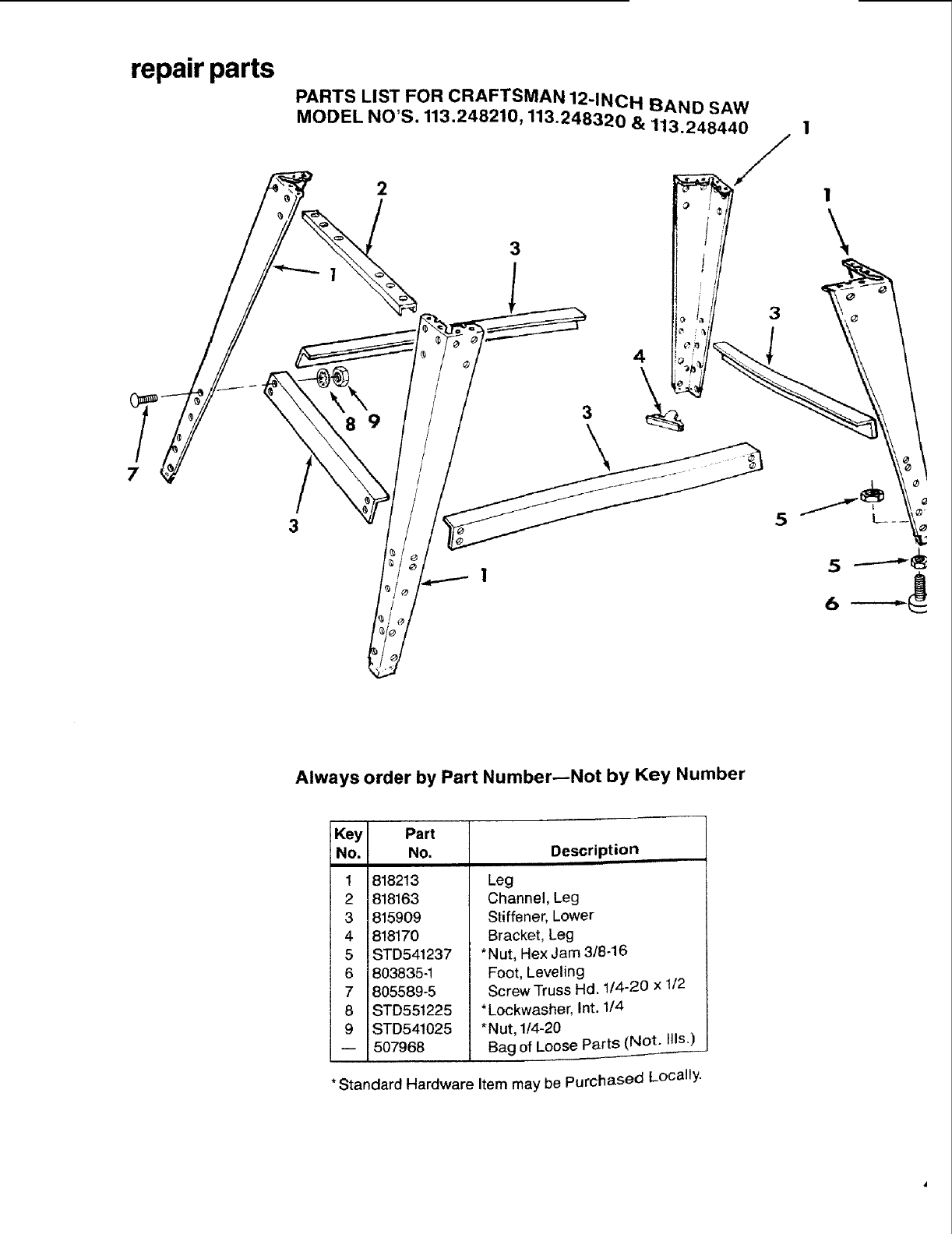
repair parts
PARTS LIST FOR CRAFTSMAN 12-INCH BAND SAW
MODEL NO'S. 113.248210, 113.248320 & 113.248440
7
89
3
3
\
4
\
3
Always order by Part Number--Not by Key Number
Key
No.
1
2
3
4
5
6
7
8
9
Part
No.
818213
818163
815909
818170
STD541237
803835-1
805589-5
STD551225
STD541025
507968
Description
Leg
Channel, Leg
Stiffener, Lower
Bracket, Leg
*Nut, Hex Jam 3J8-16
Foot, Leveling
Screw Truss Hd. 1/4-20 x 112
*Lockwasher, Int. 1/4
*Nut, 1/4-20
Bag of Loose Parts (Not. _lls.)
*Standard Hardware Item may be Purchased Locally.
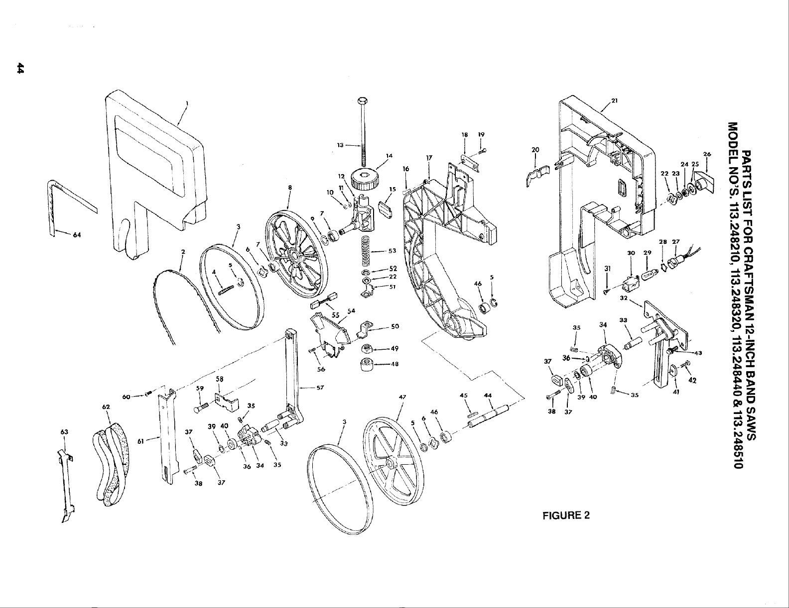
63
64
2
3
36 34
38 37
47
t7
\
\\
46
18 19
\
45 44 _,_
35
/
37
38 3;'
33
34
FIGURE 2

PARTS LIST FOR CRAFTSMAN 12-INCH BAND SAW
MODEL NO'S. 113.248210, 113.248320, 113.248440 & 113.248510
Always order by Part Number--Not by Key Number
FIGURE 2--DRIVE ASSEMBLY PARTS
Key Part
No, No.
1 507830
2 9-26595
3 41815
4 816600
5 STD582062
6 41711
7 805034
8 816419-2
9 38879
10 STD541431
11 STD551031
12 816364
13 816446
14 816437
15 816350
16 808380-5
17 816433
18 816453
19 STD533110
Description
Cover, Front w/Label
1-Blade, Band Saw
Tire
Screw, SI. Hd. Set
5/16-18 x 2-1/8
*Ring, Retaining 5/8
Washer, Spring
Bearing, Ball
Wheel, Upper
Ring, Retaining 1-3/8
* Nut, Lock 5/16-18
*Washer, 21/64 x 5/8 x !132
Support Assembly,
20 816464
21 816429
22 808447-2
23 60128
24 STD541425
25 i805552-20
26 816435
27 816444
28 808335-2
29 STD372252
30 816380
31 808380-1
Upper Wheel
Screw, Blade Tension
3/8-16 x 10-1/4
Knob, Blade Tension
Plate, Support
Screw, Pan Hd.
Plastite #8 x 3/4
Frame
Plate, Pivot Support
* Bolt, Carriage High Strength
5/16-18 x 1
Latch, Cover
Cover, Rear
Washer, Wave 3/8 x 3/4 x .016
Washer, 17/64 x 5/8 x 1/32
* Nut, Lock 1/4
Washer 17/64 x 1x 1116
Knob, 1/4-20
Socket, Light
Retainer
*Bulb, Light
Lens
Screw, Pan Hd.
Plastite #6 x 3t8
Key Part
No. No.
32 816362
33 816356
34 816365
35 STD502502
36 808819-1
37 816379
38 60334
39 60416
40 STD315485
41 818000
42 816273
43 815865-2
44 816387
45 STD580103
46 STD315238
47 69059
48 816349
49 816358
50 816599
51 816377
52 STD551037
53 816353
54 816406
55 816393
56 STD510807
57 816363
58 816361
59 109093
60 813786-2
61 816388
62 9-22361
63 816368
64 816606
5O8014
-- SP5292
Description
Slide Assembly, Lower
Shaft, Bearing Support
Support, Guide
*Screw Soc. Set 1/4-20 x 1/4
Ring, Retaining
Guide, Blade
Screw, Socket Button
Cap No. 10-32 x 3/4
-kRing, Retaining 5/16
*Bearing, Ball
Guide, Lower slide
Screw, Truss Hd. 1/4-20 x 1/2
Screw, Hex Wash Hal.
1/4-20 x 5/8
Shaft, Lower Wheel
*Key, 3/16 Sq. x 15116
*Bearing, Ball
Wheel, Drive
Follower
Nut, Heavy Square 3/8-16
AActuator, Tension
Indicator, Tension
*Washer, .380 x .750 x .03
Spring, Blade Tension
AEncoder, Spd./Ten.
,,Cord, Sensor
*Screw, Pan Hd. Ty "T"
8-32 x 3/4
Slide Assembly, Upper
Lock, Slide
Bolt, Carriage 1/4-20 x 1-3/4
Screw, Pan Cross Hd.
Type "TT" No. 8-32 x 5/8
Guard, Blade
1"Belt, Sanding 1/2 x 80
Platen, Sanding
==Scale, Bevel
Bag of Loose Parts (Not Ills.)
Owners Manual (Not Ills.)
*Standard Hardware Item may be Purchased Locally.
1-Stock Item--May be secured through the Hardware Department
of most Sears Retail Stores or Catalog Order Houses.
If this part is removed, discard and replace with a new push nut.
AMode1113.248440 and 113.248510.
==Model 113.248210 and 113.248320.
45
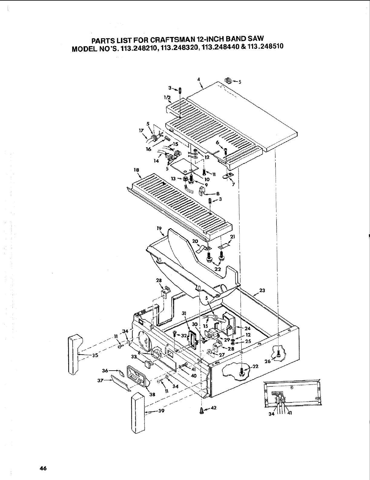
PARTS LIST FOR CRAFTSMAN 12-INCH BAND SAW
MODEL NO'S. 113.248210,113.248320, 113.248440 & 113.248510
5
17
16
14
18 5
f9
28
\23
46

PARTS LIST FOR CRAFTSMAN 12-INCH BAND SAW
MODEL NO'S. 113.248210, 113.248320, 113.248440 & 113.248510
Always order by Part Number--Not by Key Number
FIGURE 3mBASE COMPONENTS
Key Part
iNo. No.
1 816421
2
3
5
6
7
8
9
816420
806036-2
816423
815868
810214-2
816371
62204
STD522505
10 816372
11 816333-2
12 STD551210
13 169123-12
14 816448
15 816436
16 STD375006
17 816888
18 816434
t9 816417
20 818529
21 816370
22 815865-2
23 818390
Description
Table, Rear
(Model 113.248210 only)
mOATable, Rear
Screw, Locking Set
1/4-20 x 1/2
Cover Base
(Model 113.248210 only)
Relief, Strain
Screw, Low Hd. Cap
1/4-20 x 5/8
Key,Table Alignment
Clip, Cord
*Screw, Hex Wash Hd.
1/4-20 x 1/2
Plate, Cover
Screw, Pan Hd. Type "TT"
10-32 x 3/8
* Lockwasher, Int. #10
Relief, Strain
Cord, w/Plug
Cord, Switch
*Connector, Wire
Cord, Motor
Table, Front
Cover, Bottom
Spring, Table Latch
Spring, Table Alignment
Screw, Hex Washer Hd.
Type "TT" 1/4-20 x 518
Base Asserpbly Model
(113.248210 & 113.248320)
Key IPart
No. No.
23 818391
24 816403
25 STD541110
26 STD611005
27 STD551012
28 818777
29 816113
30 808380-2
31 818569
32 STD51!105
33 9-22256
34 STD551010
35 818193
36 STD363569
37 816376
38 816404
39 818192
4O STD551206
41 808380-1
42 60419
507741
Description
B_,Base Assembly
Box, Switch
*Nut, Hex 10-32
*Screw, Pan Hd. TyAB
10 x1/2
(Model 113.248210 only)
*Washer, Large 7/32 x 1x
1/16
Latch, Table
Switch, Locking
Screw, Pan Hd. Plastite
#8 x 3/8
Gasket
*Screw, Pan Cross
10-32 x 1/2
1-Key,Switch
*Washer, Small 13/64 x 5/8 x
1t32
Cap, Trim, L.H.
IA-A-Battery
i_,Lid Battery
IAControl, Band Saw
Cap, Trim R.H.
IA * Lockwasher, Internal #6
iAScrew, Pan Hd. Plastite
#6 x 3t8
Screw, Pan Hd. Plastite
#8 x t/2
Bag of Loose Parts
(Not Ills.)
I
*Standard Hardware Item may be Purchased Locally.
AMode1113.248440 Only
OMode1113.248320 Only
==Model113.248510 Only
_Can also use these battery numbers:
Eveready #539
Rayovac #867
Duracel #7K67
1-Stock Item--May be secured through the
Hardware Department of Most Sears Retail Stores
or Catalog Order Houses.
47
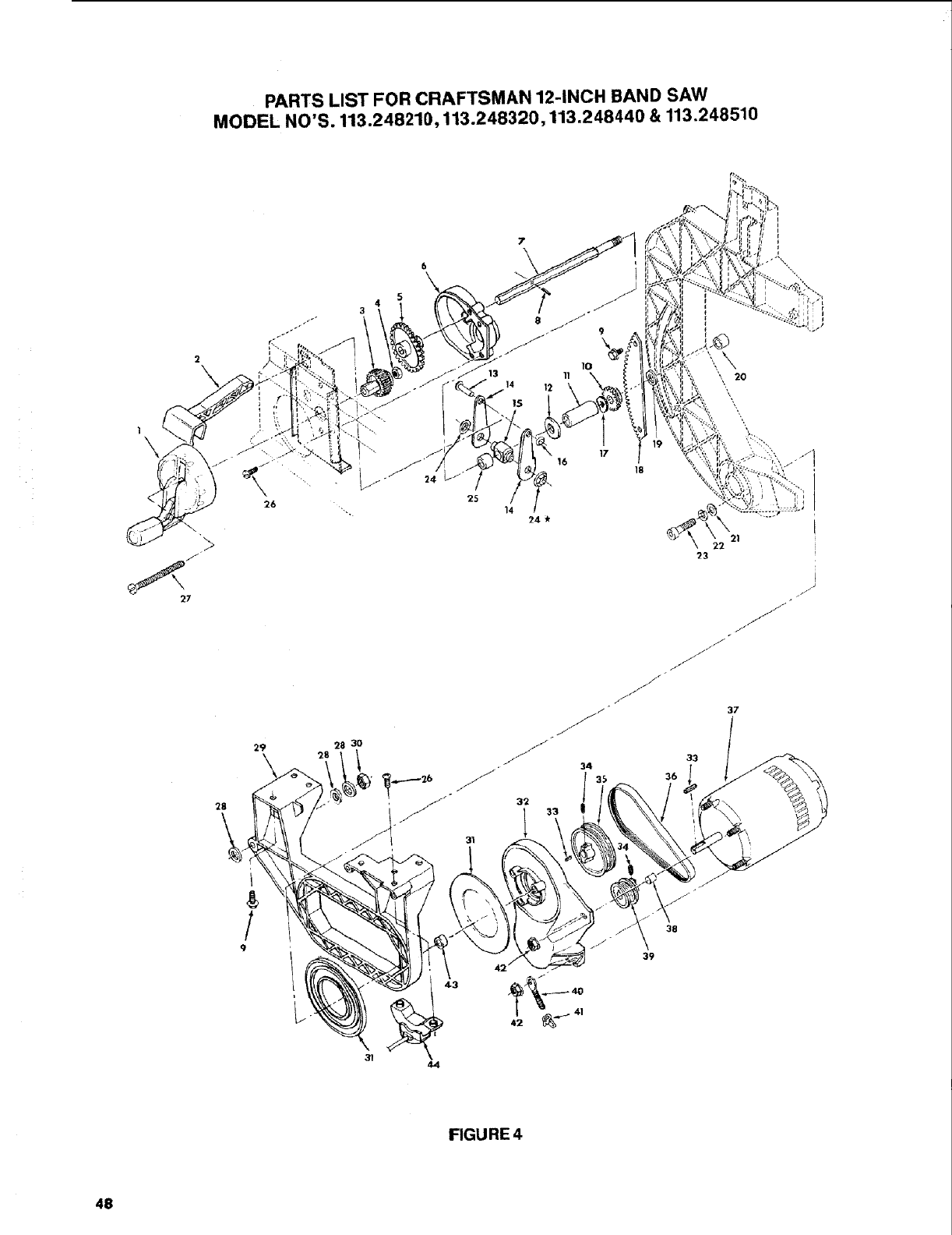
PARTS LIST FOR CRAFTSMAN 12-INCH BAND SAW
MODEL NO'S. 113.248210,113.248320,113.248440 & 113.248510
29
28
/
9
4
3
28 30
F
4,4
7
\ I
17
16 18
14 24
22
23
\
J
J
_J
33
36
FIGURE 4
48

PARTS LIST FOR CRAFTSMAN 12-INCH BAND SAW
MODEL NO'S. 113.248210, 113.248320, 113.248440 & 113.248510
Always order by Part Number--Not by Key Number
FIGURE 4--BEVEL DRIVE AND MOTOR MOUNT ASSEMBLY PARTS
Key Part
No. No,
1 816499
2 816386
3 816381
4 STD541110
5 8t6384
6 816543
7 816382
8 STD571207
9 815865-2
10 816348
11 802392-38
12 STD551050
13 815774-3
14 816360
15 816359
16 60208
17 813024-4
18 816443
19 60317
20 816452
21 STD551012
22 STD551125
23 815992-1
Description
Handwheel Assembly
Knob, Bevel Lock
Pinion, Handwheel
* Nut, Hex 10-32
Gear, Handwheel
Cover, Bevel Gear
Shaft, Bevel
*Pin, Roll 1/8 x 3/4
Screw, Hex Washer Hd.
Ty TT 1/4-20 x 5/8
Pinion, Bevel Drive
Spacer 1/2 x 2
*Washer, .507 x 1.25 x .125
Rivet, 1/4 x 1-1/8
Cam, Bevel Lock
Mount, Bevel Lock
-k Nut, Push 1/4
Washer, Spring
Gear, Segment
Washer, 21132x 1x 1/64
Spacer, 9/16 x 1/4
*Washer, 17/64 x 1/2 x 1/32
* Lockwasher, 1/4
Screw, Hex Socket Head
Ty "TT" 1/4-20 x 3t4
Key Part
No. No.
24 60240
25 816465
26 60419
27 809372-18
28 STD551037
29 816504
30 9414202
31 817165
32 816422
33 STD580103
34 STD503105
35 816407
35 818775
36 816439-2
37 816612
38 60453
39 816390
39 818776
40 816815
41 STD541631
42 816817
43 816445
44 816405
Description
_Nut, Push 3/8
Spacer, 1/2 x .59
Screw, Pan Hd.
Plastite #8 x 1/2
Screw, Pan Hd. 10-32 x 2
*Washer, .380 x .750 x .03
Support Frame
Nut, Lock 3/8-16
Washer, Plastic
Mount, Motor
*Key 3t16 Sq. x 15/16
*Screw, Set 5/16 -18 x 1t2
IIoAPulley, Polyrib 2 Step
Pulley, Polyrib 3.5 In.
Belt, Poly V
®Motor, 1725 R.P.M.
Spacer, Motor Mount
#10 x 5/16
imAPulley, Polyrib 2 Step
Pulley Polyrib 1.75 In.
Stud, Belt Tension
*Nut, Die Cast Wing 5/16 x 18
Nut, Hex Flange Lock 10-32
Bushing, Rubber
IlAEncoder Bevel
*Standard Hardware Item may be Purchased Locally.
_lf this part is removed, discard and replace with new push nut.
_,_,Anyattempt to repair this motor may create a hazard unless repair is done by a Qualified Service Technician.
Repair Service is available at your nearest Sears Store.
,&Model 113.248440 Only
OMode1113.248320 Only
==Model 113.248510 Only
49
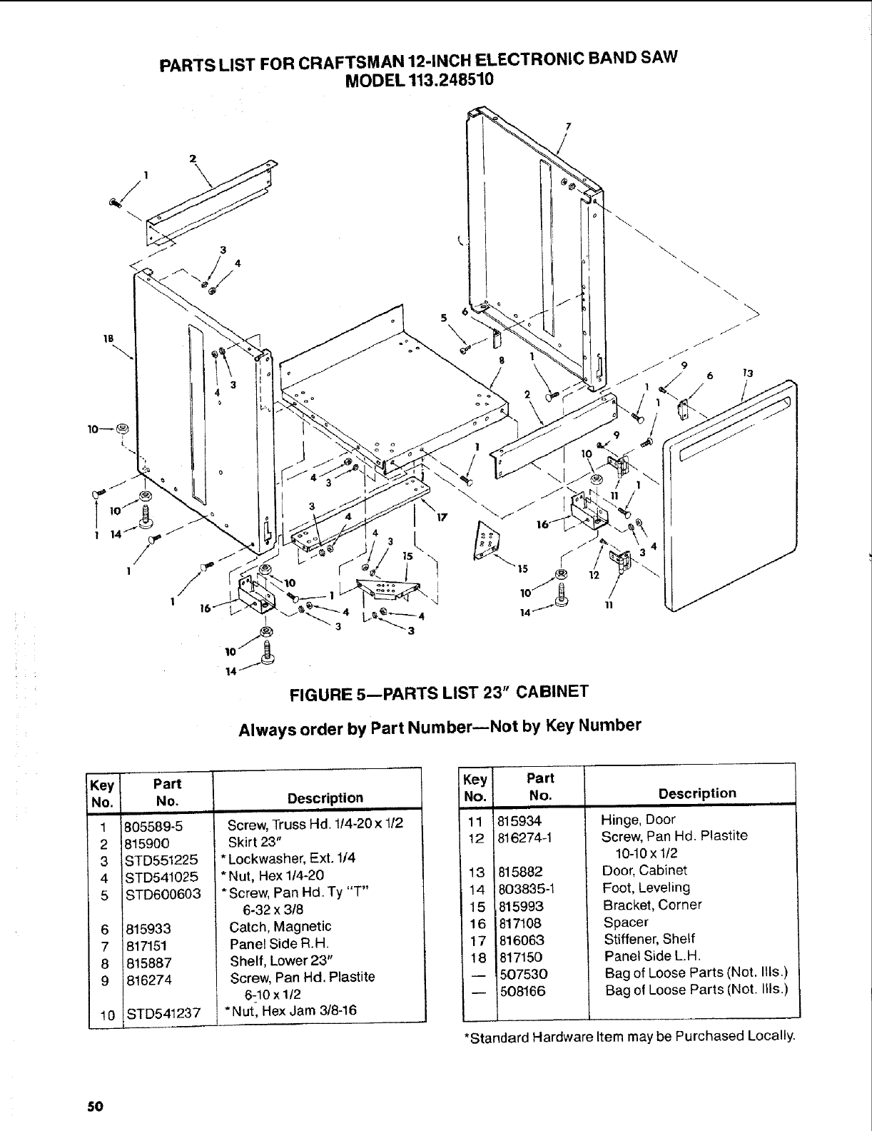
PARTS LIST FOR CRAFTSMAN 12-INCH ELECTRONIC BAND SAW
MODEL 113.248510
10
FIGURE 5--PARTS LIST 23" CABINET
Always order by Part Number--Not by Key Number
13
Key Part
No. No.
1 805589-5
2 815900
3 STD551225
4ISTD541025
5 STD600603
6
7
8
9
10
81593 3
817151
815887
816274
STD541237
Description
Screw, Truss Hd. 1/4-20 x1/2
Skirt 23"
* Lockwasher, Ext. 1/4
*Nut, Hex 1/4-20
* Screw, Pan Hd. Ty "T"
6-32 x 3/8
Catch, Magnetic
Panel Side R.H.
Shelf, Lower 23"
Screw, Pan Hd. Plastite
6-10 x 1/2
* Nut, Hex Jam 3/8-16
Key Part
No. No.
II
11 815934
12 816274-1
13
14
15
16
17
18
815882
803835-1
815993
817108
816063
817150
507530
508166
Description
Hinge, Door
Screw, Pan Hd. Plastite
10-10x 1/2
Door, Cabinet
Foot, Leveling
Bracket, Corner
Spacer
Stiffener, Shelf
Panel Side L.H.
Bag of Loose Parts (Not. Ills.)
Bag of Loose Parts (Not. Ills.)
*Standard Hardware Item may be Purchased Locally.
50

NOTES
51
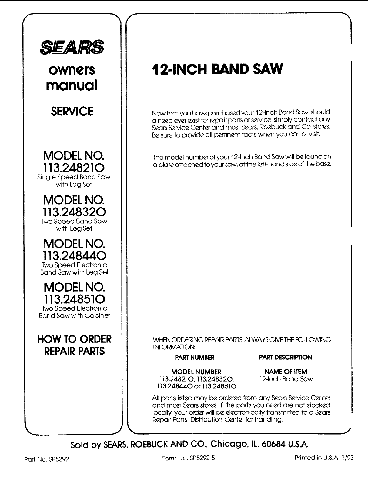
f _,, f
_AIRS
owners
manual
SERVICE
MODEL NO.
113.248210
Single Speed Band Saw
with Leg Set
MODEL NO.
113.248320
Two Speed Band Saw
with Leg Set
MODEL NO.
113.248440
Two Speed Electronic
Band Saw with Leg Set
MODEL NO.
113.248510
Two Speed Electronic
Band Saw with Cabinet
HOW TO ORDER
REPAIRPARTS
12-INCH BAND SAW
Nowthat you have purchased your 'I2-Inch Band Saw, should
a need _*verexist for repair parts or service, simply contact any
Sears Service Center and most Sears, Roebuck and Co. stores,
Be sure to provide all pertinent facts when you calJ or visit.
The model number of your fl2-1nch Band Sawwill b_ found on
a plate attached to your saw, at the I_fft-hand side of the base.
WHEN ORDERING REPAIR PARTS,ALWAYS GIVE THEFOLLOWING
INFORMATION:
PART NUMBER PARTDESCRIPTION
MODEL NUMBER NAME OF ITEM
113.248210, 113.248320, fl2-1nch Band Saw
113.248440 or 113.248510
All parts listed may b_ ordered from any S_ars S_rvice Center
and most S_ars stor_s. If the parts you need are not stocked
locally, your order will be el_ctronically transmitted to a Sears
Repair Parts Di.-_rribution C__nter for handling.
Sold by SEARS,ROEBUCK AND CO., Chicago, IL. 60684 U.SA
J
Part No. SP5292 Form No. SP5292-5 Printed in U.S.A. 1/93
